Network synchronization
This guide describes network synchronization capabilities available with SR Linux. These capabilities include physical layer frequency distribution via Synchronous Ethernet and packet based distribution of frequency and time using the precision time protocol (PTP) of IEEE 1588.
In SR Linux R23.3, network synchronization is supported on the following platform only:
- 7220 IXR-D5, model 3HE17735AB (w/Timing)
- a reference frequency for mobile base stations to tune their carrier frequencies
- an accurate frequency for the delivery of time using PTP
The network time architecture in the following figure shows how network synchronization is commonly distributed in a hierarchical PTP topology at the physical layer.
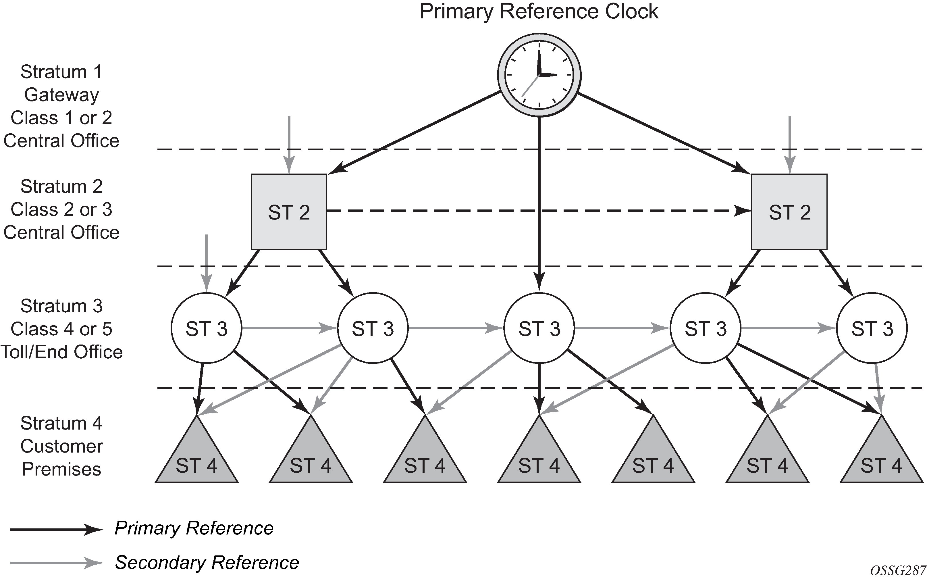
This architecture provides the following benefits:
-
limits the need for high-quality clocks at each network element
-
only requires reliable and accurate replication of the input to remain traceable to its reference
-
uses reliable physical media to provide transport of the timing signal
-
does not consume any bandwidth and requires limited additional processing
The synchronization network is designed so a clock always receives timing from a clock of equal or higher stratum level or quality level. This ensures that if an upstream clock has a fault condition (for example, it loses its reference and enters a holdover or free-run state) and begins to drift in frequency, the downstream clock is able to follow it. For greater reliability and robustness, most offices and nodes have at least two synchronization references that can be selected in priority order (such as primary and secondary).
Additional resiliency can be provided by the ability of the node clock to operate within prescribed network performance specifications in the absence of any reference for a specified period. A clock operating in this mode is said to hold the last known state over (or holdover) until the reference lock is once again achieved. Each level in the timing hierarchy is associated with minimum levels of network performance.
Each synchronization-capable port can be independently configured to transmit data using the node reference timing.
Specifically for synchronous Ethernet, transmission of a reference clock through a chain of Ethernet equipment requires that all equipment supports synchronous Ethernet. A single piece of equipment that is not capable of performing synchronous Ethernet breaks the chain. Ethernet frames still get through, but downstream devices should not use the recovered line timing because it is not traceable to an acceptable stratum source.
Central synchronization subsystem
The timing subsystem has a central clock located on the CPM. The timing subsystem performs many of the duties of the network element clock as defined by Telcordia (GR-1244-CORE) and ITU-T G.781.
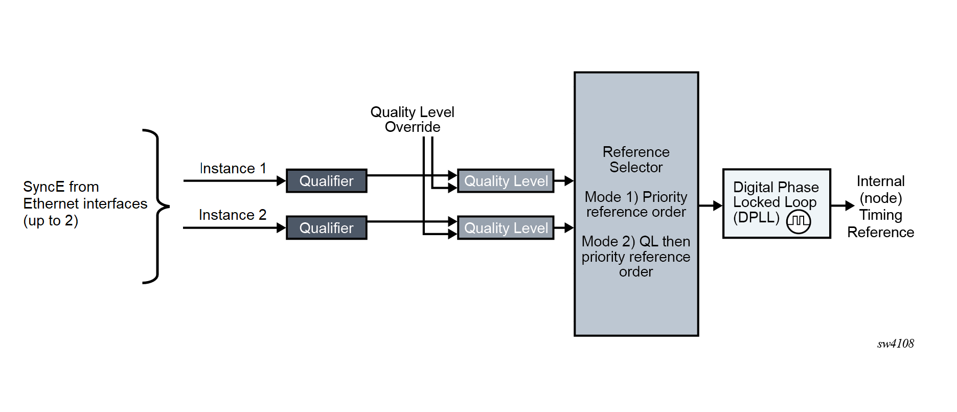
The central clock uses the available timing inputs to train its local oscillator. The priority order of these references must be specified using the instance 1 and instance 2 parameters. When the central CPM clock is locked, the clock output is able to drive the clocking on all line cards in the system.
The routers support the selection of node reference using Quality Level (QL) indications. The recovered clock is able to derive its timing from one of the references available on that platform.
The following figure illustrates synchronization reference selection. It shows how the recovered clock is able to derive the timing from Synchronous Ethernet ports.
The revert setting controls when the central clock can re-select a previously failed reference.
The following table describes the selection followed for two references in both revertive and non-revertive modes.
| Status of reference A | Status of reference B | Active reference non-revertive case | Active reference revertive case |
|---|---|---|---|
|
OK |
OK |
A |
A |
|
Failed |
OK |
B |
B |
|
OK |
OK |
B |
A |
|
OK |
Failed |
A |
A |
|
Failed |
Failed |
Holdover |
Holdover |
|
OK |
OK |
A or B |
A |
Supported synchronization options
The following table summarizes the synchronization options that are available.
| Synchronization option | Supported platform | Notes |
|---|---|---|
|
SyncE with SSM |
7220 IXR-D5; model 3HE17735AB (w/Timing) |
— |
|
1588/PTP with port-based timestamps |
7220 IXR-D5; model 3HE17735AB (w/Timing) |
— |
|
1pps interface |
7220 IXR-D5; model 3HE17735AB (w/Timing) |
Supported for output only |
Synchronization Status Message
Synchronization Status Messages (SSM) allow the synchronization distribution network to determine the quality level of the clock sourcing a specific synchronization trail, and to allow a network element to select the best of multiple input synchronization trails. SSM has been defined for synchronous Ethernet for interaction with office clocks, such as BITS or SSUs, and embedded network element clocks.
SSM allows equipment to autonomously provision and reconfigure (by reference switching) their synchronization references, while helping to avoid the creation of timing loops. These messages are particularly useful for synchronization re-configurations when timing is distributed in both directions around a ring.