EVPN for VXLAN tunnels (Layer 2)
This chapter describes the components of EVPN-VXLAN Layer 2 on SR Linux.
EVPN-VXLAN L2 basic configuration
Basic configuration of EVPN-VXLAN L2 on SR Linux consists of the following:
A vxlan-interface, which contains the ingress VNI of the incoming VXLAN packets associated with the vxlan-interface
A MAC-VRF network-instance, where the vxlan-interface is attached. Only one vxlan-interface can be attached to a MAC-VRF network-instance.
BGP-EVPN is also enabled in the same MAC-VRF with a minimum configuration of the EVI and the network-instance vxlan-interface associated with it.
The BGP instance under BGP-EVPN has an encapsulation-type leaf, which is VXLAN by default.
For EVPN, this determines that the BGP encapsulation extended community is advertised with value VXLAN and the value encoded in the label fields of the advertised NLRIs is a VNI.
If the route-distinguisher or route-target/policies are not configured, the required values are automatically derived from the configured EVI as follows:
The route-distinguisher is derived as
<ip-address:evi>, where theip-addressis the IPv4 address of the default network-instance sub-interface system0.0.The route-target is derived as
<asn:evi>, where theasnis the autonomous system configured in the default network-instance.
The following example shows a basic EVPN-VXLAN L2 configuration consisting of a vxlan-interface, MAC-VRF network-instance, and BGP-EVPN configuration:
--{ candidate shared default }--[ ]--
# info
...
    tunnel-interface vxlan1 {
        vxlan-interface 1 {
            type bridged
            ingress {
                vni 10
            }
            egress {
                source-ip use-system-ipv4-address
            }
        }
    }

// In the network-instance:

A:dut2#  network-instance blue
--{ candidate shared default }--[ network-instance blue ]--
# info
    type mac-vrf
    admin-state enable
    description "Blue network instance"
    interface ethernet-1/2.1 {
    }
    vxlan-interface vxlan1.1 {
    }
    protocols {
        bgp-evpn {
            bgp-instance 1 {
                admin-state enable
                vxlan-interface vxlan1.1
                evi 10
            }
        }
        bgp-vpn {
            bgp-instance 1 {
     // rd and rt are auto-derived from evi if this context is not configured
                export-policy pol-def-1
                import-policy pol-def-1
                route-distinguisher {
                    route-distinguisher 64490:200
                }
                route-target {
                    export-rt target:64490:200
                    import-rt target:64490:100
                }
            }
        }
    }
EVPN L2 basic routes
EVPN Layer 2 (without multi-homing) includes the implementation of the BGP-EVPN address family and support for the following route types:
EVPN MAC/IP route (or type 2, RT2)
EVPN Inclusive Multicast Ethernet Tag route (IMET or type 3, RT3)
The MAC/IP route is used to convey the MAC and IP information of hosts connected to subinterfaces in the MAC-VRF. The IMET route is advertised as soon as bgp-evpn is enabled in the MAC-VRF; it has the following purpose:
Auto-discovery of the remote VTEPs attached to the same EVI
Creation of a default flooding list in the MAC-VRF so that BUM frames are replicated
Advertisement of the MAC/IP and IMET routes is configured on a per-MAC-VRF basis. The following example shows the default setting advertise true, which advertises MAC/IP and IMET routes.
Note that changing the setting of the advertise parameter and committing the change internally flaps the BGP instance.
--{ candidate shared default }--[ network-instance blue protocols bgp-evpn bgp-
instance 1 ]--
# info detail
    admin-state enable
    vxlan-interface vxlan1.1
    evi 1
    ecmp 1
    default-admin-tag 0
    routes {
        next-hop use-system-ipv4-address
        mac-ip {
            advertise true
        }
        inclusive-mcast {
            advertise true
        }
    }
Creation of VXLAN destinations based on received EVPN routes
The creation of VXLAN destinations of type unicast, unicast ES (Ethernet Segment), and multicast for each vxlan-interface is driven by the reception of EVPN routes.
The created unicast, unicast ES, and multicast VXLAN destinations are visible in state. Each destination is allocated a system-wide unique destination index and is an internal NHG-ID (next-hop group ID). The destination indexes for the VXLAN destinations are shown in the following example for destination 10.22.22.4, vni 1
--{ [FACTORY] + candidate shared default }--[  ]--
# info from state tunnel-interface vxlan1 vxlan-interface 1 bridge-table unicast-
destinations destination * vni *
    tunnel-interface vxlan1 {
        vxlan-interface 1 {
            bridge-table {
                unicast-destinations {
                    destination 10.44.44.4 vni 1 {
                        destination-index 677716962904 // destination index
                        statistics {
                        }
                        mac-table {
                            mac 00:00:00:01:01:04 {
                                type evpn-static
                                last-update "16 hours ago"
                            }
                        }
                    }
                }
            }
        }
    }
--{ [FACTORY] + candidate shared default }--[  ]--
# info from state network-instance blue bridge-table mac-table mac 00:00:00:01:01:04
    network-instance blue {
        bridge-table {
            mac-table {
                mac 00:00:00:01:01:04 {
                    destination-type vxlan
                    destination-index 677716962904 // destination index
                    type evpn-static
                    last-update "16 hours ago"
                    destination "vxlan-interface:vxlan1.1 vtep:10.44.44.4 vni:1"
                }
            }
        }
    }
The following is an example of dynamically created multicast destinations for a vxlan-interface:
--{ [FACTORY] + candidate shared default }--[  ]--
A:dut1# info from state tunnel-interface vxlan1 vxlan-interface 1 bridge-
table multicast-destinations
    tunnel-interface vxlan1 {
        vxlan-interface 1 {
            bridge-table {
                multicast-destinations {
                    destination 40.1.1.2 vni 1 {
                        multicast-forwarding BUM
                        destination-index 46428593833
                    }
                    destination 40.1.1.3 vni 1 {
                        multicast-forwarding BUM
                        destination-index 46428593835
                    }
                    destination 40.1.1.4 vni 1 {
                        multicast-forwarding BUM
                        destination-index 46428593829
                    }
                }
            }
        }
    }
EVPN route selection
When a MAC is received from multiple sources, the route is selected based on the priority listed in MAC selection. Learned and EVPN-learned routes have equal priority; the latest received route is selected.
When multiple EVPN-learned MAC/IP routes arrive for the same MAC but with a different key (for example, two routes for MAC M1 with different route-distinguishers), a selection is made based on the following priority:
EVPN MACs with higher SEQ number
EVPN MACs with lower IP next-hop
EVPN MACs with lower Ethernet Tag
EVPN MACs with lower RD
BGP next hop configuration for EVPN routes
You can configure the BGP next hop to be used for the EVPN routes advertised for a network-instance. This next hop is by default the IPv4 address configured in interface system 0.0 of the default network-instance. However, the next-hop address can be changed to any IPv4 address.
The system does not check that the configured IP address exists in the default network-instance. Any valid IP address can be used as next hop of the EVPN routes advertised for the network-instance, irrespective of its existence in any subinterface of the system. However, the receiver leaf nodes create their unicast, multicast and ES destinations to this advertised next-hop, so it is important that the configured next-hop is a valid IPv4 address that exists in the default network-instance.
When the system or loopback interface configured for the BGP next-hop is administratively disabled, EVPN still advertises the routes, as long as a valid IP address is available for the next-hop. However, received traffic on that interface is dropped.
The following example configures a BGP next hop to be used for the EVPN routes advertised for a network-instance.
--{ candidate shared default }--[ network-instance 1 protocols bgp-evpn bgp-
instance 1 ]--
# info
    routes {
        next-hop 1.1.1.1
        }
    }
MAC duplication detection for Layer 2 loop prevention in EVPN
MAC loop prevention in EVPN broadcast domains is based on the SR Linux MAC duplication feature (see MAC duplication detection and actions), but considers MACs that are learned via EVPN as well. The feature detects MAC duplication for MACs moving among bridge subinterfaces of the same MAC-VRF, as well as MACs moving between bridge subinterfaces and EVPN in the same MAC-VRF, but not for MACs moving from a VTEP to a different VTEP (via EVPN) in the same MAC-VRF.
Also, when a MAC is declared as duplicate, and the blackhole configuration option is added to the interface, then not only incoming frames on bridged subinterfaces are discarded if their MAC SA or DA match the blackhole MAC, but also frames encapsulated in VXLAN packets are discarded if their source MAC or destination MAC match the blackhole MAC in the mac-table.
When a MAC exceeds the allowed num-moves, the MAC is moved to a type duplicate (irrespective of the type of move: EVPN-to-local, local-to-local, local-to-EVPN), the EVPN application receives an update that advertises the MAC with a higher sequence number (which may trigger the duplication in other nodes). The ‟duplicate” MAC can be overwritten by a higher priority type, or flushed by the tools command (see Deleting entries from the bridge table).
EVPN L2 multi-homing
SR Linux supports single-active multi-homing and all-active multi-homing, as defined in RFC 7432. The EVPN multi-homing implementation uses the following SR Linux features:
System network-instance
A system network-instance container hosts the configuration and state of EVPN for multi-homing.
BGP network-instance
The ES model uses a BGP instance from where the RD/RT and export/import policies are taken to advertise and process the multi-homing ES routes. Only one BGP instance is allowed, and all the ESes are configured under this BGP instance. The RD/RTs cannot be configured when the BGP instance is associated with the system network-instance; however the operational RD/RTs are still shown in state.
Ethernet Segments
An ES has an admin-state (disabled by default) setting that must be toggled to change any of the parameters that affect the EVPN control plane. In particular, the ESes support the following:
General and per-ES boot and activation timers.
Manual 10-byte ESI configuration.
All-active and single-active multi-homing modes.
DF Election algorithm type Default (modulo based) or type Preference.
Configuration of ES and AD per-ES routes next-hop, and ES route originating-IP per ES.
An AD per ES route is advertised per mac-vrf, where the route carries the network-instance RD and RT.
Association with an interface that can be of type Ethernet or LAG. When associated with a LAG, the LAG can be static or LACP-based. In case of LACP, the same system-id/system-priority/port-key settings must be configured on all the nodes attached to the same ES.
Aliasing load balancing
This hashing operation for aliasing load balancing uses the following hash fields in the incoming frames by default:
For IP traffic: IP DA and IP SA, Layer 4 source and destination ports, protocol, VLAN ID.
For Ethernet (non-IP) traffic: MAC DA and MAC SA, VLAN ID, Ethertype.
For IPv6 addresses, 32 bit fields are generated by XORing and Folding the 128 bit address. The packet fields are supplied as input to the hashing computation.
Reload-delay timer
The reload-delay timer configures an interface to be shut down for a period of time following a node reboot or an IMM reset to avoid black-holing traffic.
EVPN L2 multi-homing procedures
EVPN relies on three different procedures to handle multi-homing: DF election, split-horizon, and aliasing. DF election is relevant to single-active and all-active multi-homing; split-horizon and aliasing are relevant only to all-active multi-homing.
DF Election – The Designated Forwarder (DF) is the leaf that forwards BUM traffic in the ES. Only one DF can exist per ES at a time, and it is elected based on the exchange of ES routes (type 4) and the subsequent DF Election Algorithm (DF Election Alg).
In single-active multi-homing, the non-DF leafs bring down the subinterface associated with the ES.
In all-active multi-homing, the non-DF leafs do not forward BUM traffic received from remote EVPN PEs.
Split-horizon – This is the mechanism by which BUM traffic received from a peer ES PE is filtered so that it is not looped back to the CE that first transmitted the frame. Local bias is applied in VXLAN services, as described in RFC 8365.
Aliasing – This is the procedure by which PEs that are not attached to the ES can process non-zero ESI MAC/IP routes and AD routes and create ES destinations to which per-flow ECMP can be applied.
To support multi-homing, EVPN-VXLAN supports two additional route types:
ES routes (type 4) – Used for ES discovery on all the leafs attached to the ES and DF Election.
ES routes use an ES-import route target extended community (its value is derived from the ESI), so that its distribution is limited to only the leafs that are attached to the ES.
The ES route is advertised with the DF Election extended community, which indicates the intent to use a specific DF Election Alg and capabilities.
Upon reception of the remote ES routes, each PE builds a DF candidate list based on the originator IP of the ES routes. Then, based on the agreed DF Election Alg, each PE elects one of the candidates as DF for each mac-vrf where the ES is defined.
AD route (type 1) – Advertised to the leafs attached to an ES. There are two versions of AD routes:
AD per-ES route – Used to advertise the multi-homing mode (single-active or all-active) and the ESI label, which is not advertised or processed in case of VXLAN. Its withdrawal enables the mass withdrawal procedures in the remote PEs.
AD per-EVI route – Used to advertise the availability of an ES in an EVI and its VNI. It is needed by the remote leafs for the aliasing procedures.
Both versions of AD routes can influence the DF Election. Their withdrawal from a leaf results in removing that leaf from consideration for DF Election for the associated EVI, as long as ac-df exclude is configured. (The AC-DF capability can be set to exclude only if the DF election algorithm type is set to preference.)
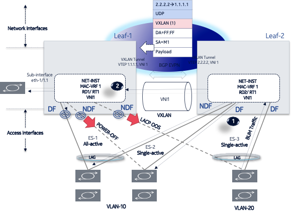
EVPN-VXLAN local bias for all-active multi-homing
Local bias for all-active multi-homing is based on the following behavior at the ingress and egress leafs:
At the ingress leaf, any BUM traffic received on an all-active multi-homing LAG subinterface (associated with an EVPN-VXLAN mac-vrf) is flooded to all local subinterfaces, irrespective of their DF or NDF status, and VXLAN tunnels.
At the egress leaf, any BUM traffic received on a VXLAN subinterface (associated with an EVPN-VXLAN mac-vrf) is flooded to single-homed subinterfaces and multi-homed subinterfaces whose ES is not shared with the owner of the source VTEP if the leaf is DF for the ES.
In SR Linux, the local bias filtering entries on the egress leaf are added or removed based on the ES routes, and they are not modified by the removal of AD per EVI/ES routes. This may cause blackholes in the multi-homed CE for BUM traffic if the local subinterfaces are administratively disabled.
Single-active multi-homing
EVPN L2 single-homing configuration shows a single-active ES attached to two leaf nodes. In this configuration, the ES in single-active mode can be configured to do the following:
Associate to an Ethernet interface or a LAG interface (as all-active ESes)
Coexist with all-active ESes on the same node, as well as in the same MAC-VRF service.
Signal the non-DF state to the CE by using LACP out-of-synch signaling or power off.
Optionally, the ES can be configured not to signal to the CE. When the LACP synch flag or power off is used to signal the non-DF state to the CE/server, all of the subinterfaces are active on the same node; that is, load balancing is not per-service, but rather per-port. This mode of operation is known as EVPN multi-homing port-active mode.
Connect to a CE that uses a single LAG to connect to the ES or separate LAG/ports per leaf in the ES.
All peers in the ES must be configured with the same multi-homing mode; if the nodes are not
configured consistently, the oper-multi-homing-mode in state is
single-active. From a hardware resource perspective, no local-bias-table entries are
populated for ESes in single-active mode.
The following features work in conjunction with single-active mode:
Preference-based DF election / non-revertive option configures ES peers to elect a DF based on a preference value, as well as an option to prevent traffic from reverting back to a former DF node.
Attachment Circuit influenced DF Election (AC-DF) allows the DF election candidate list for a network-instance to be modified based on the presence of the AD per-EVI and per-ES routes.
Standby LACP-based or power-off signaling configures how the node’s non-DF state is signaled to the multi-homed CE.
Preference-based DF election / non-revertive option
Preference-based DF election is defined in draft-ietf-bess-evpn-pref-df and specifies a way for the ES peers to elect a DF based on a preference value (highest preference-value wins). The draft-ietf-bess-evpn-pref-df document also defines a non-revertive mode, so that upon recovery of a former DF node, traffic does not revert to the node. This is desirable in most cases to avoid double impact on the traffic (failure and recovery).
The configuration requires the command df-election/algorithm/type preference and the corresponding df-election/algorithm/preference-alg/preference-value. Optionally, you can set non-revertive mode to true. See EVPN multi-homing configuration example.
All of the peers in the ES should be configured with the same algorithm type. However, if that is not the case, all the peers fall back to the default algorithm/oper-type.
Attachment Circuit influenced DF Election (AC-DF)
AC-DF refers to the ability to modify the DF election candidate list for a network-instance based on the presence of the AD per-EVI and per-ES routes. When enabled (ac-df include command), a node cannot become DF if it has the ES subinterface in administratively disabled state. The AC-DF capability is defined in RFC 8584, and it is by default enabled.
The AC-DF capability should be disabled (ac-df exclude command) when single-active multi-homing is used and standby-signaling (lacp power-off command) signals the non-DF state to the multi-homed CE/server. In this case, the same node must be DF for all the contained subinterfaces. Administratively disabling one subinterface does not cause a DF switchover for the network-instance if ac-df exclude is configured.
The AC-DF capability is configured with the command df-election algorithm preference-alg capabilities ac-df; include is the default. See EVPN multi-homing configuration example.
Standby LACP-based or power-off signaling
Standby LACP-based or power-off signaling is used for cases where the AC-DF capability is excluded, and the DF election port-active mode is configured.
When single-active multi-homing is used and all subinterfaces on the node for the ES must be in DF or non-DF state, the multi-homed CE should not send traffic to the non-DF node. SR Linux supports two ways of signaling the non-DF state to the multi-homed CE: LACP standby or power-off.
Signaling the non-DF state is configured at the interface level, using the command interface ethernet standby-signaling, and must also be enabled for a specific ES using the ethernet-segment df-election interface-standby-signaling-on-non-df command. See EVPN multi-homing configuration example.
The LACP signaling method is only available on LAG interfaces with LACP enabled. When the node is in non-DF state, it uses an LACP out-of-synch notification (the synch bit is clear in the LACP PDUs) to signal the non-DF state to the CE. The CE then brings down LACP, and the system does not jump to the collecting-distributing state, and neither does the peer (because of out_of_sync). After the port is out of standby mode, LACP needs to be re-established, and the forwarding ports need to be programmed after that.
The power-off signaling is available on Ethernet and LAG interfaces. When the node is in non-DF
state, the interface goes oper-down, and the lasers on the Ethernet interfaces (all
members in case of a LAG) are turned off. This brings the CE interface down and avoids
any traffic on the link. The interfaces state show oper-state down and
oper-down-reason standby-signaling.
Reload-delay timer
After the system boots, the reload-delay timer keeps an interface shut down with the laser off for a configured amount of time until connectivity with the rest of network is established. When applied to an access multi-homed interface (typically an Ethernet Segment interface), this delay can prevent black-holing traffic coming from the multi-homed server or CE.
In EVPN multi-homing scenarios, if one leaf in the ES peer group is rebooting, coming up after an upgrade or a failure, it is important for the ES interface not to become active until after the node is ready to forward traffic to the core. If the ES interface comes up too quickly and the node has not programmed its forwarding tables yet, traffic from the server is black-holed. To prevent this from happening, you can configure a reload-delay timer on the ES interface so that the interface does not become active until after network connectivity is established.
When a reload-delay timer is configured, the interface port is shut down and the laser is turned off from the time that the system determines the interface state following a reboot or reload of the XDP process, until the number of seconds specified in the reload-delay timer elapse.
The reload-delay timer is only supported on Ethernet interfaces that are not enabled with breakout mode. For a multi-homed LAG interface, the reload-delay timer should be configured on all the interface members. The reload-delay timer can be from 1-86,400 seconds. There is no default value; if not configured for an interface, there is no reload-delay timer.
Only ES interfaces should be configured with a non-zero reload-delay timer. Single-homed interfaces and network interfaces (used to forward VXLAN traffic) should not have a reload-delay timer configured.
The following example sets the reload-delay timer for an interface to 20 seconds. The timer starts following a system reboot or when the IMM is reconnected, and the system determines the interface state. During the timer period, the interface is deactivated and the port laser is inactive.
--{ * candidate shared default }--[  ]--
# info interface ethernet-1/1
    interface ethernet-1/1 {
        admin-state enable
        ethernet {
            reload-delay 20
        }
    }
When the reload-delay timer is running, the port-oper-down-reason for the port
is shown as interface-reload-timer-active. The
reload-delay-expires state indicates the amount of time remaining
until the port becomes active. For example:
--{ * candidate shared default }--[  ]--
# info from state interface ethernet-1/1
    interface ethernet-1/1 {
        description eth_seg_1
        admin-state enable
        mtu 9232
        loopback-mode false
        ifindex 671742
        oper-state down
        oper-down-reason interface-reload-time-active
        last-change "51 seconds ago"
        vlan-tagging true
        ...
        ethernet {
            auto-negotiate false
            lacp-port-priority 32768
            port-speed 100G
            hw-mac-address 00:01:01:FF:00:15
            reload-delay 20
            reload-delay-expires "18 seconds from now"
            flow-control {
                receive false
                transmit false
            }
        }
    }
EVPN multi-homing configuration example
The following is an example of a single-active multi-homing configuration, including standby signaling power-off, AC-DF capability, and preference-based DF algorithm.
The following configures power-off signaling and the reload delay timer for an interface:
--{ * candidate shared default }--[  ]--
# info interface ethernet-1/21 ethernet
    standby-signaling power-off // needed to signal non-DF state to the CE
    reload-delay 100 // upon reboot, this is required to avoid attracting traffic
from the multi-homed CE until the node is ready to forward.
// The time accounts for the time it takes all network protocols to be up
and forwarding entries ready.
The following configures DF election settings for the ES, including preference-based DF election and a preference value for the DF election alg. The ac-df setting is set to exclude, which disables the AC-DF capability. The non-revertive option is enabled, which prevents traffic from reverting back to a former DF node when the node reconnects to the network.
--{ * candidate shared default }--[ system network-instance protocols evpn ethernet-
segments bgp-instance 1 ethernet-segment eth_seg_1 ]--
# info
    admin-state enable
    esi 00:01:00:00:00:00:00:00:00:00
    interface ethernet-1/21
    multi-homing-mode single-active
    df-election {
        interface-standby-signaling-on-non-df { // presence container that enables
the standby-signaling for the ES
        }
        algorithm {
            type preference // enables the use of preference based DF election
            preference-alg {
                preference-value 100 // changes the default 32767 to a
specific value
                capabilities {
                    ac-df exclude // turns off the default ac-df capability
                    non-revertive true // enables the non-revertive mode
                }
            }
        }
    }
The following shows the state (and consequently the configuration) of an ES for single-active multi-homing and indicates the default settings for the algorithm/oper-type. All of the peers in the ES should be configured with the same algorithm type. However, if that is not the case, all the peers fall back to the default algorithm.
--{ * candidate shared default }--[ system network-instance protocols evpn ethernet-
segments bgp-instance 1 ethernet-segment eth_seg_1 ]--
# info
    admin-state enable
    oper-state up
    esi 00:01:00:00:00:00:00:00:00:00
    interface ethernet-1/21
    multi-homing-mode single-active
    oper-multi-homing-mode single-active // oper mode may be different if not all
the ES peers are configured in the same way
    df-election {
        interface-standby-signaling-on-non-df {
        }
        algorithm {
            type preference
            oper-type preference // if at least one peer in the ES is in type
default, all the peers will fall back to default
            preference-alg {
                preference-value 100
                capabilities {
                    ac-df exclude
                    non-revertive true
                }
            }
        }
    }
    routes {
        next-hop use-system-ipv4-address
        ethernet-segment {
            originating-ip use-system-ipv4-address
        }
    }
    association {
        network-instance blue {
            bgp-instance 1 {
                designated-forwarder-role-last-change "2 seconds ago"
                designated-forwarder-activation-start-time "2 seconds ago"
                designated-forwarder-activation-time 3
                computed-designated-forwarder-candidates {
                    designated-forwarder-candidate 40.1.1.1 {
                        add-time "2 seconds ago"
                        designated-forwarder true
                    }
                    designated-forwarder-candidate 40.1.1.2 {
                        add-time "2 minutes ago"
                        designated-forwarder false
                    }
                }
            }
        }
    }
}
To display information about the ES, use the show system network-instance ethernet-segments command. For example:
--{ [FACTORY] + candidate shared default }--[  ]--
# show system network-instance ethernet-segments eth_seg_1
------------------------------------------------------------------------------------
eth_seg_1 is up, single-active
  ESI      : 00:01:00:00:00:00:00:00:00:00
  Alg      : preference
  Peers    : 40.1.1.2
  Interface: ethernet-1/21
  Network-instances:
     blue
      Candidates : 40.1.1.1 (DF), 40.1.1.2
      Interface : ethernet-1/21.1
------------------------------------------------------------------------------------
Summary
 1 Ethernet Segments Up
 0 Ethernet Segments Down
------------------------------------------------------------------------------------
The detail option displays more information about the ES. For example:
--{ [FACTORY] + candidate shared default }--[  ]--
# show system network-instance ethernet-segments eth_seg_1 detail
====================================================================================
Ethernet Segment
====================================================================================
Name                 : eth_seg_1
40.1.1.1 (DF)
Admin State          : enable              Oper State        : up
ESI                  : 00:01:00:00:00:00:00:00:00:00
Multi-homing         : single-active          Oper Multi-homing : single-active
Interface            : ethernet-1/21
ES Activation Timer  : None
DF Election          : preference          Oper DF Election  : preference

Last Change          : 2021-04-06T08:49:44.017Z
====================================================================================
 MAC-VRF    Actv Timer Rem   DF
eth_seg_1   0                Yes
------------------------------------------------------------------------------------
DF Candidates
------------------------------------------------------------------------------------
Network-instance       ES Peers
blue                   40.1.1.1 (DF)
blue                   40.1.1.2
====================================================================================
On the DF node, the info from state command displays the following:
--{ [FACTORY] + candidate shared default }--[  ]--
# info from state interface ethernet-1/21 | grep oper
        oper-state up
            oper-state not-present
            oper-state up

--{ [FACTORY] + candidate shared default }--[  ]--
# info from state network-instance blue interface ethernet-1/21.1
    network-instance blue {
        interface ethernet-1/21.1 {
            oper-state up
            oper-mac-learning up
            index 6
            multicast-forwarding BUM
        }
    }
On the non-DF node, the info from state command displays the following:
--{ [FACTORY] + candidate shared default }--[  ]--
# info from state interface ethernet-1/21 | grep oper
        oper-state down
        oper-down-reason standby-signaling
            oper-state not-present
            oper-state down
            oper-down-reason port-down

--{ [FACTORY] + candidate shared default }--[  ]--
# info from state network-instance blue interface ethernet-1/21.1
    network-instance blue {
        interface ethernet-1/21.1 {
            oper-state down
            oper-down-reason subif-down
            oper-mac-learning up
            index 7
            multicast-forwarding none
        }
    }