EVPN configuration examples
This chapter contains examples of configurations that use EVPN features.
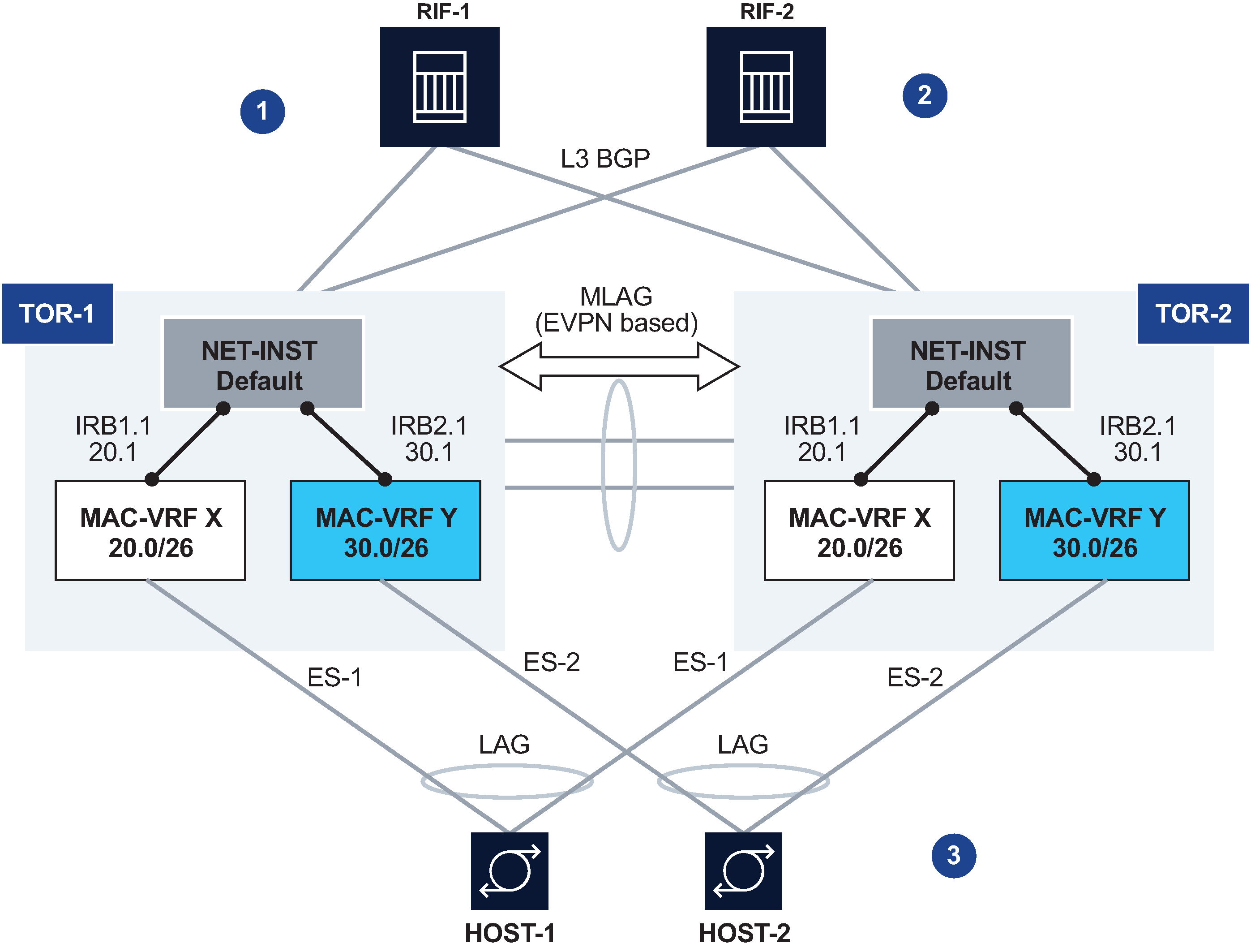
All-active redundant connectivity example
Active-active connectivity example shows an example of using EVPN multi-homing as a standalone and self-contained multi-chassis solution.
This example uses the following features:
Redundancy
TOR redundancy is based on an all-active redundancy model.
Layer 3 connectivity
An anycast gateway solution is used on the IRB subinterfaces so that upstream traffic is always routed locally on the TOR receiving the traffic.
South-to-north traffic is sent to the active link and routed by the local IRB subinterface. In case of failure on TOR-1, TOR-2 is ready to forward on the anycast gateway IRB, without the need to wait for any VRRP protocol to converge.
North-to-south traffic is load-balanced by the fabric to the two TORs. ARP/ND entries are synchronized across both TORs. Host routes could be optionally created and advertised in BGP from the directly connected TOR to avoid tromboning in the downstream direction.
Layer 2 connectivity
Servers do not need to run any xSTP protocols. The NDF TOR brings down the port and signals LOS to the server.
This solution places no requirements on the servers.
This example imposes the use of a LAG on the server. The LAG can use LACP or not. The servers are unaware that the LAG is connected to two systems instead of only one.
Configuration for all-active connectivity example
Leaf 1 in Active-active connectivity example has the following configuration. Leaf 2 would have an equivalent configuration.
--{ [FACTORY] +* candidate shared default }--[  ]--
A:Leaf-1#
// two IRB interfaces with anycast-gw configuration is added
interface irb1 {
    subinterface 1 {
        ipv4 {
            address 20.0.0.1/24 {
                anycast-gw true
                primary
            }
            arp {
                learn-unsolicited true
                evpn {
                    advertise dynamic {
                    }
                }
            }
        }
        anycast-gw {
        }
    }
}
interface irb2 {
    subinterface 1 {
        ipv4 {
            address 30.0.0.1/24 {
                anycast-gw true
                primary
            }
            arp {
                learn-unsolicited true
                evpn {
                    advertise dynamic {
                    }
                }
            }
        }
        anycast-gw {
        }
    }
}
// lags associated with the ethernet-segments.
 In this case static, but they can be lacp based too.
interface lag1 {
    admin-state enable
    vlan-tagging true
    subinterface 1 {
        vlan {
            encap {
                single-tagged {
                    vlan-id 20
                }
            }
        }
    }
    lag {
        lag-type static
    }
}
interface lag2 {
    admin-state enable
    vlan-tagging true
    subinterface 1 {
        vlan {
            encap {
                single-tagged {
                    vlan-id 30
                }
            }
        }
    }
    lag {
        lag-type static
    }
}
// ES configuration
system {
    network-instance {
        protocols {
            evpn {
                ethernet-segments {
                    bgp-instance 1 {
                        ethernet-segment ES-1 {
                            admin-state enable
                            esi 00:01:00:00:00:00:00:00:00:01
                            interface lag1
                        }
                        ethernet-segment ES-2 {
                            admin-state enable
                            esi 00:02:00:00:00:00:00:00:00:02
                            interface lag2
                        }
                    }
                }
            }
        }
    }
}
// MAC-VRFs
network-instance MAC-VRF-X {
    type mac-vrf
    admin-state enable
    interface irb1.1 {
    }
    interface lag1.1 {
    }
    vxlan-interface vxlan1.20 {
    }
    protocols {
        bgp-evpn {
            bgp-instance 1 {
                admin-state enable
                vxlan-interface vxlan1.20
                evi 20
            }
        }
        bgp-vpn {
            bgp-instance 1 {
            }
        }
    }
}
network-instance MAC-VRF-Y {
    type mac-vrf
    admin-state enable
    interface irb2.1 {
    }
    interface lag2.1 {
    }
    vxlan-interface vxlan1.30 {
    }
    protocols {
        bgp-evpn {
            bgp-instance 1 {
                admin-state enable
                vxlan-interface vxlan1.30
                evi 30
            }
        }
        bgp-vpn {
            bgp-instance 1 {
            }
        }
    }
}
// default network-instance configuration
network-instance default {
    type default
    admin-state enable
    description "Default network instance"
    router-id 1.1.1.1
    interface ethernet-1/1.1 {
    }
    interface ethernet-1/20.1 {
    }
    interface irb1.1 {
    }
    interface irb2.1 {
    }
    interface system0.0 {
    }
    protocols {
        bgp {
            admin-state enable
            autonomous-system 1234
            router-id 1.1.1.1
            group eBGP-spines {
                admin-state enable
                export-policy export-all
                peer-as 4567
                ipv4-unicast {
                    admin-state enable
                }
            }
            group evpn-mh {
                admin-state enable
                export-policy export-all
                peer-as 1234
                evpn {
                    admin-state enable
                }
            }
            neighbor 2.2.2.2 {
                admin-state enable
                peer-group evpn-mh
            }
            neighbor 10.1.4.4 {
                admin-state enable
                peer-group eBGP-spines
            }
        }
    }
}
// vxlan interfaces for the MH configuration
tunnel-interface vxlan1 {
    vxlan-interface 20 {
        type bridged
        ingress {
            vni 20
        }
    }
    vxlan-interface 30 {
        type bridged
        ingress {
            vni 30
        }
    }
}
Hierarchical active-active connectivity example
Hierarchical active-active connectivity example shows an example that makes use of a Layer 2 and a Layer 3 multi-homing solution.
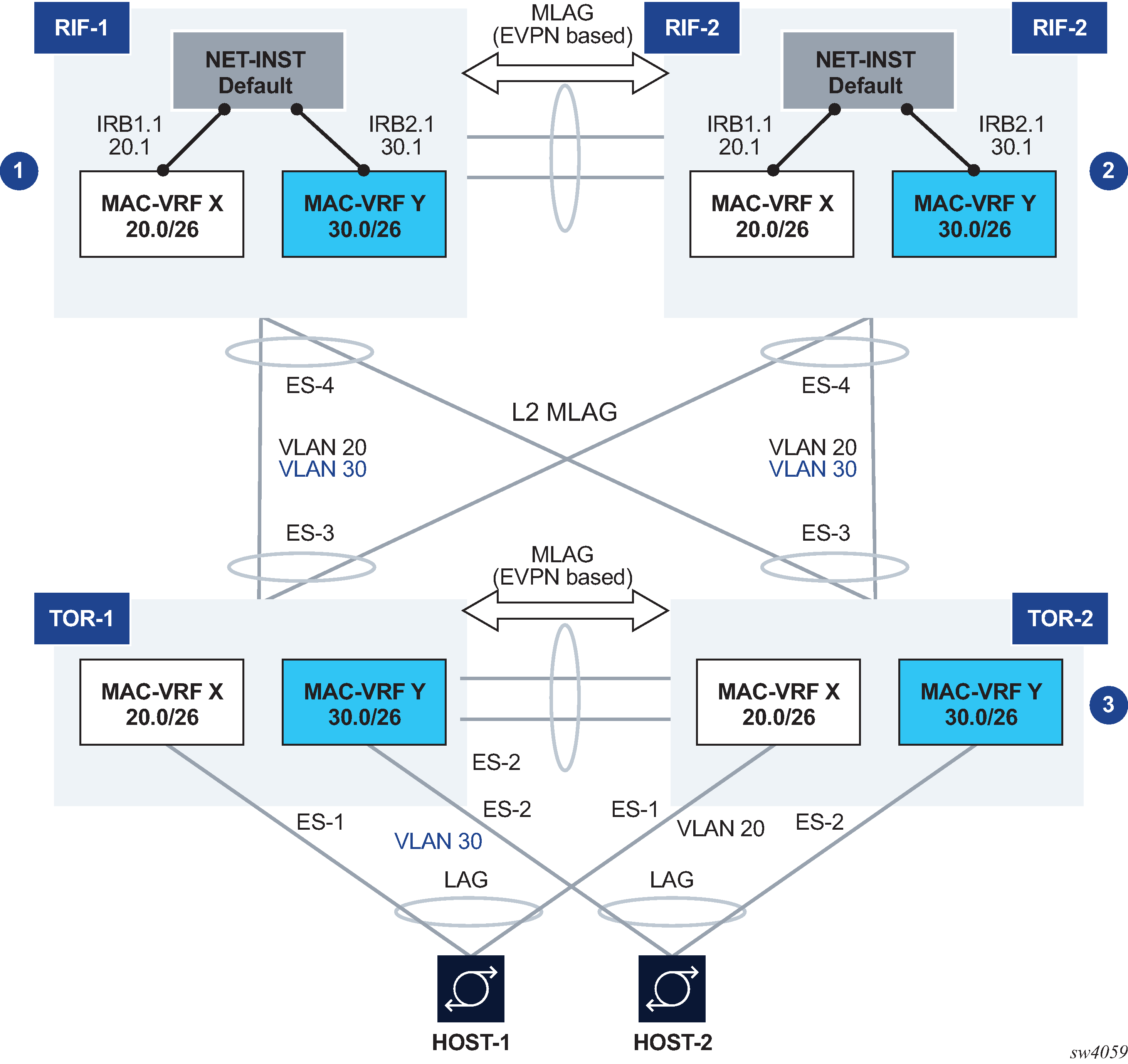
This example uses the following features:
Leaf / Spine configuration
There are two multi-chassis pairs at the Leaf and the Spine levels.
The Leaf pair runs all-active multi-homing on its own Ethernet Segments.
The access hosts or Spines are separate and independent Ethernet Segments. The diagram shows three Ethernet Segments, one per host at the access, and one for the connectivity to the Spine layer (note this is only one ES in spite of the number of Spine nodes, which could be 2 or 4).
The Spine layer runs all-active multi-homing with a single Ethernet Segment to the Leaf layer (associated with the LAG attached to the Leaf layer).
The two tiers are independent; there are no control plane protocols between them, except for LACP if used.
This means that the Leaf and Spine layer could theoretically be of a different vendor.
Layer 3 connectivity
An anycast gateway solution is used on the Spine layer, on the IRB subinterfaces, so that upstream traffic is always routed locally on the Leaf receiving the traffic.
South-to-north flows are sent to only one link at a time, so there is not duplication.
North-to-south traffic is load-balanced by the fabric to the two Spines and for the Spines load-balanced to the Leafs. ARP/ND entries are synchronized across both Spines. Host routes can optionally be created and advertised in BGP from the directly connected Spine to avoid tromboning in the downstream direction.
Layer 2 connectivity
Hosts are running LAG with or without LACP.
Leafs and Spines are connected by standard Layer 2 LAGs that carry the VLANs for the two broadcast domains illustrated in Hierarchical active-active connectivity example.
Configuration for hierarchical active-active connectivity example
Spine 1 in Hierarchical active-active connectivity example has the following configuration. The configuration for Spine 2 would be equivalent.
--{ [FACTORY] +* candidate shared default }--[  ]--
A:Spine-1#
// two IRB interfaces with anycast-gw configuration is added
interface irb1 {
    subinterface 1 {
        ipv4 {
            address 20.0.0.1/24 {
                anycast-gw true
                primary
            }
            arp {
                learn-unsolicited true
                evpn {
                    advertise dynamic {
  // for ARP synchronization across MH leaf nodes
                    }
                }
            }
        }
        anycast-gw {
        }
    }
}
interface irb2 {
    subinterface 1 {
        ipv4 {
            address 30.0.0.1/24 {
                anycast-gw true
                primary
            }
            arp {
                learn-unsolicited true
                evpn {
                    advertise dynamic {
                    }
                }
            }
        }
        anycast-gw {
        }
    }
}
// lags associated with the ethernet-segment.
 In this case static, but they can be lacp based too.
interface lag1 {
    admin-state enable
    vlan-tagging true
    subinterface 1 {
        vlan {
            encap {
                single-tagged {
                    vlan-id 20
                }
            }
        }
    }
    subinterface 2 {
        vlan {
            encap {
                single-tagged {
                    vlan-id 30
                }
            }
        }
    }
    lag {
        lag-type static
    }
}
// ES configuration
system {
    network-instance {
        protocols {
            evpn {
                ethernet-segments {
                    bgp-instance 1 {
                        ethernet-segment ES-4 {
                            admin-state enable
                            esi 00:44:44:44:44:44:44:00:00:04
                            interface lag1
                        }
                    }
                }
            }
        }
    }
}
// MAC-VRFs
network-instance MAC-VRF-X {
    type mac-vrf
    admin-state enable
    interface irb1.1 {
    }
    interface lag1.1 {
    }
    vxlan-interface vxlan1.20 {
    }
    protocols {
        bgp-evpn {
            bgp-instance 1 {
                admin-state enable
                vxlan-interface vxlan1.20
                evi 20
            }
        }
        bgp-vpn {
            bgp-instance 1 {
            }
        }
    }
}
network-instance MAC-VRF-Y {
    type mac-vrf
    admin-state enable
    interface irb2.1 {
    }
    interface lag1.2 {
    }
    vxlan-interface vxlan1.30 {
    }
    protocols {
        bgp-evpn {
            bgp-instance 1 {
                admin-state enable
                vxlan-interface vxlan1.30
                evi 30
            }
        }
        bgp-vpn {
            bgp-instance 1 {
            }
        }
    }
}
// default network-instance configuration
network-instance default {
    type default
    admin-state enable
    description "Default network instance"
    router-id 1.1.1.1
    interface ethernet-1/1.1 {
    }
    interface ethernet-1/20.1 {
    }
    interface irb1.1 {
    }
    interface irb2.1 {
    }
    interface system0.0 {
    }
    protocols {
        bgp {
            admin-state enable
            autonomous-system 1234
            router-id 1.1.1.1
            group eBGP-spines {
                admin-state enable
                export-policy export-all
                peer-as 4567
                ipv4-unicast {
                    admin-state enable
                }
            }
            group evpn-mh {
                admin-state enable
                export-policy export-all
                peer-as 1234
                evpn {
                    admin-state enable
                }
            }
            neighbor 2.2.2.2 {
                admin-state enable
                peer-group evpn-mh
            }
            neighbor 10.1.4.4 {
                admin-state enable
                peer-group eBGP-spines
            }
        }
    }
}
// vxlan interfaces for the MH configuration
tunnel-interface vxlan1 {
    vxlan-interface 20 {
        type bridged
        ingress {
            vni 20
        }
    }
    vxlan-interface 30 {
        type bridged
        ingress {
            vni 30
        }
    }
}
Leaf 1 in Hierarchical active-active connectivity example has the following configuration. The configuration for Leaf 2 would be equivalent.
--{ [FACTORY] +* candidate shared default }--[  ]--
A:Leaf-1#
// lags associated with the ethernet-segments.
 In this case static, but they can be lacp based too.
interface lag1 {
    admin-state enable
    vlan-tagging true
    subinterface 1 {
        vlan {
            encap {
                single-tagged {
                    vlan-id 20
                }
            }
        }
    }
    lag {
        lag-type static
    }
}
interface lag2 {
    admin-state enable
    vlan-tagging true
    subinterface 1 {
        vlan {
            encap {
                single-tagged {
                    vlan-id 30
                }
            }
        }
    }
    lag {
        lag-type static
    }
}
interface lag3 {
    admin-state enable
    vlan-tagging true
    subinterface 1 {
        vlan {
            encap {
                single-tagged {
                    vlan-id 20
                }
            }
        }
    }
    subinterface 2 {
        vlan {
            encap {
                single-tagged {
                    vlan-id 30
                }
            }
        }
    }
    lag {
        lag-type static
    }
}
// ES configuration
system {
    network-instance {
        protocols {
            evpn {
                ethernet-segments {
                    bgp-instance 1 {
                        ethernet-segment ES-1 {
                            admin-state enable
                            esi 00:11:11:11:11:11:11:00:00:01
                            interface lag1
                        }
                        ethernet-segment ES-2 {
                            admin-state enable
                            esi 00:22:22:22:22:22:22:00:00:02
                            interface lag2
                        }
                        ethernet-segment ES-3 {
                            admin-state enable
                            esi 00:33:33:33:33:33:33:00:00:03
                            interface lag3
                        }
                    }
                }
            }
        }
    }
}
// MAC-VRFs
network-instance MAC-VRF-X {
    type mac-vrf
    admin-state enable
    interface lag1.1 {
    }
    interface lag3.1 {
    }
    vxlan-interface vxlan1.20 {
    }
    protocols {
        bgp-evpn {
            bgp-instance 1 {
                admin-state enable
                vxlan-interface vxlan1.20
                evi 20
            }
        }
        bgp-vpn {
            bgp-instance 1 {
            }
        }
    }
}
network-instance MAC-VRF-Y {
    type mac-vrf
    admin-state enable
    interface lag2.1 {
    }
    interface lag3.1 {
    }
    vxlan-interface vxlan1.30 {
    }
    protocols {
        bgp-evpn {
            bgp-instance 1 {
                admin-state enable
                vxlan-interface vxlan1.30
                evi 30
            }
        }
        bgp-vpn {
            bgp-instance 1 {
            }
        }
    }
}
// default network-instance configuration
network-instance default {
    type default
    admin-state enable
    description "Default network instance"
    router-id 1.1.1.1
    interface ethernet-1/1.1 {
    }
    interface system0.0 {
    }
    protocols {
        bgp {
            admin-state enable
            autonomous-system 1234
            router-id 1.1.1.1
            group evpn-mh {
                admin-state enable
                export-policy export-all
                peer-as 1234
                evpn {
                    admin-state enable
                }
            }
            neighbor 2.2.2.2 {
                admin-state enable
                peer-group evpn-mh
            }
        }
    }
}
// vxlan interfaces for the MH configuration
tunnel-interface vxlan1 {
    vxlan-interface 20 {
        type bridged
        ingress {
            vni 20
        }
    }
    vxlan-interface 30 {
        type bridged
        ingress {
            vni 30
        }
    }
}
EVPN multi-homing as standalone solution for MC-LAG
EVPN multi-homing is not only used in overlay DCs, but also as a standalone solution for multi-homing in Layer 2 access networks with no VXLAN. EVPN multi-homing as standalone MC-LAG solution illustrates this usage.
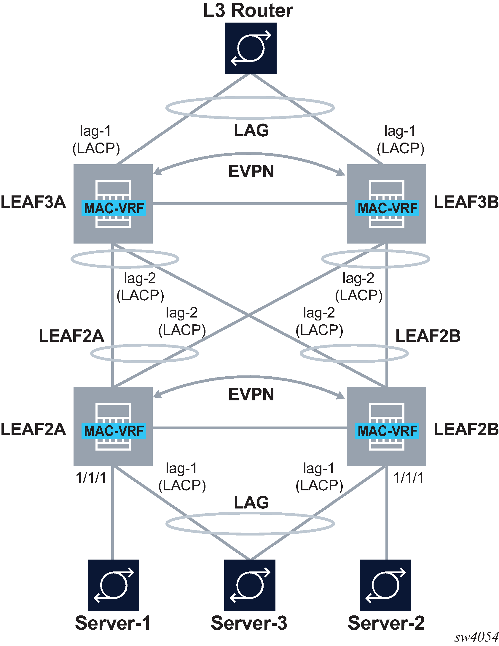
On the left side of EVPN multi-homing as standalone MC-LAG solution, EVPN Multi-homing is used as a standalone multi-homing solution for leaf nodes connected via bridged subinterfaces.
Leafs of a layer do not use VXLAN to get connected to the higher layer. In this case, EVPN sessions are configured locally within each multi-homing pair so that EVPN handles DF Election, split-horizon and synchronization of MAC and ARP entries. However, the leafs of different layers are not connected through any IP fabric, so no VXLAN or EVPN is needed end-to-end.
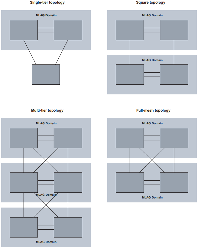
In this configuration, EVPN provides an alternative to MC-LAG solutions, being able to match all the topologies that other MC-LAG solutions support. These topologies include single-tier, multi-tier, square, or full-mesh/bow-tie topologies (see MLAG topologies below). EVPN multi-homing is supported in all of them as a replacement of MC-LAG.
Configuration for EVPN multi-homing as standalone MC-LAG
LEAF2A in EVPN multi-homing as standalone MC-LAG solution has the following configuration:
// lag1 connects LEAF2A to server-3
 and is associated to an all-active Ethernet Segment.
--{ candidate shared default }--[  ]--
A:LEAF2A# info interface lag*
    interface lag1 {
        admin-state enable
        vlan-tagging true
        subinterface 10 {
            type bridged
            vlan {
                encap {
                    single-tagged {
                        vlan-id 10
                    }
                }
            }
        }
        lag {
            lag-type static
 // lag-type could also be lacp, in which case the
 system-id/key must match on lag1 of LEAF2B
            member-speed 10G
        }
    }
// lag2 connects LEAF2A to LEAF3A and LEAF3B.
 This LAG is an access LAG (does not carry vxlan) associated to
 an all-active Ethernet Segment
    interface lag2 {
        admin-state enable
        vlan-tagging true
        subinterface 10 {
            type bridged
            vlan {
                encap {
                    single-tagged {
                        vlan-id 10
                    }
                }
            }
        }
        lag {
            lag-type static
 // lag-type could also be lacp, in which case the
 system-id/key must match on lag2 of LEAF2B
            member-speed 10G
        }
    }
// A vxlan-interface is created for the inter-chassis traffic
--{ candidate shared default }--[  ]-
A:LEAF2A# info tunnel-interface vxlan1 vxlan-interface 10
    tunnel-interface vxlan1 {
        vxlan-interface 10 {
            type bridged
            ingress {
                vni 10
            }
        }
    }
// the Ethernet Segments associated to lag1 and lag2
--{ candidate shared default }--[  ]--
A:LEAF2A# info system network-instance protocols evpn
    system {
        network-instance {
            protocols {
                evpn {
                    ethernet-segments {
                        bgp-instance 1 {
                            ethernet-segment ES-leaf1-leaf2.CE1 {
                                admin-state enable
                                esi 00:12:12:12:12:12:12:00:00:01
                                interface lag1
                            }
                            ethernet-segment ES-leaf1-leaf2.Spines {
                                admin-state enable
                                esi 00:12:12:12:12:12:12:00:00:02
                                interface lag2
                            }
                        }
                    }
                }
            }
        }
    }
// the mac-vrf uses lag sub-interfaces for the connectivity to rest of
 the leaf nodes and servers, and a vxlan-subinterface for the connectivity
 to LEAF2B
--{ candidate shared default }--[  ]--
A:LEAF2A# info network-instance Blue-MAC-VRF-10
    network-instance Blue-MAC-VRF-10 {
        type mac-vrf
        interface ethernet-1/1.10 {
            !!! this is connected to a single-homed access server-1
        }
        interface lag1.10 {
            !!! access lag - multi-homed to access server-3
        }
        interface lag2.10 {
            !!! multi-homed to spines
        }
        vxlan-interface vxlan1.10 {
            !!! vxlan-interface used for inter-chassis connectivity only
        }
        protocols {
            bgp-evpn {
                bgp-instance 1 {
                    admin-state enable
                    vxlan-interface vxlan1.10
                    evi 10
                }
            }
            bgp-vpn {
            }
        }
    }
LEAF2A in EVPN multi-homing as standalone MC-LAG solution has the following configuration:
// lag1 connects LEAF2B to server-3 and is associated to
 an all-active Ethernet Segment
--{ candidate shared default }--[  ]--
A:LEAF2B# info interface lag*
    interface lag1 {
        admin-state enable
        vlan-tagging true
        subinterface 10 {
            type bridged
            vlan {
                encap {
                    single-tagged {
                        vlan-id 10
                    }
                }
            }
        }
        lag {
            lag-type static
 // lag-type could also be lacp, in which case the
 system-id/key must match on lag1 of LEAF2A
            member-speed 10G
        }
    }
// lag2 connects LEAF2B to LEAF3A and LEAF3B.
 This LAG is an access LAG (does not carry vxlan) associated to
 an all-active Ethernet Segment
    interface lag2 {
        admin-state enable
        vlan-tagging true
        subinterface 10 {
            type bridged
            vlan {
                encap {
                    single-tagged {
                        vlan-id 10
                    }
                }
            }
        }
        lag {
            lag-type static
 // lag-type could also be lacp, in which case the
 system-id/key must match on lag2 of LEAF2B
            member-speed 10G
        }
    }
// A vxlan-interface is created for the inter-chassis traffic
--{ candidate shared default }--[  ]--
A:LEAF2B# info tunnel-interface vxlan1 vxlan-interface 10
    tunnel-interface vxlan1 {
        vxlan-interface 10 {
            type bridged
            ingress {
                vni 10
            }
        }
    }
// the Ethernet Segments associated to lag1 and lag2
--{ candidate shared default }--[  ]--
A:LEAF2B# info system network-instance protocols evpn
    system {
        network-instance {
            protocols {
                evpn {
                    ethernet-segments {
                        bgp-instance 1 {
                            ethernet-segment ES-leaf1-leaf2.CE1 {
                                admin-state enable
                                esi 00:12:12:12:12:12:12:00:00:01
                                interface lag1
                            }
                            ethernet-segment ES-leaf1-leaf2.Spines {
                                admin-state enable
                                esi 00:12:12:12:12:12:12:00:00:02
                                interface lag2
                            }
                        }
                    }
                }
            }
        }
    }
// the mac-vrf uses lag sub-interfaces for the connectivity to rest of the
 leaf nodes and servers, and a vxlan-subinterface for the connectivity
 to LEAF2B
--{ candidate shared default }--[  ]--
A:LEAF2B# info network-instance Blue-MAC-VRF-10
    network-instance Blue-MAC-VRF-10 {
        type mac-vrf
        interface ethernet-1/2.10 {
            !!! this is connected to a single-homed access server-2
        }
        interface lag1.10 {
            !!! access lag - multi-homed to access server-3
        }
        interface lag2.10 {
            !!! multi-homed to spines
        }
        vxlan-interface vxlan1.10 {
            !!! vxlan-interface used for inter-chassis connectivity only
        }
        protocols {
            bgp-evpn {
                bgp-instance 1 {
                    admin-state enable
                    vxlan-interface vxlan1.10
                    evi 10
                }
            }
            bgp-vpn {
            }
        }
    }