Multi-Chassis APS and Pseudowire Redundancy Interworking
This chapter describes multi-chassis APS and pseudowire redundancy interworking.
Topics in this chapter include:
Applicability
This chapter was initially written for SR OS Release 6.0.R2, but the CLI in the current edition is based on SR OS Release 19.10.R2.The configuration in this chapter includes the use of the ATM ports. See the Release Notes for information about support of ATM (and other) MDAs on various platforms as well as MC-APS restrictions.
Overview
MC-APS
MC-APS is an extension to the APS feature to provide not only link redundancy but also node level redundancy. It can protect against nodal failure by configuring the working circuit of an APS group on one node while configuring the protect circuit of the same APS group on a different node.
The two nodes connect to each other with an IP link that is used to establish a signaling path between them. The relevant APS groups in both the working and protection routers must have the same group ID and working circuit, and the protect circuit must have compatible configurations (such as the same speed, framing, and port type). Signaling is provided using the direct connection between the two service routers. A heartbeat protocol can be used to add robustness to the interaction between the two routers.
Signaling functionality includes support for:
APS group matching between service routers.
Verification that one side is configured as a working circuit and the other side is configured as the protect circuit. In case of a mismatch, a trap (incompatible-neighbor) is generated.
Change in working circuit status is sent from the working router to keep the protection router in sync.
Protection router, based on K1/K2 byte data, member circuit status, and external request, selects the active circuit and informs the working router to activate or de-activate the working circuit.
Pseudowire redundancy
Pseudowire (PW) redundancy provides the ability to protect a pseudowire with a pre-provisioned pseudowire and to switch traffic over to the secondary standby pseudowire in case of a SAP and/or network failure condition. Normally, pseudowires are redundant by the virtue of the SDP redundancy mechanism. For instance, if the SDP is an RSVP LSP and is protected by a secondary standby path and/or by Fast-Reroute paths, the pseudowire is also protected.
However, there are a few applications in which SDP redundancy does not protect the end-to-end pseudowire path when there are two different destination SR-series PE nodes for the same VLL service. The main use case is the provisioning of dual-homing of a CPE or access node to two SR-series PE nodes located in different POPs. The other use case is the provisioning of a pair of active and standby BRAS nodes, or active and standby links to the same BRAS node, to provide service resiliency to broadband service subscribers.
Example topology
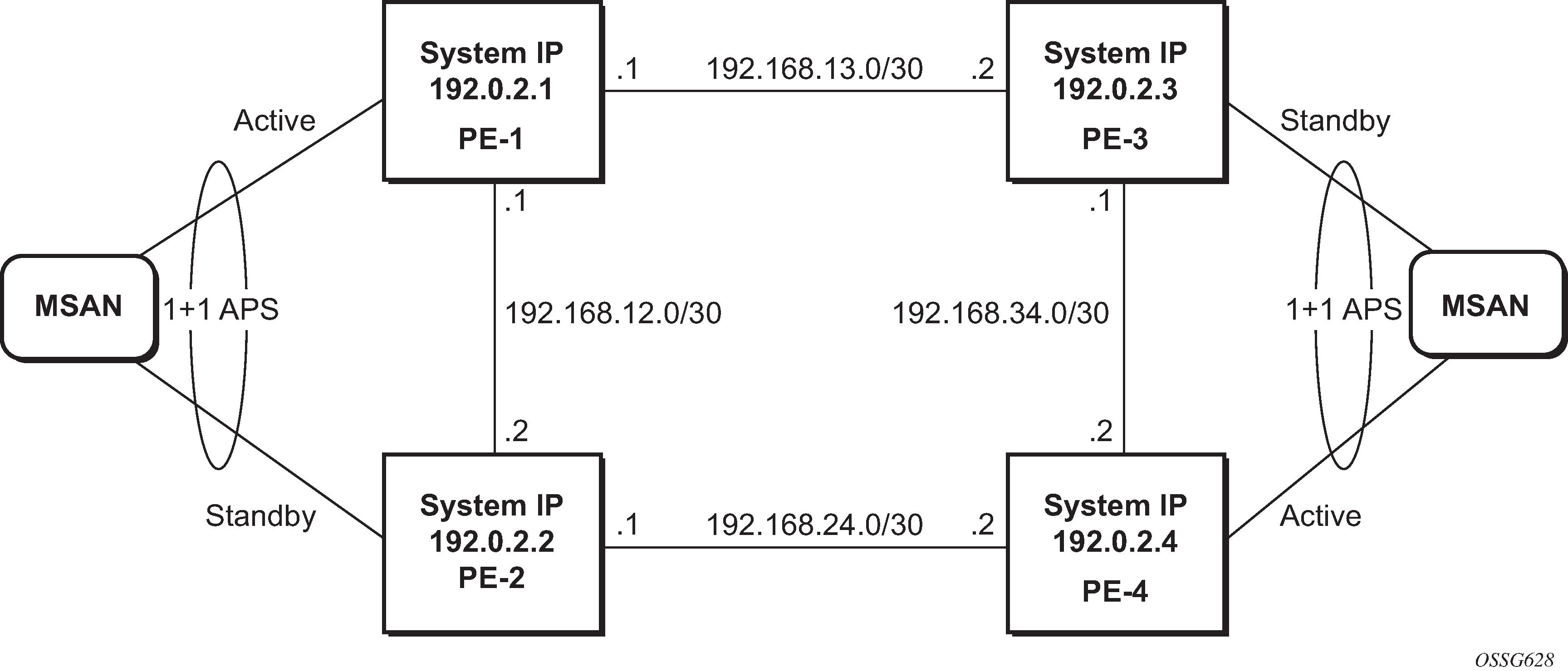
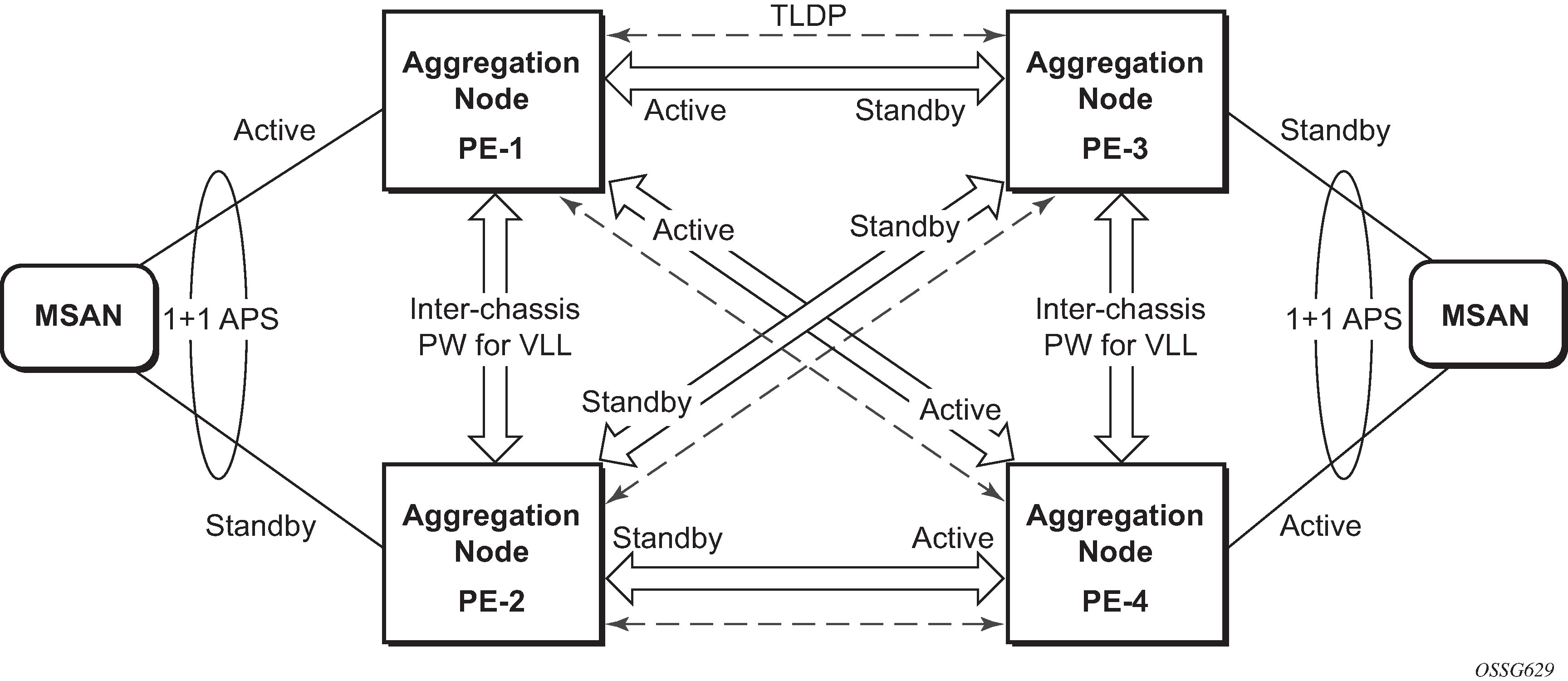
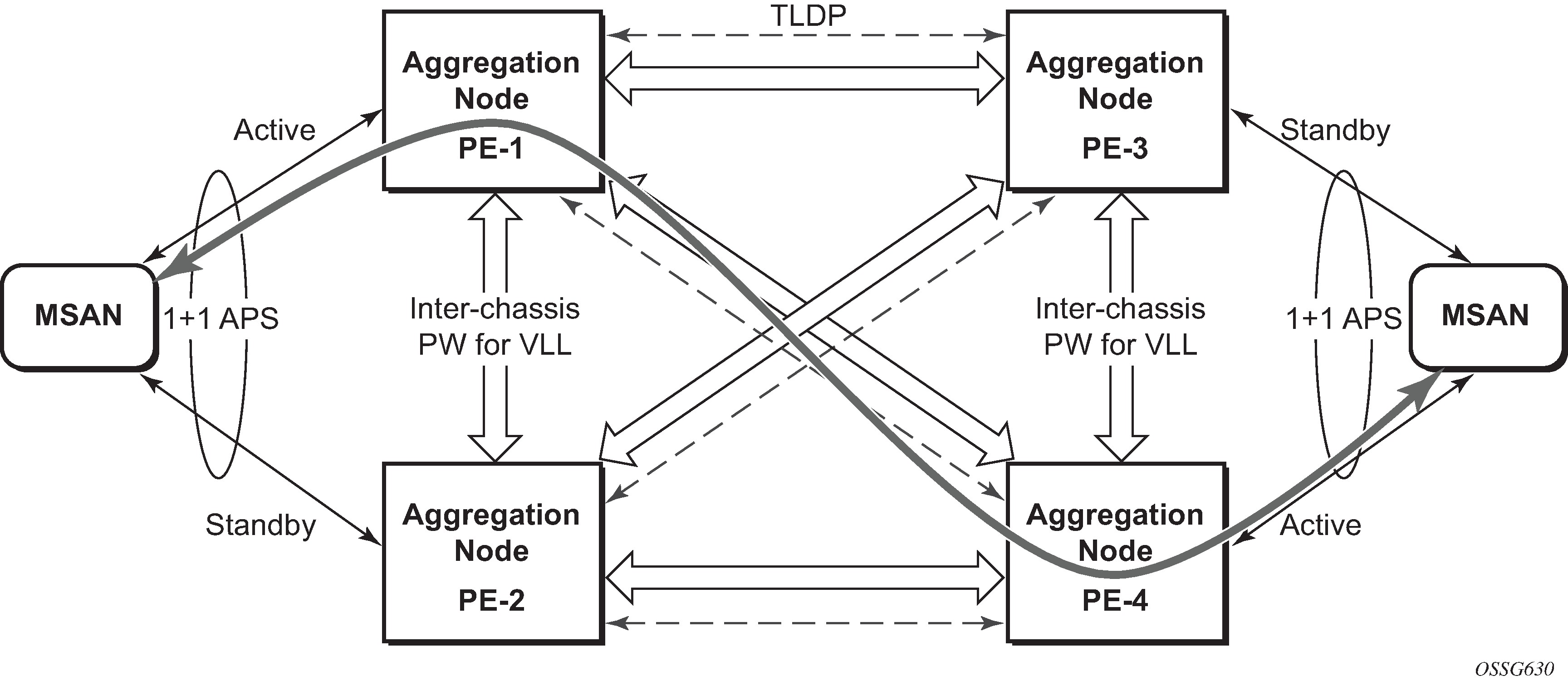
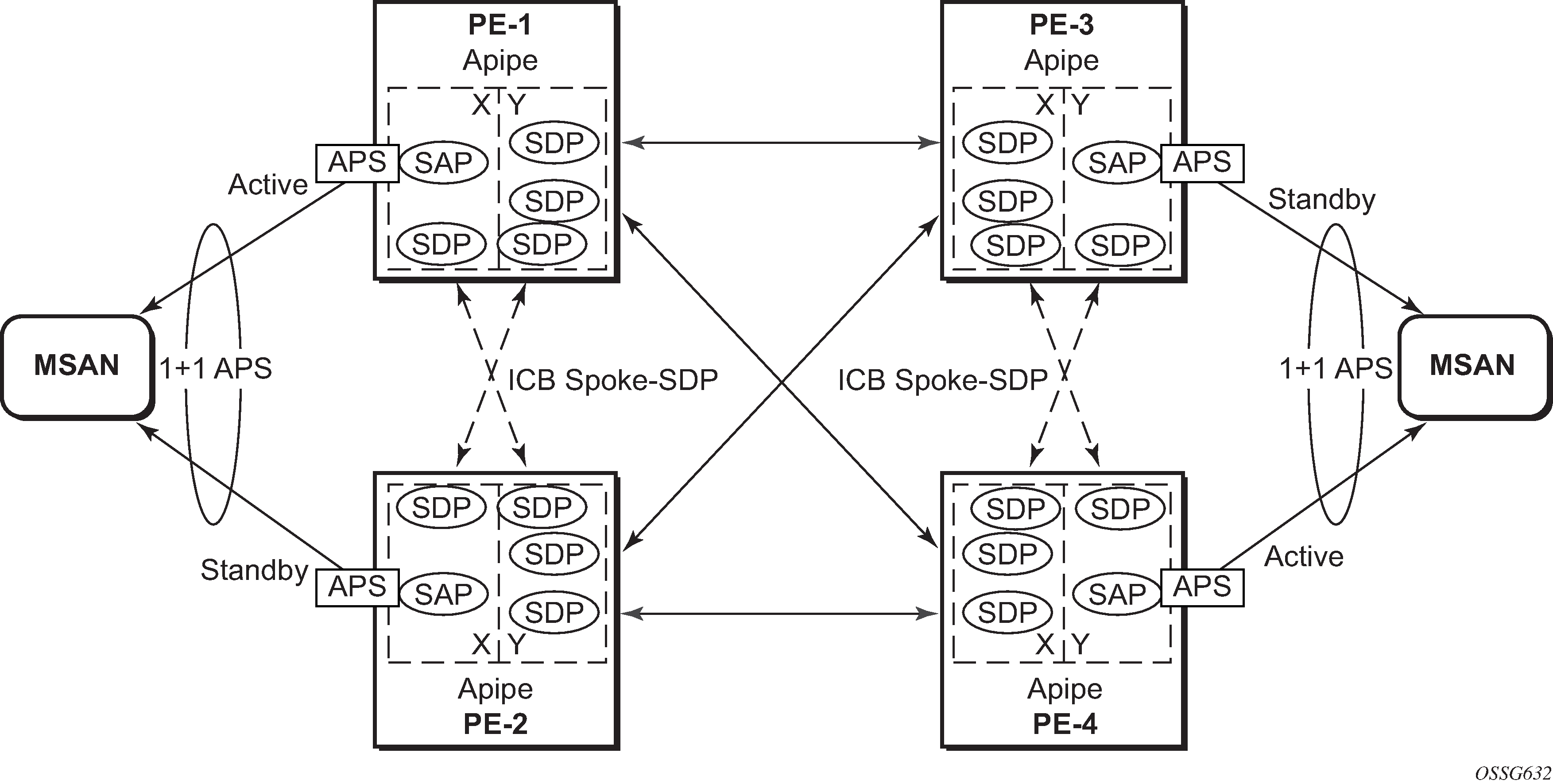
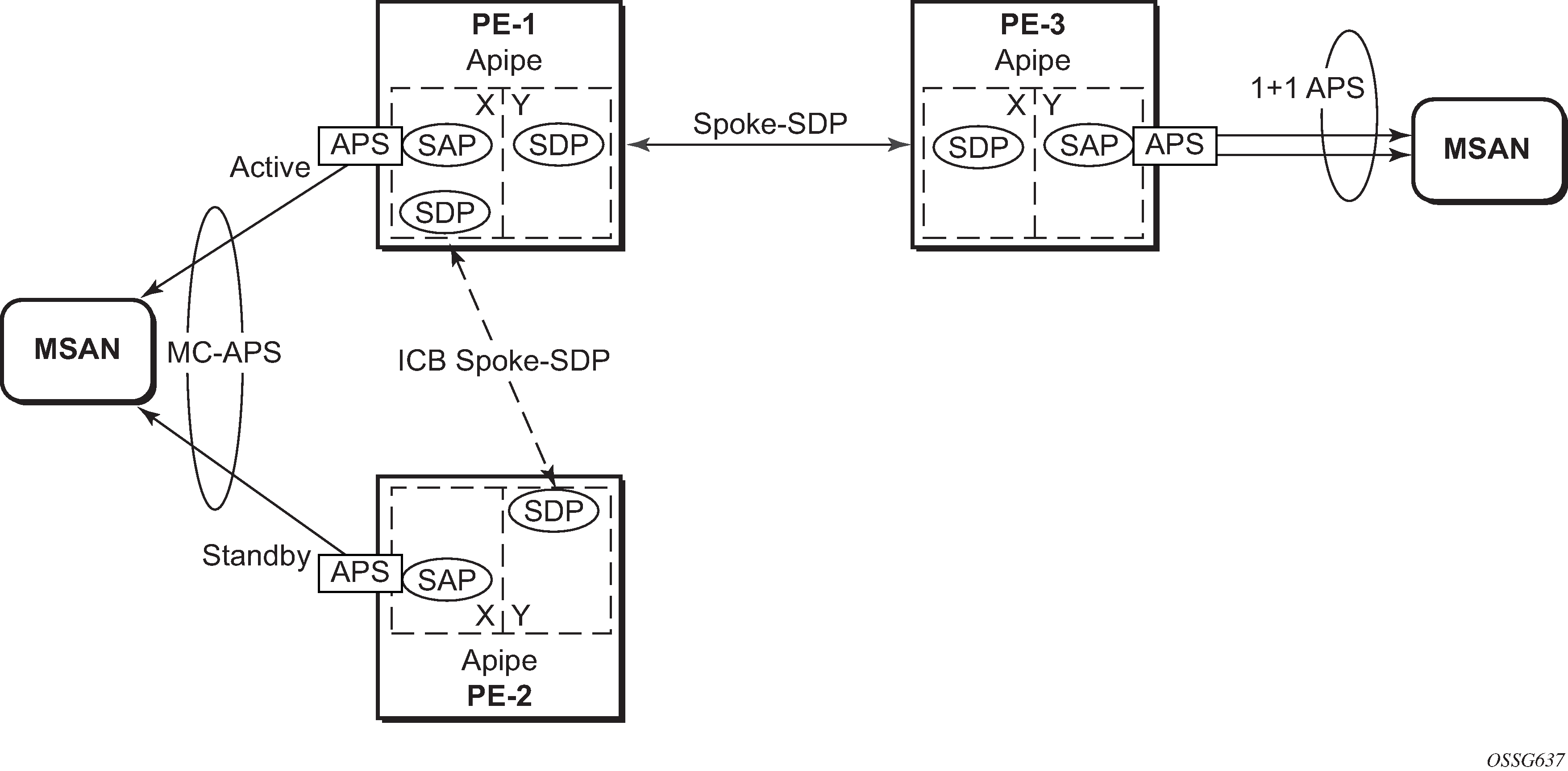
The setup in this section contains two access nodes and 4 PE nodes. The access nodes can be any ATM switches that support 1+1 bi-directional APS. MC-APS network topology shows the physical topology of the setup. Access node and network resilience (part 2) shows the use of both MC-APS in the access network and pseudowire redundancy in the core network to provide a resilient end-to-end VLL service.
Configuration
The following configuration should be completed on the PEs before configuring MC-APS:
Cards, MDAs and ports
Router interfaces
IGP configured and converged
MPLS
SDPs configured between all PE routers
For the IGP, OSPF or IS-IS can be used. MPLS or GRE can be used for the transport tunnels. Also, several protocols can be used for signaling MPLS labels. In this example, OSPF and LDP are used. The following commands can be used to check if OSPF has converged and to make sure the SDPs are up (for example, on PE-1):
*A:PE-1# show router route-table
===============================================================================
Route Table (Router: Base)
===============================================================================
Dest Prefix[Flags]                            Type    Proto     Age        Pref
      Next Hop[Interface Name]                                    Metric
-------------------------------------------------------------------------------
192.0.2.1/32                                  Local   Local     01h29m06s  0
       system                                                       0
192.0.2.2/32                                  Remote  OSPF      01h23m18s  10
       192.168.12.2                                                 100
192.0.2.3/32                                  Remote  OSPF      01h17m45s  10
       192.168.13.2                                                 100
192.0.2.4/32                                  Remote  OSPF      01h17m30s  10
       192.168.12.2                                                 200
192.168.12.0/30                               Local   Local     01h29m06s  0
       int-PE-1-PE-2                                                0
192.168.13.0/30                               Local   Local     01h29m06s  0
       int-PE-1-PE-3                                                0
192.168.24.0/30                               Remote  OSPF      01h23m18s  10
       192.168.12.2                                                 200
192.168.34.0/30                               Remote  OSPF      01h17m45s  10
       192.168.13.2                                                 200
-------------------------------------------------------------------------------
No. of Routes: 8
Flags: n = Number of times nexthop is repeated
       B = BGP backup route available
       L = LFA nexthop available
       S = Sticky ECMP requested
===============================================================================
*A:PE-1# show service sdp
============================================================================
Services: Service Destination Points
============================================================================
SdpId  AdmMTU  OprMTU  Far End          Adm  Opr         Del     LSP   Sig
----------------------------------------------------------------------------
12     0       1492    192.0.2.2        Up   Up          MPLS    L     TLDP
13     0       1492    192.0.2.3        Up   Up          MPLS    L     TLDP
14     0       1492    192.0.2.4        Up   Up          MPLS    L     TLDP
----------------------------------------------------------------------------
Number of SDPs : 3
----------------------------------------------------------------------------
Legend: R = RSVP, L = LDP, B = BGP, M = MPLS-TP, n/a = Not Applicable
        I = SR-ISIS, O = SR-OSPF, T = SR-TE, F = FPE
============================================================================
Step 1. APS configuration on MSANs
The access nodes can be any ATM switches that support 1+1 bi-directional APS. Here is an example on 7670RSP (Routing Switching Platform).
RSP> configure
RSP> port 1-6-1-1
RSP> options protection type 1+1
RSP> options protection switching bidirect
RSP> options protection
                                                                    (Standby)
#                  Type        Status           Name
1-6-1-1            STM1_IR8    OK
Protection Group Contains:
  Protection Port     : 1-6-1-1     (Standby)
  Working Port        : 1-5-1-1
Protection Type       : 1+1
Switching Type        : Non-Revertive
Switching Mode        : Bi-directional
Wait-To-Restore Timer :  5 minute(s)
Step 2. MC-APS configuration on PE-1 and PE-2
Assuming the link between MSAN and PE-1 is working circuit and the link between MSAN and PE-2 is protection circuit.
Configure APS on the PE-1 port. Specify the system IP address of neighbor node (PE-2) and working-circuit.
# on PE-1
configure
    port 1/2/1
        sonet-sdh
        exit
        no shutdown
    exit
    port aps-1
        aps
            neighbor 192.0.2.2
            working-circuit 1/2/1
        exit
        sonet-sdh
            path sts3
                encap-type atm
                crc 32
                atm
                exit
                no shutdown
            exit
        exit
        no shutdown
    exit
Configure APS on the PE-2 port. Specify the system IP address of neighbor node (PE-1) and protect-circuit instead of working-circuit.
# on PE-2
configure
    port 1/2/1
        sonet-sdh
        exit
        no shutdown
    exit
    port aps-1
        aps
            neighbor 192.0.2.1
            protect-circuit 1/2/1
        exit
        sonet-sdh
            path sts3
                encap-type atm
                crc 32
                atm
                exit
                no shutdown
            exit
        exit
        no shutdown
The following parameters can optionally be configured under APS.
advertise-interval — This command specifies the time interval, in 100s of milliseconds, between 'I am operational' messages sent by both protect and working circuits to their neighbor for multi-chassis APS.
hold-time — This command specifies how much time can pass, in 100s of milliseconds, without receiving an advertise packet from the neighbor before the multi-chassis signaling link is considered not operational.
revert-time — This command configures the revert-time timer to determine how long to wait before switching back to the working circuit after that circuit has been restored into service.
switching-mode — This command configures the switching mode for the APS port which can be bi-directional or uni-directional.
Step 3. Verify the APS status on PE-1.
*A:PE-1# show port aps-1

===============================================================================
SONET/SDH Interface
===============================================================================
Description        : APS Group
Interface          : aps-1                  Speed                : oc3
Admin Status       : up                     Oper Status          : up
Physical Link      : Yes                    Loopback Mode        : none
Single Fiber Mode  : No
Clock Source       : loop                   Framing              : sonet
Last State Change  : 01/10/2020 09:38:21    Port IfIndex         : 1358987264
Configured Address : 04:0f:ff:00:02:49
Hardware Address   : 04:0f:ff:00:02:49
Last Cleared Time  : N/A
J0 String          : 0x01                   Section Trace Mode   : byte
Rx S1 Byte         : 0x00 (stu)             Rx K1/K2 Byte        : 0x00/0x00
Tx S1 Byte         : 0x0f (dus)             Tx DUS/DNU           : Disabled
Rx J0 String (Hex) : 00 00 00 00 00 00 00 00 00 00 00 00 00 00 00 00
Cfg Alarm          : loc lrdi lb2er-sf slof slos
Alarm Status       :
BER SD Threshold   : 6                      BER SF Threshold     : 3
Hold time up       : 500 milliseconds       Reset On Path Down   : Disabled
Hold time down     : 200 milliseconds

===============================================================================
Port Statistics
===============================================================================
                                                   Input                 Output
-------------------------------------------------------------------------------
Packets                                                0                      0
Discards                                               0                      0
Unknown Proto Discards                                 0
===============================================================================
Step 4. Verify the MC-APS status and parameters on PE-1 and PE-2
Detailed parameters of the APS configuration on PE-1 can be verified, as follows. The admin/oper status of APS group 1 shows up/up. K1/K2 byte shows N/A as APS 1+1 exchanges that information through the protection circuit. The admin/oper status of the working circuit (the link between MSAN and PE-1) is up/up.
*A:PE-1# show aps detail

===============================================================================
APS Group: aps-1
===============================================================================
Description        : APS Group
Group Id           : 1                    Active Circuit       : 1/2/1
Admin Status       : Up                   Oper Status          : Up
Working Circuit    : 1/2/1                Protection Circuit   : N/A
Switching-mode     : Bi-directional       Switching-arch       : 1+1(sig-only)
Annex B            : No
Revertive-mode     : Non-revertive        Revert-time (min)    :
Rx K1/K2 byte      : N/A
Tx K1/K2 byte      : N/A
Current APS Status : OK
Multi-Chassis APS  : Yes
Neighbor           : 192.0.2.2
Control link state : Up
Advertise Interval : 1000 msec            Hold Time            : 3000 msec
Mode mismatch Cnt  : 0                    Channel mismatch Cnt : 0
PSB failure Cnt    : 0                    FEPL failure Cnt     : 0
-------------------------------------------------------------------------------
 APS Working Circuit - 1/2/1
-------------------------------------------------------------------------------
Admin Status       : Up                   Oper Status          : Up
Current APS Status : OK                   No. of Switchovers   : 0
Last Switchover    : None                 Switchover seconds   : 0
Signal Degrade Cnt : 0                    Signal Failure Cnt   : 0
Last Switch Cmd    : N/A                  Last Exercise Result : N/A
Tx L-AIS           : None
===============================================================================
Detailed parameters of the APS configuration on PE-2 can be verified, as follows. The admin/oper status of APS group 1 shows up/up. Both Rx and Tx of the K1/K2 byte are in the status of 0x00/0x05 (No-Req on Protect) as there is no failure or force-switchover request. The admin/oper status of the protection circuit (the link between MSAN and PE-2) is up/up.
*A:PE-2# show aps detail

===============================================================================
APS Group: aps-1
===============================================================================
Description        : APS Group
Group Id           : 1                    Active Circuit       : N/A
Admin Status       : Up                   Oper Status          : Up
Working Circuit    : N/A                  Protection Circuit   : 1/2/1
Switching-mode     : Bi-directional       Switching-arch       : 1+1(sig-only)
Annex B            : No
Revertive-mode     : Non-revertive        Revert-time (min)    :
Rx K1/K2 byte      : 0x00/0x05 (No-Req on Protect)
Tx K1/K2 byte      : 0x00/0x05 (No-Req on Protect)
Current APS Status : OK
Multi-Chassis APS  : Yes
Neighbor           : 192.0.2.1
Control link state : Up
Advertise Interval : 1000 msec            Hold Time            : 3000 msec
Mode mismatch Cnt  : 0                    Channel mismatch Cnt : 0
PSB failure Cnt    : 0                    FEPL failure Cnt     : 1
-------------------------------------------------------------------------------
 APS Working Circuit - Neighbor
-------------------------------------------------------------------------------
Admin Status       : N/A                  Oper Status          : N/A
Current APS Status : OK                   No. of Switchovers   : 0
Last Switchover    : None                 Switchover seconds   : 0
Signal Degrade Cnt : 0                    Signal Failure Cnt   : 1
Last Switch Cmd    : No Cmd               Last Exercise Result : Unknown
Tx L-AIS           : None
-------------------------------------------------------------------------------
 APS Protection Circuit - 1/2/1
-------------------------------------------------------------------------------
Admin Status       : Up                   Oper Status          : Up
Current APS Status : OK                   No. of Switchovers   : 0
Last Switchover    : None                 Switchover seconds   : 0
Signal Degrade Cnt : 0                    Signal Failure Cnt   : 0
Last Switch Cmd    : No Cmd               Last Exercise Result : Unknown
Tx L-AIS           : None
===============================================================================
Step 5. MC-APS configuration on PE-3 and PE-4
The MC-APS configuration on PE-3 and PE-4 is similar to the configuration on PE-1 and PE-2. Configure the working circuit on PE-4 and the protection circuit on PE-3.
Step 6. Pseudowire configuration
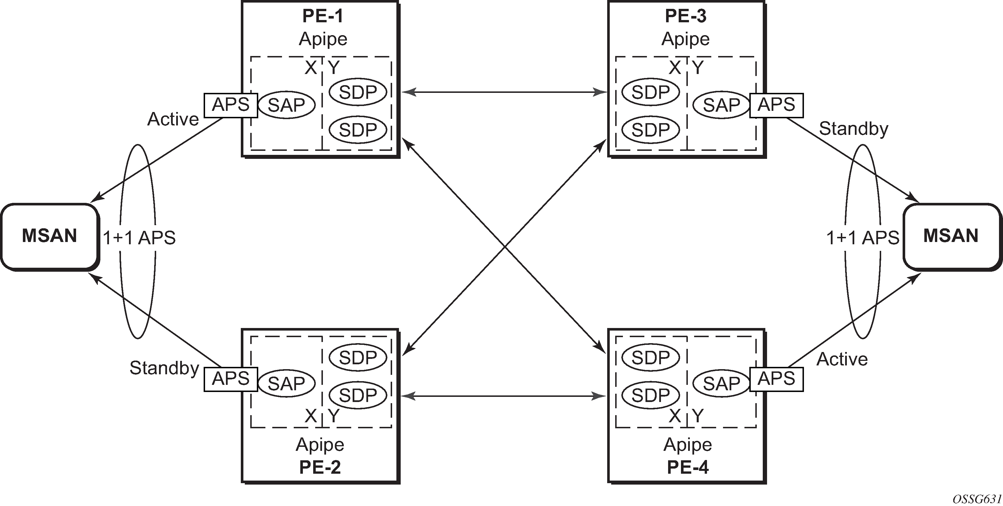
Configure an Apipe service on every PE and create endpoints X and Y. Associate the SAPs and spoke SDPs with the endpoints, as shown in Association of SAPs/SDPs and endpoints.
# on PE-1
configure
    service
        apipe 1 name name "Apipe 1" customer 1 create
            endpoint "X" create
            exit
            endpoint "Y" create
            exit
            service-mtu 1400
            sap aps-1:0/32 endpoint "X" create
            exit
            spoke-sdp 13:1 endpoint "Y" create
            exit
            spoke-sdp 14:1 endpoint "Y" create
            exit
            no shutdown
        exit
Syntax aps-1:0/32 specifies the APS group and VPI/VCI of the ATM circuit using the aps-id:vpi/vci format.
Likewise, an Apipe service, with endpoints, SAPs and spoke SDPs must be configured on the other PE routers.
Step 7. Pseudowire verification
The Apipe service is up in PE-1 (MC-APS working circuit), as follows:
*A:PE-1# show service service-using
===============================================================================
Services
===============================================================================
ServiceId    Type      Adm  Opr  CustomerId Service Name
-------------------------------------------------------------------------------
1            Apipe     Up   Up   1          1
---snip---
-------------------------------------------------------------------------------
Matching Services : 3
-------------------------------------------------------------------------------
===============================================================================
The Apipe service is down in PE-2 (MC-APS protect circuit), as follows:
*A:PE-2# show service service-using
===============================================================================
Services
===============================================================================
ServiceId    Type      Adm  Opr  CustomerId Service Name
-------------------------------------------------------------------------------
1            Apipe     Up   Down 1          1
---snip---
-------------------------------------------------------------------------------
Matching Services : 3
-------------------------------------------------------------------------------
===============================================================================
The Apipe service is down in PE-3 (MC-APS protect circuit), as follows:
*A:PE-3# show service service-using
===============================================================================
Services
===============================================================================
ServiceId    Type      Adm  Opr  CustomerId Service Name
-------------------------------------------------------------------------------
1            Apipe     Up   Down 1          1
---snip---
-------------------------------------------------------------------------------
Matching Services : 3
-------------------------------------------------------------------------------
===============================================================================
*A:PE-3#
The Apipe service is up in PE-4 (MC-APS working circuit), as follows:
*A:PE-4# show service service-using
===============================================================================
Services
===============================================================================
ServiceId    Type      Adm  Opr  CustomerId Service Name
-------------------------------------------------------------------------------
1            Apipe     Up   Up   1          1
---snip---
-------------------------------------------------------------------------------
Matching Services : 3
-------------------------------------------------------------------------------
===============================================================================
Note: After configuring ICB spoke-SDPs, the Apipe will be up on all PEs.
Step 8. Verify SDP status
The status of SDP 23:1 on PE-2 can be verified as follows.
Peer Pw Bits shows the status of the pseudowire on the peer node. In this example, both the local node (PE-2) as the remote node (PE-3) are sending the lacIngressFault, lacEgressFault and pwFwdingStandby flags. This is because the Apipe service on these nodes is down because the MC-APS is in protection status.
*A:PE-2# show service id 1 sdp 23:1 detail

===============================================================================
Service Destination Point (Sdp Id : 23:1) Details
===============================================================================
-------------------------------------------------------------------------------
 Sdp Id 23:1  -(192.0.2.3)
-------------------------------------------------------------------------------
Description     : (Not Specified)
SDP Id             : 23:1                     Type              : Spoke
Spoke Descr     : (Not Specified)
Split Horiz Grp    : (Not Specified)
VC Type            : AAL5SDU                  VC Tag            : 0
Admin Path MTU     : 0                        Oper Path MTU     : 1492
Delivery           : MPLS
Far End            : 192.0.2.3                Tunnel Far End    :
Oper Tunnel Far End: 192.0.2.3
LSP Types          : LDP

Admin State        : Up                       Oper State        : Up
MinReqd SdpOperMTU : 1404
Acct. Pol          : None                     Collect Stats     : Disabled
Ingress Label      : 524283                   Egress Label      : 524282
Ingr Mac Fltr-Id   : n/a                      Egr Mac Fltr-Id   : n/a
Ingr IP Fltr-Id    : n/a                      Egr IP Fltr-Id    : n/a
Admin ControlWord  : Preferred                Oper ControlWord  : True
Admin BW(Kbps)     : 0                        Oper BW(Kbps)     : 0
BFD Template       : None
BFD-Enabled        : no                       BFD-Encap         : ipv4
Last Status Change : 01/10/2020 09:46:58      Signaling         : TLDP
Last Mgmt Change   : 01/10/2020 09:46:52
Endpoint           : Y                        Precedence        : 4
PW Status Sig      : Enabled
Class Fwding State : Down
Flags              : None
Local Pw Bits      : lacIngressFault lacEgressFault pwFwdingStandby
Peer Pw Bits       : lacIngressFault lacEgressFault pwFwdingStandby
Peer Fault Ip      : None
Peer Vccv CV Bits  : lspPing bfdFaultDet
Peer Vccv CC Bits  : pwe3ControlWord mplsRouterAlertLabel

---snip---

===============================================================================
In case of failure, the access link can be protected by MC-APS. An MPLS network failure can be protected by pseudowire redundancy. Node failure can be protected by the combination of MC-APS and pseudowire redundancy.
Step 9. Inter-Chassis Backup (ICB) pseudowire configuration.
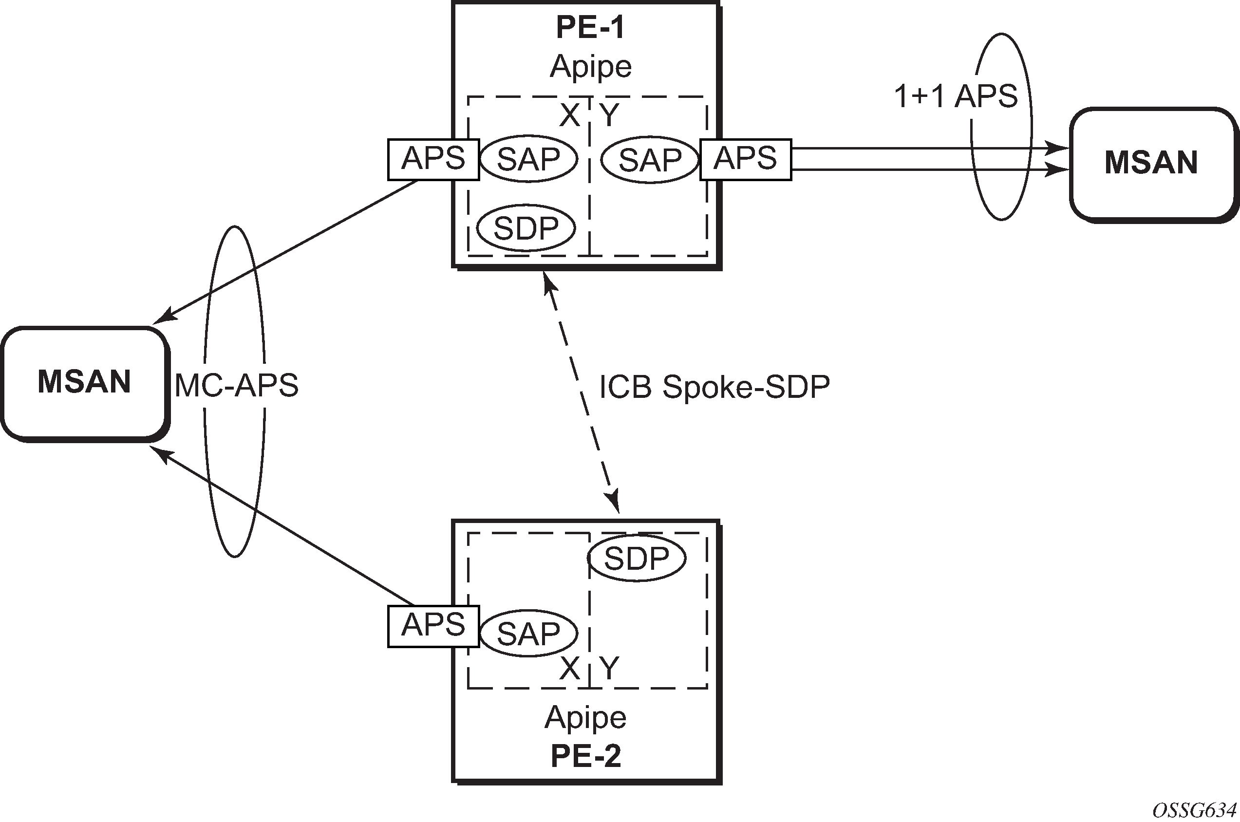
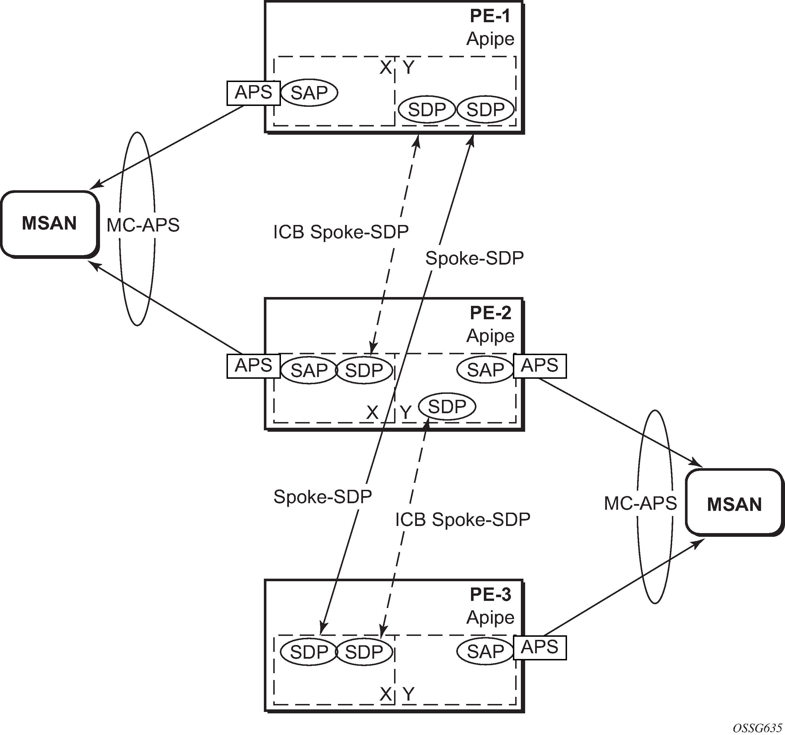
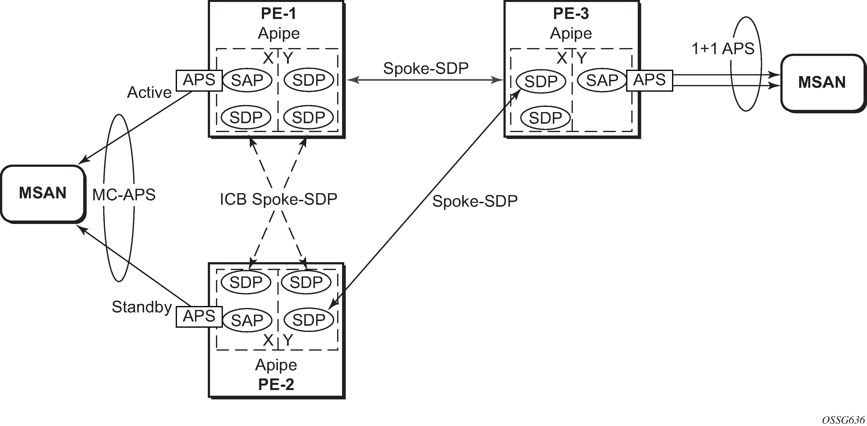
Configuring Inter-Chassis Backup (ICB) is optional. It can reduce traffic impact by forwarding traffic on ICB spoke SDPs during MC-APS switchover. The ICB spoke SDP cannot be added to the endpoint if the SAP is not part of an MC-APS (or MC-LAG) instance. Conversely, a SAP which is not part of a MC-APS (or MC-LAG) instance cannot be added to an endpoint which already has an ICB spoke SDP. Forwarding between ICBs is blocked on the same node. The user has to explicitly indicate the spoke SDP is actually an ICB at creation time. Figure 5 shows some setup examples where ICBs are required.
After configuring ICB spoke SDPs, the Apipe will be in admin/oper up/up status on all PE routers.
ICB SDPs are configured and associated to endpoints, as shown in ICB spoke SDPs and association with the endpoints.
Two ICB spoke SDPs must be configured in the Apipe service on each PE router, one in each endpoint. The same SDP IDs can be used for the ICBs since the far-end will be the same. However, the VC-id must be different. The ICB spoke SDPs must cross, meaning one end should be associated with endpoint X and the other end (on the other PE) should be associated with endpoint Y.
An ICB is always the last forwarding resort. Only one spoke SDP will be forwarding. If there is an ICB and an MC-APS SAP in an endpoint, the ICB will only forward if the SAP goes down. If an ICB resides in an endpoint together with other spoke SDPs the ICB will only forward if there is no other active spoke SDP.
The following shows the additional configuration for ICB on each PE:
# on PE-1
configure
    service
        apipe 1
            spoke-sdp 12:1 endpoint "X" icb create
            exit
            spoke-sdp 12:2 endpoint "Y" icb create
            exit
        exit
    exit
exit
# on PE-2
configure
    service
        apipe 1
            spoke-sdp 21:1 endpoint "Y" icb create
            exit
            spoke-sdp 21:2 endpoint "X" icb create
            exit
        exit
    exit
exit
# on PE-3
configure
    service
        apipe 1
            spoke-sdp 34:1 endpoint "X" icb create
            exit
            spoke-sdp 34:2 endpoint "Y" icb create
            exit
        exit
    exit
exit
# on PE-4
configure
    service
        apipe 1
            spoke-sdp 43:1 endpoint "Y" icb create
            exit
            spoke-sdp 43:2 endpoint "X" icb create
            exit
        exit
    exit
exit
Step 10. Verification of active objects for each endpoint
The following command shows which objects are configured for each endpoint and which is the active object at this moment:
*A:PE-1# show service id 1 endpoint

===============================================================================
Service 1 endpoints
===============================================================================
Endpoint name                : X
Description                  : (Not Specified)
Creation Origin              : manual
Revert time                  : 0
Act Hold Delay               : 0
Tx Active                    : aps-1:0/32
Tx Active Up Time            : 0d 00:38:31
Revert Time Count Down       : never
Tx Active Change Count       : 1
Last Tx Active Change        : 01/10/2020 09:46:45
-------------------------------------------------------------------------------
Members
-------------------------------------------------------------------------------
SAP      : aps-1:0/32                               Oper Status: Up
Spoke-sdp: 12:1 Prec:4 (icb)                        Oper Status: Up
===============================================================================
Endpoint name                : Y
Description                  : (Not Specified)
Creation Origin              : manual
Revert time                  : 0
Act Hold Delay               : 0
Tx Active (SDP)              : 14:1
Tx Active Up Time            : 0d 00:35:40
Revert Time Count Down       : never
Tx Active Change Count       : 2
Last Tx Active Change        : 01/10/2020 10:03:31
-------------------------------------------------------------------------------
Members
-------------------------------------------------------------------------------
Spoke-sdp: 12:2 Prec:4 (icb)                        Oper Status: Up
Spoke-sdp: 13:1 Prec:4                              Oper Status: Up
Spoke-sdp: 14:1 Prec:4                              Oper Status: Up
===============================================================================
===============================================================================
On PE-1, both the SAP and the spoke SDP 14:1 are active. The other objects do not forward traffic.
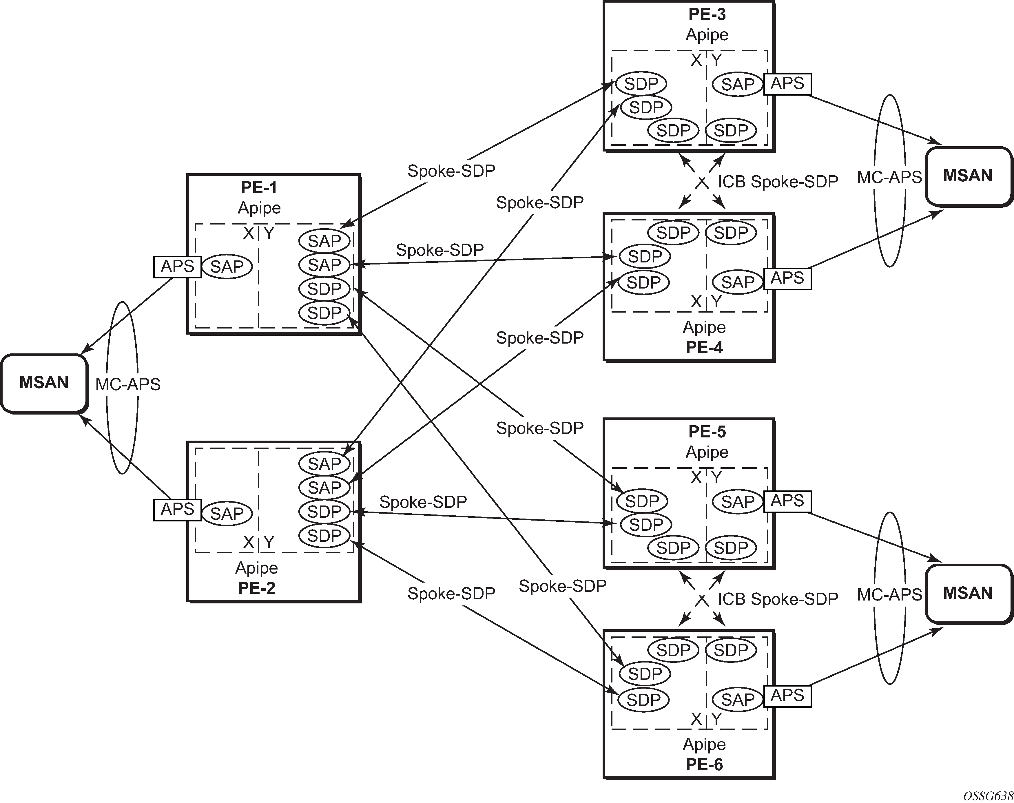
Step 11. Other types of setups
The following figures show other setups that combine MC-APS and pseudowire redundancy.
Forced switchover
MC-APS convergence can be forced with the tools perform aps command:
*A:PE-1# tools perform aps force
  - force <aps-id> {protect|working} [number <number>]

 <aps-id>             : aps-<group-id>
                          aps            - keyword
                          group-id       - [1..128]
 <protect|working>    : keyword
 <number>             : [1-2]
After the forced switchover, it is important to clear the forced switchover:
*A:PE-1# tools perform aps clear
  - clear <aps-id> {protect|working} [number <number>]

 <aps-id>             : aps-<group-id>
                          aps            - keyword
                          group-id       - [1..128]
 <protect|working>    : protect|working
 <number>             : [1-2]
Conclusion
In addition to Multi-Chassis LAG, Multi-Chassis APS provides a solution for both network redundancy and access node redundancy. It supports ATM VLL and Ethernet VLL with ATM SAP. Access links and PE nodes are protected by APS and the MPLS network is protected by pseudowire redundancy/FRR. With this feature, Nokia can provide resilient end-to-end solutions.