Port Cross-Connect (PXC)
This chapter provides information about Port Cross-Connect (PXC).
Topics in this chapter include:
Applicability
The chapter was initially written for SR OS Release 14.0.R5, but the CLI in the current edition is based on SR OS Release 21.2.R2.
Overview
The Port Cross-Connect (PXC) feature allows for a port, or number of ports, to be logically looped to themselves. The purpose of looping a port in this manner is to provide an "anchor point" function, such that traffic may ingress the node through any interface/port and be redirected to that anchor point.
When traffic is passed through the egress data path of the PXC, it can be used for additional packet processing that cannot be supported on the ingress data path, such as the removal of an encapsulation header. When traffic is looped back to the ingress data path of the PXC, it is processed as if it were the conventional service termination point. This essentially decouples the Input/Output (I/O) port through which packets ingress the node from the I/O port that implements the service termination. This decoupling removes the previous constraint for pseudowire-port (pw-port) whereby the I/O port through which packets ingress and egress the node was bound and could not be changed during, for example, a reconvergence event.
PXC provides two modes of operation: Distributed Versatile Service Module (DVSM) mode and Application Specific (AS) mode.
The DVSM mode provides functionality like that of the VSM2 card, enabling the user to create an internal loopback through the card. This allows for back-to-back configurations similar to a VLAN cross-connect.
The AS mode creates a Forwarding Path Extension (FPE) context through which the system can automatically create cross-connects to simplify user provisioning. Use-case examples for AS mode include PW port for business VPN services, VXLAN termination on a non-system interface, ESM over Pseudowire, and GRE tunnel termination.
This chapter describes the generic principles of PXC, combined with examples of both DVSM mode and AS mode.
Example topology
The topology shown in Example topology is used within this chapter to illustrate the use of PXC. PE-2, PE-3, and PE-5 form part of Autonomous System 64496 and run IS-IS level 2 together with LDP for the MPLS control plane. PE-2, PE-3, and PE-5 also peer in IBGP for the VPN-IPv4 address family. Test ports are connected to all PEs (in the case of PE-2 and PE-3, via CE routers) for the purpose of validating IP connectivity.
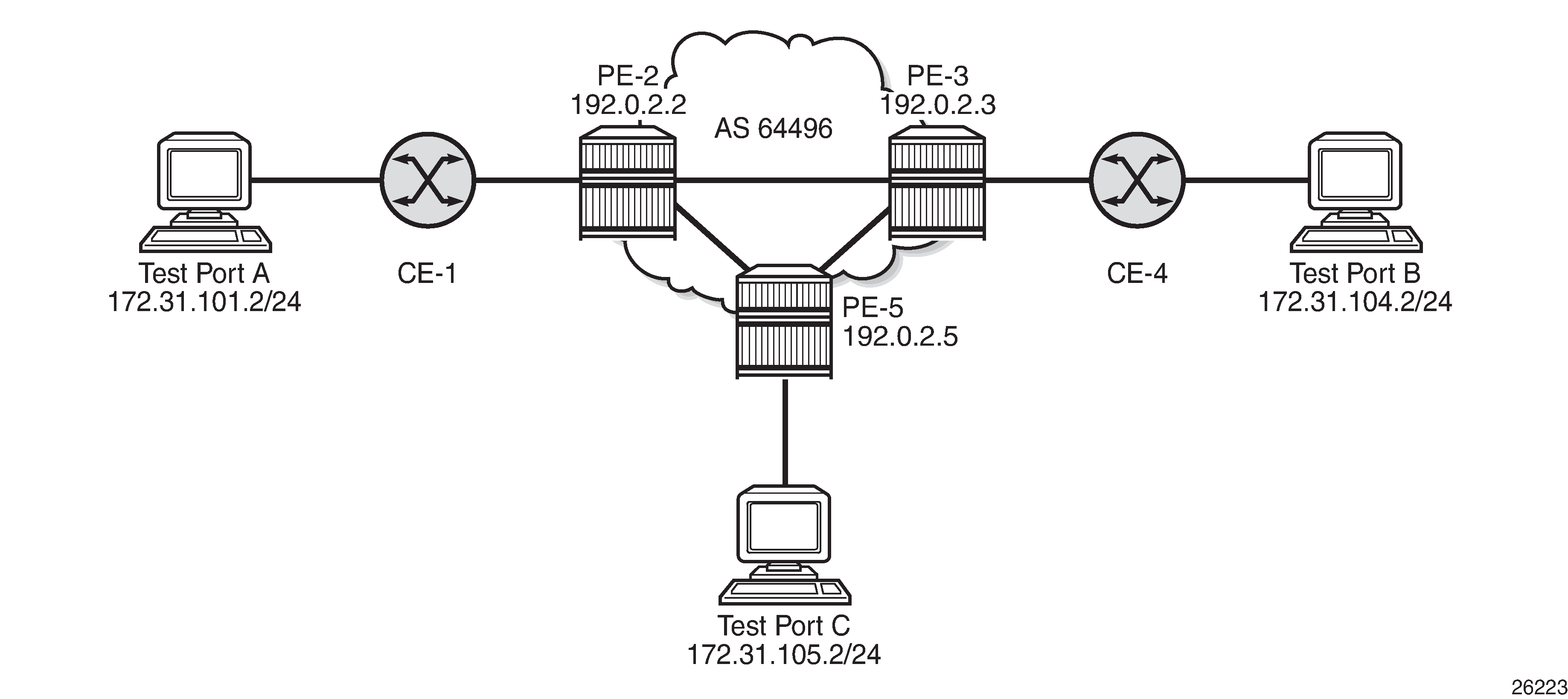
PE-5 will host the PXC.
Configuration
PXC configuration
A PXC can consist of a single non-redundant port, or for redundancy and increased capacity, can consist of multiple ports that form member links of a Link Aggregation Group (LAG). Both options are described here.
Non-redundant PXC
The non-redundant PXC is created within the port-xc context and can be numbered from 1 to 64. A port must be assigned to the PXC before it is put into a no shutdown state, and that port must be in a shutdown state when it is assigned. There is no requirement for any kind of optical transceiver to be inserted in the port assigned to the PXC; it is only a logical loopback. When the port is assigned to the PXC, it cannot be used for any other purpose besides a PXC-based service assignment (for example, a regular SAP could not be configured on this port).
# on PE-5:
configure
    port-xc
        pxc 1 create
            description "PXC non-redundant"
            port 1/2/1
            no shutdown
        exit
    exit
After the PXC has been put into a no shutdown state, two PXC sub-ports are automatically created by the system. The PXC sub-ports are identified by .a and .b suffixes of the parent PXC (in this example, pxc-1) and are created in hybrid mode with an MTU of 8700 bytes, both of which are non-configurable. The 8700-byte MTU represents the default port MTU (in this example, 8704 bytes) minus four bytes to allow for an internal VLAN tag that is used to identify each back-to-back sub-port. Finally, the encapsulation is set to dot1q, which is the default for hybrid ports. Q-in-Q encapsulation is also supported. It is also possible to configure dot1q encapsulation on one PXC sub-port and Q-in-Q encapsulation on the opposing PXC sub-port if, for example, there is a requirement to expose more VLAN tags on one side of the loop than the other side of the loop.
*A:PE-5# show port pxc 1
===============================================================================
Ports on Port Cross Connect 1
===============================================================================
Port          Admin Link Port    Cfg  Oper LAG/ Port Port Port   C/QS/S/XFP/
Id            State      State   MTU  MTU  Bndl Mode Encp Type   MDIMDX
-------------------------------------------------------------------------------
pxc-1.a       Down  Yes  Link Up 8700 8700    - hybr dotq xgige
pxc-1.b       Down  Yes  Link Up 8700 8700    - hybr dotq xgige
===============================================================================
After the PXC creation, the PXC sub-port CLI configuration is automatically generated and can be accessed in the same way as a conventional physical port, using the syntax "port pxc-n.l" where "n" represents the assigned PXC number and "l" represents the sub-port letter (a or b). As shown in the previous output, the sub-ports are in an admin down state following automatic creation and need to be manually put into a no shutdown state, as follows:
# on PE-5:
configure
    port pxc-1.a
        no shutdown
    exit
    port pxc-1.b
        no shutdown
    exit
The physical port assigned to the PXC must also now be put into a no shutdown state in order for the PXC to become operational:
# on PE-5:
configure
    port 1/2/1
        no shutdown
    exit
The command in the following output can then be used to verify the operational state of the PXC:
*A:PE-5# show port-xc pxc 1

===============================================================================
Port Cross-Connect Information
===============================================================================
PXC    Admin     Oper      Port        Description
Id     State     State     Id
-------------------------------------------------------------------------------
1      Up        Up        1/2/1       PXC non-redundant
===============================================================================
Similarly, the operational state of each of the sub-ports can be verified as follows. The physical link is indicated as being present even though there is no transceiver installed in this port.
*A:PE-5# show port pxc-1.a

===============================================================================
Ethernet Interface
===============================================================================
Description        : Port cross-connect
Interface          : pxc-1.a                    Oper Speed       : 10 Gbps
Link-level         : Ethernet                   Config Speed     : N/A
Admin State        : up                         Oper Duplex      : full
Oper State         : up
Config Duplex      : N/A
Physical Link      : Yes                        MTU              : 8700
Single Fiber Mode  : No                         Min Frame Length : 64 Bytes
IfIndex            : 1090523137                 Hold time up     : 0 seconds
Last State Change  : 05/18/2021 09:15:26        Hold time down   : 0 seconds
Last Cleared Time  : N/A
Phys State Chng Cnt: 0
---snip---
Non-redundant PXC shows a representation of the non-redundant PXC configuration. Both upstream and downstream traffic will pass twice through the FP data-path and port. For example, downstream traffic passes through the FP complex and PXC-1.b. The traffic is then looped back to PXC-1.a, and back into the FP complex. Similarly, upstream traffic passes through the FP complex to PXC-1.a. It is then looped back to PXC-1.b and back into the FP complex.
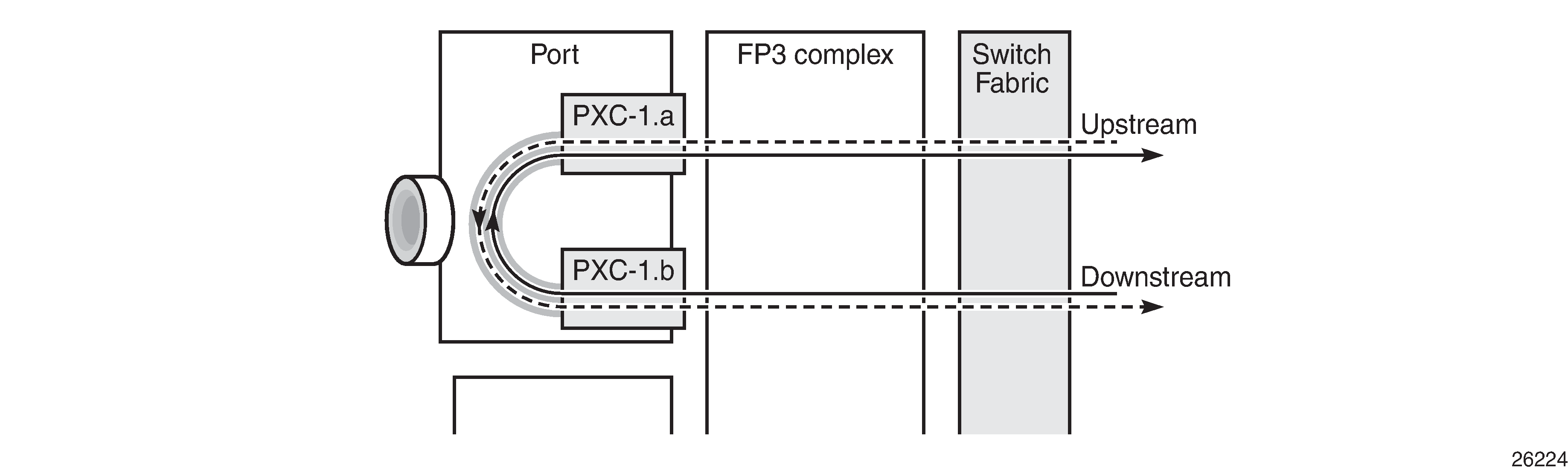
When using a PXC, the physical port effectively simulates two (sub-)ports, which creates two egress traffic paths: one upstream and one downstream. When the receive side of the PXC port receives those paths, it needs to distinguish between them, and this is where the internal additional VLAN tag is used.
The difference between this PXC configuration and a conventional port not looped or configured as PXC is as follows. With a conventional port, ingress traffic passes through the port and ingress data-path of the FP complex only once, and egress traffic passes through the egress data-path of the FP complex and port only once.
Redundant PXC
For a redundant PXC, the fundamental building blocks are identical to those of the non-redundant PXC, but there are a few additional configuration steps required to construct the LAGs to which the redundant PXC ports belong.
The redundant PXC example consists of two ports: 1/2/2 and 1/2/3 in the following output. In this case, the redundant PXC ports belong to the same IMM, but different IMMs can be used for increased redundancy. Two PXCs are created and each one is assigned one of the redundant PXC ports. Both PXCs are put into a no shutdown state.
# on PE-5:
configure
    port-xc
        pxc 2 create
            description "PXC redundant"
            port 1/2/2
            no shutdown
        exit
        pxc 3 create
            description "PXC redundant"
            port 1/2/3
            no shutdown
        exit
    exit
As with the non-redundant PXC, when the PXC has been put into a no shutdown state, two PXC sub-ports with .a and .b suffixes are automatically created by the system for each PXC port:
*A:PE-5# show port pxc [2..3]

===============================================================================
Ports on Port Cross Connect 2
===============================================================================
Port          Admin Link Port    Cfg  Oper LAG/ Port Port Port   C/QS/S/XFP/
Id            State      State   MTU  MTU  Bndl Mode Encp Type   MDIMDX
-------------------------------------------------------------------------------
pxc-2.a       Down  Yes  Link Up 8700 8700    - hybr dotq xgige
pxc-2.b       Down  Yes  Link Up 8700 8700    - hybr dotq xgige
===============================================================================

===============================================================================
Ports on Port Cross Connect 3
===============================================================================
Port          Admin Link Port    Cfg  Oper LAG/ Port Port Port   C/QS/S/XFP/
Id            State      State   MTU  MTU  Bndl Mode Encp Type   MDIMDX
-------------------------------------------------------------------------------
pxc-3.a       Down  Yes  Link Up 8700 8700    - hybr dotq xgige
pxc-3.b       Down  Yes  Link Up 8700 8700    - hybr dotq xgige
===============================================================================
The PXC sub-ports, together with the physical port, must then all be put into a no shutdown state:
# on PE-5:
configure
    port pxc-2.a
        no shutdown
    exit
    port pxc-2.b
        no shutdown
    exit
    port pxc-3.a
        no shutdown
    exit
    port pxc-3.b
        no shutdown
    exit
    port 1/2/2
        no shutdown
    exit
    port 1/2/3
        no shutdown
    exit
After the associated components have been put into a no shutdown state, the operational state of the PXCs can be verified:
*A:PE-5# show port-xc pxc [2..3]

===============================================================================
Port Cross-Connect Information
===============================================================================
PXC    Admin     Oper      Port        Description
Id     State     State     Id
-------------------------------------------------------------------------------
2      Up        Up        1/2/2       PXC redundant
===============================================================================

===============================================================================
Port Cross-Connect Information
===============================================================================
PXC    Admin     Oper      Port        Description
Id     State     State     Id
-------------------------------------------------------------------------------
3      Up        Up        1/2/3       PXC redundant
===============================================================================
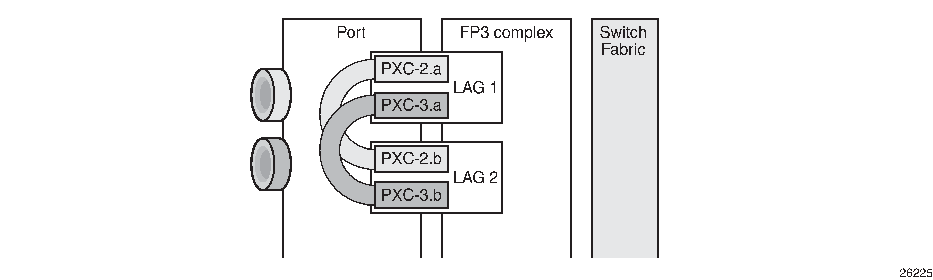
The PXC sub-ports are then associated with two LAGs to essentially form an internal back-to-back LAG. To do this, both sub-ports with the .a suffix belong to one LAG instance, and both sub-ports with the .b suffix belong to the other LAG instance. Like any other LAG member links, PXC sub-ports in a LAG must be configured with the same physical attributes, such as speed and duplex. Both LAG instances are configured with mode hybrid to match the mode of the physical ports. Setting the mode to hybrid automatically sets the encap-type to dot1q.
# on PE-5:
configure
    lag 1 name "lag-1"
        mode hybrid
        encap-type dot1q
        port pxc-2.a
        port pxc-3.a
        no shutdown
    exit
    lag 2 name "lag-2"
        mode hybrid
        encap-type dot1q
        port pxc-2.b
        port pxc-3.b
        no shutdown
    exit
PXC redundant mode with LAG shows a representation of the redundant PXC with LAG. Both upstream and downstream traffic will pass twice through the FP data-path and port.
When the LAGs are configured and the associated PXC sub-ports assigned as member links, the operational status can be verified. Note that at the LAG level, each of the configured LAG instances is not aware that it is internally connected to another LAG instance, even though the member sub-ports are logically looped. It would be possible, for example, to put LAG 1 into an admin shutdown state and not affect the operational state of LAG 2. LACP is not supported for PXC LAG; however, it is possible to run the 802.3ah Ethernet in the First Mile (EFM) at PXC sub-port level, if required.
*A:PE-5# show lag 1 detail

===============================================================================
LAG Details
===============================================================================
Description        : N/A
-------------------------------------------------------------------------------
Details
-------------------------------------------------------------------------------
Lag-id              : 1                     Mode                 : hybrid
Lag-name            : lag-1
Adm                 : up                    Opr                  : up
Thres. Last Cleared : 05/18/2021 08:35:32   Thres. Exceeded Cnt  : 0
Dynamic Cost        : false                 Encap Type           : dot1q
Configured Address  : 02:1f:ff:00:01:41     Lag-IfIndex          : 1342177281
Hardware Address    : 02:1f:ff:00:01:41     Adapt Qos (access)   : distribute
Hold-time Down      : 0.0 sec               Port Type            : standard
Per-Link-Hash       : disabled
Include-Egr-Hash-Cfg: disabled
Per FP Ing Queuing  : disabled              Per FP Egr Queuing   : disabled
Per FP SAP Instance : disabled
Access Bandwidth    : N/A                   Access Booking Factor: 100
Access Available BW : 0
Access Booked BW    : 0
LACP                : disabled
Standby Signaling   : lacp
Port hashing        : port-speed            Port weight speed    : 0 gbps
Ports Up            : 2
Weights Up          : 2                     Hash-Weights Up      : 20
Monitor oper group  : N/A
Adaptive loadbal.   : disabled              Tolerance            : N/A

-------------------------------------------------------------------------------
Port-id        Adm     Act/Stdby Opr     Primary   Sub-group     Forced  Prio
-------------------------------------------------------------------------------
pxc-2.a        up      active    up      yes       1             -       32768
pxc-3.a        up      active    up                1             -       32768
===============================================================================
DVSM mode
DVSM mode enables the creation of a back-to-back cross-connect. This back-to-back connection can be network-to-network, access-to-access, or a combination such as network-to-access. To provide an example of using DVSM mode, PE-3 in Example topology functions as a Layer 2 backhaul device, and PE-5 housing the PXC functions as the Layer 3 service edge. A pseudowire is extended from PE-3 to PE-5, where it is terminated in a VPRN, providing point-to-point connectivity between CE-4 and PE-5.
VLAN 100 is extended from CE-4 to PE-3, where it is indexed into an Epipe service. The SAP is service-delimiting; therefore, the VLAN is removed before frames are encapsulated into the pseudowire. The Epipe then has a single non-redundant spoke-SDP to PE-5 with VC-ID 11. The service configuration on PE-3 is as follows:
# on PE-3:
configure
    service
        sdp 35 mpls create
            far-end 192.0.2.5
            ldp
            keep-alive
                shutdown
            exit
            no shutdown
        exit
        epipe 11 name "Epipe 11" customer 1 create
            sap 1/1/3:100 create
                no shutdown
            exit
            spoke-sdp 35:11 create
                no shutdown
            exit
            no shutdown
        exit
At PE-5, the configuration of the corresponding end of the Epipe service is shown in the following output. This service consists of a single spoke-SDP toward PE-3 with VC-ID 11 to match the VC-ID advertised by PE-3, and a single SAP toward the PXC port. The syntax takes the form "pxc-n.l:vlan" where "n" is the PXC identifier, "l" is the sub-port letter (in this case .a), and "vlan" represents the VLAN identifier of the SAP.
As shown in the following output, the Epipe service uses PXC 1, which is the non-redundant PXC port. This is only an example; it could similarly use the redundant PXC port, in which case the SAP syntax would be the conventional LAG syntax (for example, lag-1:100, lag-2:100). Also note that although VLAN 100 is used both at PE-3's Epipe SAP and PE-5's Epipe PXC SAP, there is no correlation or dependence between the two. Both VLAN tags are service-delimiting and are subsequently stripped before the Ethernet frame is encapsulated into the pseudowire payload, so any valid VLAN value could be used at either point. The service configuration on PE-5 is as follows:
# on PE-5:
configure
    service
        sdp 53 mpls create
            far-end 192.0.2.3
            ldp
            keep-alive
                shutdown
            exit
            no shutdown
        exit
        epipe 11 name "Epipe 11" customer 1 create
            sap pxc-1.a:100 create
                no shutdown
            exit
            spoke-sdp 53:11 create
                no shutdown
            exit
            no shutdown
        exit
The VPRN configuration at the corresponding side of the PXC port is shown in the following output. The VPRN has two interfaces: the first is toward a directly connected test port used to verify IP connectivity, and the second ("to-CE-4") is toward CE-4 and has a SAP with a PXC syntax. The PXC syntax represents the same PXC and VLAN identifiers as the preceding Epipe configuration, but the PXC sub-port is .b, to represent the "other side" of the PXC logical loopback. Therefore, the VLAN values must match to create the back-to-back connection. Although not shown in the output (for brevity), a BGP session is configured between PE-5 and CE-4 for route exchange. The remainder of the VPRN parameters are generic and are not explained here.
# on PE-5:
configure
    service
        vprn 10 name "VPRN 10 using PXC DVSM" customer 1 create
            autonomous-system 64496
            interface "Test-Port-C" create
                address 172.31.105.1/24
                sap 1/1/3:100 create
                exit
            exit
            interface "to-CE-4" create
                address 192.168.45.2/30
                sap pxc-1.b:100 create
                exit
            exit
            bgp-ipvpn
                mpls
                    auto-bind-tunnel
                        resolution any
                    exit
                    route-distinguisher 64496:10
                    vrf-import "vrf10-import"
                    vrf-export "vrf10-export"
                    no shutdown
                exit
            exit
            bgp
                group "EBGP"
            ---snip---
            no shutdown
        exit
PXC port dimensioning
When the VPRN service at PE-5 is put into a no shutdown state, the EBGP session to CE-4 is established. The relevant routes are exchanged between CE-4 and PE-5 and traffic can be exchanged between test ports B (connected to CE-4) and C (connected to PE-5). Initially, traffic is sent from test port B toward port C at a rate of 100 packets/s. Traffic is intentionally sent in only one direction (in this example) to emphasize a point regarding PXC port dimensioning and capacity planning, as follows.
The PXC in use by the Epipe/VPRN service is PXC 1, which uses physical port 1/2/1. The following output shows a snapshot of a monitor command against the physical port. Although traffic is only being sent in a single direction (test port B behind CE-4 toward test port C connected to PE-5), the input/output rate of packets per second is the same at 100 packets/s. This is because the physical port consists of two PXC sub-ports that are looped. In this example, traffic is output from pxc-1.a when traffic is sent from the Epipe SAP into the PXC port, and traffic is input at pxc-1.b when traffic is received by the VPRN SAP from the PXC port. Because both upstream/ingress traffic and downstream/egress traffic will be seen as output packets using the available capacity of the physical port, this needs to be considered when capacity is being planned.
*A:PE-5# monitor port 1/2/1 rate interval 3

===============================================================================
Monitor statistics for Port 1/2/1
===============================================================================
                                                   Input                 Output
-------------------------------------------------------------------------------
---snip---
-------------------------------------------------------------------------------
At time t = 3 sec (Mode: Rate)
-------------------------------------------------------------------------------
Octets                                             51600                  51600
Packets                                              100                    100
Errors                                                 0                      0
Bits                                              412800                 412800
Utilization (% of port capacity)                   ~0.00                  ~0.00
QoS continuity
The application of ingress/egress SAP QoS policies is fundamentally the same for a PXC-based SAP as it is for a conventional SAP. However, there is a difference with regard to how ingress Forwarding Class (FC) mappings are maintained throughout the PXC in DVSM mode. On a conventional SAP, ingress packets are classified and mapped to an FC. That FC mapping is maintained (as part of the fabric header) when the packet transits through the system and is ultimately used to define the egress queue and egress marking, such as MPLS EXP bits or dot1p bits.
However, the PXC sub-ports are subtly different. Consider SAP ingress traffic entering the VPRN at PE-5 from the locally connected test port C destined toward test port B at CE-4. At the ingress to PE-5, this traffic is mapped to FC Expedited Forwarding (EF) and forwarded into the PXC port through SAP pxc-1.b:100. When the traffic is forwarded out of the (PXC) SAP, the fabric header is removed as if it were a conventional SAP, and therefore, the information conveying the FC mapping is lost. When the traffic arrives at the opposing PXC sub-port SAP (in this case, pxc-1.a:100), a further FC classification is undertaken, and without some non-default configuration, traffic will be classified as FC Best Effort (BE). Therefore, it is a requirement to use non-default ingress/egress QoS policies through the PXC port in order to maintain FC continuity. A relatively simple way to do to this is through the use of dot1p markings.
To illustrate how this FC continuity is achieved, and in general how QoS is applied to PXC ports, an example of the relevant policies applied to PE-5's egress traffic toward CE-4 is used.
The first of the following outputs provides an example of the SAP-egress QoS policy applied at the VPRN PXC SAP (pxc-1.b:100). There are three classes in use: BE, Assured-Forwarding (AF), and EF. These FCs are remapped to queues 1, 2, and 3, respectively, and each queue is mapped to a parent H-QoS scheduler. Because the FCs must be maintained through the PXC loop, dot1p markings are used to distinguish between them. FC EF uses dot1p 5, FC AF uses dot1p 3, and FC BE uses dot1p 1. The SAP egress QoS policy is configured on PE-5 as follows:
# on PE-5:
configure
    qos
        sap-egress 2 name "SAP egress 2" create
            queue 1 create
                parent "aggregate-rate" level 2 weight 10
            exit
            queue 2 best-effort create
                parent "aggregate-rate" level 2 weight 40 cir-level 2
                rate 5000 cir max
            exit
            queue 3 expedite create
                parent "aggregate-rate" cir-level 3
                rate 2000 cir 2000
            exit
            fc af create
                queue 2
                dot1p 3
            exit
            fc be create
                queue 1
                dot1p 1
            exit
            fc ef create
                queue 3
                dot1p 5
            exit
        exit
The configuration of the Tier 1 scheduler "aggregate-rate" referenced by the child queues in the preceding SAP-egress QoS policy is shown in the following output. The scheduler in turn references a port-scheduler-policy using the command port-parent. Parenting to a port-scheduler is optional, but allows for inclusion of Preamble and Inter-Frame Gap (IFG) in the QoS scheduling algorithm, which is otherwise not included by a conventional H-QoS scheduler. The port-scheduler-policy "port-scheduler" is not referenced directly by the Tier 1 scheduler, but rather the port-scheduler is inherited by any child queues on the port to which the port-scheduler is applied. In this case, the port-scheduler-policy "port-scheduler" is applied to the PXC sub-port pxc-1.b as follows:
# on PE-5:
configure
    qos
        port-scheduler-policy "port-scheduler" create
        exit
        scheduler-policy "egress-hqos-scheduler" create
            tier 1
                scheduler "aggregate-rate" create
                    port-parent
                    rate 1
                exit
            exit
        exit
    exit
    port pxc-1.b
        ethernet
            egress-scheduler-policy "port-scheduler"
        exit
        no shutdown
    exit
Finally, the SAP-egress QoS policy is applied to the PXC sub-port SAP within the vprn interface context. The H-QoS scheduler is also attached and an override of the rate configured. In summary, the SAP-egress QoS policy configuration looks exactly like that used on a conventional SAP, other than the dot1p markings used for FC continuity, which may not always be used or required.
# on PE-5:
configure
    service
        vprn 10 name "VPRN 10 using PXC DVSM" customer 1 create
            interface "to-CE-4" create
                address 192.168.45.2/30
                sap pxc-1.b:100 create
                    egress
                        scheduler-policy "egress-hqos-scheduler"
                        scheduler-override
                            scheduler "aggregate-rate" create
                                rate 20000
                            exit
                        exit
                        qos 2
                    exit
                exit
            exit
On the opposing side of the PXC loop, the dot1p markings imposed by the VPRN SAP egress are used to reclassify traffic back to its original FC mapping. The following output shows the SAP-ingress QoS policy applied at the Epipe PXC sub-port SAP (pxc-1.a:100). As shown in this output, dot1p 5 is mapped to FC EF, dot1p 3 is mapped to FC AF, and dot1p 1 is mapped to FC BE, thereby retaining the FC mappings through the PXC port.
# on PE-5:
configure
    qos
        sap-ingress 11 name "SAP ingress 11" create
            queue 1 create
            exit
            queue 2 best-effort create
                rate max cir max
            exit
            queue 3 expedite create
                rate max cir max
            exit
            fc "af" create
                queue 2
            exit
            fc "be" create
                queue 1
            exit
            fc "ef" create
                queue 3
            exit
            dot1p 1 fc "be"
            dot1p 3 fc "af"
            dot1p 5 fc "ef"
        exit
# on PE-5:
configure
    service
        epipe 11 name "Epipe 11" customer 1 create
            sap pxc-1.a:100 create
                ingress
                    qos 11
                exit
                no shutdown
            exit
        exit
The preceding configuration shows the required QoS policies for downstream traffic (VPRN egress to Epipe ingress). Corresponding QoS policies must also be configured for upstream traffic (Epipe egress to VPRN ingress). For brevity, they are not shown here.
AS mode
AS mode creates an FPE context that is used to provide information to the system about which PXC ports or LAGs are paired, so that the configuration process can be simplified by automatic provisioning of cross-connects. To illustrate the use of AS mode, the redundant PXC (formed of LAG 1 and 2) configured earlier in this chapter is used. However, redundancy is not a requirement. Non-redundant PXC ports can also be used with AS mode.
For AS mode, a similar setup to the DVSM example is used, with Epipe termination into a VPRN. This provides a generic view of the applicability of AS mode, but also allows a direct comparison between the DVSM and AS mode approaches. Again, PE-3 in Example topology functions as a Layer 2 backhaul device and PE-5 hosts the PXC functions as the Layer 3 service edge. A pseudowire is extended from PE-3 to PE-5 where it will be terminated in a VPRN, providing point-to-point connectivity between CE-4 and PE-5.
The following output illustrates the configuration of the Epipe service at PE-3. CE-4 uses Q-in-Q encapsulation on the PE-CE link to PE-3 with SVLAN tag 100 and CVLAN tag 1024. At PE-3, it is indexed into an Epipe service using a q.* SAP to make the CVLAN tag transparent (part of the payload). As the spoke-SDP toward PE-5 is also configured with force-vlan-vc-forwarding, both SVLAN and CVLAN tags will be encapsulated in the pseudowire payload.
# on PE-3:
configure
    service
        epipe 13 name "Epipe 13" customer 1 create
            sap 1/1/3:100.* create
                no shutdown
            exit
            spoke-sdp 35:13 create
                force-vlan-vc-forwarding
                no shutdown
            exit
            no shutdown
        exit
As in the previous configuration example, LAG 1 and LAG 2 are used for PXC redundancy. LAG 1 has the PXC sub-ports pxc-2.a and pxc-3.a as member links, while LAG 2 has the PXC sub-ports pxc-2.b and pxc-3.b as member links. For AS mode, the next requirement is to configure the FPE construct and assign the paired LAG instances to that FPE. When entering the fwd-path-ext context, the sdp-id-range must be configured before any fpe instances can be created. The sdp-id-range allocates a block of SDP identifiers to be used for the automatic cross-connects between service applications and the FPE. Up to 128 SDP identifiers can be allocated in the range 1 to 17407.
After the sdp-id-range is configured, the fpe instance is created and the user enters the fpe context. The path command is used to assign redundant or non-redundant PXC objects to the FPE. In the case of a non-redundant FPE, the path command would refer to a pxc instance. In the case of a redundant FPE, the path syntax requires that each of the paired LAG instances is assigned to cross-connect "a" or cross-connect "b". Each FPE has two fundamental components, known as the transit side and the terminating side. The transit side is the side where additional traffic preprocessing is carried out, such as header removal or manipulation. It can be considered as the side closest to the network. The terminating side is the side where the preprocessed traffic is terminated in a service. When an FPE is used, the system automatically assigns cross-connect "a" to the transit side, and cross-connect "b" to the terminating side. In the following example, the command path xc-a lag-1 xc-b lag-2 assigns LAG 1 to cross-connect "a" and LAG 2 to cross-connect "b". This means that LAG 1 is the transit side while LAG 2 is the terminating side.
The application of the FPE also needs to be configured. In this example, pw-port is selected to allow for support of pseudowire-SAP (including Enhanced Subscriber Management (ESM) over pseudowire). The other available options (for example, vxlan-termination) are beyond the scope of this chapter.
# on PE-5:
configure
    fwd-path-ext
        sdp-id-range from 17280 to 17407
        fpe 1 create
            path xc-a lag-1 xc-b lag-2
            pw-port
        exit
    exit
After the LAG instance is assigned to the FPE, it can no longer be used for other general purposes, such as IP interfaces and/or SAPs. Any attempt to do so is blocked in CLI. The operational state of the FPE can be verified as shown in the following output. It is also useful to be able to identify the services and pw-ports that are mapped to an FPE. This can be obtained using the show fwd-path-ext fpe <number> associations command.
*A:PE-5# show fwd-path-ext fpe 1

===============================================================================
FPE Id: 1
===============================================================================
Description        : (Not Specified)
Path               : lag 1, lag 2
Pw Port            : Enabled                           Oper     : up
Sub Mgmt Extension : Disabled                          Oper     : N/A
Vxlan Termination  : Disabled                          Oper     : down
Segment-Routing V6 : Disabled
===============================================================================
The next step is to configure a pseudowire-port (pw-port) that will be used for terminating services. The creation of the pw-port creates a new context in which the only required configuration is to define the encapsulation type as dot1q or qinq. In this instance, the pw-port will support encap-type qinq.
# on PE-5:
configure
    pw-port 1 create
        encap-type qinq
    exit
The operational state of the pw-port is captured as a reference at this point, so that a comparison can be made later in the configuration process.
*A:PE-5# show pw-port 1

===================================================================
PW Port Information
===================================================================
PW Port   Encap          SDP:VC-Id               IfIndex
-------------------------------------------------------------------
1         qinq           N/A                     1526726657
===================================================================
At PE-5, the requirement now is to link the spoke-SDP from PE-3 to the configured pw-port (pw-port 1) via the FPE. To do this, an Epipe service must be used that is configured for multi-segment pseudowire working, using the creation-time attribute vc-switching. The Epipe service consists of a single spoke-SDP toward PE-3 with a VC-ID matching that signaled by PE-3 (VC-ID 13). The second endpoint within the Epipe service uses the command pw-port 1 fpe 1 to reference the previously configured pw-port and FPE objects. This command essentially creates an internal cross-connect between the Epipe service and the pw-port via the configured FPE object.
# on PE-5:
configure
    service
        epipe 13 name "Epipe 13" customer 1 vc-switching create
            pw-port 1 fpe 1 create
                no shutdown
            exit
            spoke-sdp 53:13 create
                no shutdown
            exit
            no shutdown
        exit
The following output shows the SDPs belonging to the preceding vc-switched Epipe service configured. The first SDP with identifier 53:13 is the pseudowire toward PE-3 with VC-ID 13. The second SDP has identifier 17280:1 allocated from the preconfigured sdp-id-range, and has a type of Fpe. In the configuration of fpe 1, the path command assigned LAG 1 to cross-connect "a" (xc-a) and LAG 2 to cross-connect "b" (xc-b). Also, cross-connect "b" is always automatically assigned to the terminate side of the FPE. Therefore, the Far End address is shown as fpe_1.b, in order to terminate the service.
*A:PE-5# show service id 13 sdp

===============================================================================
Services: Service Destination Points
===============================================================================
SdpId            Type     Far End addr    Adm     Opr       I.Lbl     E.Lbl
-------------------------------------------------------------------------------
53:13            Spok     192.0.2.3       Up      Up        524280    524283
17280:1          Fpe      fpe_1.b         Up      Up        524282    524281
-------------------------------------------------------------------------------
Number of SDPs : 2
-------------------------------------------------------------------------------
===============================================================================
With the vc-switching Epipe service configured and operational, the state of the pw-port can again be shown in the following output. Before the configuration of the vc-switching Epipe, the pw-port had no SDP identifier or VC-ID. Now both entries exist; automatically created by the system when pw-port 1 fpe 1 was configured as an endpoint within the vc-switching Epipe. The SDP identifier of 17281 is allocated from the preconfigured sdp-id-range.
*A:PE-5# show pw-port 1

===================================================================
PW Port Information
===================================================================
PW Port   Encap          SDP:VC-Id               IfIndex
---------------------------------------------------------------------
1         qinq           17281:100001            1526726657
===================================================================
The output for SDP 17281 shows that the Far End is fpe_1.a (transit), the Delivery (Del) is MPLS, the LSP type is FPE (F), and that no signaling (Sig) is used for this internal SDP, as follows:
*A:PE-5# show service sdp 17281

============================================================================
Service Destination Point (Sdp Id : 17281)
============================================================================
SdpId  AdmMTU  OprMTU  Far End          Adm  Opr         Del     LSP   Sig
----------------------------------------------------------------------------
17281  0       8678    fpe_1.a          Up   Up          MPLS    F     None
============================================================================
In SR OS, the combination of SDP ID and VC-ID is always associated with a service. When using AS mode, the system automatically creates an internal VPLS service with ID 2147383649 and a name of _tmns_InternalVplsService. This VPLS includes all internal SDPs dynamically created for binding pw-ports to the transit side of the corresponding FPE. The VPLS is an internal construct that does not affect forwarding.
AS mode with redundant FPE shows the components of the FPE from vc-switching Epipe to pw-port.
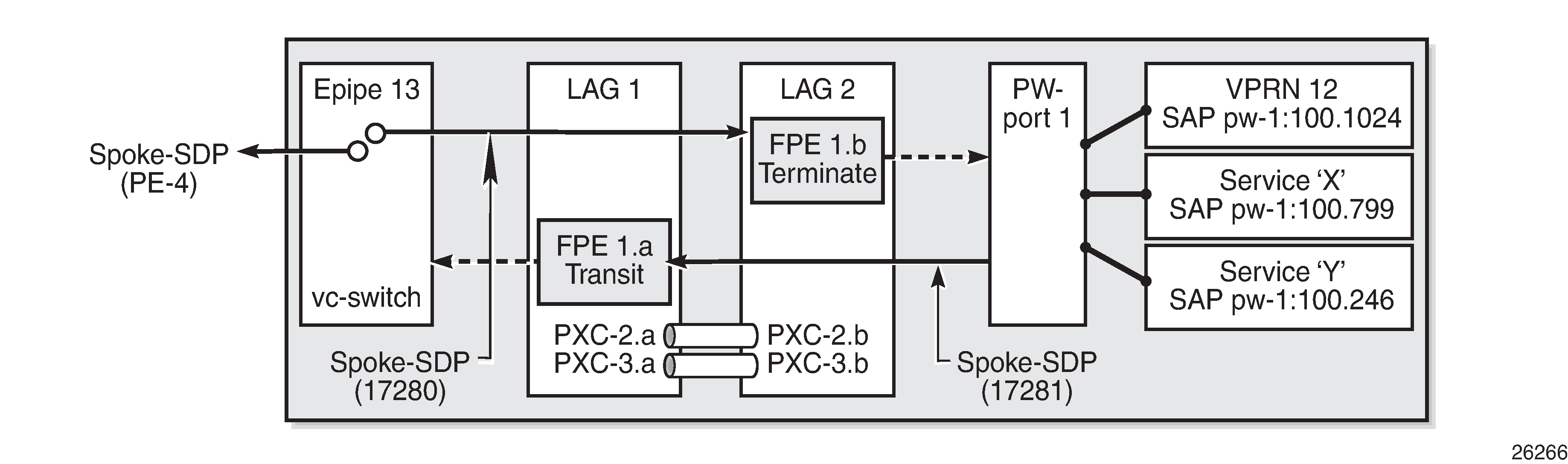
Next, bind the VPRN service to the pw-port with the relevant VLAN delimiters. CE-4 is using SVLAN tag 100 and CVLAN tag 1024 and both VLANs are encapsulated inside the pseudowire as payload. The following VPRN configuration has two interfaces: the first is toward a directly connected test port used to verify IP connectivity, and the second is toward CE-4 and has a SAP with a pw-port syntax. The SAP pw-1:100.1024 represents pw-port 1 with Q-in-Q encapsulation using SVLAN tag 100 and CVLAN tag 1024 as service delimiters. Although not shown (for brevity), a BGP session is configured between PE-5 and CE-4 for route exchange. The remainder of the VPRN parameters are generic and are not explained here.
# on PE-5:
configure
    service
        vprn 12 name "VPRN 12 using PXC AS" customer 1 create
            autonomous-system 64496
            interface "Test-Port-C" create
                address 172.31.105.1/24
                sap 1/1/3:100 create
                exit
            exit
            interface "to-CE-4" create
                address 192.168.45.2/30
                sap pw-1:100.1024 create
                exit
            exit
            bgp-ipvpn
                mpls
                    auto-bind-tunnel
                        resolution any
                    exit
                    route-distinguisher 64496:12
                    vrf-target target:64496:12
                    no shutdown
                exit
            exit
            bgp
                group "EBGP"
            ---snip---
            no shutdown
            exit
        exit
FPE port dimensioning
After the VPRN service at PE-5 is put into a no shutdown state, the EBGP session to CE-4 is established. The relevant routes are exchanged between CE-4 and PE-5 and traffic can be exchanged between test ports B (behind CE-4) and C (connected to PE-5). Initially, traffic is sent unidirectionally from test port C (connected to PE-5) toward port B (connected to CE-4) at a rate of 100 packets/s. To provide a level of entropy for the generated traffic, 100 destination IP addresses are used in the range 172.31.104.2 through 172.31.104.101, and 100 source IP addresses are used in the range 172.31.105.2 through 172.31.105.101.
The following output shows a snapshot of a monitor command against LAG 2 (xc-b, or terminating side) incorporating both physical ports. First, note that the input and output rate of packets per second are equal at 100 packets/s, which is not intuitive for a unidirectional traffic flow. This is because the LAG statistics are essentially a copy of the physical port statistics and the physical port consists of two PXC sub-ports that are looped. Logically, this unidirectional traffic flow is forwarded in a single upstream direction from pxc-2.a/pxc-3.a to pxc-2.b/pxc-3.b. Physically, the unidirectional traffic is transmitted by ports 1/2/2 and 1/2/3, then received by the same ports through the loop. Second, note that traffic is load-balanced over both member links (PXC sub-ports) of the LAG. This is because conventional LAG load-balancing mechanisms are used for the FPE LAG, which in the case of a VPRN SAP-to-network relies on source/destination IP address (with optional Layer 4, which is not currently configured).
*A:PE-5# monitor lag 2 rate interval 3

===============================================================================
Monitor statistics for LAG ID 2
===============================================================================
Port-id      Input packets                    Output packets
             Input bytes                      Output bytes
             Input errors [Input util %]      Output errors [Output util %]
-------------------------------------------------------------------------------
---snip---
-------------------------------------------------------------------------------
At time t = 9 sec (Mode: Rate)
-------------------------------------------------------------------------------
1/2/2!       41                               41
             22041                            22041
             0                         0.00   0                         0.00
1/2/3!       59                               59
             32159                            32159
             0                         0.00   0                         0.00
-------------------------------------------------------------------------------
Totals       100                              100
             54200                            54200
             0                         0.00   0                         0.00
! indicates that the port is assigned to a port-xc.
Traffic is then generated unidirectionally upstream from test port B (connected to CE-4) toward port C (connected to PE-5) at a rate of 100 packets/s. Again, to provide a level of entropy for the generated traffic, 100 destination IP addresses are used in the range 172.31.105.2 through 172.31.105.101, and 100 source IP addresses are used in the range 172.31.104.2 through 172.31.104.101. The input/output rates of packets per second are the same, as previously explained. Again, traffic is load-balanced over both member links (PXC sub-ports). This is because hashing of traffic through a vc-switched Epipe service uses source/destination IP information (and optional Layer 4 information, which is not currently configured).
*A:PE-5# monitor lag 2 rate interval 3

===============================================================================
Monitor statistics for LAG ID 2
===============================================================================
Port-id      Input packets                    Output packets
             Input bytes                      Output bytes
             Input errors [Input util %]      Output errors [Output util %]
-------------------------------------------------------------------------------
---snip---
-------------------------------------------------------------------------------
At time t = 9 sec (Mode: Rate)
-------------------------------------------------------------------------------
1/2/2!       44                               44
             23848                            23848
             0                         0.00   0                         0.00
1/2/3!       56                               56
             30352                            30352
             0                         0.00   0                         0.00
-------------------------------------------------------------------------------
Totals       100                              100
             54200                            54200
             0                         0.00   0                         0.00
! indicates that the port is assigned to a port-xc.
QoS continuity
When using AS mode, the FPE construct creates internal cross-connects between the vc-switching Epipe and the pw-port. These internal cross-connects function as MPLS tunnels that transit through internal network interfaces on the PXC sub-ports. The internal network interfaces use the default network policy 1 for egress marking and ingress classification/FC mapping. Like all default QoS policies, this network policy cannot be modified (or deleted). Also, it is not possible to use a non-default network policy, because there is no router interface to which the non-default policy can be attached.
The internal cross-connects also use the default network-queue policy named "default". While this policy also cannot be modified, it is possible to configure and apply a non-default network-queue policy (including a port-scheduler-policy, if required) at PXC sub-port level. An example of how this would be applied is shown in the following output. Where redundant PXC ports are used in an LAG instance, the queue-policy must be applied to the primary link of the LAG, which is then automatically applied to all other member links. (The primary link of the LAG can be identified using the command "show lag n port".)
# on PE-5:
configure
    port pxc-2.a
        ethernet
            network
                queue-policy "non-default"
            exit
        exit
        no shutdown
    exit
To demonstrate QoS continuity through the FPE, the following is established:
Downstream: Traffic is generated from test port C (connected to PE-5) toward test port B (connected to CE-4) with DiffServ marking EF at a rate of 100 packets/s. At PE-5 SAP ingress, this traffic is mapped into FC EF.
Upstream: Traffic is generated from test port B (connected to CE-4) toward test port C (connected to PE-5) with DiffServ marking EF at a rate of 100 packets/s. At PE-3, a SAP-ingress QoS policy is used to map the traffic into FC EF.
The default network QoS policy 1 is used on all network interfaces at PE-3 and PE-5. On egress, this policy marks FC EF as MPLS EXP 5. On ingress, MPLS EXP 5 is mapped to FC EF.
The default network queue-policy "default" is used on all network interfaces at PE-3 and PE-5. This maps FC EF traffic to queue 6 at ingress and egress.
First, QoS continuity for downstream traffic is validated. The following output shows the relatively simple SAP-egress QoS policy that is applied to the egress of the VPRN interface (pw-port) toward CE-4. No classification of traffic and mapping to FCs are present in the policy, because the classification and mapping have already taken place on the SAP ingress at PE-5 (the SAP facing the test port C).
# on PE-5:
configure
    qos
        sap-egress 12 create
            queue 1 create
                parent "aggregate-rate" level 2 weight 10
            exit
            queue 2 best-effort create
                parent "aggregate-rate" level 2 weight 40 cir-level 2
                rate 5000 cir max
            exit
            queue 3 expedite create
                parent "aggregate-rate" cir-level 3
                rate 2000 cir 2000
            exit
            fc af create
                queue 2
            exit
            fc be create
                queue 1
            exit
            fc ef create
                queue 3
            exit
        exit
The configuration of the Tier 1 scheduler "aggregate-rate" referenced by the child queues in the preceding SAP-egress QoS policy is as follows. The Tier 1 scheduler references a port-scheduler-policy using the command port-parent. Parenting to a port-scheduler is optional, but allows for inclusion of Preamble and IFG in the QoS scheduling algorithm, which otherwise are not included. The Tier 1 scheduler does not directly reference the port-scheduler-policy by name, but rather inherits any port-scheduler configured on the port to which the child queues are mapped. In this example, the port-scheduler-policy "port-scheduler" is applied to PXC sub-port pxc-2.b (terminating side). This is the primary link of LAG 2 and ensures that the same port-scheduler-policy is automatically applied to other member ports.
# on PE-5:
configure
    qos
        port-scheduler-policy "port-scheduler" create
        exit
        scheduler-policy "egress-hqos-scheduler" create
            tier 1
                scheduler "aggregate-rate" create
                    port-parent
                    rate 1
                exit
            exit
       exit
    exit
    port pxc-2.b
        ethernet
            egress-scheduler-policy "port-scheduler"
        exit
        no shutdown
    exit
Finally, the SAP-egress QoS policy is applied to the pw-port SAP within the VPRN. The egress H-QoS scheduler is also attached and an override of the rate is configured.
# on PE-5:
configure
    service
        vprn 12 name "VPRN 12 using PXC AS" customer 1 create
            interface "to-CE-4" create
                sap pw-1:100.1024 create
                    egress
                        scheduler-policy "egress-hqos-scheduler"
                        scheduler-override
                            scheduler "aggregate-rate" create
                                rate 25000
                            exit
                        exit
                        qos 12
                    exit
                exit
            exit
When traffic is generated downstream toward CE-4 in FC EF at a rate of 100 packets/s, the first point of verification is the VPRN pw-port SAP egress. The following output is a monitor of the SAP showing that traffic is correctly mapped to queue 3.
*A:PE-5# monitor service id 12 sap pw-1:100.1024 rate

===============================================================================
Monitor statistics for Service 12 SAP pw-1:100.1024
===============================================================================
---snip---
-------------------------------------------------------------------------------
At time t = 11 sec (Mode: Rate)
-------------------------------------------------------------------------------
---snip---
-------------------------------------------------------------------------------
Sap per Queue Stats
-------------------------------------------------------------------------------
                        Packets                 Octets                  % Port
                                                                        Util.
---snip---
Egress Queue 3
For. In/InplusProf    : 0                       0                       0.00
For. Out/ExcProf      : 100                     51600                   0.04
Dro. In/InplusProf    : 0                       0                       0.00
Dro. Out/ExcProf      : 0                       0                       0.00
Monitoring of network interfaces does not show queue statistics (and is not supported on PXC sub-ports), but a verification of the sub-port statistics on the transit side (LAG 1) shows that packets are incrementing in ingress queue 6 on both sub-ports, as follows:
*A:PE-5# show port pxc-2.a detail | match "Ingress Queue  6" post-lines 4
Ingress Queue  6             Packets                 Octets
     In Profile forwarded  :    711                     382518
     In Profile dropped    :    0                       0
     Out Profile forwarded :    0                       0
     Out Profile dropped   :    0                       0
*A:PE-5# show port pxc-3.a detail | match "Ingress Queue  6" post-lines 4
Ingress Queue  6             Packets                 Octets
     In Profile forwarded  :    404                     217352
     In Profile dropped    :    0                       0
     Out Profile forwarded :    0                       0
     Out Profile dropped   :    0                       0
The last point of verification is the network egress interface toward PE-3. Again, a check at the physical port level shows that packets are incrementing in egress queue 6. Therefore, we can conclude that QoS/FC continuity is maintained in the downstream direction.
*A:PE-5# show port 1/1/2 detail | match "Egress Queue  6" post-lines 4
Egress Queue  6              Packets                 Octets
     In/Inplus Prof fwded  :    2394                    1297548
     In/Inplus Prof dropped:    0                       0
     Out/Exc Prof fwded    :    0                       0
     Out/Exc Prof dropped  :    0                       0
Next, the upstream QoS continuity is verified. PE-3 is marking traffic generated by test port B to FC EF, which in turn is marked as MPLS EXP 5 by PE-3's default network QoS policy. The following output taken at PE-5 shows that packets are incrementing in ingress queue 6 of the network interface toward PE-3 and confirms that traffic is correctly marked as FC EF at ingress.
*A:PE-5# show port 1/1/2 detail | match "Ingress Queue  6" post-lines 4
Ingress Queue  6             Packets                 Octets
     In Profile forwarded  :    3458                    1874236
     In Profile dropped    :    0                       0
     Out Profile forwarded :    0                       0
     Out Profile dropped   :    0                       0
The next point of verification is the egress side of the PXC sub-ports (pxc-2.a and pxc-3.a) forming the transit side (LAG 1). The sub-port statistics verify that packets are incrementing in egress queue 6 of both sub-ports (as traffic is being load-balanced).
*A:PE-5# show port pxc-2.a detail | match "Egress Queue  6" post-lines 4
Egress Queue  6              Packets                 Octets
     In/Inplus Prof fwded  :    12441                   6693258
     In/Inplus Prof dropped:    0                       0
     Out/Exc Prof fwded    :    0                       0
     Out/Exc Prof dropped  :    0                       0
*A:PE-5# show port pxc-3.a detail | match "Egress Queue  6" post-lines 4
Egress Queue  6              Packets                 Octets
     In/Inplus Prof fwded  :    12893                   6936434
     In/Inplus Prof dropped:    0                       0
     Out/Exc Prof fwded    :    0                       0
     Out/Exc Prof dropped  :    0                       0
PXC sub-ports operate in hybrid mode. When the upstream traffic arrives on the PXC sub-ports that form the terminating side of the FPE (pxc-2.b and pxc-3.b), it is mapped to the pw-port SAP-ingress queues, bypassing the ingress network QoS policy and associated ingress network queues. As a result, the MPLS EXP-to-FC mapping cannot be fulfilled and traffic requires reclassification and remapping to the correct FC by the SAP-ingress QoS policy. The following output shows the SAP-ingress QoS policy applied to the pw-port SAP within the VPRN. Because the EXP-to-FC mapping could not be completed, FC reclassification is required in order to map traffic to its original FC before transiting the FPE. In this example, DSCP is used. Also, FC EF is mapped to queue 3.
#on PE-5:
configure
    qos
      sap-ingress 12 create
            queue 1 create
                parent "aggregate-rate" level 2 weight 10
            exit
            queue 2 best-effort create
                parent "aggregate-rate" level 2 weight 40 cir-level 2
                rate 5000 cir max
            exit
            queue 3 expedite create
                parent "aggregate-rate" cir-level 3
                rate 2000 cir 2000
            exit
            queue 11 multipoint create
                rate max cir max
            exit
            fc "af" create
                queue 2
            exit
            fc "be" create
                queue 1
            exit
            fc "ef" create
                queue 3
            exit
            dscp af31 fc "af"
            dscp be fc "be"
            dscp ef fc "ef"
        exit
For completeness, the configuration of the Tier 1 scheduler "aggregate-rate" referenced by the child queues in the preceding SAP-ingress QoS policy is as follows. Unlike the egress counterpart, there is no parenting to a port-scheduler because this is an egress function only.
# on PE-5:
configure
    qos
        scheduler-policy "ingress-hqos-scheduler" create
            tier 1
                scheduler "aggregate-rate" create
                    rate 1
                exit
            exit
        exit
    exit
The SAP-ingress QoS policy is applied to the pw-port SAP within the VPRN, together with the ingress H-QoS scheduler. An override of the scheduler rate is also applied.
# on PE-5:
configure
    service
        vprn 12 name "VPRN 12 using PXC AS" customer 1 create
            interface "to-CE-4" create
                sap pw-1:100.1024 create
                    ingress
                        scheduler-policy "ingress-hqos-scheduler"
                        scheduler-override
                            scheduler "aggregate-rate" create
                                rate 25000
                            exit
                        exit
                        qos 12
                    exit
                exit
            exit
With the SAP-ingress policy applied, a monitor output of the SAP in the following output verifies that the packets are being received in queue 3 at a rate of 100 packets/s. This verifies the FC continuity in the upstream direction, noting that reclassification and remapping of FC is required at SAP ingress.
*A:PE-5# monitor service id 12 sap pw-1:100.1024 rate

===============================================================================
Monitor statistics for Service 12 SAP pw-1:100.1024
===============================================================================
---snip---
-------------------------------------------------------------------------------
Sap Statistics
-------------------------------------------------------------------------------
---snip---
                        Packets                 Octets
---snip---

Ingress Queue 3 (Unicast) (Priority)
Off. HiPrio           : 0                       0                       0.00
Off. LowPrio          : 100                     51647                   0.04
Dro. HiPrio           : 0                       0                       0.00
Dro. LowPrio          : 0                       0                       0.00
For. InProf           : 0                       0                       0.00
For. OutProf          : 100                     51647                   0.04
OAM continuity
The FPE pw-port functionality may be used by redundant routers to provide resilient service termination for a Layer 2 backhaul node implementing a mechanism such as active/standby pseudowire. In SR OS, an active/standby pseudowire is modeled as an Epipe or VPLS service with an endpoint object containing two spoke-SDPs. This form of redundancy relies on the propagation of the Pseudowire Status TLV within an LDP Notification message to convey the operational status of the pseudowires and thereby indicate which one of the pseudowires is active and which one is standby.
The FPE construct uses the concept of a multi-segment pseudowire, implementing Switching-PE (S-PE) functionality to instantiate dynamic cross-connects through the FPE. To verify that LDP status signaling is maintained through this S-PE function, the following is established:
The Epipe service at PE-3 used for Layer 2 backhaul to the FPE is modified to include an endpoint object referenced by two spoke-SDPs.
The first spoke-SDP has a far end of PE-2 and is configured as precedence primary, so becomes the active pseudowire.
The second spoke-SDP has a far end of PE-5 and is configured with the default precedence 4, so becomes the standby pseudowire.
Because the endpoint object is configured for standby-signaling-master, PE-3 will signal a status of standby toward PE-5.
For completeness, the configuration of the Epipe service at PE-3 is as follows:
# on PE-3:
configure
    service
       epipe 13 name "Epipe 13" customer 1 create
            endpoint "redundant-Layer3" create
                standby-signaling-master
            exit
            sap 1/1/3:100.* create
                no shutdown
            exit
            spoke-sdp 32:13 endpoint "redundant-Layer3" create
                precedence primary
                no shutdown
            exit
            spoke-sdp 35:13 endpoint "redundant-Layer3" create
                no shutdown
            exit
            no shutdown
        exit
As shown in the following output, PE-3 has the spoke-SDP to PE-5 (sdp 35:13) as administratively and operationally up, but is signaling a status of standby (pwFwdingStandby).
*A:PE-3# show service id 13 sdp 35:13 detail | match expression
                                           "Local Pw Bits|Peer Pw Bits|Admin State"
Admin State        : Up                       Oper State        : Up
Local Pw Bits      : pwFwdingStandby
Peer Pw Bits       : None
Admin State        : Disabled                 Oper State        : Disabled
At PE-5, the signaled status is acknowledged at the far end of the pseudowire in the Peer Pw Bits field.
*A:PE-5# show service id 13 sdp 53:13 detail | match expression
                                            "Local Pw Bits|Peer Pw Bits|Admin State"
Admin State        : Up                       Oper State        : Up
Local Pw Bits      : None
Peer Pw Bits       : pwFwdingStandby
Admin State        : Disabled                 Oper State        : Disabled
Typically, an S-PE would propagate the status TLV received from one pseudowire segment into the opposing pseudowire segment in order to provide end-to-end status signaling. However, when using FPE, the SR OS Service Manager process correlates between a pseudowire and its corresponding pw-port SAPs, so can take the necessary actions based upon the operational state of each. Therefore, it is not necessary for the S-PE to propagate the status TLV from one segment to another. This is illustrated in the following output at PE-5, which shows the second segment of the multi-segment pseudowire toward the terminating side fpe_1.b. As described, the status bits are not copied between single segments and all local/peer pseudowire bits remain unset.
*A:PE-5# show service id 13 sdp 17280:1 detail | match expression
                                            "Admin State|Peer Pw Bits|Local Pw Bits"
Admin State        : Up                       Oper State        : Up
Local Pw Bits      : None
Peer Pw Bits       : None
Admin State        : Disabled                 Oper State        : Disabled
The pw-port 1 used throughout in this example is internally bound to SDP 17281, as shown in the first of the following outputs. The second output shows that this SDP is operationally down with the flag "stitchingSvcTxDown".
*A:PE-5# show pw-port 1

===================================================================
PW Port Information
===================================================================
PW Port   Encap          SDP:VC-Id               IfIndex
---------------------------------------------------------------------
1         qinq           17281:100001            1526726657
===================================================================
*A:PE-5# show service sdp 17281 detail | match "SDP: 17281 Pw-port: 1" post-lines 10
SDP: 17281 Pw-port: 1
-------------------------------------------------------------------------------
VC-Id                : 100001                Admin Status       : up
Encap                : qinq                  Oper Status        : down
VC Type              : ether
Dot1Q Ethertype      : 0x8100                QinQ Ethertype     : 0x8100
Control Word         : Not Preferred
Entropy Label        : Disabled

Admin Ingress label  : 524281                Admin Egress label : 524282
Oper Flags           : stitchingSvcTxDown
At service level, the first of the following two outputs shows the state of the SAP bound to pw-port 1. As shown, the operational state is down with an indication that this is due to the port being operationally down. The second output shows that this SAP status is propagated to IP interface level because the interface "to-CE-4" is also shown as operationally down.
*A:PE-5# show service id 12 sap pw-1:100.1024 detail | match expression
                                                                "Admin State|Flags"
Admin State        : Up                       Oper State        : Down
Flags              : PortOperDown
*A:PE-5# show router 12 interface "to-CE-4"

===============================================================================
Interface Table (Service: 12)
===============================================================================
Interface-Name                   Adm       Opr(v4/v6)  Mode    Port/SapId
   IP-Address                                                  PfxState
-------------------------------------------------------------------------------
to-CE-4                          Up        Down/Down   VPRN    pw-1:100.1024
   192.168.45.2/30                                             n/a
-------------------------------------------------------------------------------
Interfaces : 1
===============================================================================
To verify a failover, the state of the active/standby pseudowire is transitioned by failing the active pseudowire between PE-3 and PE-2. This causes PE-3 to declare the pseudowire to PE-5 active, which clears the standby status bits. This action causes the SDP (17281) bound to pw-port 1 to become operationally up, followed by pw-port 1 and its associated SAPs, followed by the VPRN IP interface "to-CE-4".
164 2021/05/18 09:43:51.723 UTC MINOR: SVCMGR #2103 Base
"Status of service 2147483649 (customer 1) changed to administrative state: up, operational state: up"

165 2021/05/18 09:43:51.723 UTC MINOR: SVCMGR #2313 Base
"Status of SDP Bind 53:13 in service 13 (customer 1) peer PW status bits changed to none"

166 2021/05/18 09:43:51.724 UTC MAJOR: SVCMGR #2210 Base
"Processing of an access port state change event is finished and the status of all affected SAPs on port pw-1 has been updated."

167 2021/05/18 09:43:51.724 UTC WARNING: SNMP #2005 vprn12 to-CE-4
"Interface to-CE-4 is operational"
This example in the AS mode section illustrated how notification of a downstream failure is propagated through the components of the PXC in AS mode and reflected in the status of the pw-port (and its associated services). Also, if a pw-port fails due to a PXC failure (for example, the physical port fails), it is just as important that the operational state is propagated externally. In the case of pseudowire backhaul (as in the example), this would be achieved by setting the LDP pseudowire status bits to psnIngressFault and psnEgressFault toward the far end.
Conclusion
This chapter demonstrates the principles of PXC configuration. The PXC can be used to provide a relatively simple back-to-back cross-connect operation in DVSM mode, or it can be used in AS mode to provide an integrated path through the FPE with automated cross-connects used to simplify the provisioning process. In both DVSM mode and AS mode, the PXC can be configured as redundant or non-redundant. A relatively simple use-case of terminating an Epipe into a VPRN has been demonstrated for both modes.
There are a large number of use-cases where frame/packet preprocessing is required before service termination. The workaround for these use-cases has previously been a physical external loop, but can now be resolved logically and internally through use of the PXC.