Hybrid OpenFlow Switch
This chapter provides information about Hybrid OpenFlow Switch.
Topics in this chapter include:
Applicability
The information and configuration in this chapter are based on SR OS Release 14.0.R5.
Overview
OpenFlow is defined by the Open Networking Foundation and provides a standard interface between the control layer and forwarding layer of a Software Defined Networking (SDN) architecture. The control layer has northbound interfaces to the application layer and translates the requirements from this layer into low-level control protocols on its southbound interfaces toward the forwarding layer. Made up of SDN controllers, the control layer provides an abstraction between the application layer and the forwarding layer. The forwarding layer may consist of physical and/or virtual network elements.
An OpenFlow controller operates at the control layer while an OpenFlow switch operates at the forwarding layer, and the OpenFlow protocol is used for communication between them. The term Hybrid OpenFlow switch refers to switches or routers that fully integrate both OpenFlow operation and conventional Ethernet switching or IP routing. Conversely, OpenFlow-only switches support only OpenFlow operations. SR OS platforms operate as Hybrid OpenFlow switches.
An OpenFlow switch may have one or more flow tables, each of which contains one or more flow entries. A flow is a sequence of packets that matches a specific entry in a flow table. When a packet is processed by a flow table, it is matched against flow entries that contain match fields and a priority to uniquely identify each entry. Match fields consist of criteria to match against a packet, such as ingress port/VLAN, source/destination IP address, protocol, or source/destination port.
The sequence with which a packet is parsed through a flow table that consists of multiple flow entries depends on the priority of each flow entry. The highest priority flow entry is processed first, and if no match is found, the packet continues to the next highest flow entry until a packet is either matched by a flow entry or all flow entries are parsed and no match is found. Priority 0 is reserved for the table-miss flow entry, which is used when a packet does not match any other flow entries in the flow table. In this case, the packet could be forwarded, dropped, or sent to the OpenFlow controller using a Packet-In message.
Each flow entry consists of one or more OpenFlow Protocol Instruction Types (OFPITs) that collectively form an instruction set. The instruction type defines the type of action to be taken, such as Write-Action, Write-Metadata, or Clear-Action. Each instruction type contains an OpenFlow Protocol Action Type (OFPAT), and the group of actions associated with a flow entry is referred to as an action set. These actions may be to manipulate a packet, or rate-limit packets matching this flow entry, or to output to a specific port, where port may be physical, logical (such as an MPLS or VXLAN tunnel), or a reserved port (such as the control channel with the OpenFlow controller).
Each flow entry is also associated with a 64-bit opaque cookie value assigned by the OpenFlow controller. However, this cookie value is not used for packet lookup or processing. Its purpose is to enable the controller to filter flow statistics and for flow modification/deletion. In SR OS, the cookie value is also used to distinguish between flow entries associated with the base routing instance and those associated with services, as described in more detail later in this chapter.
OpenFlow Protocol
The OpenFlow channel is the interface that connects the OpenFlow switch to a controller and runs over TCP port 6653. By default, the OpenFlow channel is a single TCP connection, but auxiliary connections are also supported. These auxiliary connections may be used for general OpenFlow messages, but are intended to allow for parallel processing of statistics requests and Packet-In messages. Auxiliary connections use the same destination IP address and destination port as the main channel, but are uniquely identified by having a different combination of the switch Datapath ID and an Auxiliary ID on the OpenFlow switch.
The Datapath ID is an 8-byte value used to uniquely identify the switch. To construct it, SR OS uses a concatenation of the OpenFlow switch instance ID (2 bytes) and the chassis MAC (6 bytes). Because the Datapath ID is a switch-wide parameter, it is common to all connections from a switch, but the Auxiliary ID is unique for each channel. In SR OS, the primary channel uses an Auxiliary ID of zero, while auxiliary channels use a unique non-zero value. The Datapath ID and Auxiliary ID are exchanged during the connection setup. After the OpenFlow session is established and Hello messages exchanged, the controller requests a list of supported features from the switch (using an OFPT_FEATURES_REQUEST message). The response from the switch (OFPT_FEATURES_REPLY) contains (among other things) the Datapath ID and Auxiliary ID.
The OpenFlow protocol supports three message types: controller-to-switch, asynchronous, and symmetric.
Controller-to-switch messages are initiated by the controller and are used to manage or inspect the state of the OpenFlow switch.
Asynchronous messages are initiated by the switch and are used to notify the controller of network events and changes to switch state.
Symmetric messages are initiated by either switch or controller and are sent in an unsolicited manner.
OpenFlow specifies the use of a number of different messages within its operation and the use of these messages is constrained to the message type to which they are associated. Table 1 lists the various OpenFlow messages associated with each message type, with a brief description of its usage. Some of the messages will be referred to throughout this chapter, with examples of how and when they are used.
Message Type |
Message |
Description |
|---|---|---|
Controller-to-switch |
Feature |
[OFPT_FEATURES_REQUEST/REPLY] Used by controller to query capabilities of the switch. Typically used on session establishment. |
Configuration |
[OFPT_GET_CONFIG_REQUEST/REPLY, OFPT_SET_CONFIG] Used to set and query configuration parameters in the switch. |
|
Modify-State |
[OFPT_FLOW/PORT/TABLE_MOD] Used to add, delete, and modify flow entries in the OpenFlow tables. |
|
Read-State |
Used to collect information such as configuration, statistics, and capabilities from the switch. |
|
Packet-Out |
[OFPT_PACKET_OUT] Used by the controller to send packets out of a specific port on the switch, and to forward packets received in Packet-In messages. |
|
Barrier |
[OFPT_BARRIER_REQUEST/REPLY] Used to ensure that messages prior to the barrier are processed before any messages after the barrier. Allows for ordering of message processing. |
|
Role-Request |
[OFPT_ROLE_REQUEST/REPLY] Used to set the role of the OpenFlow channel. Can be Master, Slave, or Equal. When multiple controllers are used, only one can be set to Master. |
|
Asynchronous-Configuration |
[OFPT_GET_ASYNC_REQUEST/REPLY, OFPT_SET_ASYNC] Used by the controller to set a filter on the asynchronous messages that it needs to receive. |
|
Asynchronous |
Packet-In |
[OFPT_PACKET_IN] Used to transfer a packet to the controller (for example, a table-miss flow entry). |
Flow-Removed |
[OFPT_FLOW_REMOVED] Used to notify the controller that a flow entry has been removed from the flow table. |
|
Port-Status |
[OFPT_PORT_STATUS] Used to notify the controller of a change in the configuration or status of a port. |
|
Error |
[OFPT_ERROR] Used to notify the controller of an error. |
|
Symmetric |
Hello |
[OFPT_HELLO] Exchanged between controller and switch during session startup. |
Echo |
[OFPT_ECHO_REQUEST/REPLY] Used to maintain the liveliness of the OpenFlow channel. |
|
Experimenter |
[OFPT_EXPERIMENTER] Provides a standard way to offer additional proprietary functionality within the standard message space. |
OpenFlow messages have a standard header that includes the version of the protocol. SR OS supports OpenFlow specification 1.3.1, which requires the use of OpenFlow protocol version 4. Although the OpenFlow protocol defines the standard through which controllers and switches should communicate, it also allows for additional functionality to be implemented, using Experimenter messages and fields. SR OS uses Experimenter fields as additional match criteria and action types.
Configuration
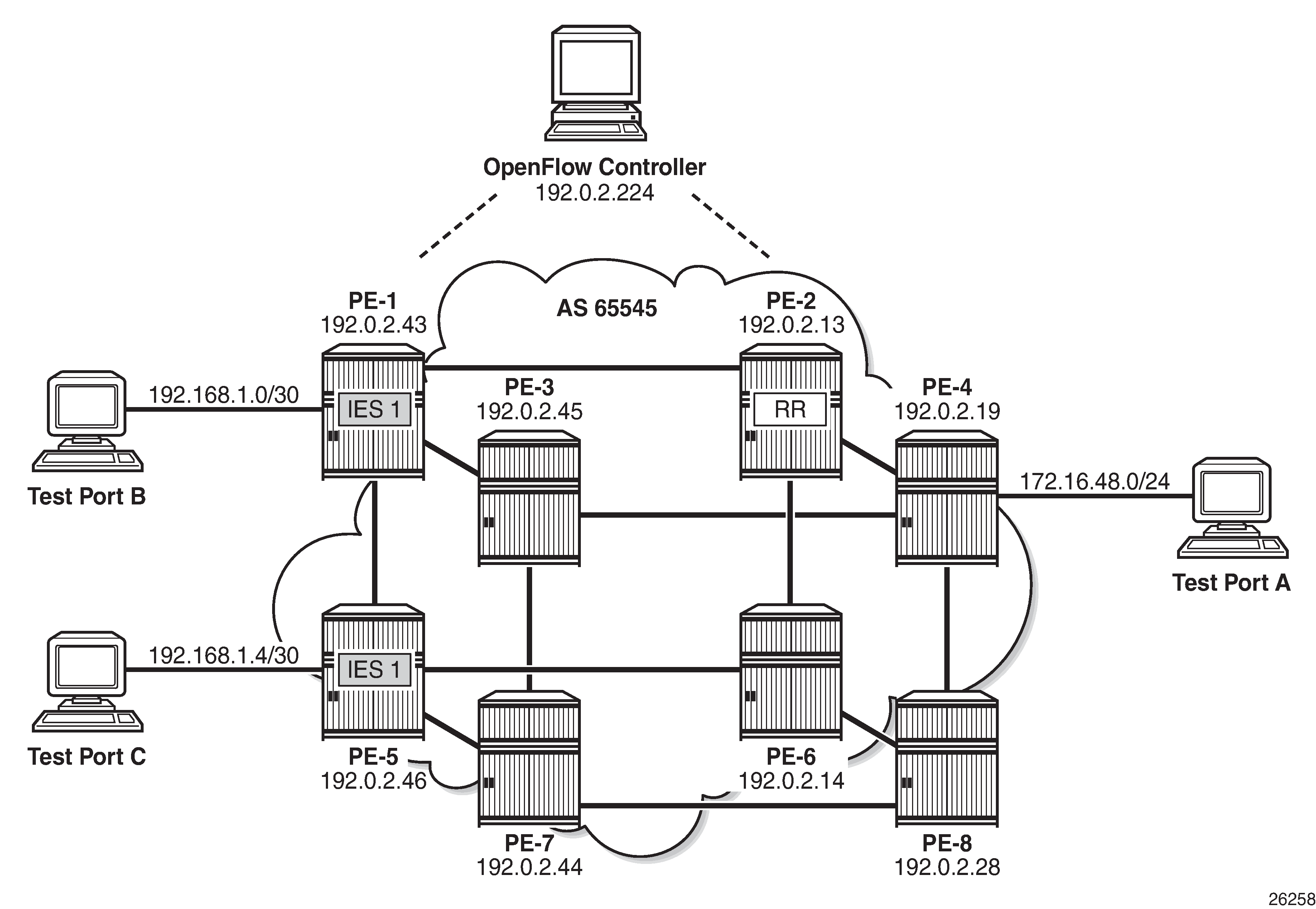
Example Topology shows an example topology to demonstrate the use of OpenFlow. PE routers PE-1 through PE-8 form part of AS 65545 and run IS-IS and RSVP. All PE routers are IBGP clients of a Route Reflector situated at PE-2 for the IPv4 and VPN-IPv4 address families. An OpenFlow Controller is at address 192.0.2.224, which is reachable from AS 65545. Test port A is connected to PE-4, and test ports B and C are connected to PE-1 and PE-5, respectively. These test ports will be configured to advertise routes and source/sink traffic within the base and service routing contexts to verify OpenFlow operation. More information about specific configurations will be provided within the relevant parts of this chapter.
OpenFlow Switch Configuration
OpenFlow specification 1.3.1 allows for multiple flow tables within an OpenFlow switch that are sequentially numbered starting at zero. A function referred to as pipeline processing subsequently matches packets, first against flow entries of flow table 0, but allows for instructions to optionally direct a packet to another flow table, where the process is repeated. Up to eight Hybrid OpenFlow switch instances can be supported per system. Each switch instance supports a single flow table: table 0.
Flow entries pushed from an OpenFlow controller are dynamically embedded within ingress IP filters provisioned on the system. Within the OpenFlow specification, there is no provision for enabling context-specific flow entries. That is, it is not possible to enable a flow entry explicitly within the base routing context, or enable a flow entry explicitly within a service or VPN context. To overcome this, and provide maximum flexibility without the requirement for proprietary extensions, SR OS makes intelligent use of the 64-bit cookie value that is associated with every flow entry in a Modify Flow Entry (OFPT_FLOW_MOD) message. The high-order 32 bits of the value are subdivided into two parts. Bits 63 to 60 are used to determine whether the flow entry is applicable to a filter on an IES or router interface in the base routing context (also referred to as the Global Routing Table [GRT]), or a System filter, or a filter applied within a VPRN or VPLS service context. For the latter, bits 59 to 32 are then used to define the service ID value. This use of the cookie value in this manner is referred to as a multi-service OpenFlow switch instance.
Bits 63 to 60 |
Bits 59 to 32 |
Bits 31 to 0 |
SR OS context |
|---|---|---|---|
0000 |
0 |
Arbitrary |
Used by filters in base router |
1000 |
0 |
Arbitrary |
Used by System filter policy |
1100 |
Service ID value |
Arbitrary |
Used by filters policies within specified service |
The use of a System filter allows for a common rule set defined in an IP filter with a scope of System to be embedded in multiple interface filters, reducing configuration requirements and increasing system scale. The use of System filters is not described within this chapter.
The following output shows the configuration required to define the Hybrid OpenFlow switch and to establish connectivity with the OpenFlow controller:
configure
    open-flow
        of-switch "ofs-1"
            aux-channel-enable
            controller 192.0.2.224:6653
            flowtable 0
                switch-defined-cookie
                max-size 4096
            exit
            logical-port-status rsvp-te
            no shutdown
        exit
    exit
The of-switch command allows for the creation of a switch instance and requires a name of 1 to 32 characters. This creates a new of-switch context under which the characteristics of the switch are defined. The controller command requires the destination IP address and port of the OpenFlow controller to be entered, separated by a colon. Port 6653 is the standard IANA assigned port for OpenFlow. When this connection is successfully established, it creates the primary channel (with Auxiliary-ID 0) only.
The output shows the configuration of a single controller, but it is possible to configure multiple controllers for redundancy; each controller may create/modify/delete flows entries in the flow table of this switch instance. Also, the OpenFlow switch can use both in-band (base routing context) and out-of-band (management routing context) to establish connectivity with the controller, with preference given to out-of-band if a valid route exists.
The aux-channel-enable command establishes the auxiliary channels. When enabled, this command creates an auxiliary channel for statistics with Auxiliary-ID 1, and an auxiliary channel for Packet-In messages with Auxiliary-ID 2. Although these auxiliary channels are assigned an explicit purpose, the switch will still accept any generic OpenFlow messages over these auxiliary channels and will respond in return on the same channel. The flowtable command modifies the characteristics of flow table 0. The max-size command configures a limit on the number of flow entries that can be populated within each flow-table. Flow-table entries are created in hardware on the line-card datapath and consume Content-Addressable Memory (CAM) entries; therefore, placing a limit on how much of that resource is used by OpenFlow may be needed. The switch-defined-cookie command enables the use of a multi-instance OpenFlow switch. This is the recommended approach for deploying an OpenFlow switch in SR OS; it allows for creation of service-specific flow entries, and offers an increased number of traffic actions. Finally, the logical-port-status rsvp-te command instructs the switch to report configuration and/or state changes to RSVP-TE logical ports to the controller, which is achieved using asynchronous Port-Status (OFPT_PORT_STATUS) messages.
When the OpenFlow switch is put into a no shutdown state, its operational state can be verified with the command shown in the following output:
*B:PE-4# show open-flow of-switch "ofs-1" status

===============================================================================
Open Flow Switch Information
===============================================================================
Switch Name        : ofs-1
Data Path ID       : 00030ca40202d401    Admin Status       : Up
Echo Interval      : 10 seconds          Echo Multiple      : 3
Logical Port Type  : rsvp-te
Buffer Size        : 0                   Num. of Tables     : 1
Description        : (Not Specified)
Capabilities Supp. : flow-stats table-stats port-stats
Aux Channel Enabled: True
===============================================================================
The output shows the switch Datapath ID, which together with the Auxiliary ID uniquely identifies a (primary/auxiliary) channel between switch and controller. The output also shows the logical port types in use as being RSVP-TE, support for a single flow table, and a buffer size of 0. The buffer size is used when Packet-In messages are used for a table-miss.
The OpenFlow specification provides an option for a switch to truncate the packet and send only a portion of the packet to the controller in a Packet-In message, together with a buffer-ID, while the remainder of the packet is buffered. When the controller subsequently responds with a Packet-Out message containing a corresponding buffer-ID, the packet is retracted from buffer, re-assembled, and forwarded through the port specified in the Packet-Out message. Rather than buffering, SR OS sends the complete packet to the controller in a Packet-In message, so requires no buffer. Also, SR OS sends only the first packet of a flow in a Packet-In message; any subsequent packets of that flow are dropped at ingress. This avoids overwhelming the controller with table-miss packets, and equally offers a level of protection to the CPM. The expectation is that the controller should create a new flow entry for that flow.
The following output shows the status of the OpenFlow channel to the controller:
*B:PE-4# show open-flow of-switch "ofs-1" controller 192.0.2.224:6653 detail

===============================================================================
Open Flow Controller Information
===============================================================================
IP Address            : 192.0.2.224       Port              : 6653
Role                  : equal
Generation ID         : 0

-------------------------------------------------------------------------------
Open Flow Channel Information - Channel ID(1)
-------------------------------------------------------------------------------
Channel ID        : 1                 Version           : 4
Connection Type   : primary           Operational Status: Up
Auxiliary ID      : 0
Source Address    : 192.0.2.19        Source Port       : 56261
Operational Flags : socket-state-established hello-received hello-transmitted
                    handshake
Async Fltr Packet In
 (Master or Equal): table-miss apply-action
 (Slave)          : (Not Specified)
Async Fltr Port Status
 (Master or Equal): port-add port-delete port-modify
 (Slave)          : port-add port-delete port-modify
Async Fltr Flow Rem
 (Master or Equal): idle-time-out hard-time-out flow-mod-delete group-delete
 (Slave)          : (Not Specified)
Echo Time Expiry  : 0d 00:00:01       Hold Time Expiry  : 0d 00:00:21
Conn. Uptime      : 0d 06:09:59       Conn. Retry       : 0d 00:00:00

-------------------------------------------------------------------------------
Open Flow Channel Stats - Channel ID(1)
-------------------------------------------------------------------------------
Packet Type      Transmitted Packets  Received Packets     Error Packets
-------------------------------------------------------------------------------
Hello            1                    1                    0
Error            1                    0                    0
Echo Request     1722                 508                  0
Echo Reply       508                  1722                 0
Experimenter     0                    0                    0
Feat. Request    0                    1                    0
Feat. Reply      1                    0                    0
---snip---
The complete output would show the details of all the OpenFlow channels between the switch and the controller. As the aux-channel-enable command is configured, there are three channels in total, but only the primary channel (Auxiliary ID 0) is shown for brevity.
Each controller is assigned a role, which can be master, slave, or equal, with the default being equal. The role determines what access the controller has to the switch and also what asynchronous messages the switch should forward to the controller:
Equal role: The controller has full access to the switch and is considered equal to other controllers in the same role. All controllers should receive asynchronous messages from the switch.
Slave role: The controller has read-only access to the switch. Controllers do not receive asynchronous messages from the switch apart from Port-Status messages.
Master role: The controller has full access to the switch, but only one controller can have the role of master.
If a controller changes its role to master using a Role-Request (OFPT_ROLE_REQUEST) message, the switch modifies all other connections to the role of slave. To ensure that the switch has the latest information on a controller mastership election, controllers coordinate the assignment of a Generation ID, also shown in the output. The Generation ID is a monotonically increasing 64-bit counter; therefore, any OFPT_ROLE_REQUEST message received with a role of master or slave with Generation ID of a lower value than one previously received is ignored.
The version, connection type, and Auxiliary ID have been previously described.
The output shows asynchronous filters (Async Fltr), dependent on the role that the controller is playing. A controller may use Asynchronous Configuration (OFPT_SET_ASYNC) messages to set a filter on the asynchronous messages that it receives from the switch. In the absence of an OFPT_SET_ASYNC message from the controller, the switch sets an initial configuration of asynchronous messages for Packet-In, Port-Status, and Flow-Removal messages and this configuration is shown. The remainder of the output (again truncated) shows detailed statistics for all message types sent and received over this channel.
Dynamic Flow Entry Creation
With the basic switch configured and a channel established to the controller, the next step is to configure one or more IP filters that allow for dynamic embedding of OpenFlow flow entries. The following section will describe flow entries created in the base routing instance (also referred to as GRT), followed by entries created within a service instance.
Base Routing Instance
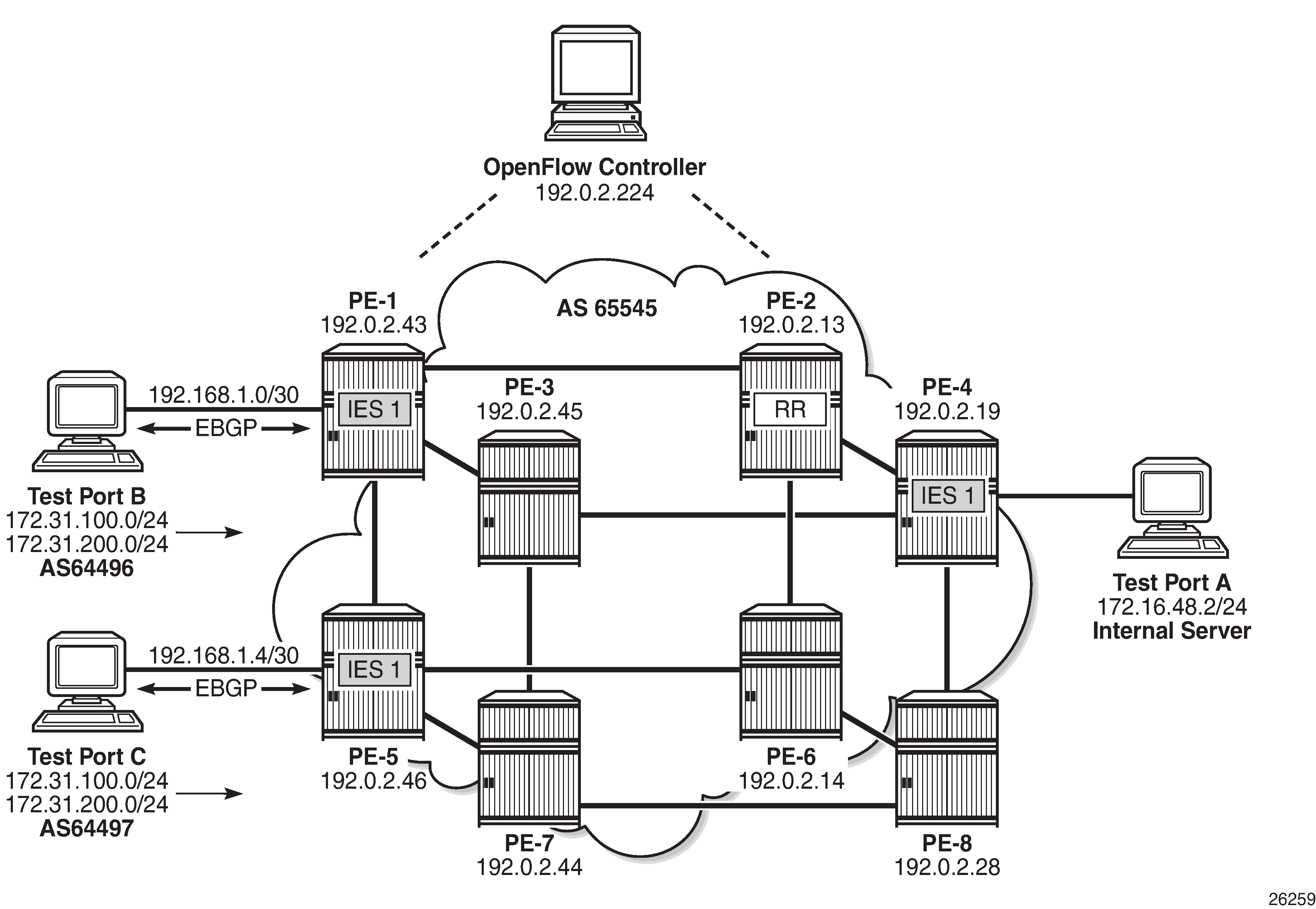
To generate rules within the base routing instance, the example topology is configured as shown in OpenFlow Operation in Base Routing Context. Test ports B and C simulate external peers located in AS 64496 and 64497, respectively. Both external peers advertise prefixes 172.31.100.0/24 and 172.31.200.0/24 to AS 64496, which are propagated internally within AS 65545. PE-4 hosts an internal server on subnet 172.16.48.0/24, which is advertised to the external peers. All three test ports are indexed to IES 1 at the corresponding PE router. BGP is configured within AS 65545 such that next-hops are resolved to shortcut tunnels using RSVP.
An IP filter is configured using the embed-filter open-flow command to allow for dynamic embedding of flow entries by an OpenFlow switch instance. In this example, the OpenFlow switch is the previously configured ofs-1. IP filters allow dynamically embedded OpenFlow filter entries to co-exist with static filter entries and other dynamic filter entries created by Flowspec or RADIUS. Therefore, an offset is defined that specifies the start point for dynamically created OpenFlow entries. This ensures that the OpenFlow flow entries can be isolated from other dynamic and static filter entries; FlowSpec filter entries must be created after static entries. In this example, the offset is 100.
configure
    filter
        ip-filter 10 create
            description "OpenFlow Basic GRT Filter"
            embed-filter open-flow "ofs-1" offset 100
        exit
    exit
The filter is applied as an ingress filter at PE-4 on the SAP connecting test port A, as follows:
configure
    service
        ies 1 customer 1 create
            interface "Test-Port-A" create
                address 172.16.48.1/24
                sap 3/1/4:10 create
                    ingress
                        filter ip 10
                    exit
                exit
Before any flow entries are initiated from the controller, a single entry with ID 65535 (maximum) is automatically populated in the embedding filter. This entry is inserted by OpenFlow when the embed-filter open-flow command is configured in the filter context and represents the table-miss entry. When OpenFlow uses filters, it ignores any default-action that may be configured in the filter so that filters can be chained. However, a table-miss action must exist and this is represented by entry 65535.
The source/destination addresses are 0.0.0.0/0 and the default primary action is forward (also referred to as fall-through). This primary action is configurable using the no-match-action command within the flowtable 0 context. Other actions include packet-in or drop. When packet-in is configured and a packet of a flow matches entry 65535 (table-miss), SR OS sends only the first packet of that flow to the controller in a Packet-In message, while subsequent packets of that same flow are dropped.
*B:PE-4# show filter ip 10
===============================================================================
IP Filter
===============================================================================
Filter Id           : 10                           Applied        : Yes
Scope               : Template                     Def. Action    : Drop
System filter       : Unchained
Radius Ins Pt       : n/a
CrCtl. Ins Pt       : n/a
RadSh. Ins Pt       : n/a
PccRl. Ins Pt       : n/a
Entries             : 0/0/0/1 (Fixed/Radius/Cc/Embedded)
Description         : OpenFlow Basic GRT Filter
-------------------------------------------------------------------------------
Filter Match Criteria : IP
-------------------------------------------------------------------------------
Entry               : 65535
Origin              : Inserted by open-flow (no-match-action)
Description         : (Not Specified)
Log Id              : n/a
Src. IP             : 0.0.0.0/0
Src. Port           : n/a
Dest. IP            : 0.0.0.0/0
Dest. Port          : n/a
Protocol            : Undefined                    Dscp           : Undefined
ICMP Type           : Undefined                    ICMP Code      : Undefined
Fragment            : Off                          Src Route Opt  : Off
Sampling            : Off                          Int. Sampling  : On
IP-Option           : 0/0                          Multiple Option: Off
TCP-syn             : Off                          TCP-ack        : Off
Option-pres         : Off
Egress PBR          : Disabled
Primary Action      : Forward
Ing. Matches        : 0 pkts
Egr. Matches        : 0 pkts

===============================================================================
An OpenFlow IP filter is also automatically created by the system with a filter ID of _tmnx_ofs_<name>:<number>, where <name> is the name of the OpenFlow switch instance and <number> is a numerical integer. This is shown in the following output as _tmnx_ofs_ofs-1:8. This system-created filter ID contains all of the active flow entries dynamically created by the OpenFlow switch ofs-1 for the base (GRT) context, effectively acting as a repository for that routing context.
Any filter that is subsequently configured to dynamically embed GRT OpenFlow filter entries from the same OpenFlow switch instance will inherit all of the current entries contained in this filter. That is, if a new filter is configured to embed GRT OpenFlow entries from ofs-1, all of the flow-entries contained in _tmnx_ofs_ofs-1:8 will be automatically cloned into that new filter. There is no requirement for any active flow entries to be re-sent by the controller in order to populate this new filter. This approach allows filters to be enabled for OpenFlow embedding before or after flow entries have been received by the OpenFlow switch, thereby removing any order dependency.
*B:PE-4# show filter ip filter-type openflow
===============================================================================
Openflow IP Filters                                              Total:     1
===============================================================================
Filter-Id                     Description
-------------------------------------------------------------------------------
_tmnx_ofs_ofs-1:8             Filter for OFS 'ofs-1' for grt context
OpenFlow Filtering in Action
Before initiating any flow entries from the controller, the following traffic flows are sourced from test port A connected to PE-4.
A UDP-based flow with a destination IP address of 172.31.100.1/24 at a rate of 1000 packets/s.
A UDP-based flow with a destination address of 172.31.200.1/24, again at a rate of 1000 packets/s.
Both test port B and C are advertising the preceding prefixes, which are advertised internally by PE-1 and PE-5, respectively. At PE-4, the preferred next-hop for these prefixes is PE-1 (192.0.2.43).
*B:PE-4# show router bgp routes 172.31.0.0/16 longer
===============================================================================
 BGP Router ID:192.0.2.19       AS:65545       Local AS:65545
===============================================================================
 Legend -
 Status codes  : u - used, s - suppressed, h - history, d - decayed, * - valid
                 l - leaked, x - stale, > - best, b - backup, p - purge
 Origin codes  : i - IGP, e - EGP, ? - incomplete
===============================================================================
BGP IPv4 Routes
===============================================================================
Flag  Network                                            LocalPref   MED
      Nexthop (Router)                                   Path-Id     Label
      As-Path
-------------------------------------------------------------------------------
u*>i  172.31.100.0/24                                    100         0
      192.0.2.43                                         None        -
      64496 64500
u*>i  172.31.200.0/24                                    100         0
      192.0.2.43                                         None        -
      64496 64500
-------------------------------------------------------------------------------
Routes : 2
===============================================================================
BGP next-hops are resolved to RSVP shortcut tunnels. For this test, there are two RSVP LSPs, one to PE-1 and one to PE-5, and they are viewed as logical ports by the OpenFlow switch. Because PE-1 is the preferred next-hop for the advertised prefixes, this resolves to the LSP named PE-4-PE-1-RSVP.
*B:PE-4# show open-flow of-switch "ofs-1" port
===============================================================================
Open Flow Port Stats
===============================================================================
Port ID        Type           Transmitted Packets      Transmitted Bytes
Port Name
-------------------------------------------------------------------------------
1073741833     logical        0                        0
PE-4-PE-1-RSVP
1073741834     logical        0                        0
PE-4-PE-5-RSVP
===============================================================================
The following output shows, as expected, that PE-1 is egressing traffic at a rate of 2000 packets/s toward test port B, representing the sum of the two 1000 packets/s test streams.
B:PE-1# monitor service id 1 sap 5/1/3:10 rate
===============================================================================
Monitor statistics for Service 1 SAP 5/1/3:10
===============================================================================
---snip---
-------------------------------------------------------------------------------
At time t = 11 sec (Mode: Rate)
-------------------------------------------------------------------------------
                        Packets                 Octets                  % Port
                                                                        Util.
Egress Queue 1
For. In/InplusProf    : 0                       7                       ~0.00
For. Out/ExcProf      : 2000                    1023907                 0.08
Dro. In/InplusProf    : 0                       0                       0.00
Dro. Out/ExcProf      : 0                       0                       0.00
The controller initiates an OFPT_FLOW_MOD message containing an OFPFC_ADD command to the switch to create a new flow entry. The flow entry is viewed using the command shown in the following output:
*B:PE-4# tools dump open-flow of-switch "ofs-1"
===============================================================================
Switch: ofs-1
===============================================================================
Table     : 0                           Flow Pri  : 0
Cookie    : 0x0000000000000000          CookieType: grt
Controller: :::0
Filter Hnd: 0xC30000080000FFFF
Filter    : _tmnx_ofs_ofs-1:8 entry 65535

In Port   : *
VID       : *                           Outer VID : *
EthType   : *
Src IP    : *
Dst IP    : *
IP Proto  : *                           DSCP      : *
Src Port  : *                           Dst Port  : *
ICMP Type : *                           ICMP Code : *
Label     : *
IPv6ExtHdr: (Not Specified)

Action    : Fall-through

Flow Flags: IPv4/6 [!E] [RO] [DEF]
Up Time   : 0d 00:18:47                 Add TS    : 405757580
Mod TS    : 0                           Stats TS  : 405870240
#Packets  : 1638207                     #Bytes    : 838761984
-------------------------------------------------------------------------------
Table     : 0                           Flow Pri  : 1635
Cookie    : 0x0000000000000100          CookieType: grt
Controller: 192.0.2.224:6653
Filter Hnd: 0x830000080000F99C
Filter    : _tmnx_ofs_ofs-1:8 entry 63900

In Port   : *
VID       : *                           Outer VID : *
EthType   : 0x0800
Src IP    : *
Dst IP    : 172.31.100.0/24
IP Proto  : *                           DSCP      : *
Src Port  : *                           Dst Port  : *
ICMP Type : *                           ICMP Code : *
Label     : *

Action    : Forward LspId 10
            Lsp PE-4-PE-5-RSVP

Flow Flags: IPv4 [FR]
Up Time   : 0d 00:01:57                 Add TS    : 405858646
Mod TS    : 0                           Stats TS  : 405870241
#Packets  : 115951                      #Bytes    : 59366912
-------------------------------------------------------------------------------
Number of flows: 2
===============================================================================
The first flow entry shown is the table-miss entry with an action of fall-through (or forward). The second entry contains the new flow entry.
The cookie associated with the message has a value of 0x0000000000000100 and, as shown in Table 2, because the high-order bits are set to zero, the cookie represents a flow entry that is used by filters within the base routing instance (shown as Global Routing Table or GRT). The filter used by this flow entry is _tmnx_ofs_ofs-1:8. This is the system-created OpenFlow IP filter for OpenFlow switch ofs-1 and contains all active GRT flow entries for that switch. Any filters that embed GRT OpenFlow entries from switch instance ofs-1 will automatically inherit all the active flow entries contained within this filter. In this example, the flow entries in _tmnx_ofs_ofs-1:8 are inherited only by IP filter 10. In addition, IP filter 10 will include ingress packets/bytes matched for each entry.
The priority field indicates a value of 1635 and, as previously described, determines the order with which flow entries are processed. Because OpenFlow states that the highest priority should be processed first and SR OS processes packets starting with the lowest numeric entry ID within a filter, the formula [65535 - flow_priority + embedding offset] is used to convert the cookie priority into a filter entry ID. This yields a filter entry ID of 63900. When a packet matches an entry in the filter, the packet is subject to the action defined in that entry, and is not subject to further filter entry processing.
The OpenFlow match fields specify an Ethertype of IPv4 (0x0800) and a destination prefix of 172.31.100.0/24, which are converted directly into filter entry match criteria. The OpenFlow instruction type is Write_Actions (OFPIT_WRITE_ACTIONS) in order to create the new flow, and has an action type of Output (OFPAT_OUTPUT). The output is directed to a (logical) port, which is the LSP PE-4-PE-5-RSVP.
The Modify Flow Entry (OFPT_FLOW_MOD) message contains a field for flags that are associated with each flow entry. These flags, together with some internal flags, are indicated in the Flow Flags field. Their meanings are described in Table 3.
Flag |
Meaning |
Description |
|---|---|---|
!E |
Not evictable |
Entry cannot be removed. |
RO |
Read only |
Entry cannot be modified. |
DEF |
Default |
|
FR |
SEND_FLOW_REM |
If set, the switch must send a Flow-Removed message when the flow entry is deleted. |
CO |
CHECK_OVERLAP |
If set, the switch must check that there are no conflicting entries with the same priority before inserting it into the flow entry table. An error is returned if a conflict exists. |
RC |
RESET_COUNTS |
Reset flow packet and byte counts. |
!PC |
NO_PKT_COUNTS |
When set, the switch does not need to keep track of the flow packet count. |
!BC |
NO_BYT_COUNTS |
When set, the switch does not need to keep track of the byte count. |
The dynamic OpenFlow flow entry redirecting traffic destined for prefix 172.31.100.0/24 is now in place as entry 63900 within IP filter _tmnx_ofs_ofs-1:8, and subsequently IP filter 10. The following two outputs show a monitor command run against PE-1's SAP toward test port B and PE-5's SAP toward test port C. Both SAPs are equally spreading the load of the two test streams of 1000 packets/s. Traffic for prefix 172.31.200.0/24 is routed toward PE-1 based on a route-table lookup. Traffic for prefix 172.31.100.0/24 is forwarded to PE-5 as a result of the OpenFlow redirect.
*A:PE-5# monitor service id 1 sap lag-1:10 rate
===============================================================================
Monitor statistics for Service 1 SAP lag-1:10
===============================================================================
---snip---
                        Packets                 Octets                  % Port
                                                                        Util.
Egress Queue 1
For. In/InplusProf    : 0                       0                       0.00
For. Out/ExcProf      : 1000                    512186                  0.04
Dro. In/InplusProf    : 0                       0                       0.00
Dro. Out/ExcProf      : 0                       0                       0.00
B:PE-1# monitor service id 1 sap 5/1/3:10 rate
===============================================================================
Monitor statistics for Service 1 SAP 5/1/3:10
===============================================================================
---snip---
                        Packets                 Octets                  % Port
                                                                       Util.
Egress Queue 1
For. In/InplusProf    : 0                       7                       ~0.00
For. Out/ExcProf      : 1000                    512186                  0.04
Dro. In/InplusProf    : 0                       0                       0.00
Dro. Out/ExcProf      : 0                       0                       0.00
FLOW_MOD messages allow for flow entries to be associated with hard and idle timeouts, which are not currently used by SR OS. Although timeout values can be passed by a controller in a FLOW_MOD message, they are effectively ignored. As a result, dynamic flow entries remain in place as filter entries until removed by the controller, or the OpenFlow switch instance is placed in a shutdown state. If the LSP transitions to an operationally down state while the redirect flow entry is still active, the switch will notify the controller of the change of state using a Port-Status message, and traffic will be subject to a forward action. If the LSP becomes operational again, the flow entry becomes active again.
Service Routing Instance
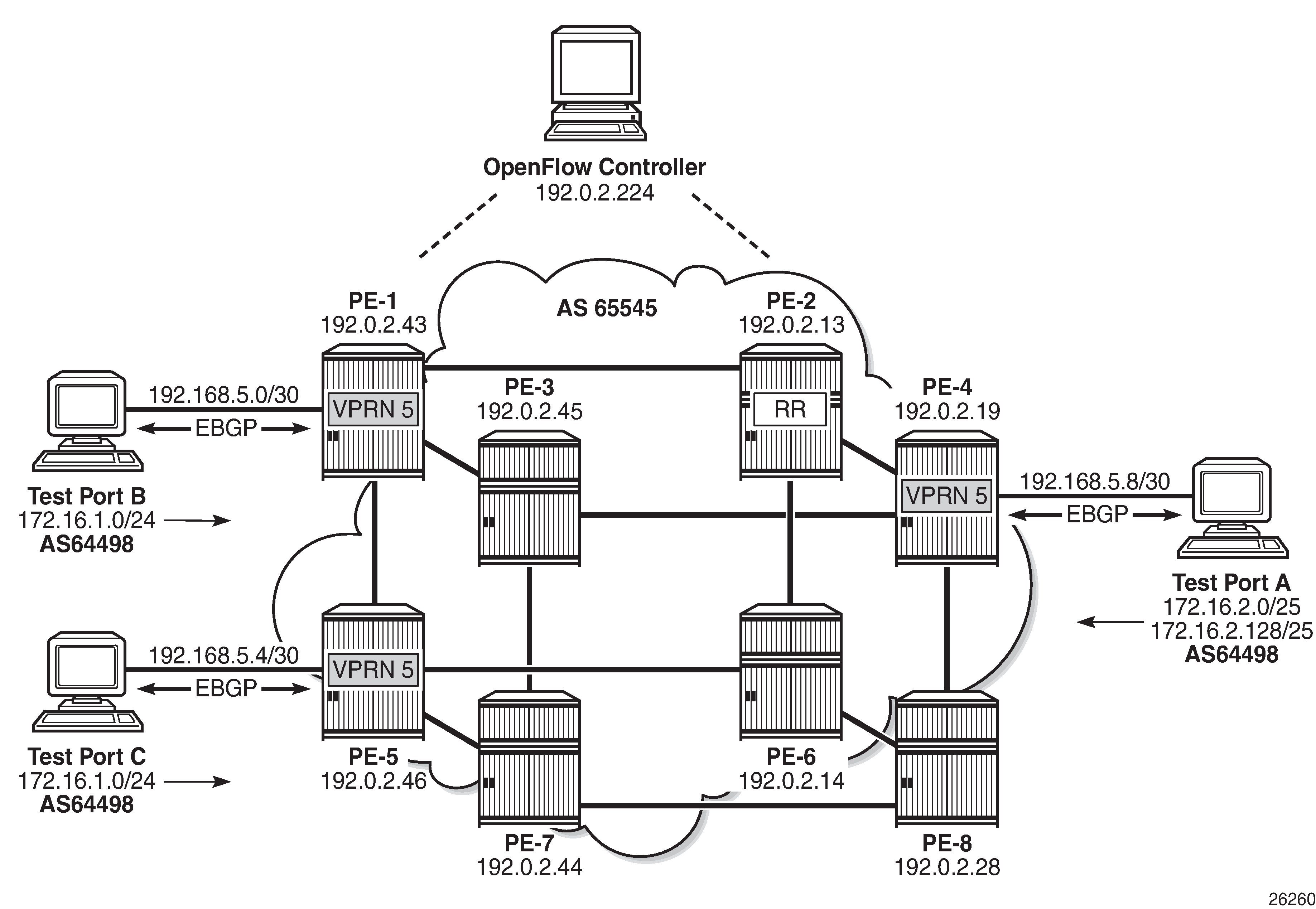
To generate rules within a VPRN routing instance, the example topology is configured as shown in Example Topology for OpenFlow within a Service Routing Context. Test ports A, B, and C belong to VPRN 5. Test ports B and C simulate CE routers in a dual-homed site, advertising prefix 172.16.1.0/24 in EBGP to PE-1 and PE-5, respectively. Test port A simulates a CE router at a different site, advertising prefixes 172.16.2.0/25 and 172.16.2.128/25 in EBGP to PE-4. The PE to CE (WAN) links are also advertised into VPN-IPv4 by the respective PE routers, to provide complete visibility of the VPN.
An IP filter is configured using the embed-filter open-flow command to allow for dynamic embedding of flow entries by an OpenFlow switch instance. In this example, the OpenFlow switch remains as ofs-1. The command also specifies service 5 to make this filter applicable to interfaces within that service instance. Thereafter, this filter can only be deployed in the configured service. An offset is also defined to specify the start point for dynamically created OpenFlow entries and allow them to remain isolated from other dynamic and static filter entries.
configure
    filter
        ip-filter 20 create
            description "OpenFlow Service Filter"
            embed-filter open-flow "ofs-1" service 5 offset 100
        exit
The embed-filter command has the option to configure a service ID or a SAP ID. The former is applicable to embedding filters applied in VPRN or VPLS services. The latter is applicable only to VPLS services. It requires that the embedding filter has the scope of exclusive (as opposed to the default scope of template) and can only be deployed on the SAP specified in the argument.
The filter is applied at PE-4 on the SAP connecting test port A, as follows:
configure
    service
        vprn 5 customer 1 create
            interface "Test-Port-A" create
                address 192.168.5.9/30
                sap 3/1/4:5 create
                    ingress
                        filter ip 20
                    exit
                exit
            exit
As with the example of the base routing context, before any flow entries are initiated from the controller, a single entry with ID 65535 (maximum) is automatically populated in the filter, representing the table-miss entry. As before, when OpenFlow uses filters, it ignores any default-action that may be configured in the filters, so that filters can be chained. However, a table-miss action must exist and this is represented by entry 65535, as follows:
B:PE-4# show filter ip 20
===============================================================================
IP Filter
===============================================================================
Filter Id           : 20                           Applied        : Yes
Scope               : Template                     Def. Action    : Drop
System filter       : Unchained
Radius Ins Pt       : n/a
CrCtl. Ins Pt       : n/a
RadSh. Ins Pt       : n/a
PccRl. Ins Pt       : n/a
Entries             : 0/0/0/1 (Fixed/Radius/Cc/Embedded)
Description         : OpenFlow Service Filter
-------------------------------------------------------------------------------
Filter Match Criteria : IP
-------------------------------------------------------------------------------
Entry               : 65535
Origin              : Inserted by open-flow (no-match-action)
Description         : (Not Specified)
Log Id              : n/a
Src. IP             : 0.0.0.0/0
Src. Port           : n/a
Dest. IP            : 0.0.0.0/0
Dest. Port          : n/a
Protocol            : Undefined                    Dscp           : Undefined
ICMP Type           : Undefined                    ICMP Code      : Undefined
Fragment            : Off                          Src Route Opt  : Off
Sampling            : Off                          Int. Sampling  : On
IP-Option           : 0/0                          Multiple Option: Off
TCP-syn             : Off                          TCP-ack        : Off
Option-pres         : Off
Egress PBR          : Disabled
Primary Action      : Forward
Ing. Matches        : 8193635 pkts (4194988287 bytes)
Egr. Matches        : 0 pkts

===============================================================================
An OpenFlow IP filter, _tmnx_ofs_ofs-1:16, is also automatically created by the system and contains all of the flow entries dynamically created by the OpenFlow switch ofs-1 for service ID 5. This filter acts as a repository for active flow entries specific to that service context and its purpose has been previously described. If a new filter is configured to embed OpenFlow entries for service ID 5, the entries from _tmnx_ofs_ofs-1:16 will be cloned into that new filter.
B:PE-4# show filter ip filter-type openflow
===============================================================================
Openflow IP Filters                                              Total:     2
===============================================================================
Filter-Id                     Description
-------------------------------------------------------------------------------
_tmnx_ofs_ofs-1:15            Filter for OFS 'ofs-1' for grt context
_tmnx_ofs_ofs-1:16            Filter for OFS 'ofs-1' for service [5] context
===============================================================================
OpenFlow Filtering in Action
To validate flow entries initiated by the controller, the following traffic flows are sourced from test port A connected to PE-4:
A UDP-based flow with a source address of 172.16.2.1/25 and a destination address of 172.16.1.1/24 at a rate of 1000 packets/s.
A UDP-based flow with a source address of 172.16.2.129/25 and a destination address of 172.16.1.1/24, again at a rate of 1000 packets/s.
Both test port B and C are advertising the preceding prefixes, which are advertised internally in VPN-IPv4 by PE-1 and PE-5, respectively. At PE-4, the preferred next-hop for 172.16.1.0/24 within VPRN 5 is PE-1 (192.0.2.43), as follows:
B:PE-4# show router 5 route-table 172.16.1.0/24
===============================================================================
Route Table (Service: 5)
===============================================================================
Dest Prefix[Flags]                            Type    Proto     Age        Pref
      Next Hop[Interface Name]                                    Metric
-------------------------------------------------------------------------------
172.16.1.0/24                                 Remote  BGP VPN   01h47m36s  170
       192.0.2.43 (tunneled:RSVP:9)                                 0
-------------------------------------------------------------------------------
No. of Routes: 1
Flags: n = Number of times nexthop is repeated
       B = BGP backup route available
       L = LFA nexthop available
       S = Sticky ECMP requested
===============================================================================
PE-1 is egressing traffic at a rate of 2000 packets/s toward test port B, representing the sum of the two 1000 packets/s test streams, as follows:
B:PE-1# monitor service id 1 sap 5/1/3:10 rate
===============================================================================
Monitor statistics for Service 1 SAP 5/1/3:10
===============================================================================
---snip---
-------------------------------------------------------------------------------
At time t = 22 sec (Mode: Rate)
-------------------------------------------------------------------------------
                        Packets                 Octets                  % Port
                                                                        Util.
Egress Queue 1
For. In/InplusProf    : 0                       7                       ~0.00
For. Out/ExcProf      : 2000                    1023907                 0.08
Dro. In/InplusProf    : 0                       0                       0.00
Dro. Out/ExcProf      : 0                       0                       0.00
An OFPT_FLOW_MOD message containing an OFPFC_ADD command is initiated by the controller and can be viewed using the command in the following output:
B:PE-4# tools dump open-flow of-switch "ofs-1"

===============================================================================
Switch: ofs-1
===============================================================================
Table     : 0                           Flow Pri  : 0
Cookie    : 0x0000000000000000          CookieType: grt
Controller: :::0
Filter Hnd: 0xC300000F0000FFFF
Filter    : _tmnx_ofs_ofs-1:15 entry 65535

In Port   : *
VID       : *                           Outer VID : *
EthType   : *
Src IP    : *
Dst IP    : *
IP Proto  : *                           DSCP      : *
Src Port  : *                           Dst Port  : *
ICMP Type : *                           ICMP Code : *
Label     : *
IPv6ExtHdr: (Not Specified)

Action    : Fall-through

Flow Flags: IPv4/6 [!E] [RO] [DEF]
Up Time   : 0d 05:01:44                 Add TS    : 422384764
Mod TS    : 0                           Stats TS  : 424195136
#Packets  : 27501425                    #Bytes    : 14080300394
-------------------------------------------------------------------------------
Table     : 0                           Flow Pri  : 1535
Cookie    : 0xC000000500000038          CookieType: service 5
Controller: 192.0.2.224:6653
Filter Hnd: 0x830000100000FA00
Filter    : _tmnx_ofs_ofs-1:16 entry 64000

In Port   : *
VID       : *                           Outer VID : *
EthType   : 0x0800
Src IP    : 172.16.2.128/25
Dst IP    : *
IP Proto  : *                           DSCP      : *
Src Port  : *                           Dst Port  : *
ICMP Type : *                           ICMP Code : *
Label     : *

Action    : Forward On Nhop(Indirect)
            Nhop: 192.168.5.6

Flow Flags: IPv4 [FR]
Up Time   : 0d 00:00:44                 Add TS    : 424190707
Mod TS    : 0                           Stats TS  : 424195137
#Packets  : 44301                       #Bytes    : 22682112
-------------------------------------------------------------------------------
Number of flows: 2
===============================================================================
The first flow entry with cookie value 0x0000000000000000 is the table-miss entry with a fall-through or forward action. The second entry with cookie value 0xC000000500000038 contains the new flow entry. The high-order bits of the cookie are set to 0xC (or 1100), which (as shown in Table 2) means that this represents a flow entry that is used by filters used within a service instance. Bits 59 to 32 encode the service instance, which in this case is 5.
The filter used by this second flow entry is _tmnx_ofs_ofs-1:16, which is the system-created OpenFlow filter for OpenFlow switch ofs-1, and contains all active flows entries initiated by that switch for service ID 5. Any filters embedding OpenFlow flow entries from ofs-1 in service ID 5 will clone all of the entries contained in _tmnx_ofs_ofs-1:16. In this example, the entries in _tmnx_ofs_ofs-1:16 are cloned into IP filter 20. IP filter 20 will also include ingress packets/bytes matched for each entry.
The priority field indicates a value of 1535 and, as previously described, determines the order in which flow entries are processed, using the formula [65535 - flow_priority + embedding offset].
The OpenFlow Match fields specify an Ethertype of IPv4 (0x0800) for source prefix 172.16.2.128/25, and are mapped directly into filter entry match criteria. The OpenFlow instruction type is Write_Actions (OFPIT_WRITE_ACTIONS) in order to create the new flow entry, and has an action type of Forward to Next-Hop IP Address. Because OpenFlow has no standard action type of Forward to Next-Hop IP Address, an Experimenter (OFPAT_EXPERIMENTER) is used for this purpose, which encompasses the use of both direct and indirect next-hops. In this example, an indirect next-hop of 192.168.5.6 is used.
The preferred next-hop for traffic destined to prefix 172.16.1.0/24 is PE-1. The indirect next-hop address of 192.168.5.6 represents the (simulated) CE WAN address of test port C, and is known in the routing table of VPRN 5 with a next-hop of PE-5 (192.0.2.46), as follows:
B:PE-4# show router 5 route-table 192.168.5.6
===============================================================================
Route Table (Service: 5)
===============================================================================
Dest Prefix[Flags]                            Type    Proto     Age        Pref
      Next Hop[Interface Name]                                    Metric
-------------------------------------------------------------------------------
192.168.5.4/30                                Remote  BGP VPN   19h19m22s  170
       192.0.2.46 (tunneled:RSVP:10)                                0
-------------------------------------------------------------------------------
No. of Routes: 1
Flags: n = Number of times nexthop is repeated
       B = BGP backup route available
       L = LFA nexthop available
       S = Sticky ECMP requested
===============================================================================
The dynamic OpenFlow flow entry redirecting traffic with a source address of 172.16.2.128/25 is now in place as entry 64000 within IP filter _tmnx_ofs_ofs-1:16, and cloned into IP filter 20. The effect of this OpenFlow flow entry on the two test streams is as follows:
Traffic sourced from prefix 172.16.2.0/25 to prefix 172.16.1.0/24 is routed in accordance with the VPRN 5 routing table, with a next-hop of PE-1.
Traffic sourced from prefix 172.16.2.128/25 to prefix 172.16.1.0/24 is subject to policy-based routing and, rather than being routed directly toward the destination prefix known via PE-1, is forwarded to an indirect next-hop of 192.168.5.6, known via PE-5.
This is validated in the following two outputs, which show a monitor command run against PE-1's SAP toward test port B and PE-5's SAP toward test port C. The outputs show that each SAP is egressing 1000 packets/s:
B:PE-1# monitor service id 5 sap 5/1/3:5 rate
===============================================================================
Monitor statistics for Service 5 SAP 5/1/3:5
===============================================================================
---snip---
                        Packets                 Octets                  % Port
                                                                        Util.
Egress Queue 1
For. In/InplusProf    : 0                       8                       ~0.00
For. Out/ExcProf      : 1000                    512000                  0.04
Dro. In/InplusProf    : 0                       0                       0.00
Dro. Out/ExcProf      : 0                       0                       0.00
A:PE-5# monitor service id 5 sap lag-1:5 rate
===============================================================================
Monitor statistics for Service 5 SAP lag-1:5
===============================================================================
---snip---
                        Packets                 Octets                  % Port
                                                                        Util.
Egress Queue 1
For. In/InplusProf    : 0                       0                       0.00
For. Out/ExcProf      : 1000                    512000                  0.04
Dro. In/InplusProf    : 0                       0                       0.00
Dro. Out/ExcProf      : 0                       0                       0.00
As previously described, dynamic flow entries will remain in place as filter entries until removed by the controller or the OpenFlow switch instance is put in a shutdown state.
Supported Redirect Actions
Table 4 lists the redirect actions supported in SR OS together with the applicability and associated action types. Experimenter encodings are described in user guides. Unless otherwise stated, all instruction types are WRITE_ACTION/APPLY_ACTION.
Action |
Applicability |
Action Type |
Remarks |
|---|---|---|---|
Redirect to IP Next-Hop |
IPv4/IPv6 traffic ingressing an IP interface |
OFPAT_EXPERIMENTER (ALU_AXN_REDIRECT_TO_NEXTHOP) |
Next-hop can be direct or indirect |
Redirect to Routing Context (GRT or VRF) |
OFPAT_OUTPUT <logical_port> <logical_port> encoding: Bits 31-28=0100, bits 27-24=0001, bits 23-0=VPRN service ID or 0 for GRT |
||
Redirect to Next-Hop and VRF/GRT Routing Context |
Action 1: OFPAT_EXPERIMENTER (ALU_AXN_REDIRECT_TO_NEXTHOP) |
Next-hop must be indirect |
|
Action 2: OFPAT_OUTPUT <logical_port> <logical_port> encoding: Bits 31-28=0100, bits 27-24=0001, bits 23-0=VPRN service ID or 0 for GRT |
|||
Redirect to LSP |
OFPAT_OUTPUT <logical_port> <logical_port> encoding: Bits 31-28=0100, bits 27-24=0000, bits 23-0=RSVP-TE Tunnel ID |
||
Redirect to SAP |
Traffic ingressing a VPLS interface |
Action 1: OFPAT_OUTPUT <port> <port> encoding: OXM_OF_IN_PORT: TmnxPortID for Ethernet port or LAG |
TmnxPortId encoding in TIMETRA-CHASSIS-MIB (port) or LAG TIMETRA-TC-MIB (LAG) |
Action 2: OFPAT_SET_FIELD <vlan_encoding> VLAN encoding: OXM_OF_VLAN_ID (null, dot1Q, or inner QinQ tag) Optional EXPERIMENTER OFL_OUT_VLAN_ID (outer QinQ tag) |
|||
Redirect to SDP |
OFPAT_EXPERIMENTER (ALU_AXN_REDIRECT_TO_SDP) |
Possible to match against entire SAP using OXM_OF_IN_PORT encoding TmnxPortID, OXM_OF_VLAN_ID (null tag, dot1Q tag, inner Q-in-Q tag) and optional EXPERIMENTER OFL_OUT_VLAN_ID (outer Q-in-Q tag) |
Resource Consumption
Dynamic OpenFlow flow entries are embedded in filters as filter entries, and as such, consume CAM entries in the same way as statically configured filter entries and/or other dynamic filter entries, such as those created by BGP FlowSpec or RADIUS. When a flow entry is created and dynamically embedded as a filter entry, it will consume one or more ingress ACL/QoS entries from the line card to which the filter is attached. If a flow entry is embedded in multiple filters, an ingress ACL/QoS entry will be consumed for each filter. If a flow entry is embedded in a single filter with a default scope of template, and this filter is attached to multiple SAPs on the same line card, only a single entry is consumed.
As with conventional ACL resource consumption, a standard four- or five-tuple match will consume a single entry. Defining a range of ports, for example, will consume multiple entries, as follows:
B:PE-4# tools dump system-resources 3
Resource Manager info at 049 d 12/01/16 09:10:18.148:
Hardware Resource Usage for Slot #3, CardType imm12-10gb-sf+, Cmplx #0:
                                 |   Total   | Allocated |    Free
  -------------------------------|-----------|-----------|------------
---snip---
         Ingress ACL/QoS Entries |      65536|          5|      65531
---snip---
Debugging
A number of OpenFlow debug commands are available. For troubleshooting and interoperability purposes, detailed packet-level debug commands are available for all OpenFlow message types. Also, the ability to debug OpenFlow switch errors is useful. An example is provided in the following output:
debug
    open-flow
        of-switch "ofs-1"
            error
            packet flow-mod detail
        exit
    exit
exit
Conclusion
OpenFlow has a number of use-cases in the WAN. The dynamic insertion of flow entries from a controller can be used for flow placement in an SDN environment implementing some business logic. Equally, it could be used to implement security measures, or off-ramping of traffic to a DDoS scrubbing center.
This chapter described how to configure and deploy Hybrid OpenFlow in SR OS. It described how to configure the OpenFlow switch, and how filter entries are dynamically embedded in GRT filters and service filters. These examples are intended to provide an overview of functionality.