Bi-Directional Forwarding Detection
Topics in this chapter include:
Applicability
This chapter was originally written for SR OS Release 8.0.R4. The CLI in the current edition corresponds to SR OS Release 23.3.R1.
Overview
Bi-directional forwarding detection (BFD) is a lightweight protocol that provides rapid path failure detection between two systems. It has been published as a series of RFCs: RFC 5880, RFC 5881, RFC 5882, RFC 5883, and RFC 5884.
If a system running BFD stops receiving BFD messages on an interface, it will determine that there has been a failure in the path and notify other protocols associated with the interface. BFD is useful in situations where two nodes are interconnected through either an optical dense wavelength division multiplexing (DWDM) or Ethernet network. In both cases, the physical network has numerous extra devices which are not part of the Layer 3 network and therefore, the Layer 3 nodes are incapable of detecting failures which occur in the physical network on spans to which the Layer 3 devices are not directly connected.
BFD protocol provides rapid link continuity checking between network devices, and the state of BFD can be propagated to IP routing protocols to drastically reduce convergence time in cases where a physical network error occurs in a transport network.
RFC 5880 defines two modes of operation for BFD:
Asynchronous mode (supported) — Uses periodic BFD control messages to test the path between systems
Demand mode (not supported)
In addition to the two operational modes, an echo function is defined. SR OS routers only support response sending, which is looping back received BFD messages to the original sender.
BFD is running between two peers and supported for scenarios such as:
BFD for IS-IS
BFD for OSPF
BFD for PIM
BFD for static routes
-
BFD for RSVP
-
BFD for I-LDP
-
BFD for T-LDP
-
BFD for MPLS-TP
BFD for OSPF CE-PE adjacencies
-
BFD for VRRP
-
BFD for SRRP
-
BFD for IPSec
Most of these BFD scenarios are described in this chapter.
Configuration
BFD packets are processed both locally on the IOM CPU and centrally on the CPM.
The CPM is able to centrally generate the BFD packets at a subsecond interval as low as 10 ms. The BFD state machine is implemented in software. BFD packet generation can be selectively delegated to CPM hardware as needed. This is applicable when subsecond operations or exceeding the IOM scaling limits is required.
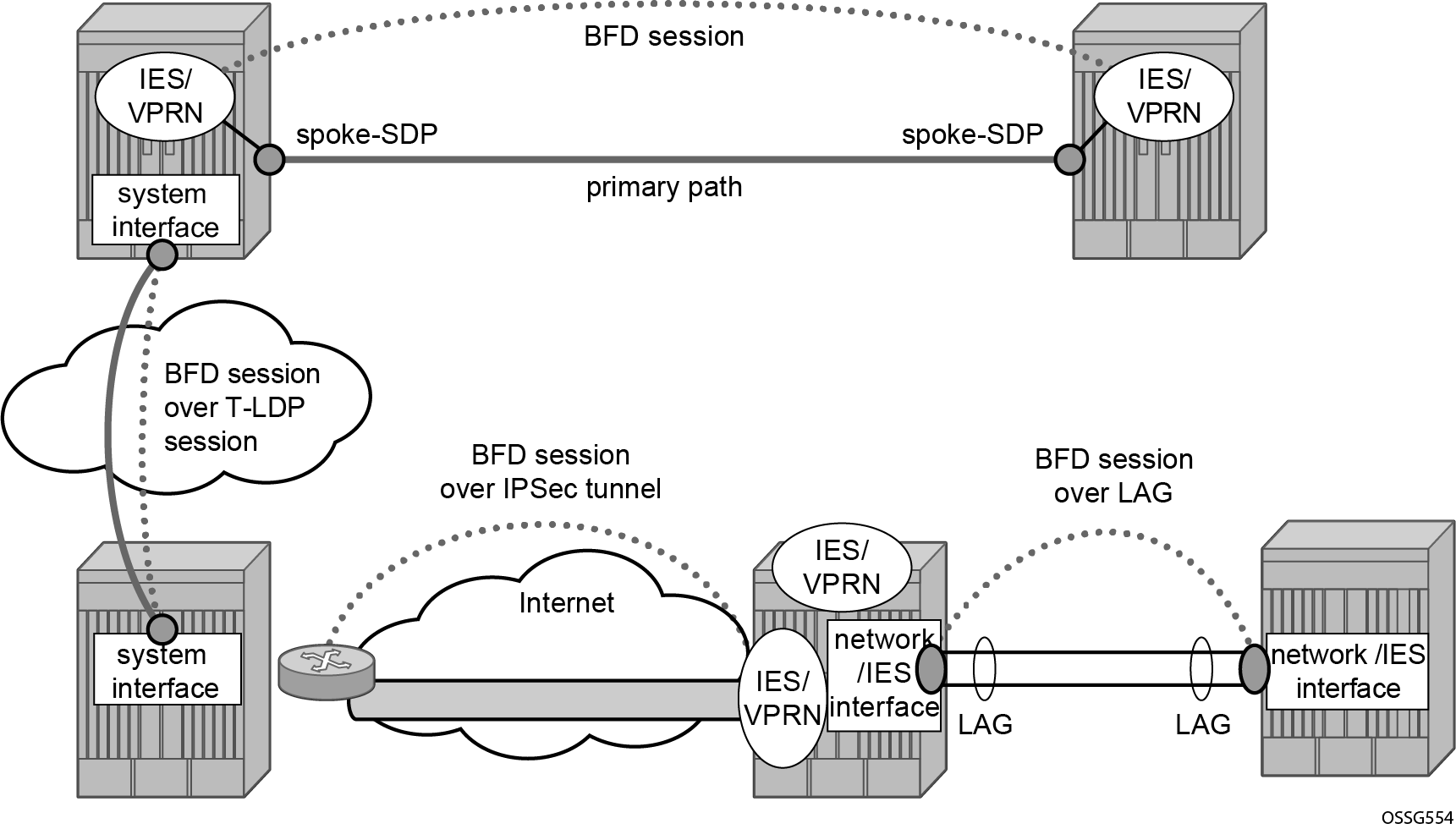
The following applications require BFD to run centrally on the SF/CPM and a centralized session will be created independently of the type explicitly declared by the user:
BFD for IES/VPRN over spoke SDP
BFD for LAG and VSM interfaces
Protocol associations using loopback and system interfaces (for example, BFD for T-LDP)
BFD for IPSec sessions
BFD sessions associated with multi-hop peering (BGP)
BFD centralized sessions shows the most relevant scenarios where centralized BFD sessions are used.
On the other end, when the two peers are directly connected, the BFD session is local by default, but the user can choose what session type (local or centralized) to implement.
As general rule, the following steps are required to configure and enable a BFD session when peers are directly connected:
configure BFD parameters on the peering interfaces
check that the Layer 3 protocol, that is to be bound to BFD, is up and running
enable BFD under the Layer 3 protocol interface.
Because most of the following procedures share the same first step, it is described only once in the next section and then referred to in subsequent sections.
BFD base parameter configuration and troubleshooting
The reference topology for the generic configuration of BFD over two local peers is shown in BFD interface configuration.
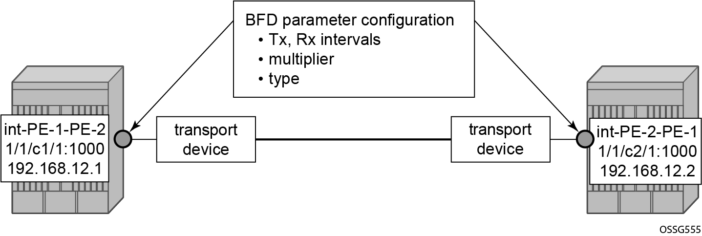
The user needs to configure base level BFD on interfaces between the peers PE-1 and PE-2. In this example, the transmit interval is 100 ms, the receive interval is 100 ms, and the multiplier is 3:
# on PE-1:
configure
    router Base
        interface "int-PE-1-PE-2"
            address 192.168.12.1/30
            port 1/1/c1/1:1000
            bfd 100 receive 100 multiplier 3
            no shutdown
        exit
# on PE-2:
configure
    router Base
        interface "int-PE-2-PE-1"
            address 192.168.12.2/30
            port 1/1/c2/1:1000
            bfd 100 receive 100 multiplier 3
            no shutdown
        exit
The following show commands are used to verify the BFD configuration on the router interfaces on PE-1 and PE-2.
On PE-1:
*A:PE-1# show router bfd interface

===============================================================================
BFD Interface
===============================================================================
Interface name                     Tx Interval    Rx Interval    Multiplier
-------------------------------------------------------------------------------
int-PE-1-PE-2                      100            100            3
-------------------------------------------------------------------------------
No. of BFD Interfaces: 1
===============================================================================
On PE-2:
*A:PE-2# show router bfd interface

===============================================================================
BFD Interface
===============================================================================
Interface name                     Tx Interval    Rx Interval    Multiplier
-------------------------------------------------------------------------------
int-PE-2-PE-1                      100            100            3
-------------------------------------------------------------------------------
No. of BFD Interfaces: 1
===============================================================================
The configurable BFD parameters are the following:
*A:PE-1>config>router>if# bfd ?
  - bfd <transmit-interval> [receive <receive-interval>] [multiplier <multiplier>] [echo-receive
    <echo-interval>] [type <type>]
  - no bfd

 <transmit-interval>  : [10..100000] in milliseconds
 <receive-interval>   : [10..100000] in milliseconds
 <multiplier>         : [1..20]
 <echo-interval>      : [100..100000] in milliseconds
 <type>               : cpm-np - use CPM network processor
It is possible to force the BFD session to be centrally managed by the CPM hardware: type cpm-np.
Regarding the echo function, it is possible to set the minimum echo receive interval, in milliseconds, for the BFD session. The default value is 100 ms.
The base BFD configuration on the router interfaces is not sufficient for a BGP session to come up:
*A:PE-1# show router bfd session

===============================================================================
Legend:
  Session Id = Interface Name | LSP Name | Prefix | RSVP Sess Name | Service Id
  wp = Working path   pp = Protecting path
===============================================================================
BFD Session
===============================================================================
Session Id                                        State      Tx Pkts    Rx Pkts
  Rem Addr/Info/SdpId:VcId                      Multipl     Tx Intvl   Rx Intvl
  Protocols                                        Type     LAG Port     LAG ID
  Loc Addr                                                             LAG name
-------------------------------------------------------------------------------
No Matching Entries Found
===============================================================================
Configuring the BFD parameters on the interface does not enable BFD sessions. BFD can be enabled afterward, for instance, in IS-IS.
If a BFD session is active on the interface, an attempt to modify the BFD type triggers the following error message:
*A:PE-1>config>router>if# bfd 10 receive 10 multiplier 3 type cpm-np
INFO: BFD #1001 Inconsistent value - BFD sessions active on this interface.
Cannot change BfdType on this interface
Forcing a centralized session in the case of directly connected peers can be useful when:
lower Tx and Rx intervals are desired (down to 10 ms instead of 100 ms supported by local sessions)
no more local (IOM) sessions are available
the maximum limit of 500 packets per second per IOM has been reached
The instructions illustrated in following paragraphs are required to complete the configuration and enable BFD.
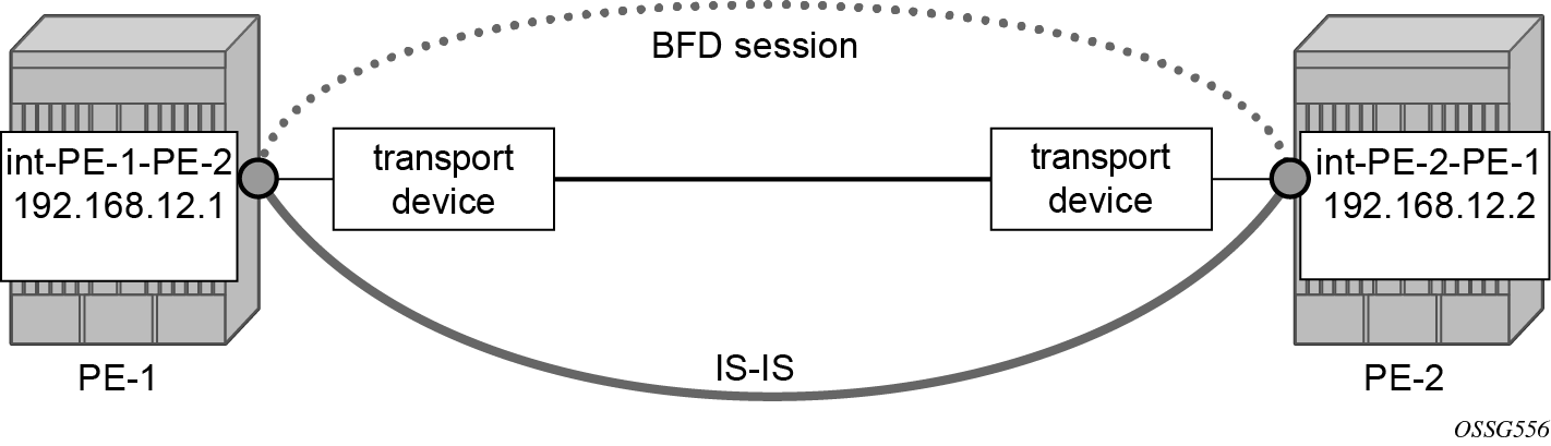
BFD for IS-IS
The goal of this section is to configure BFD on a network interlink between two SR OS nodes that are IS-IS peers. The topology used is shown in BFD for ISIS.
For the base BFD configuration, see the BFD base parameter configuration and troubleshooting section.
On PE-1, BFD is applied to the IS-IS interface between PE-1 and PE-2:
# on PE-1:
configure
    router Base
        isis 0
            interface "int-PE-1-PE-2"
                bfd-enable ipv4
            exit
When BFD is only applied on PE-1 and not on PE-2, the BFD session on PE-1 remains down, as follows:
*A:PE-1# show router bfd session

===============================================================================
Legend:
  Session Id = Interface Name | LSP Name | Prefix | RSVP Sess Name | Service Id
  wp = Working path   pp = Protecting path
===============================================================================
BFD Session
===============================================================================
Session Id                                        State      Tx Pkts    Rx Pkts
  Rem Addr/Info/SdpId:VcId                      Multipl     Tx Intvl   Rx Intvl
  Protocols                                        Type     LAG Port     LAG ID
  Loc Addr                                                             LAG name
-------------------------------------------------------------------------------
int-PE-1-PE-2                                      Down           14          0
  192.168.12.2                                        3         1000        100
  isis                                              iom          N/A        N/A
  192.168.12.1
-------------------------------------------------------------------------------
No. of BFD sessions: 1
===============================================================================
On PE-2, BFD is enabled on the interface to PE-1, as follows:
# on PE-2:
configure
    router Base
        isis 0
            interface "int-PE-2-PE-1"
                bfd-enable ipv4
            exit
The following command verifies that the local IOM BFD session is operational between PE-1 and PE-2.
On PE-1:
*A:PE-1# show router bfd session

===============================================================================
Legend:
  Session Id = Interface Name | LSP Name | Prefix | RSVP Sess Name | Service Id
  wp = Working path   pp = Protecting path
===============================================================================
BFD Session
===============================================================================
Session Id                                        State      Tx Pkts    Rx Pkts
  Rem Addr/Info/SdpId:VcId                      Multipl     Tx Intvl   Rx Intvl
  Protocols                                        Type     LAG Port     LAG ID
  Loc Addr                                                             LAG name
-------------------------------------------------------------------------------
int-PE-1-PE-2                                        Up          231        179
  192.168.12.2                                        3          100        100
  isis                                              iom          N/A        N/A
  192.168.12.1
-------------------------------------------------------------------------------
No. of BFD sessions: 1
===============================================================================
On PE-2:
*A:PE-2# show router bfd session

===============================================================================
Legend:
  Session Id = Interface Name | LSP Name | Prefix | RSVP Sess Name | Service Id
  wp = Working path   pp = Protecting path
===============================================================================
BFD Session
===============================================================================
Session Id                                        State      Tx Pkts    Rx Pkts
  Rem Addr/Info/SdpId:VcId                      Multipl     Tx Intvl   Rx Intvl
  Protocols                                        Type     LAG Port     LAG ID
  Loc Addr                                                             LAG name
-------------------------------------------------------------------------------
int-PE-2-PE-1                                        Up          152        151
  192.168.12.1                                        3          100        100
  isis                                              iom          N/A        N/A
  192.168.12.2
-------------------------------------------------------------------------------
No. of BFD sessions: 1
===============================================================================
If the command shows that the BFD session is down, troubleshoot it by first checking that the protocol that is bound to it is up: for instance, check the IS-IS adjacency, as follows:
*A:PE-1# show router isis adjacency "int-PE-1-PE-2"

===============================================================================
Rtr Base ISIS Instance 0 Adjacency
===============================================================================
System ID                Usage State Hold Interface                     MT-ID
-------------------------------------------------------------------------------
PE-2                     L1L2  Up    22   int-PE-1-PE-2                 0
-------------------------------------------------------------------------------
Adjacencies : 1
===============================================================================
If the IS-IS adjacency is up, then check whether a BFD resource limit has been reached (maximum number of local/centralized sessions or maximum number of packets per second per IOM).
If the overloaded limit is the maximum supported number of sessions, the cause is shown in log 99 (maxSessionsPerSlot).
In this case, when one of the running sessions is manually removed or goes down, then the additional configured session will come up. If the IOM limit is reached, it is possible to bring up the session by changing the session type to centralized.
To check if the IOM CPU is able to start more local BFD sessions, execute a show router bfd session summary command:
*A:PE-1# show router bfd session summary

=============================
BFD Session Summary
=============================
Termination    Session Count
-----------------------------
central                    0
cpm-np                     0
iom, slot 1                1
iom, slot 2                0
iom, slot 3                0
iom, slot 4                0
iom, slot 5                0
iom, slot 6                0
Total                      1
=============================
The show router bfd session src <ip-address> detail command can help debugging the BFD session. The sent and received counters are not supported for cpm-np type sessions.
*A:PE-1# show router bfd session src 192.168.12.1 detail

===============================================================================
BFD Session
===============================================================================
Remote Address : 192.168.12.2
Local Address  : 192.168.12.1
Admin State    : Up                       Oper State       : Up
Protocols      : isis
Rx Interval    : 100                      Tx Interval      : 100
Multiplier     : 3                        Echo Interval    : 0
Recd Msgs      : 1253                     Sent Msgs        : 1305
Up Time        : 0d 00:01:38              Up Transitions   : 1
Last Down Time : 0d 00:00:46              Down Transitions : 0
                                          Version Mismatch : 0

Forwarding Information

Local Discr    : 1                        Local State      : Up
Local Diag     : 0 (None)                 Local Mode       : Async
Local Min Tx   : 100                      Local Mult       : 3
Last Sent      : 04/06/2023 15:03:04      Local Min Rx     : 100
Type           : iom
Remote Discr   : 1                        Remote State     : Up
Remote Diag    : 0 (None)                 Remote Mode      : Async
Remote Min Tx  : 100                      Remote Mult      : 3
Remote C-flag  : 1
Last Recv      : 04/06/2023 15:03:04      Remote Min Rx    : 100
===============================================================================
===============================================================================
BFD for OSPF
The goal of this section is to configure BFD on a network interlink between two SR OS nodes that are OSPF peers. BFD for OSPFshows the topology for this scenario.
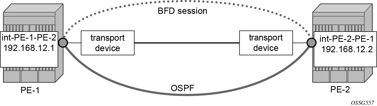
The base BFD configuration is described in the section BFD base parameter configuration and troubleshooting.
In this section, BFD is applied on the OSPF interfaces, as follows:
# on PE-1:
configure
    router Base
        ospf 0
            traffic-engineering
            area 0.0.0.0
                interface "system"
                    no shutdown
                exit
                interface "int-PE-1-PE-2"
                    interface-type point-to-point
                    bfd-enable
                    no shutdown
                exit
            exit
            no shutdown
# on PE-2:
configure
    router Base
        ospf 0
            traffic-engineering
            area 0.0.0.0
                interface "system"
                    no shutdown
                exit
                interface "int-PE-2-PE-1"
                    interface-type point-to-point
                    bfd-enable
                    no shutdown
                exit
            exit
            no shutdown
The following commands verify that the BFD session for OSPF is operational between PE-1 and PE-2.
On PE-1:
*A:PE-1# show router bfd session

===============================================================================
Legend:
  Session Id = Interface Name | LSP Name | Prefix | RSVP Sess Name | Service Id
  wp = Working path   pp = Protecting path
===============================================================================
BFD Session
===============================================================================
Session Id                                        State      Tx Pkts    Rx Pkts
  Rem Addr/Info/SdpId:VcId                      Multipl     Tx Intvl   Rx Intvl
  Protocols                                        Type     LAG Port     LAG ID
  Loc Addr                                                             LAG name
-------------------------------------------------------------------------------
int-PE-1-PE-2                                        Up          102        101
  192.168.12.2                                        3          100        100
  ospf2                                             iom          N/A        N/A
  192.168.12.1
-------------------------------------------------------------------------------
No. of BFD sessions: 1
===============================================================================
On PE-2:
*A:PE-2# show router bfd session

===============================================================================
Legend:
  Session Id = Interface Name | LSP Name | Prefix | RSVP Sess Name | Service Id
  wp = Working path   pp = Protecting path
===============================================================================
BFD Session
===============================================================================
Session Id                                        State      Tx Pkts    Rx Pkts
  Rem Addr/Info/SdpId:VcId                      Multipl     Tx Intvl   Rx Intvl
  Protocols                                        Type     LAG Port     LAG ID
  Loc Addr                                                             LAG name
-------------------------------------------------------------------------------
int-PE-2-PE-1                                        Up           69         69
  192.168.12.1                                        3          100        100
  ospf2                                             iom          N/A        N/A
  192.168.12.2
-------------------------------------------------------------------------------
No. of BFD sessions: 1
===============================================================================
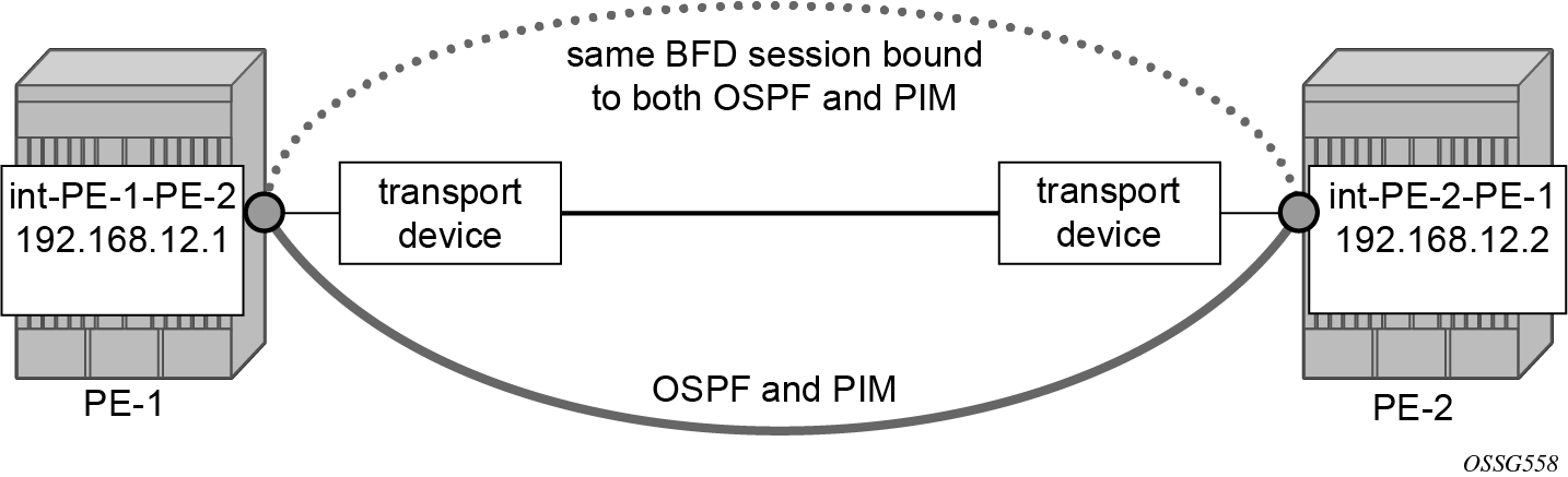
BFD for PIM
The PIM implementation uses an interior gateway protocol (IGP) in order to determine its reverse path forwarding (RPF) tree, so the BFD configuration to support PIM requires the BFD configuration of both the IGP protocol and the PIM protocol. In this example, the IGP protocol is OSPF and that the initial configuration is as described in the section BFD for OSPF.
BFD for OSPF and PIM shows the topology. BFD is configured and enabled for PIM on the same interfaces that were previously configured with BFD for OSPF.
The following commands enable BFD on the PIM interfaces on PE-1 and PE-2.
# on PE-1
configure
    router Base
        pim
            interface "int-PE-1-PE-2"
                bfd-enable
            exit
# on PE-2:
configure
    router Base
        pim
            interface "int-PE-2-PE-1"
                bfd-enable
            exit
The following commands show that the BFD session is operational for OSPF and PIM between PE-1 and PE-2.
*A:PE-1# show router bfd session

===============================================================================
Legend:
  Session Id = Interface Name | LSP Name | Prefix | RSVP Sess Name | Service Id
  wp = Working path   pp = Protecting path
===============================================================================
BFD Session
===============================================================================
Session Id                                        State      Tx Pkts    Rx Pkts
  Rem Addr/Info/SdpId:VcId                      Multipl     Tx Intvl   Rx Intvl
  Protocols                                        Type     LAG Port     LAG ID
  Loc Addr                                                             LAG name
-------------------------------------------------------------------------------
int-PE-1-PE-2                                        Up          764        765
  192.168.12.2                                        3          100        100
  ospf2 pim                                         iom          N/A        N/A
  192.168.12.1
-------------------------------------------------------------------------------
No. of BFD sessions: 1
===============================================================================
*A:PE-2# show router bfd session

===============================================================================
Legend:
  Session Id = Interface Name | LSP Name | Prefix | RSVP Sess Name | Service Id
  wp = Working path   pp = Protecting path
===============================================================================
BFD Session
===============================================================================
Session Id                                        State      Tx Pkts    Rx Pkts
  Rem Addr/Info/SdpId:VcId                      Multipl     Tx Intvl   Rx Intvl
  Protocols                                        Type     LAG Port     LAG ID
  Loc Addr                                                             LAG name
-------------------------------------------------------------------------------
int-PE-2-PE-1                                        Up          734        732
  192.168.12.1                                        3          100        100
  ospf2 pim                                         iom          N/A        N/A
  192.168.12.2
-------------------------------------------------------------------------------
No. of BFD sessions: 1
===============================================================================
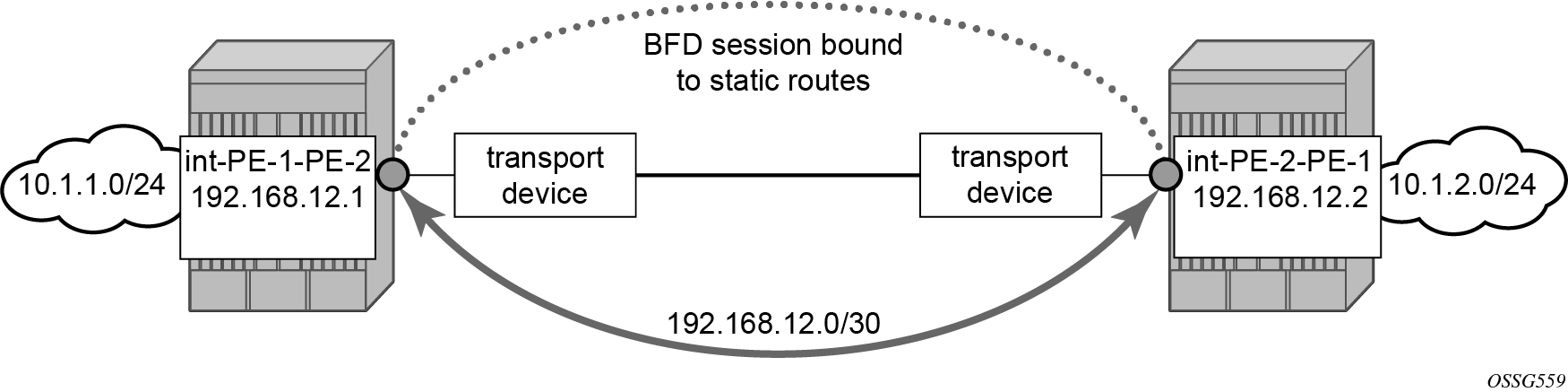
BFD for static routes
In this section, BFD is applied to static routes between PE-1 and PE-2. BFD for static routes shows the topology.
The base level BFD is already configured on PE-1 and PE-2, as described in the BFD base parameter configuration and troubleshooting section.
The following commands configure static routes toward the remote networks in PE-1 and PE-2 using the BFD interfaces as next hop. BFD is enabled on the the next hop interfaces.
# on PE-1:
configure
    router Base
        static-route-entry 10.1.2.0/24
            next-hop 192.168.12.2
                bfd-enable
                no shutdown
            exit
# on PE-2:
configure
    router Base
        static-route-entry 10.1.1.0/24
            next-hop 192.168.12.1
                bfd-enable
                no shutdown
            exit
The following commands show the static routes populated in the routing tables on PE-1 and PE-2.
*A:PE-1# show router route-table protocol static

===============================================================================
Route Table (Router: Base)
===============================================================================
Dest Prefix[Flags]                            Type    Proto     Age        Pref
      Next Hop[Interface Name]                                    Metric
-------------------------------------------------------------------------------
10.1.2.0/24                                   Remote  Static    00h00m04s  5
       192.168.12.2                                                 1
-------------------------------------------------------------------------------
No. of Routes: 1
Flags: n = Number of times nexthop is repeated
       B = BGP backup route available
       L = LFA nexthop available
       S = Sticky ECMP requested
===============================================================================
*A:PE-2# show router route-table protocol static

===============================================================================
Route Table (Router: Base)
===============================================================================
Dest Prefix[Flags]                            Type    Proto     Age        Pref
      Next Hop[Interface Name]                                    Metric
-------------------------------------------------------------------------------
10.1.1.0/24                                   Remote  Static    00h00m03s  5
       192.168.12.1                                                 1
-------------------------------------------------------------------------------
No. of Routes: 1
Flags: n = Number of times nexthop is repeated
       B = BGP backup route available
       L = LFA nexthop available
       S = Sticky ECMP requested
===============================================================================
The following commands show the BFD session status on PE-1 and PE-2.
*A:PE-1# show router bfd session

===============================================================================
Legend:
  Session Id = Interface Name | LSP Name | Prefix | RSVP Sess Name | Service Id
  wp = Working path   pp = Protecting path
===============================================================================
BFD Session
===============================================================================
Session Id                                        State      Tx Pkts    Rx Pkts
  Rem Addr/Info/SdpId:VcId                      Multipl     Tx Intvl   Rx Intvl
  Protocols                                        Type     LAG Port     LAG ID
  Loc Addr                                                             LAG name
-------------------------------------------------------------------------------
int-PE-1-PE-2                                        Up          431        427
  192.168.12.2                                        3          100        100
  static                                            iom          N/A        N/A
  192.168.12.1
-------------------------------------------------------------------------------
No. of BFD sessions: 1
===============================================================================
*A:PE-2# show router bfd session

===============================================================================
Legend:
  Session Id = Interface Name | LSP Name | Prefix | RSVP Sess Name | Service Id
  wp = Working path   pp = Protecting path
===============================================================================
BFD Session
===============================================================================
Session Id                                        State      Tx Pkts    Rx Pkts
  Rem Addr/Info/SdpId:VcId                      Multipl     Tx Intvl   Rx Intvl
  Protocols                                        Type     LAG Port     LAG ID
  Loc Addr                                                             LAG name
-------------------------------------------------------------------------------
int-PE-2-PE-1                                        Up          399        398
  192.168.12.1                                        3          100        100
  static                                            iom          N/A        N/A
  192.168.12.2
-------------------------------------------------------------------------------
No. of BFD sessions: 1
===============================================================================
BFD for IES
The goal of this section is to configure BFD for an IES service over a spoke SDP.
The IES service is configured on PE-1 and PE-2, and their interfaces are connected by spoke SDPs. BFD for IES over spoke SDP shows the topology.
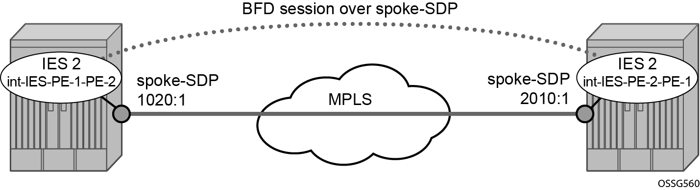
In this scenario, BFD is run between the IES interfaces independent of the SDP or LSP paths.
The following commands on PE-1 and PE-2 configure an IES service and add the IES interfaces to the OSPF area domain. BFD is not configured yet.
# on PE-1:
configure
    service
        sdp 1020 mpls create
            far-end 192.0.2.2
            sr-isis
            keep-alive
                shutdown
            exit
            no shutdown
        exit
        ies 2 name "IES-2" customer 1 create
            interface "int-IES-PE-1-PE-2" create
                address 192.168.12.5/30
                spoke-sdp 1020:1 create
                exit
            exit
            no shutdown
        exit
    exit
    router Base
        ospf 0
            area 0.0.0.0
                interface "int-IES-PE-1-PE-2"
                exit
            exit
        exit
# on PE-2:
configure
    service
        sdp 2010 mpls create
            far-end 192.0.2.1
            sr-isis
            keep-alive
                shutdown
            exit
            no shutdown
        exit
        ies 2 name "IES-2" customer 1 create
            interface "int-IES-PE-2-PE-1" create
                address 192.168.12.6/30
                spoke-sdp 2010:1 create
                exit
            exit
            no shutdown
        exit
    exit
    router Base
        ospf 0
            area 0.0.0.0
                interface "int-IES-PE-2-PE-1"
                exit
            exit
        exit
The following commands verify that OSPF and the services are up on both routers.
On PE-1:
*A:PE-1# show service id 2 base

===============================================================================
Service Basic Information
===============================================================================
Service Id        : 2                   Vpn Id            : 0
Service Type      : IES
MACSec enabled    : no
Name              : IES-2
Description       : (Not Specified)
Customer Id       : 1                   Creation Origin   : manual
Last Status Change: 04/06/2023 15:08:19
Last Mgmt Change  : 04/06/2023 15:08:05
Admin State       : Up                  Oper State        : Up
SAP Count         : 0                   SDP Bind Count    : 1

-------------------------------------------------------------------------------
Service Access & Destination Points
-------------------------------------------------------------------------------
Identifier                               Type         AdmMTU  OprMTU  Adm  Opr
-------------------------------------------------------------------------------
sdp:1020:1 S(192.0.2.2)                  Spok         0       8910    Up   Up
===============================================================================
*A:PE-1# show router ospf neighbor

===============================================================================
Rtr Base OSPFv2 Instance 0 Neighbors
===============================================================================
Interface-Name                   Rtr Id          State      Pri  RetxQ   TTL
   Area-Id
-------------------------------------------------------------------------------
int-PE-1-PE-2                    192.0.2.2       Full       1    0       39
   0.0.0.0
int-IES-PE-1-PE-2                192.0.2.2       Full       1    0       39
   0.0.0.0
-------------------------------------------------------------------------------
No. of Neighbors: 2
===============================================================================
On PE-2:
*A:PE-2# show service id 2 base

===============================================================================
Service Basic Information
===============================================================================
Service Id        : 2                   Vpn Id            : 0
Service Type      : IES
MACSec enabled    : no
Name              : IES-2
Description       : (Not Specified)
Customer Id       : 1                   Creation Origin   : manual
Last Status Change: 04/06/2023 15:08:19
Last Mgmt Change  : 04/06/2023 15:08:12
Admin State       : Up                  Oper State        : Up
SAP Count         : 0                   SDP Bind Count    : 1

-------------------------------------------------------------------------------
Service Access & Destination Points
-------------------------------------------------------------------------------
Identifier                               Type         AdmMTU  OprMTU  Adm  Opr
-------------------------------------------------------------------------------
sdp:2010:1 S(192.0.2.1)                  Spok         0       8910    Up   Up
===============================================================================
*A:PE-2# show router ospf neighbor

===============================================================================
Rtr Base OSPFv2 Instance 0 Neighbors
===============================================================================
Interface-Name                   Rtr Id          State      Pri  RetxQ   TTL
   Area-Id
-------------------------------------------------------------------------------
int-PE-2-PE-1                    192.0.2.1       Full       1    0       31
   0.0.0.0
int-IES-PE-2-PE-1                192.0.2.1       Full       1    0       32
   0.0.0.0
-------------------------------------------------------------------------------
No. of Neighbors: 2
===============================================================================
The following commands on PE-1 and PE-2 configure BFD on the IES interfaces and enable BFD on the OSPF interfaces.
# on PE-1:
configure
    service
        ies "IES-2"
            interface "int-IES-PE-1-PE-2"
                bfd 1000 receive 1000 multiplier 3
            exit
        exit
    exit
    router Base
        ospf 0
            area 0.0.0.0
                interface "int-IES-PE-1-PE-2"
                    bfd-enable
                exit
            exit
# on PE-2:
configure
    service
        ies "IES-2"
            interface "int-IES-PE-2-PE-1"
                bfd 1000 receive 1000 multiplier 3
            exit
        exit
    exit
    router Base
        ospf 0
            area 0.0.0.0
                interface "int-IES-PE-2-PE-1"
                    bfd-enable
                exit
            exit
A centralized BFD session is created for BFD over spoke SDP even if a physical link exists between the two nodes. This centralized BFD session is created because the spoke SDP is terminated at the CPM. This is also the case for BFD running over LAG bundles.
The central type is used when BFD packets are completely generated and processed by software on the CPM. The cpm-np type is used when BFD packets are generated and processed with hardware assistance on the CPM. The following output shows that BFD session type is cpm-np.
*A:PE-1# show router bfd session

===============================================================================
Legend:
  Session Id = Interface Name | LSP Name | Prefix | RSVP Sess Name | Service Id
  wp = Working path   pp = Protecting path
===============================================================================
BFD Session
===============================================================================
Session Id                                        State      Tx Pkts    Rx Pkts
  Rem Addr/Info/SdpId:VcId                      Multipl     Tx Intvl   Rx Intvl
  Protocols                                        Type     LAG Port     LAG ID
  Loc Addr                                                             LAG name
-------------------------------------------------------------------------------
int-IES-PE-1-PE-2                                    Up          N/A        N/A
  192.168.12.6                                        3         1000       1000
  ospf2                                          cpm-np          N/A        N/A
  192.168.12.5
-------------------------------------------------------------------------------
No. of BFD sessions: 1
===============================================================================
*A:PE-2# show router bfd session

===============================================================================
Legend:
  Session Id = Interface Name | LSP Name | Prefix | RSVP Sess Name | Service Id
  wp = Working path   pp = Protecting path
===============================================================================
BFD Session
===============================================================================
Session Id                                        State      Tx Pkts    Rx Pkts
  Rem Addr/Info/SdpId:VcId                      Multipl     Tx Intvl   Rx Intvl
  Protocols                                        Type     LAG Port     LAG ID
  Loc Addr                                                             LAG name
-------------------------------------------------------------------------------
int-IES-PE-2-PE-1                                    Up          N/A        N/A
  192.168.12.5                                        3         1000       1000
  ospf2                                          cpm-np          N/A        N/A
  192.168.12.6
-------------------------------------------------------------------------------
No. of BFD sessions: 1
===============================================================================
The transmitted and received packet counters are not included in the preceding show commands. BFD sessions of the cpm-np type are handled by hardware. The hardware does not have transmitted or received packet counters. In contrast, IOM BFD sessions are handled by the CPU of the IOM, so the packets are counted. Likewise, BFD sessions of type central are handled by the CPU of the CPM and the packets are counted.
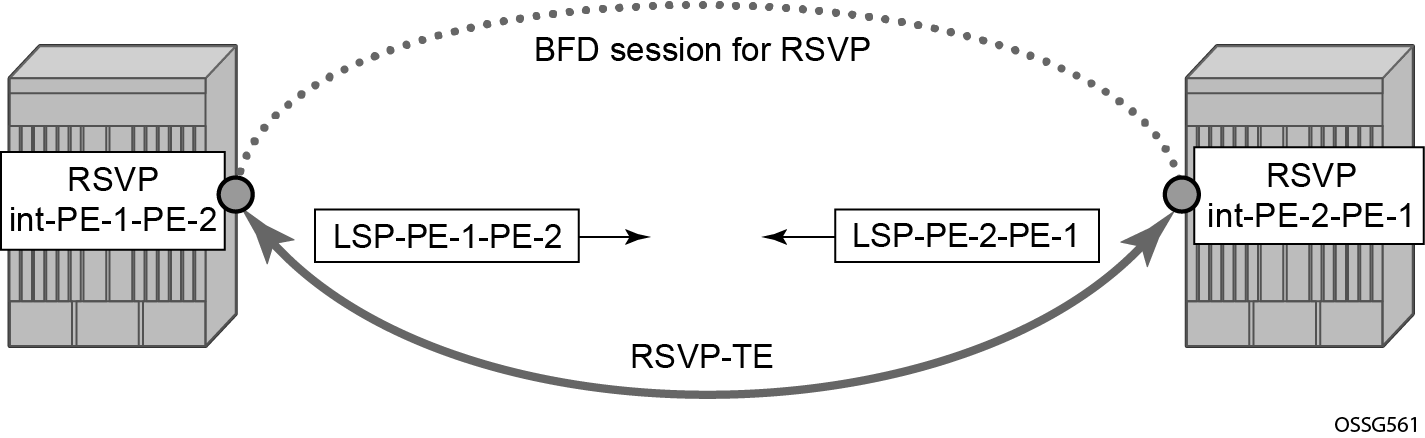
BFD for RSVP
The goal of this section is to configure BFD between two RSVP interfaces configured in two SR OS nodes. BFD for RSVP shows the topology for this scenario.
BFD is configured on the interfaces between PE-1 and PE-2 as described in BFD base parameter configuration and troubleshooting.
The following commands on PE-1 and PE-2 configure the paths, the LSPs, and the interfaces within MPLS and RSVP.
# on PE-1:
configure
    router Base
        mpls
            interface "system"
                no shutdown
            exit
            interface "int-PE-1-PE-2"
                no shutdown
            exit
        exit
        rsvp
            interface "system"
                no shutdown
            exit
            interface "int-PE-1-PE-2"
                no shutdown
            exit
            no shutdown
        exit
        mpls
            path "empty"
                no shutdown
            exit
            lsp "LSP-PE-1-PE-2"
                to 192.0.2.2
                path-computation-method local-cspf
                primary "empty"
                exit
                no shutdown
            exit
            no shutdown
        exit
# on PE-2:
configure
    router Base
        mpls
            interface "system"
                no shutdown
            exit
            interface "int-PE-2-PE-1"
                no shutdown
            exit
        exit
        rsvp
            interface "system"
                no shutdown
            exit
            interface "int-PE-2-PE-1"
                no shutdown
            exit
            no shutdown
        exit
        mpls
            path "empty"
                no shutdown
            exit
            lsp "LSP-PE-2-PE-1"
                to 192.0.2.1
                path-computation-method local-cspf
                primary "empty"
                exit
                no shutdown
            exit
            no shutdown
        exit
The following command on PE-1 verifies that the RSVP sessions are up.
*A:PE-1# show router rsvp session

===============================================================================
RSVP Sessions
===============================================================================
RSVP Session Name
    From                To              Tunnel ID   LSP ID       State
-------------------------------------------------------------------------------
LSP-PE-1-PE-2::empty
192.0.2.1           192.0.2.2           1           20480        Up

LSP-PE-2-PE-1::empty
192.0.2.2           192.0.2.1           1           42496        Up

-------------------------------------------------------------------------------
Sessions : 2
===============================================================================
The following commands on PE-1 and PE-2 enable BFD on the RSVP interfaces.
# on PE-1:
configure
    router Base
        rsvp
            interface "int-PE-1-PE-2"
                bfd-enable
            exit
# on PE-2:
configure
    router Base
        rsvp
            interface "int-PE-2-PE-1"
                bfd-enable
            exit
The following commands verify that the BFD session is operational between PE-1 and PE-2.
On PE-1:
*A:PE-1# show router bfd session

===============================================================================
Legend:
  Session Id = Interface Name | LSP Name | Prefix | RSVP Sess Name | Service Id
  wp = Working path   pp = Protecting path
===============================================================================
BFD Session
===============================================================================
Session Id                                        State      Tx Pkts    Rx Pkts
  Rem Addr/Info/SdpId:VcId                      Multipl     Tx Intvl   Rx Intvl
  Protocols                                        Type     LAG Port     LAG ID
  Loc Addr                                                             LAG name
-------------------------------------------------------------------------------
int-PE-1-PE-2                                        Up           97         91
  192.168.12.2                                        3          100        100
  rsvp                                              iom          N/A        N/A
  192.168.12.1
-------------------------------------------------------------------------------
No. of BFD sessions: 1
===============================================================================
On PE-2:
*A:PE-2# show router bfd session

===============================================================================
Legend:
  Session Id = Interface Name | LSP Name | Prefix | RSVP Sess Name | Service Id
  wp = Working path   pp = Protecting path
===============================================================================
BFD Session
===============================================================================
Session Id                                        State      Tx Pkts    Rx Pkts
  Rem Addr/Info/SdpId:VcId                      Multipl     Tx Intvl   Rx Intvl
  Protocols                                        Type     LAG Port     LAG ID
  Loc Addr                                                             LAG name
-------------------------------------------------------------------------------
int-PE-2-PE-1                                        Up           70         70
  192.168.12.1                                        3          100        100
  rsvp                                              iom          N/A        N/A
  192.168.12.2
-------------------------------------------------------------------------------
No. of BFD sessions: 1
===============================================================================
BFD for T-LDP
BFD tracking of an LDP session associated with a T-LDP adjacency allows for faster detection of the liveliness of the session by registering the transport address of an LDP session with a BFD session. BFD for T-LDP shows the topology.
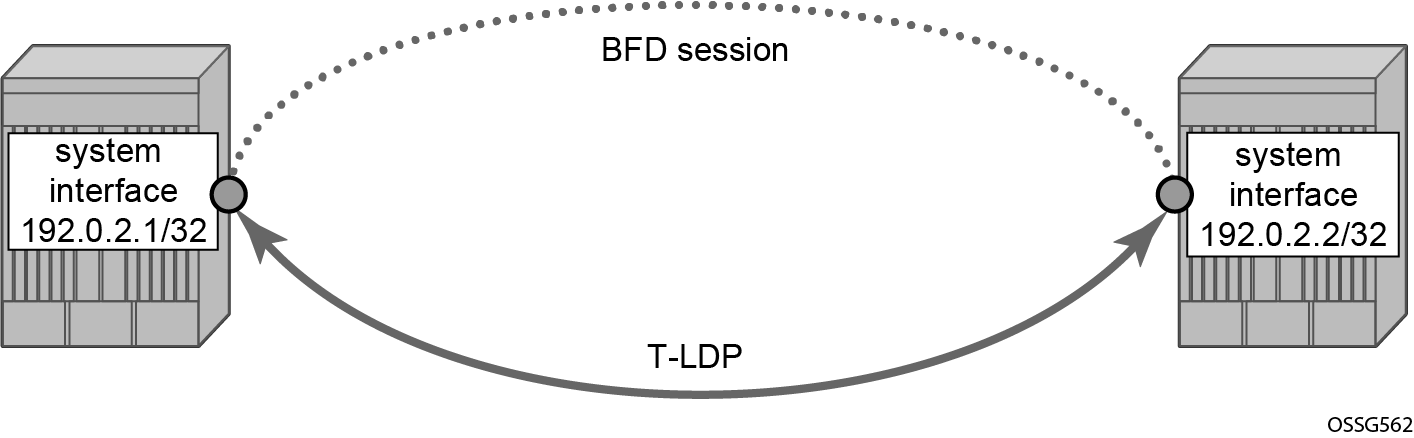
The parameters used for the BFD session are configured under the loopback interface corresponding to the LSR-ID (by default, the LSR-ID matches the system interface address).
# on PE-1, PE-2:
configure
    router Base
        interface "system"
            bfd 3000 receive 3000 multiplier 3
The loopback interface can be used to source BFD sessions to many peers in the network.
When using BFD over other links with the ability to reroute, such as spoke-SDPs, the interval and multiplier values configuring BFD should be set to allow sufficient time for the underlying network to re-converge before the associated BFD session expires. A general rule of thumb should be that the expiration time (interval * multiplier) is three times the convergence time for the IGP network between the two endpoints of the BFD session.
# on PE-1:
configure
    router Base
        ldp
            targeted-session
                peer 192.0.2.2
                    bfd-enable
                    no shutdown
                exit
# on PE-2:
configure
    router Base
        ldp
            targeted-session
                peer 192.0.2.1
                    bfd-enable
                    no shutdown
                exit
By enabling BFD for a selected targeted session, the state of that session is tied to the state of the underlying BFD session between the two nodes.
The following commands on PE-1 and PE-2 verify that the T-LDP session is up.
On PE-1:
*A:PE-1# show router ldp session ipv4

==============================================================================
LDP IPv4 Sessions
==============================================================================
Peer LDP Id         Adj Type  State         Msg Sent  Msg Recv  Up Time
------------------------------------------------------------------------------
192.0.2.2:0         Targeted  Established   71        73        0d 00:05:51
------------------------------------------------------------------------------
No. of IPv4 Sessions: 1
==============================================================================
On PE-2:
*A:PE-1# show router ldp session ipv4

==============================================================================
LDP IPv4 Sessions
==============================================================================
Peer LDP Id         Adj Type  State         Msg Sent  Msg Recv  Up Time
------------------------------------------------------------------------------
192.0.2.2:0         Targeted  Established   71        73        0d 00:05:51
------------------------------------------------------------------------------
No. of IPv4 Sessions: 1
==============================================================================
The following commands on PE-1 and PE-2 show that the BFD session is up.
On PE-1:
*A:PE-1# show router bfd session

===============================================================================
Legend:
  Session Id = Interface Name | LSP Name | Prefix | RSVP Sess Name | Service Id
  wp = Working path   pp = Protecting path
===============================================================================
BFD Session
===============================================================================
Session Id                                        State      Tx Pkts    Rx Pkts
  Rem Addr/Info/SdpId:VcId                      Multipl     Tx Intvl   Rx Intvl
  Protocols                                        Type     LAG Port     LAG ID
  Loc Addr                                                             LAG name
-------------------------------------------------------------------------------
system                                               Up          N/A        N/A
  192.0.2.2                                           3         3000       3000
  ldp                                            cpm-np          N/A        N/A
  192.0.2.1
-------------------------------------------------------------------------------
No. of BFD sessions: 1
===============================================================================
On PE-2:
*A:PE-2# show router bfd session

===============================================================================
Legend:
  Session Id = Interface Name | LSP Name | Prefix | RSVP Sess Name | Service Id
  wp = Working path   pp = Protecting path
===============================================================================
BFD Session
===============================================================================
Session Id                                        State      Tx Pkts    Rx Pkts
  Rem Addr/Info/SdpId:VcId                      Multipl     Tx Intvl   Rx Intvl
  Protocols                                        Type     LAG Port     LAG ID
  Loc Addr                                                             LAG name
-------------------------------------------------------------------------------
system                                               Up          N/A        N/A
  192.0.2.1                                           3         3000       3000
  ldp                                            cpm-np          N/A        N/A
  192.0.2.2
-------------------------------------------------------------------------------
No. of BFD sessions: 1
===============================================================================
When the T-LDP session comes up, a centralized BFD session is always created (cpm-np) even if the local interface has a direct link to the peer.
BFD for OSPF PE-CE adjacencies
BFD for OSPF PE-CE adjacencies extends BFD support to OSPF within a vprn context when OSPF is used as the PE-CE protocol. BFD for OSPF PE-CE interfaces shows the topology used in this section.
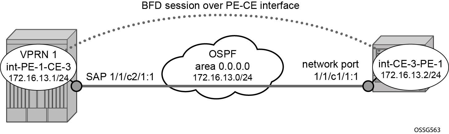
On PE-1, the following VPRN 1 configuration includes service interface int-PE-1-CE-1 with BFD parameters.
# on PE-1:
configure
    service
        vprn 1 name "VPRN-1" customer 1 create
            interface "int-PE-1-CE-3" create
                address 172.16.13.1/24
                bfd 100 receive 100 multiplier 3
                sap 1/1/c2/1:1 create
                exit
            exit
            ospf
                area 0.0.0.0
                    interface "int-PE-1-CE-3"
                        bfd-enable
                        no shutdown
                    exit
                exit
                no shutdown
            exit
            no shutdown
        exit
On CE-3, the following configures the router interface int-CE-3-PE-1 with BFD parameters. BFD is enabled on this interfaces that is added to the OSPF area 0.0.0.0 domain.
# on CE-3:
configure
    router Base
        interface "int-CE-3-PE-1"
            address 172.16.13.2/24
            port 1/1/c1/1:1
            bfd 100 receive 100 multiplier 3
            no shutdown
        exit
        interface "system"
            address 192.0.2.3/32
            no shutdown
        exit
        ospf 0
            area 0.0.0.0
                interface "int-CE-3-PE-1"
                    bfd-enable
                    no shutdown
                exit
            exit
            no shutdown
        exit
The following command shows that the OSPF adjacency is up.
On PE-1:
*A:PE-1# show router 1 ospf neighbor

===============================================================================
Rtr vprn1 OSPFv2 Instance 0 Neighbors
===============================================================================
Interface-Name                   Rtr Id          State      Pri  RetxQ   TTL
   Area-Id
-------------------------------------------------------------------------------
int-PE-1-CE-3                    192.0.2.3       Full       1    0       33
   0.0.0.0
-------------------------------------------------------------------------------
No. of Neighbors: 1
===============================================================================
On CE-3:
*A:CE-3# show router ospf neighbor

===============================================================================
Rtr Base OSPFv2 Instance 0 Neighbors
===============================================================================
Interface-Name                   Rtr Id          State      Pri  RetxQ   TTL
   Area-Id
-------------------------------------------------------------------------------
int-CE-3-PE-1                    192.0.2.1       Full       1    0       34
   0.0.0.0
-------------------------------------------------------------------------------
No. of Neighbors: 1
===============================================================================
The following commands show that the BFD session is up in both PE-1 and CE-3.
*A:PE-1# show router 1 bfd session

===============================================================================
Legend:
  Session Id = Interface Name | LSP Name | Prefix | RSVP Sess Name | Service Id
  wp = Working path   pp = Protecting path
===============================================================================
BFD Session
===============================================================================
Session Id                                        State      Tx Pkts    Rx Pkts
  Rem Addr/Info/SdpId:VcId                      Multipl     Tx Intvl   Rx Intvl
  Protocols                                        Type     LAG Port     LAG ID
  Loc Addr                                                             LAG name
-------------------------------------------------------------------------------
int-PE-1-CE-3                                        Up          507        500
  172.16.13.2                                         3          100        100
  ospf2                                             iom          N/A        N/A
  172.16.13.1
-------------------------------------------------------------------------------
No. of BFD sessions: 1
===============================================================================
*A:CE-3# show router bfd session

===============================================================================
Legend:
  Session Id = Interface Name | LSP Name | Prefix | RSVP Sess Name | Service Id
  wp = Working path   pp = Protecting path
===============================================================================
BFD Session
===============================================================================
Session Id                                        State      Tx Pkts    Rx Pkts
  Rem Addr/Info/SdpId:VcId                      Multipl     Tx Intvl   Rx Intvl
  Protocols                                        Type     LAG Port     LAG ID
  Loc Addr                                                             LAG name
-------------------------------------------------------------------------------
int-CE-3-PE-1                                        Up          210        209
  172.16.13.1                                         3          100        100
  ospf2                                             iom          N/A        N/A
  172.16.13.2
-------------------------------------------------------------------------------
No. of BFD sessions: 1
===============================================================================
BFD for VRRP
This feature assigns a BFD session to provide a heart-beat mechanism for the VRRP instance. There can be only one BFD session assigned to any VRRP instance, but there can be multiple VRRP sessions using the same BFD session. BFD for VRRP shows the topology for this section.
Host 1 and host 2 are connected to LAN subnet 192.168.1.0/24. PE-1 and PE-2 are connected to the LAN subnet by IES or VPRN services. In the following example, IES 10 is created on PE-1 and PE-2 and BFD parameters are configured on the IES interface.
# on PE-1:
configure
    service
        ies 10 name "IES-10" customer 1 create
            interface "int-vrrp-ies-PE-1" create
                address 192.168.1.1/24
                bfd 100 receive 100 multiplier 10
                sap 1/1/c2/1:10 create
                exit
            exit
            no shutdown
        exit
# on PE-2:
configure
    service
        ies 10 name "IES-10" customer 1 create
            interface "int-vrrp-ies-PE-2" create
                address 192.168.1.2/24
                bfd 100 receive 100 multiplier 10
                sap 1/1/c1/1:10 create
                exit
            exit
            no shutdown
        exit
The following command on PE-1 verifies that the IES service "IES-10" is operational:
*A:PE-1# show service service-using ies

===============================================================================
Services [ies]
===============================================================================
ServiceId    Type      Adm  Opr  CustomerId Service Name
-------------------------------------------------------------------------------
2            IES       Up   Up   1          IES-2
10           IES       Up   Up   1          IES-10
2147483648   IES       Up   Down 1          _tmnx_InternalIesService
-------------------------------------------------------------------------------
Matching Services : 3
-------------------------------------------------------------------------------
===============================================================================
*A:PE-1# ping 192.168.1.2 rapid
PING 192.168.1.2 56 data bytes
!!!!!
---- 192.168.1.2 PING Statistics ----
5 packets transmitted, 5 packets received, 0.00% packet loss
round-trip min = 3.55ms, avg = 3.81ms, max = 4.01ms, stddev = 0.155ms
On PE-1 and PE-2, VRRP is enabled on the IES interface that connects to the 192.168.1.0/24 subnet. In this section, the configurations are shown for the VRRP owner mode for primary but any other scenario for VRRP can be configured (non owner mode for primary). In the following example, two VRRP instances are created on the 192.168.1.0/24 subnet:
     VRID = 10  Owner   = PE-1
                Backup  = PE-2
                VRRP IP = 192.168.1.1
     VRID = 30  Owner   = PE-2
                Backup  = PE-1
                VRRP IP = 192.168.1.2
Host 1 is configured with default gateway 192.168.1.1, and host 2 is configured with default gateway 192.168.1.2.
The VRRP configuration on PE-1 is as follows:
configure
    service
        ies 10 name "IES-10" customer 1 create
            interface "int-vrrp-ies-PE-1" create
                vrrp 10 owner
                    backup 192.168.1.1
                exit
                vrrp 30
                    backup 192.168.1.2
                    ping-reply
                    telnet-reply
                    ssh-reply
                exit
The VRRP configuration on PE-2 is as follows:
configure
    service
        ies 10 name "IES-10" customer 1 create
            interface "int-vrrp-ies-PE-2"
                vrrp 10
                    backup 192.168.1.1
                    ping-reply
                    telnet-reply
                    ssh-reply
                exit
                vrrp 30 owner
                    backup 192.168.1.2
                exit
            exit
To bind the VRRP instances with a BFD session, add the following command under any VRRP instance: bfd-enable name <service-name> interface <interface-name> dst-ip <ip-address>. The IES service ID must be declared where the interface is configured. Instead of configuring the service name, it is possible to configure the service ID: bfd-enable <service-id> interface <interface-name> dst-ip <ip-address>.
On PE-1, the following commands enable BFD in IES "IES-10" for VRRP 10 and VRRP 30:
configure
    service
        ies 10 name "IES-10" customer 1 create
            interface "int-vrrp-ies-PE-1"
                vrrp 10 owner
                    bfd-enable name "IES-10" interface "int-vrrp-ies-PE-1" dst-ip 192.168.1.2
                exit
                vrrp 30
                    bfd-enable name "IES-10" interface "int-vrrp-ies-PE-1" dst-ip 192.168.1.2
                exit
            exit
On PE-2, the following commands enable BFD in IES "IES-10" for VRRP 10 and VRRP 30:
configure
    service
        ies 10 name "IES-10" customer 1 create
            interface "int-vrrp-ies-PE-2"
                vrrp 10
                    bfd-enable name "IES-10" interface "int-vrrp-ies-PE-2" dst-ip 192.168.1.1
                exit
                vrrp 30 owner
                    bfd-enable name "IES-10" interface "int-vrrp-ies-PE-2" dst-ip 192.168.1.1
                exit
            exit
The parameters used for the BFD are set by the BFD command under the IP interface. Unlike the previous scenarios, the user can enter the preceding commands, enabling the BFD session, even if the specified interface (int-vrrp-ies-PE-1) has not been configured with BFD parameters.
If the BFD parameters have not been configured yet, the BFD session will be initiated only after the following configuration:
# on PE-1:
configure
    service
        ies 10 name "IES-10" customer 1 create
            interface "int-vrrp-ies-PE-1" create
                bfd 100 receive 100 multiplier 10
# on PE-2:
configure
    service
        ies 10 name "IES-10" customer 1 create
            interface "int-vrrp-ies-PE-2" create
                bfd 100 receive 100 multiplier 10
The following command on PE-1 shows that the BFD session is up:
*A:PE-1# show router bfd session src 192.168.1.1 detail

===============================================================================
BFD Session
===============================================================================
Remote Address : 192.168.1.2
Local Address  : 192.168.1.1
Admin State    : Up                       Oper State       : Up
Protocols      : vrrp
Rx Interval    : 100                      Tx Interval      : 100
Multiplier     : 10                       Echo Interval    : 0
Recd Msgs      : 36033                    Sent Msgs        : 36032
Up Time        : 0d 03:00:45              Up Transitions   : 1
Last Down Time : 0d 00:00:10              Down Transitions : 0
                                          Version Mismatch : 0

Forwarding Information

Local Discr    : 1                        Local State      : Up
Local Diag     : 0 (None)                 Local Mode       : Async
Local Min Tx   : 100                      Local Mult       : 10
Last Sent      : 04/18/2023 09:50:22      Local Min Rx     : 100
Type           : iom
Remote Discr   : 1                        Remote State     : Up
Remote Diag    : 0 (None)                 Remote Mode      : Async
Remote Min Tx  : 100                      Remote Mult      : 10
Remote C-flag  : 1
Last Recv      : 04/18/2023 09:50:22      Remote Min Rx    : 100
===============================================================================
===============================================================================
This session is shared by all the VRRP instances configured between the specified interfaces.
When BFD is configured in a VRRP instance, the following command gives details of BFD related to every instance:
*A:PE-1# show router vrrp instance interface "int-vrrp-ies-PE-1"

===============================================================================
VRRP Instances for interface "int-vrrp-ies-PE-1"
===============================================================================
-------------------------------------------------------------------------------
VRID 10
-------------------------------------------------------------------------------
Owner               : Yes                 VRRP State        : Master
Primary IP of Master: 192.168.1.1 (Self)
Primary IP          : 192.168.1.1         Standby-Forwarding: Disabled
VRRP Backup Addr    : 192.168.1.1
Admin State         : Up                  Oper State        : Up
Up Time             : 04/18/2023 06:49:27 Virt MAC Addr     : 00:00:5e:00:01:0a
Auth Type           : None
Config Mesg Intvl   : 1                   In-Use Mesg Intvl : 1
Base Priority       : 255                 In-Use Priority   : 255
Init Delay          : 0                   Init Timer Expires: 0.000 sec
Creation State      : Active

-------------------------------------------------------------------------------
BFD Interface
-------------------------------------------------------------------------------
Service ID          : 10
Interface Name      : int-vrrp-ies-PE-1
Src IP              : 192.168.1.1
Dst IP              : 192.168.1.2
Session Oper State  : connected

-------------------------------------------------------------------------------
Master Information
-------------------------------------------------------------------------------
Primary IP of Master: 192.168.1.1 (Self)
Addr List Mismatch  : No                  Master Priority   : 255
Master Since        : 04/18/2023 06:49:27

-------------------------------------------------------------------------------
Masters Seen (Last 32)
-------------------------------------------------------------------------------
Primary IP of Master   Last Seen             Addr List Mismatch     Msg Count
-------------------------------------------------------------------------------
192.168.1.1            04/18/2023 06:49:27   No                             0

-------------------------------------------------------------------------------
Statistics
-------------------------------------------------------------------------------
Become Master       : 1                   Master Changes    : 1
Adv Sent            : 10948               Adv Received      : 0
Pri Zero Pkts Sent  : 0                   Pri Zero Pkts Rcvd: 0
Preempt Events      : 0                   Preempted Events  : 0
Mesg Intvl Discards : 0                   Mesg Intvl Errors : 0
Addr List Discards  : 0                   Addr List Errors  : 0
Auth Type Mismatch  : 0                   Auth Failures     : 0
Invalid Auth Type   : 0                   Invalid Pkt Type  : 0
IP TTL Errors       : 0                   Pkt Length Errors : 0
Total Discards      : 0

-------------------------------------------------------------------------------
VRID 30
-------------------------------------------------------------------------------
Owner               : No                  VRRP State        : Backup
Primary IP of Master: 192.168.1.2 (Other)
Primary IP          : 192.168.1.1         Standby-Forwarding: Disabled
VRRP Backup Addr    : 192.168.1.2
Admin State         : Up                  Oper State        : Up
Up Time             : 04/18/2023 06:49:27 Virt MAC Addr     : 00:00:5e:00:01:1e
Auth Type           : None
Config Mesg Intvl   : 1                   In-Use Mesg Intvl : 1
Master Inherit Intvl: No
Base Priority       : 100                 In-Use Priority   : 100
Policy ID           : n/a                 Preempt Mode      : Yes
Ping Reply          : Yes                 Telnet Reply      : Yes
Ntp Reply           : No
SSH Reply           : Yes                 Traceroute Reply  : No
Init Delay          : 0                   Init Timer Expires: 0.000 sec
Creation State      : Active

-------------------------------------------------------------------------------
BFD Interface
-------------------------------------------------------------------------------
Service ID          : 10
Interface Name      : int-vrrp-ies-PE-1
Src IP              : 192.168.1.1
Dst IP              : 192.168.1.2
Session Oper State  : connected

-------------------------------------------------------------------------------
Master Information
-------------------------------------------------------------------------------
Primary IP of Master: 192.168.1.2 (Other)
Addr List Mismatch  : No                  Master Priority   : 255
Master Since        : 04/18/2023 06:49:34
Master Down Interval: 3.609 sec (Expires in 2.700 sec)

-------------------------------------------------------------------------------
Masters Seen (Last 32)
-------------------------------------------------------------------------------
Primary IP of Master   Last Seen             Addr List Mismatch     Msg Count
-------------------------------------------------------------------------------
192.168.1.1            04/18/2023 06:49:31   No                             0
192.168.1.2            04/18/2023 09:51:54   No                         10942

-------------------------------------------------------------------------------
Statistics
-------------------------------------------------------------------------------
Become Master       : 1                   Master Changes    : 2
Adv Sent            : 4                   Adv Received      : 10942
Pri Zero Pkts Sent  : 0                   Pri Zero Pkts Rcvd: 0
Preempt Events      : 0                   Preempted Events  : 1
Mesg Intvl Discards : 0                   Mesg Intvl Errors : 0
Addr List Discards  : 0                   Addr List Errors  : 0
Auth Type Mismatch  : 0                   Auth Failures     : 0
Invalid Auth Type   : 0                   Invalid Pkt Type  : 0
IP TTL Errors       : 0                   Pkt Length Errors : 0
Total Discards      : 0

===============================================================================
For troubleshooting, a configuration error is introduced for VRRP 10 in service "IES-10" on PE-1. In this example, the misconfiguration is that the IES service name "IES-10" is not declared in the bfd-enable command for VRRP 10:
# on PE-1:
configure
    service
        ies "IES-10"
            interface "int-vrrp-ies-PE-1"
                vrrp 10 owner
                    no bfd-enable name "IES-10" interface "int-vrrp-ies-PE-1" dst-ip 192.168.1.2
                    bfd-enable interface "int-vrrp-ies-PE-1" dst-ip 192.168.1.2
                exit
In this case, the BFD session between the two IP interfaces is operationally up but the command show router vrrp instance interface <interface-name> on PE-1 gives the following output regarding BFD for VRID 10:
*A:PE-1# show router vrrp instance interface "int-vrrp-ies-PE-1"

===============================================================================
VRRP Instances for interface "int-vrrp-ies-PE-1"
===============================================================================
-------------------------------------------------------------------------------
VRID 10
-------------------------------------------------------------------------------
Owner               : Yes                 VRRP State        : Master
Primary IP of Master: 192.168.1.1 (Self)
Primary IP          : 192.168.1.1         Standby-Forwarding: Disabled
VRRP Backup Addr    : 192.168.1.1
Admin State         : Up                  Oper State        : Up
Up Time             : 04/18/2023 06:49:27 Virt MAC Addr     : 00:00:5e:00:01:0a
Auth Type           : None
Config Mesg Intvl   : 1                   In-Use Mesg Intvl : 1
Base Priority       : 255                 In-Use Priority   : 255
Init Delay          : 0                   Init Timer Expires: 0.000 sec
Creation State      : Active

-------------------------------------------------------------------------------
BFD Interface
-------------------------------------------------------------------------------
Service ID          : None
Interface Name      : int-vrrp-ies-PE-1
Src IP              :
Dst IP              : 192.168.1.2
Session Oper State  : notConfigured

-------------------------------------------------------------------------------
---snip---
The session operational state and the service ID indicate that the service ID is not configured. To fix this, enable BFD with service ID 10 or service name "IES-10" for VRRP instance 10:
# on PE-1:
configure
    service
        ies "IES-10"
            interface "int-vrrp-ies-PE-1"
                vrrp 10 owner
                    no bfd-enable interface "int-vrrp-ies-PE-1" dst-ip 192.168.1.2
                    bfd-enable name "IES-10" interface "int-vrrp-ies-PE-1" dst-ip 192.168.1.2
                exit
Conclusion
BFD is a light-weight protocol which provides rapid path failure detection between two systems. BFD is useful in situations where the physical network has numerous intervening devices which are not part of the Layer 3 network.
BFD is linked to a protocol state. For a BFD session to be established, the prerequisite condition is that the protocol to which the BFD is linked must be operationally active. Once the BFD session is established, the state of the protocol to which BFD is tied to is then determined based on the BFD session’s state. This means that if the BFD session goes down, the corresponding protocol will be brought down.
In this section several scenarios where BFD could be implemented have been described, including the configuration, show output, and troubleshooting hints.