6PE Next-Hop Resolution
This chapter provides information about 6PE next hop resolution.
Topics in this chapter include:
Applicability
This chapter was initially written based on SR OS Release 14.0.R7, but the CLI in the current edition corresponds to SR OS Release 23.7.R1.
In Releases earlier than 14.0.R1, only label distribution protocol label switched paths (LDP LSPs) could be used to resolve IPv6 provider edge (6PE) next hops. Additional options for 6PE next hop resolution are supported in SR OS Release 14.0.R1, and later. In this chapter, examples are shown with 6PE next hop resolution to different kinds of MPLS tunnels, such as LDP, RSVP-TE, SR-ISIS, and BGP tunnels.
Overview
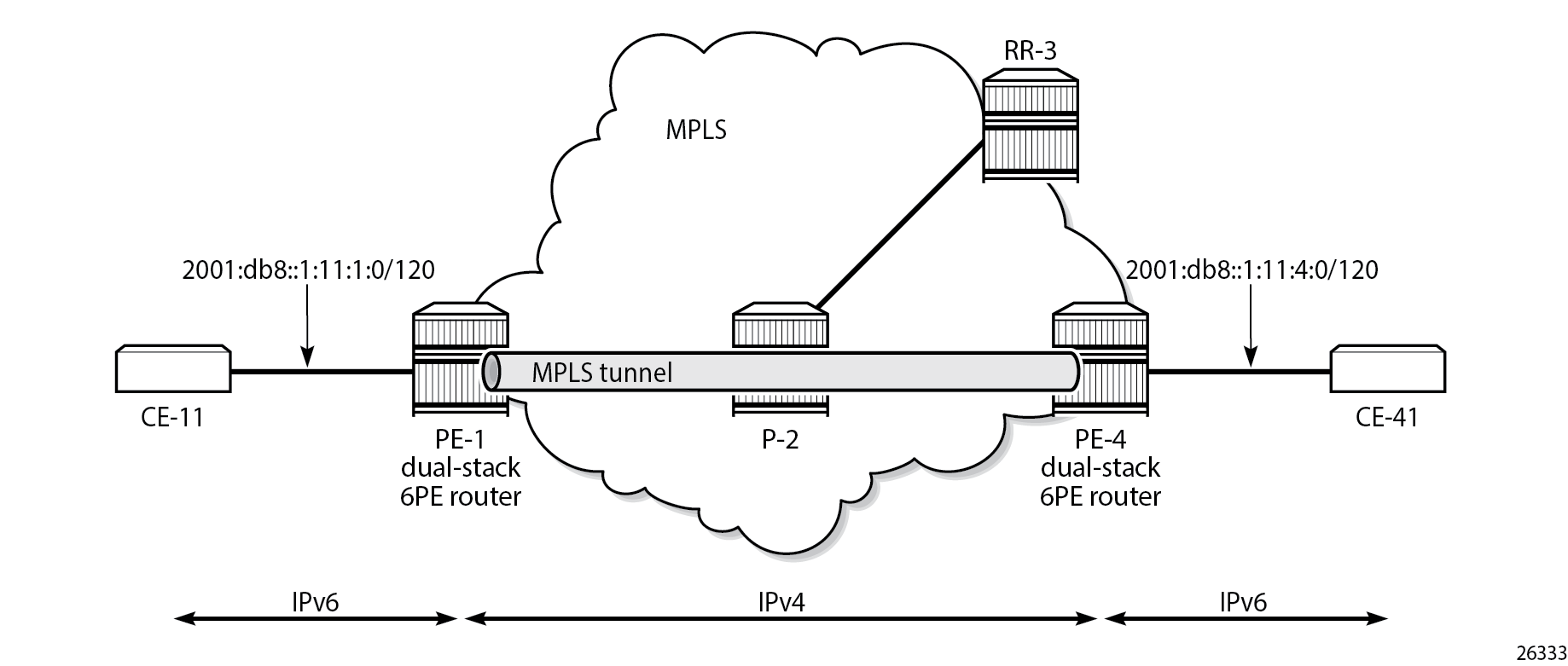
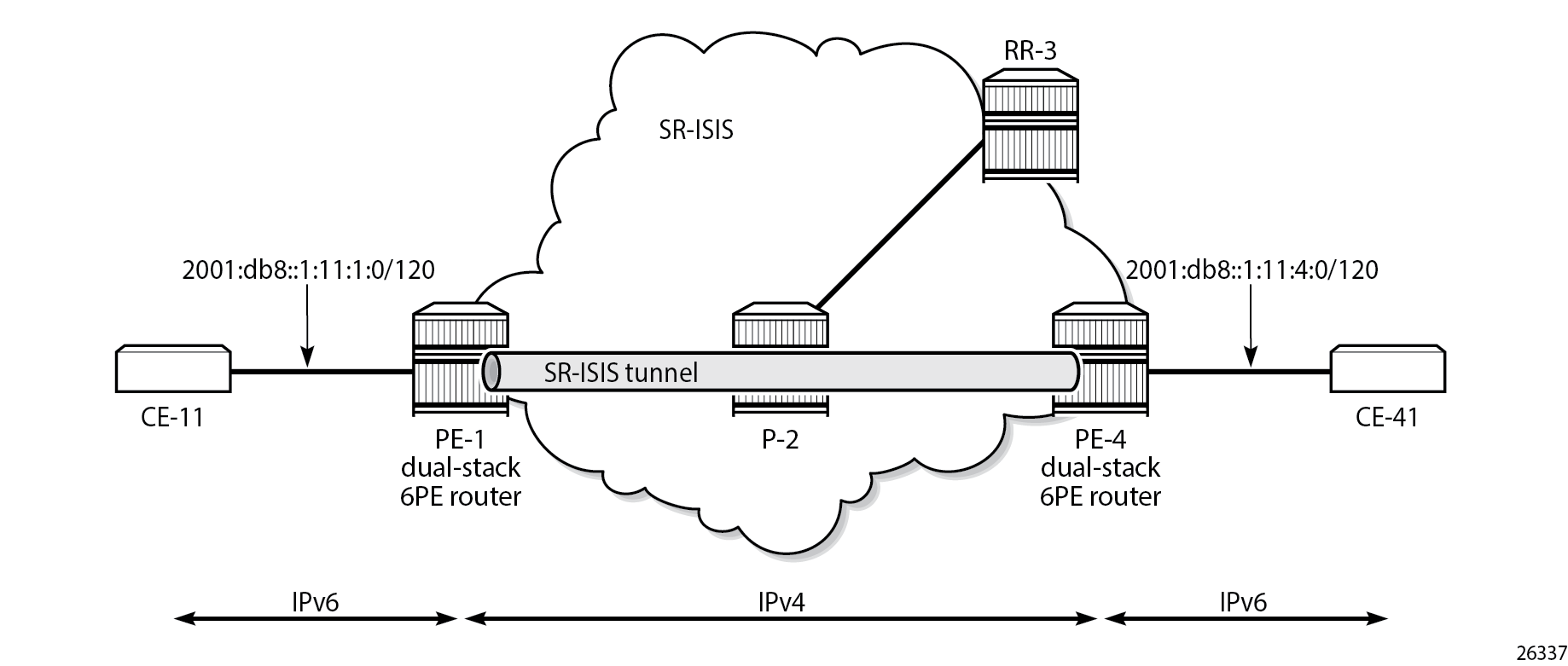
IPv6 provider edge (6PE) enables IPv6 communication between IPv6 domains over an IPv4 multi-protocol label switching (MPLS) cloud. IPv6 packets are forwarded in an MPLS tunnel from one dual-stack 6PE router to another, as shown in IPv6 provider edge (6PE).
The 6PE route next hop resolution is configured using the following command:
#A:PE-1>config>router>bgp>next-hop-res>lbl-routes>transport-tunn>family# resolution ?
  - resolution {any|filter|disabled}
With 6PE next hop resolution set to any, the tunnels are selected based on availability and tunnel table manager (TTM) preference. The order of preference of TTM tunnels is: RSVP, SR-TE, LDP, SR-OSPF, SR-ISIS, and UDP.
For LDP to be used, it is sufficient to enable LDP on the interfaces in the MPLS network.
For RSVP-TE to be used, an RSVP-TE LSP to the 6PE next-hop destination must be available or configured. For segment routing to be used, an SR-signaled path to the 6PE next hop destination must be available or configured. For BGP labeled routes to be used, the 6PE next hop must have been learned via a BGP peering carrying labeled unicast routes and placed in the active route table.
With 6PE next hop resolution set to filter, a subset of protocols is required, and LDP is automatically added to the protocol list in the resolution filter. The following example shows that when one tries to create a resolution filter that includes the BGP protocol only, the resolution filter includes LDP and BGP. The first info command shows that initially no resolution filter had been defined.
*A:PE-1>config>router>bgp>next-hop-res>lbl-routes>transport-tunn>family>res-filter# info
----------------------------------------------
----------------------------------------------
*A:PE-1>config>router>bgp>next-hop-res>lbl-routes>transport-tunn>family>res-filter# info detail
----------------------------------------------
                        ldp
                        no rsvp
                        no sr-isis
                        no sr-ospf
                        no sr-ospf3
                        no bgp
                        no sr-te
                        no udp
                        no sr-policy
                        no rib-api
                        no mpls-fwd-policy
----------------------------------------------
*A:PE-1>config>router>bgp>next-hop-res>lbl-routes>transport-tunn>family>res-filter$ bgp
*A:PE-1>config>router>bgp>next-hop-res>lbl-routes>transport-tunn>family>res-filter$ info
----------------------------------------------
                        ldp
                        bgp
----------------------------------------------
If the 6PE next hop can be resolved to an LDP tunnel, this tunnel is preferred to a BGP tunnel.
It is possible to explicitly exclude LDP from the list, as follows:
*A:PE-1>config>router>bgp>next-hop-res>lbl-routes>transport-tunn>family>res-filter# no ldp
*A:PE-1>config>router>bgp>next-hop-res>lbl-routes>transport-tunn>family>res-filter# info
----------------------------------------------
                        no ldp
                        bgp
----------------------------------------------
Configuration
Example topology shows the example topology with two dual-stack 6PE routers (PE-1 and PE-4), a core router (P-2), and a route reflector (RR-3). IPv4 is used in the core network; IPv6 is used between the CEs and the PEs.
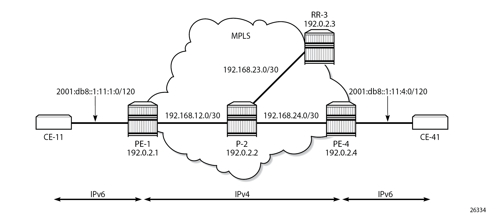
The initial configuration on the nodes is as follows:
Cards, MDAs, ports
Router interfaces
IS-IS as IGP in the core IPv4 network (alternatively, OSPF can be used)
LDP enabled on the interfaces between the PEs and P-2, but not toward RR-3
MPLS and RSVP enabled on the interfaces between the PEs and P-2, but not toward RR-3
BGP configuration
BGP is configured for the label-IPv6 address family on PE-1, PE-4, and RR-3, but not on P-2. The BGP configuration on both PEs defines how the 6PE next hops will be resolved: the resolution filter contains three options (LDP, RSVP, and SR-ISIS). The BGP configuration is identical on PE-1 and PE-4.
# on PE-1, PE-4:
configure
    router Base
        autonomous-system 64496
        bgp
            split-horizon
            next-hop-resolution
                labeled-routes
                    transport-tunnel
                        family label-ipv6
                            resolution-filter
                                ldp     # default
                                rsvp
                                sr-isis
                            exit
                            resolution filter
                        exit
                    exit
                exit
            exit
            group "IBGP"
                export "export-6pe"
                peer-as 64496
                neighbor 192.0.2.3
                    family label-ipv6
                exit
            exit
        exit
The export policy "export-6pe" exports the IPv6 prefixes that are local to the PE, for example, on PE-1: 2001:db8::1:11:1:0/120, and is defined as follows:
# on PE-1, PE-4:
configure
    router Base
        policy-options
            begin
            policy-statement "export-6pe"
                entry 10
                    from
                        protocol direct
                    exit
                    action accept
                    exit
                exit
                default-action drop
                exit
            exit
            commit
The BGP configuration on RR-3 does not include any export policy or any next-hop resolution settings, as follows:
# on RR-3:
configure
    router Base
        autonomous-system 64496
        bgp
            split-horizon
            group "IBGP"
                cluster 192.0.2.3
                peer-as 64496
                neighbor 192.0.2.1
                    family label-ipv6
                exit
                neighbor 192.0.2.4
                    family label-ipv6
                exit
            exit
IES configuration
On PE-1, an IES is configured with IPv6 addresses on the interface toward CE-11, as follows:
# on PE-1:
configure
    service
        ies 1 name "IES-1" customer 1 create
            description "6PE"
            interface "int-PE-1-CE-11" create
                ipv6
                    address 2001:db8::1:11:1:1/120
                exit
                sap 1/1/c3/1:1 create
                exit
            exit
            no shutdown
        exit
The configuration on PE-4 is similar; the IPv6 address on interface "int-PE-4-CE-41" is different: 2001:db8::1:11:4:1/120.
A BGP labeled tunnel, which is active in the routing table, is established between the PEs, as follows:
*A:PE-1# show router route-table ipv6

===============================================================================
IPv6 Route Table (Router: Base)
===============================================================================
Dest Prefix[Flags]                            Type    Proto     Age        Pref
      Next Hop[Interface Name]                                    Metric
-------------------------------------------------------------------------------
2001:db8::1:11:1:0/120                        Local   Local     00h02m38s  0
       int-PE-1-CE-11                                               0
2001:db8::1:11:4:0/120                        Remote  BGP_LABEL 00h01m59s  170
       192.0.2.4 (tunneled)                                         20
-------------------------------------------------------------------------------
No. of Routes: 2
Flags: n = Number of times nexthop is repeated
       B = BGP backup route available
       L = LFA nexthop available
       S = Sticky ECMP requested
===============================================================================
CE-11 can send IPv6 packets with source address 2001:db8::1:11:1:11 to destination address 2001:db8::1:11:4:41 on CE-41, as follows:
*A:PE-1# ping router 11 2001:db8::1:11:4:41 source 2001:db8::1:11:1:11
PING 2001:db8::1:11:4:41 56 data bytes
64 bytes from 2001:db8::1:11:4:41 icmp_seq=1 hlim=62 time=3.65ms.
64 bytes from 2001:db8::1:11:4:41 icmp_seq=2 hlim=62 time=8.41ms.
64 bytes from 2001:db8::1:11:4:41 icmp_seq=3 hlim=62 time=3.03ms.
64 bytes from 2001:db8::1:11:4:41 icmp_seq=4 hlim=62 time=3.09ms.
64 bytes from 2001:db8::1:11:4:41 icmp_seq=5 hlim=62 time=1.71ms.

---- 2001:db8::1:11:4:41 PING Statistics ----
5 packets transmitted, 5 packets received, 0.00% packet loss
round-trip min = 1.71ms, avg = 3.98ms, max = 8.41ms, stddev = 2.31ms
6PE next hop resolved to an LDP tunnel
On PE-1, the route for prefix 2001:db8::1:11:4:0/120 uses a tunnel to 6PE next hop 192.0.2.4, as follows:
*A:PE-1# show router route-table 2001:db8::1:11:4:0/120

===============================================================================
IPv6 Route Table (Router: Base)
===============================================================================
Dest Prefix[Flags]                            Type    Proto     Age        Pref
      Next Hop[Interface Name]                                    Metric
-------------------------------------------------------------------------------
2001:db8::1:11:4:0/120                        Remote  BGP_LABEL 00h02m20s  170
       192.0.2.4 (tunneled)                                         20
-------------------------------------------------------------------------------
No. of Routes: 1
Flags: n = Number of times nexthop is repeated
       B = BGP backup route available
       L = LFA nexthop available
       S = Sticky ECMP requested
===============================================================================
LDP is enabled on the interfaces between the PEs and P-2, which is sufficient for 6PE next hop resolution to an LDP tunnel. RSVP-TE tunnels have a higher priority, but no MPLS LSPs have been configured yet on the PEs. The tunnel table on PE-1 shows that the only tunnel to 6PE next hop 192.0.2.4 is an LDP tunnel, as follows:
*A:PE-1# show router tunnel-table

===============================================================================
IPv4 Tunnel Table (Router: Base)
===============================================================================
Destination           Owner     Encap TunnelId  Pref   Nexthop        Metric
   Color
-------------------------------------------------------------------------------
192.0.2.2/32          ldp       MPLS  65537     9      192.168.12.2   10
192.0.2.4/32          ldp       MPLS  65538     9      192.168.12.2   20
-------------------------------------------------------------------------------
Flags: B = BGP or MPLS backup hop available
       L = Loop-Free Alternate (LFA) hop available
       E = Inactive best-external BGP route
       k = RIB-API or Forwarding Policy backup hop
===============================================================================
Alternatively, the following show command can be used: the only tunnel on slot 1 (card 1) to 6PE next hop 192.0.2.4 is an LDP tunnel:
*A:PE-1# show router fp-tunnel-table 1 192.0.2.4/32

===============================================================================
IPv4 Tunnel Table Display

Legend:
label stack is ordered from bottom-most to top-most
B - FRR Backup
===============================================================================
Destination                                  Protocol         Tunnel-ID
  Lbl/SID
    NextHop                                                   Intf/Tunnel
  Lbl/SID (backup)
    NextHop   (backup)
-------------------------------------------------------------------------------
192.0.2.4/32                                 LDP               -
  524285
    192.168.12.2                                             1/1/c1/1:1000
-------------------------------------------------------------------------------
Total Entries : 1
-------------------------------------------------------------------------------
===============================================================================
The extended route information for IPv6 prefix 2001:db8::1:11:4:0/120 shows that the 6PE next hop 192.0.2.4 is resolved to an LDP tunnel:
*A:PE-1# show router route-table 2001:db8::1:11:4:0/120 extensive

===============================================================================
Route Table (Router: Base)
===============================================================================
Dest Prefix             : 2001:db8::1:11:4:0/120
  Protocol              : BGP_LABEL
  Age                   : 00h03m39s
  Preference            : 170
  Indirect Next-Hop     : 192.0.2.4
    Label               : 2
    QoS                 : Priority=n/c, FC=n/c
    Source-Class        : 0
    Dest-Class          : 0
    ECMP-Weight         : N/A
    Resolving Next-Hop  : 192.0.2.4 (LDP tunnel)
      Metric            : 20
      ECMP-Weight       : N/A
-------------------------------------------------------------------------------
No. of Destinations: 1
===============================================================================
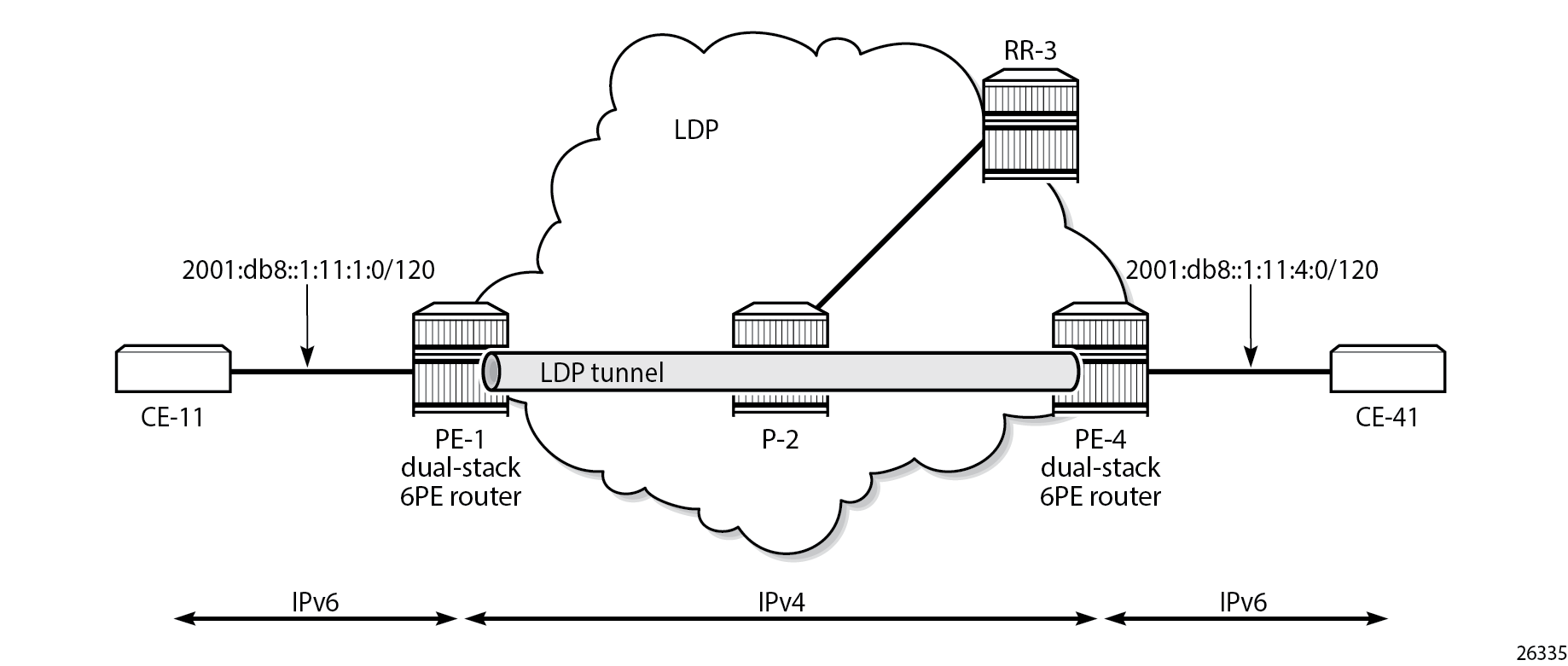
6PE next hop resolved to an LDP tunnel shows that the 6PE next hop is resolved to an LDP tunnel. No other tunnels are available in the IPv4 core network.
6PE next hop resolved to an RSVP-TE tunnel
MPLS and RSVP are enabled on the interfaces between the PEs and P-2. On both PEs, an RSVP-TE LSP is configured toward the peer PE; for example, on PE-1:
# on PE-1:
configure
    router Base
        mpls
            path "empty"
                no shutdown
            exit
            lsp "LSP-PE-1-PE-4"
                to 192.0.2.4
                primary "empty"
                exit
                no shutdown
            exit
The configuration is similar on PE-4. No additional configuration is required on P-2.
The following output shows that two tunnels are available to 6PE next hop 192.0.2.4/32: an LDP tunnel and an RSVP-TE tunnel:
*A:PE-1# show router fp-tunnel-table 1 192.0.2.4/32

===============================================================================
IPv4 Tunnel Table Display

Legend:
label stack is ordered from bottom-most to top-most
B - FRR Backup
===============================================================================
Destination                                  Protocol         Tunnel-ID
  Lbl/SID
    NextHop                                                   Intf/Tunnel
  Lbl/SID (backup)
    NextHop   (backup)
-------------------------------------------------------------------------------
192.0.2.4/32                                 LDP               -
  524285
    192.168.12.2                                             1/1/c1/1:1000
192.0.2.4/32                                 RSVP              1
  524284
    192.168.12.2                                             1/1/c1/1:1000
-------------------------------------------------------------------------------
Total Entries : 2
-------------------------------------------------------------------------------
===============================================================================
For 6PE next hop resolution, RSVP-TE tunnels are preferred to any other tunnel type in the tunnel table, so the BGP next hop 192.0.2.4 will be resolved to an RSVP-TE tunnel, as follows:
*A:PE-1# show router route-table 2001:db8::1:11:4:0/120 extensive

===============================================================================
Route Table (Router: Base)
===============================================================================
Dest Prefix             : 2001:db8::1:11:4:0/120
  Protocol              : BGP_LABEL
  Age                   : 00h00m47s
  Preference            : 170
  Indirect Next-Hop     : 192.0.2.4
    Label               : 2
    QoS                 : Priority=n/c, FC=n/c
    Source-Class        : 0
    Dest-Class          : 0
    ECMP-Weight         : N/A
    Resolving Next-Hop  : 192.0.2.4 (RSVP tunnel:1)
      Metric            : 20
      ECMP-Weight       : N/A
-------------------------------------------------------------------------------
No. of Destinations: 1
===============================================================================
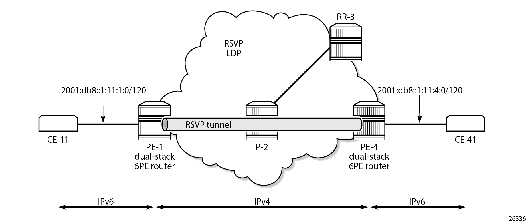
6PE next hop resolved to an RSVP-TE tunnel shows that the 6PE next hop 192.0.2.4 is resolved to an RSVP-TE tunnel, even though an LDP tunnel is available too.
6PE next hop resolved to an SR-ISIS tunnel
Segment routing is enabled for IS-IS on PE-1, P-2, and PE-4. The configuration is similar on each of these nodes; the only difference is the IPv4 node SID index on the system interface. The SR-ISIS configuration on PE-1 is as follows:
# on PE-1:
configure
    router Base
        mpls-labels
            sr-labels start 20000 end 20099
        exit
        isis 0
            advertise-router-capability area
            interface "system"
                ipv4-node-sid index 1
            exit
            segment-routing
                prefix-sid-range start-label 20000 max-index 99
                no shutdown
            exit
        exit
For more information about SR-ISIS, see the Segment Routing with IS-IS Control Plane chapter.
The following output shows that three tunnels are available toward 6PE next hop 192.0.2.4/32:
*A:PE-1# show router fp-tunnel-table 1 192.0.2.4/32

===============================================================================
IPv4 Tunnel Table Display

Legend:
label stack is ordered from bottom-most to top-most
B - FRR Backup
===============================================================================
Destination                                  Protocol         Tunnel-ID
  Lbl/SID
    NextHop                                                   Intf/Tunnel
  Lbl/SID (backup)
    NextHop   (backup)
-------------------------------------------------------------------------------
192.0.2.4/32                                 LDP               -
  524285
    192.168.12.2                                             1/1/c1/1:1000
192.0.2.4/32                                 RSVP              1
  524284
    192.168.12.2                                             1/1/c1/1:1000
192.0.2.4/32                                 SR-ISIS-0         524291
  20004
    192.168.12.2                                             1/1/c1/1:1000
-------------------------------------------------------------------------------
Total Entries : 3
-------------------------------------------------------------------------------
===============================================================================
RSVP-TE tunnels are preferred; therefore, the 6PE next hop 192.0.2.4 is resolved to the RSVP-TE tunnel, as follows:
*A:PE-1# show router route-table 2001:db8::1:11:4:0/120 extensive

===============================================================================
Route Table (Router: Base)
===============================================================================
Dest Prefix             : 2001:db8::1:11:4:0/120
  Protocol              : BGP_LABEL
  Age                   : 00h02m13s
  Preference            : 170
  Indirect Next-Hop     : 192.0.2.4
    Label               : 2
    QoS                 : Priority=n/c, FC=n/c
    Source-Class        : 0
    Dest-Class          : 0
    ECMP-Weight         : N/A
    Resolving Next-Hop  : 192.0.2.4 (RSVP tunnel:1)
      Metric            : 20
      ECMP-Weight       : N/A
-------------------------------------------------------------------------------
No. of Destinations: 1
===============================================================================
To verify that LDP tunnels are preferred over SR-ISIS tunnels, the RSVP-TE LSPs are put in a shutdown state, as follows:
# on PE-1:
configure
    router Base
        mpls
            lsp "LSP-PE-1-PE-4"
                shutdown
The following output shows that two tunnels are available toward 6PE next hop 192.0.2.4/32: an LDP tunnel and an SR-ISIS tunnel.
*A:PE-1# show router fp-tunnel-table 1 192.0.2.4/32

===============================================================================
IPv4 Tunnel Table Display

Legend:
label stack is ordered from bottom-most to top-most
B - FRR Backup
===============================================================================
Destination                                  Protocol         Tunnel-ID
  Lbl/SID
    NextHop                                                   Intf/Tunnel
  Lbl/SID (backup)
    NextHop   (backup)
-------------------------------------------------------------------------------
192.0.2.4/32                                 LDP               -
  524285
    192.168.12.2                                             1/1/c1/1:1000
192.0.2.4/32                                 SR-ISIS-0         524291
  20004
    192.168.12.2                                             1/1/c1/1:1000
-------------------------------------------------------------------------------
Total Entries : 2
-------------------------------------------------------------------------------
===============================================================================
For 6PE next-hop resolution, the LDP tunnel is preferred over the SR-ISIS tunnel, as follows:
*A:PE-1# show router route-table 2001:db8::1:11:4:0/120 extensive

===============================================================================
Route Table (Router: Base)
===============================================================================
Dest Prefix             : 2001:db8::1:11:4:0/120
  Protocol              : BGP_LABEL
  Age                   : 00h00m33s
  Preference            : 170
  Indirect Next-Hop     : 192.0.2.4
    Label               : 2
    QoS                 : Priority=n/c, FC=n/c
    Source-Class        : 0
    Dest-Class          : 0
    ECMP-Weight         : N/A
    Resolving Next-Hop  : 192.0.2.4 (LDP tunnel)
      Metric            : 20
      ECMP-Weight       : N/A
-------------------------------------------------------------------------------
No. of Destinations: 1
===============================================================================
When LDP is disabled on interface "int-PE-1-P-2" on PE-1, the only remaining tunnel is an SR-ISIS tunnel, as follows:
# on PE-1:
configure
    router Base
        ldp
            interface-parameters
                interface "int-PE-1-P-2"
                    shutdown


*A:PE-1# show router fp-tunnel-table 1 192.0.2.4/32

===============================================================================
IPv4 Tunnel Table Display

Legend:
label stack is ordered from bottom-most to top-most
B - FRR Backup
===============================================================================
Destination                                  Protocol         Tunnel-ID
  Lbl/SID
    NextHop                                                   Intf/Tunnel
  Lbl/SID (backup)
    NextHop   (backup)
-------------------------------------------------------------------------------
192.0.2.4/32                                 SR-ISIS-0         524291
  20004
    192.168.12.2                                             1/1/c1/1:1000
-------------------------------------------------------------------------------
Total Entries : 1
-------------------------------------------------------------------------------
===============================================================================
The 6PE next hop 192.0.2.4 is resolved to an SR-ISIS tunnel, as follows:
*A:PE-1# show router route-table 2001:db8::1:11:4:0/120 extensive

===============================================================================
Route Table (Router: Base)
===============================================================================
Dest Prefix             : 2001:db8::1:11:4:0/120
  Protocol              : BGP_LABEL
  Age                   : 00h00m48s
  Preference            : 170
  Indirect Next-Hop     : 192.0.2.4
    Label               : 2
    QoS                 : Priority=n/c, FC=n/c
    Source-Class        : 0
    Dest-Class          : 0
    ECMP-Weight         : N/A
    Resolving Next-Hop  : 192.0.2.4 (SR-ISIS tunnel:524291)
      Metric            : 20
      ECMP-Weight       : N/A
-------------------------------------------------------------------------------
No. of Destinations: 1
===============================================================================
6PE next hop resolved to an SR-ISIS tunnel shows that the 6PE next hop 192.0.2.4 is resolved to an SR-ISIS tunnel after the RSVP-TE LSPs are disabled and LDP is disabled on the interfaces between the PEs and P-2. No other tunnels are available.
6PE next-hop resolution to a BGP IPv4 tunnel
The preceding example cannot be extended with BGP labeled IPv4 tunnels. The reason is that for BGP to work, some underlying MPLS signaling protocol is required, such as RSVP-TE or LDP. Because BGP tunnels have a very low preference, they will not be used when an LDP or RSVP-TE tunnel is available to the 6PE next hop.
This section shows a seamless MPLS example where 6PE next hops are resolved to BGP labeled IPv4 routes, because no LDP tunnel is available to the 6PE next hop in a different IGP topology (in this example, LDP is configured, not RSVP-TE). For a description of this seamless MPLS implementation, see the Seamless MPLS: Isolated IGP/LDP Domains and Labeled BGP chapter.
Example topology for seamless MPLS shows the example topology for seamless MPLS with two aggregation networks and one core network.

Different IS-IS instances are configured: IS-IS instance 0 is configured in the core, whereas IS-IS instance 1 is configured in the aggregation networks. On the area border routers (ABRs) ABR-2 and ABR-3, two instances of IS-IS are configured: IS-IS instance 0 for the core and IS-IS instance 1 for the aggregation network. PE-1 and PE-4 will only learn routes to destinations within their respective aggregation networks; ABRs learn routes within one aggregation network and the core network. LDP is configured on all interfaces, but PE-1 will not have an LDP binding for prefix 192.0.2.4/32, as shown in the following output. Therefore, 6PE next hop 192.0.2.4 cannot be resolved to an LDP tunnel.
*A:PE-1# show router ldp bindings active prefixes ipv4

===============================================================================
LDP Bindings (IPv4 LSR ID 192.0.2.1)
             (IPv6 LSR ID ::)
===============================================================================
Label Status:
        U - Label In Use, N - Label Not In Use, W - Label Withdrawn
        WP - Label Withdraw Pending, BU - Alternate For Fast Re-Route
        e - Label ELC
FEC Flags:
        LF - Lower FEC, UF - Upper FEC, M - Community Mismatch,
        BA - ASBR Backup FEC
        (S) - Static           (M) - Multi-homed Secondary Support
        (B) - BGP Next Hop     (BU) - Alternate Next-hop for Fast Re-Route
        (I) - SR-ISIS Next Hop (O) - SR-OSPF Next Hop
        (C) - FEC resolved with class-based-forwarding
===============================================================================
LDP IPv4 Prefix Bindings (Active)
===============================================================================
Prefix                                      Op
IngLbl                                      EgrLbl
EgrNextHop                                  EgrIf/LspId
-------------------------------------------------------------------------------
192.0.2.1/32                                Pop
524287                                        --
  --                                          --

192.0.2.2/32                                Push
  --                                        524287
192.168.12.2                                1/1/c1/1:1000

-------------------------------------------------------------------------------
No. of IPv4 Prefix Active Bindings: 2
===============================================================================
Configured protocols for seamless MPLS shows the configured protocols for this example: IS-IS instances, LDP, BGP labeled IPv4 with the ABRs as route reflector with next-hop-self (NHS) option, and BGP labeled IPv6 peering between PE-1 and PE-4.
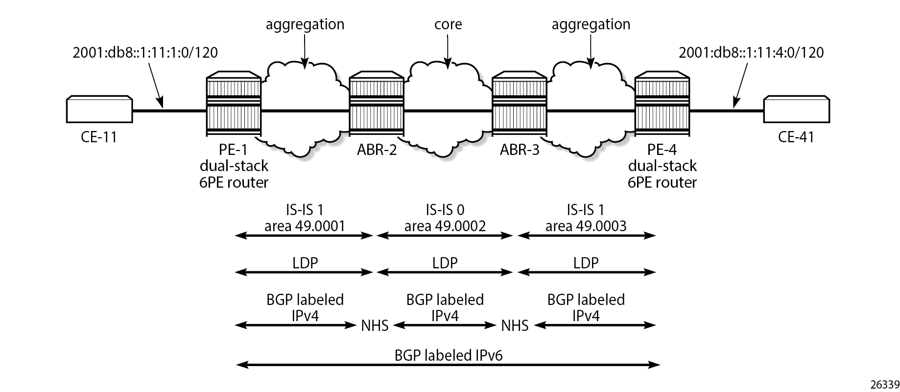
The following initial configuration on ABR-2 includes two IS-IS instances in different areas. IS-IS instance 0 with area ID 49.0002 is configured in the core network; IS-IS instance 1 with area ID 49.0001 is configured in the aggregation network between PE-1 and ABR-2. LDP is configured on each router interface.
# on ABR-2:
configure
    router Base
        interface "int-ABR-2-ABR-3"
            address 192.168.23.1/30
            port 1/1/c3/1:1000
            no shutdown
        exit
        interface "int-ABR-2-PE-1"
            address 192.168.12.2/30
            port 1/1/c2/1:1000
            no shutdown
        exit
        interface "system"
            address 192.0.2.2/32
            no shutdown
        exit
        isis 0
            level-capability level-2
            area-id 49.0002
            interface "system"
                no shutdown
            exit
            interface "int-ABR-2-ABR-3"
                interface-type point-to-point
                no shutdown
            exit
            no shutdown
        exit
        isis 1
            level-capability level-2
            area-id 49.0001
            interface "system"
                no shutdown
            exit
            interface "int-ABR-2-PE-1"
                interface-type point-to-point
                no shutdown
            exit
            no shutdown
        exit
        ldp
            interface-parameters
                interface "int-ABR-2-PE-1" dual-stack
                    ipv4
                        no shutdown
                    exit
                    no shutdown
                exit
                interface "int-ABR-2-ABR-3" dual-stack
                    ipv4
                        no shutdown
                    exit
                    no shutdown
                exit
            exit
        exit
The configuration is similar on the other nodes. Only the ABRs have two IS-IS instances configured; the PEs only have one IS-IS instance.
BGP needs to be configured for the label-IPv4 and label-IPv6 address families:
The label-IPv4 address family is used with the ABRs as RR in the aggregation network. Each ABR is configured with the next-hop-self option. BGP label-IPv4 peering is between the ABRs without RR.
The label-IPv6 address family is used between PE-1 and PE-4. The BGP session can only be established after the BGP labeled IPv4 routes have been exchanged between PE-1 and PE-4.
BGP is configured on PE-1 as follows:
# on PE-1:
configure
    router Base
        autonomous-system 64496
        bgp
            split-horizon
            next-hop-resolution
                labeled-routes
                    transport-tunnel
                        family label-ipv6
                            resolution-filter
                                bgp
                            exit
                            resolution filter
                        exit
                    exit
                exit
            exit
            group "IBGPv4"
                export "export-sys"
                peer-as 64496
                neighbor 192.0.2.2
                    family label-ipv4
                exit
            exit
            group "IBGPv6"
                export "export-6pe"
                peer-as 64496
                neighbor 192.0.2.4
                    family label-ipv6
                exit
            exit
            no shutdown
        exit
The configuration is similar on PE-4, but the neighbor IP addresses are different.
The resolution filter will include LDP as well as BGP, because it is added automatically. However, no LDP tunnel will be available from PE-1 to PE-4, or vice versa; therefore, BGP labeled IPv4 will be used.
The "export-sys" policy exports the IPv4 system address of the PE and is defined as follows:
# on PE-1, PE-4:
configure
    router Base
        policy-options
            begin
            prefix-list "system"
                prefix 192.0.2.0/24 longer
            exit
            policy-statement "export-sys"
                entry 10
                    from
                        protocol direct
                        prefix-list "system"
                    exit
                    action accept
                    exit
                exit
                default-action drop
                exit
            exit
            commit
The "export-6pe" policy exports the local labeled IPv6 routes and is the same in the preceding examples:
# on PE-1, PE-4:
configure
    router Base
        policy-options
            begin
            policy-statement "export-6pe"
                entry 10
                    from
                        protocol direct
                    exit
                    action accept
                    exit
                exit
                default-action drop
                exit
            exit
            commit
The BGP configuration on ABR-2 has two different groups for BGP labeled IPv4 peering: one toward the aggregation network—with the ABR as RR—and one toward the core, as follows:
# on ABR-2:
configure
    router Base
        autonomous-system 64496
        bgp
            advertise-inactive
            split-horizon
            group "IBGPv4-agg"
                next-hop-self
                cluster 192.0.2.2
                peer-as 64496
                neighbor 192.0.2.1
                    family label-ipv4
                exit
            exit
            group "IBGPv4-core"
                next-hop-self
                peer-as 64496
                neighbor 192.0.2.3
                    family label-ipv4
                exit
            exit
            no shutdown
        exit
The configuration is similar on ABR-3, but the neighbor IP addresses and the cluster ID are different.
The ABRs are configured with the next-hop-self option for both groups. The 6PE next hop 192.0.2.4 will have next hop ABR-2 on PE-1, which can be resolved to an LDP tunnel. On ABR-2, 6PE next hop 192.0.2.4 will have ABR-3 as next hop, which can be resolved to an LDP tunnel. On ABR-3, the 6PE next hop 192.0.2.4 can be resolved to an LDP tunnel (no active BGP route to 192.0.2.4/32 on ABR-3 because the route via IS-IS is preferred).
The advertise-inactive option is required for ABR-2 to export a BGP route for prefix 192.0.2.1/32, which is not active on ABR-2, because an IS-IS route is available for this prefix and IS-IS routes are preferred over BGP routes.
The IES configuration is the same as in the preceding example.
When the labeled IPv4 routes are exchanged between PE-1 and PE-4, the BGP labeled session using IPv6 peering can be established between PE-1 and PE-4, as follows:
*A:PE-1# show router bgp summary all

===============================================================================
BGP Summary
===============================================================================
Legend : D - Dynamic Neighbor
===============================================================================
Neighbor
Description
ServiceId          AS PktRcvd InQ  Up/Down   State|Rcv/Act/Sent (Addr Family)
                      PktSent OutQ
-------------------------------------------------------------------------------
192.0.2.2
Def. Inst       64496      12    0 00h03m02s 1/1/1 (Lbl-IPv4)
                           13    0
192.0.2.4
Def. Inst       64496       8    0 00h01m31s 1/1/1 (Lbl-IPv6)
                            8    0

-------------------------------------------------------------------------------
For IPv6 prefix 2001:db8::1:11:4:0/120 on PE-1, 6PE next hop 192.0.2.4 is resolved to a BGP tunnel, as follows:
*A:PE-1# show router route-table 2001:db8::1:11:4:0/120 extensive

===============================================================================
Route Table (Router: Base)
===============================================================================
Dest Prefix             : 2001:db8::1:11:4:0/120
  Protocol              : BGP_LABEL
  Age                   : 00h01m18s
  Preference            : 170
  Indirect Next-Hop     : 192.0.2.4
    Label               : 2
    QoS                 : Priority=n/c, FC=n/c
    Source-Class        : 0
    Dest-Class          : 0
    ECMP-Weight         : N/A
    Resolving Next-Hop  : 192.0.2.4 (BGP tunnel)
      Metric            : 1000
      ECMP-Weight       : N/A
-------------------------------------------------------------------------------
No. of Destinations: 1
===============================================================================
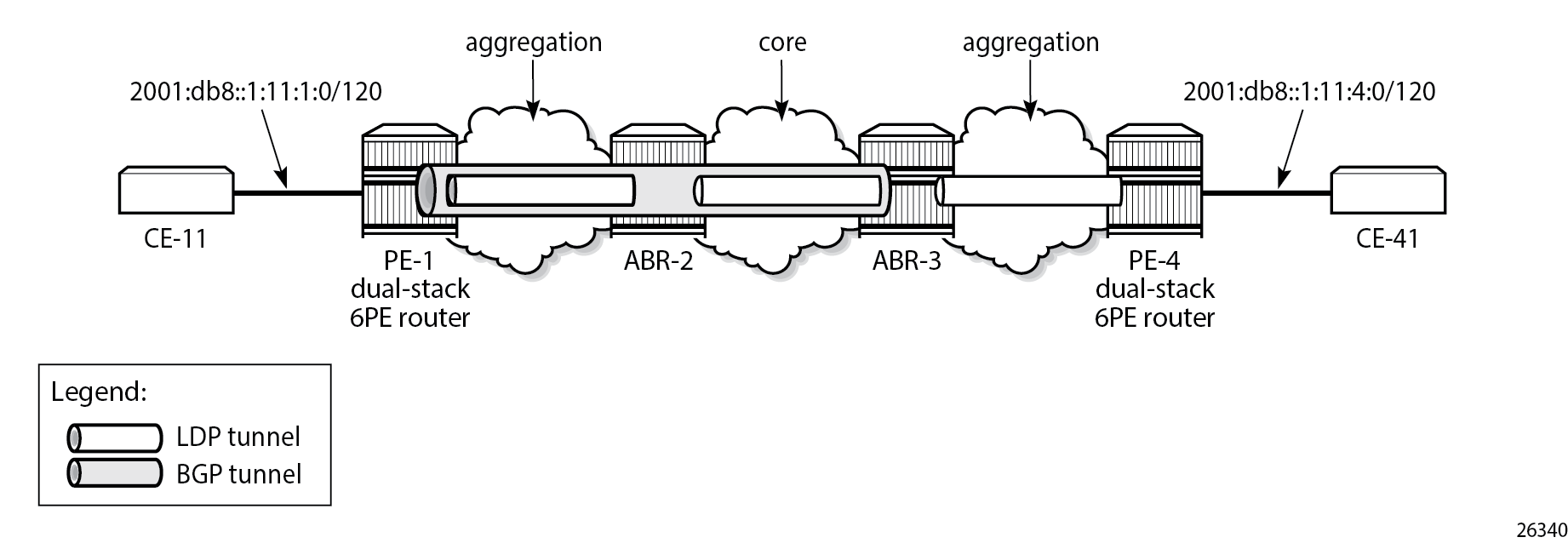
The BGP labeled IPv4 route to 192.0.2.4 has different next hops in different nodes, because both ABRs set the next-hop-self option. On PE-1, the BGP labeled IPv4 route for prefix 192.0.2.4 has next hop 192.0.2.2 and uses an LDP tunnel to reach ABR-2 within the aggregation network, as follows:
*A:PE-1# show router fp-tunnel-table 1 192.0.2.4/32

===============================================================================
IPv4 Tunnel Table Display

Legend:
label stack is ordered from bottom-most to top-most
B - FRR Backup
===============================================================================
Destination                                  Protocol         Tunnel-ID
  Lbl/SID
    NextHop                                                   Intf/Tunnel
  Lbl/SID (backup)
    NextHop   (backup)
-------------------------------------------------------------------------------
192.0.2.4/32                                 BGP               -
  524282
    192.0.2.2                                                LDP
-------------------------------------------------------------------------------
Total Entries : 1
-------------------------------------------------------------------------------
===============================================================================
On ABR-2, the BGP labeled route to 192.0.2.4/32 has next hop 192.0.2.3 and uses an LDP tunnel in the core network to reach ABR-3, as follows:
*A:ABR-2# show router fp-tunnel-table 1 192.0.2.4/32

===============================================================================
IPv4 Tunnel Table Display

Legend:
label stack is ordered from bottom-most to top-most
B - FRR Backup
===============================================================================
Destination                                  Protocol         Tunnel-ID
  Lbl/SID
    NextHop                                                   Intf/Tunnel
  Lbl/SID (backup)
    NextHop   (backup)
-------------------------------------------------------------------------------
192.0.2.4/32                                 BGP               -
  524282
    192.0.2.3                                                LDP
-------------------------------------------------------------------------------
Total Entries : 1
-------------------------------------------------------------------------------
===============================================================================
On ABR-3, no BGP labeled IPv4 route is active for prefix 192.0.2.4 because IS-IS routes are preferred to BGP routes. An LDP tunnel is used toward PE-4 in the aggregation network, as follows:
*A:ABR-3# show router fp-tunnel-table 1 192.0.2.4/32

===============================================================================
IPv4 Tunnel Table Display

Legend:
label stack is ordered from bottom-most to top-most
B - FRR Backup
===============================================================================
Destination                                  Protocol         Tunnel-ID
  Lbl/SID
    NextHop                                                   Intf/Tunnel
  Lbl/SID (backup)
    NextHop   (backup)
-------------------------------------------------------------------------------
192.0.2.4/32                                 LDP               -
  524287
    192.168.34.2                                             1/1/c1/1:1000
-------------------------------------------------------------------------------
Total Entries : 1
-------------------------------------------------------------------------------
===============================================================================
BGP labeled IPv4 tunnel for 192.0.2.4/32 using LDP tunnels shows the BGP and LDP tunnels used for 6PE next hop 192.0.2.4/32.
Conclusion
The 6PE next hops can be resolved to different types of MPLS tunnels, each with a different preference.