Weighted ECMP for 6PE over RSVP-TE LSPs
This chapter provides information about Weighted Equal Cost Multipath (ECMP) for IPv6 Provider Edge (6PE) routers over Resource Reservation Protocol with Traffic Engineering (RSVP-TE) Label Switched Paths (LSPs).
Topics in this chapter include:
Applicability
The information and configuration in this chapter are based on SR OS Release 23.3.R2. Weighted ECMP for 6PE routers over RSVP-TE LSPs is supported in SR OS Release 15.0.R6, and later.
Chapter Weighted ECMP for VPRN over RSVP-TE and SR-TE LSPs is recommended reading.
Overview
Equal Load Balancing
In this chapter, ECMP refers to spraying traffic flows over multiple RSVP-TE LSPs within an ECMP set. ECMP spraying consists of hashing the relevant fields in the packet header and selecting the tunnel next-hop based on the modulo operation of the output of the hash and the number of RSVP-TE LSPs present in the ECMP set. The maximum number of RSVP-TE LSPs in the ECMP set is defined by the ecmp command.
Only RSVP-TE LSPs with the same lowest LSP metric can be part of the ECMP set. If the number of such RSVP-TE LSPs exceeds the maximum number of RSVP-TE LSPs allowed in the ECMP set as defined by the ecmp command, the RSVP-TE LSPs with the lowest tunnel IDs are selected first. By default, all RSVP-TE LSPs in the ECMP set have the same weight, and traffic flows are spread evenly over all RSVP-TE LSPs in the ECMP set, regardless of the bandwidth of the active path in the RSVP-TE LSPs. By default, ECMP is enabled and set to 1.
Unequal Load Balancing
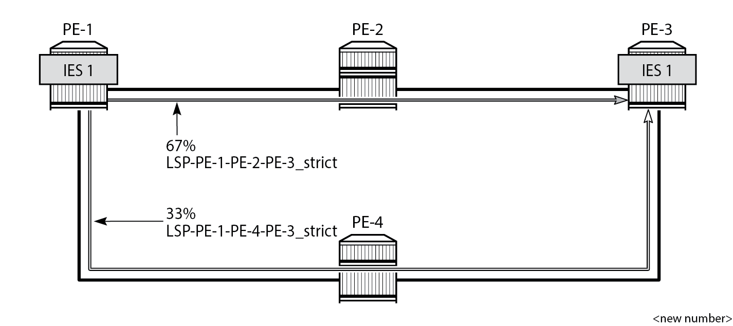
Weighted ECMP sprays traffic flows over RSVP-TE LSPs proportionally to the load-balancing-weight <weight> value configured on each RSVP-TE LSP in the ECMP set. Weighted ECMP in AS 64496 shows that PE-1 forwards two thirds of the traffic flows on LSP-PE-1-PE-2-PE-3_strict with weight 2 and one third on LSP-PE-1-PE-4-PE-3_strict with weight 1.
The LSP load balancing weight can be configured in an LSP template or on an RSVP-TE LSP. By default, the load balancing weight equals zero, in which case regular ECMP applies.
Weighted load balancing can be performed only when all the next-hops are associated with the same neighbor and all the RSVP-TE LSPs are configured with a non-zero load balancing weight. If one or more RSVP-TE LSPs in the ECMP set toward a specific next-hop do not have a load balancing weight configured, regular ECMP spraying is used.
The following command is used to configure the weight in an LSP template:
*A:PE-1# configure router Base mpls lsp-template "LSPtemplate1" load-balancing-weight ?
  - no load-balancing-weight
  - load-balancing-weight <weight>

 <weight>             : [0..4294967295] Default - 0
The following command is used to configure the weight on an LSP (for example on "LSP-PE-1-PE-2-PE-3_strict"):
*A:PE-1# configure router Base mpls lsp "LSP-PE-1-PE-2-PE-3_strict" load-balancing-weight ?
  - load-balancing-weight <weight>
  - no load-balancing-weight

 <weight>             : [0..4294967295] Default - 0
The LSP load balancing weight on LSP-PE-1-PE-2-PE-3_strict is configured with a value of 2, as follows:
configure
    router Base
        mpls
            path "path-PE-1-PE-2-PE-3_strict"
                hop 10 192.168.12.2 strict
                hop 20 192.168.23.2 strict
                no shutdown
            exit
            lsp "LSP-PE-1-PE-2-PE-3_strict"
                to 192.0.2.3
                path-computation-method local-cspf
                metric 100
                load-balancing-weight 2
                primary "path-PE-1-PE-2-PE-3_strict"
                exit
                no shutdown
            exit
Weighted ECMP for 6PE over RSVP-TE LSPs is enabled in the bgp next-hop-resolution context as follows:
configure
    router Base
        bgp
            next-hop-resolution
                weighted-ecmp
The weighted-ecmp option controls load balancing to the same next-hop only.
Configuration
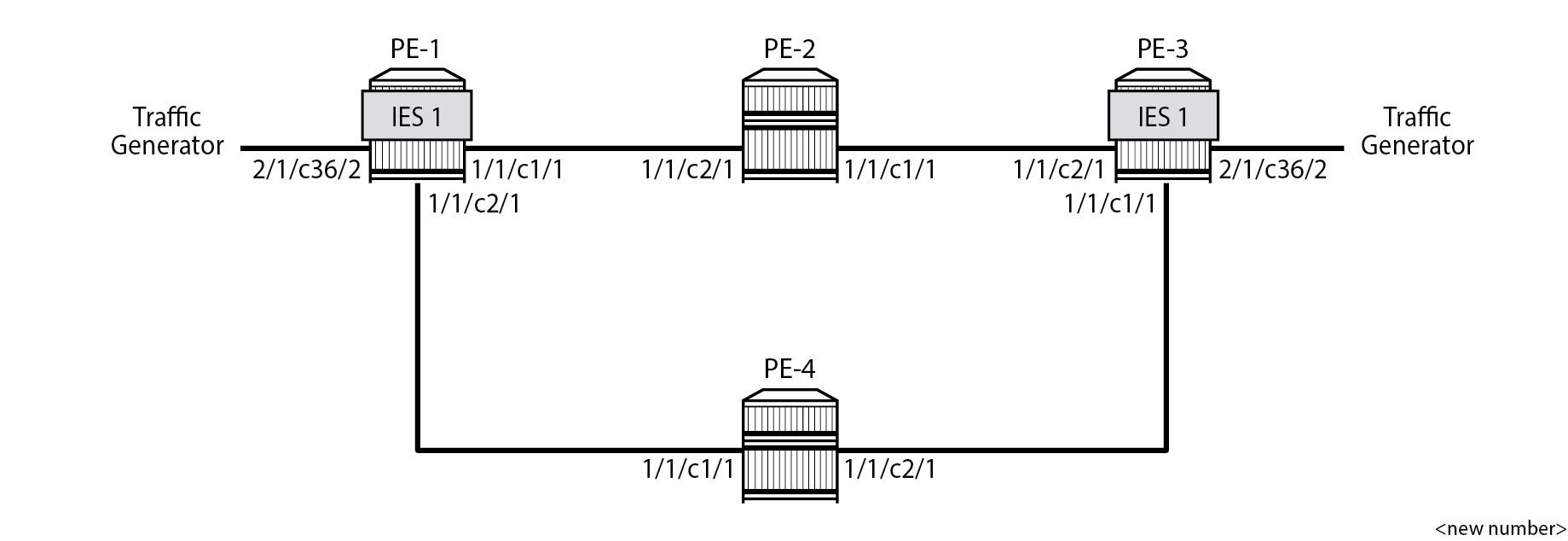
Example Topology for 6PE over RSVP-TE LSPs shows the example topology with four PEs. IES 1 is configured on PE-1 and PE-3. A traffic generator is connected to IES 1 SAP 2/1/c36/2 on PE-1 and IES 1 SAP 2/1/c36/2 on PE-3. The traffic generator generates multiple IPv6 traffic flows with random IP addresses and TCP/UDP port numbers. As a result, these flows are sprayed over different MPLS LSPs between PE-1 and PE-3.
Initial Configuration
The initial configuration on the PEs includes the following:
Cards, MDAs, ports
Router interfaces
IS-IS as IGP (alternatively, OSPF can be used) with traffic engineering enabled
MPLS and RSVP enabled on all router interfaces
MPLS paths with strict hops from PE-1 to PE-3 and the other way around: one via PE-2 and the other via PE-4. The LSP via PE-2 gets a load balancing weight of 2, whereas the LSP via PE-4 gets a load balancing weight of 1. Both LSPs have the same metric.
The initial configuration on PE-1 is as follows.
configure
    router Base
        interface "int-PE-1-PE-2"
            address 192.168.12.1/30
            port 1/1/c1/1
        exit
        interface "int-PE-1-PE-4"
            address 192.168.14.1/30
            port 1/1/c2/1
        exit
        interface "system"
            address 192.0.2.1/32
        exit
        isis 0
            area-id 49.0001
            traffic-engineering
            interface "system"
            exit
            interface "int-PE-1-PE-2"
                interface-type point-to-point
            exit
            interface "int-PE-1-PE-4"
                interface-type point-to-point
            exit
            no shutdown
        exit
        mpls
            interface "int-PE-1-PE-2"
            exit
            interface "int-PE-1-PE-4"
            exit
            path "path-PE-1-PE-2-PE-3_strict"
                hop 10 192.168.12.2 strict
                hop 20 192.168.23.2 strict
                no shutdown
            exit
            path "path-PE-1-PE-4-PE-3_strict"
                hop 10 192.168.14.2 strict
                hop 20 192.168.34.1 strict
                no shutdown
            exit
            lsp "LSP-PE-1-PE-2-PE-3_strict"
                to 192.0.2.3
                path-computation-method local-cspf
                metric 100
                load-balancing-weight 2
                primary "path-PE-1-PE-2-PE-3_strict"
                exit
                no shutdown
            exit
            lsp "LSP-PE-1-PE-4-PE-3_strict"
                to 192.0.2.3
                path-computation-method local-cspf
                metric 100
                load-balancing-weight 1
                primary "path-PE-1-PE-4-PE-3_strict"
                exit
                no shutdown
            exit
            no shutdown
        exit
        rsvp
            no shutdown
        exit
The configuration on PE-3 is similar.
With the preceding configuration, MPLS and RSVP are enabled on all interfaces, including the system interface, which is added automatically.
Weighted ECMP for 6PE over RSVP-TE LSPs
BGP is configured for the label-IPv6 address family and the next-hop resolution is set to RSVP; see the 6PE Next-Hop Resolution chapter.
In this example, the traffic generator sends IPv6 traffic to the SAP in IES 1. The IPv6 packets are tunneled through the IPv4 network between PE-1 and PE-3. The service configuration on PE-1 is as follows:
configure
    service
        ies 1 name "IES-1" customer 1 create
            description "6PE-1"
            interface "int-PE-1-STC" create
                ipv6
                    address 2001:db8::11:1/120
                exit
                sap 2/1/c36/2 create
                exit
            exit
            no shutdown
        exit
The configuration on PE-3 is similar.
On PE-1, the following BGP configuration defines next-hop resolution with weighted ECMP and the resolution filter only allows RSVP-TE LSPs. BGP is configured for the label-IPv6 address family and BGP multipath is configured in the bgp context.
configure
    router Base
        autonomous-system 64496
        bgp
            ibgp-multipath
            split-horizon
            next-hop-resolution
                weighted-ecmp
                labeled-routes
                    transport-tunnel
                        family label-ipv6
                            resolution-filter
                                no ldp
                                rsvp
                            exit
                            resolution filter
                        exit
                    exit
                exit
            exit
            group "iBGP"
                export "export-6PE-1"
                peer-as 64496
                path-mtu-discovery
                neighbor 192.0.2.3
                    family label-ipv6
                exit
            exit
        exit
The configuration on PE-3 is similar.
On PE-1 and PE-3, the following export policy is configured:
configure
    router Base
        policy-options
            begin
            policy-statement "export-6PE-1"
                entry 10
                    from
                        protocol direct
                    exit
                    action accept
                    exit
                exit
                default-action drop
                exit
            exit
            commit
        exit
The following command enables ECMP in the base router.
configure
    router Base
        ecmp 2
On PE-1, the route table in the base router shows that the remote prefix 2001:db8::33:0/120 has flag [2], meaning that the next-hop 192.0.2.3 occurs twice for this prefix, as follows:
*A:PE-1# show router route-table 2001:db8::33:0/120

===============================================================================
IPv6 Route Table (Router: Base)
===============================================================================
Dest Prefix[Flags]                            Type    Proto     Age        Pref
      Next Hop[Interface Name]                                    Metric
-------------------------------------------------------------------------------
2001:db8::33:0/120 [2]                        Remote  BGP_LABEL 00h01m12s  170
       192.0.2.3 (tunneled:RSVP:3)                                  100
2001:db8::33:0/120 [2]                        Remote  BGP_LABEL 00h01m12s  170
       192.0.2.3 (tunneled:RSVP:4)                                  100
-------------------------------------------------------------------------------
No. of Routes: 2
Flags: n = Number of times nexthop is repeated
       B = BGP backup route available
       L = LFA nexthop available
       S = Sticky ECMP requested
===============================================================================
The route table on PE-3 shows a similar route with flag [2] for prefix 2001:db8::11:0/120.
On PE-1, the following detailed route table info (using keyword extensive) for prefix 2001:db8::33:0/120 shows that RSVP-TE tunnel 3 and RSVP-TE tunnel 4 are used to reach the next-hop 192.0.2.3. Both RSVP-TE tunnels have metric 100, but the weight of RSVP-TE tunnel 3 is twice as much as the weight of RSVP tunnel 4, so the load on RSVP-TE LSP 3 is twice as high as the load on RSVP LSP 4.
*A:PE-1# show router route-table 2001:db8::33:0/120 extensive

===============================================================================
Route Table (Router: Base)
===============================================================================
Dest Prefix             : 2001:db8::33:0/120
  Protocol              : BGP_LABEL
  Age                   : 00h01m12s
  Preference            : 170
  Indirect Next-Hop     : 192.0.2.3
    Label               : 2
    QoS                 : Priority=n/c, FC=n/c
    Source-Class        : 0
    Dest-Class          : 0
    ECMP-Weight         : N/A
    Resolving Next-Hop  : 192.0.2.3 (RSVP tunnel:3)
      Metric            : 100
      ECMP-Weight       : 2
    Resolving Next-Hop  : 192.0.2.3 (RSVP tunnel:4)
      Metric            : 100
      ECMP-Weight       : 1
-------------------------------------------------------------------------------
No. of Destinations: 1
===============================================================================
The following tunnel table on PE-1 shows that RSVP-TE tunnel 3 has PE-2 as next-hop (192.168.12.2) and RSVP-TE tunnel 4 has next-hop PE-4 (192.168.14.2):
*A:PE-1# show router tunnel-table

===============================================================================
IPv4 Tunnel Table (Router: Base)
===============================================================================
Destination           Owner     Encap TunnelId  Pref   Nexthop        Metric
   Color
-------------------------------------------------------------------------------
192.0.2.3/32          rsvp      MPLS  3         7      192.168.12.2   100
192.0.2.3/32          rsvp      MPLS  4         7      192.168.14.2   100
---snip---
-------------------------------------------------------------------------------
Flags: B = BGP or MPLS backup hop available
       L = Loop-Free Alternate (LFA) hop available
       E = Inactive best-external BGP route
       k = RIB-API or Forwarding Policy backup hop
===============================================================================
Traffic Verification
The traffic generator sends IPv6 traffic flows to SAP 2/1/c36/2 of IES 1 on PE-1. The packets are tunneled over the available RSVP-TE LSPs present in the ECMP set. The traffic is load balanced unevenly: two thirds of the traffic flows is tunneled via PE-2 (port 1/1/c1/1) while one third of the traffic flows is tunneled via PE-4 (port 1/1/c2/1). The load on the ports is as follows:
*A:PE-1# monitor port 1/1/c1/1 1/1/c2/1 2/1/c36/2 rate interval 3 repeat 3

===============================================================================
Monitor statistics for Ports
===============================================================================
                                                   Input                 Output
-------------------------------------------------------------------------------
---snip---
-------------------------------------------------------------------------------
At time t = 6 sec (Mode: Rate)
-------------------------------------------------------------------------------
Port 1/1/c1/1
-------------------------------------------------------------------------------
Octets                                                21                 441717
Packets                                                0                    428
Errors                                                 0                      0
Bits                                                 168                3533736
Utilization (% of port capacity)                   ~0.00                   0.03

Port 1/1/c2/1
-------------------------------------------------------------------------------
Octets                                                99                 187619
Packets                                                1                    182
Errors                                                 0                      0
Bits                                                 792                1500952
Utilization (% of port capacity)                   ~0.00                   0.01

Port 2/1/c36/2
-------------------------------------------------------------------------------
Octets                                            623957                      0
Packets                                              609                      0
Errors                                                 0                      0
Bits                                             4991656                      0
Utilization (% of port capacity)                    0.05                   0.00
---snip---
===============================================================================
This can also be verified as follows:
*A:PE-1# show port 1/1/c1/1 statistics

===============================================================================
Port Statistics on Slot 1
===============================================================================
Port                        Ingress Packets                  Ingress Octets
Id                           Egress Packets                   Egress Octets
-------------------------------------------------------------------------------
1/1/c1/1                                 66                            7524
                                      11038                        11331501
===============================================================================
*A:PE-1# show port 1/1/c2/1 statistics

===============================================================================
Port Statistics on Slot 1
===============================================================================
Port                        Ingress Packets                  Ingress Octets
Id                           Egress Packets                   Egress Octets
-------------------------------------------------------------------------------
1/1/c2/1                                 64                            7556
                                       4710                         4805198
===============================================================================
*A:PE-1# show port 2/1/c36/2 statistics

===============================================================================
Port Statistics on Slot 2
===============================================================================
Port                        Ingress Packets                  Ingress Octets
Id                           Egress Packets                   Egress Octets
-------------------------------------------------------------------------------
2/1/c36/2                             15624                        15998976
                                          0                               0
===============================================================================
Conclusion
Operators can control how 6PE traffic is load balanced unequally over multiple RSVP-TE LSPs by defining a load balancing weight value on each LSP.