NG-MVPN Configuration with MPLS
This chapter provides information about NG-MVPN configuration with MPLS.
Topics in this chapter include:
Applicability
This chapter was initially written for SR OS Release 9.0.R5, but the CLI in this edition corresponds to Release 15.0.R5. There are no prerequisites for this configuration.
Summary
Multicast VPN (MVPN) or Next Generation IP Multicast in an IP-VPN (NG-MVPNs) architectures describe a set of virtual routing and forwarding (VRFs) or virtual private routed networks (VPRNs) that support the transport of multicast traffic across a provider network. MVPNs are defined in RFC 6513, Multicast in MPLS/BGP IP VPNs, and RFC 6514, BGP Encodings and Procedures for Multicast in MPLS/IP VPNs.
Initial MVPN deployments were originally based on Rosen MVPN (RFC 6037) which described the protocols and procedures required to support an IP Multicast VPN. There were a number of limitations with the Rosen MVPN implementation including, but not limited to:
Rosen MVPN requires a set of multicast distribution trees (MDTs) per VPN, which requires a PIM state per MDT. There is no option to aggregate MDTs across multiple VPNs.
Customer signaling. Initially, PE discovery and Data MDT signaling were all PIM-based because there was no mechanism available to decouple these. Now, PE discovery is supported using a BGP MDT address family identifier/subsequent address family identifier (AFI/SAFI), however, the data MDT still needs PIM.
There is no mechanism for using MPLS to encapsulate multicast traffic in the VPN. GRE is the only encapsulation method available in Rosen MVPN.
Rosen MPVN multicast trees are signaled using PIM only. MVPN allows the use of mLDP and RSVP P2MP LSPs.
PE to PE protocol exchanges for Rosen MVPN is achieved using PIM only. MVPN allows for the use of BGP signaling as per unicast Layer 3 VPNs.
NG-MVPN addresses these limitations by extending the idea of the per-VRF tree by introducing the idea of provider multicast service interfaces (PMSIs). These are equivalent to the default MDTs of Rosen MVPN. NG-MVPN allows the decoupling of the mechanisms required to create a multicast VPN, such as PE auto-discovery (which PEs are members of which VPN), PMSI signaling (creation of tunnels between PEs), and customer multicast signaling (multicast signaling —IGMP/PIM— received from customer edge routers). Two types of PMSI exist:
Inclusive (I-PMSI) — Contains all the PEs for a given MVPN, I-PMSI is the default multicast data path between all PEs of the same VPN.
Selective (S-PMSI) — Contains only a subset of PEs of a given MVPN, used to optimize multicast stream distribution to only the PEs with active receivers for those streams.
The NG-MVPN Configuration with PIM chapter contains the VPN configuration required for the provider multicast domain using PIM Any Source Multicast (ASM) with auto-discovery based on PIM or BGP auto-discovery (AD), PIM used for the customer multicast signaling and PIM Source Specific Multicast (SSM) used for the S-PMSI creation. The customer domain configuration covers the following cases:
PIM ASM with the Rendezvous Point (RP) in the provider PE
PIM ASM using anycast RP on the provider RPs
PIM SSM
This chapter introduces some of the features that were not supported at the time of writing of chapter NG-MVPN Configuration with PIM (Release 7.0). It provides configuration details to implement:
Multicast LDP (mLDP) and RSVP-TE Point to Multipoint (P2MP) for building customer trees (C-trees) which are using MPLS instead of PIM techniques.
MVPN source redundancy.
MDT AFI/SAFI (to fully interoperate with Cisco networks).
PIM SSM is the only case addressed in this example, other PIM customer domain configurations are out of the scope, for more information refer to NG-MVPN Configuration with PIM.
Overview
The network topology is shown in Network Topology. The setup consists of four 7750 SRs acting as provider edge (PE) routers within a single autonomous system (AS).
Full mesh IS-IS in the AS (OSPF could be used instead)
LDP on all interfaces in each AS (RSVP could be used instead)
MP-iBGP sessions between the PE routers in the AS (route reflectors (RRs) could also be used).
Layer 3 VPN on all PEs with identical route targets.
Connected to each PE is a single 7750 SR acting as a customer edge (CE) router. CE-5 has a multicast source connected, and PE-2, PE-3, and PE-4 each have a single receiver connected which will receive the multicast streams from the source. In this setup, each receiver is IGMPv3 capable. If the receiver is IGMPv3 capable, it will issue IGMPv3 reports that may include a list of required source addresses.
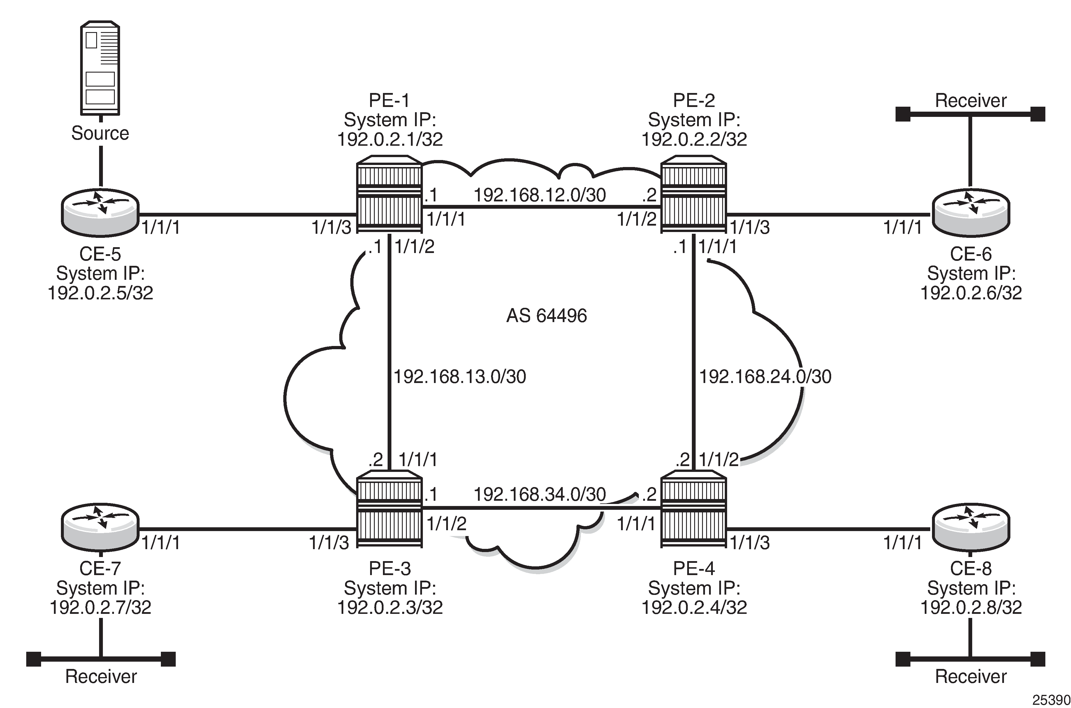
When the receiver wishes to become a member of any group, the source address of the group must be known to the CE. As a result, the source address must be IP reachable by each CE, so it is advertised using BGP by CE-5 to the PEs with attachment circuits in the VPRN. Static routes are then configured on the receiver CEs to achieve IP reachability to the source address of the multicast group.
Multicast traffic from the source is streamed toward router CE-5. Receivers connected to PE-2, PE-3 and PE-4 are interested in joining this multicast group.
CEs 5 to 8 are PIM enabled routers, which form a PIM adjacency with their nearest PE. Between the PEs across the provider network, there are no PIM adjacencies, because BGP auto-discovery and BGP signaling are used. Selective PMSI using mLDP or RSVP P2MP are out of the scope of this chapter. Selective PMSI using PIM SSM is supported too. I-PMSI and S-PMSI must use the same tunneling technology, either PIM/GRE, or mLDP, or RSVP P2MP.
Configuration
The configuration is divided into the following sections:
Provider common configuration
PE global configuration
PE VPRN configuration and PE VPRN multicast configuration for NG-MVPN
PMSI using mLDP
PMSI using RSVP-TE
UMH (upstream multicast hop)
PE VPRN configuration and PE VPRN multicast configuration for Rosen MVPN using MDT AFI SAFI
Auto discovery using BGP MDT AFI SAFI as per Rosen MVPN version 9 with MDT using PIM SSM
Provider Common Configuration
PE Global Configuration
This section describes the common configuration required for each PE within the provider multicast domain, regardless of the MVPN PE auto-discovery or customer signaling methods. This includes interior gateway protocol (IGP) and VPRN service configuration.
The configuration tasks can be summarized as follows:
PE global configuration.
This includes configuration of the IGP (IS-IS will be used); configuration of link layer LDP between PEs (LDP will be used here as the method to interconnect VPRNs); configuration of iBGP between PEs to facilitate VPRN route learning.
VPRN configuration on the PEs.
This includes configuration of basic VPRN parameters (route-distinguisher, route target communities), configuration of attachment circuits toward CEs, configuration of VRF routing protocol and any routing policies.
PIM within the VRF and MVPN parameters — I-PMSI
CE configuration.
Step 1.
Configure the interfaces, the IGP (IS-IS) in all PE nodes (where IS-IS redistributes route reachability to all routers) and LDP in the interfaces (link layer LDP). To facilitate the IS-IS configuration, all routers are Level2-Level1 capable within the same ISIS area-id, so there is only a single topology area in the network (all routers share the same topology). The configuration for PE-1 is displayed below.
# on PE-1
configure
    router
        interface "int-PE-1-PE-2"
            address 192.168.12.1/30
            port 1/1/1
            no shutdown
        exit
        interface "int-PE-1-PE-3"
            address 192.168.13.1/30
            port 1/1/2
            no shutdown
        exit
        interface "system"
            address 192.0.2.1/32
            no shutdown
        exit
        autonomous-system 64496
        isis 0
            area-id 49.0001
            traffic-engineering
            interface "system"
                passive
                no shutdown
            exit
            interface "int-PE-1-PE-2"
                interface-type point-to-point
                no shutdown
            exit
            interface "int-PE-1-PE-3"
                interface-type point-to-point
                no shutdown
            exit
            no shutdown
        exit
        ldp
            interface-parameters
                interface "int-PE-1-PE-2" dual-stack
                exit
                interface "int-PE-1-PE-3" dual-stack
                exit
            exit
        exit
    exit
exit
The configuration for the rest of nodes is similar. The IP addresses can be derived from Network Topology.
Step 2.
Verify that IS-IS adjacencies and LDP peer sessions are formed.
*A:PE-1# show router isis adjacency

===============================================================================
Rtr Base ISIS Instance 0 Adjacency
===============================================================================
System ID                Usage State Hold Interface                     MT-ID
-------------------------------------------------------------------------------
PE-2                     L1L2  Up    22   int-PE-1-PE-2                 0
PE-3                     L1L2  Up    22   int-PE-1-PE-3                 0
-------------------------------------------------------------------------------
Adjacencies : 2
===============================================================================
*A:PE-1#
*A:PE-1# show router ldp session ipv4

==============================================================================
LDP IPv4 Sessions
==============================================================================
Peer LDP Id         Adj Type  State         Msg Sent  Msg Recv  Up Time
------------------------------------------------------------------------------
192.0.2.2:0         Link      Established   21        22        0d 00:00:33
192.0.2.3:0         Link      Established   19        20        0d 00:00:24
------------------------------------------------------------------------------
No. of IPv4 Sessions: 2
==============================================================================
*A:PE-1#
Step 3.
Configure iBGP full mesh between the PEs for VPRN routing (Route Reflectors could also be an option).
# on PE-1
configure
    router
        bgp
            min-route-advertisement 1
            rapid-withdrawal
            rapid-update mvpn-ipv4 mdt-safi
            group "INTERNAL"
                family vpn-ipv4 mvpn-ipv4 mdt-safi
                type internal
                neighbor 192.0.2.2
                exit
                neighbor 192.0.2.3
                exit
                neighbor 192.0.2.4
                exit
            exit
            no shutdown
        exit
The families configured under the group ‟INTERNAL” are vpn-ipv4, mvpn-ipv4, and mdt-safi, since the three families are referenced in this chapter.
The mdt-safi parameter is not needed for NG-MVPN (mLDP/RSVP scenarios) and is only required for Rosen MVPN with MDT AFI SAFI.
Rapid withdrawal (configured on all PEs) disables the minimum route advertisement interval (MRAI) interval on sending BGP withdrawals. Rapid update (configured for MVPN-IPv4 and MDT AFI/SAFI address families) disables the MRAI interval on sending BGP update messages for the address family MVPN-IPv4 and MDT-SAFI).
Step 4.
Verify that BGP peer relationships are established.
*A:PE-1# show router bgp summary
===============================================================================
 BGP Router ID:192.0.2.1        AS:64496       Local AS:64496
===============================================================================
BGP Admin State         : Up          BGP Oper State              : Up
Total Peer Groups       : 1           Total Peers                 : 3
Total VPN Peer Groups   : 0           Total VPN Peers             : 0
Total BGP Paths         : 15          Total Path Memory           : 3960

Total IPv4 Remote Rts   : 0           Total IPv4 Rem. Active Rts  : 0
Total IPv6 Remote Rts   : 0           Total IPv6 Rem. Active Rts  : 0

---snip---

===============================================================================
BGP Summary
===============================================================================
Legend : D - Dynamic Neighbor
===============================================================================
Neighbor
Description
                   AS PktRcvd InQ  Up/Down   State|Rcv/Act/Sent (Addr Family)
                      PktSent OutQ
-------------------------------------------------------------------------------
192.0.2.2
               64496        4    0 00h00m55s 0/0/0 (VpnIPv4)
                            4    0           0/0/0 (MvpnIPv4)
                                             0/0/0 (MdtSafi)
192.0.2.3
               64496        4    0 00h00m46s 0/0/0 (VpnIPv4)
                            4    0           0/0/0 (MvpnIPv4)
                                             0/0/0 (MdtSafi)
192.0.2.4
               64496        4    0 00h00m38s 0/0/0 (VpnIPv4)
                            4    0           0/0/0 (MvpnIPv4)
                                             0/0/0 (MdtSafi)
-------------------------------------------------------------------------------
*A:PE-1#
PE VPRN Configuration and PE VPRN Multicast Configuration
A VPRN is created on each PE per service (the different services using mLDP, RSVP-TE, and AFI/SAFI with PIM); these are the multicast VPRNs. PE-1 is the PE containing the attachment circuit toward CE-5. CE-5 is the CE nearest to the source. PE-2, PE-3, and PE-4 contain attachment circuits toward CE-6, CE-7, and CE-8 respectively. Each CE has a receiving host attached.
PMSI using mLDP
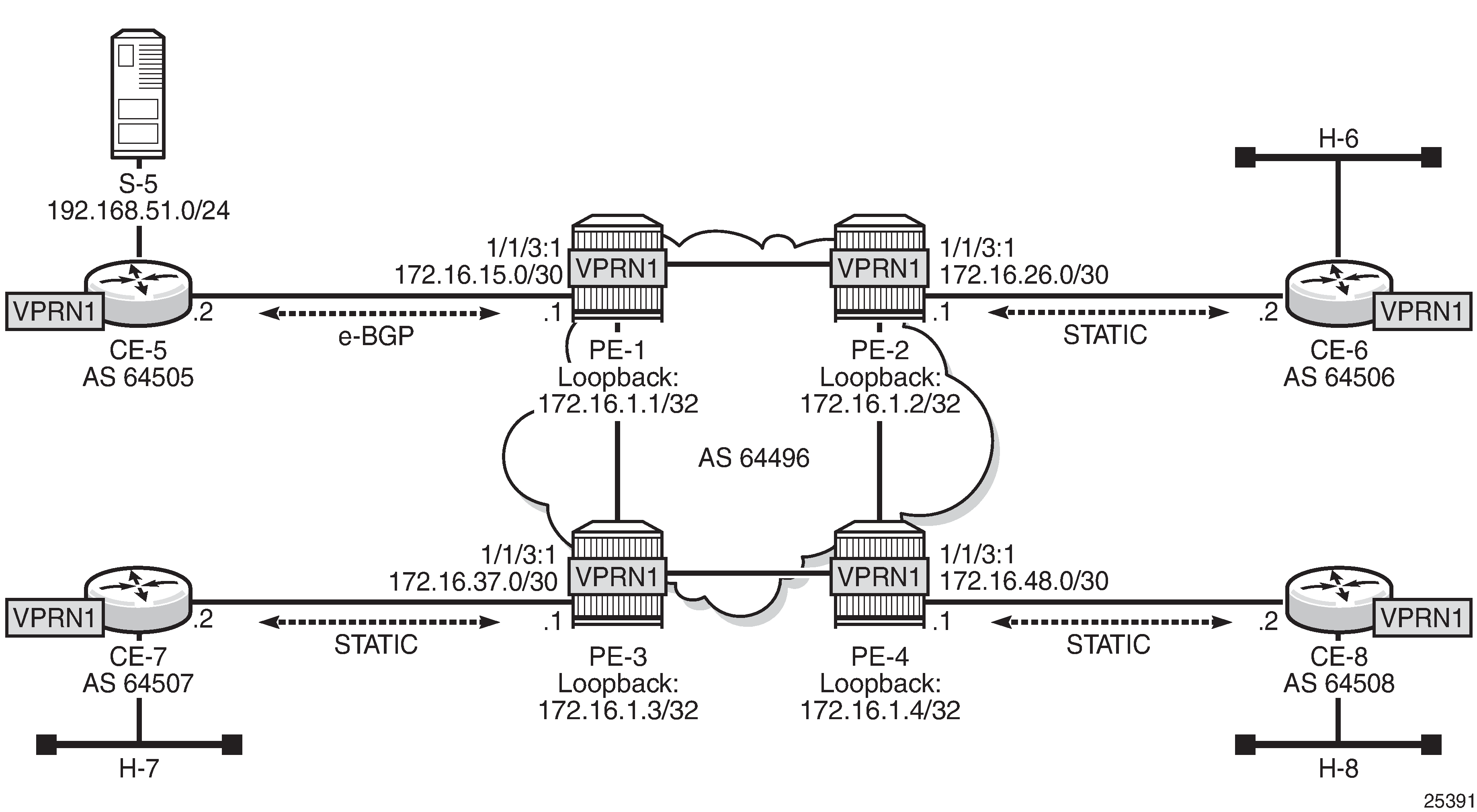
VPRN 1 Topology used for mLDP shows the details of the topology for VPRN 1.
Unicast
Step 1.
Create VPRN 1 on each PE, containing a route-distinguisher of 64496:10X (where X= number of PE) and vrf-target of 64496:100. The autonomous system number is 64496. For the next hop tunnel route resolution to connect the VPRNs between the PEs, manually configured spoke SDPs are created (other methods such as auto-bind-tunnel resolution-filter LDP resolution filter could also be used). LDP was already enabled.
# on PE-1
configure
    service
        sdp 12 mpls create
            far-end 192.0.2.2
            ldp
            no shutdown
        exit
        sdp 13 mpls create
            far-end 192.0.2.3
            ldp
            no shutdown
        exit
        sdp 14 mpls create
            far-end 192.0.2.4
            ldp
            no shutdown
        exit
        vprn 1 customer 1 create
            description "mLDP"
            autonomous-system 64496
            route-distinguisher 64496:101
            vrf-target target:64496:100
            spoke-sdp 12 create
            exit
            spoke-sdp 13 create
            exit
            spoke-sdp 14 create
            exit
Step 2.
Create an attachment circuit interface toward the CE and a loopback (the loopback is not mandatory, but it is configured to aid troubleshooting the routers).
# on PE-1
configure
    service
        vprn 1
            interface "loopback" create
                address 172.16.1.1/32
                loopback
            exit
            interface "int-PE-1-CE-5" create
                address 172.16.15.1/30
                sap 1/1/3:1 create
                exit
            exit
Step 3.
The source address of the multicast stream will need to be reachable by all routers (PEs and CEs) within the VPN. This will be advertised within BGP from CE-5 to PE-1. Create a BGP peering relationship with the CE as follows:
# on PE-1
configure
    service
        vprn 1
            bgp
                group "EXTERNAL"
                    type external
                    peer-as 64505
                    neighbor 172.16.15.2
                    exit
                exit
                no shutdown
            exit
Step 4.
On CE-5, create a VPRN to support the connection of the source to CE-5 and the connection from CE-5 to PE-1. Two attachment circuits are required as well as a BGP peering relationship with the PE. This uses a default BGP address family of ipv4.
# on CE-5
configure
    service
        vprn 1 customer 1 create
            autonomous-system 64505
            route-distinguisher 64505:1
            interface "int-CE-5-PE-1" create
                address 172.16.15.2/30
                sap 1/1/1:1 create
                exit
            exit
            interface "int-CE-5-S-5" create
                address 192.168.51.1/24
                sap 1/1/3 create
                exit
            exit
            bgp
                group "EXTERNAL"
                    type external
                    peer-as 64496
                    neighbor 172.16.15.1
                    exit
                exit
                no shutdown
            exit
            no shutdown
        exit
Step 5.
In order for the subnet on the CE connecting to the source to be advertised within BGP, a route policy is required. The subnet containing the multicast source is 192.168.51.0/24, so a prefix-list can be used to define a match, and then used within a route policy to inject into BGP.
# on CE-5
configure
    router
        policy-options
            begin
            prefix-list "SOURCE-PREFIX"
                prefix 192.168.51.0/24 exact
            exit
            policy-statement "EXPORT-SOURCE-PREFIX-TO-BGP"
                entry 10
                    from
                        prefix-list "SOURCE-PREFIX"
                    exit
                    to
                        protocol bgp
                    exit
                    action accept
                    exit
                exit
            exit
            commit
        exit
configure
    service
        vprn 1
            bgp
                export "EXPORT-SOURCE-PREFIX-TO-BGP"
            exit
        exit
Step 6.
Check that the route is seen in PE-1:
*A:PE-1# show router 1 route-table 192.168.51.0/24

===============================================================================
Route Table (Service: 1)
===============================================================================
Dest Prefix[Flags]                            Type    Proto     Age        Pref
      Next Hop[Interface Name]                                    Metric
-------------------------------------------------------------------------------
192.168.51.0/24                               Remote  BGP       00h01m29s  170
       172.16.15.2                                                  0
-------------------------------------------------------------------------------
No. of Routes: 1
Flags: n = Number of times nexthop is repeated
       B = BGP backup route available
       L = LFA nexthop available
       S = Sticky ECMP requested
===============================================================================
*A:PE-1#
This prefix will also be automatically advertised within the BGP VPRN to all other PEs, and will be installed in VRF 1.
For example, on PE-4, the source subnet 192.168.51.0/24 is received via BGP VPN with a next-hop of PE-1 (192.0.2.1):
*A:PE-4# show router 1 route-table 192.168.51.0/24

===============================================================================
Route Table (Service: 1)
===============================================================================
Dest Prefix[Flags]                            Type    Proto     Age        Pref
      Next Hop[Interface Name]                                    Metric
-------------------------------------------------------------------------------
192.168.51.0/24                               Remote  BGP VPN   00h01m40s  170
       192.0.2.1 (tunneled)                                         0
-------------------------------------------------------------------------------
No. of Routes: 1
Flags: n = Number of times nexthop is repeated
       B = BGP backup route available
       L = LFA nexthop available
       S = Sticky ECMP requested
===============================================================================
*A:PE-4#
Each CE containing a multicast receiver must be able to reach the source. As an example on CE-6, a static route is configured with next hop 172.16.26.1 of interface int-PE-2-CE-6.
# on CE-6
configure
    service
        vprn 1 customer 1 create
            autonomous-system 64506
            route-distinguisher 64506:1
            interface int-CE-6-H-6 create
                address 192.168.61.1/24
                sap 1/1/2:1 create
                exit
            exit
            interface int-CE-6-PE-2 create
                address 172.16.26.2/30
                sap 1/1/1:1 create
                exit
            exit
            static-route-entry 192.168.51.0/24
                next-hop 172.16.26.1
                    no shutdown
                exit
            exit
            no shutdown
        ---snip---
After Steps 1 to 6, all required unicast routing is provisioned. The following sections show the configuration of the multicast in the VPRN.
Auto-Discovery and mLDP PMSI Establishment
The MP-BGP based auto-discovery is implemented with a dedicated address family defined in RFC 4760 MP_REACH_NLRI/MP_UNREACH_NLRI attributes, with AFI 1 (IPv4) or 2 (IPv6) SAFI 5 (temporary value assigned by IANA). This is the mechanism by which each PE advertises the presence of an MVPN to other PEs. This can be achieved using PIM (like in Rosen MVPN) or using BGP. With the default parameter, BGP is automatically chosen because the PMSIs are mLDP and PIM is not an option in this case. Any PE that is a member of an MVPN will advertise to the other PEs using a BGP multi-protocol network layer reachability information (NLRI) update that is sent to all PEs within the AS. This update will contain an Intra-AS I-PMSI auto-discovery route type, also known as an Intra-AD. These use an address family mvpn-ipv4, so each PE must be configured to originate and accept such updates (this was done earlier when configuring the families).
At this step (auto-discovery), the information about the PMSI is exchanged, but the PMSI is not instantiated.
As each PE contains a CE which will be part of the multicast VRF, it is necessary to enable PIM on each interface containing the attachment circuit toward a CE, and to configure the I-PMSI multicast tunnel for the VRF. In order for the BGP routes to be accepted into the VRF, a route-target community is required (vrf-target). This is configured in the configure service vprn 1 mvpn context and, in this case is set to the same value as the unicast vrf-target (the vrf-target community as the configure service vprn 1 vrf-target context).
On each PE, the PIM and MVPN context within the VPRN instance are configured as follows:
# on PE-4
configure
    service
        vprn 1
            pim
                interface "loopback"
                exit
                interface "int-PE-4-CE-8"
                exit
            exit
            mvpn
                auto-discovery default
                c-mcast-signaling bgp
                provider-tunnel
                    inclusive
                        mldp
                            no shutdown
                        exit
                    exit
                exit
                vrf-target unicast
                exit
When PIM SSM is used, the configuration always shows RP static with no RP entries (this is enabled by default when PIM is provisioned). In order for the BGP routes to be accepted into the VRF, a route-target community is required (vrf-target). Although it is not mandatory for the mvpn target to be equal to the unicast target, Nokia recommends to use vrf-target unicast to avoid configuration mistakes and extra complexity.
The status of VPRN 1 on PE-1 is shown with the following output:
*A:PE-1# show router 1 mvpn

===============================================================================
MVPN 1 configuration data
===============================================================================
signaling          : Bgp                  auto-discovery     : Default
UMH Selection      : Highest-Ip           SA withdrawn       : Disabled
intersite-shared   : Enabled              Persist SA         : Disabled
vrf-import         : N/A
vrf-export         : N/A
vrf-target         : unicast
C-Mcast Import RT  : target:192.0.2.1:2

ipmsi              : ldp
i-pmsi P2MP AdmSt  : Up
i-pmsi Tunnel Name : mpls-if-73728
Mdt-type           : sender-receiver

BSR signalling     : none
Wildcard s-pmsi    : Disabled
Multistream-SPMSI  : Disabled
s-pmsi             : none
data-delay-interval: 3 seconds
enable-asm-mdt     : N/A

===============================================================================
*A:PE-1#
The following shows a debug of an Intra-AD BGP update message received by PE-1 that was sent by PE-2. The message contains the PMSI tunnel type to be used (LDP P2MP LSP), LSP identification (root node, opaque value) and the type of BGP update (Type: Intra-AD Len: 12 RD: 64496:102 Orig: 192.0.2.2):
11 2017/10/07 18:31:59.676 UTC MINOR: DEBUG #2001 Base Peer 1: 192.0.2.2
"Peer 1: 192.0.2.2: UPDATE
Peer 1: 192.0.2.2 - Received BGP UPDATE:
    Withdrawn Length = 0
    Total Path Attr Length = 91
    Flag: 0x90 Type: 14 Len: 23 Multiprotocol Reachable NLRI:
        Address Family MVPN_IPV4
        NextHop len 4 NextHop 192.0.2.2
        Type: Intra-AD Len: 12 RD: 64496:102 Orig: 192.0.2.2
    Flag: 0x40 Type: 1 Len: 1 Origin: 0
    Flag: 0x40 Type: 2 Len: 0 AS Path:
    Flag: 0x80 Type: 4 Len: 4 MED: 0
    Flag: 0x40 Type: 5 Len: 4 Local Preference: 100
    Flag: 0xc0 Type: 8 Len: 4 Community:
        no-export
    Flag: 0xc0 Type: 16 Len: 8 Extended Community:
        target:64496:100
    Flag: 0xc0 Type: 22 Len: 22 PMSI:
        Tunnel-type LDP P2MP LSP (2)
        Flags: (0x0)[Type: None BM: 0 U: 0 Leaf: not required]
        MPLS Label 0
        Root-Node 192.0.2.2, LSP-ID 0x2001
The setup has four PEs, so every PE should see the Intra-AD routes from its peers; the following output shows the routes received in PE-1:
*A:PE-1# show router bgp routes mvpn-ipv4 type intra-ad
===============================================================================
 BGP Router ID:192.0.2.1        AS:64496       Local AS:64496
===============================================================================
 Legend -
 Status codes  : u - used, s - suppressed, h - history, d - decayed, * - valid
                 l - leaked, x - stale, > - best, b - backup, p - purge
 Origin codes  : i - IGP, e - EGP, ? - incomplete

===============================================================================
BGP MVPN-IPv4 Routes
===============================================================================
Flag  RouteType                   OriginatorIP           LocalPref   MED
      RD                          SourceAS               Path-Id     Label
      Nexthop                     SourceIP
      As-Path                     GroupIP
-------------------------------------------------------------------------------
u*>i  Intra-Ad                    192.0.2.2              100         0
      64496:102                   -                      None        -
      192.0.2.2                   -
      No As-Path                  -
u*>i  Intra-Ad                    192.0.2.3              100         0
      64496:103                   -                      None        -
      192.0.2.3                   -
      No As-Path                  -
u*>i  Intra-Ad                    192.0.2.4              100         0
      64496:104                   -                      None        -
      192.0.2.4                   -
      No As-Path                  -
-------------------------------------------------------------------------------
Routes : 3
===============================================================================
*A:PE-1#
The detailed output of the Intra-AD received from PE-2 shows the Tunnel-Type LDP P2MP LSP (LSP-ID is 8193), the originator id (192.0.2.2), and the route-distinguisher (64496:102):
*A:PE-1# show router bgp routes mvpn-ipv4 type intra-ad detail
===============================================================================
 BGP Router ID:192.0.2.1        AS:64496       Local AS:64496
===============================================================================
 Legend -
 Status codes  : u - used, s - suppressed, h - history, d - decayed, * - valid
                 l - leaked, x - stale, > - best, b - backup, p - purge
 Origin codes  : i - IGP, e - EGP, ? - incomplete

===============================================================================
BGP MVPN-IPv4 Routes
===============================================================================
Original Attributes

Route Type     : Intra-Ad
Route Dist.    : 64496:102
Originator IP  : 192.0.2.2
Nexthop        : 192.0.2.2
Path Id        : None
From           : 192.0.2.2
Res. Nexthop   : 0.0.0.0
Local Pref.    : 100                    Interface Name : NotAvailable
Aggregator AS  : None                   Aggregator     : None
Atomic Aggr.   : Not Atomic             MED            : 0
AIGP Metric    : None
Connector      : None
Community      : no-export target:64496:100
Cluster        : No Cluster Members
Originator Id  : None                   Peer Router Id : 192.0.2.2
Flags          : Used  Valid  Best  IGP
Route Source   : Internal
AS-Path        : No As-Path
Route Tag      : 0
Neighbor-AS    : N/A
Orig Validation: N/A
Source Class   : 0                      Dest Class     : 0
Add Paths Send : Default
Last Modified  : 00h01m47s
VPRN Imported  :  1
-------------------------------------------------------------------------------
PMSI Tunnel Attributes :
Tunnel-type    : LDP P2MP LSP
Flags          : Type: RNVE(0) BM: 0 U: 0 Leaf: not required
MPLS Label     : 0
Root-Node      : 192.0.2.2              LSP-ID         : 8193
-------------------------------------------------------------------------------
---snip---
-------------------------------------------------------------------------------
Routes : 3
===============================================================================
*A:PE-1#
Because of the receiver-driven nature of mLDP, mLDP P2MP LSPs are set up unsolicited from the leaf PEs toward the head-end PE. The leaf PEs discover the head-end PE via I-PMSI/S-PMSI AD routes. The tunnel identifier carried in the PMSI attribute is used as the P2MP forwarding equivalence class (FEC) Element. The tunnel identifier consists of the address of the head-end PE, along with a generic LSP identifier value. The generic LSP identifier value is automatically generated by the head-end PE. The preceding show command displays the PMSI information with the detail of the root node (192.0.2.2) and the LSP-ID (8193). The PMSI was created after receiving the AD message from PE-2, where the following excerpt from the previous debug shows the same information (0x2001 in HEX is equal to 8193 in decimal).
Flag: 0xc0 Type: 22 Len: 22 PMSI:
        Tunnel-type LDP P2MP LSP (2)
        Flags: (0x0)[Type: None BM: 0 U: 0 Leaf: not required]
        MPLS Label 0
        Root-Node 192.0.2.2, LSP-ID 0x2001
Once the mLDP P2MP LSPs are created, the I-PMSI is instantiated in the core:
*A:PE-1# show router 1 pim neighbor

===============================================================================
PIM Neighbor ipv4
===============================================================================
Interface               Nbr DR Prty     Up Time       Expiry Time     Hold Time
   Nbr Address
-------------------------------------------------------------------------------
int-PE-1-CE-5           1               0d 00:02:28   0d 00:01:43     105
   172.16.15.2
mpls-if-73729           1               0d 00:02:18   never           65535
   192.0.2.2
mpls-if-73730           1               0d 00:02:08   never           65535
   192.0.2.3
mpls-if-73731           1               0d 00:01:58   never           65535
   192.0.2.4
-------------------------------------------------------------------------------
Neighbors : 4
===============================================================================
*A:PE-1#
*A:PE-1# show router 1 pim tunnel-interface

===============================================================================
PIM Interfaces ipv4
===============================================================================
Interface                        Originator Address   Adm  Opr  Transport Type
-------------------------------------------------------------------------------
mpls-if-73728                    192.0.2.1            Up   Up   Tx-IPMSI
mpls-if-73729                    192.0.2.2            Up   Up   Rx-IPMSI
mpls-if-73730                    192.0.2.3            Up   Up   Rx-IPMSI
mpls-if-73731                    192.0.2.4            Up   Up   Rx-IPMSI
-------------------------------------------------------------------------------
Interfaces : 4
===============================================================================
*A:PE-1#
Every PE has created an I-PMSI to the other PEs. Checking the mLDP P2MP LSPs that are originated, transit, or destination to PE-1:
*A:PE-1# show router ldp bindings active p2mp ipv4

===============================================================================
LDP Bindings (IPv4 LSR ID 192.0.2.1)
             (IPv6 LSR ID ::)
===============================================================================
Label Status:
        U - Label In Use, N - Label Not In Use, W - Label Withdrawn
        WP - Label Withdraw Pending, BU - Alternate For Fast Re-Route
        e - Label ELC
FEC Flags:
        LF - Lower FEC, UF - Upper FEC, M - Community Mismatch, BA - ASBR Backup FEC
===============================================================================
LDP Generic IPv4 P2MP Bindings (Active)
===============================================================================
P2MP-Id                                     Interface
RootAddr                                    Op              IngLbl    EgrLbl
EgrNH                                       EgrIf/LspId
-------------------------------------------------------------------------------
8193                                        73728
192.0.2.1                                   Push              --      262138
192.168.12.2                                1/1/1

8193                                        73728
192.0.2.1                                   Push              --      262138
192.168.13.2                                1/1/2

8193                                        73729
192.0.2.2                                   Pop             262138      --
  --                                          --

8193                                        73729
192.0.2.2                                   Swap            262138    262137
192.168.13.2                                1/1/2

8193                                        73730
192.0.2.3                                   Pop             262137      --
  --                                          --

8193                                        73730
192.0.2.3                                   Swap            262137    262137
192.168.12.2                                1/1/1

8193                                        73731
192.0.2.4                                   Pop             262136      --
  --                                          --

-------------------------------------------------------------------------------
No. of Generic IPv4 P2MP Active Bindings: 7
===============================================================================
---snip---
*A:PE-1#
The two first entries in the output show the P2MP LSP where PE-1 is the root head-end (Push). The other two entries (Swap and Pop) correspond with transit and leaf for the P2MP LSPs originated by the other PEs. The command shows a P2MP-ID (8193) with an interface 73728 (matches with the show router 1 pim tunnel interface being the PIM interface created from PE-1) with two egress interfaces pointing to PE-2 and PE-3.
A similar command executed on PE-2 shows:
*A:PE-2# show router ldp bindings active p2mp ipv4
===============================================================================
LDP Bindings (IPv4 LSR ID 192.0.2.2)
             (IPv6 LSR ID ::)
===============================================================================
Label Status:
        U - Label In Use, N - Label Not In Use, W - Label Withdrawn
        WP - Label Withdraw Pending, BU - Alternate For Fast Re-Route
        e - Label ELC
FEC Flags:
        LF - Lower FEC, UF - Upper FEC, M - Community Mismatch, BA - ASBR Backup FEC
===============================================================================
LDP Generic IPv4 P2MP Bindings (Active)
===============================================================================
P2MP-Id                                     Interface
RootAddr                                    Op              IngLbl    EgrLbl
EgrNH                                       EgrIf/LspId
-------------------------------------------------------------------------------
8193                                        73729
192.0.2.1                                   Pop             262138      --
  --                                          --

8193                                        73729
192.0.2.1                                   Swap            262138    262136
192.168.24.2                                1/1/1

---snip---

-------------------------------------------------------------------------------
No. of Generic IPv4 P2MP Active Bindings: 7
===============================================================================
---snip---
*A:PE-2#
On PE-2, the first entry shows that PE-2 is a leaf of the P2MP LSP tree created by PE-1 (ingress label is 262138 which was the egress label to reach PE-2 and is popped). However, the second entry shows that PE-2 is transit for the P2MP LSP going to PE-4 (ingress label 262138, egress label 262136 next hop PE-4).
The same command on PE-4 shows:
*A:PE-4# show router ldp bindings active p2mp ipv4

===============================================================================
LDP Bindings (IPv4 LSR ID 192.0.2.4)
             (IPv6 LSR ID ::)
===============================================================================
Label Status:
        U - Label In Use, N - Label Not In Use, W - Label Withdrawn
        WP - Label Withdraw Pending, BU - Alternate For Fast Re-Route
        e - Label ELC
FEC Flags:
        LF - Lower FEC, UF - Upper FEC, M - Community Mismatch, BA - ASBR Backup FEC
===============================================================================
LDP Generic IPv4 P2MP Bindings (Active)
===============================================================================
P2MP-Id                                     Interface
RootAddr                                    Op              IngLbl    EgrLbl
EgrNH                                       EgrIf/LspId
-------------------------------------------------------------------------------
8193                                        73731
192.0.2.1                                   Pop             262136      --
  --                                          --

---snip---
-------------------------------------------------------------------------------
No. of Generic IPv4 P2MP Active Bindings: 5
===============================================================================
---snip---
*A:PE-4#
In the first entry, the root is PE-1 and the action is Pop, being the ingress label 262136, showing that this is another leaf for the P2MP LSP started on PE-1.
To complete the information, checking on PE-3, the first entry there is a Pop where the root is PE-1, and the ingress label is 262138:
*A:PE-3# show router ldp bindings active p2mp ipv4

===============================================================================
LDP Bindings (IPv4 LSR ID 192.0.2.3)
             (IPv6 LSR ID ::)
===============================================================================
Label Status:
        U - Label In Use, N - Label Not In Use, W - Label Withdrawn
        WP - Label Withdraw Pending, BU - Alternate For Fast Re-Route
        e - Label ELC
FEC Flags:
        LF - Lower FEC, UF - Upper FEC, M - Community Mismatch, BA - ASBR Backup FEC
===============================================================================
LDP Generic IPv4 P2MP Bindings (Active)
===============================================================================
P2MP-Id                                     Interface
RootAddr                                    Op              IngLbl    EgrLbl
EgrNH                                       EgrIf/LspId
-------------------------------------------------------------------------------
8193                                        73729
192.0.2.1                                   Pop             262138      --
  --                                          --

---snip---

-------------------------------------------------------------------------------
No. of Generic IPv4 P2MP Active Bindings: 5
===============================================================================
---snip---
*A:PE-3#
As a summary, each root PE has a P2MP LSP with three leaves (the other PEs) and they are also transit points to the P2MP LSPs created in the other PEs. As an additional check, an OAM ping can show the different leaves that a P2MP LSP has:
*A:PE-1# oam p2mp-lsp-ping ldp 8193 sender-addr 192.0.2.1 detail
P2MP identifier 8193: | 88 bytes MPLS payload

===============================================================================
Leaf Information
===============================================================================
From             RTT                  Return Code
-------------------------------------------------------------------------------
192.0.2.2        =1.16ms              EgressRtr(3)
192.0.2.3        =1.18ms              EgressRtr(3)
192.0.2.4        =1.84ms              EgressRtr(3)
===============================================================================

Total Leafs responded = 3
          round-trip min/avg/max  = 1.16 / 1.40 / 1.84 ms
Responses based on return code:
EgressRtr(3)=3
*A:PE-1#
An easy way to see the path that the LDP P2MP LSP follows for a specific leaf is the following command (such as LDP trace from PE-1 to PE-4):
*A:PE-1# oam ldp-treetrace prefix 192.0.2.4/32

ldp-treetrace for Prefix 192.0.2.4/32:

      192.168.24.2, ttl =   2 dst =      127.1.0.255 rc = EgressRtr status = Done
    Hops:      192.168.12.2

ldp-treetrace discovery state: Done
ldp-treetrace discovery status: ' OK '
Total number of discovered paths: 1
Total number of failed traces: 0

*A:PE-1#
The command shows that on PE-4, there is an active leaf of the P2MP LSP, and that there is an intermediate hop on PE-2.
Traffic Flow
The receiver H-8, connected to CE-8, wishes to join the group 232.1.1.1 with source 192.168.51.1 and sends an IGMPv3 report toward CE-8. CE-8 recognizes the report and sends a PIM join toward the source, therefore, it reaches PE-1 where the source is connected to through CE-5. The following output shows the debug seen on PE-4, where the PIM join is received from CE-8 and a BGP update Source Join is sent to all PEs (only the update sent to PE-1 is shown).
17 2017/10/07 18:38:05.446 UTC MINOR: DEBUG #2001 vprn1 PIM[vprn 2 vprn1]
"PIM[vprn 2 vprn1]: pimJPProcessSG
pimJPProcessSG: (S,G)-> (192.168.51.2,232.1.1.1) type <S,G>, i/f int-PE-4-CE-8,
upNbr 172.16.48.1 isJoin 1 isRpt 0 holdTime 210"

18 2017/10/07 18:38:05.446 UTC MINOR: DEBUG #2001 vprn1 PIM[vprn 2 vprn1]
"PIM[vprn 2 vprn1]: pimRtmFindRpfNexthop
Track (192.168.51.2,232.1.1.1) type <S,G> using 192.168.51.2"

19 2017/10/07 18:38:05.446 UTC MINOR: DEBUG #2001 vprn1 PIM[vprn 2 vprn1]
"PIM[vprn 2 vprn1]: pimRtmAddSrcEntry
Added src entry for src 192.168.51.2"

20 2017/10/07 18:38:05.446 UTC MINOR: DEBUG #2001 vprn1 PIM[vprn 2 vprn1]
"PIM[vprn 2 vprn1]: pimJPPrintFsmEvent
PIM JP Downstream: State NoInfo Event RxJoin StandbyEvent F, (S,G)
 (192.168.51.2,232.1.1.1) groupType <S,G>"

21 2017/10/07 18:38:05.446 UTC MINOR: DEBUG #2001 vprn1 PIM[vprn 2 vprn1]
"PIM[vprn 2 vprn1]: pimJPPrintFsmEvent
PIM JP Upstream: State NotJoined Event JoinDesiredTrue StandbyEvent F, (S,G)
 (192.168.51.2,232.1.1.1) groupType <S,G>"

22 2017/10/07 18:38:05.446 UTC MINOR: DEBUG #2001 vprn1 PIM[vprn 2 vprn1]
"PIM[vprn 2 vprn1]: pimSGUpJoinDesiredTrue
No upstream interface. pSG (192.168.51.2,232.1.1.1) rpfType 3"

23 2017/10/07 18:38:05.446 UTC MINOR: DEBUG #2001 vprn1 PIM[vprn 2 vprn1]
"PIM[vprn 2 vprn1]: pimSGUpJoinDesiredTrue
No upstream interface SG (192.168.51.2,232.1.1.1) rpfType 3"

24 2017/10/07 18:38:05.446 UTC MINOR: DEBUG #2001 vprn1 PIM[vprn 2 vprn1]
"PIM[vprn 2 vprn1]: pimRtmProcessNhresEvent
RTM-Nhres Event U-RTM NEW Src 192.168.51.2 SrcRtmUse UCAST"

25 2017/10/07 18:38:05.446 UTC MINOR: DEBUG #2001 vprn1 PIM[vprn 2 vprn1]
"PIM[vprn 2 vprn1]: pimRtmProcessNhresEvent
Prefix 192.168.51.0/24 numNextHops 1 owner BGP_VPN metric 20 pref 170"

26 2017/10/07 18:38:05.446 UTC MINOR: DEBUG #2001 vprn1 PIM[vprn 2 vprn1]
"PIM[vprn 2 vprn1]: pimRtmSrcResolveSGsInt
Trying to resolve SG (192.168.51.2,232.1.1.1)"

27 2017/10/07 18:38:05.446 UTC MINOR: DEBUG #2001 vprn1 PIM[vprn 2 vprn1]
"PIM[vprn 2 vprn1]: pimRtmNotifyRpfChange
RPF Change to Source/RP 192.168.51.2  for SG (192.168.51.2,232.1.1.1) dynMLDP F via
 NH 192.0.2.1 IfIdx: 73731 RpfType: REMOTE Reason:  RTE_ADD old NH 0.0.0.0 IfIdx: 0
 RpfType: NONE mplsRpf F NextHops 1 reg 1/1 lfa 0/0"

28 2017/10/07 18:38:05.446 UTC MINOR: DEBUG #2001 vprn1 PIM[vprn 2 vprn1]
"PIM[vprn 2 vprn1]: pimRtmNotifyRpfChange
SG (192.168.51.2,232.1.1.1) Source/RP 192.168.51.2 Ipmsi 73728 NhIf 0 new NhIf 73731"

29 2017/10/07 18:38:05.446 UTC MINOR: DEBUG #2001 vprn1 PIM[vprn 2 vprn1]
"PIM[vprn 2 vprn1]: pimJPPrintFsmEvent
PIM JP Upstream: State Joined Event MribChange StandbyEvent F, (S,G)
 (192.168.51.2,232.1.1.1) groupType <S,G>"

30 2017/10/07 18:38:05.446 UTC MINOR: DEBUG #2001 vprn1 PIM[vprn 2 vprn1]
"PIM[vprn 2 vprn1]: pimSGUpStateJMribChange
SG (192.168.51.2,232.1.1.1), type <S,G> oldMribNhopIp 0.0.0.0 oldRpfNbrIp 0.0.0.0,
 oldRpfType NONE oldRpfIf 0 rptMribNhopIp 0.0.0.0, rptRpfNbrIp 0.0.0.0 rtmReason 48
 isSGExtNet : no"

31 2017/10/07 18:38:05.446 UTC MINOR: DEBUG #2001 vprn1 PIM[vprn 2 vprn1]
"PIM[vprn 2 vprn1]: pimSGUpStateJMribChange
SG (192.168.51.2,232.1.1.1), type <S,G> newMribNhopIp 192.0.2.1 newRpfNbrIp 192.0.2.1
 newRpfType REMOTE newRpfIf 73731"

32 2017/10/07 18:38:05.446 UTC MINOR: DEBUG #2001 vprn1 PIM[vprn 2 vprn1]
"PIM[vprn 2 vprn1]: pimAddToJPTxPdu
pimAddToJPTxPdu: (S,G)-> (192.168.51.2,232.1.1.1), type <S,G>, txPendFlag J isStandby
 F"

33 2017/10/07 18:38:05.446 UTC MINOR: DEBUG #2001 vprn1 PIM[vprn 2 vprn1]
"PIM[vprn 2 vprn1]: pimRtmUpdateSGMetric
SG metric 4294967295 pref 2147483647, new metric 20 pref 170"

---snip---

36 2017/10/07 18:38:05.446 UTC MINOR: DEBUG #2001 Base Peer 1: 192.0.2.1
"Peer 1: 192.0.2.1: UPDATE
Peer 1: 192.0.2.1 - Send BGP UPDATE:
    Withdrawn Length = 0
    Total Path Attr Length = 76
    Flag: 0x90 Type: 14 Len: 33 Multiprotocol Reachable NLRI:
        Address Family MVPN_IPV4
        NextHop len 4 NextHop 192.0.2.4
        Type: Source-Join Len:22 RD: 64496:101 SrcAS: 64496
                                 Src: 192.168.51.2 Grp: 232.1.1.1
    Flag: 0x40 Type: 1 Len: 1 Origin: 0
    Flag: 0x40 Type: 2 Len: 0 AS Path:
    Flag: 0x80 Type: 4 Len: 4 MED: 0
    Flag: 0x40 Type: 5 Len: 4 Local Preference: 100
    Flag: 0xc0 Type: 8 Len: 4 Community:
        no-export
    Flag: 0xc0 Type: 16 Len: 8 Extended Community:
        target:192.0.2.1:2
"
The following debug shows that PE-1 receives the BGP update Source Join with source 192.168.1.1 and group 232.1.1.1 and sends a PIM join toward CE-5:
19 2017/10/07 18:38:05.446 UTC MINOR: DEBUG #2001 Base Peer 1: 192.0.2.4
"Peer 1: 192.0.2.4: UPDATE
Peer 1: 192.0.2.4 - Received BGP UPDATE:
    Withdrawn Length = 0
    Total Path Attr Length = 76
    Flag: 0x90 Type: 14 Len: 33 Multiprotocol Reachable NLRI:
        Address Family MVPN_IPV4
        NextHop len 4 NextHop 192.0.2.4
        Type: Source-Join Len:22 RD: 64496:101 SrcAS: 64496
                                 Src: 192.168.51.2 Grp: 232.1.1.1
    Flag: 0x40 Type: 1 Len: 1 Origin: 0
    Flag: 0x40 Type: 2 Len: 0 AS Path:
    Flag: 0x80 Type: 4 Len: 4 MED: 0
    Flag: 0x40 Type: 5 Len: 4 Local Preference: 100
    Flag: 0xc0 Type: 8 Len: 4 Community:
        no-export
    Flag: 0xc0 Type: 16 Len: 8 Extended Community:
        target:192.0.2.1:2
"

20 2017/10/07 18:38:05.447 UTC MINOR: DEBUG #2001 vprn1 PIM[vprn 2 vprn1]
"PIM[vprn 2 vprn1]: pimProcessMvpnRouteMsg
originator 0.0.0.0: add rtType SOURCE_TREE_JOIN nextHop 192.0.2.4
source 192.168.51.2 group 232.1.1.1"

21 2017/10/07 18:38:05.447 UTC MINOR: DEBUG #2001 vprn1 PIM[vprn 2 vprn1]
"PIM[vprn 2 vprn1]: pimJPProcessSG
pimJPProcessSG: (S,G)-> (192.168.51.2,232.1.1.1) type <S,G>, i/f mpls-if-73728,
upNbr 192.0.2.1 isJoin 1 isRpt 0 holdTime 65535"

22 2017/10/07 18:38:05.447 UTC MINOR: DEBUG #2001 vprn1 PIM[vprn 2 vprn1]
"PIM[vprn 2 vprn1]: pimRtmFindRpfNexthop
Track (192.168.51.2,232.1.1.1) type <S,G> using 192.168.51.2"

23 2017/10/07 18:38:05.447 UTC MINOR: DEBUG #2001 vprn1 PIM[vprn 2 vprn1]
"PIM[vprn 2 vprn1]: pimRtmAddSrcEntry
Added src entry for src 192.168.51.2"

24 2017/10/07 18:38:05.447 UTC MINOR: DEBUG #2001 vprn1 PIM[vprn 2 vprn1]
"PIM[vprn 2 vprn1]: pimJPPrintFsmEvent
PIM JP Downstream: State NoInfo Event RxJoin StandbyEvent F, (S,G)
 (192.168.51.2,232.1.1.1) groupType <S,G>"

25 2017/10/07 18:38:05.447 UTC MINOR: DEBUG #2001 vprn1 PIM[vprn 2 vprn1]
"PIM[vprn 2 vprn1]: pimJPPrintFsmEvent
PIM JP Upstream: State NotJoined Event JoinDesiredTrue StandbyEvent F, (S,G)
 (192.168.51.2,232.1.1.1) groupType <S,G>"

26 2017/10/07 18:38:05.447 UTC MINOR: DEBUG #2001 vprn1 PIM[vprn 2 vprn1]
"PIM[vprn 2 vprn1]: pimAddToJPTxPdu
pimAddToJPTxPdu: (S,G)-> (192.168.51.2,232.1.1.1), type <S,G>,
txPendFlag J isStandby F"

27 2017/10/07 18:38:05.447 UTC MINOR: DEBUG #2001 vprn1 PIM[vprn 2 vprn1]
"PIM[vprn 2 vprn1]: pimRtmProcessNhresEvent
RTM-Nhres Event U-RTM NEW Src 192.168.51.2 SrcRtmUse UCAST"

28 2017/10/07 18:38:05.447 UTC MINOR: DEBUG #2001 vprn1 PIM[vprn 2 vprn1]
"PIM[vprn 2 vprn1]: pimRtmProcessNhresEvent
Prefix 192.168.51.0/24 numNextHops 1 owner BGP metric 0 pref 170"

---snip---

37 2017/10/07 18:38:05.447 UTC MINOR: DEBUG #2001 vprn1 PIM[vprn 2 vprn1]
"PIM[vprn 2 vprn1]: pimSGEncodeGroupSet
Encoding  Join for source 192.168.51.2"

38 2017/10/07 18:38:05.447 UTC MINOR: DEBUG #2001 vprn1 PIM[vprn 2 vprn1]
"PIM[vprn 2 vprn1]: pimSGEncodeGroupSet
num joined srcs 1, num pruned srcs 0"

39 2017/10/07 18:38:05.447 UTC MINOR: DEBUG #2001 vprn1 PIM[vprn 2 vprn1]
"PIM[vprn 2 vprn1]: pimSendJoinPrunePdu
sending JP PDU with 1 groups, if 5 adj 172.16.15.2"

40 2017/10/07 18:38:05.447 UTC MINOR: DEBUG #2001 vprn1 PIM[vprn 2 vprn1]
"PIM[vprn 2 vprn1]: pimSendJoinPrunePdu
if 5, adj 172.16.15.2. Nothing to send"
The BGP update source join received by PE-1 is displayed with the command:
*A:PE-1# show router bgp routes mvpn-ipv4 type source-join
===============================================================================
 BGP Router ID:192.0.2.1        AS:64496       Local AS:64496
===============================================================================
 Legend -
 Status codes  : u - used, s - suppressed, h - history, d - decayed, * - valid
                 l - leaked, x - stale, > - best, b - backup, p - purge
 Origin codes  : i - IGP, e - EGP, ? - incomplete

===============================================================================
BGP MVPN-IPv4 Routes
===============================================================================
Flag  RouteType                   OriginatorIP           LocalPref   MED
      RD                          SourceAS               Path-Id     Label
      Nexthop                     SourceIP
      As-Path                     GroupIP
-------------------------------------------------------------------------------
u*>i  Source-Join                 -                      100         0
      64496:101                   64496                  None        -
      192.0.2.4                   192.168.51.2
      No As-Path                  232.1.1.1
-------------------------------------------------------------------------------
Routes : 1
===============================================================================
*A:PE-1#
To verify the traffic: on PE-1 there is a group 232.1.1.1 with source 192.168.51.2, the Reverse Path Forwarding (RPF) is CE-5, the multicast traffic is flowing from CE-5 to PE-1 using int-PE-1-CE-5 and the outgoing interface is using the PMSI mLDP mpls-if-73728.
*A:PE-1# show router 1 pim group detail

===============================================================================
PIM Source Group ipv4
===============================================================================
Group Address      : 232.1.1.1
Source Address     : 192.168.51.2
RP Address         : 0
Advt Router        : 172.16.15.2
Flags              :                    Type               : (S,G)
Mode               : sparse
MRIB Next Hop      : 172.16.15.2
MRIB Src Flags     : remote
Keepalive Timer    : Not Running
Up Time            : 0d 00:00:41        Resolved By        : rtable-u

Up JP State        : Joined             Up JP Expiry       : 0d 00:00:19
Up JP Rpt          : Not Joined StarG   Up JP Rpt Override : 0d 00:00:00

Register State     : No Info
Reg From Anycast RP: No

Rpf Neighbor       : 172.16.15.2
Incoming Intf      : int-PE-1-CE-5
Outgoing Intf List : mpls-if-73728

Curr Fwding Rate   : 1042.6 kbps
Forwarded Packets  : 3582               Discarded Packets  : 0
Forwarded Octets   : 5365836            RPF Mismatches     : 0
Spt threshold      : 0 kbps             ECMP opt threshold : 7
Admin bandwidth    : 1 kbps
-------------------------------------------------------------------------------
Groups : 1
===============================================================================
*A:PE-1#
On PE-4, the same (S,G) arrives in the incoming interface mpls-if-73731 and the outgoing interface is int-PE-4-CE-8.
*A:PE-4# show router 1 pim group detail
===============================================================================
PIM Source Group ipv4
===============================================================================
Group Address      : 232.1.1.1
Source Address     : 192.168.51.2
RP Address         : 0
Advt Router        : 192.0.2.1
Flags              :                    Type               : (S,G)
Mode               : sparse
MRIB Next Hop      : 192.0.2.1
MRIB Src Flags     : remote
Keepalive Timer    : Not Running
Up Time            : 0d 00:00:44        Resolved By        : rtable-u

Up JP State        : Joined             Up JP Expiry       : 0d 00:00:16
Up JP Rpt          : Not Joined StarG   Up JP Rpt Override : 0d 00:00:00

Register State     : No Info
Reg From Anycast RP: No

Rpf Neighbor       : 192.0.2.1
Incoming Intf      : mpls-if-73731
Outgoing Intf List : int-PE-4-CE-8
Curr Fwding Rate   : 1042.6 kbps
Forwarded Packets  : 3785               Discarded Packets  : 0
Forwarded Octets   : 5669930            RPF Mismatches     : 0
Spt threshold      : 0 kbps             ECMP opt threshold : 7
Admin bandwidth    : 1 kbps
-------------------------------------------------------------------------------
Groups : 1
===============================================================================
*A:PE-4#
When the receiver is not interested in the channel group any more, the receiver H-8 sends an IGMPv3 leave, PE-4 sends a PIM prune translated to a BGP MP_UNREACH NLRI to all PEs. As mentioned before, rapid withdrawals are sent without waiting for the MRAI (for simplicity, only one BGP update is shown in the output debug).
41 2017/10/07 18:39:15.413 UTC MINOR: DEBUG #2001 vprn1 PIM[vprn 2 vprn1]
"PIM[vprn 2 vprn1]: pimJPProcessSG
pimJPProcessSG: (S,G)-> (192.168.51.2,232.1.1.1) type <S,G>, i/f int-PE-4-CE-8,
upNbr 172.16.48.1 isJoin 0 isRpt 0 holdTime 210"

42 2017/10/07 18:39:15.413 UTC MINOR: DEBUG #2001 vprn1 PIM[vprn 2 vprn1]
"PIM[vprn 2 vprn1]: pimJPPrintFsmEvent
PIM JP Downstream: State Joined Event RxPrune StandbyEvent F,
(S,G) (192.168.51.2,232.1.1.1) groupType <S,G>"

43 2017/10/07 18:39:15.413 UTC MINOR: DEBUG #2001 vprn1 PIM[vprn 2 vprn1]
"PIM[vprn 2 vprn1]: pimJPPrintFsmEvent
PIM JP Downstream: State PrunePending Event PrunePendTimerExp StandbyEvent F,
(S,G) (192.168.51.2,232.1.1.1) groupType <S,G>"

44 2017/10/07 18:39:15.413 UTC MINOR: DEBUG #2001 vprn1 PIM[vprn 2 vprn1]
"PIM[vprn 2 vprn1]: pimJPPrintFsmEvent
PIM JP Upstream: State Joined Event JoinDesiredFalse StandbyEvent F,
(S,G) (192.168.51.2,232.1.1.1) groupType <S,G>"

45 2017/10/07 18:39:15.413 UTC MINOR: DEBUG #2001 vprn1 PIM[vprn 2 vprn1]
"PIM[vprn 2 vprn1]: pimAddToJPTxPdu
pimAddToJPTxPdu: (S,G)-> (192.168.51.2,232.1.1.1), type <S,G>,
txPendFlag P isStandby F"

46 2017/10/07 18:39:15.413 UTC MINOR: DEBUG #2001 vprn1 PIM[vprn 2 vprn1]
"PIM[vprn 2 vprn1]: pimRtmStopRpfNexthop
Stop tracking (192.168.51.2,232.1.1.1) type <S,G> with 192.168.51.2
pRtmNhop 0x179196078"

47 2017/10/07 18:39:15.413 UTC MINOR: DEBUG #2001 vprn1 PIM[vprn 2 vprn1]
"PIM[vprn 2 vprn1]: pimRtmDelSrcEntry
Deleted src entry for src 192.168.51.2"

48 2017/10/07 18:39:15.413 UTC MINOR: DEBUG #2001 Base Peer 1: 192.0.2.1
"Peer 1: 192.0.2.1: UPDATE
Peer 1: 192.0.2.1 - Send BGP UPDATE:
    Withdrawn Length = 0    Total Path Attr Length = 31
    Flag: 0x90 Type: 15 Len: 27 Multiprotocol Unreachable NLRI:
        Address Family MVPN_IPV4 Type: Source-Join Len:22 RD: 64496:101
        SrcAS: 64496 Src: 192.168.51.2 Grp: 232.1.1.1"
PMSI using RSVP-TE
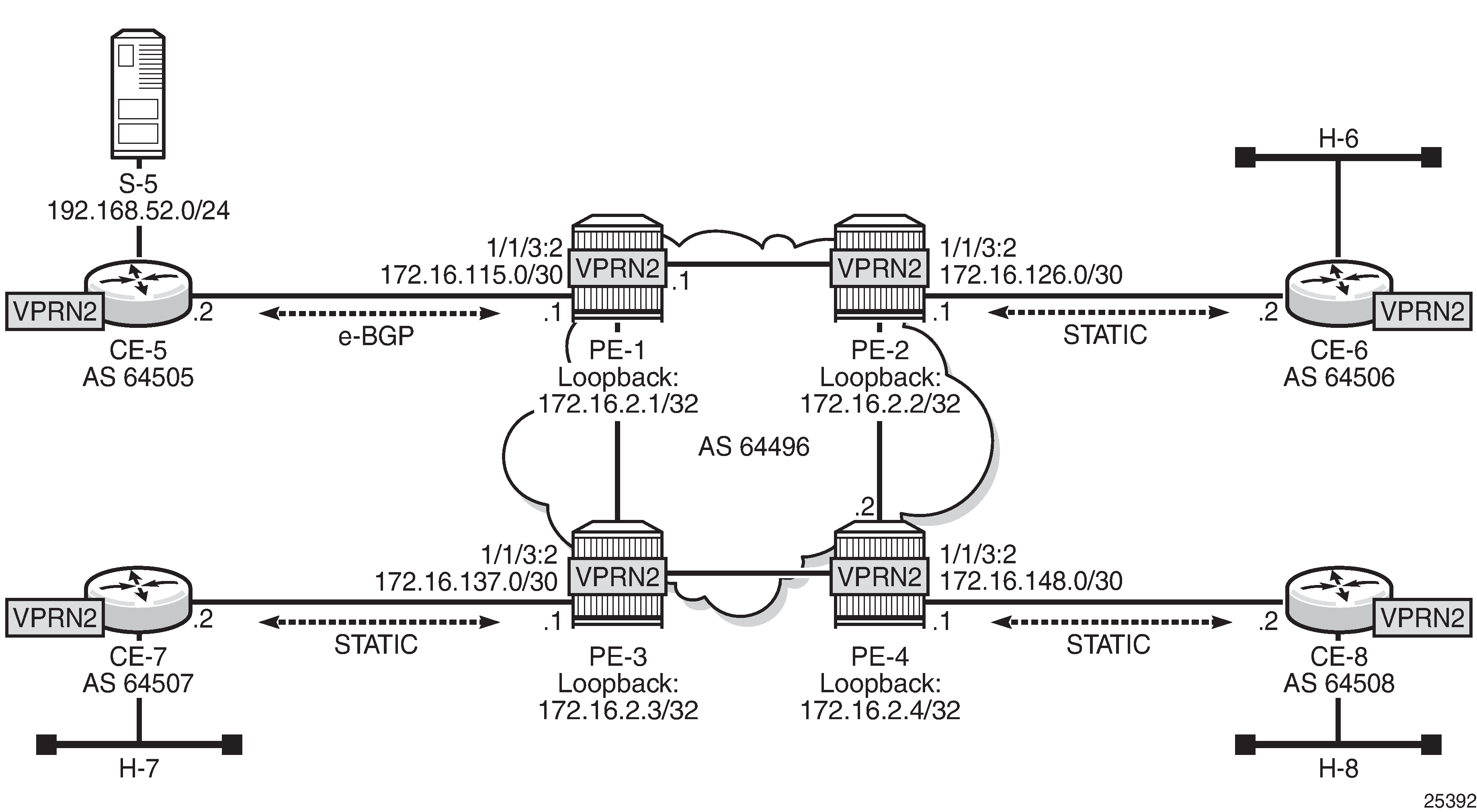
VPRN 2 Topology used for RSVP-TE P2MP shows the details of the topology for VPRN 2.
Unicast
For the sake of simplicity, check Steps 1 to 6 in PMSI using mLDP for VPRN 2 creation information. The same steps are repeated for RSVP, check VPRN 2 Topology used for RSVP-TE P2MP for details. The result is the configuration in all the PEs, taking as an example PE-1:
# on PE-1
configure
    service
        vprn 2 customer 1 create
            description "P2MP RSVP"
            autonomous-system 64496
            route-distinguisher 64496:201
            vrf-target target:64496:200
            interface "loopback" create
                address 172.16.2.1/30
                loopback
            exit
            interface "int-PE-1-CE-5" create
                address 172.16.115.1/30
                sap 1/1/3:2 create
                exit
            exit

            bgp
                group "EXTERNAL"
                    type external
                    peer-as 64505
                    neighbor 172.16.115.2
                    exit
                exit
                no shutdown
            exit
            spoke-sdp 12 create
            exit
            spoke-sdp 13 create
            exit
            spoke-sdp 14 create
            exit
            no shutdown
        exit
Because RSVP is the signaling protocol to establish the P2MP LSPs, RSVP is configured on the interfaces. In addition, to use P2MP RSVP, an LSP template is needed. The template defines the characteristics of the LSP to be created, for example, make-before-break, bandwidth, administrative groups, CSPF, specific paths, etc. A basic template is used here. TE parameters specified in the template are commonly used in each RSVP PATH message for each of the branches of the P2MP RSVP LSP. The template is used in the mvpn context within the VPRN configuration (see Auto-Discovery and RSVP PMSI Establishment). The resignal timer for P2MP is configured to the minimum value of sixty minutes (60 — 10080 minutes):
# on PE-1
configure
    router
        mpls
            p2mp-resignal-timer 60
            interface system
            exit
            interface int-PE-1-PE-2
            exit
            interface int-PE-1-PE-3
            exit
            path EMPTY
                no shutdown
            exit
            lsp-template VRF2 p2mp
                default-path EMPTY
                cspf
                fast-reroute facility
                exit
                no shutdown
            exit
            no shutdown
        exit
    exit
*A:PE-1# configure router rsvp no shutdown
Auto-Discovery and RSVP PMSI Establishment
The MP-BGP based auto-discovery is implemented with a new address family defined in RFC 4760 MP_REACH_NLRI/MP_UNREACH_NLRI attributes, with AFI 1 (IPv4) or 2 (IPv6) SAFI 5 (temporary value assigned by IANA). This is the mechanism by which each PE advertises the presence of an MVPN to other PEs. This can be achieved using PIM (like in Rosen MVPN) or using BGP. With the default parameter, BGP is automatically chosen because the PMSIs are RSVP and PIM is not an option in this case. Any PE that is a member of an MVPN will advertise to the other PEs using a BGP multi-protocol network layer reachability information (NLRI) update that is sent to all PEs within the AS. This update will contain an Intra-AS I-PMSI auto-discovery route type, also known as an Intra-AD. These use an address family mvpn-ipv4, so each PE must be configured to originate and accept such updates (this was done earlier when configuring the families).
At this step (auto-discovery), the information about the PMSI is exchanged, but the PMSI is not instantiated.
As each PE contains a CE which will be part of the multicast VRF, it is necessary to enable PIM on each interface containing the attachment circuit toward a CE, and to configure the I-PMSI multicast tunnel for the VRF. In order for the BGP routes to be accepted into the VRF a route-target community is required (vrf-target). Although it is not mandatory for the MVPN vrf-target to be equal to the unicast target, Nokia recommends to use vrf-target unicast to avoid configuration mistakes and extra complexity.
On each PE, the multicast configuration in the VPRN instance is as follows:
# on PE-1
configure service
        vprn 2
            pim
                interface "loopback"
                exit
                interface "int-PE-1-CE-5"
                exit
            exit
            mvpn
                auto-discovery default
                c-mcast-signaling bgp
                provider-tunnel
                    inclusive
                        rsvp
                            lsp-template "VRF2"
                            no shutdown
                        exit
                    exit
                exit
                vrf-target unicast
                exit
            exit
The status of VPRN 2 on PE-1 is shown with the following output:
*A:PE-1# show router 2 mvpn
===============================================================================
MVPN 2 configuration data
===============================================================================
signaling          : Bgp                  auto-discovery     : Default
UMH Selection      : Highest-Ip           SA withdrawn       : Disabled
intersite-shared   : Enabled              Persist SA         : Disabled
vrf-import         : N/A
vrf-export         : N/A
vrf-target         : unicast
C-Mcast Import RT  : target:192.0.2.1:3

ipmsi              : rsvp VRF2
i-pmsi P2MP AdmSt  : Up
i-pmsi Tunnel Name : VRF2-2-73732
enable-bfd-root    : false                enable-bfd-leaf    : false
Mdt-type           : sender-receiver

BSR signalling     : none
Wildcard s-pmsi    : Disabled
Multistream-SPMSI  : Disabled
s-pmsi             : none
data-delay-interval: 3 seconds
enable-asm-mdt     : N/A
===============================================================================
*A:PE-1#
The following shows a debug of an Intra-AD BGP update message received by PE-1 that was sent by PE-4. The message contains the PMSI tunnel-type to be used (RSVP P2MP LSP), the P2MP LSP ID (encoded as extended tunnel ID and P2MP-ID carried in the RSVP Session object), and the type of BGP update (Type: Intra-AD Len: 12 RD: 64496:204 Orig: 192.0.2.4):
29 2017/10/07 18:47:40.709 UTC MINOR: DEBUG #2001 Base Peer 1: 192.0.2.4
"Peer 1: 192.0.2.4: UPDATE
Peer 1: 192.0.2.4 - Received BGP UPDATE:
    Withdrawn Length = 0
    Total Path Attr Length = 86
    Flag: 0x90 Type: 14 Len: 23 Multiprotocol Reachable NLRI:
        Address Family MVPN_IPV4
        NextHop len 4 NextHop 192.0.2.4
        Type: Intra-AD Len: 12 RD: 64496:204 Orig: 192.0.2.4
    Flag: 0x40 Type: 1 Len: 1 Origin: 0
    Flag: 0x40 Type: 2 Len: 0 AS Path:
    Flag: 0x80 Type: 4 Len: 4 MED: 0
    Flag: 0x40 Type: 5 Len: 4 Local Preference: 100
    Flag: 0xc0 Type: 8 Len: 4 Community:
        no-export
    Flag: 0xc0 Type: 16 Len: 8 Extended Community:
        target:64496:200
    Flag: 0xc0 Type: 22 Len: 17 PMSI:
        Tunnel-type RSVP-TE P2MP LSP (1)
        Flags: (0x0)[Type: None BM: 0 U: 0 Leaf: not required]
        MPLS Label 0
        P2MP-ID 0x2, Tunnel-ID: 61442, Extended-Tunnel-ID 192.0.2.4"
The setup has four PEs, so every PE should see the others peer Intra-AD route; the following output shows the routes received in PE-1:
*A:PE-1# show router bgp routes mvpn-ipv4 type intra-ad
===============================================================================
 BGP Router ID:192.0.2.1        AS:64496       Local AS:64496
===============================================================================
 Legend -
 Status codes  : u - used, s - suppressed, h - history, d - decayed, * - valid
                 l - leaked, x - stale, > - best, b - backup, p - purge
 Origin codes  : i - IGP, e - EGP, ? - incomplete

===============================================================================
BGP MVPN-IPv4 Routes
===============================================================================
Flag  RouteType                   OriginatorIP           LocalPref   MED
      RD                          SourceAS               Path-Id     Label
      Nexthop                     SourceIP
      As-Path                     GroupIP
-------------------------------------------------------------------------------
u*>i  Intra-Ad                    192.0.2.2              100         0
      64496:202                   -                      None        -
      192.0.2.2                   -
      No As-Path                  -
u*>i  Intra-Ad                    192.0.2.3              100         0
      64496:203                   -                      None        -
      192.0.2.3                   -
      No As-Path                  -
u*>i  Intra-Ad                    192.0.2.4              100         0
      64496:204                   -                      None        -
      192.0.2.4                   -
      No As-Path                  -
-------------------------------------------------------------------------------
Routes : 3
===============================================================================
*A:PE-1#
The detailed output of the Intra-AD received from PE-4 shows the tunnel-type RSVP-TE P2MP LSP (P2MP-ID is 2), the originator id (192.0.2.4), and the route-distinguisher (64496:204):
*A:PE-1# show router bgp routes mvpn-ipv4 type intra-ad originator-ip 192.0.2.4 detail
===============================================================================
 BGP Router ID:192.0.2.1        AS:64496       Local AS:64496
===============================================================================
 Legend -
 Status codes  : u - used, s - suppressed, h - history, d - decayed, * - valid
                 l - leaked, x - stale, > - best, b - backup, p - purge
 Origin codes  : i - IGP, e - EGP, ? - incomplete

===============================================================================
BGP MVPN-IPv4 Routes
===============================================================================
Original Attributes

Route Type     : Intra-Ad
Route Dist.    : 64496:204
Originator IP  : 192.0.2.4
Nexthop        : 192.0.2.4
Path Id        : None
From           : 192.0.2.4
Res. Nexthop   : 0.0.0.0
Local Pref.    : 100                    Interface Name : NotAvailable
Aggregator AS  : None                   Aggregator     : None
Atomic Aggr.   : Not Atomic             MED            : 0
AIGP Metric    : None
Connector      : None
Community      : no-export target:64496:200
Cluster        : No Cluster Members
Originator Id  : None                   Peer Router Id : 192.0.2.4
Flags          : Used  Valid  Best  IGP
Route Source   : Internal
AS-Path        : No As-Path
Route Tag      : 0
Neighbor-AS    : N/A
Orig Validation: N/A
Source Class   : 0                      Dest Class     : 0
Add Paths Send : Default
Last Modified  : 00h01m26s
VPRN Imported  :  2
-------------------------------------------------------------------------------
PMSI Tunnel Attributes :
Tunnel-type    : RSVP-TE P2MP LSP
Flags          : Type: RNVE(0) BM: 0 U: 0 Leaf: not required
MPLS Label     : 0
P2MP-ID        : 2                      Tunnel-ID      : 61442
Extended-Tunne*: 192.0.2.4
-------------------------------------------------------------------------------

Modified Attributes

---snip---

-------------------------------------------------------------------------------
Routes : 1
===============================================================================
* indicates that the corresponding row element may have been truncated.
*A:PE-1#
For the I-PMSI, the head-end PE firstly discovers all the leaf PEs via I-PMSI A-D routes, it then signals the P2MP LSP to all the leaf PEs using RSVP-TE (subsequently adding or removing S2L (source to leaf) paths as PEs are added or removed from the MVPN).
As in the mLDP case, the demarcation of the domains is in the PE. The PE router participates in both the customer multicast domain and the provider’s multicast domain. The customer’s CEs are limited to a multicast adjacency with the multicast instance on the PE created to support that specific customer’s IP-VPN. This way, customers are isolated from the provider’s core multicast domain and other customer multicast domains while the provider’s core P routers only participate in the provider’s multicast domain and are isolated from all customers’s multicast domains. C-trees to P-tunnels bindings are also discovered using BGP routes, instead of PIM join TLVs. MVPN c-multicast routing information is exchanged between PEs by using c-multicast routes that are carried using MCAST-VPN NLRIs.
Once the RSVP-TE P2MP LSPs are created, the I-PMSI is instantiated in the core:
*A:PE-1# show router 2 pim neighbor

===============================================================================
PIM Neighbor ipv4
===============================================================================
Interface               Nbr DR Prty     Up Time       Expiry Time     Hold Time
   Nbr Address
-------------------------------------------------------------------------------
int-PE-1-CE-5           1               0d 00:01:23   0d 00:01:24     105
   172.16.115.2
mpls-if-73733           1               0d 00:02:03   never           65535
   192.0.2.2
mpls-if-73734           1               0d 00:01:48   never           65535
   192.0.2.3
mpls-if-73735           1               0d 00:01:38   never           65535
   192.0.2.4
-------------------------------------------------------------------------------
Neighbors : 4
===============================================================================
*A:PE-1#
*A:PE-1# show router 2 pim tunnel-interface

===============================================================================
PIM Interfaces ipv4
===============================================================================
Interface                        Originator Address   Adm  Opr  Transport Type
-------------------------------------------------------------------------------
mpls-if-73732                    192.0.2.1            Up   Up   Tx-IPMSI
mpls-if-73733                    192.0.2.2            Up   Up   Rx-IPMSI
mpls-if-73734                    192.0.2.3            Up   Up   Rx-IPMSI
mpls-if-73735                    192.0.2.4            Up   Up   Rx-IPMSI
-------------------------------------------------------------------------------
Interfaces : 4
===============================================================================
*A:PE-1#
The following command displays the PMSIs created on a PE, taking PE-3 as an example:
*A:PE-3# show router 2 pim tunnel-interface

===============================================================================
PIM Interfaces ipv4
===============================================================================
Interface                        Originator Address   Adm  Opr  Transport Type
-------------------------------------------------------------------------------
mpls-if-73732                    192.0.2.3            Up   Up   Tx-IPMSI
mpls-if-73733                    192.0.2.1            Up   Up   Rx-IPMSI
mpls-if-73734                    192.0.2.2            Up   Up   Rx-IPMSI
mpls-if-73735                    192.0.2.4            Up   Up   Rx-IPMSI
-------------------------------------------------------------------------------
Interfaces : 4
===============================================================================
*A:PE-3#
*A:PE-3# tools dump router 2 mvpn provider-tunnels

===============================================================================
MVPN 2 Inclusive Provider Tunnels Originating
===============================================================================
ipmsi (RSVP)                            P2MP-ID     Tunl-ID     Ext-Tunl-ID
-------------------------------------------------------------------------------
VRF2-2-73732                            2           61441       192.0.2.3

===============================================================================
MVPN 2 Selective Provider Tunnels Originating
===============================================================================
spmsi (RSVP)                            P2MP-ID     Tunl-ID     Ext-Tunl-ID
-------------------------------------------------------------------------------

No Tunnels Found
-------------------------------------------------------------------------------

===============================================================================
MVPN 2 Inclusive Provider Tunnels Terminating
===============================================================================
ipmsi (RSVP)                            P2MP-ID     Tunl-ID     Ext-Tunl-ID
-------------------------------------------------------------------------------
mpls-if-73733                           2           61441       192.0.2.1
mpls-if-73734                           2           61441       192.0.2.2
mpls-if-73735                           2           61442       192.0.2.4

===============================================================================
MVPN 2 Selective Provider Tunnels Terminating
===============================================================================
spmsi (RSVP)                            P2MP-ID     Tunl-ID     Ext-Tunl-ID
-------------------------------------------------------------------------------

No Tunnels Found
-------------------------------------------------------------------------------
*A:PE-3#
Every PE has created an I-PMSI to the other PEs. As an example, PE-1 has established an LSP with name VRF2-2-73732 with PE-2, PE-3 and PE-4 as leaves. The S2L path is empty because the template did not have any S2L path configured for simplicity.
*A:PE-1# show router mpls p2mp-lsp detail

===============================================================================
MPLS P2MP LSPs (Originating) (Detail)
===============================================================================
Legend :
    + - Inherited
===============================================================================
-------------------------------------------------------------------------------
Type : Originating
-------------------------------------------------------------------------------
LSP Name        : VRF2-2-73732
LSP Type        : P2mpAutoLsp               LSP Tunnel ID        : 61441
LSP Index       : 61441                     TTM Tunnel Id        : 61441
From            : 192.0.2.1
Adm State       : Up                        Oper State           : Up
LSP Up Time     : 0d 00:02:59               LSP Down Time        : 0d 00:00:00
Transitions     : 1                         Path Changes         : 1
Retry Limit     : 0                         Retry Timer          : 30 sec
Signaling       : RSVP                      Resv. Style          : SE
Hop Limit       : 255                       Negotiated MTU       : n/a
Adaptive        : Enabled                   ClassType            : 0
FastReroute     : Enabled                   Oper FR              : Enabled
FR Method       : Facility                  FR Hop Limit         : 16
FR Node Protect : Disabled                  FR Prop Adm Grp      : Disabled
FR Object       : Enabled
CSPF            : Enabled                   ADSPEC               : Disabled
Metric          : Disabled                  Use TE metric        : Disabled
Load Bal Wt     : N/A                       ClassForwarding      : Disabled
Include Grps    :                           Exclude Grps         :
None                                           None
Least Fill      : Disabled

Revert Timer    : Disabled                  Next Revert In       : N/A
Auto BW         : Disabled
LdpOverRsvp     : Enabled
VprnAutoBind    : Enabled
IGP Shortcut    : Enabled                   BGP Shortcut         : Enabled
IGP LFA         : Disabled                  IGP Rel Metric       : Disabled
BGPTransTun     : Enabled
Oper Metric     : Disabled
Prop Adm Grp    : Disabled

P2MPInstance    : 2                         P2MP-Inst-type       : Primary
S2L Cfg Counter : 3                         S2L Oper Counter     : 3
S2l-Name        : EMPTY                     To                   : 192.0.2.2
S2l-Name        : EMPTY                     To                   : 192.0.2.3
S2l-Name        : EMPTY                     To                   : 192.0.2.4
===============================================================================
*A:PE-1#
Checking the RSVP-TE P2MP LSPs that are originated, transit, or destination to PE-1, the show command allows filtering by type, in this case showing the originated LSPs only:
*A:PE-1# show router mpls p2mp-info type originate

===============================================================================
MPLS P2MP LSPs (Originate)
===============================================================================
-------------------------------------------------------------------------------
S2L VRF2-2-73732::EMPTY
-------------------------------------------------------------------------------
Source IP Address    : 192.0.2.1             Tunnel ID     : 61441
P2MP ID              : 2                     Lsp ID        : 58880
S2L Name             : VRF2-2-73732::EMPTY   To            : 192.0.2.2
Out Interface        : 1/1/1                 Out Label     : 262138
Num. of S2ls         : 2
-------------------------------------------------------------------------------
S2L VRF2-2-73732::EMPTY
-------------------------------------------------------------------------------
Source IP Address    : 192.0.2.1             Tunnel ID     : 61441
P2MP ID              : 2                     Lsp ID        : 58880
S2L Name             : VRF2-2-73732::EMPTY   To            : 192.0.2.3
Out Interface        : 1/1/2                 Out Label     : 262136
Num. of S2ls         : 1
-------------------------------------------------------------------------------
S2L VRF2-2-73732::EMPTY
-------------------------------------------------------------------------------
Source IP Address    : 192.0.2.1             Tunnel ID     : 61441
P2MP ID              : 2                     Lsp ID        : 58880
S2L Name             : VRF2-2-73732::EMPTY   To            : 192.0.2.4
Out Interface        : 1/1/1                 Out Label     : 262138
Num. of S2ls         : 2
-------------------------------------------------------------------------------
P2MP Cross-connect instances : 3
===============================================================================
*A:PE-1#
Following the path of the S2L from PE-1 to PE-4 (third entry S2L VRF2-2-73732), the outgoing interface is 1/1/1 that connects PE-1 to PE-2, so the LSP goes to PE-4 via PE-2. The return path need not be via PE-2; it may be via PE-3.
*A:PE-2# show router mpls p2mp-info type transit

===============================================================================
MPLS P2MP LSPs (Transit)
===============================================================================
-------------------------------------------------------------------------------
S2L VRF2-2-73732::EMPTY
-------------------------------------------------------------------------------
Source IP Address    : 192.0.2.1             Tunnel ID     : 61441
P2MP ID              : 2                     Lsp ID        : 37376
S2L Name             : VRF2-2-73732::EMPTY   To            : 192.0.2.4
Out Interface        : 1/1/1                 Out Label     : 262131
Num. of S2ls         : 1
-------------------------------------------------------------------------------
S2L VRF2-2-73732::EMPTY
-------------------------------------------------------------------------------
Source IP Address    : 192.0.2.4             Tunnel ID     : 61442
P2MP ID              : 2                     Lsp ID        : 53248
S2L Name             : VRF2-2-73732::EMPTY   To            : 192.0.2.1
Out Interface        : 1/1/2                 Out Label     : 262131
Num. of S2ls         : 1
-------------------------------------------------------------------------------
P2MP Cross-connect instances : 2
===============================================================================
*A:PE-2#
As transit, PE-2 shows that there is an LSP coming from PE-1 (VRF2-2-73732) and the outgoing interface is 1/1/1 that connects PE-2 with PE-4.
Using the same command with a different filter on PE-4, 3 P2MP LSPs are terminated, one from each remote PE (PE-1, PE-2 and PE-3). On PE-4, an S2L VRF2-2-73732 from 192.0.2.1 and P2MP ID = 2 is traced.
*A:PE-4# show router mpls p2mp-info type terminate

===============================================================================
MPLS P2MP LSPs (Terminate)
===============================================================================
-------------------------------------------------------------------------------
S2L VRF2-2-73732::EMPTY
-------------------------------------------------------------------------------
Source IP Address    : 192.0.2.1             Tunnel ID     : 61441
P2MP ID              : 2                     Lsp ID        : 58880
S2L Name             : VRF2-2-73732::EMPTY   To            : 192.0.2.4
In Interface         : 1/1/2                 In Label      : 262131
Num. of S2ls         : 1
-------------------------------------------------------------------------------
S2L VRF2-2-73732::EMPTY
-------------------------------------------------------------------------------
Source IP Address    : 192.0.2.2             Tunnel ID     : 61441
P2MP ID              : 2                     Lsp ID        : 56320
S2L Name             : VRF2-2-73732::EMPTY   To            : 192.0.2.4
In Interface         : 1/1/2                 In Label      : 262136
Num. of S2ls         : 2
-------------------------------------------------------------------------------
S2L VRF2-2-73732::EMPTY
-------------------------------------------------------------------------------
Source IP Address    : 192.0.2.3             Tunnel ID     : 61441
P2MP ID              : 2                     Lsp ID        : 37888
S2L Name             : VRF2-2-73732::EMPTY   To            : 192.0.2.4
In Interface         : 1/1/1                 In Label      : 262132
Num. of S2ls         : 1
-------------------------------------------------------------------------------
P2MP Cross-connect instances : 3
===============================================================================
*A:PE-4#
The following output shows the P2MP LSP on PE-1 with more detail:
*A:PE-1# show router mpls p2mp-lsp VRF2-2-73732"VRF2-2-73732" p2mp-instance 2"2" s2l EMPTY detail

===============================================================================
MPLS LSP VRF2-2-73732 S2L EMPTY (Detail)
===============================================================================
Legend :
    @ - Detour Available                          # - Detour In Use
    b - Bandwidth Protected                       n - Node Protected
    S - Strict                                    L - Loose
    A - ABR
    s - Soft Preemption
===============================================================================
-------------------------------------------------------------------------------
LSP VRF2-2-73732 S2L EMPTY
-------------------------------------------------------------------------------
LSP Name         : VRF2-2-73732         S2l LSP ID           : 58880
P2MP ID          : 2                    S2l Grp Id           : 1
Adm State        : Up                   Oper State           : Up
S2l State:       : Active                                    :
S2L Name         : EMPTY                To                   : 192.0.2.2
S2l Admin        : Up                   S2l Oper             : Up
OutInterface     : 1/1/1                Out Label            : 262138
S2L Up Time      : 0d 00:03:42          S2L Dn Time          : 0d 00:00:00
RetryAttempt     : 0                    NextRetryIn          : 0 sec
S2L Trans        : 1                    CSPF Queries         : 1
Failure Code     : noError              Failure Node         : n/a
Inter-area       : False
ExplicitHops     :
    No Hops Specified
Actual Hops      :
    192.168.12.1 (192.0.2.1) @                   Record Label        : N/A
 -> 192.168.12.2 (192.0.2.2)                     Record Label        : 262138
ComputedHops     :
    192.168.12.1(S)
 -> 192.168.12.2(S)
LastResignal     : n/a
-------------------------------------------------------------------------------
LSP VRF2-2-73732 S2L EMPTY
-------------------------------------------------------------------------------
LSP Name         : VRF2-2-73732         S2l LSP ID           : 58880
P2MP ID          : 2                    S2l Grp Id           : 2
Adm State        : Up                   Oper State           : Up
S2l State:       : Active                                    :
S2L Name         : EMPTY                To                   : 192.0.2.3
S2l Admin        : Up                   S2l Oper             : Up
OutInterface     : 1/1/2                Out Label            : 262136
S2L Up Time      : 0d 00:03:27          S2L Dn Time          : 0d 00:00:00
RetryAttempt     : 0                    NextRetryIn          : 0 sec
S2L Trans        : 1                    CSPF Queries         : 1
Failure Code     : noError              Failure Node         : n/a
Inter-area       : False
ExplicitHops     :
    No Hops Specified
Actual Hops      :
    192.168.13.1 (192.0.2.1) @                   Record Label        : N/A
 -> 192.168.13.2 (192.0.2.3)                     Record Label        : 262136
ComputedHops     :
    192.168.13.1(S)
 -> 192.168.13.2(S)
LastResignal     : n/a
-------------------------------------------------------------------------------
LSP VRF2-2-73732 S2L EMPTY
-------------------------------------------------------------------------------
LSP Name         : VRF2-2-73732         S2l LSP ID           : 58880
P2MP ID          : 2                    S2l Grp Id           : 3
Adm State        : Up                   Oper State           : Up
S2l State:       : Active                                    :
S2L Name         : EMPTY                To                   : 192.0.2.4
S2l Admin        : Up                   S2l Oper             : Up
OutInterface     : 1/1/1                Out Label            : 262138
S2L Up Time      : 0d 00:03:17          S2L Dn Time          : 0d 00:00:00
RetryAttempt     : 0                    NextRetryIn          : 0 sec
S2L Trans        : 1                    CSPF Queries         : 1
Failure Code     : noError              Failure Node         : n/a
Inter-area       : False
ExplicitHops     :
    No Hops Specified
Actual Hops      :
    192.168.12.1 (192.0.2.1) @                   Record Label        : N/A
 -> 192.168.12.2 (192.0.2.2) @                   Record Label        : 262138
 -> 192.168.24.2 (192.0.2.4)                     Record Label        : 262131
ComputedHops     :
    192.168.12.1(S)
 -> 192.168.12.2(S)
 -> 192.168.24.2(S)
LastResignal     : n/a
===============================================================================
*A:PE-1#
The last entry, VRF2-2-73732, provides the details of the S2L traced earlier, displaying the different hops (PE-1, PE-2, and PE-4), the fast reroute protection (link protection is supported only) and the labels used (262138 from PE-1 to PE-2, 262131 from PE-2 to PE-4). On PE-1, although only one has been shown, both links PE-1 to PE-3 and PE-1 to PE-2 are fast reroute protected.
If any of the protected links between PE-1 and PE-2 or PE-3 are broken, fast reroute will be initiated. The protected bypass hops are displayed with the following command:
*A:PE-1# show router mpls bypass-tunnel protected-lsp p2mp detail

===============================================================================
MPLS Bypass Tunnels (Detail)
===============================================================================
-------------------------------------------------------------------------------
bypass-link192.168.12.2-61442
-------------------------------------------------------------------------------
To             : 192.168.24.1        State               : Up
Out I/F        : 1/1/2               Out Label           : 262138
Up Time        : 0d 00:03:55         Active Time         : n/a
Reserved BW    : 0 Kbps              Protected LSP Count : 3
Type           : P2mp                Bypass Path Cost    : 30
Setup Priority : 7                   Hold Priority       : 0
Class Type     : 0
Exclude Node   : None                Inter-Area          : False
Computed Hops  :
    192.168.13.1(S)                  Egress Admin Groups : None
 -> 192.168.13.2(S)                  Egress Admin Groups : None
 -> 192.168.34.2(S)                  Egress Admin Groups : None
 -> 192.168.24.1(S)                  Egress Admin Groups : None
Actual Hops    :
    192.168.13.1 (192.0.2.1)         Record Label        : N/A
 -> 192.168.13.2 (192.0.2.3)         Record Label        : 262138
 -> 192.168.34.2 (192.0.2.4)         Record Label        : 262138
 -> 192.168.24.1 (192.0.2.2)         Record Label        : 262137

Protected LSPs -
LSP Name       : VRF2-2-73732::EMPTY
From           : 192.0.2.1           To                  : 192.0.2.2
Avoid Node/Hop : 192.168.12.2        Downstream Label    : 262138
Bandwidth      : 0 Kbps

LSP Name       : VRF2-2-73732::EMPTY
From           : 192.0.2.3           To                  : 192.0.2.2
Avoid Node/Hop : 192.168.12.2        Downstream Label    : 262134
Bandwidth      : 0 Kbps

LSP Name       : VRF2-2-73732::EMPTY
From           : 192.0.2.1           To                  : 192.0.2.4
Avoid Node/Hop : 192.168.12.2        Downstream Label    : 262138
Bandwidth      : 0 Kbps

-------------------------------------------------------------------------------
bypass-link192.168.13.2-61443
-------------------------------------------------------------------------------
To             : 192.168.34.1        State               : Up
Out I/F        : 1/1/1               Out Label           : 262136
Up Time        : 0d 00:03:40         Active Time         : n/a
Reserved BW    : 0 Kbps              Protected LSP Count : 1
Type           : P2mp                Bypass Path Cost    : 30
Setup Priority : 7                   Hold Priority       : 0
Class Type     : 0
Exclude Node   : None                Inter-Area          : False
Computed Hops  :
    192.168.12.1(S)                  Egress Admin Groups : None
 -> 192.168.12.2(S)                  Egress Admin Groups : None
 -> 192.168.24.2(S)                  Egress Admin Groups : None
 -> 192.168.34.1(S)                  Egress Admin Groups : None
Actual Hops    :
    192.168.12.1 (192.0.2.1)         Record Label        : N/A
 -> 192.168.12.2 (192.0.2.2)         Record Label        : 262136
 -> 192.168.24.2 (192.0.2.4)         Record Label        : 262135
 -> 192.168.34.1 (192.0.2.3)         Record Label        : 262134

Protected LSPs -
LSP Name       : VRF2-2-73732::EMPTY
From           : 192.0.2.1           To                  : 192.0.2.3
Avoid Node/Hop : 192.168.13.2        Downstream Label    : 262136
Bandwidth      : 0 Kbps

===============================================================================
*A:PE-1#
Traffic Flow
The receiver H-8, connected to CE-8, wishes to join the group 232.2.2.2 with source 192.168.52.1 and so sends an IGMPv3 report toward CE-8. CE-8 recognizes the report and sends a PIM join toward the source, therefore, it reaches PE-1 where the source is connected to through CE-5. The following output shows the debug seen on PE-4, where the PIM join is received from CE-8 and a BGP update Source Join is sent to all PEs (only the update sent to PE-1 is shown).
1 2017/10/07 20:30:34.032 UTC MINOR: DEBUG #2001 vprn2 PIM[vprn 3 vprn2]
"PIM[vprn 3 vprn2]: pimJPProcessSG
pimJPProcessSG: (S,G)-> (192.168.52.2,232.2.2.2) type <S,G>,
i/f int-PE-4-CE-8, upNbr 172.16.148.1 isJoin 1 isRpt 0 holdTime 210"

2 2017/10/07 20:30:34.032 UTC MINOR: DEBUG #2001 vprn2 PIM[vprn 3 vprn2]
"PIM[vprn 3 vprn2]: pimRtmFindRpfNexthop
Track (192.168.52.2,232.2.2.2) type <S,G> using 192.168.52.2"

3 2017/10/07 20:30:34.032 UTC MINOR: DEBUG #2001 vprn2 PIM[vprn 3 vprn2]
"PIM[vprn 3 vprn2]: pimRtmAddSrcEntry
Added src entry for src 192.168.52.2"

4 2017/10/07 20:30:34.032 UTC MINOR: DEBUG #2001 vprn2 PIM[vprn 3 vprn2]
"PIM[vprn 3 vprn2]: pimJPPrintFsmEvent
PIM JP Downstream: State NoInfo Event RxJoin StandbyEvent F,
(S,G) (192.168.52.2,232.2.2.2) groupType <S,G>"

5 2017/10/07 20:30:34.032 UTC MINOR: DEBUG #2001 vprn2 PIM[vprn 3 vprn2]
"PIM[vprn 3 vprn2]: pimJPPrintFsmEvent
PIM JP Upstream: State NotJoined Event JoinDesiredTrue StandbyEvent F,
(S,G) (192.168.52.2,232.2.2.2) groupType <S,G>"

6 2017/10/07 20:30:34.032 UTC MINOR: DEBUG #2001 vprn2 PIM[vprn 3 vprn2]
"PIM[vprn 3 vprn2]: pimSGUpJoinDesiredTrue
No upstream interface. pSG (192.168.52.2,232.2.2.2) rpfType 3"

7 2017/10/07 20:30:34.032 UTC MINOR: DEBUG #2001 vprn2 PIM[vprn 3 vprn2]
"PIM[vprn 3 vprn2]: pimSGUpJoinDesiredTrue
No upstream interface SG (192.168.52.2,232.2.2.2) rpfType 3"

8 2017/10/07 20:30:34.032 UTC MINOR: DEBUG #2001 vprn2 PIM[vprn 3 vprn2]
"PIM[vprn 3 vprn2]: pimRtmProcessNhresEvent
RTM-Nhres Event U-RTM NEW Src 192.168.52.2 SrcRtmUse UCAST"

9 2017/10/07 20:30:34.032 UTC MINOR: DEBUG #2001 vprn2 PIM[vprn 3 vprn2]
"PIM[vprn 3 vprn2]: pimRtmProcessNhresEvent
Prefix 192.168.52.0/24 numNextHops 1 owner BGP_VPN metric 20 pref 170"

10 2017/10/07 20:30:34.032 UTC MINOR: DEBUG #2001 vprn2 PIM[vprn 3 vprn2]
"PIM[vprn 3 vprn2]: pimRtmSrcResolveSGsInt
Trying to resolve SG (192.168.52.2,232.2.2.2)"

11 2017/10/07 20:30:34.032 UTC MINOR: DEBUG #2001 vprn2 PIM[vprn 3 vprn2]
"PIM[vprn 3 vprn2]: pimRtmNotifyRpfChange
RPF Change to Source/RP 192.168.52.2  for SG (192.168.52.2,232.2.2.2) dynMLDP F via
 NH 192.0.2.1 IfIdx: 73735 RpfType: REMOTE Reason:  RTE_ADD old NH 0.0.0.0
IfIdx: 0 RpfType: NONE mplsRpf F NextHops 1 reg 1/1 lfa 0/0"

12 2017/10/07 20:30:34.032 UTC MINOR: DEBUG #2001 vprn2 PIM[vprn 3 vprn2]
"PIM[vprn 3 vprn2]: pimRtmNotifyRpfChange
SG (192.168.52.2,232.2.2.2) Source/RP 192.168.52.2 Ipmsi 73732 NhIf 0 new NhIf 73735"

13 2017/10/07 20:30:34.032 UTC MINOR: DEBUG #2001 vprn2 PIM[vprn 3 vprn2]
"PIM[vprn 3 vprn2]: pimJPPrintFsmEvent
PIM JP Upstream: State Joined Event MribChange StandbyEvent F,
(S,G) (192.168.52.2,232.2.2.2) groupType <S,G>"

14 2017/10/07 20:30:34.032 UTC MINOR: DEBUG #2001 vprn2 PIM[vprn 3 vprn2]
"PIM[vprn 3 vprn2]: pimSGUpStateJMribChange
SG (192.168.52.2,232.2.2.2), type <S,G> oldMribNhopIp 0.0.0.0 oldRpfNbrIp 0.0.0.0,
 oldRpfType NONE oldRpfIf 0 rptMribNhopIp 0.0.0.0, rptRpfNbrIp 0.0.0.0 rtmReason 48
 isSGExtNet : no"

15 2017/10/07 20:30:34.032 UTC MINOR: DEBUG #2001 vprn2 PIM[vprn 3 vprn2]
"PIM[vprn 3 vprn2]: pimSGUpStateJMribChange
SG (192.168.52.2,232.2.2.2), type <S,G> newMribNhopIp 192.0.2.1
newRpfNbrIp 192.0.2.1 newRpfType REMOTE newRpfIf 73735"

16 2017/10/07 20:30:34.032 UTC MINOR: DEBUG #2001 vprn2 PIM[vprn 3 vprn2]
"PIM[vprn 3 vprn2]: pimAddToJPTxPdu
pimAddToJPTxPdu: (S,G)-> (192.168.52.2,232.2.2.2), type <S,G>, txPendFlag J
isStandby F"

17 2017/10/07 20:30:34.032 UTC MINOR: DEBUG #2001 vprn2 PIM[vprn 3 vprn2]
"PIM[vprn 3 vprn2]: pimRtmUpdateSGMetric
SG metric 4294967295 pref 2147483647, new metric 20 pref 170"

---snip---

20 2017/10/07 20:30:34.033 UTC MINOR: DEBUG #2001 Base Peer 1: 192.0.2.1
"Peer 1: 192.0.2.1: UPDATE
Peer 1: 192.0.2.1 - Send BGP UPDATE:
    Withdrawn Length = 0
    Total Path Attr Length = 76
    Flag: 0x90 Type: 14 Len: 33 Multiprotocol Reachable NLRI:
        Address Family MVPN_IPV4
        NextHop len 4 NextHop 192.0.2.4
        Type: Source-Join Len:22 RD: 64496:201 SrcAS: 64496
                          Src: 192.168.52.2 Grp: 232.2.2.2
    Flag: 0x40 Type: 1 Len: 1 Origin: 0
    Flag: 0x40 Type: 2 Len: 0 AS Path:
    Flag: 0x80 Type: 4 Len: 4 MED: 0
    Flag: 0x40 Type: 5 Len: 4 Local Preference: 100
    Flag: 0xc0 Type: 8 Len: 4 Community:
        no-export
    Flag: 0xc0 Type: 16 Len: 8 Extended Community:
        target:192.0.2.1:3
"
The following debug shows that PE-1 receives the BGP update Source Join with source 192.168.52.1 and group 232.2.2.2 and sends a PIM join toward CE-5:
1 2017/10/07 20:30:34.034 UTC MINOR: DEBUG #2001 Base Peer 1: 192.0.2.4
"Peer 1: 192.0.2.4: UPDATE
Peer 1: 192.0.2.4 - Received BGP UPDATE:
    Withdrawn Length = 0
    Total Path Attr Length = 76
    Flag: 0x90 Type: 14 Len: 33 Multiprotocol Reachable NLRI:
        Address Family MVPN_IPV4
        NextHop len 4 NextHop 192.0.2.4
        Type: Source-Join Len:22 RD: 64496:201 SrcAS: 64496
                          Src: 192.168.52.2 Grp: 232.2.2.2
    Flag: 0x40 Type: 1 Len: 1 Origin: 0
    Flag: 0x40 Type: 2 Len: 0 AS Path:
    Flag: 0x80 Type: 4 Len: 4 MED: 0
    Flag: 0x40 Type: 5 Len: 4 Local Preference: 100
    Flag: 0xc0 Type: 8 Len: 4 Community:
        no-export
    Flag: 0xc0 Type: 16 Len: 8 Extended Community:
        target:192.0.2.1:3
"

2 2017/10/07 20:30:34.034 UTC MINOR: DEBUG #2001 vprn2 PIM[vprn 3 vprn2]
"PIM[vprn 3 vprn2]: pimProcessMvpnRouteMsg
originator 0.0.0.0: add rtType SOURCE_TREE_JOIN nextHop 192.0.2.4 source 192.168.52.2
group 232.2.2.2"

3 2017/10/07 20:30:34.034 UTC MINOR: DEBUG #2001 vprn2 PIM[vprn 3 vprn2]
"PIM[vprn 3 vprn2]: pimJPProcessSG
pimJPProcessSG: (S,G)-> (192.168.52.2,232.2.2.2) type <S,G>,
i/f mpls-if-73732, upNbr 192.0.2.1 isJoin 1 isRpt 0 holdTime 65535"

4 2017/10/07 20:30:34.034 UTC MINOR: DEBUG #2001 vprn2 PIM[vprn 3 vprn2]
"PIM[vprn 3 vprn2]: pimRtmFindRpfNexthop
Track (192.168.52.2,232.2.2.2) type <S,G> using 192.168.52.2"

5 2017/10/07 20:30:34.034 UTC MINOR: DEBUG #2001 vprn2 PIM[vprn 3 vprn2]
"PIM[vprn 3 vprn2]: pimRtmAddSrcEntry
Added src entry for src 192.168.52.2"

6 2017/10/07 20:30:34.034 UTC MINOR: DEBUG #2001 vprn2 PIM[vprn 3 vprn2]
"PIM[vprn 3 vprn2]: pimJPPrintFsmEvent
PIM JP Downstream: State NoInfo Event RxJoin StandbyEvent F,
(S,G) (192.168.52.2,232.2.2.2) groupType <S,G>"

7 2017/10/07 20:30:34.034 UTC MINOR: DEBUG #2001 vprn2 PIM[vprn 3 vprn2]
"PIM[vprn 3 vprn2]: pimJPPrintFsmEvent
PIM JP Upstream: State NotJoined Event JoinDesiredTrue StandbyEvent F, (
S,G) (192.168.52.2,232.2.2.2) groupType <S,G>"

8 2017/10/07 20:30:34.034 UTC MINOR: DEBUG #2001 vprn2 PIM[vprn 3 vprn2]
"PIM[vprn 3 vprn2]: pimAddToJPTxPdu
pimAddToJPTxPdu: (S,G)-> (192.168.52.2,232.2.2.2), type <S,G>,
txPendFlag J isStandby F"

9 2017/10/07 20:30:34.034 UTC MINOR: DEBUG #2001 vprn2 PIM[vprn 3 vprn2]
"PIM[vprn 3 vprn2]: pimRtmProcessNhresEvent
RTM-Nhres Event U-RTM NEW Src 192.168.52.2 SrcRtmUse UCAST"

10 2017/10/07 20:30:34.034 UTC MINOR: DEBUG #2001 vprn2 PIM[vprn 3 vprn2]
"PIM[vprn 3 vprn2]: pimRtmProcessNhresEvent
Prefix 192.168.52.0/24 numNextHops 1 owner BGP metric 0 pref 170"

---snip---

19 2017/10/07 20:30:34.034 UTC MINOR: DEBUG #2001 vprn2 PIM[vprn 3 vprn2]
"PIM[vprn 3 vprn2]: pimSGEncodeGroupSet
Encoding  Join for source 192.168.52.2"

20 2017/10/07 20:30:34.034 UTC MINOR: DEBUG #2001 vprn2 PIM[vprn 3 vprn2]
"PIM[vprn 3 vprn2]: pimSGEncodeGroupSet
num joined srcs 1, num pruned srcs 0"

21 2017/10/07 20:30:34.034 UTC MINOR: DEBUG #2001 vprn2 PIM[vprn 3 vprn2]
"PIM[vprn 3 vprn2]: pimSendJoinPrunePdu
sending JP PDU with 1 groups, if 7 adj 172.16.115.2"
The BGP update source join received by PE-1 is displayed with the following command:
*A:PE-1# show router bgp routes mvpn-ipv4 type source-join
===============================================================================
 BGP Router ID:192.0.2.1        AS:64496       Local AS:64496
===============================================================================
 Legend -
 Status codes  : u - used, s - suppressed, h - history, d - decayed, * - valid
                 l - leaked, x - stale, > - best, b - backup, p - purge
 Origin codes  : i - IGP, e - EGP, ? - incomplete

===============================================================================
BGP MVPN-IPv4 Routes
===============================================================================
Flag  RouteType                   OriginatorIP           LocalPref   MED
      RD                          SourceAS               Path-Id     Label
      Nexthop                     SourceIP
      As-Path                     GroupIP
-------------------------------------------------------------------------------
u*>i  Source-Join                 -                      100         0
      64496:201                   64496                  None        -
      192.0.2.4                   192.168.52.2
      No As-Path                  232.2.2.2
-------------------------------------------------------------------------------
Routes : 1
===============================================================================
*A:PE-1#
To verify the traffic: on PE-1, there is a group 232.2.2.2 with source 192.168.52.1, the RPF is CE-5, and the multicast traffic is flowing from CE-5 to PE-1 using int-PE-1-CE-5 and the outgoing interface is using the PMSI RSVP mpls-if-73732.
*A:PE-1# show router 2 pim group detail

===============================================================================
PIM Source Group ipv4
===============================================================================
Group Address      : 232.2.2.2
Source Address     : 192.168.52.2
RP Address         : 0
Advt Router        : 172.16.115.2
Flags              :                    Type               : (S,G)
Mode               : sparse
MRIB Next Hop      : 172.16.115.2
MRIB Src Flags     : remote
Keepalive Timer    : Not Running
Up Time            : 0d 00:00:36        Resolved By        : rtable-u

Up JP State        : Joined             Up JP Expiry       : 0d 00:00:24
Up JP Rpt          : Not Joined StarG   Up JP Rpt Override : 0d 00:00:00

Register State     : No Info
Reg From Anycast RP: No

Rpf Neighbor       : 172.16.115.2
Incoming Intf      : int-PE-1-CE-5
Outgoing Intf List : mpls-if-73732

Curr Fwding Rate   : 1018.6 kbps
Forwarded Packets  : 3022               Discarded Packets  : 0
Forwarded Octets   : 4526956            RPF Mismatches     : 0
Spt threshold      : 0 kbps             ECMP opt threshold : 7
Admin bandwidth    : 1 kbps
-------------------------------------------------------------------------------
Groups : 1
===============================================================================
*A:PE-1#
On PE-4, the same (S,G) arrives in the incoming interface mpls-if-73734 and the outgoing interface is int-PE-4-CE-8.
*A:PE-4# show router 2 pim group detail

===============================================================================
PIM Source Group ipv4
===============================================================================
Group Address      : 232.2.2.2
Source Address     : 192.168.52.2
RP Address         : 0
Advt Router        : 192.0.2.1
Flags              :                    Type               : (S,G)
Mode               : sparse
MRIB Next Hop      : 192.0.2.1
MRIB Src Flags     : remote
Keepalive Timer    : Not Running
Up Time            : 0d 00:00:41        Resolved By        : rtable-u

Up JP State        : Joined             Up JP Expiry       : 0d 00:00:18
Up JP Rpt          : Not Joined StarG   Up JP Rpt Override : 0d 00:00:00

Register State     : No Info
Reg From Anycast RP: No

Rpf Neighbor       : 192.0.2.1
Incoming Intf      : mpls-if-73735
Outgoing Intf List : int-PE-4-CE-8

Curr Fwding Rate   : 1018.6 kbps
Forwarded Packets  : 3476               Discarded Packets  : 0
Forwarded Octets   : 5207048            RPF Mismatches     : 0
Spt threshold      : 0 kbps             ECMP opt threshold : 7
Admin bandwidth    : 1 kbps
-------------------------------------------------------------------------------
Groups : 1
===============================================================================
*A:PE-4#
When the receiver is not interested in the channel group anymore, the receiver H-8 sends an IGMPv3 leave, PE-4 sends a PIM prune translated to a BGP MP_UNREACH NLRI to all PEs. As mentioned before, rapid withdrawals are sent without waiting for the MRAI (for simplicity, only one BGP update is shown in the output debug).
21 2017/10/07 20:36:55.424 UTC MINOR: DEBUG #2001 vprn2 PIM[vprn 3 vprn2]
"PIM[vprn 3 vprn2]: pimJPProcessSG
pimJPProcessSG: (S,G)-> (192.168.52.2,232.2.2.2) type <S,G>,
i/f int-PE-4-CE-8, upNbr 172.16.148.1 isJoin 0 isRpt 0 holdTime 210"

22 2017/10/07 20:36:55.424 UTC MINOR: DEBUG #2001 vprn2 PIM[vprn 3 vprn2]
"PIM[vprn 3 vprn2]: pimJPPrintFsmEvent
PIM JP Downstream: State Joined Event RxPrune StandbyEvent F,
(S,G) (192.168.52.2,232.2.2.2) groupType <S,G>"

23 2017/10/07 20:36:55.424 UTC MINOR: DEBUG #2001 vprn2 PIM[vprn 3 vprn2]
"PIM[vprn 3 vprn2]: pimJPPrintFsmEvent
PIM JP Downstream: State PrunePending Event PrunePendTimerExp StandbyEvent F,
(S,G) (192.168.52.2,232.2.2.2) groupType <S,G>"

24 2017/10/07 20:36:55.424 UTC MINOR: DEBUG #2001 vprn2 PIM[vprn 3 vprn2]
"PIM[vprn 3 vprn2]: pimJPPrintFsmEvent
PIM JP Upstream: State Joined Event JoinDesiredFalse StandbyEvent F,
(S,G) (192.168.52.2,232.2.2.2) groupType <S,G>"

25 2017/10/07 20:36:55.424 UTC MINOR: DEBUG #2001 vprn2 PIM[vprn 3 vprn2]
"PIM[vprn 3 vprn2]: pimAddToJPTxPdu
pimAddToJPTxPdu: (S,G)-> (192.168.52.2,232.2.2.2),
type <S,G>, txPendFlag P isStandby F"

26 2017/10/07 20:36:55.424 UTC MINOR: DEBUG #2001 vprn2 PIM[vprn 3 vprn2]
"PIM[vprn 3 vprn2]: pimRtmStopRpfNexthop
Stop tracking (192.168.52.2,232.2.2.2)
type <S,G> with 192.168.52.2 pRtmNhop 0x179195f48"

27 2017/10/07 20:36:55.424 UTC MINOR: DEBUG #2001 vprn2 PIM[vprn 3 vprn2]
"PIM[vprn 3 vprn2]: pimRtmDelSrcEntry
Deleted src entry for src 192.168.52.2"

28 2017/10/07 20:36:55.424 UTC MINOR: DEBUG #2001 Base Peer 1: 192.0.2.1
"Peer 1: 192.0.2.1: UPDATE
Peer 1: 192.0.2.1 - Send BGP UPDATE:
    Withdrawn Length = 0
    Total Path Attr Length = 31
    Flag: 0x90 Type: 15 Len: 27 Multiprotocol Unreachable NLRI:
        Address Family MVPN_IPV4
        Type: Source-Join Len:22 RD: 64496:201 SrcAS: 64496
                                 Src: 192.168.52.2 Grp: 232.2.2.2
"
MVPN Source Redundancy
So far, the multicast traffic has been streamed toward router CE-5 from a single source. For security, the source can be redundant (two sources attached to different CEs that connect to a pair of PEs). To simulate the redundancy, CE-5 has been connected to both PE-1 and PE-3, using VPRN 2, and equal cost multi-path (ECMP) is configured with the value of 2 in all PEs. With this configuration, any PE is able to reach the source through PE-1 and PE-2. The (S,G) is the same as the one used in P2MP RSVP TE (192.168.52.1, 232.2.2.2). VPRN 2 Topology used for MVPN Source Redundancy shows the VPRN 2 topology with the source redundancy.
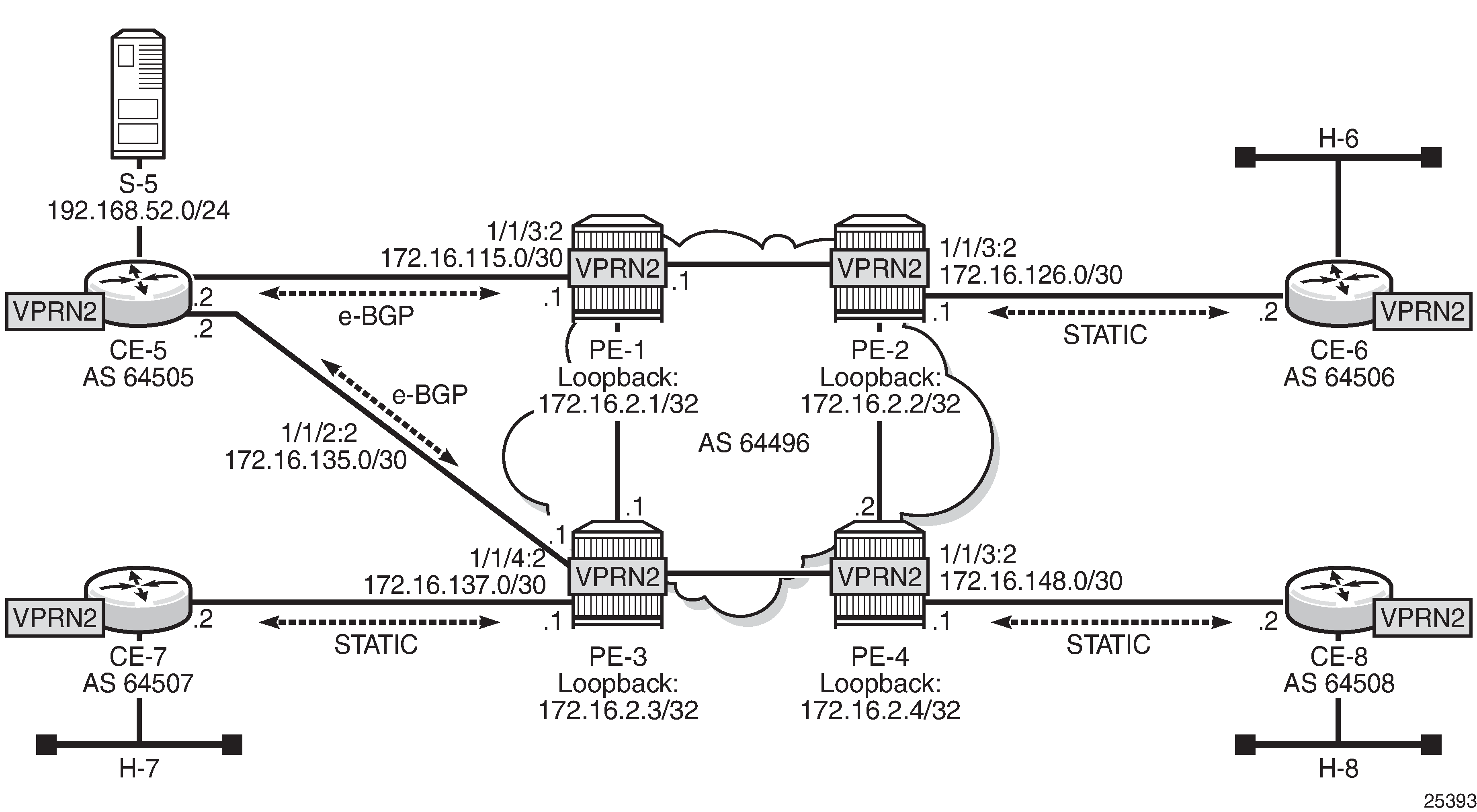
The configuration change with respect to the previous section (P2MP RSVP-TE PMSIs) is an additional interface created in both CE-5 and PE-3 (int-CE-5-PE-3 on CE-5 and int-PE-3-CE-5 on PE-3), the addition of these interfaces to PIM and also the creation an e-BGP session between the two routers. The following is the additional configuration on PE-3 (CE-5 configuration changes are not displayed for brevity).
# on PE-3
configure
    service
        vprn 2
            interface "int-PE-3-CE-5" create
                address 172.16.35.1/30
                sap 1/1/4:2 create
                exit
            exit
            bgp
                group "EXTERNAL"
                    type external
                    peer-as 64505
                    neighbor 172.16.35.2
                    exit
                exit
                no shutdown
            exit
            pim
                interface "int-PE-3-CE-5"
                exit
            exit
        exit
Checking the routes on PE-4, the source is reachable through PE-1 and PE-2 as ECMP is set to 2. If the configuration of the VPRN is provisioned with auto-bind-tunnel resolution-filter rsvp resolution filter, instead of static spoke-SDPs, the command ignore-nh-metric is also needed.
*A:PE-4# configure service vprn 2 ecmp 2
*A:PE-4# show router 2 route-table

===============================================================================
Route Table (Service: 2)
===============================================================================
Dest Prefix[Flags]                            Type    Proto     Age        Pref
      Next Hop[Interface Name]                                    Metric
-------------------------------------------------------------------------------
---snip---
192.168.52.0/24                               Remote  BGP VPN   00h01m42s  170
       192.0.2.1 (tunneled)                                         0
192.168.52.0/24                               Remote  BGP VPN   00h01m42s  170
       192.0.2.3 (tunneled)                                         0
-------------------------------------------------------------------------------
No. of Routes: 11
Flags: n = Number of times nexthop is repeated
       B = BGP backup route available
       L = LFA nexthop available
       S = Sticky ECMP requested
===============================================================================
*A:PE-4#
When PE-4 receives a c-join/prune, PE-4 needs to find the upstream multicast hop (UMH) for the (S,G). This is the upstream multihop selection and is configurable. The values are highest-ip, hash-based, tunnel-status, and unicast-rt-pref
*A:PE-4# configure service vprn 2 mvpn umh-selection
  - no umh-selection
  - umh-selection {highest-ip|hash-based|tunnel-status|unicast-rt-pref}
The default is highest-ip, which is the selection of the highest /32 IP addresses (in this setup, PE-3 is preferred versus PE-1). A BGP c-join is sent with the route target equal to the VRF import extended community distributed by PE-3 for the subnet of the source (see following PE-4 debug).
17 2017/10/07 20:35:31.112 UTC MINOR: DEBUG #2001 vprn2 PIM[vprn 3 vprn2]
"PIM[vprn 3 vprn2]: pimSGUpStateJMribChange
SG (192.168.52.2,232.2.2.2), type <S,G> newMribNhopIp 192.0.2.3
newRpfNbrIp 192.0.2.3 newRpfType REMOTE newRpfIf 73733"

---snip---

20 2017/10/07 20:35:31.112 UTC MINOR: DEBUG #2001 Base Peer 1: 192.0.2.3
"Peer 1: 192.0.2.3: UPDATE
Peer 1: 192.0.2.3 - Send BGP UPDATE:
    Withdrawn Length = 0
    Total Path Attr Length = 76
    Flag: 0x90 Type: 14 Len: 33 Multiprotocol Reachable NLRI:
        Address Family MVPN_IPV4
        NextHop len 4 NextHop 192.0.2.4
        Type: Source-Join Len:22 RD: 64496:203 SrcAS: 64496
                                 Src: 192.168.52.2 Grp: 232.2.2.2
    Flag: 0x40 Type: 1 Len: 1 Origin: 0
    Flag: 0x40 Type: 2 Len: 0 AS Path:
    Flag: 0x80 Type: 4 Len: 4 MED: 0
    Flag: 0x40 Type: 5 Len: 4 Local Preference: 100
    Flag: 0xc0 Type: 8 Len: 4 Community:
        no-export
    Flag: 0xc0 Type: 16 Len: 8 Extended Community:
        target:192.0.2.3:3
"
The second option is hash-based, where the UMH is selected (both PEs are potentially possible UMHs) after hashing the source and group addresses of the stream. For this example, PE-3 is also preferred.
The third option, tunnel-status, is based on the status of the P2MP RSVP tunnel (not available in mLDP or PIM). The roots PE-1 and PE-3 are sending BFD messages to the leaf PE-4 (in fact this is UFD, unidirectional forwarding detection). The c-join from PE-4 for the (S,G) is sent to both PE-1 and PE-3, and in return the traffic is forwarded from both PE-1 and PE-3 for the c-group onto the I-PMSI; therefore PE-4 receives two copies of the c-(S,G) stream. By configuration, the stream from the primary PE-1 is selected by PE-4 to be forwarded to receiver H-8. If BFD messages are no longer received over the primary P2MP LSP, then the stream from the standby PE-3 is selected and forwarded to the receiver.
The configuration on PE-1 and PE-3 is similar and is as follows (only PE-3 is shown):
# on PE-3
configure
    service
        vprn 2
            mvpn
                auto-discovery default
                c-mcast-signaling bgp
                umh-selection tunnel-status
                provider-tunnel
                    inclusive
                        rsvp
                            lsp-template "VRF2"
                            enable-bfd-root 100
                            no shutdown
                        exit
                    exit
                exit
                vrf-target unicast
                exit
            exit
PE-1 and PE-3 are root. On PE-4, BFD is configured as leaf and the primary PE (PE-1) and backup PE (PE-3) are also provisioned:
# on PE-4
configure
    service
        vprn 2
            mvpn
                auto-discovery default
                c-mcast-signaling bgp
                umh-selection tunnel-status
                umh-pe-backup
                    umh-pe 192.0.2.1 standby 192.0.2.3
                exit
                provider-tunnel
                    inclusive
                        rsvp
                            lsp-template "VRF2"
                            enable-bfd-leaf
                            no shutdown
                        exit
                    exit
                exit
                vrf-target unicast
                exit
            exit
This BFD (UFD) configuration on the root establishes a session with the leaf. The root only transmits BFD packets; it doesn’t receive any.
*A:PE-1# show router 2 bfd session

===============================================================================
Legend:
  Session Id = Interface Name | LSP Name | Prefix | RSVP Sess Name | Service Id
  wp = Working path   pp = Protecting path
===============================================================================
BFD Session
===============================================================================
Session Id                                        State      Tx Pkts    Rx Pkts
  Rem Addr/Info/SdpId:VcId                      Multipl     Tx Intvl   Rx Intvl
  Protocols                                        Type     LAG Port     LAG ID
-------------------------------------------------------------------------------
mpls-if-73740                                        Up          330          0
  127.0.0.0                                           3          100          0
  pim                                           central          N/A        N/A
-------------------------------------------------------------------------------
No. of BFD sessions: 1
===============================================================================
*A:PE-1#
On PE-4, two BFD sessions are received, one from each root (note that BFD packets are only received):
*A:PE-4# show router 2 bfd session

===============================================================================
Legend:
  Session Id = Interface Name | LSP Name | Prefix | RSVP Sess Name | Service Id
  wp = Working path   pp = Protecting path
===============================================================================
BFD Session
===============================================================================
Session Id                                        State      Tx Pkts    Rx Pkts
  Rem Addr/Info/SdpId:VcId                      Multipl     Tx Intvl   Rx Intvl
  Protocols                                        Type     LAG Port     LAG ID
-------------------------------------------------------------------------------
mpls-if-73743                                        Up            0        189
  192.0.2.3                                           3         1000        100
  pim                                           central          N/A        N/A
mpls-if-73744                                        Up            0        188
  192.0.2.1                                           3         1000        100
  pim                                           central          N/A        N/A
-------------------------------------------------------------------------------
No. of BFD sessions: 2
===============================================================================
*A:PE-4#
PE-4 delivers the multicast traffic from the primary configured UMH, PE-1. If, as an example of a failure condition, PE-1 goes down (reboot), PE-4 will switch to the PE-3 P2MP LSP.
MDT AFI SAFI for Rosen MVPN
In Rosen MVPN up to version 6, the default MDT is PIM sparse mode only, and there is no auto-discovery mechanism available. In SR OS Release 7.0, and later, it is possible to configure PIM SSM with auto-discovery, using AFI 1 and SAFI 5. Rosen MVPN version 7 allows use of MDT PIM SM or SSM, and auto-discovery based on AFI 1 and SAFI 66 to distribute the default MDT. Rosen MVPN version 9 adds a new MDT NLRI. SR OS has added the capability and support of MDT SAFI as specified in RFC 6037.
MDT SAFI is used to discover PEs in a specific MVPN, so that PIM SSM can be used for default MDT. The basic idea is the same as MVPN BGP auto-discovery, but it uses a different BGP SAFI. BGP messages in which AFI=1 and SAFI=66 are "MDT-SAFI" messages. The NLRI format is 8-byte-RD:IPv4-address followed by the MDT group address. The IPv4 address identifies the PE that originated this route and the RD identifies a VRF in that PE. The group address must be an IPv4 multicast group address and is used to build the P-tunnels.
All PEs attached to a given MVPN must specify the same group-address. MDT-SAFI routes do not carry RTs and the group address is used to associate a received MDT-SAFI route with a VRF.
MDT SAFI can only be used when the implicit provider tunnel is PIM GRE based with a specific IPv4 group address.
For additional information on the use of PIM PMSIs, see NG-MVPN Configuration with PIM.
VPRN 3 Topology used for MDT SAFI shows the topology of VPRN 3.
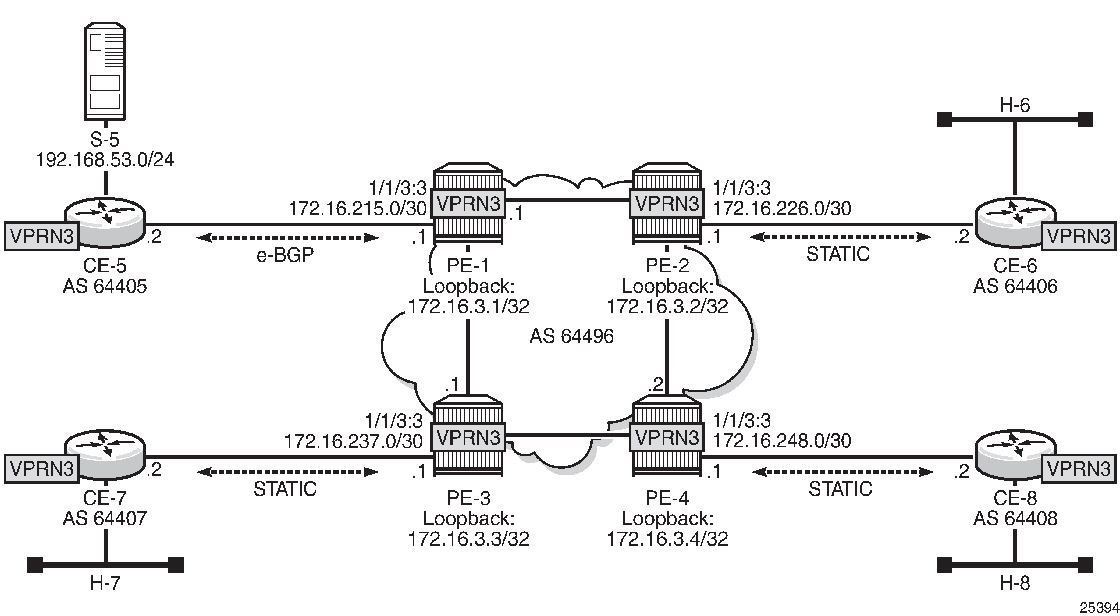
In this scenario, there is no MPLS based PMSI, there is PIM in the core for the control plane and the data traffic is GRE encapsulated. PIM needs to be configured in the base router on interface system and on the other interfaces pointing to other PEs. PIM is used for c-signaling. In addition, auto-discovery is provisioned to use mdt-safi and a PIM SSM inclusive PMSI with address 239.1.1.1 as the default MDT. The configuration is as follows on PE-4:
configure
    router
        pim
            interface "system"
            exit
            interface "int-PE-4-PE-2"
            exit
            interface "int-PE-4-PE-3"
            exit
        exit
    exit
    service
        vprn 3 customer 1 create
            description "PIM SSM / MDT SAFI"
            autonomous-system 64496
            route-distinguisher 64496:304
            vrf-target target:64496:300
            interface "loopback" create
                address 172.16.3.4/32
                loopback
            exit
            interface "int-PE-4-CE-8" create
                address 172.16.248.1/30
                sap 1/1/3:3 create
                exit
            exit
            pim
                interface "loopback"
                exit
                interface "int-PE-4-CE-8"
                exit
            exit
            mvpn
                auto-discovery mdt-safi
                provider-tunnel
                    inclusive
                        pim ssm 239.1.1.1
                        exit
                    exit
                exit
                vrf-target unicast
                exit
            exit
            spoke-sdp 341 create
            exit
            spoke-sdp 342 create
            exit
            spoke-sdp 343 create
            exit
            no shutdown
The following debug output shows a BGP update with MDT AFI SAFI on PE-4:
11 2017/10/07 20:42:28.669 UTC MINOR: DEBUG #2001 Base Peer 1: 192.0.2.1
"Peer 1: 192.0.2.1: UPDATE
Peer 1: 192.0.2.1 - Send BGP UPDATE:
    Withdrawn Length = 0
    Total Path Attr Length = 62
    Flag: 0x90 Type: 14 Len: 26 Multiprotocol Reachable NLRI:
        Address Family MDT-SAFI
        NextHop len 4 NextHop 192.0.2.4
        [MDT-SAFI] Addr 192.0.2.4, Group 239.1.1.1, RD 64496:304
    Flag: 0x40 Type: 1 Len: 1 Origin: 0
    Flag: 0x40 Type: 2 Len: 0 AS Path:
    Flag: 0x80 Type: 4 Len: 4 MED: 0
    Flag: 0x40 Type: 5 Len: 4 Local Preference: 100
    Flag: 0xc0 Type: 16 Len: 8 Extended Community:
        target:64496:300
"
The following output shows the MDT-SAFI routes that have been learned at PE-4:
*A:PE-4# show router bgp routes mdt-safi
===============================================================================
 BGP Router ID:192.0.2.4        AS:64496       Local AS:64496
===============================================================================
 Legend -
 Status codes  : u - used, s - suppressed, h - history, d - decayed, * - valid
                 l - leaked, x - stale, > - best, b - backup, p - purge
 Origin codes  : i - IGP, e - EGP, ? - incomplete

===============================================================================
BGP MDT-SAFI Routes
===============================================================================
Flag  Network                                            LocalPref   MED
      Nexthop                     Group-Addr                         Label
      As-Path
-------------------------------------------------------------------------------
u*>i  64496:301:192.0.2.1                                100         0
      192.0.2.1                   239.1.1.1                          -
      No As-Path
u*>i  64496:302:192.0.2.2                                100         0
      192.0.2.2                   239.1.1.1                          -
      No As-Path
u*>i  64496:303:192.0.2.3                                100         0
      192.0.2.3                   239.1.1.1                          -
      No As-Path
-------------------------------------------------------------------------------
Routes : 3
===============================================================================
*A:PE-4#
Conclusion
This chapter provides information to configure multicast within a VPRN with next generation multicast VPN techniques. Specifically, the use of MPLS I-PMSIs (mLDP and P2MP RSVP-TE), MVPN source redundancy, and the complete set of features needed to interoperate with Rosen MVPN in live deployments are covered.