Weighted ECMP for VPRN over RSVP-TE or SR-TE LSPs
This chapter provides information about Weighted Equal Cost Multipath (ECMP) for Virtual Private Routed Network (VPRN) over Resource Reservation Protocol with Traffic Engineering (RSVP-TE) or Segment Routing with Traffic Engineering (SR-TE) Label Switched Paths (LSPs).
Topics in this chapter include:
Applicability
The information and configuration in this chapter are based on SR OS Release 23.3.R2. Weighted load balancing over Multi Protocol Label Switching (MPLS) LSPs - as described in chapter BGP Weighted ECMP in the Unicast Routing Protocols volume of the 7450 ESS, 7750 SR, and 7950 XRS Advanced Configuration Guide - Part I- is supported in SR OS Release 13.0.R1, and later. Weighted load balancing for VPRN with auto-bind-tunnel over RSVP-TE LSPs is supported in SR OS Release 15.0.R2, and later. Weighted load balancing for VPRN with auto-bind-tunnel over SR-TE LSPs is supported inSR OS Release 15.0.R4, and later.
Overview
Equal Load Balancing
In this chapter, ECMP refers to spraying traffic flows over multiple RSVP-TE or SR-TE LSPs within an ECMP set. ECMP spraying consists of hashing the relevant fields in the packet header and selecting the tunnel next-hop based on the modulo operation of the output of the hash and the number of LSPs present in the ECMP set. The maximum number of LSPs in the ECMP set is defined by the ecmp command.
Only LSPs with the same lowest LSP metric can be part of the ECMP set. If the number of such LSPs exceeds the maximum number of LSPs allowed in the ECMP set as defined by the ecmp command, the LSPs with the lowest tunnel IDs are selected first. By default, all LSPs in the ECMP set have the same weight, and traffic flows are spread evenly over all LSPs in the ECMP set, regardless of the bandwidth of the active path in the LSPs. By default, ECMP is enabled and set to 1.
Regular ECMP in AS 64496 shows that PE-1 sprays the traffic flows equally over two LSPs between PE-1 and PE-3. If three or more LSPs with the same lowest LSP metric were available from PE-1 to PE-3, only two of those would be used, because an ECMP value of 2 allows the traffic to be sprayed over two LSPs.

Unequal Load Balancing
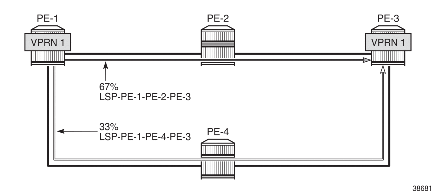
Weighted ECMP sprays traffic flows over MPLS LSPs proportionally to the load-balancing-weight <weight> value configured on each MPLS LSP in the ECMP set. Weighted ECMP in AS 64496 shows that PE-1 forwards two thirds of the traffic flows on LSP-PE-1-PE-2-PE-3 with weight 2 and one third on LSP-PE-1-PE-4-PE-3 with weight 1. Each of the links can be link aggregation group (LAG) ports. For instance, when LSP-PE-1-PE-2-PE-3 uses LAG ports, 67% of the traffic is sprayed evenly over all ports belonging to the LAG.
The LSP load balancing weight can be configured in an LSP template or on an LSP. By default, the load balancing weight equals zero, in which case regular ECMP applies.
The following command is used to configure the weight in an LSP template:
*A:PE-1# configurerouter Base mpls lsp-template "LSPtemplate1" load-balancing-weight ?
  - no load-balancing-weight
  - load-balancing-weight <weight>

 <weight>             : [0..4294967295] Default - 0
The following command is used to configure the weight on an LSP (for example on LSP "LSP-PE-1-PE-2-PE-3"):
*A:PE-1# configurerouter Base mpls lsp "LSP-PE-1-PE-2-PE-3" load-balancing-weight ?
  - load-balancing-weight <weight>
  - no load-balancing-weight

 <weight>             : [0..4294967295] Default - 0
The LSP load balancing weight on LSP-PE-1-PE-2-PE-3 is configured with a value of 2, as follows:
configure
    router Base
        mpls
            path "path-PE-1-PE-2-PE-3"
                hop 10 192.168.12.2 strict
                hop 20 192.168.23.2 strict
                no shutdown
            exit
            lsp "LSP-PE-1-PE-2-PE-3"
                to 192.0.2.3
                path-computation-method local-cspf
                metric 100
                load-balancing-weight 2
                primary "path-PE-1-PE-2-PE-3"
                exit
                no shutdown
            exit
Weighted ECMP is enabled in the vprn 1 bgp-ipvpn mpls auto-bind-tunnel context as follows:
configure
    service
        vprn 1 name "1" customer 1 create
            bgp-ipvpn
                mpls
                    auto-bind-tunnel
                        ecmp 2
                        weighted-ecmp
                    exit
Weighted load balancing within a vprn context can be performed only when the next-hops are associated with the same neighbor and all LSPs in the ECMP set are configured with non-zero load balancing weights. If one or more LSPs in the ECMP set toward a specific next-hop do not have a load balancing weight configured, regular ECMP spraying is used. The weighted ECMP support for ECMP routes applies to both IPv4 and IPv6.
Additionally, it is possible to enable ECMP in the vprn context, with: configure service vprn 1 ecmp <max-ecmp-routes>, to control load balancing to a different next-hop. The weighted-ecmp option in the VPN 1 bgp-ipvpn mpls auto-bind-tunnel context controls load balancing to the same next-hop.
Configuration
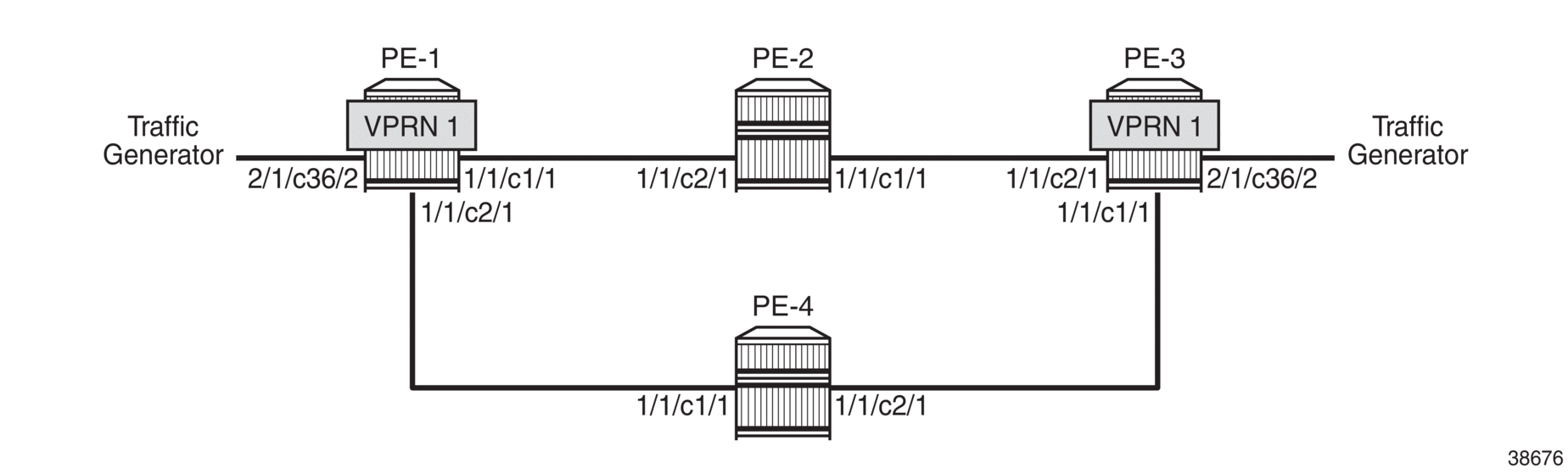
Example Topology shows the example topology with four PEs. VPRN 1 is configured on PE-1 and PE-3. A traffic generator is connected to VPRN 1 SAP 2/1/c36/2 on PE-1 and VPRN 1 SAP 2/1/c36/2 on PE-3. The traffic generator generates multiple traffic flows with random IP addresses and TCP/UDP port numbers. As a result, these flows are sprayed over different MPLS LSPs between PE-1 and PE-3.
The initial configuration on the PEs includes the following:
Cards, MDAs, ports
Router interfaces
IS-IS as IGP (alternatively, OSPF can be used) with traffic engineering enabled
MPLS and RSVP enabled on all router interfaces
The initial configuration on PE-1 is as follows:
configure
    router Base
        interface "int-PE-1-PE-2"
            address 192.168.12.1/30
            port 1/1/c1/1
        exit
        interface "int-PE-1-PE-4"
            address 192.168.14.1/30
            port 1/1/c2/1
        exit
        interface "system"
            address 192.0.2.1/32
        exit
        isis 0
            area-id 49.0001
            traffic-engineering
            interface "system"
            exit
            interface "int-PE-1-PE-2"
                interface-type point-to-point
            exit
            interface "int-PE-1-PE-4"
                interface-type point-to-point
            exit
            no shutdown
        exit
        mpls
            interface "int-PE-1-PE-2"
            exit
            interface "int-PE-1-PE-4"
            exit
            no shutdown
        exit
        rsvp
            no shutdown
        exit
The initial configuration on the other PEs is similar.
With the preceding configuration, MPLS and RSVP are enabled on all interfaces, including the system interface, which is added automatically.
In the next sections, the following use cases are described:
Weighted ECMP for VPRN with Auto-bind-tunnel RSVP-TE
On PE-1, the following paths and LSPs are configured. LSP-PE-1-PE-2-PE-3 is configured with a load balancing weight of 2; LSP-PE-1-PE-4-PE-3 is configured with a load balancing weight of 1.
configure
    router Base
        mpls
            path "path-PE-1-PE-2-PE-3"
                hop 10 192.168.12.2 strict
                hop 20 192.168.23.2 strict
                no shutdown
            exit
            path "path-PE-1-PE-4-PE-3"
                hop 10 192.168.14.2 strict
                hop 20 192.168.34.1 strict
                no shutdown
            exit
            lsp "LSP-PE-1-PE-2-PE-3"
                to 192.0.2.3
                path-computation-method local-cspf
                metric 100
                load-balancing-weight 2
                primary "path-PE-1-PE-2-PE-3"
                exit
                no shutdown
            exit
            lsp "LSP-PE-1-PE-4-PE-3"
                to 192.0.2.3
                path-computation-method local-cspf
                metric 100
                load-balancing-weight 1
                primary "path-PE-1-PE-4-PE-3"
                exit
                no shutdown
            exit
        exit
On PE-1, VPRN 1 is configured as follows. ECMP and weighted ECMP can be configured in the vprn context, for example, configure service vprn 1 ecmp 2 and configure service vprn 1 weighted-ecmp but it is not required when the next-hop for the MPLS LSPs is the same. In this example, ECMP and weighted ECMP are only configured in the vprn 1 bgp-ipvpn mpls auto-bind-tunnel context. The resolution filter only allows RSVP-TE tunnels, no other MPLS LSPs, such as LDP, BGP, or segment routing (SR) tunnels.
configure
    service
        vprn 1 name "1" customer 1 create
            description "CE-1"
            bgp-ipvpn
                mpls
                    auto-bind-tunnel
                        resolution-filter
                            rsvp
                        exit
                        resolution filter
                        ecmp 2
                        weighted-ecmp
                    exit
                    route-distinguisher 64496:1
                    vrf-target target:64496:1
                    no shutdown
                exit
            exit
            interface "loopback1" create
                address 172.16.0.1/32
                ipv6
                    address 2001:db8::1/128
                exit
                loopback
            exit
            interface "int-CE-1-STC" create
                address 192.168.11.1/24
                ipv6
                    address 2001:db8::11:1/120
                exit
                sap 2/1/c36/2 create
                exit
            exit
            no shutdown
        exit
The service configuration on PE-3 is similar.
VPRN 1 is dual stacked. Weighted ECMP applies to both IPv4 and IPv6 traffic streams. BGP is configured for the VPN-IPv4 and VPN-IPv6 address family to exchange the routes used in VPRN 1 between PE-1 and PE-3. The BGP configuration on PE-1 is as follows:
configure
    router Base
        autonomous-system 64496
        bgp
            group "iBGP"
                neighbor 192.0.2.3
                    family vpn-ipv4 vpn-ipv6
                    export "export-vpn-ipv4" "export-vpn-ipv6"
                    peer-as 64496
                exit
The BGP configuration on PE-3 is similar.
The export policies on PE-1 are defined as follows:
configure
    router Base
        policy-options
            begin
            prefix-list "vpn-ipv4"
                prefix 172.16.0.0/16 longer
                prefix 192.168.11.0/24 exact
            exit
            prefix-list "vpn-ipv6"
                prefix 2001:db8::/120 longer
                prefix 2001:db8::11:0/120 exact
            exit
            policy-statement "export-vpn-ipv4"
                entry 10
                    from
                        prefix-list "vpn-ipv4"
                    exit
                    action accept
                    exit
                exit
            exit
            policy-statement "export-vpn-ipv6"
                entry 10
                    from
                        prefix-list "vpn-ipv6"
                    exit
                    action accept
                    exit
                exit
            exit
            commit
The export policies on PE-3 are similar.
With ECMP enabled for MPLS LSPs with the same next-hop and two RSVP-TE LSPs available with equal metric, the route table of VPRN 1 on PE-1 shows two routes for each prefix with the same next-hop 192.0.2.3: one via RSVP LSP 1 and the other via RSVP LSP 2, as follows:
*A:PE-1# show router 1 route-table

===============================================================================
Route Table (Service: 1)
===============================================================================
Dest Prefix[Flags]                            Type    Proto     Age        Pref
      Next Hop[Interface Name]                                    Metric
-------------------------------------------------------------------------------
172.16.0.1/32                                 Local   Local     00h01m16s  0
       loopback1                                                    0
172.16.0.3/32 [2]                             Remote  BGP VPN   00h00m29s  170
       192.0.2.3 (tunneled:RSVP:1)                                  100
172.16.0.3/32 [2]                             Remote  BGP VPN   00h00m29s  170
       192.0.2.3 (tunneled:RSVP:2)                                  100
192.168.11.0/24                               Local   Local     00h01m16s  0
       int-CE-1-STC                                                 0
192.168.33.0/24 [2]                           Remote  BGP VPN   00h00m29s  170
       192.0.2.3 (tunneled:RSVP:1)                                  100
192.168.33.0/24 [2]                           Remote  BGP VPN   00h00m29s  170
       192.0.2.3 (tunneled:RSVP:2)                                  100
-------------------------------------------------------------------------------
No. of Routes: 6
Flags: n = Number of times nexthop is repeated
       B = BGP backup route available
       L = LFA nexthop available
       S = Sticky ECMP requested
===============================================================================
The flag [2] indicates that next-hop 192.0.2.3 occurs twice for the prefix 172.16.0.3/32; next-hop 192.0.2.3 also occurs twice for the prefix 192.168.33.0/24.
The following IPv6 route table is similar, with next-hop 192.0.2.3 occurring twice for prefix 2001:db8::3/128 and twice for prefix 2001:db8::33:0/120.
*A:PE-1# show router 1 route-table ipv6

===============================================================================
IPv6 Route Table (Service: 1)
===============================================================================
Dest Prefix[Flags]                            Type    Proto     Age        Pref
      Next Hop[Interface Name]                                    Metric
-------------------------------------------------------------------------------
2001:db8::1/128                               Local   Local     00h01m15s  0
       loopback1                                                    0
2001:db8::3/128 [2]                           Remote  BGP VPN   00h00m29s  170
       192.0.2.3 (tunneled:RSVP:1)                                  100
2001:db8::3/128 [2]                           Remote  BGP VPN   00h00m29s  170
       192.0.2.3 (tunneled:RSVP:2)                                  100
2001:db8::11:0/120                            Local   Local     00h01m15s  0
       int-CE-1-STC                                                 0
2001:db8::33:0/120 [2]                        Remote  BGP VPN   00h00m29s  170
       192.0.2.3 (tunneled:RSVP:1)                                  100
2001:db8::33:0/120 [2]                        Remote  BGP VPN   00h00m29s  170
       192.0.2.3 (tunneled:RSVP:2)                                  100
-------------------------------------------------------------------------------
No. of Routes: 6
Flags: n = Number of times nexthop is repeated
       B = BGP backup route available
       L = LFA nexthop available
       S = Sticky ECMP requested
===============================================================================
The following tunnel table output on PE-1 shows that RSVP-TE LSP 1 goes via PE-2 (next-hop 192.168.12.2) and RSVP-TE LSP 2 via PE-4 (next-hop 192.168.14.2):
*A:PE-1# show router tunnel-table

===============================================================================
IPv4 Tunnel Table (Router: Base)
===============================================================================
Destination           Owner     Encap TunnelId  Pref   Nexthop        Metric
   Color
-------------------------------------------------------------------------------
192.0.2.3/32          rsvp      MPLS  1         7      192.168.12.2   100
192.0.2.3/32          rsvp      MPLS  2         7      192.168.14.2   100
-------------------------------------------------------------------------------
Flags: B = BGP or MPLS backup hop available
       L = Loop-Free Alternate (LFA) hop available
       E = Inactive best-external BGP route
       k = RIB-API or Forwarding Policy backup hop
===============================================================================
To verify the weighted load balancing between the two RSVP-TE LSPs, the traffic generator sends multiple IPv4 and IPv6 traffic flows with random IP addresses and TCP/UDP port numbers via PE-1 to PE-3. The traffic enters PE-1 through port 2/1/c36/2. When LSP-PE-1-PE-2-PE-3 is configured with weight 2 and LSP-PE-1-PE-4-PE-3 with weight 1, PE-1 forwards two thirds of the traffic via port 1/1/c1/1 toward PE-2 and one third of the traffic via port 1/1/c2/1 toward PE-3, as follows:
*A:PE-1# monitor port 1/1/c1/1 1/1/c2/1 2/1/c36/2 rate interval 3 repeat 3

===============================================================================
Monitor statistics for Ports
===============================================================================
                                                   Input                 Output
-------------------------------------------------------------------------------
---snip---
-------------------------------------------------------------------------------
At time t = 6 sec (Mode: Rate)
-------------------------------------------------------------------------------
Port 1/1/c1/1
-------------------------------------------------------------------------------
Octets                                               139                 431549
Packets                                                2                    419
Errors                                                 0                      0
Bits                                                1112                3452392
Utilization (% of port capacity)                   ~0.00                   0.03

Port 1/1/c2/1
-------------------------------------------------------------------------------
Octets                                                46                 180781
Packets                                                0                    177
---snip---

Port 2/1/c36/2
-------------------------------------------------------------------------------
Octets                                            608256                      0
Packets                                              594                      0
---snip---
===============================================================================
This can also be verified as follows:
*A:PE-1# show port 1/1/c1/1 statistics

===============================================================================
Port Statistics on Slot 1
===============================================================================
Port                        Ingress Packets                  Ingress Octets
Id                           Egress Packets                   Egress Octets
-------------------------------------------------------------------------------
1/1/c1/1                                 42                            4121
                                      10900                        11209443
===============================================================================

*A:PE-1# show port 1/1/c2/1 statistics

===============================================================================
Port Statistics on Slot 1
===============================================================================
Port                        Ingress Packets                  Ingress Octets
Id                           Egress Packets                   Egress Octets
-------------------------------------------------------------------------------
1/1/c2/1                                 36                            3557
                                       4549                         4661813
===============================================================================

*A:PE-1# show port 2/1/c36/2 statistics

===============================================================================
Port Statistics on Slot 2
===============================================================================
Port                        Ingress Packets                  Ingress Octets
Id                           Egress Packets                   Egress Octets
-------------------------------------------------------------------------------
2/1/c36/2                             15372                        15740928
                                          0                               0
===============================================================================
Restrictions
All RSVP-TE LSPs in the ECMP set must have a load balancing weight configured. When at least one RSVP-TE LSP in the ECMP set is configured without weight, regular ECMP is applied.
RSVP-TE LSP without Weight in ECMP Set
If one of the RSVP-TE LSPs in the ECMP set does not have a load balancing weight configured, the traffic flows are sprayed equally between all RSVP-TE LSPs, regardless of the configured weight of the other RSVP-TE LSPs in the ECMP set.
On PE-1, LSP-PE-1-PE-2-PE-3 is configured without a load balancing weight, as follows:
configure
    router Base
        mpls
            lsp "LSP-PE-1-PE-2-PE-3"
                no load-balancing-weight
LSP-PE-1-PE-4-PE-3 is still configured with a load balancing weight of 1, but it is impossible to calculate its relative weight, because the sum of the weight values is not defined. Therefore, PE-1 reverts to regular ECMP for the load balancing between the two RSVP-TE LSPs to PE-3. When the traffic generator sends multiple traffic flows via PE-1 to PE-3, the load is spread equally over both RSVP-TE LSPs, as shown in the following monitor output. Port 1/1/c1/1 is used for traffic sent via LSP-PE-1-PE-2-PE-3 and port 1/1/c2/1 for traffic sent via LSP-PE-1-PE-4-PE-3.
*A:PE-1# monitor port 1/1/c1/1 1/1/c2/1 2/1/c36/2 rate interval 3 repeat 3

===============================================================================
Monitor statistics for Ports
===============================================================================
                                                   Input                 Output
-------------------------------------------------------------------------------
---snip---
-------------------------------------------------------------------------------
At time t = 6 sec (Mode: Rate)
-------------------------------------------------------------------------------
Port 1/1/c1/1
-------------------------------------------------------------------------------
Octets                                                21                 304157
Packets                                                0                    295
Errors                                                 0                      0
Bits                                                 168                2433256
Utilization (% of port capacity)                   ~0.00                   0.02

Port 1/1/c2/1
-------------------------------------------------------------------------------
Octets                                                21                 305837
Packets                                                0                    297
---snip---

Port 2/1/c36/2
-------------------------------------------------------------------------------
Octets                                            605867                      0
Packets                                              592                      0
---snip---
===============================================================================
The configuration is restored as follows:
configure
    router Base
        mpls
            lsp "LSP-PE-1-PE-2-PE-3"
                load-balancing-weight 2
Weighted ECMP for an SDP used as a spoke SDP in a VPRN
The following LSPs are configured on PE-1. The LSP load balancing weight values are 4 and 1 and the metric is 101 for both LSPs.
configure
    router Base
        mpls
            lsp "LSP-PE-1-PE-2-PE-3-spoke"
                to 192.0.2.3
                path-computation-method local-cspf
                metric 101
                load-balancing-weight 4
                primary "path-PE-1-PE-2-PE-3"
                exit
                no shutdown
            exit
            lsp "LSP-PE-1-PE-4-PE-3-spoke"
                to 192.0.2.3
                path-computation-method local-cspf
                metric 101
                load-balancing-weight 1
                primary "path-PE-1-PE-4-PE-3"
                exit
                no shutdown
            exit
            no shutdown
        exit
        rsvp
            no shutdown
        exit
Similar LSPs are configured on PE-3.
On PE-1, an SDP is configured, as follows:
configure
    service
        sdp 13 mpls create
            far-end 192.0.2.3
            lsp "LSP-PE-1-PE-2-PE-3-spoke"
            lsp "LSP-PE-1-PE-4-PE-3-spoke"
            no shutdown
        exit
A similar SDP is configured on PE-3.
These SDPs are configured as spoke SDPs in a VPRN, as follows:
configure
    service
        vprn 1
            spoke-sdp 13 create
        exit

configure
    router Base
        ldp
            no shutdown
        exit
On PE-1, weighted ECMP is enabled on an SDP, as follows:
configure
    service
        sdp 13
            weighted-ecmp
        exit
The ECMP configuration on PE-3 is similar.
*A:PE-1# show router 1 route-table

===============================================================================
Route Table (Service: 1)
===============================================================================
Dest Prefix[Flags]                            Type    Proto     Age        Pref
      Next Hop[Interface Name]                                    Metric
-------------------------------------------------------------------------------
172.16.0.1/32                                 Local   Local     00h21m51s  0
       loopback1                                                    0
172.16.0.3/32                                 Remote  BGP VPN   00h01m31s  170
       192.0.2.3 (tunneled)                                         0
192.168.11.0/24                               Local   Local     00h21m51s  0
       int-CE-1-STC                                                 0
192.168.33.0/24                               Remote  BGP VPN   00h01m31s  170
       192.0.2.3 (tunneled)                                         0
-------------------------------------------------------------------------------
No. of Routes: 4
Flags: n = Number of times nexthop is repeated
       B = BGP backup route available
       L = LFA nexthop available
       S = Sticky ECMP requested
===============================================================================
*A:PE-1# show router tunnel-table

===============================================================================
IPv4 Tunnel Table (Router: Base)
===============================================================================
Destination           Owner     Encap TunnelId  Pref   Nexthop        Metric
   Color
-------------------------------------------------------------------------------
192.0.2.3/32          sdp       MPLS  13        5      192.0.2.3      0
---snip---
192.0.2.3/32          rsvp      MPLS  3         7      192.168.12.2   101
192.0.2.3/32          rsvp      MPLS  4         7      192.168.14.2   101
-------------------------------------------------------------------------------
Flags: B = BGP or MPLS backup hop available
       L = Loop-Free Alternate (LFA) hop available
       E = Inactive best-external BGP route
       k = RIB-API or Forwarding Policy backup hop
===============================================================================
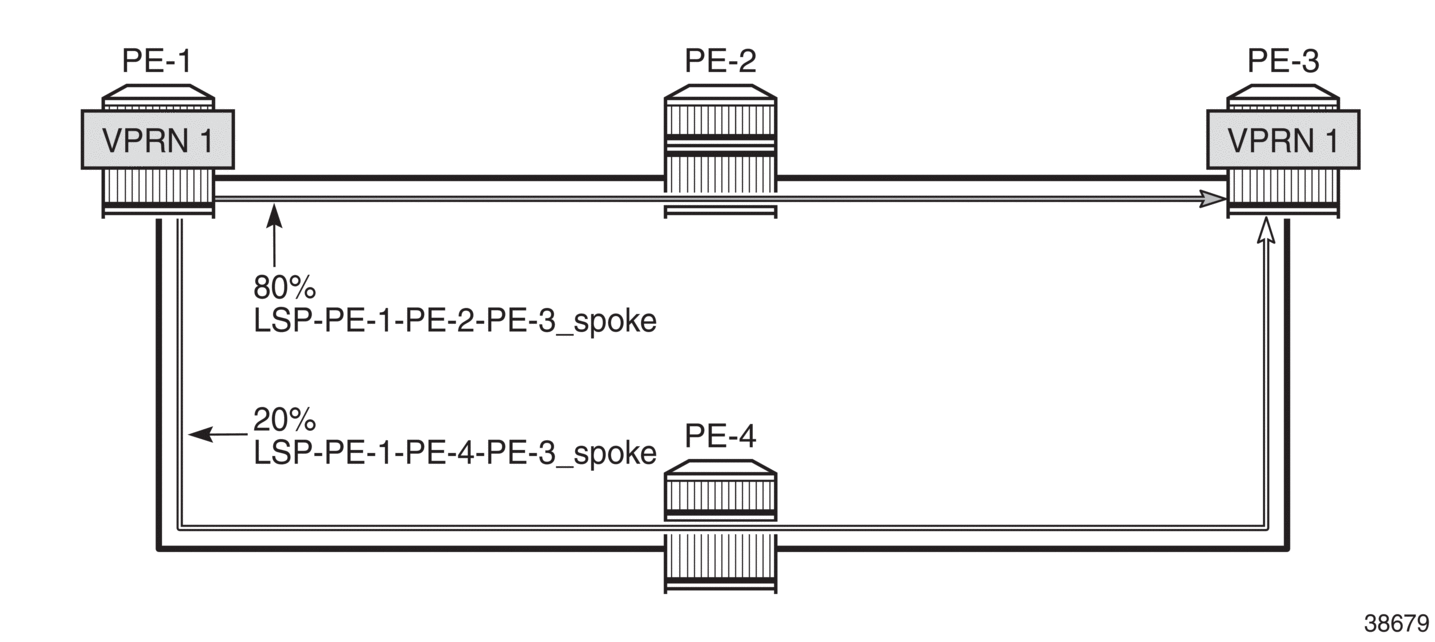
To verify the weighted load balancing between the two RSVP-TE LSPs, the traffic generator sends multiple IPv4 traffic flows with random IP addresses and TCP/UDP port numbers via PE-1 to PE-3. The traffic enters PE-1 through port 2/1/c36/2. When LSP-PE-1-PE-2-PE-3-spoke is configured with weight 4 and LSP-PE-1-PE-4-PE-3-spoke with weight 1, PE-1 forwards four fifths of the traffic via port 1/1/c1/1 toward PE-2 and one fifth of the traffic via port 1/1/c2/1 toward PE-3, as follows:
*A:PE-1# monitor port 1/1/c1/1 1/1/c2/1 2/1/c36/2 rate interval 3 repeat 3

===============================================================================
Monitor statistics for Ports
===============================================================================
                                                   Input                 Output
-------------------------------------------------------------------------------
---snip---
-------------------------------------------------------------------------------
At time t = 6 sec (Mode: Rate)
-------------------------------------------------------------------------------
Port 1/1/c1/1
-------------------------------------------------------------------------------
Octets                                                74                 489052
Packets                                                1                    476
Errors                                                 0                      0
Bits                                                 592                3912416
Utilization (% of port capacity)                   ~0.00                   0.03

Port 1/1/c2/1
-------------------------------------------------------------------------------
Octets                                                61                 118053
Packets                                                0                    115
---snip---

Port 2/1/c36/2
-------------------------------------------------------------------------------
Octets                                            602112                      0
Packets                                              588                      0
---snip---
===============================================================================
Weighted ECMP over RSVP LSPs used in a spoke SDP shows how the traffic flows are sprayed over the two RSVP LSPs:
Weighted ECMP for VPRN with Auto-bind-tunnel SR-TE
The following configuration is added to enable SR-ISIS on PE-1.
configure
    router Base
        mpls-labels
            sr-labels start 20000 end 20099
        exit
        isis 0
            advertise-router-capability as
            interface "system"
                ipv4-node-sid label 20001
            exit
            segment-routing
                prefix-sid-range start-label 20000 max-index 99
                no shutdown
            exit
        exit
The configuration on the other PEs is identical, except for the ipv4-node-sid label value.
The following SR-TE LSPs are configured on PE-1. For more information about SR-TE LSPs, see the Segment Routing Traffic Engineered Tunnels chapter. The load balancing weight values are 75 and 25. The values 3 and 1, which have the same ratio, can be used instead.
configure
    router Base
        mpls
            lsp "LSP-PE-1-PE-2-PE-3_SR-TE" sr-te
                to 192.0.2.3
                load-balancing-weight 75
                primary "path-PE-1-PE-2-PE-3"
                exit
                no shutdown
            exit
            lsp "LSP-PE-1-PE-4-PE-3_SR-TE" sr-te
                to 192.0.2.3
                load-balancing-weight 25
                primary "path-PE-1-PE-4-PE-3"
                exit
                no shutdown
            exit
The configuration on PE-3 is similar.
The following tunnel table on PE-1 shows two SR-TE tunnels with equal metrics: SR-TE tunnel 655362 has PE-2 as next-hop (192.168.12.2) and SR-TE tunnel 655363 has PE-4 as next-hop (192.168.14.2).
*A:PE-1# show router tunnel-table protocol sr-te

===============================================================================
IPv4 Tunnel Table (Router: Base)
===============================================================================
Destination           Owner     Encap TunnelId  Pref   Nexthop        Metric
   Color
-------------------------------------------------------------------------------
192.0.2.3/32          sr-te     MPLS  655362    8      192.168.12.2   16777215
192.0.2.3/32          sr-te     MPLS  655363    8      192.168.14.2   16777215
-------------------------------------------------------------------------------
Flags: B = BGP or MPLS backup hop available
       L = Loop-Free Alternate (LFA) hop available
       E = Inactive best-external BGP route
       k = RIB-API or Forwarding Policy backup hop
===============================================================================
The resolution filter for VPRN 1 is configured on PE-1 and PE-3 to only allow SR-TE tunnels. ECMP and weighted ECMP are enabled in the vprn 1 bgp-ipvpn mpls auto-bind-tunnel context.
configure
    service
        vprn 1 name "1" customer 1 create
            description "CE-1"
            bgp-ipvpn
                mpls
                    auto-bind-tunnel
                        resolution-filter
                            sr-te
                        exit
                        resolution filter
                        ecmp 2
                        weighted-ecmp
                    exit
                    route-distinguisher 64496:1
                    vrf-target target:64496:1
                    no shutdown
                exit
            exit
            interface "loopback1" create
                address 172.16.0.1/32
                ipv6
                    address 2001:db8::1/128
                exit
                loopback
            exit
            interface "int-CE-1-STC" create
                address 192.168.11.1/24
                ipv6
                    address 2001:db8::11:1/120
                exit
                sap 2/1/c36/2 create
                exit
            exit
            no shutdown
        exit
The following route table for VPRN 1 on PE-1 shows two entries for each remote prefix with the same next-hop 192.0.2.3 and a different SR-TE LSP: SR-TE tunnel 655362 and SR-TE tunnel 655363.
*A:PE-1# show router 1 route-table

===============================================================================
Route Table (Service: 1)
===============================================================================
Dest Prefix[Flags]                            Type    Proto     Age        Pref
      Next Hop[Interface Name]                                    Metric
-------------------------------------------------------------------------------
172.16.0.1/32                                 Local   Local     00h39m10s  0
       loopback1                                                    0
172.16.0.3/32 [2]                             Remote  BGP VPN   00h01m15s  170
       192.0.2.3 (tunneled:SR-TE:655362)                            16777215
172.16.0.3/32 [2]                             Remote  BGP VPN   00h01m15s  170
       192.0.2.3 (tunneled:SR-TE:655363)                            16777215
192.168.11.0/24                               Local   Local     00h39m10s  0
       int-CE-1-STC                                                 0
192.168.33.0/24 [2]                           Remote  BGP VPN   00h01m15s  170
       192.0.2.3 (tunneled:SR-TE:655362)                            16777215
192.168.33.0/24 [2]                           Remote  BGP VPN   00h01m15s  170
       192.0.2.3 (tunneled:SR-TE:655363)                            16777215
-------------------------------------------------------------------------------
No. of Routes: 6
Flags: n = Number of times nexthop is repeated
       B = BGP backup route available
       L = LFA nexthop available
       S = Sticky ECMP requested
===============================================================================
The following IPv6 route table for VPRN 1 is similar:
*A:PE-1# show router 1 route-table ipv6

===============================================================================
IPv6 Route Table (Service: 1)
===============================================================================
Dest Prefix[Flags]                            Type    Proto     Age        Pref
      Next Hop[Interface Name]                                    Metric
-------------------------------------------------------------------------------
2001:db8::1/128                               Local   Local     00h39m09s  0
       loopback1                                                    0
2001:db8::3/128 [2]                           Remote  BGP VPN   00h01m15s  170
       192.0.2.3 (tunneled:SR-TE:655362)                            16777215
2001:db8::3/128 [2]                           Remote  BGP VPN   00h01m15s  170
       192.0.2.3 (tunneled:SR-TE:655363)                            16777215
2001:db8::11:0/120                            Local   Local     00h39m09s  0
       int-CE-1-STC                                                 0
2001:db8::33:0/120 [2]                        Remote  BGP VPN   00h01m15s  170
       192.0.2.3 (tunneled:SR-TE:655362)                            16777215
2001:db8::33:0/120 [2]                        Remote  BGP VPN   00h01m15s  170
       192.0.2.3 (tunneled:SR-TE:655363)                            16777215
-------------------------------------------------------------------------------
No. of Routes: 6
Flags: n = Number of times nexthop is repeated
       B = BGP backup route available
       L = LFA nexthop available
       S = Sticky ECMP requested
===============================================================================
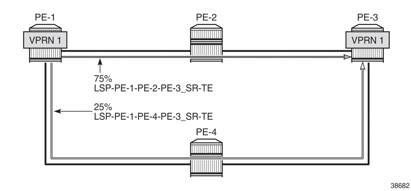
When multiple IPv4 and IPv6 traffic flows are sent from PE-1 to PE-3, the load balancing is weighted: 75% is sent via port 1/1/c1/1 toward PE-2 (LSP-PE-1-PE-2-PE-3_SR-TE) and 25% is sent via port 1/1/c2/1 toward PE-4 (LSP-PE-1-PE-4-PE-3_SR-TE), as follows:
*A:PE-1# monitor port 1/1/c1/1 1/1/c2/1 2/1/c36/2 rate interval 3 repeat 3

===============================================================================
Monitor statistics for Ports
===============================================================================
                                                   Input                 Output
-------------------------------------------------------------------------------
---snip---
-------------------------------------------------------------------------------
At time t = 6 sec (Mode: Rate)
-------------------------------------------------------------------------------
Port 1/1/c1/1
-------------------------------------------------------------------------------
Octets                                                98                 453453
Packets                                                1                    440
Errors                                                 0                      0
Bits                                                 784                3627624
Utilization (% of port capacity)                   ~0.00                   0.03

Port 1/1/c2/1
-------------------------------------------------------------------------------
Octets                                                43                 154231
Packets                                                1                    150
---snip---

Port 2/1/c36/2
-------------------------------------------------------------------------------
Octets                                            595968                      0
Packets                                              582                      0
---snip---
Weighted ECMP over SR-TE LSPs in AS 64496 shows how the traffic flows are sprayed over the two SR-TE LSPs:
Conclusion
Operators can control how traffic in a VPRN is load balanced unequally over multiple transport tunnels by defining a load balancing weight factor on each LSP and enabling weighted ECMP in the VPRN. In this chapter, weighted ECMP for VPRN over transport LSPs is enabled for RSVP-TE tunnels and for SR-TE tunnels.