NG-MVPN Inter-AS Model C Using Non-Segmented mLDP Tunnels
This chapter provides information about NG-MVPN Inter-AS Model C Using Non-Segmented mLDP Tunnels.
Topics in this chapter include:
Applicability
The information and configuration in this chapter are based on SR OS Release 15.0.R9.
No specific configuration is required to support non-segmented multicast Label Distribution Protocol (mLDP) for inter-AS model C. However, recursive-opaque mLDP Forwarding Equivalence Class (FEC) functionality must be supported.
The configuration of multicast in a VPRN is described in the NG-MVPN Configuration with MPLS chapter.
Overview
Multicast in an inter-AS model C network can be implemented using Rosen, where the set of Multicast Distribution Trees (MDTs) are signaled using Protocol Independent Multicast Source-Specific Mode (PIM-SSM).
It is also possible to create MDTs between PEs in different Autonomous Systems (ASs) for Next-Generation MVPN (NG-MVPN) using non-segmented dynamic multicast LDP (mLDP) trees, where the root and leaf PEs are in different ASs. This chapter describes the configuration of MVPN services between PEs in different ASs using NG-MVPN techniques.
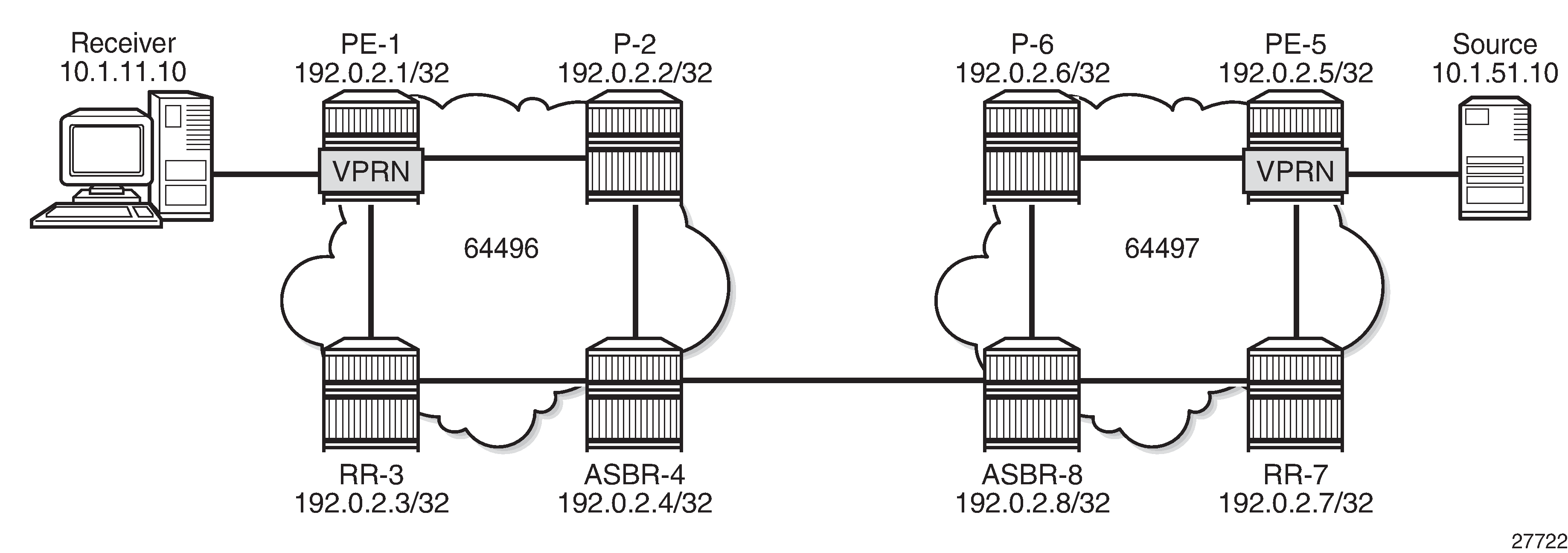
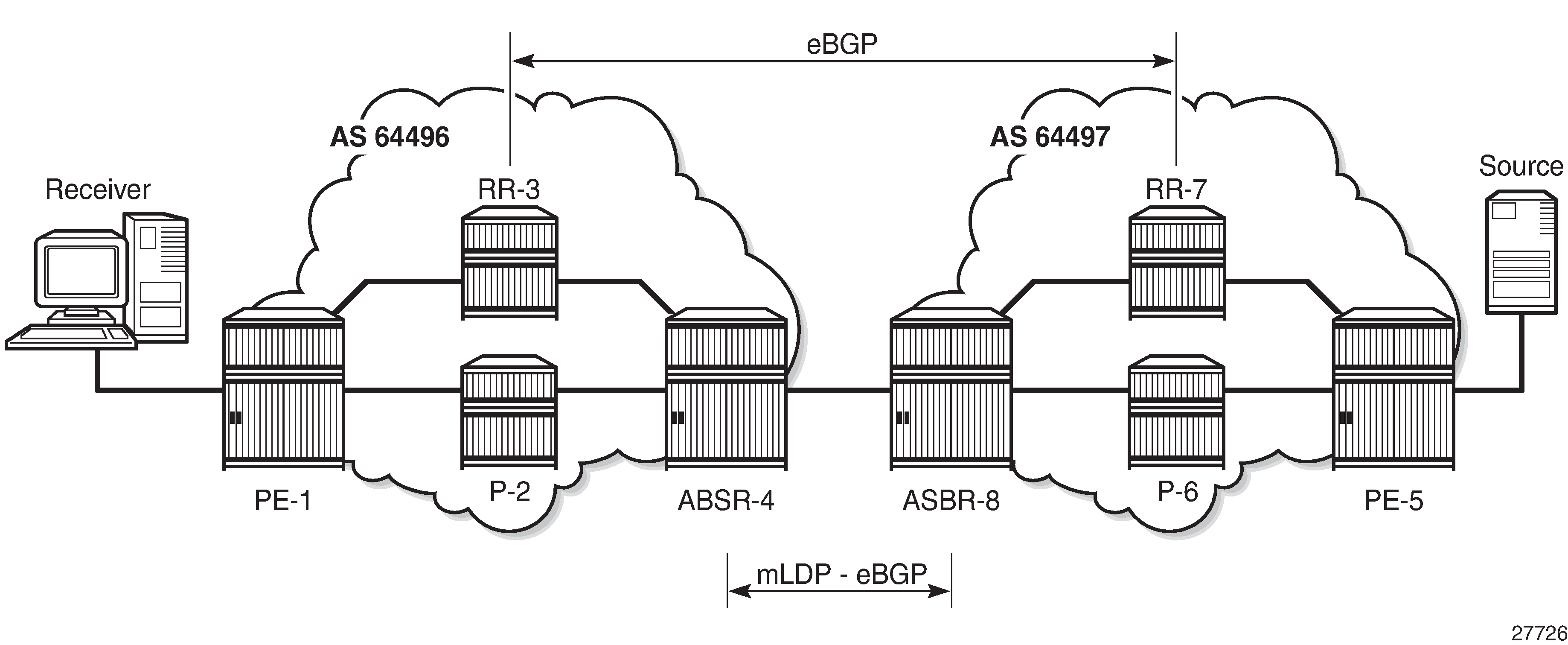
NG-MVPN Inter-AS Model C shows an example of a network comprising routers in two neighboring ASs, modeled as an inter-AS model C network; see the Inter-AS VPRN Model C chapter.
A VPRN instance exists in PE-1 and PE-5, with a single source and receiver connected as per Figure 1. RR-3 is an off the data path Route Reflector (RR) for the VPN-IPv4 address family, and ASBR-4 is RR for the label IPv4 address family in AS 64496. PE-1 is client to both RRs. The situation in AS 64497 is similar.
The multicast source located at address 10.1.51.10 in AS 64497 generates multicast traffic with group address 239.255.0.1, and the receiver at address 10.1.11.10 in AS 64496 will become a member of the multicast group using IGMPv3 signaling. No multicast protocols are configured on the ASBRs.
In an MVPN, a transport tunnel is signaled that will carry multicast traffic from source PE to any receiver PE that has multicast routers attached, or hosts that want to become multicast group members. In this case, an mLDP tunnel is signaled between source PE and destination PEs to carry multicast traffic across the multi-AS provider network.
An mLDP Provider Multicast Service Interface (PMSI), also known as the provider tunnel, is established between PEs that declare membership to the MVPN, by generating and advertising an MVPN type 1 intra-AD (Auto-Discovery) BGP route. This route contains a PMSI Tunnel Attribute (PTA) that provides the tunnel type, the root node, and the LSP ID. Upon receipt of the intra-AD route, the receiving PE checks the route validity so that it can be imported into the VPRN instance. If the route is valid, the receiving router signals a point-to-multipoint (P2MP) LDP label mapping message toward the root address contained within the PTA of the intra-AD route. At the root, MPLS-encapsulated multicast traffic is forwarded to the downstream router by pushing on a label received from the downstream router.
Inter-AS model C unicast requires the RRs in peer ASs to establish a multi-hop EBGP session over which VPN-IPv4 routes can then be exchanged. If RRs are not used, PEs in the peer ASs can exchange the VPN-IPv4 and MVPN-IPv4 routes over a multi-hop eBGP session. Therefore, model C also requires the PE system addresses to be advertised across the AS boundary first.
The path for inter-AS unicast traffic is resolved using VPN-IPv4 routes learnt via the multi-hop eBGP session between RR-3 and RR-7 and label-ipv4 routes learnt via ASBR-4 and ASBR-8. In a unicast environment, traffic from PE-1 to PE-5 takes the following path:
The tunnel from PE-1 to ASBR-4 comprises of three MPLS labels: the MPLS transport label to reach ASBR-4, followed by the MPLS label to reach PE-5 (bgp label-ipv4 learnt from ASBR-4), followed by the label associated with the VPN-IPv4 route.
ASBR-4 pops the outer-most MPLS transport label and forwards to ASBR-8.
ASBR-8 swaps the outer MPLS label (bgp label-ipv4) with the MPLS transport label to reach PE-5.
PE-5 pops the outer MPLS label and uses the VPRN label to forward traffic to the appropriate VPRN.
Unlike unicast, multicast requires a non-segmented provider tunnel for traffic to be routed from the root PE toward the receiver routers. This means that the tunnel must traverse multiple ASs without decapsulating and encapsulating labels at the AS boundaries, and therefore, must be non-segmented.
If the provider tunnel uses mLDP, the receivers will initiate the signaling by sending an LDP label mapping message along the control path toward the root. This follows the path of the intra-AD route that advertises the root of the ingress PMSI (I-PMSI). An mLDP label mapping message consists of an allocated label L, with FEC element <X,Y>, where X identifies the root node and Y is the opaque value, so the P2MP label mapping can be denoted as <X,Y,L>.
The FEC element contains the root address of the LSP plus a variable-length opaque value. The opaque value contains information meaningful to the root and leaf routers, but not to intermediate routers; for example, a P2MP LSP ID or a nested opaque value.
The root address is the system address of PE-5 (the router that advertised the intra-AD route) which is reachable via ASBR-4.
However, in an mLDP environment, each router must take part in the signaling of the P2MP LSP, but not every router has an MVPN route, so any mLDP label mapping message received by P-2 to the root address of PE-5 will be dropped. A solution to this is described in RFC 6512, Using Multipoint LDP When the Backbone Has No Route to the Root, as follows.
PE-1 signals an mLDP LSP as if the root is at ASBR-4. P-2 has a route to ASBR-4 because it participates in the IGP through the same IGP instance. The actual root address located in PE-5 is encapsulated in the mLDP label mapping message originated by PE-1 as an inner root address. This is a recursive FEC type 7; the root (PE-5) is encapsulated within a FEC element as an opaque value.
ASBR-4 receives the intra-AD MVPN route advertised by PE-5 with BGP next-hop ASBR-8.
mLDP Message Opaque Value Types in MVPN inter-AS Model C shows the opaque value types used in MVPN inter-AS model C.
Opaque Type |
Opaque Name |
Use |
FEC Element Representation |
|---|---|---|---|
1 |
Generic |
VPRN local AS |
Root, Opaque<P2MP ID> |
7 |
Recursive FEC |
Inter-AS model C mLDP |
<ASBR, Opaque < Root, P2MP ID>> |
Configuration
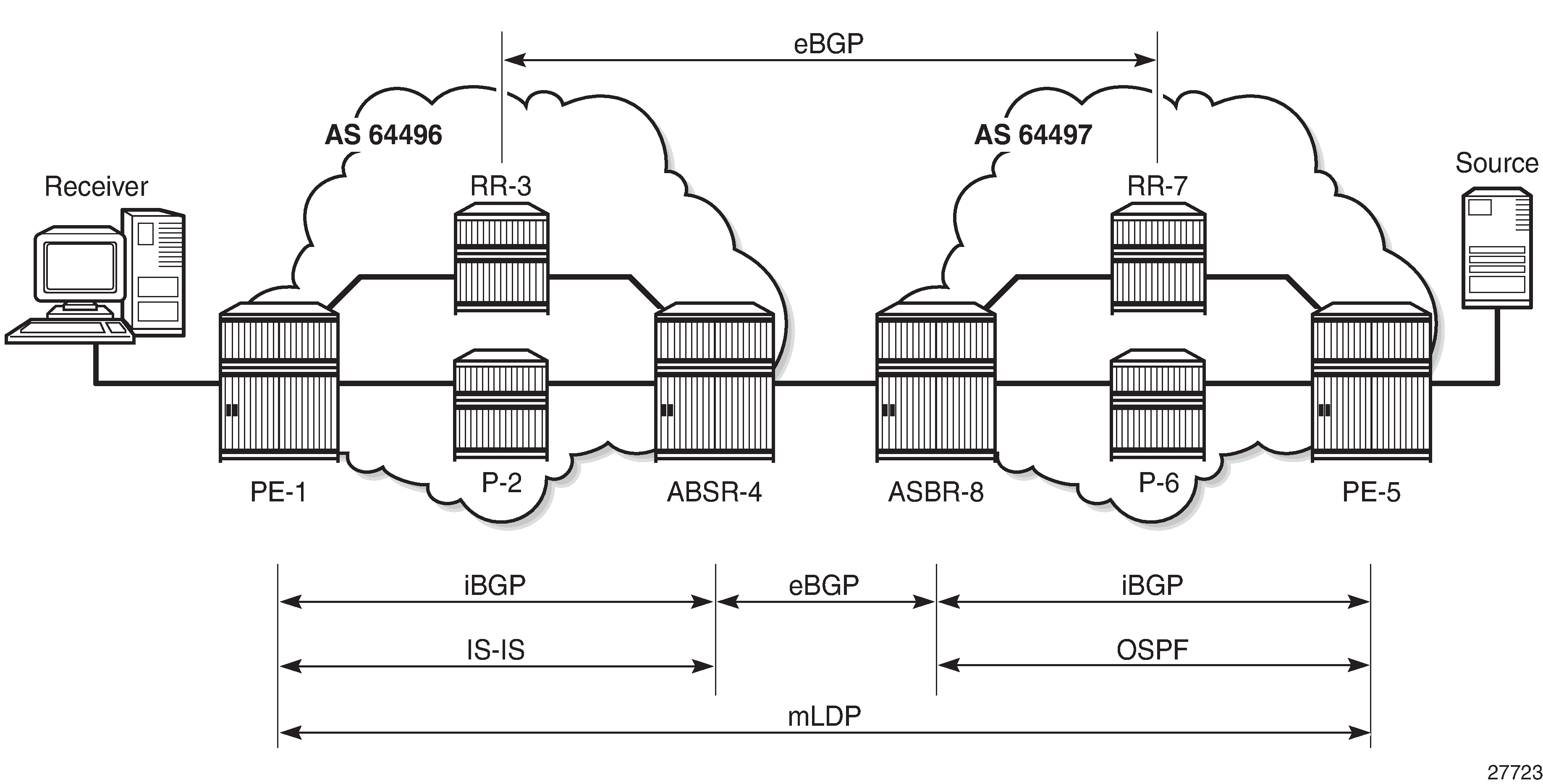
Inter-AS MVPN Protocol Requirements shows the required protocol configuration and peering.
AS 64496
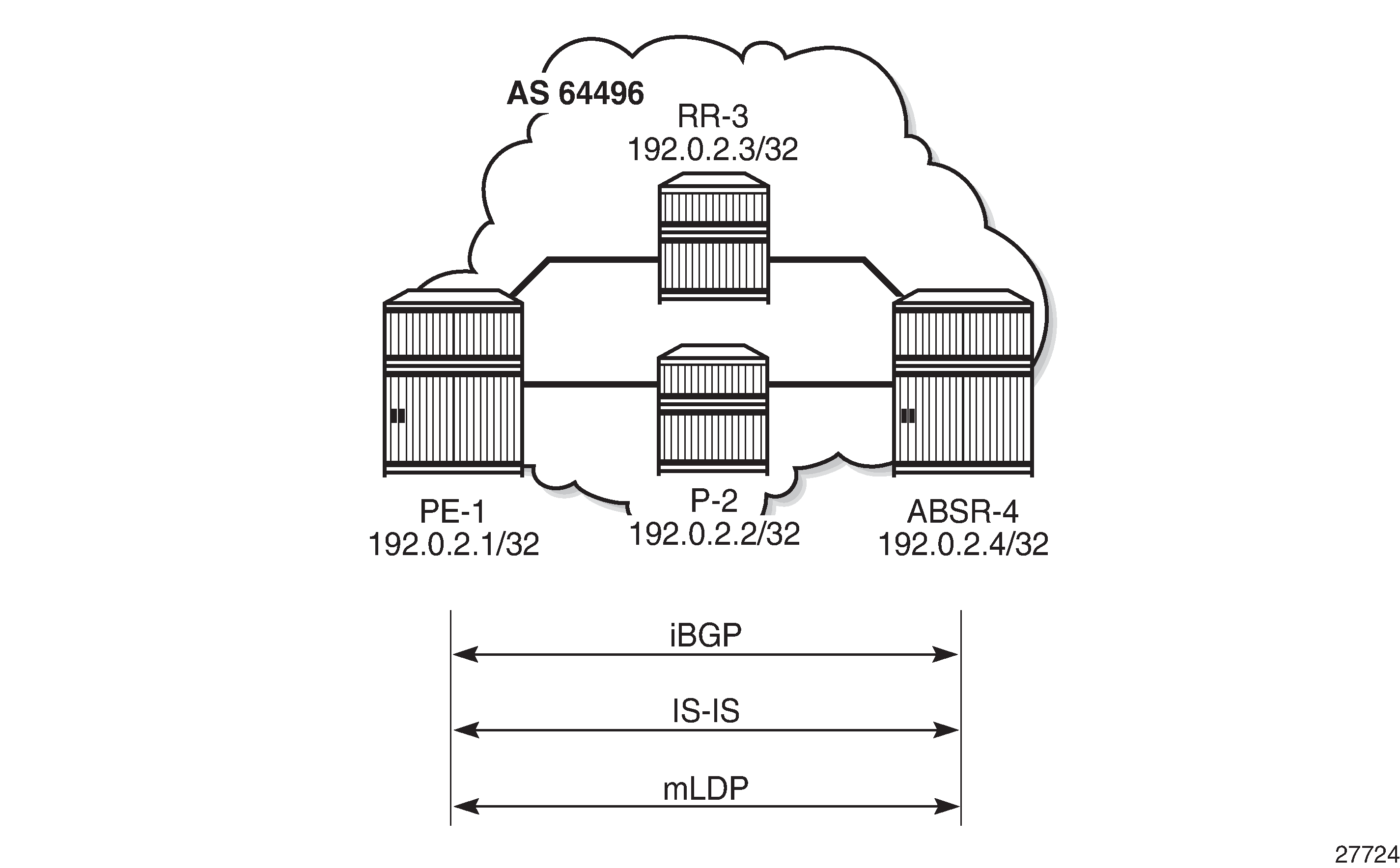
AS 64496 Protocols shows the protocol requirements for AS 64496.
Router Interface and IS-IS Configuration
The first step is to configure the router interfaces and IS-IS as the Interior Gateway Protocol (IGP) in AS 64496.
The router interfaces for PE-1 are configured as follows:
# on PE-1
configure
    router
        interface "int-PE-1-P-2"
            address 192.168.12.1/30
            port 1/1/1
        exit
        interface "int-PE-1-RR-3"
            address 192.168.13.1/30
            port 1/1/2
        exit
        interface "system"
            address 192.0.2.1/32
        exit
    exit
Each interface is configured to run IS-IS as the IGP, as follows. Each router is configured as a level 2 router.
# on PE-1
configure
    router
        isis
            level-capability level-2
            area-id 49.0001
            advertise-passive-only
            level 2
                wide-metrics-only
            exit
            interface "system"
                passive
                no shutdown
            exit
            interface "int-PE-1-P-2"
                interface-type point-to-point
                no shutdown
            exit
            interface "int-PE-1-RR-3"
                interface-type point-to-point
                no shutdown
            exit
            no shutdown
        exit
The configuration for all other nodes in the AS is the same, other than the IP addresses. The IP addresses can be derived from Figure 1.
LDP Configuration
LDP is used as the MPLS protocol and must be enabled on each router interface, except for the VPN RR and the interfaces to the RR, as follows:
# on PE-1
configure
    router
        ldp
            interface-parameters
                interface "int-PE-1-P-2" dual-stack
                    ipv4
                        fec-type-capability
                            p2mp-ipv4 enable
                        exit
                        no shutdown
                    exit
                    no shutdown
                exit
            exit
            no shutdown
        exit
This configuration must be repeated on each of the other routers in the AS. Because LDP is used as the provider tunnel interface for multicast traffic, the previously indicated interfaces must also support P2MP LDP tunnels. Therefore, the FEC type capability for IPv4 P2MP tunnels must be enabled. The default value is enable, but is included in the preceding output for clarity.
BGP Configuration
RR-3 Configuration
RR-3 is the route reflector for the VPN-IPv4 and MVPN-IPv4 address families within AS 64496, and peers with PE-1, but not with ASBR-4 and P-2. The cluster ID is set to ensure that RR-3 is an RR. For supporting inter-AS VPRN model C, PE-3 also peers with RR-7 in AS 64497 for the same address families, through a multi-hop eBGP session.
configure
    router
        autonomous-system 64496
        bgp
            loop-detect discard-route
            min-route-advertisement 1
            rapid-withdrawal
            split-horizon
            rapid-update vpn-ipv4 mvpn-ipv4
            group "EBGP-vpn-mvpn"
                family vpn-ipv4 mvpn-ipv4
                peer-as 64497
                local-address 192.0.2.3
                neighbor 192.0.2.7
                    multihop 10
                exit
            exit
            group "IBGP-vpn-mvpn"
                cluster 192.0.2.3
                peer-as 64496
                neighbor 192.0.2.1
                    family vpn-ipv4 mvpn-ipv4
                exit
            exit
            no shutdown
        exit
ASBR-4 Configuration
Although ASBR-4 is the AS border router for AS 64496 (so that it peers with ASBR-8 in AS 64497), ASBR-4 is also configured as RR for the labeled IPv4 address family within AS 64496, and peers with PE-1, as follows:
configure
    router
        autonomous-system 64496
        bgp
            loop-detect discard-route
            rapid-withdrawal
            split-horizon
            rib-management
                label-ipv4
                    route-table-import "to-AS64497"
                exit
            exit
            group "EBGP-label"
                export "exp-PE-and-RR"
                neighbor 192.168.48.2
                    family label-ipv4
                    peer-as 64497
                    advertise-inactive
                exit
            exit
            group "IBGP-label"
                next-hop-self
                cluster 192.0.2.4
                peer-as 64496
                neighbor 192.0.2.1
                    family label-ipv4
                exit
            exit
            no shutdown
        exit
The policies ensure that the system addresses of the PEs and the RRs are exchanged between AS 64496 and AS 64497. In this example, ASBR-4 generates the labeled routes but pops the label associated with RR-3; see the Pop-Label for /32 Label-IPv4 BGP routes chapter.
configure
    router
        policy-options
            begin
            prefix-list "PE-pfxs"
                prefix 192.0.2.1/32 exact
                prefix 192.0.2.4/32 exact
            exit
            prefix-list "RR-pfxs"
                prefix 192.0.2.3/32 exact
            exit
            policy-statement "exp-PE-plus-RR"
                entry 10
                    from
                        prefix-list "PE-pfxs" "RR-pfxs"
                    exit
                    action accept
                    exit
                exit
            exit
            policy-statement "to-AS64497"
                entry 10
                    from
                        prefix-list "PE-pfxs"
                    exit
                    action accept
                    exit
                exit
                entry 20
                    from
                        prefix-list "RR-pfxs"
                    exit
                    action accept
                        advertise-label pop
                    exit
                exit
            exit
            commit
        exit
PE-1 configuration
PE-1 is a BGP client of RR-3 and ASBR-4, as follows:
configure
    router
        autonomous-system 64496
        bgp
            group "IBGP-lbl"
                peer-as 64496
                neighbor 192.0.2.4
                    family label-ipv4
                exit
            exit
            group "IBGP-vpn-mvpn"
                peer-as 64496
                neighbor 192.0.2.3
                    family vpn-ipv4 mvpn-ipv4
                exit
            exit
            no shutdown
        exit
P-2 does not have any BGP configuration; it participates in the MPLS data plane for switching unicast and multicast customer traffic, and does not have any services defined.
AS 64497
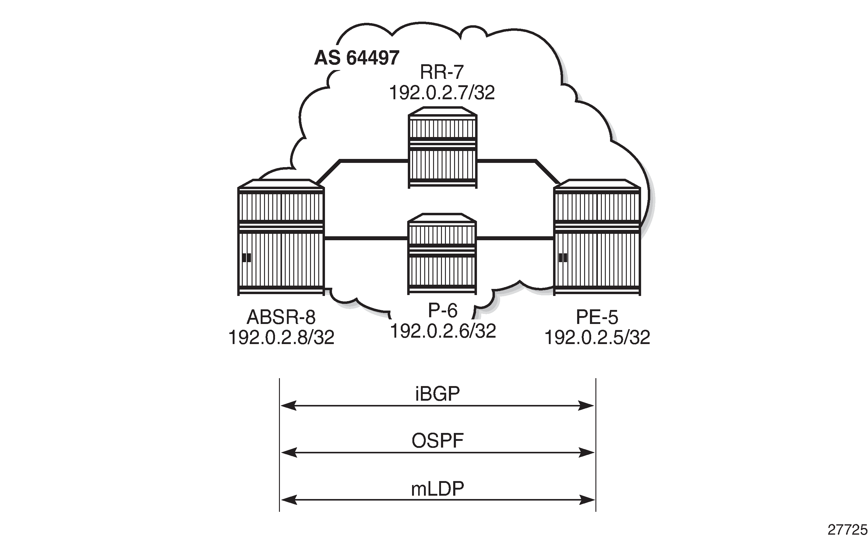
AS 64497 Protocols shows the protocol requirements for AS 64497.
Router Interface and OSPF Configuration
The first step is to configure router interfaces and OSPF on each router shown in AS 64497 Protocols. All router interfaces are members of a single backbone area: area 0.0.0.0.
The following router interfaces are configured on PE-5:
configure
    router
        interface "int-PE-5-P-6"
            address 192.168.56.1/30
            port 1/1/2
        exit
        interface "int-PE-5-RR-7"
            address 192.168.57.1/30
            port 1/1/1
        exit
        interface "system"
            address 192.0.2.5/32
        exit
    exit
exit
On PE-5, OSPF is configured as follows:
configure
    router
        ospf 0
            area 0.0.0.0
                interface "system"
                    no shutdown
                exit
                interface "int-PE-5-P-6"
                    interface-type point-to-point
                    no shutdown
                exit
                interface "int-PE-5-RR-7"
                    interface-type point-to-point
                    no shutdown
                exit
            exit
            no shutdown
        exit
    exit
exit
LDP Configuration
LDP is used as the MPLS protocol and must be enabled on each router interface, except on the RR and the interfaces toward the RR, as follows:
configure
    router
        ldp
            interface-parameters
                interface "int-PE-5-P-6"
                    ipv4
                        fec-type-capability
                            p2mp-ipv4 enable
                        exit
                    exit
                exit
            exit
        exit
    exit
exit
This configuration must be repeated on each of the other routers in the AS, and the FEC type capability for IPv4 P2MP tunnels must again be enabled. The default value is enable, but is included in the preceding output for clarity.
BGP Configuration
The BGP configuration for AS 64497 is mirrored from AS 64497, so the configuration is similar, meaning that RR-7 is RR for VPN and MVPN routes, and ASBR-8 is RR for labeled IPv4 routes, with PE-5 being the client. P-6 is not a BGP client for RR-7 and ASBR-8.
Inter-AS Configuration
Inter-AS Protocols shows the protocols required between ASBR-4 and ASBR-8. The interface addresses are used for the LDP transport and the BGP speaker peer addresses.
LDP Peering
LDP is configured as the MPLS protocol between ASBR-4 and ASBR-8. On ASBR-4, the interface toward ASBR-8 has LDP enabled, as follows. The interface address should be used as the LDP transport address because the system address of ASBR-8 is not known to ASBR-4.
# on ASBR-4
configure
    router
        ldp
            interface-parameters
                interface "int-ASBR-4-ASBR-8" dual-stack
                    ipv4
                        fec-type-capability
                            p2mp-ipv4 enable
                        exit
                        transport-address interface
                        no shutdown
                    exit
                    no shutdown
                exit
            exit
            no shutdown
        exit
    exit
exit
The P2MP FEC type capability for P2MP LDP is shown. This is the default value.
For completeness, the LDP configuration on ASBR-8 for the interface toward ASBR-4 is as follows:
configure
    router
        ldp
            interface-parameters
                interface "int-ASBR-8-ASBR-4" dual-stack
                    ipv4
                        fec-type-capability
                            p2mp-ipv4 enable
                        exit
                        transport-address interface
                    exit
                exit
                    no shutdown
                exit
            no shutdown
        exit
    exit
exit
The LDP session is successfully established at ASBR-4, as follows:
*A:ASBR-4# show router ldp session 192.0.2.8

==============================================================================
LDP IPv4 Sessions
==============================================================================
Peer LDP Id         Adj Type  State         Msg Sent  Msg Recv  Up Time
------------------------------------------------------------------------------
192.0.2.8:0         Link      Established   2258      2260      0d 01:40:07
------------------------------------------------------------------------------
No. of IPv4 Sessions: 1
==============================================================================

===============================================================================
LDP IPv6 Sessions
===============================================================================
Peer LDP Id
 Adj Type            State          Msg Sent       Msg Recv       Up Time
-------------------------------------------------------------------------------
No Matching Entries Found
===============================================================================
*A:ASBR-4#
For completeness, the LDP session from ASBR-8 toward ASBR-4 is shown in the following output:
*A:ASBR-8# show router ldp session 192.0.2.4

==============================================================================
LDP IPv4 Sessions
==============================================================================
Peer LDP Id         Adj Type  State         Msg Sent  Msg Recv  Up Time
------------------------------------------------------------------------------
192.0.2.4:0         Link      Established   2272      2273      0d 01:40:43
------------------------------------------------------------------------------
No. of IPv4 Sessions: 1
==============================================================================

===============================================================================
LDP IPv6 Sessions
===============================================================================
Peer LDP Id
 Adj Type            State          Msg Sent       Msg Recv       Up Time
-------------------------------------------------------------------------------
No Matching Entries Found
===============================================================================
*A:ASBR-8#
When a label mapping message is received for an LDP FEC prefix, the next-hop for a FEC prefix is resolved in the routing table. The FEC is installed in the Label Information Base (LIB) if the next-hop matches a /32 route table entry.
The local interface configuration will result in a route being installed with a subnet mask matching the interface configuration. In this case, the ASBR-to-ASBR route is 192.168.45.0/30.
For LDP to resolve the LDP FEC egress next-hop on ASBR-4, a /32 route matching the egress next-hop address is required in the FIB. For that purpose, on ASBR-4, a static route is configured for the /32 address located on ASBR-8, as follows:
# on ASBR-4
configure
    router
        static-route-entry 192.168.48.2/32
            next-hop 192.168.48.2
                no shutdown
            exit
        exit
    exit
exit
Similarly, a static route on ASBR-8 is configured for the /32 address located on ASBR-4, as follows:
# on ASBR-8
configure
    router
        static-route-entry 192.168.48.1/32
            next-hop 192.168.48.1
                no shutdown
            exit
        exit
    exit
exit
The following output shows that the static route is installed in the ASBR-4 Routing Information Base (RIB):
*A:ASBR-4# show router route-table protocol static
===============================================================================
Route Table (Router: Base)
===============================================================================
Dest Prefix[Flags]                            Type    Proto     Age        Pref
      Next Hop[Interface Name]                                    Metric
-------------------------------------------------------------------------------
192.168.48.2/32                               Remote  Static    01h39m26s  5
       192.168.48.2                                                 1
-------------------------------------------------------------------------------
No. of Routes: 1
Flags: n = Number of times nexthop is repeated
       B = BGP backup route available
       L = LFA nexthop available
       S = Sticky ECMP requested
===============================================================================
*A:ASBR-4#
eBGP Peering - ASBR-4 to ASBR-8
The following shows the eBGP peering configuration for ASBR-4. The peer address is the interface address of ASBR-8.
configure
    router
        autonomous-system 64496
        bgp
            group "EBGP-label"
                export "exp-PE-plus-RR"
                neighbor 192.168.48.2
                    family label-ipv4
                    peer-as 64497
                    advertise-inactive
                exit
            exit
Similarly, the BGP configuration for ASBR-8 peering toward ASBR-4 is as follows:
configure
    router
        autonomous-system 64496
        bgp
            group "EBGP-lbl"
                export "exp-PE-plus-RR"
                neighbor 192.168.48.1
                    family label-ipv4
                    peer-as 64496
                    advertise-inactive
                exit
            exit
The BGP peering session between ASBR-4 and ASBR-8 is verified as follows. In this example, only labeled IPv4 routes are exchanged.
*A:ASBR-4# show router bgp summary group "EBGP-label"
===============================================================================
 BGP Router ID:192.0.2.4        AS:64496       Local AS:64496
===============================================================================
BGP Admin State         : Up          BGP Oper State              : Up
Total Peers             : 1

Total IPv4 Remote Rts   : 0           Total IPv4 Rem. Active Rts  : 0
Total IPv6 Remote Rts   : 0           Total IPv6 Rem. Active Rts  : 0
Total IPv4 Backup Rts   : 0           Total IPv6 Backup Rts       : 0
Total LblIpv4 Rem Rts   : 2           Total LblIpv4 Rem. Act Rts  : 2
Total LblIpv6 Rem Rts   : 0           Total LblIpv6 Rem. Act Rts  : 0
Total LblIpv4 Bkp Rts   : 0           Total LblIpv6 Bkp Rts       : 0

Total VPN-IPv4 Rem. Rts : 0           Total VPN-IPv4 Rem. Act. Rts: 0
Total VPN-IPv6 Rem. Rts : 0           Total VPN-IPv6 Rem. Act. Rts: 0
Total VPN-IPv4 Bkup Rts : 0           Total VPN-IPv6 Bkup Rts     : 0

Total MVPN-IPv4 Rem Rts : 0           Total MVPN-IPv4 Rem Act Rts : 0
Total MVPN-IPv6 Rem Rts : 0           Total MVPN-IPv6 Rem Act Rts : 0
Total MDT-SAFI Rem Rts  : 0           Total MDT-SAFI Rem Act Rts  : 0
Total McIPv4 Remote Rts : 0           Total McIPv4 Rem. Active Rts: 0
Total McIPv6 Remote Rts : 0           Total McIPv6 Rem. Active Rts: 0
Total McVpnIPv4 Rem Rts : 0           Total McVpnIPv4 Rem Act Rts : 0
Total McVpnIPv6 Rem Rts : 0           Total McVpnIPv6 Rem Act Rts : 0

Total EVPN Rem Rts      : 0           Total EVPN Rem Act Rts      : 0
Total L2-VPN Rem. Rts   : 0           Total L2VPN Rem. Act. Rts   : 0
Total MSPW Rem Rts      : 0           Total MSPW Rem Act Rts      : 0
Total RouteTgt Rem Rts  : 0           Total RouteTgt Rem Act Rts  : 0
Total FlowIpv4 Rem Rts  : 0           Total FlowIpv4 Rem Act Rts  : 0
Total FlowIpv6 Rem Rts  : 0           Total FlowIpv6 Rem Act Rts  : 0
Total Link State Rem Rts: 0           Total Link State Rem Act Rts: 0

===============================================================================
BGP Summary
===============================================================================
Legend : D - Dynamic Neighbor
===============================================================================
Neighbor
Description
                   AS PktRcvd InQ  Up/Down   State|Rcv/Act/Sent (Addr Family)
                      PktSent OutQ
-------------------------------------------------------------------------------
192.168.48.2
               64497      220    0 01h41m10s 2/2/2 (Lbl-IPv4)
                          210    0
-------------------------------------------------------------------------------
*A:ASBR-4#
eBGP Peering - RR-3 to RR-7
The following shows the configuration required for establishing an eBGP multi-hop peering session from RR-3 to RR-7. The peer address is the system address of RR-7.
# on RR-3
configure
    router
        static-route-entry 192.0.2.7/32
            indirect 192.0.2.4
                tunnel-next-hop
                    resolution disabled
                exit
                no shutdown
            exit
        exit
        bgp
            loop-detect discard-route
            split-horizon
            rapid-update vpn-ipv4 mvpn-ipv4
            group "EBGP-vpn-mvpn"
                family vpn-ipv4 mvpn-ipv4
                peer-as 64497
                neighbor 192.0.2.7
                    multihop 10
                exit
            exit
            ---snip---
            no shutdown
        exit
    exit
Similarly, the BGP configuration for RR-7 multi-hop peering with RR-3 is as follows:
# on RR-7
configure
    router
        static-route-entry 192.0.2.3/32
            indirect 192.0.2.8
                tunnel-next-hop
                    resolution disabled
                exit
                no shutdown
            exit
        exit
        bgp
            loop-detect discard-route
            split-horizon
            rapid-update vpn-ipv4 mvpn-ipv4
            group "EBGP-vpn-mvpn"
                family vpn-ipv4 mvpn-ipv4
                peer-as 64496
                neighbor 192.0.2.3
                    multihop 10
                exit
            exit
            ---snip---
            no shutdown
        exit
    exit
This peering session is verified as follows. Only VPN-IPv4 and MVPN-IPv4 routes are exchanged.
*A:RR-3# show router bgp summary group "EBGP-vpn-mvpn"
===============================================================================
 BGP Router ID:192.0.2.3        AS:64496       Local AS:64496
===============================================================================
BGP Admin State         : Up          BGP Oper State              : Up
Total Peers             : 1

Total IPv4 Remote Rts   : 0           Total IPv4 Rem. Active Rts  : 0
Total IPv6 Remote Rts   : 0           Total IPv6 Rem. Active Rts  : 0
Total IPv4 Backup Rts   : 0           Total IPv6 Backup Rts       : 0
Total LblIpv4 Rem Rts   : 0           Total LblIpv4 Rem. Act Rts  : 0
Total LblIpv6 Rem Rts   : 0           Total LblIpv6 Rem. Act Rts  : 0
Total LblIpv4 Bkp Rts   : 0           Total LblIpv6 Bkp Rts       : 0

Total VPN-IPv4 Rem. Rts : 1           Total VPN-IPv4 Rem. Act. Rts: 0
Total VPN-IPv6 Rem. Rts : 0           Total VPN-IPv6 Rem. Act. Rts: 0
Total VPN-IPv4 Bkup Rts : 0           Total VPN-IPv6 Bkup Rts     : 0

Total MVPN-IPv4 Rem Rts : 2           Total MVPN-IPv4 Rem Act Rts : 0
Total MVPN-IPv6 Rem Rts : 0           Total MVPN-IPv6 Rem Act Rts : 0
Total MDT-SAFI Rem Rts  : 0           Total MDT-SAFI Rem Act Rts  : 0
Total McIPv4 Remote Rts : 0           Total McIPv4 Rem. Active Rts: 0
Total McIPv6 Remote Rts : 0           Total McIPv6 Rem. Active Rts: 0
Total McVpnIPv4 Rem Rts : 0           Total McVpnIPv4 Rem Act Rts : 0
Total McVpnIPv6 Rem Rts : 0           Total McVpnIPv6 Rem Act Rts : 0

Total EVPN Rem Rts      : 0           Total EVPN Rem Act Rts      : 0
Total L2-VPN Rem. Rts   : 0           Total L2VPN Rem. Act. Rts   : 0
Total MSPW Rem Rts      : 0           Total MSPW Rem Act Rts      : 0
Total RouteTgt Rem Rts  : 0           Total RouteTgt Rem Act Rts  : 0
Total FlowIpv4 Rem Rts  : 0           Total FlowIpv4 Rem Act Rts  : 0
Total FlowIpv6 Rem Rts  : 0           Total FlowIpv6 Rem Act Rts  : 0
Total Link State Rem Rts: 0           Total Link State Rem Act Rts: 0

===============================================================================
BGP Summary
===============================================================================
Legend : D - Dynamic Neighbor
===============================================================================
Neighbor
Description
                   AS PktRcvd InQ  Up/Down   State|Rcv/Act/Sent (Addr Family)
                      PktSent OutQ
-------------------------------------------------------------------------------
192.0.2.7
               64497      184    0 01h28m14s 1/0/1 (VpnIPv4)
                          185    0           2/0/2 (MvpnIPv4)
-------------------------------------------------------------------------------
*A:RR-3#
VPRN Configuration
The VPRN service configuration for PE-1 and PE-5 is as follows:
# at PE-1
configure
    service
        vprn 1 customer 1 create
            route-distinguisher 64496:1
            auto-bind-tunnel
                resolution-filter
                    ldp
                exit
                resolution filter
            exit
            vrf-target target:64496:1
            interface "int-PE-1-VPRN-1-H-1" create
                address 10.1.11.1/24
                sap 1/2/1 create
                exit
                no shutdown
            exit
            igmp
                interface "int-PE-1-VPRN-1-H-1"
                    no shutdown
                exit
                no shutdown
            exit
            pim
                shutdown
            exit
            mvpn
                auto-discovery default
                c-mcast-signaling bgp
                provider-tunnel
                    inclusive
                        mldp
                            no shutdown
                        exit
                    exit
                exit
                vrf-target unicast
                exit
            exit
            no shutdown
        exit
    exit
exit
# at PE-5
configure
    service
        vprn 1 customer 1 create
            route-distinguisher 64497:1
            auto-bind-tunnel
                resolution-filter
                    ldp
                exit
                resolution filter
            exit
            vrf-target target:64496:1
            interface "int-PE-5-VPRN-1-source" create
                address 10.1.51.1/24
                sap 1/2/1 create
                exit
            exit
            pim
                apply-to all
                no shutdown
            exit
            mvpn
                auto-discovery default
                c-mcast-signaling bgp
                mdt-type sender-only
                provider-tunnel
                    inclusive
                        mldp
                            no shutdown
                        exit
                    exit
                exit
                vrf-target unicast
                exit
            exit
            no shutdown
        exit
    exit
exit
Route Policy for MVPN Routes
The use of non-segmented LDP provider tunnels requires that intra-AD routes must be advertised across the AS boundary between PEs. Each intra-AD route generated by a PE that is a member of an MVPN contains the well-known community "No-Export", which prevents a BGP speaker from advertising the route across an AS boundary to another external BGP speaker.
In inter-AS model C, the RRs must support the MVPN address family. If the RR receives an intra-AD route containing the No-Export community, this route will not be advertised to any external peer. A route policy is required to remove the No-Export community before the route can be advertised across the AS boundary to a BGP speaker that has negotiated the MVPN address family capability.
In the following example, a RemNoExport policy is defined, which will remove the No-Export community, using the community remove action as a default action:
# at PE-1 and PE-5
configure
    router
        policy-options
            begin
            community "NoExport" members "no-export"
            policy-statement "RemNoExport"
                default-action accept
                    community remove "NoExport"
                exit
            exit
            commit
        exit
    exit
exit
This policy is applied as an export policy, so that the No-Export community is removed from all intra-AD routes advertised as updates to internal peers. The vpn-apply-export command must be included to ensure that the export policy is applied to routes belonging to VPN address families; in this case, MVPN-IPv4 routes.
# at PE-5
configure
    router
        bgp
            group "IBGP-vpn-mvpn"
                vpn-apply-export
                export "RemNoExport"
                peer-as 64497
                neighbor 192.0.2.7
                    family vpn-ipv4 mvpn-ipv4
                exit
            exit
            no shutdown
        exit
    exit
exit
This policy should also be configured and applied on PE-1, so that intra-AD routes can be exported from MVPN PEs in AS 64496 to AS 64497.
Verification
BGP MVPN Intra-AD Route Propagation
BGP MVPN Intra-AD Route Advertisement shows the propagation of the BGP MVPN intra-AD route from PE-5 to PE-1 across the AS boundary. The original route has the No-Export community removed at PE-5, due to the export route policy applied. RR-3 receives the route via RR-7 and reflects it to PE-1. The BGP next-hop attribute is changed by RR-7 to its system address: 192.0.2.7. RR-3 reflects the intra-AD route to PE-1, also changing the BGP next-hop attribute to its system address: 192.0.2.3.
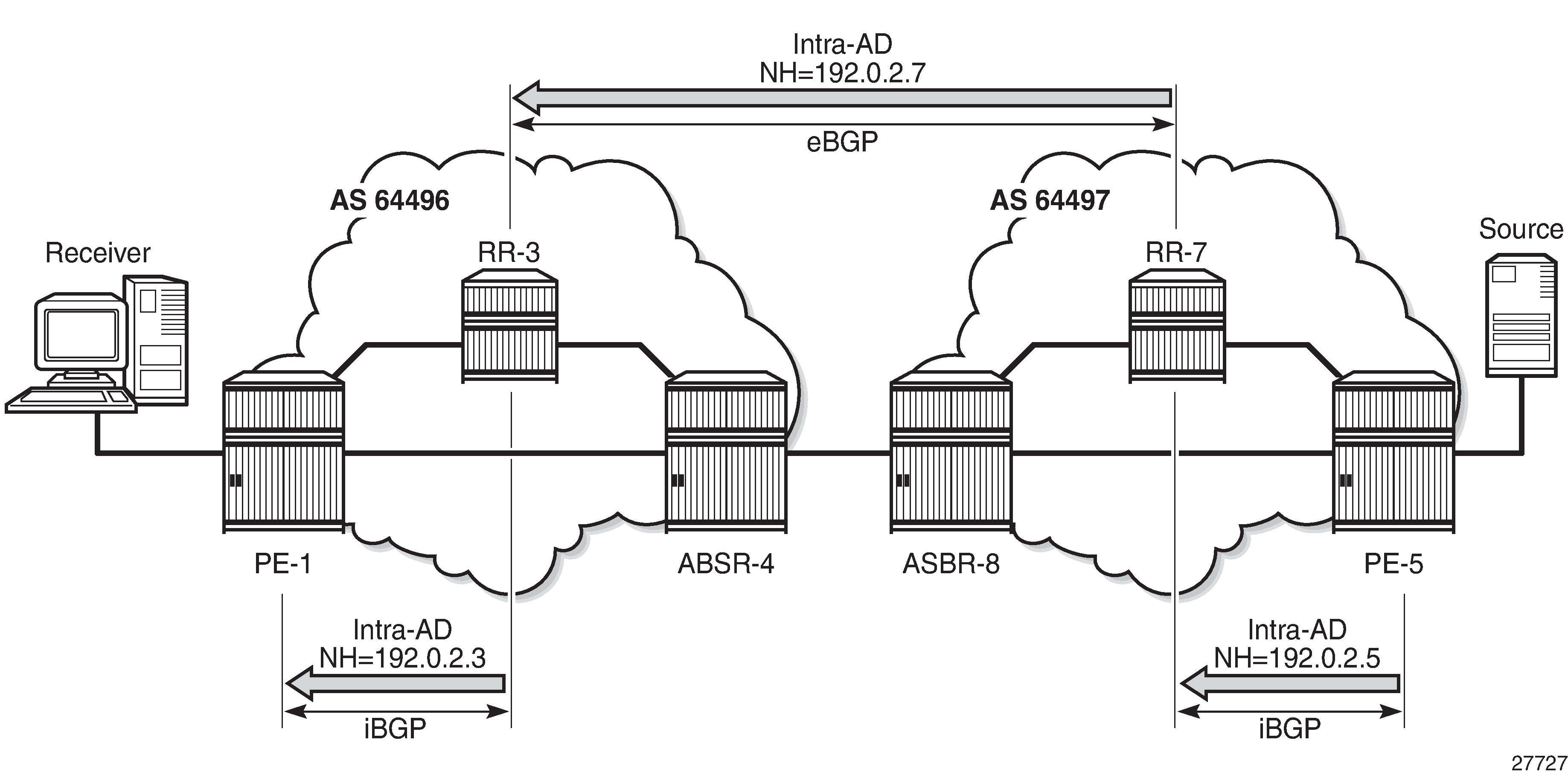
PE-1 receives the route, and will import the route into VPRN 1 because the route target extended community matches the community configured in the MVPN context of the VPRN. PE-1 now uses the PTA contained within the intra-AD route to instantiate the provider tunnel.
The following output shows details of the MVPN intra-AD route received by PE-1, generated by PE-5:
*A:PE-1# show router bgp routes mvpn-ipv4 type intra-ad originator-ip 192.0.2.5 hunt
===============================================================================
 BGP Router ID:192.0.2.1        AS:64496       Local AS:64496
===============================================================================
 Legend -
 Status codes  : u - used, s - suppressed, h - history, d - decayed, * - valid
                 l - leaked, x - stale, > - best, b - backup, p - purge
 Origin codes  : i - IGP, e - EGP, ? - incomplete

===============================================================================
BGP MVPN-IPv4 Routes
===============================================================================
-------------------------------------------------------------------------------
RIB In Entries
-------------------------------------------------------------------------------
Route Type     : Intra-Ad
Route Dist.    : 64497:1
Originator IP  : 192.0.2.5
Nexthop        : 192.0.2.3
Path Id        : None
From           : 192.0.2.3
Res. Nexthop   : 0.0.0.0
Local Pref.    : 100                    Interface Name : NotAvailable
Aggregator AS  : None                   Aggregator     : None
Atomic Aggr.   : Not Atomic             MED            : None
AIGP Metric    : None
Connector      : None
Community      : target:64496:1
Cluster        : No Cluster Members
Originator Id  : None                   Peer Router Id : 192.0.2.3
Flags          : Used  Valid  Best  IGP
Route Source   : Internal
AS-Path        : 64497
Route Tag      : 0
Neighbor-AS    : 64497
Orig Validation: N/A
Source Class   : 0                      Dest Class     : 0
Add Paths Send : Default
Last Modified  : 02h00m06s
VPRN Imported  :  1
-------------------------------------------------------------------------------
PMSI Tunnel Attributes :
Tunnel-type    : LDP P2MP LSP
Flags          : Type: RNVE(0) BM: 0 U: 0 Leaf: not required
MPLS Label     : 0
Root-Node      : 192.0.2.5              LSP-ID         : 8193
-------------------------------------------------------------------------------

-------------------------------------------------------------------------------
RIB Out Entries
-------------------------------------------------------------------------------
-------------------------------------------------------------------------------
Routes : 1
===============================================================================
*A:PE-1#
P2MP LDP LSP Signaling
The PTA lists the tunnel type as an LDP P2MP LSP. A P2MP label mapping message is originated at PE-1, with LSP ID 8193, with inner-root PE-5 and outer-root ASBR-4.
The intra-AD MVPN route is used to determine the path of the label mapping message from PE-1 toward PE-5. This is similar to the unicast routing case, where a VPN-IPv4 labeled route is used to determine the path to the source.
The BGP next-hop of the intra-AD route is the system address of ASBR-4, so this can be used as the root address of the mLDP LSP, and the actual root can be contained inside the label mapping message as an inner root. The inner root becomes an opaque value that is known to the originator and receiver of the label mapping message. PE-1 thus generates a recursive-opaque type=7 FEC: <ASBR-4, <PE-5, P2MP-id>>.
P2MP LDP Label Mapping shows the path taken by the label mapping message from PE-1 to PE-5.
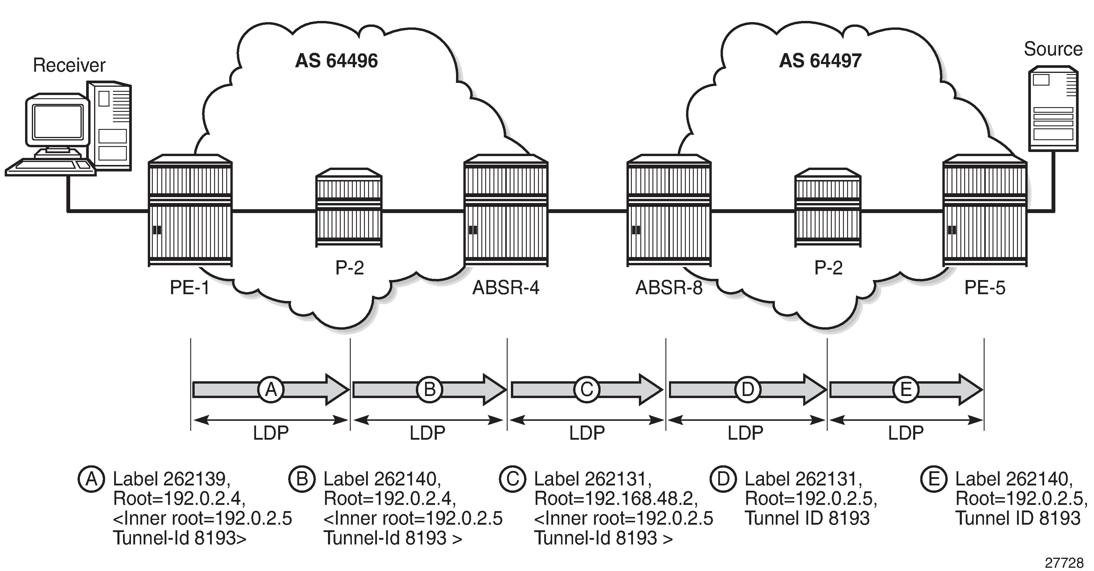
P-2 does not have a BGP-LBL route to reach PE-5, but has an IGP route to reach the outer root ASBR-4. The label mapping message is forwarded from PE-1 to ASBR-4 via P-2. At each hop, a label is allocated and a label binding entry is created. In the following sections, the debug outputs are achieved using the following debug command:
debug
    router "Base"
        ldp
            peer <peer-ip-address>
                packet
                    label detail
                exit
            exit
        exit
    exit
exit
where <peer-ip-address> is the system address of the LDP peer.
LDP Hop PE-1 to P-2
The following output shows a debug of the P2MP label mapping message sent from PE-1 to P-2 upon receipt of the BGP MVPN intra-AD route:
5 2018/05/25 09:47:20.085 UTC MINOR: DEBUG #2001 Base LDP
"LDP: LDP
Send Label Mapping packet (msgId 125) to 192.0.2.2:0
Protocol version = 1
Label 262139 advertised for the following FECs
P2MP:root = 192.0.2.4, T: 7, L: 17 (InnerRoot: 192.0.2.5 T: 1, L: 4, TunnelId: 8193)
"
The advertised label is 262139: the ingress label at PE-1. The P2MP root address is the next hop for the BGP-LBL route to reach PE-5 (192.0.2.5), namely ASBR-4 (192.0.2.4). T: 7 signifies that the FEC type is 7, GRT-recursive FEC, and L: 17 is the length of the opaque value. The opaque value contains the inner root 192.0.2.5 and a second opaque value: a type 1 (T: 1) generic FEC of length L = 4 bytes, containing the tunnel ID 8193.
The format of the type 7 opaque value aligns with the representation in Table 1:
<ASBR-4, Opaque type 7 <PE-5, Opaque type 1 <Tunnel-ID> > >.
The LDP binding table of PE-1 is shown in the following output:
*A:PE-1# show router ldp bindings active p2mp ipv4 opaque-type grt-recursive

===============================================================================
LDP Bindings (IPv4 LSR ID 192.0.2.1)
             (IPv6 LSR ID ::)
===============================================================================
Label Status:
        U - Label In Use, N - Label Not In Use, W - Label Withdrawn
        WP - Label Withdraw Pending, BU - Alternate For Fast Re-Route
        e - Label ELC
FEC Flags:
        LF - Lower FEC, UF - Upper FEC, M - Community Mismatch, BA - ASBR Backup FEC
===============================================================================
LDP GRT Recursive with Generic IPv4 P2MP Bindings (Active)
===============================================================================
P2MP-Id                                     Interface
RootAddr                                    Op              IngLbl    EgrLbl
InnerRootAddr
EgrNH                                       EgrIf/LspId
-------------------------------------------------------------------------------
8193                                        73728
192.0.2.4                                   Pop             262139      --
192.0.2.5
  --                                          --

-------------------------------------------------------------------------------
No. of GRT Recursive with Generic IPv4 P2MP Active Bindings: 1
===============================================================================
*A:PE-1#
The preceding output shows the GRT-recursive FEC binding with both the root address of ASBR-4 and the inner root of PE-5.
LDP Hop P-2 to ASBR-4
At P-2, the label mapping messages received from PE-1 and advertised toward ASBR-4 are shown in the following output:
1 2018/05/25 09:47:20.083 UTC MINOR: DEBUG #2001 Base LDP
"LDP: LDP
Recv Label Mapping packet (msgId 125) from 192.0.2.1:0
Protocol version = 1
Label 262139 advertised for the following FECs
P2MP:root = 192.0.2.4, T: 7, L: 17 (InnerRoot: 192.0.2.5 T: 1, L: 4, TunnelId: 8193)
"
2 2018/05/25 09:47:20.083 UTC MINOR: DEBUG #2001 Base LDP
"LDP: LDP
Send Label Mapping packet (msgId 124) to 192.0.2.4:0
Protocol version = 1
Label 262140 advertised for the following FECs
P2MP:root = 192.0.2.4, T: 7, L: 17 (InnerRoot: 192.0.2.5 T: 1, L: 4, TunnelId: 8193)
"
The received message matches the advertised label from PE-1, and the label mapping message toward ASBR-4 (192.0.2.4) is again a GRT-recursive FEC type.
The following output shows the LDP label mapping for the GRT-recursive FEC at P-2:
*A:P-2# show router ldp bindings active p2mp ipv4 opaque-type grt-recursive

===============================================================================
LDP Bindings (IPv4 LSR ID 192.0.2.2)
             (IPv6 LSR ID ::)
===============================================================================
Label Status:
        U - Label In Use, N - Label Not In Use, W - Label Withdrawn
        WP - Label Withdraw Pending, BU - Alternate For Fast Re-Route
        e - Label ELC
FEC Flags:
        LF - Lower FEC, UF - Upper FEC, M - Community Mismatch, BA - ASBR Backup FEC
===============================================================================
LDP GRT Recursive with Generic IPv4 P2MP Bindings (Active)
===============================================================================
P2MP-Id                                     Interface
RootAddr                                    Op              IngLbl    EgrLbl
InnerRootAddr
EgrNH                                       EgrIf/LspId
-------------------------------------------------------------------------------
8193                                        Unknw
192.0.2.4                                   Swap            262140    262139
192.0.2.5
192.168.12.1                                1/1/2

-------------------------------------------------------------------------------
No. of GRT Recursive with Generic IPv4 P2MP Active Bindings: 1
===============================================================================
*A:P-2#
LDP Hop ASBR-4 to ASBR-8
ASBR-4 is the root of the mLDP tree in AS 64496. Upon receipt of an mLDP label mapping message containing this FEC element, ASBR-4 recognizes that it is the root and that the opaque value is a GRT-recursive opaque value. ASBR-4 parses the GRT-recursive opaque value and extracts the root value: PE-5.
ASBR-4 checks RTM for a route to reach the inner-root (PE-5), which is a BGP-LBL route with next-hop ASBR-8.
ASBR-4 will create an mLDP mapping message containing a GRT-recursive FEC whose opaque value has the inner root address of PE-5, and a root address of ASBR-8.
The following output shows the label mapping messages at ASBR-4:
1 2018/05/25 09:47:20.086 UTC MINOR: DEBUG #2001 Base LDP
"LDP: LDP
Recv Label Mapping packet (msgId 124) from 192.0.2.2:0
Protocol version = 1
Label 262140 advertised for the following FECs
P2MP: root = 192.0.2.4, T: 7, L: 17 (InnerRoot: 192.0.2.5 T: 1, L: 4, TunnelId: 8193)
"
2 2018/05/25 09:47:20.086 UTC MINOR: DEBUG #2001 Base LDP
"LDP: Binding
Sending Label mapping label 262131 for P2MP: root = 192.168.48.2, T: 7,
    L: 17 (InnerRoot: 192.0.2.5 T: 1, L: 4, TunnelId: 8193)
    to peer 192.0.2.8:0."
3 2018/05/25 09:47:20.086 UTC MINOR: DEBUG #2001 Base LDP
"LDP: LDP
Send Label Mapping packet (msgId 82) to 192.0.2.8:0
Protocol version = 1
Label 262131 advertised for the following FECs
P2MP: root = 192.168.48.2, T: 7, L: 17 (InnerRoot: 192.0.2.5 T: 1,
    L: 4, TunnelId: 8193)
The label mapping message uses a format of the opaque type listed in mLDP Message Opaque Value Types in MVPN inter-AS Model C , where the new root is now ASBR-8, and the inner root address remains the PE-5 system address:
<ASBR-8, Opaque type 7 <PE-5, Opaque type 1 <Tunnel-ID> > >
At ASBR-4, the root changes from ASBR-4 to ASBR-8. ASBR-4 essentially becomes a leaf node with root at ASBR-8.
The following output shows the label binding output at ASBR-4:
*A:ASBR-4# show router ldp bindings active p2mp ipv4 opaque-type grt-recursive
===============================================================================
LDP Bindings (IPv4 LSR ID 192.0.2.4)
             (IPv6 LSR ID ::)
===============================================================================
Label Status:
        U - Label In Use, N - Label Not In Use, W - Label Withdrawn
        WP - Label Withdraw Pending, BU - Alternate For Fast Re-Route
        e - Label ELC
FEC Flags:
        LF - Lower FEC, UF - Upper FEC, M - Community Mismatch, BA - ASBR Backup FEC
===============================================================================
LDP GRT Recursive with Generic IPv4 P2MP Bindings (Active)
===============================================================================
P2MP-Id                                     Interface
RootAddr                                    Op              IngLbl    EgrLbl
InnerRootAddr
EgrNH                                       EgrIf/LspId
-------------------------------------------------------------------------------
8193                                        Unknw
192.0.2.4 (LF)                              Push              --      262140
192.0.2.5
192.168.24.1                                1/1/2
8193                                        Unknw
192.168.48.2 (UF)                           Swap            262131    Stitched
192.0.2.5
  --                                          --
-------------------------------------------------------------------------------
No. of GRT Recursive with Generic IPv4 P2MP Active Bindings: 2
===============================================================================
*A:ASBR-4#
The label binding message received from the downstream router P-2 is known as the Lower FEC (LF). The label binding message forwarded to ASBR-8 has allocated a label and is stored as the Upper FEC (UF).
To create a non-segmented mLDP LSP, a label swap action must occur at ASBR-4, where the leaf of the P2MP LSP that has a root at ASBR-8 must be stitched to the P2MP LSP that has a root at ASBR-4 and leaf at PE-1. To achieve this, the UF label is swapped with the LF label. This stitching action is shown in the EgrLbl field of the UF entry.
LDP Hop ASBR-8 to P-6
ASBR-8 receives the label mapping message from ASBR-4. This contains a label mapping plus the opaque value with a GRT-recursive FEC type 7. The root address is a local address, so the recursive FEC is parsed and the root address of PE-5 is extracted.
1 2018/05/25 09:47:20.087 UTC MINOR: DEBUG #2001 Base LDP
"LDP: LDP
Recv Label Mapping packet (msgId 82) from 192.0.2.4:0
Protocol version = 1
Label 262131 advertised for the following FECs
P2MP: root = 192.168.48.2, T: 7, L: 17 (InnerRoot: 192.0.2.5 T: 1,
                                                       L: 4, TunnelId: 8193)
"
ASBR-8 has an IGP route to the PE-5 address (192.0.2.5) in the forwarding table.
Therefore, ASBR-8 will construct an mLDP label mapping message with FEC element containing the address of PE-5 as the root address. This is shown in the following output, where the opaque type is type 1. The opaque value is the tunnel ID contained in the original intra-AD MVPN route, which was contained int the lower FEC received from ASBR-4.
2 2018/05/25 09:47:20.087 UTC MINOR: DEBUG #2001 Base LDP
"LDP: LDP
Send Label Mapping packet (msgId 80) to 192.0.2.6:0
Protocol version = 1
Label 262131 advertised for the following FECs
P2MP: root = 192.0.2.5, T: 1, L: 4, TunnelId: 8193
"
This aligns with the representation for generic FEC type 1 from Table 1:
<PE-5 Opaque type 1 <Tunnel-ID> >.
The following output taken from ASBR-8 shows the stitching of the recursive label mapping received from ASBR-4 to the generic IPv4 label mapping sent to P-6. The LF label received from ASBR-4 (262131) is stitched to the UF label (262131) via the common root address of 192.0.2.5.
*A:ASBR-8# show router ldp bindings active p2mp ipv4

===============================================================================
LDP Bindings (IPv4 LSR ID 192.0.2.8)
             (IPv6 LSR ID ::)
===============================================================================
Label Status:
        U - Label In Use, N - Label Not In Use, W - Label Withdrawn
        WP - Label Withdraw Pending, BU - Alternate For Fast Re-Route
        e - Label ELC
FEC Flags:
        LF - Lower FEC, UF - Upper FEC, M - Community Mismatch, BA - ASBR Backup FEC
===============================================================================
LDP Generic IPv4 P2MP Bindings (Active)
===============================================================================
P2MP-Id                                     Interface
RootAddr                                    Op              IngLbl    EgrLbl
EgrNH                                       EgrIf/LspId
-------------------------------------------------------------------------------
8193                                        Unknw
192.0.2.5 (UF)                              Swap            262131    Stitched
  --                                          --

-------------------------------------------------------------------------------
No. of Generic IPv4 P2MP Active Bindings: 1
===============================================================================

---snip---

===============================================================================

===============================================================================
LDP GRT Recursive with Generic IPv4 P2MP Bindings (Active)
===============================================================================
P2MP-Id                                     Interface
RootAddr                                    Op              IngLbl    EgrLbl
InnerRootAddr
EgrNH                                       EgrIf/LspId
-------------------------------------------------------------------------------
8193                                        Unknw
192.168.48.2 (LF)                           Push              --      262131
192.0.2.5
192.168.48.1                                1/1/3

-------------------------------------------------------------------------------
No. of GRT Recursive with Generic IPv4 P2MP Active Bindings: 1
===============================================================================
*A:ASBR-8#
LDP Hop P-6 to PE-5
At P-6, the label mapping messages received from ASBR-8 and advertised toward PE-5 are shown in the following output:
1 2018/05/25 09:47:20.088 UTC MINOR: DEBUG #2001 Base LDP
"LDP: LDP
Recv Label Mapping packet (msgId 12) from 192.0.2.8:0
Protocol version = 1
Label 262131 advertised for the following FECs
P2MP: root = 192.0.2.5, T: 1, L: 4, TunnelId: 8193
"
2 2018/05/25 09:47:20.089 UTC MINOR: DEBUG #2001 Base LDP
"LDP: LDP
Send Label Mapping packet (msgId 12) to 192.0.2.5:0
Protocol version = 1
Label 262140 advertised for the following FECs
P2MP: root = 192.0.2.5, T: 1, L: 4, TunnelId: 8193
"
The following output on P-6 shows the LDP label mapping for this FEC:
*A:P-6# show router ldp bindings active p2mp ipv4 opaque-type generic

===============================================================================
LDP Bindings (IPv4 LSR ID 192.0.2.6)
             (IPv6 LSR ID ::)
===============================================================================
Label Status:
        U - Label In Use, N - Label Not In Use, W - Label Withdrawn
        WP - Label Withdraw Pending, BU - Alternate For Fast Re-Route
        e - Label ELC
FEC Flags:
        LF - Lower FEC, UF - Upper FEC, M - Community Mismatch, BA - ASBR Backup FEC
===============================================================================
LDP Generic IPv4 P2MP Bindings (Active)
===============================================================================
P2MP-Id                                     Interface
RootAddr                                    Op              IngLbl    EgrLbl
EgrNH                                       EgrIf/LspId
-------------------------------------------------------------------------------
8193                                        Unknw
192.0.2.5                                   Swap            262140    262131
192.168.68.2                                1/1/2

-------------------------------------------------------------------------------
No. of Generic IPv4 P2MP Active Bindings: 1
===============================================================================
*A:P-6#
PE-5
Finally, the following debug output on PE-5 shows the receipt of the mLDP label mapping message sent by P-6, which contains the system address of PE-5 as the root address:
5 2018/05/25 09:47:20.089 UTC MINOR: DEBUG #2001 Base LDP
"LDP: LDP
Recv Label Mapping packet (msgId 99) from 192.0.2.6:0
Protocol version = 1
Label 262140 advertised for the following FECs
P2MP: root = 192.0.2.5, T: 1, L: 4, TunnelId: 8193
"
The label binding output at PE-5 shows that the operation is a push operation. This is expected because PE-5 is the root node of the P2MP LSP.
*A:PE-5# show router ldp bindings active p2mp ipv4 opaque-type generic

===============================================================================
LDP Bindings (IPv4 LSR ID 192.0.2.5)
             (IPv6 LSR ID ::)
===============================================================================
Label Status:
        U - Label In Use, N - Label Not In Use, W - Label Withdrawn
        WP - Label Withdraw Pending, BU - Alternate For Fast Re-Route
        e - Label ELC
FEC Flags:
        LF - Lower FEC, UF - Upper FEC, M - Community Mismatch, BA - ASBR Backup FEC
===============================================================================
LDP Generic IPv4 P2MP Bindings (Active)
===============================================================================
P2MP-Id                                     Interface
RootAddr                                    Op              IngLbl    EgrLbl
EgrNH                                       EgrIf/LspId
-------------------------------------------------------------------------------
8193                                        73728
192.0.2.5                                   Push              --      262140
192.168.56.2                                1/1/2

-------------------------------------------------------------------------------
No. of Generic IPv4 P2MP Active Bindings: 1
===============================================================================
*A:PE-5#
PIM status
Traffic is forwarded into multicast group 239.255.0.1 from the source using address 10.1.51.10.
An IGMPv3 group membership report is generated by the receiver and is shown at PE-1:
*A:PE-1# show router 1 igmp group
===============================================================================
IGMP Interface Groups
===============================================================================
(*,239.255.0.1)                                           UpTime: 0d 03:05:38
    Fwd List  : int-S1-H1
-------------------------------------------------------------------------------
Entries : 1
===============================================================================
IGMP Host Groups
===============================================================================
No Matching Entries
===============================================================================
IGMP SAP Groups
===============================================================================
No Matching Entries
===============================================================================
*A:PE-1#
The status of the PIM group for VPRN 1 for group 239.255.0.1 is shown in the following output:
*A:PE-1# show router 1 pim group detail
===============================================================================
PIM Source Group ipv4
===============================================================================
Group Address      : 239.255.0.1
Source Address     : 10.1.51.10
RP Address         : 0
Advt Router        : 192.0.2.5
Flags              :                    Type               : (S,G)
Mode               : sparse
MRIB Next Hop      : 192.0.2.5
MRIB Src Flags     : remote
Keepalive Timer Exp: 0d 00:01:07
Up Time            : 0d 03:11:02        Resolved By        : rtable-u
Up JP State        : Joined             Up JP Expiry       : 0d 00:00:58
Up JP Rpt          : Not Joined StarG   Up JP Rpt Override : 0d 00:00:00
Register State     : No Info
Reg From Anycast RP: No

Rpf Neighbor       : 192.0.2.5
Incoming Intf      : mpls-if-73728
Outgoing Intf List : int-S1-2

Curr Fwding Rate   : 1066.6 kbps
Forwarded Packets  : 1018349            Discarded Packets  : 0
Forwarded Octets   : 1525486802         RPF Mismatches     : 0
Spt threshold      : 0 kbps             ECMP opt threshold : 7
Admin bandwidth    : 1 kbps
-------------------------------------------------------------------------------
Groups : 1
===============================================================================
*A:PE-1#
The incoming interface is an MPLS interface: mpls-if-73728. This is a PIM tunnel interface, as shown in the following output:
*A:PE-1# show router 1 pim tunnel-interface

===============================================================================
PIM Interfaces ipv4
===============================================================================
Interface                        Originator Address   Adm  Opr  Transport Type
-------------------------------------------------------------------------------
mpls-if-73728                    192.0.2.5            Up   Up   Rx-IPMSI
mpls-virt-if-1005857             192.0.2.1            Up   Up   Tx-IPMSI
-------------------------------------------------------------------------------
Interfaces : 2
===============================================================================
*A:PE-1#
The originator address is 192.0.2.5, which is the root address of the mLDP tunnel at PE-5 — the non-segmented mLDP tunnel.
For completeness, the PIM status of the group 239.255.0.1 at PE-5 is as follows:
*A:PE-5# show router 1 pim group detail

===============================================================================
PIM Source Group ipv4
===============================================================================
Group Address      : 239.255.0.1
Source Address     : 10.1.51.10
RP Address         : 0
Advt Router        : 192.0.2.5
Flags              :                    Type               : (S,G)
Mode               : sparse
MRIB Next Hop      : 10.1.51.10
MRIB Src Flags     : direct
Keepalive Timer    : Not Running
Up Time            : 0d 03:07:15        Resolved By        : rtable-u

Up JP State        : Joined             Up JP Expiry       : 0d 00:00:00
Up JP Rpt          : Not Joined StarG   Up JP Rpt Override : 0d 00:00:00

Register State     : No Info
Reg From Anycast RP: No

Rpf Neighbor       : 10.1.51.10
Incoming Intf      : int-S1-2
Outgoing Intf List : mpls-if-73728

Curr Fwding Rate   : 1066.6 kbps
Forwarded Packets  : 1001852            Discarded Packets  : 0
Forwarded Octets   : 1500774296         RPF Mismatches     : 0
Spt threshold      : 0 kbps             ECMP opt threshold : 7
Admin bandwidth    : 1 kbps
-------------------------------------------------------------------------------
Groups : 1
===============================================================================
*A:PE-5#
Conclusion
Inter-AS model C multicast within a VPRN can be achieved using non-segmented mLDP trees. This chapter provides the configuration for inter-AS model C MVPN. The example also shows the associated commands, debug, and outputs, which can be used for verifying and troubleshooting.