PIM Snooping for IPv4 in PBB-EVPN Services
This chapter describes PIM Snooping for IPv4 in PBB-EVPN Services.
Topics in this chapter include:
Applicability
This chapter was initially written based on SR OS Release 15.0.R5, but the CLI in the current edition corresponds to SR OS Release 23.7.R1. Protocol Independent Multicast (PIM) snooping for IPv4 is supported in Provider Backbone Bridging - Ethernet Virtual Private Network (PBB-EVPN) services in SR OS Release 15.0.R1, and later. PIM snooping in single-active multi-homing (MH) mode without Ethernet Segment Identifier (ESI) label is supported in SR OS Release 15.0.R1, and later, whereas PIM snooping in single-active MH mode with ESI label is supported in SR OS Release 15.0.R4, and later. PIM snooping for IPv4 in all-active MH mode is supported in SR OS Release 15.0.R4, and later. Data-driven PIM state synchronization is supported in SR OS Release 15.0.R4, and later.
Overview
PBB-EVPN services have EVPN-MPLS enabled in the B-VPLS. PIM snooping in PBB-EVPN I-VPLS provides the following:
PIM snooping in SAPs and SDP-bindings: PIM messages received from SAPs, SDP-bindings, or the B-VPLS are forwarded to SAPs or SDP-bindings according to the PIM snooping.
Multicast flooding between I-VPLS and B-VPLS is the same for a PBB-EVPN B-VPLS as for a B-VPLS without EVPN. The first PIM join message received over the local B-VPLS from a B-VPLS SAP/SDP-binding or EVPN endpoint results in adding the B-VPLS SAP/SDP-binding or EVPN interface into the Multicast Forwarding Information Base (MFIB) associated with the I-VPLS context. Multicast traffic is flooded throughout the B-VPLS on a per-ISID single tree.
When the PIM router is connected to a remote I-VPLS instance over the B-VPLS infrastructure, its location is identified by the B-VPLS SAP/SDP-binding or by the set of all EVPN endpoints on which PIM hellos are received. The location is also identified by the source BMAC address in the PBB header for the PIM hello message, which is the BMAC address associated with the B-VPLS instance on the remote PBB PE.
The set of all EVPN endpoints in the B-VPLS is treated as a single PIM interface.
Hello and join/prune messages from I-VPLS SAPs/SDP-bindings are always sent to all B-VPLS PBB-EVPN destinations.
When a hello message is received from one B-VPLS PBB-EVPN destination PIM neighbor, the single interface representing all B-VPLS PBB-EVPN destinations will have that PIM neighbor.
All individual B-VPLS PBB-EVPN destinations appear in the MFIB, but the information for each B-VPLS PBB-EVPN destination entry is identical.
The EVPN split-horizon logic ensures that IP multicast traffic and PIM messages received on a PBB-EVPN endpoint are not forwarded back to other PBB-EVPN endpoints.
When a point-to-multipoint (P2MP) mLDP provider tunnel is configured in the B-VPLS, the provider tunnel only works for the default multicast list. Ingress Replication (IR) is used for the per-ISID MFIB trees. ISID policies can be configured to specify ISID ranges that will use the default multicast list. ISID policies can help reduce the per-ISID MFIB resources used.
PIM snooping for IPv4 within a PBB-EVPN I-VPLS is supported with single-active MH and with all-active MH in the associated I-VPLS.
Data-driven PIM state synchronization between remote peers in an all-active MH Ethernet Segment (ES) is supported.
Multi-Chassis Synchronization (MCS) of PIM snooping state on SAPs and spoke-SDPs is supported in active/standby scenarios.
The following command enables PIM snooping in an I-VPLS:
configure service vpls 1 pim-snoopingThe default PIM snooping mode is proxy mode, which implies that the PE will terminate the PIM join/prune messages and generate its own PIM join/prune messages with the same (S,G). The advantage is that the number of PIM messages to be sent can be reduced: regardless of the number of PIM join messages received for a certain (S,G), the node only needs to send one PIM join message toward the source. PIM snooping can also use snooping mode based on the information in the received PIM hello messages; in snooping mode, the PE does not modify the PIM messages.
Configuration
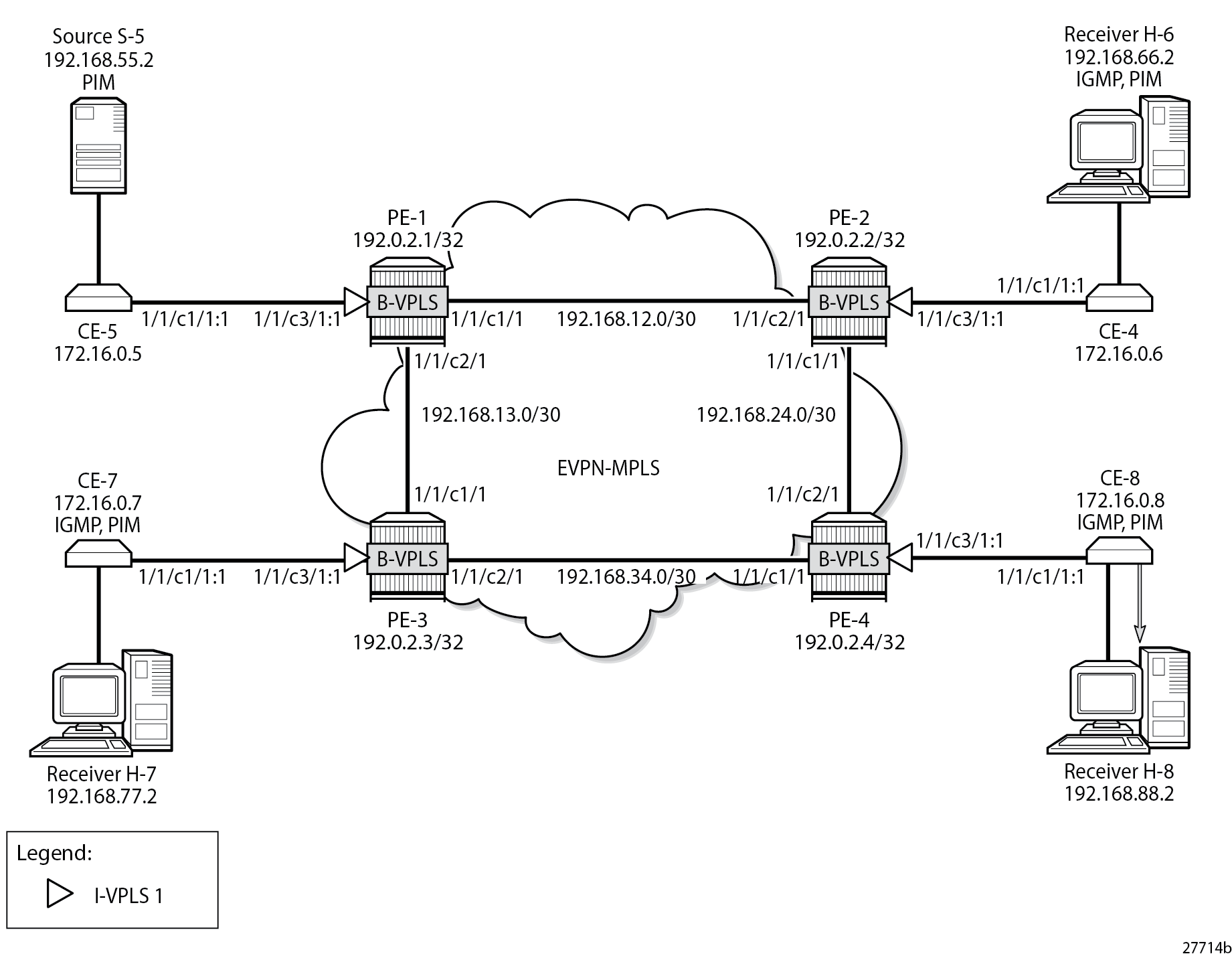
Example Topology for PBB-EVPN without MH shows the example topology with source S-5 and receivers H-6, H-7, and H-8 attached to CEs that are connected to PEs. On the PEs, B-VPLS 100 is configured and I-VPLS 1 is associated with it. B-VPLS 100 has EVPN-MPLS enabled. An mLDP P2MP provider tunnel is used to distribute multicast traffic from PE-1 to the other PEs.
The initial configuration includes:
Cards, MDAs, ports
Router interfaces
IS-IS enabled on the PEs (alternatively, OSPF can be used)
LDP enabled on the PEs
BGP is configured on the PEs with address family EVPN, and PE-2 is configured as route reflector (RR). The BGP configuration on PE-2 is as follows:
On PE-2:
configure
    router "Base"
        bgp
            rapid-withdrawal
            rapid-update evpn
            group INTERNAL
                family evpn
                type internal
                cluster 192.0.2.2
                neighbor 192.0.2.1
                exit
                neighbor 192.0.2.3
                exit
                neighbor 192.0.2.4
                exit
            exit
        exit all
PBB-EVPN without MH – No PIM Snooping
B-VPLS 100 is configured with EVPN-MPLS enabled on all PEs. Multicast LDP is configured in B-VPLS 100 with PE-1 as the P2MP tunnel root node (root-and-leaf) and the other PEs as leaf nodes (no root-and-leaf is default). An (optional) ISID policy defines that the default multicast tree -which is used by the P2MP mLDP tunnel- is used for ISIDs 1 and 2 (range 1 to 2). The configuration of B-VPLS 100 on PE-1 is as follows:
On PE-1:
configure
    service
        vpls 100 name "B-VPLS 100" customer 1 b-vpls create
            description "B-VPLS 100"
            service-mtu 2000
            pbb
                source-bmac 00:00:00:00:00:01
            exit
            split-horizon-group "CORE" create
            exit
            bgp
            exit
            bgp-evpn
                evi 100
                mpls
                    split-horizon-group "CORE"
                    ingress-replication-bum-label
                    auto-bind-tunnel
                        resolution any
                    exit
                    no shutdown
                exit
            exit
            provider-tunnel
                inclusive
                    owner bgp-evpn-mpls
                    root-and-leaf
                    mldp
                    no shutdown
                exit
            exit
            isid-policy
                entry 1 create
                    use-def-mcast
                    no advertise-local
                    range 1 to 2
                exit
            exit
            no shutdown
        exit all
The configuration of B-VPLS on the other PEs is similar, but without the root-and-leaf option.
In B-VPLS 100 on root node PE-1, the following mLDP provider tunnel is created with Provider Multicast Service Interface (PMSI) owner bgpEvpnMpls. PE-1 is configured as root-and-leaf node.
*A:PE-1# show service id 100 provider-tunnel

===============================================================================
Service Provider Tunnel Information
===============================================================================
Type               : inclusive          Root and Leaf      : enabled
Admin State        : enabled            Data Delay Intvl   : 15 secs
PMSI Type          : ldp                LSP Template       :
Remain Delay Intvl : 0 secs             LSP Name used      : 8193
PMSI Owner         : bgpEvpnMpls
Oper State         : up                 Root Bind Id       : 32767
-------------------------------------------------------------------------------
Type               : selective          Wildcard SPMSI     : disabled
Admin State        : disabled           Data Delay Intvl   : 3 secs
PMSI Type          : none               Max P2MP SPMSI     : 10
PMSI Owner         : none
===============================================================================
When the B-VPLS is created, I-VPLS 1 can be associated with it, as follows:
On PE-1:
configure
    service
        vpls 1 name "I-VPLS 1" customer 1 i-vpls create
            pbb
                backbone-vpls 100
                exit
            exit
            sap 1/1/c3/1:1 create
            exit
            no shutdown
        exit all
The configuration of I-VPLS 1 on the other PEs is identical.
CE-6, CE-7, and CE-8 have IGMP enabled on the interface toward the receiver and PIM enabled on all interfaces. Source-specific multicast is used in this example. The configuration on CE-8 is as follows:
On CE-8:
configure
    router "Base"
        interface "int-CE-8-H-8"
            address 192.168.88.1/24
            port 1/1/c2/1
        exit
        interface "int-CE-8-PE-4"
            address 172.16.0.8/16
            port 1/1/c1/1:1
        exit
        interface "system"
            address 192.0.2.8/32
        exit
        static-route-entry 192.168.55.0/30
            next-hop 172.16.0.5
                no shutdown
            exit
        exit
        igmp
            interface int-CE-8-H-8
            exit
        exit
        pim
            apply-to all
        exit
    exit all
The static route is required on the receiving CEs for the PIM join/prune messages to reach the multicast source S-5 with IP address 192.168.55.2; only IP subnet 172.16.0.0/16 can be reached via the VPLS.
CE-5 has PIM enabled and static routes configured to reach the receiving hosts, as follows:
On CE-5:
configure
router "Base"
interface "int-CE-5-PE-1"
address 172.16.0.5/16
port 1/1/c1/1:1
exit
interface "int-CE-5-S-5"
address 192.168.55.1/30
port 1/1/c3/1
exit
interface "system"
address 192.0.2.5/32
exit
static-route-entry 192.168.66.0/24
next-hop 172.16.0.6
no shutdown
exit
exit
static-route-entry 192.168.77.0/24
next-hop 172.16.0.7
no shutdown
exit
exit
static-route-entry 192.168.88.0/24
next-hop 172.16.0.8
no shutdown
exit
exit
pim
apply-to all
exit
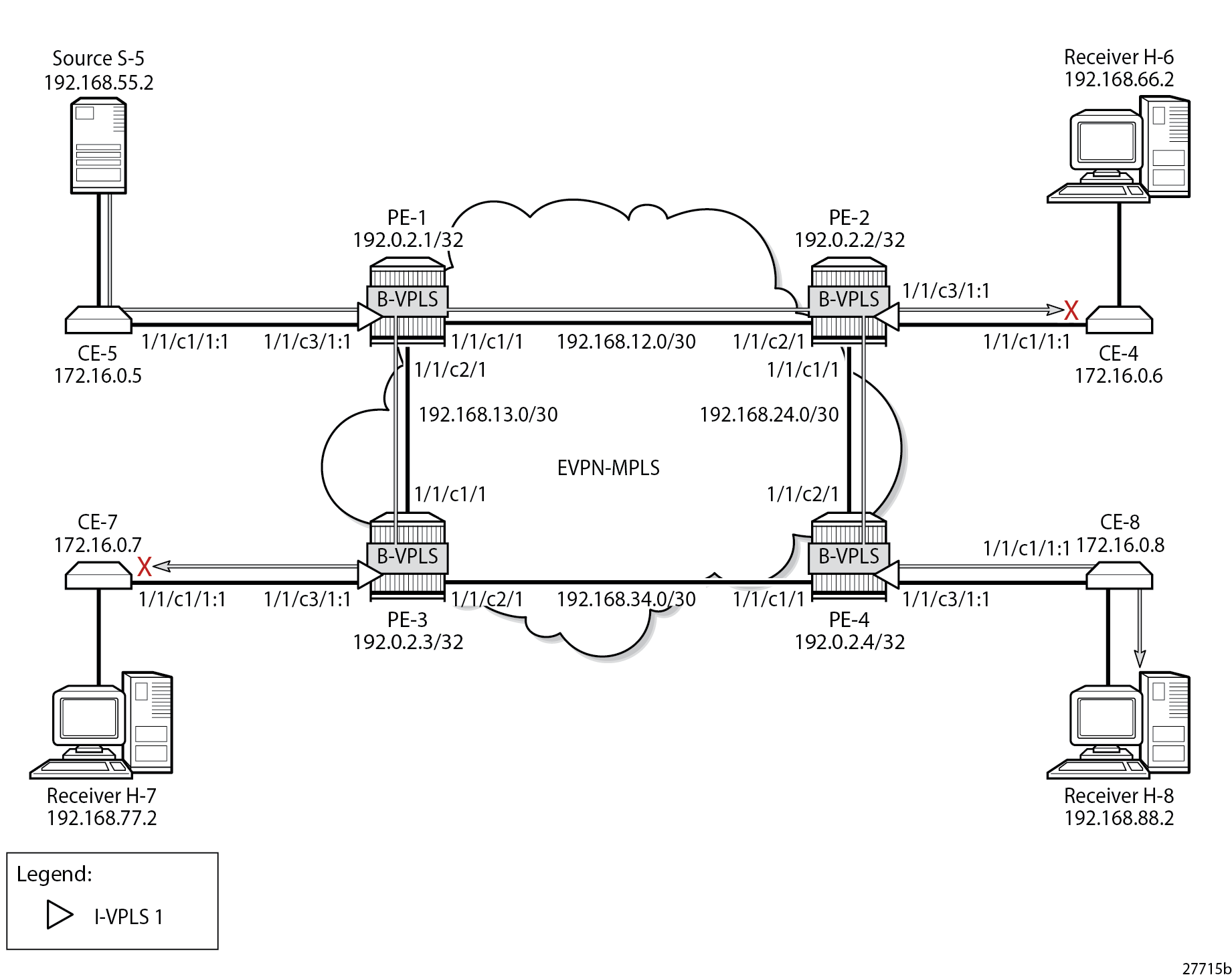
exit allWhen receiver H-8 sends an IGMP report to join multicast group (S,G), CE-8 sends a PIM join message to CE-5. This PIM join message is flooded by the PEs. When CE-5 receives the PIM join message, it forwards the multicast stream to receiver H-8. PIM snooping is disabled by default and the MFIB on each of the PEs remains empty, so the multicast stream is not only sent to CE-8, but also to CE-6 and CE-7. CE-6 and CE-7 drop this stream when no receiver is active, while CE-8 forwards the multicast stream to receiver H-8, as shown in Multicast Stream to Receiver H-8 with PIM Snooping Disabled.
PBB-EVPN without MH – PIM Snooping for IPv4 Enabled
PIM snooping for IPv4 is enabled in I-VPLS 1 on all PEs as follows:
On all PEs:
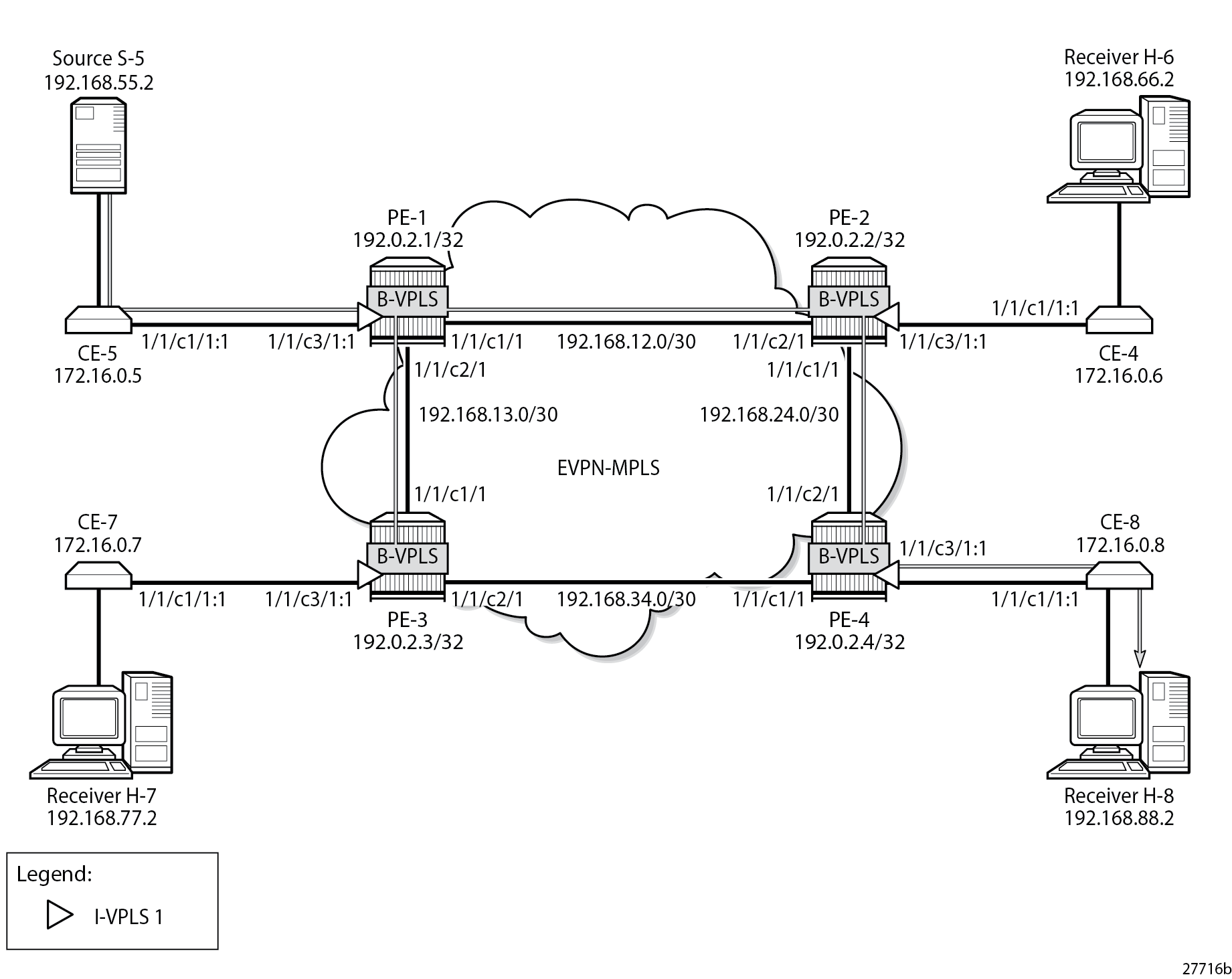
configure service vpls 1 pim-snoopingWhen PIM snooping for IPv4 is enabled, the PEs only forward the multicast traffic to those CEs that have sent PIM join messages for that multicast group. This implies that PE-2 and PE-3 do not forward traffic to the CEs; only PE-4 forwards traffic toward CE-8 and CE-8 forwards to receiver H-8, as shown in Multicast Stream to Receiver H-8 with PIM Snooping Enabled.
When PIM snooping for IPv4 is enabled, PE-1 has the following two PIM snooping ports: the SAP toward the source and the backbone b-EVPN-MPLS interface, which is treated as one entity for all PBB-EVPN destinations.
*A:PE-1# show service id 1 pim-snooping port

===============================================================================
PIM Snooping Port ipv4
===============================================================================
Port Id                                                         Opr   PW Fwding
-------------------------------------------------------------------------------
SAP:1/1/c3/1:1                                                  Up    Actv
b-EVPN-MPLS                                                     Up    Actv
===============================================================================
PE-1 has the following PIM snooping neighbors: CE-5 with IP address 172.16.0.5 is attached via SAP 1/1/c3/1:1, and the other CEs are attached to the b-EVPN-MPLS. Even though this b-EVPN-MPLS is treated as one entity, individual entries are shown for each B-VPLS PBB-EVPN destination, as follows:
*A:PE-1# show service id 1 pim-snooping neighbor

===============================================================================
PIM Snooping Neighbors ipv4
===============================================================================
Port Id                 Nbr DR Prty     Up Time       Expiry Time     Hold Time
  Nbr Address
-------------------------------------------------------------------------------
SAP:1/1/c3/1:1          1               0d 00:01:21   0d 00:01:24     105
  172.16.0.5
b-EVPN-MPLS             1               0d 00:01:30   0d 00:01:45     105
  172.16.0.6
b-EVPN-MPLS             1               0d 00:01:18   0d 00:01:27     105
  172.16.0.7
b-EVPN-MPLS             1               0d 00:01:34   0d 00:01:41     105
  172.16.0.8
-------------------------------------------------------------------------------
Neighbors : 4
===============================================================================
Receiver H-8 joins the multicast stream and the PIM group with group address 232.1.1.1, and source address 192.168.55.2 is shown on CE-8 with incoming interface toward PE-4 and outgoing interface toward H-8. The Reverse Path Forwarding (RPF) neighbor is CE-5 with IP address 172.16.0.5, as follows:
*A:CE-8# show router pim group detail

===============================================================================
PIM Source Group ipv4
===============================================================================
Group Address      : 232.1.1.1
Source Address     : 192.168.55.2
RP Address         : 0
Advt Router        :
Flags              :                    Type               : (S,G)
Mode               : sparse
MRIB Next Hop      : 172.16.0.5
MRIB Src Flags     : remote
Keepalive Timer    : Not Running
Up Time            : 0d 00:08:19        Resolved By        : rtable-u

Up JP State        : Joined             Up JP Expiry       : 0d 00:00:41
Up JP Rpt          : Not Joined StarG   Up JP Rpt Override : 0d 00:00:00

Register State     : No Info
Reg From Anycast RP: No

Rpf Neighbor       : 172.16.0.5
Incoming Intf      : int-CE-8-PE-4
Outgoing Intf List : int-CE-8-H-8

Curr Fwding Rate   : 9751.560 kbps
Forwarded Packets  : 75064              Discarded Packets  : 0
Forwarded Octets   : 111244848          RPF Mismatches     : 0
Spt threshold      : 0 kbps             ECMP opt threshold : 7
Admin bandwidth    : 1 kbps
-------------------------------------------------------------------------------
Groups : 1
===============================================================================
With PIM snooping for IPv4 enabled, and after receiving a PIM join message for multicast (192.168.55.2, 232.1.1.1), the MFIB on PE-1 has an entry for group address 232.1.1.1 and source address 192.168.55.2, as follows. The local SAP connects to CE-5; the other port IDs correspond to the b-EVPN-MPLS interface.
*A:PE-1# show service id 1 mfib

===============================================================================
Multicast FIB, Service 1
===============================================================================
Source Address  Group Address         Port Id                      Svc Id   Fwd
                                                                            Blk
-------------------------------------------------------------------------------
192.168.55.2    232.1.1.1             sap:1/1/c3/1:1               Local    Fwd
                                      b-mpls:192.0.2.2:524282      100      Fwd
                                      b-mpls:192.0.2.3:524282      100      Fwd
                                      b-mpls:192.0.2.4:524282      100      Fwd
-------------------------------------------------------------------------------
Number of entries: 1
===============================================================================
The MFIB on PE-4 is similar, with a local SAP connecting to CE-8 and three b-eMpls port IDs for each of the PE peers. In contrast, the MFIBs on PE-2 and PE-3 are empty, because no multicast traffic needs to be forwarded to the attached CEs, as follows:
*A:PE-2# show service id 1 mfib

===============================================================================
Multicast FIB, Service 1
===============================================================================
Source Address  Group Address         Port Id                      Svc Id   Fwd
                                                                            Blk
-------------------------------------------------------------------------------
-------------------------------------------------------------------------------
Number of entries: 0
===============================================================================
The following MFIB statistics on PE-1 show the number of matched packets and matched octets for group address 232.1.1.1 and source address 192.168.55.2:
*A:PE-1# show service id 1 mfib statistics

===============================================================================
Multicast FIB Statistics, Service 1
===============================================================================
Source Address  Group Address       Matched Pkts          Matched Octets
                                                          Forwarding Rate
-------------------------------------------------------------------------------
192.168.55.2    232.1.1.1           60968                 91452000
                                                          398.559 kbps
-------------------------------------------------------------------------------
Number of entries: 1
===============================================================================
The following shows that PE-2 receives the multicast packets on port 1/1/c2/1 and forwards them to PE-4 on port 1/1/c1/1. With PIM snooping for IPv4 enabled, PE-2 does not forward the traffic to CE-6 on port 1/1/c3/1 because no PIM join message was received from CE-6. Besides the multicast traffic, some signaling messages (such as PIM, IS-IS, and so on) are sent on the ports, which explains why all counters have non-zero values.
*A:PE-2# show port 1/1/c1/1 statistics

===============================================================================
Port Statistics on Slot 1
===============================================================================
Port                        Ingress Packets                  Ingress Octets
Id                           Egress Packets                   Egress Octets
-------------------------------------------------------------------------------
1/1/c1/1                                 18                            1796
                                      16474                        25275378
===============================================================================

*A:PE-2# show port 1/1/c2/1 statistics

===============================================================================
Port Statistics on Slot 1
===============================================================================
Port                        Ingress Packets                  Ingress Octets
Id                           Egress Packets                   Egress Octets
-------------------------------------------------------------------------------
1/1/c2/1                              16477                        25275662
                                         23                            2299
===============================================================================

*A:PE-2# show port 1/1/c3/1 statistics

===============================================================================
Port Statistics on Slot 1
===============================================================================
Port                        Ingress Packets                  Ingress Octets
Id                           Egress Packets                   Egress Octets
-------------------------------------------------------------------------------
1/1/c3/1                                  1                              76
                                          2                             152
===============================================================================
The following PIM snooping group with group address 232.1.1.1 and source address 192.168.55.2 is shown on PE-1. The incoming interface is the SAP toward CE-5 and the outgoing interface is the b-EVPN-MPLS interface. A single b-EVPN-MPLS interface is shown in the outgoing interface list, regardless of the B-VPLS PBB-EVPN destination. The split-horizon mechanism ensures that all traffic from the incoming interface SAP 1/1/c3/1:1 is only forwarded on the b-EVPN-MPLS interface, not sent back on the SAP.
*A:PE-1# show service id 1 pim-snooping group detail

===============================================================================
PIM Snooping Source Group ipv4
===============================================================================
Group Address      : 232.1.1.1
Source Address     : 192.168.55.2
Up Time            : 0d 00:01:14

Up JP State        : Joined             Up JP Expiry       : 0d 00:00:46
Up JP Rpt          : Not Joined StarG   Up JP Rpt Override : 0d 00:00:00

RPF Neighbor       : 172.16.0.5
Incoming Intf      : SAP:1/1/c3/1:1
Outgoing Intf List : b-EVPN-MPLS, SAP:1/1/c3/1:1

Forwarded Packets  : 60968              Forwarded Octets   : 91452000
-------------------------------------------------------------------------------
Groups : 1
===============================================================================
On PE-2 and PE-3, there are no PIM snooping groups.
On PE-4, the PIM snooping group with group address 232.1.1.1 and source address 192.168.55.2 has the b-EVPN-MPLS interface as incoming interface and SAP 1/1/c3/1:1 toward CE-8 as outgoing interface, as follows. The split-horizon mechanism ensures that traffic received from the b-EVPN-MPLS interface is not forwarded on the b-EVPN-MPLS interface to the other PEs, so it is only forwarded on the SAP 1/1/c3/1:1 toward CE-8.
*A:PE-4# show service id 1 pim-snooping group 232.1.1.1 detail

===============================================================================
PIM Snooping Source Group ipv4
===============================================================================
Group Address      : 232.1.1.1
Source Address     : 192.168.55.2
Up Time            : 0d 00:01:21

Up JP State        : Joined             Up JP Expiry       : 0d 00:00:38
Up JP Rpt          : Not Joined StarG   Up JP Rpt Override : 0d 00:00:00

RPF Neighbor       : 172.16.0.5
Incoming Intf      : b-EVPN-MPLS
Outgoing Intf List : b-EVPN-MPLS, SAP:1/1/c3/1:1

Forwarded Packets  : 66623              Forwarded Octets   : 100867222
-------------------------------------------------------------------------------
Groups : 1
===============================================================================
PBB-EVPN with MH – No PIM Snooping
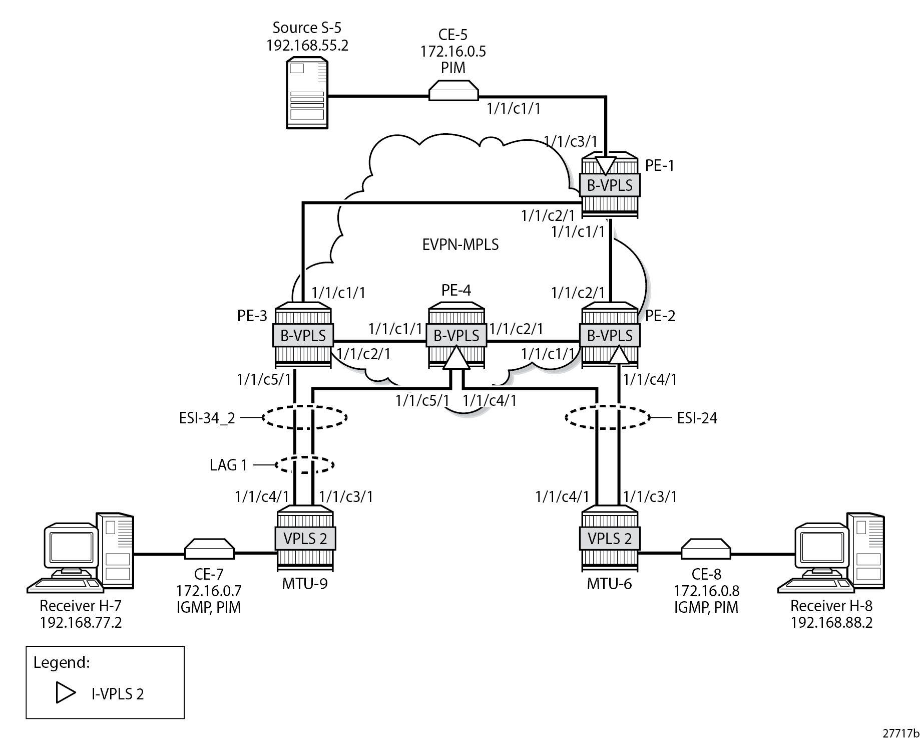
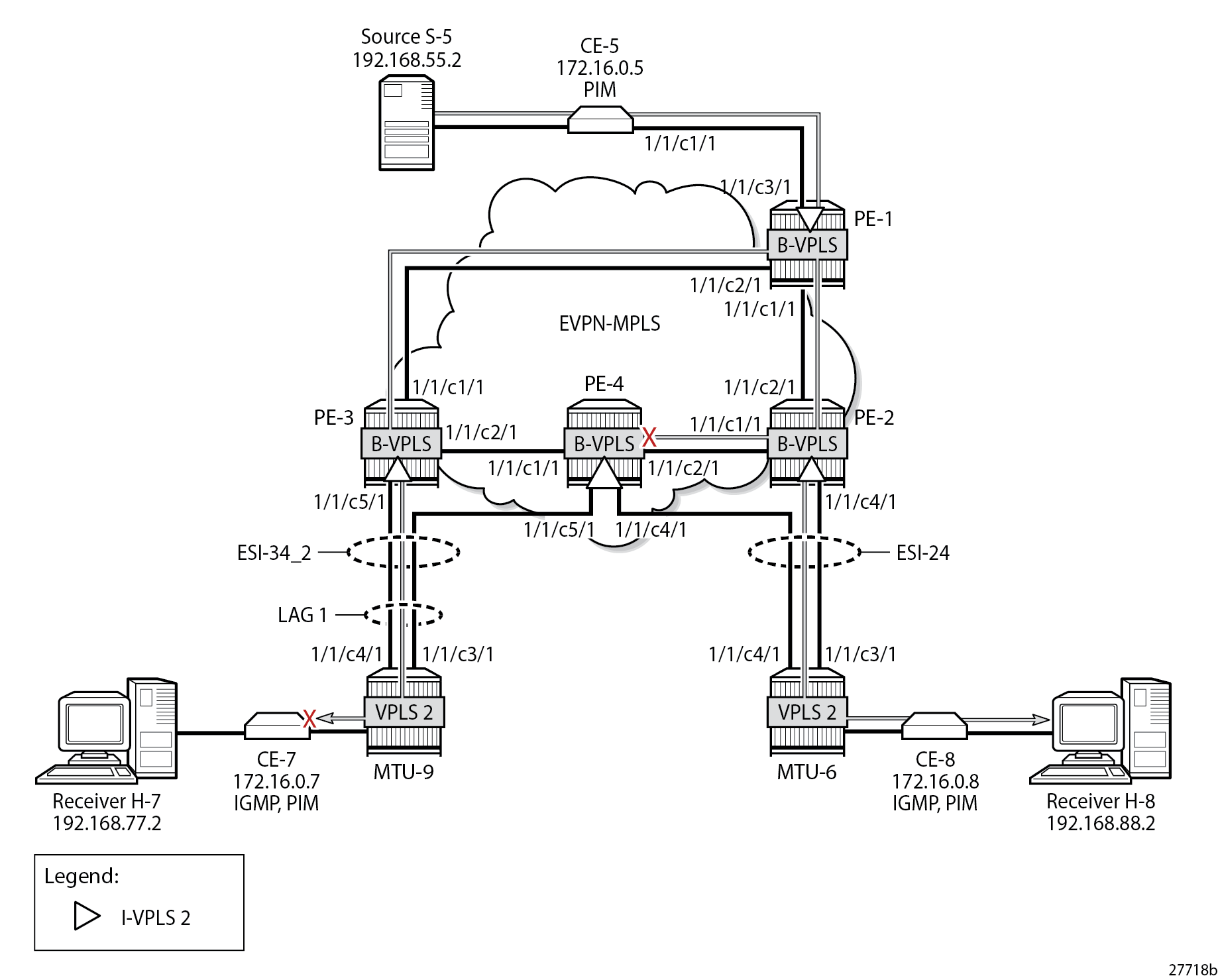
Example Topology for PBB-EVPN with MH shows the example topology with CE-7 attached to MTU-9, which is connected to both PE-3 and PE-4 via LAG 1. Virtual ES (vES) ESI-34_2 is configured in all-active MH mode using LAG 1 for dot1q value 2. MTU-6 is connected to PE-2 and PE-4 with SDPs. These SDPs are associated with a single-active MH ES ESI-24.
The configuration of I-VPLS 2 is similar to the preceding configuration of I-VPLS 1 on all PEs.
On PE-2, PE-3, and PE-4, one or more ESs are configured. The service configuration on PE-2 is as follows. An SDP is configured toward MTU-6 that is associated with a single-active MH ES ESI-24, that is non-restrictive -after failover, it does not restore to the initial designated forwarder (DF) if available again; see chapter Preference-based and Non-revertive EVPN DF Election. The manually configured preference is 200 on PE-2, which is higher than preference 50 at PE-3, so PE-2 is the DF when no failover has occurred. Spoke-SDP 26:2 is associated with I-VPLS 2. The B-VPLS 100 remains unchanged and is not repeated here.
On PE-2:
configure
    service
        sdp 26 mpls create
            far-end 192.0.2.6
            ldp
            no shutdown
        exit
        system
            bgp-evpn
                ethernet-segment "ESI-24" create
                    esi 01:00:00:00:00:24:00:00:00:01
                    source-bmac-lsb 24-02 es-bmac-table-size 8
                    es-activation-timer 3
                    service-carving
                        mode manual
                        manual
                            preference non-revertive create
                                value 200
                            exit
                        exit
                    exit
                    multi-homing single-active
                    sdp 26
                    no shutdown
                exit
            exit
        exit
        vpls 2 name "I-VPLS 2" customer 1 i-vpls create
            pbb
                backbone-vpls 100
                exit
            exit
            spoke-sdp 26:2 create
            exit
            no shutdown
        exit
    exit all
On PE-4, LAG 1 is configured in access mode with dot1q encapsulation on the port to MTU-9, as follows. The LAG configuration is similar on PE-3.
On PE-4:
configure
    lag 1
        mode access
        encap-type dot1q
        port 1/1/c5/1
        lacp active administrative-key 1 system-id 00:00:00:00:01:34
        no shutdown
    exit all
Single-active ES ESI-24 is configured on PE-4, together with a virtual ES ESI-34_2, which is an all-active MH virtual ES that applies to LAG 1 for I-VPLS 2 only (q-tag-range 2); see chapter Virtual Ethernet Segments. The preference for the DF election is configured manually to a value of 50 (which is lower than preference 200 on the remote peer in the ES). I-VPLS 2 has a SAP and a spoke-SDP configured. The service configuration on PE-4 is as follows:
On PE-4:
configure
    service
        sdp 46 mpls create
            far-end 192.0.2.6
            ldp
            no shutdown
        exit
        system
            bgp-evpn
                ethernet-segment "ESI-24" create
                    esi 01:00:00:00:00:24:00:00:00:01
                    source-bmac-lsb 24-04 es-bmac-table-size 8
                    es-activation-timer 3
                    service-carving
                        mode manual
                        manual
                            preference non-revertive create
                                value 50
                            exit
                        exit
                    exit
                    multi-homing single-active
                    sdp 46
                    no shutdown
                exit
                ethernet-segment "ESI-34_2" virtual create
                    esi 01:00:00:00:00:34:02:00:00:01
                    source-bmac-lsb 34-34 es-bmac-table-size 8
                    es-activation-timer 3
                    service-carving
                        mode manual
                        manual
                            preference non-revertive create
                                value 50
                            exit
                        exit
                    exit
                    multi-homing all-active
                    lag 1
                    dot1q
                        q-tag-range 2
                    exit
                    no shutdown
                exit
            exit
        exit
        vpls 2 name "I-VPLS 2" customer 1 i-vpls create
            pbb
                backbone-vpls 100
                exit
            exit
            sap lag-1:2 create
            exit
            spoke-sdp 46:2 create
            exit
            no shutdown
        exit
        vpls 100 name "B-VPLS 100" customer 1 b-vpls create
            pbb
                use-es-bmac
            exit
        exit
    exit all
On PE-4, the source BMAC in the all-active MH ESI-34_2 is identical to the source BMAC on remote peer PE-3, but in the single-active MH ESI-24, the source BMAC must be different. Remote PEs might send traffic to the NDF PE based on the shared source BMAC, which is fine for all-active MH ESs, but not for single-active MH ESs.
The following service configuration on PE-3 includes an all-active virtual ES ESI-34_2 with preference 200, which makes PE-3 the DF for ESI-34_2 when no failover has occurred. After failover, PE-4 becomes DF, and it does not revert to PE-3 when available.
On PE-3:
configure
    service
        system
            bgp-evpn
                ethernet-segment "ESI-34_2" virtual create
                    esi 01:00:00:00:00:34:02:00:00:01
                    source-bmac-lsb 34-34 es-bmac-table-size 8
                    es-activation-timer 3
                    service-carving
                        mode manual
                        manual
                            preference non-revertive create
                                value 200
                            exit
                        exit
                    exit
                    multi-homing all-active
                    lag 1
                    dot1q
                        q-tag-range 2
                    exit
                    no shutdown
                exit
            exit
        exit
        vpls 2 name "I-VPLS 2" customer 1 i-vpls create
            pbb
                backbone-vpls 100
                exit
            exit
            sap lag-1:2 create
            exit
            no shutdown
        exit
        vpls 100 name "B-VPLS 100" customer 1 b-vpls create
            pbb
                use-es-bmac
            exit
        exit
    exit all
The following is the service configuration on MTU-6:
On MTU-6:
configure
    service
        sdp 62 mpls create
            far-end 192.0.2.2
            ldp
            no shutdown
        exit
        sdp 64 mpls create
            far-end 192.0.2.4
            ldp
            no shutdown
        exit
        vpls 2 name "VPLS 2" customer 1 create
            endpoint "x" create
            exit
            sap 1/2/c1/1:2 create
            exit
            spoke-sdp 62:2 endpoint "x" create
            exit
            spoke-sdp 64:2 endpoint "x" create
            exit
            no shutdown
        exit
    exit all
The following is the LAG configuration on MTU-9:
On MTU-9:
configure
    lag 1
        mode access
        encap-type dot1q
        port 1/1/c3/1
        port 1/1/c4/1
        lacp active administrative-key 32768
        no shutdown
    exit all
The configuration of VPLS 2 on MTU-9 is as follows:
On MTU-9:
configure
    service
        vpls 2 name "VPLS 2" customer 1 create
            sap lag-1:2 create
            exit
            sap 1/1/c1/1:2 create
            exit
            no shutdown
        exit all
For I-VPLS 2, PE-2 is the DF in ES ESI-24, as follows:
*A:PE-2# show service id 2 ethernet-segment
No sap entries

===============================================================================
SDP Ethernet-Segment Information
===============================================================================
SDP                   Eth-Seg                          Status
-------------------------------------------------------------------------------
26:2                  ESI-24                           DF
===============================================================================
No vxlan instance entries
PE-3 is the DF in virtual ES ESI-34_2, as follows:
*A:PE-3# show service id 2 ethernet-segment

===============================================================================
SAP Ethernet-Segment Information
===============================================================================
SAP                   Eth-Seg                          Status
-------------------------------------------------------------------------------
lag-1:2               ESI-34_2                         DF
===============================================================================
No sdp entries
No vxlan instance entries
PE-4 is the Non-DF (NDF) for both ESI-24 and ESI-34_2, as follows:
*A:PE-4# show service id 2 ethernet-segment

===============================================================================
SAP Ethernet-Segment Information
===============================================================================
SAP                   Eth-Seg                          Status
-------------------------------------------------------------------------------
lag-1:2               ESI-34_2                         NDF
===============================================================================

===============================================================================
SDP Ethernet-Segment Information
===============================================================================
SDP                   Eth-Seg                          Status
-------------------------------------------------------------------------------
46:2                  ESI-24                           NDF
===============================================================================
No vxlan instance entries
When H-8 sends an IGMP report to join multicast group 232.1.1.1 from source 192.168.55.2, CE-5 forwards the multicast stream after receiving the corresponding PIM join message. PE-1 forwards the multicast traffic on the P2MP mLDP tunnel to all EVPN-MPLS destinations: PE-2, PE-3, and PE-4. PE-2 is the DF for ESI-24 and forwards the traffic to MTU-6, which forwards it to CE-8, where it is sent to the attached receiver H-8 that joined the multicast group. PE-3 is the DF for ESI-34_2 and sends the multicast stream to MTU-9, which forwards it to CE-7, where it is dropped because no attached receiver has joined the multicast group. PE-4 is the NDF for both ESs, so it does not forward the traffic to MTU-6 or MTU-9. EVPN-MPLS with MH - PIM Snooping Disabled – Receiver H-8 Joined shows how this multicast is forwarded when PIM snooping is disabled.
PBB-EVPN with MH – PIM Snooping for IPv4 Enabled
PIM snooping for IPv4 is enabled in I-VPLS 2 on all PEs with the following command:
On all PEs:
configure service vpls 2 pim-snooping
All PEs have three PIM snooping neighbors: CE-5, CE-7, and CE-8. The list of PIM snooping neighbors on PE-1 is as follows:
*A:PE-1# show service id 2 pim-snooping neighbor

===============================================================================
PIM Snooping Neighbors ipv4
===============================================================================
Port Id                 Nbr DR Prty     Up Time       Expiry Time     Hold Time
  Nbr Address
-------------------------------------------------------------------------------
SAP:1/1/c3/1:2          1               0d 00:00:59   0d 00:01:16     105
  172.16.0.5
b-EVPN-MPLS             1               0d 00:00:42   0d 00:01:33     105
  172.16.0.7
b-EVPN-MPLS             1               0d 00:01:08   0d 00:01:37     105
  172.16.0.8
-------------------------------------------------------------------------------
Neighbors : 3
===============================================================================
When H-7 and H-8 join the group 232.1.1.1 via source 192.168.55.2, the PIM join messages are snooped by the PEs and the MFIB is built. The MFIB on PE-1 contains one entry for group address 232.1.1.1 and source address 192.168.55.2 with four port IDs: the local SAP to CE-5 and the B-VPLS PBB-EVPN destinations, as follows:
*A:PE-1# show service id 2 mfib

===============================================================================
Multicast FIB, Service 2
===============================================================================
Source Address  Group Address         Port Id                      Svc Id   Fwd
                                                                            Blk
-------------------------------------------------------------------------------
192.168.55.2    232.1.1.1             sap:1/1/c3/1:2               Local    Fwd
                                      b-mpls:192.0.2.2:524282      100      Fwd
                                      b-mpls:192.0.2.3:524282      100      Fwd
                                      b-mpls:192.0.2.4:524282      100      Fwd
-------------------------------------------------------------------------------
Number of entries: 1
===============================================================================
In a similar way, the other PEs that snooped PIM messages build their MFIBs. On PE-2, the following MFIB is shown when H-8 has joined the multicast group.
*A:PE-2# show service id 2 mfib

===============================================================================
Multicast FIB, Service 2
===============================================================================
Source Address  Group Address         Port Id                      Svc Id   Fwd
                                                                            Blk
-------------------------------------------------------------------------------
192.168.55.2    232.1.1.1             sdp:26:2                     Local    Fwd
                                      b-mpls:192.0.2.1:524282      100      Fwd
                                      b-mpls:192.0.2.3:524282      100      Fwd
                                      b-mpls:192.0.2.4:524282      100      Fwd
-------------------------------------------------------------------------------
Number of entries: 1
===============================================================================
On PE-3, the following MFIB is present when H-7 has joined the multicast group:
*A:PE-3# show service id 2 mfib

===============================================================================
Multicast FIB, Service 2
===============================================================================
Source Address  Group Address         Port Id                      Svc Id   Fwd
                                                                            Blk
-------------------------------------------------------------------------------
192.168.55.2    232.1.1.1             sap:lag-1:2                  Local    Fwd
                                      b-mpls:192.0.2.1:524282      100      Fwd
                                      b-mpls:192.0.2.2:524282      100      Fwd
                                      b-mpls:192.0.2.4:524282      100      Fwd
-------------------------------------------------------------------------------
Number of entries: 1
===============================================================================
Furthermore, data-driven PIM state synchronization between PEs in an all-active MH ES allows the NDF PE-4 to build its MFIB, even when the NDF does not forward multicast traffic to the receivers. When the NDF has the MFIB information, the failover is faster and the loss of traffic is limited. For data-driven PIM state synchronization, the source BMAC must be identical within the ES, so it only works for all-active MH in PBB-EVPN, not for single-active MH. The MFIB on PE-4 contains the SAP from the all-active MH ESI-34_2, but not the spoke-SDP from the single-active MH ESI-24, as follows:
*A:PE-4# show service id 2 mfib

===============================================================================
Multicast FIB, Service 2
===============================================================================
Source Address  Group Address         Port Id                      Svc Id   Fwd
                                                                            Blk
-------------------------------------------------------------------------------
192.168.55.2    232.1.1.1             sap:lag-1:2                  Local    Fwd
                                      b-mpls:192.0.2.1:524282      100      Fwd
                                      b-mpls:192.0.2.2:524282      100      Fwd
                                      b-mpls:192.0.2.3:524282      100      Fwd
-------------------------------------------------------------------------------
Number of entries: 1
===============================================================================
The snooped PIM group information on PE-1 shows the SAP to CE-5 as incoming interface and the b-EVPN-MPLS interface as outgoing, as follows. The split-horizon mechanism prevents multicast traffic coming from the SAP to CE-5 from being returned.
*A:PE-1# show service id 2 pim-snooping group detail

===============================================================================
PIM Snooping Source Group ipv4
===============================================================================
Group Address      : 232.1.1.1
Source Address     : 192.168.55.2
Up Time            : 0d 00:02:19

Up JP State        : Joined             Up JP Expiry       : 0d 00:00:41
Up JP Rpt          : Not Joined StarG   Up JP Rpt Override : 0d 00:00:00

RPF Neighbor       : 172.16.0.5
Incoming Intf      : SAP:1/1/c3/1:2
Outgoing Intf List : b-EVPN-MPLS, SAP:1/1/c3/1:2

Forwarded Packets  : 114411             Forwarded Octets   : 171616500
-------------------------------------------------------------------------------
Groups : 1
===============================================================================
On PE-2, the incoming interface is the b-EVPN-MPLS interface and the outgoing interface is the spoke-SDP toward MTU-6, as follows:
*A:PE-2# show service id 2 pim-snooping group detail

===============================================================================
PIM Snooping Source Group ipv4
===============================================================================
Group Address      : 232.1.1.1
Source Address     : 192.168.55.2
Up Time            : 0d 00:00:49

Up JP State        : Joined             Up JP Expiry       : 0d 00:00:59
Up JP Rpt          : Not Joined StarG   Up JP Rpt Override : 0d 00:00:00

RPF Neighbor       : 172.16.0.5
Incoming Intf      : b-EVPN-MPLS
Outgoing Intf List : b-EVPN-MPLS, SPOKE_SDP:26:2

Forwarded Packets  : 40909              Forwarded Octets   : 61936226
-------------------------------------------------------------------------------
Groups : 1
===============================================================================
On PE-3, the incoming interface is the b-EVPN-MPLS interface and the outgoing interface is the SAP lag-1:2 toward MTU-9, as follows:
*A:PE-3# show service id 2 pim-snooping group detail

===============================================================================
PIM Snooping Source Group ipv4
===============================================================================
Group Address      : 232.1.1.1
Source Address     : 192.168.55.2
Up Time            : 0d 00:02:22

Up JP State        : Joined             Up JP Expiry       : 0d 00:00:30
Up JP Rpt          : Not Joined StarG   Up JP Rpt Override : 0d 00:00:00

RPF Neighbor       : 172.16.0.5
Incoming Intf      : b-EVPN-MPLS
Outgoing Intf List : b-EVPN-MPLS, SAP:lag-1:2

Forwarded Packets  : 117006             Forwarded Octets   : 177147084
-------------------------------------------------------------------------------
Groups : 1
===============================================================================
In case of all-active MH ES ESI-34_2, one of the PE -DF or NDF- in the ES forwards the PIM states to its remote peer and therefore, PE-4 has the same PIM snooping group information as PE-3, as follows:
*A:PE-4# show service id 2 pim-snooping group detail

===============================================================================
PIM Snooping Source Group ipv4
===============================================================================
Group Address      : 232.1.1.1
Source Address     : 192.168.55.2
Up Time            : 0d 00:02:23

Up JP State        : Joined             Up JP Expiry       : 0d 00:00:29
Up JP Rpt          : Not Joined StarG   Up JP Rpt Override : 0d 00:00:00

RPF Neighbor       : 172.16.0.5
Incoming Intf      : b-EVPN-MPLS
Outgoing Intf List : b-EVPN-MPLS, SAP:lag-1:2

Forwarded Packets  : 118048             Forwarded Octets   : 178724672
-------------------------------------------------------------------------------
Groups : 1
===============================================================================
With the PIM snooping group information available on the NDF, the traffic loss is limited when the NDF PE-4 becomes the DF after failover. Data-driven PIM state synchronization does not store PIM states in a database, so the DF election in the ES should be configured as non-revertive, to prevent that when the preferred DF is restored after a failover, the system would revert to a DF that is unaware of the PIM state.
PE-4 is also NDF in the single-active MH ES ESI-24, but it received no PIM state synchronization information from DF PE-2. Data-driven PIM state synchronization is not supported for single-active MH in PBB-EVPN services, because it is not allowed to have two PEs in a single-active MH ES using the same source BMAC, with the potential risk of traffic sent by remote PEs to the NDF PE (based on it sending to the shared source BMAC) being dropped. However, for a faster failover in single-active MH, multi-chassis synchronization (MCS) can be configured, as described in the next section.
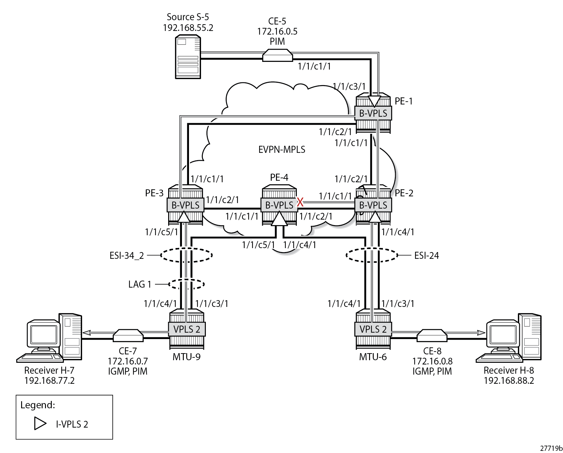
EVPN-MPLS with MH and PIM Snooping – Receivers H-7 and H-8 Joined shows the multicast traffic flow when PIM snooping is enabled and both receivers H-7 and H-8 have joined the multicast group. All PEs receive the multicast traffic on the P2MP tunnel, but only DF PE-2 and DF PE-3 forward the multicast traffic to the MTUs, which forward the traffic to the CEs, where it is forwarded to the receivers.
PBB-EVPN with MH – PIM Snooping for IPv4 with MCS
MCS of the IPv4 PIM snooping state for SAPs and spoke-SDPs can optionally be configured in the case of MH. MCS reduces the failover time when data-driven PIM state synchronization is not supported; for example, for single-active MH in PBB-EVPN services. The synchronization information is stored in an MCS synchronization DB. MCS is configured on PE-2, identifying the peer (PE-4), with PIM snooping for spoke-SDPs as MCS client application and the list of spoke-SDPs, as follows:
On PE-2:
configure
    redundancy
        multi-chassis
            peer 192.0.2.4 create
                sync
                    pim-snooping spoke-sdps
                    sdp 26 create
                        range 2-2 sync-tag "syncSA"
                    exit
                    no shutdown
                exit
                no shutdown
            exit all
On PE-4, MCS is configured for peer PE-2, as follows:
On PE-4:
configure
    redundancy
        multi-chassis
            peer 192.0.2.2 create
                sync
                    pim-snooping spoke-sdps
                    sdp 46 create
                        range 2-2 sync-tag "syncSA"
                    exit
                    no shutdown
                exit
                no shutdown
            exit all
When H-8 has joined the multicast group, the MCS sync-database on PE-2 shows the PIM snooping entries on the spoke-SDP 26:2 of the single-active MH ESI-24, as follows:
*A:PE-2# tools dump redundancy multi-chassis sync-database detail

If no entries are present for an application, no detail will be displayed.

FLAGS LEGEND: ld - local delete; da - delete alarm; pd - pending global delete;
              oal - omcr alarmed; ost - omcr standby

Peer Ip 192.0.2.4


Application pim-snooping-sdp
Sdp-id             Client Key
 SyncTag                          DLen  Flags            timeStamp
  deleteReason code and description                   #ShRec
-------------------------------------------------------------------------------
26:2               Adj 172.16.0.8
 syncSA                           72    -- -- -- --- --- 08/24/2023 14:26:36
  0x0                                                 0
26:2               IfSG SG 192.168.55.2 232.1.1.1
 syncSA                           69    -- -- -- --- --- 08/24/2023 14:26:26
  0x0                                                 0

The following totals are for:
 peer ip ALL, port/lag/sdp ALL, sync-tag ALL, application ALL
Valid Entries:                   2
Locally Deleted Entries:         0
Locally Deleted Alarmed Entries: 0
Pending Global Delete Entries:   0
Omcr Alarmed Entries:            0
Omcr Standby Entries:            0
Associated Shared Records (ALL): 0
Associated Shared Records (LD):  0
On PE-4, the MCS sync-database is similar, but with SDP ID 46:2 instead of 26:2.
Even though PE-4 is the NDF for both ESs, the MFIB is populated with the spoke-SDP to MTU-6, as well as the B-VPLS PBB-EVPN destinations to the other PEs, as follows:
*A:PE-4# show service id 2 mfib

===============================================================================
Multicast FIB, Service 2
===============================================================================
Source Address  Group Address         Port Id                      Svc Id   Fwd
                                                                            Blk
-------------------------------------------------------------------------------
192.168.55.2    232.1.1.1             sdp:46:2                     Local    Fwd
                                      b-mpls:192.0.2.1:524282      100      Fwd
                                      b-mpls:192.0.2.2:524282      100      Fwd
                                      b-mpls:192.0.2.3:524282      100      Fwd
-------------------------------------------------------------------------------
Number of entries: 1
===============================================================================
The following command on PE-4 shows that the incoming PIM interface is the B-VPLS EVPN-MPLS interface and the spoke-SDP is the outgoing interface. Again, the split-horizon mechanism prevents traffic received from the B-VPLS EVPN-MPLS interface from being forwarded on the B-VPLS EVPN-MPLS interface.
*A:PE-4# show service id 2 pim-snooping group detail
===============================================================================
PIM Snooping Source Group ipv4
===============================================================================
Group Address : 232.1.1.1
Source Address : 192.168.55.2
Up Time : 0d 00:02:02
Up JP State : Joined Up JP Expiry : 0d 00:01:19
Up JP Rpt : Not Joined StarG Up JP Rpt Override : 0d 00:00:00
RPF Neighbor : 172.16.0.5
Incoming Intf : b-EVPN-MPLS
Outgoing Intf List : b-EVPN-MPLS, SPOKE_SDP:46:2
Forwarded Packets : 100350 Forwarded Octets : 151929900
-------------------------------------------------------------------------------
Groups : 1
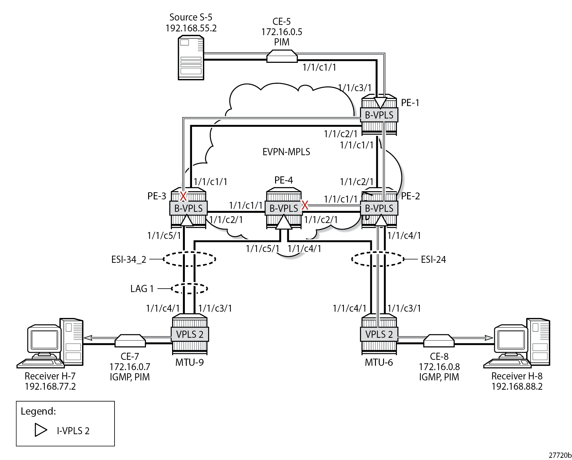
===============================================================================However, PE-4 remains the NDF for both ESs and does not forward any traffic from the B-VPLS EVPN-MPLS interface to the spoke-SDP. PBB-EVPN with MH and PIM Snooping – Receiver H-8 Joined shows the multicast traffic flow when PIM snooping is enabled and receiver H-8 has joined.
Failover
EVPN-MPLS with MH and PIM Snooping – Receivers H-7 and H-8 Joined showed the multicast traffic flow when both H-7 and H-8 have joined the multicast group. PE-2 is the DF for ESI-24 and PE-4 is the DF for ESI-34_2. The following failures are introduced to force a failover from PE-2 to PE-4 and from PE-3 to PE-4. Data-driven PIM state synchronization is used for all-active MH; MCS is configured for fast failover in the single-active MH ES ESI-24.
On MTU-6, SDP 62 is disabled, as follows:
On MTU-6:
configure service sdp 62 shutdown
On MTU-9, port 1/1/c3/1 toward PE-3 is disabled, as follows:
On MTU-9:
configure port 1/1/c3/1 shutdown
Log 99 on PE-3 shows that the DF state in ESI-34_2 changed to false:
184 2023/08/24 14:29:36.634 UTC MINOR: SVCMGR #2095 Base
"Ethernet Segment:ESI-34_2, ISID:2, Designated Forwarding state changed to:false"
PE-4 becomes the DF for both ESs, as follows:
*A:PE-4# show service id 2 ethernet-segment

===============================================================================
SAP Ethernet-Segment Information
===============================================================================
SAP                   Eth-Seg                          Status
-------------------------------------------------------------------------------
lag-1:2               ESI-34_2                         DF
===============================================================================

===============================================================================
SDP Ethernet-Segment Information
===============================================================================
SDP                   Eth-Seg                          Status
-------------------------------------------------------------------------------
46:2                  ESI-24                           DF
===============================================================================
No vxlan instance entries
EVPN-MPLS with MH and PIM Snooping – Multicast Flow after Failover shows the traffic flow after failover to the new DF, PE-4.
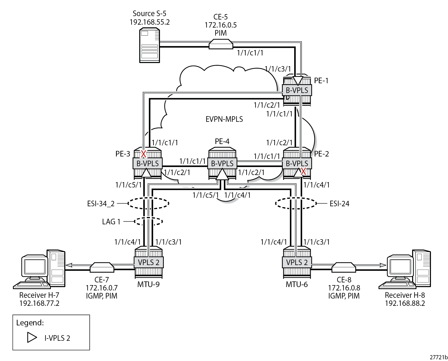
PE-2 receives the multicast stream from PE-1 on port 1/1/c2/1 and forwards it to port 1/1/c1/1 to PE-4; it does not forward to port 1/1/c4/1 because SDP 26 is down, as follows:
*A:PE-2# show port 1/1/c1/1 statistics

===============================================================================
Port Statistics on Slot 1
===============================================================================
Port                        Ingress Packets                  Ingress Octets
Id                           Egress Packets                   Egress Octets
-------------------------------------------------------------------------------
1/1/c1/1                                 63                           11627
                                      16519                        25288008
===============================================================================

*A:PE-2# show port 1/1/c2/1 statistics

===============================================================================
Port Statistics on Slot 1
===============================================================================
Port                        Ingress Packets                  Ingress Octets
Id                           Egress Packets                   Egress Octets
-------------------------------------------------------------------------------
1/1/c2/1                              16478                        25277265
                                         21                            2162
===============================================================================

*A:PE-2# show port 1/1/c3/1 statistics

*A:PE-2# show port 1/1/c4/1 statistics

===============================================================================
Port Statistics on Slot 1
===============================================================================
Port                        Ingress Packets                  Ingress Octets
Id                           Egress Packets                   Egress Octets
-------------------------------------------------------------------------------
1/1/c4/1                                 16                            1703
                                         17                            1908
===============================================================================
PE-4 receives the multicast traffic on port 1/1/c2/1 and forwards it on port 1/1/c4/1 toward MTU-6, and on port 1/1/c5/1 to MTU-9, as follows:
*A:PE-4# show port 1/1/c1/1 statistics

===============================================================================
Port Statistics on Slot 1
===============================================================================
Port                        Ingress Packets                  Ingress Octets
Id                           Egress Packets                   Egress Octets
-------------------------------------------------------------------------------
1/1/c1/1                                 19                            2068
                                         17                            1792
===============================================================================

*A:PE-4# show port 1/1/c2/1 statistics

===============================================================================
Port Statistics on Slot 1
===============================================================================
Port                        Ingress Packets                  Ingress Octets
Id                           Egress Packets                   Egress Octets
-------------------------------------------------------------------------------
1/1/c2/1                              16519                        25288058
                                         62                           11487
===============================================================================

*A:PE-4# show port 1/1/c3/1 statistics

*A:PE-4# show port 1/1/c4/1 statistics

===============================================================================
Port Statistics on Slot 1
===============================================================================
Port                        Ingress Packets                  Ingress Octets
Id                           Egress Packets                   Egress Octets
-------------------------------------------------------------------------------
1/1/c4/1                                 16                            1703
                                      16472                        25113619
===============================================================================

*A:PE-4# show port 1/1/c5/1 statistics

===============================================================================
Port Statistics on Slot 1
===============================================================================
Port                        Ingress Packets                  Ingress Octets
Id                           Egress Packets                   Egress Octets
-------------------------------------------------------------------------------
1/1/c5/1                                 20                            2560
                                      16477                        24752460
===============================================================================
MTU-6 forwards the traffic to CE-8, which forwards it to H-8. MTU-9 forwards the traffic to CE-7, which sends it to H-7. PE-3 drops the multicast traffic because LAG 1 is down because of the failure that was introduced at MTU-9 (port disabled).
Conclusion
PIM snooping reduces flooding of multicast traffic in L2 services and can be used in PBB-EVPN I-VPLSs in the same way as in I-VPLSs using B-VPLS without EVPN. PIM snooping can be used in all-active and single-active MH scenarios with data-driven state synchronization and MCS, respectively.