Static VXLAN Termination in Epipe Services
This chapter provides information about Static VXLAN Termination in Epipe Services.
Topics in this chapter include:
Applicability
This chapter was initially written for SR OS Release 15.0.R6, but the CLI in the current edition is based on SR OS Release 21.5.R1. Static VXLAN termination for Epipe services is supported in SR OS Release 15.0.R1, and later.
Overview
Static Virtual eXtensible Local Area Network (VXLAN) termination on non-system IP addresses of the PEs is supported in VPLS services, as described in chapter VXLAN Forwarding Path Extension, and in Epipe services, as described in this chapter. Whereas VPLSs using VXLAN require BGP-EVPN control plane in the current release, Epipe services using VXLAN do not. This implies that only the configured values are used because no auto-discovery of the remote Termination Endpoints (TEPs) can be done without BGP-EVPN.
This chapter describes the configuration and use of static VXLAN as an access tunneling mechanism to a PBB-EVPN network. This is a design deployed in some service provider networks where the aggregation network is a non-MPLS IP network.
Static VXLAN termination for Epipe services can be applied on system IP addresses or non-system IP addresses.
Static VXLAN termination on system IP addresses
Static VXLAN termination on system IP addresses shows an example topology with three PEs and two CEs. Epipe 1 is configured on PE-1 and PE-2. PE-2 and PE-4 are part of a PBB-EVPN network. On PE-2, a port cross-connect (PXC) is configured to connect the SAP in Epipe 1 and the SAP in I-VPLS 101. CE-10 and CE-40 can send traffic to each other.
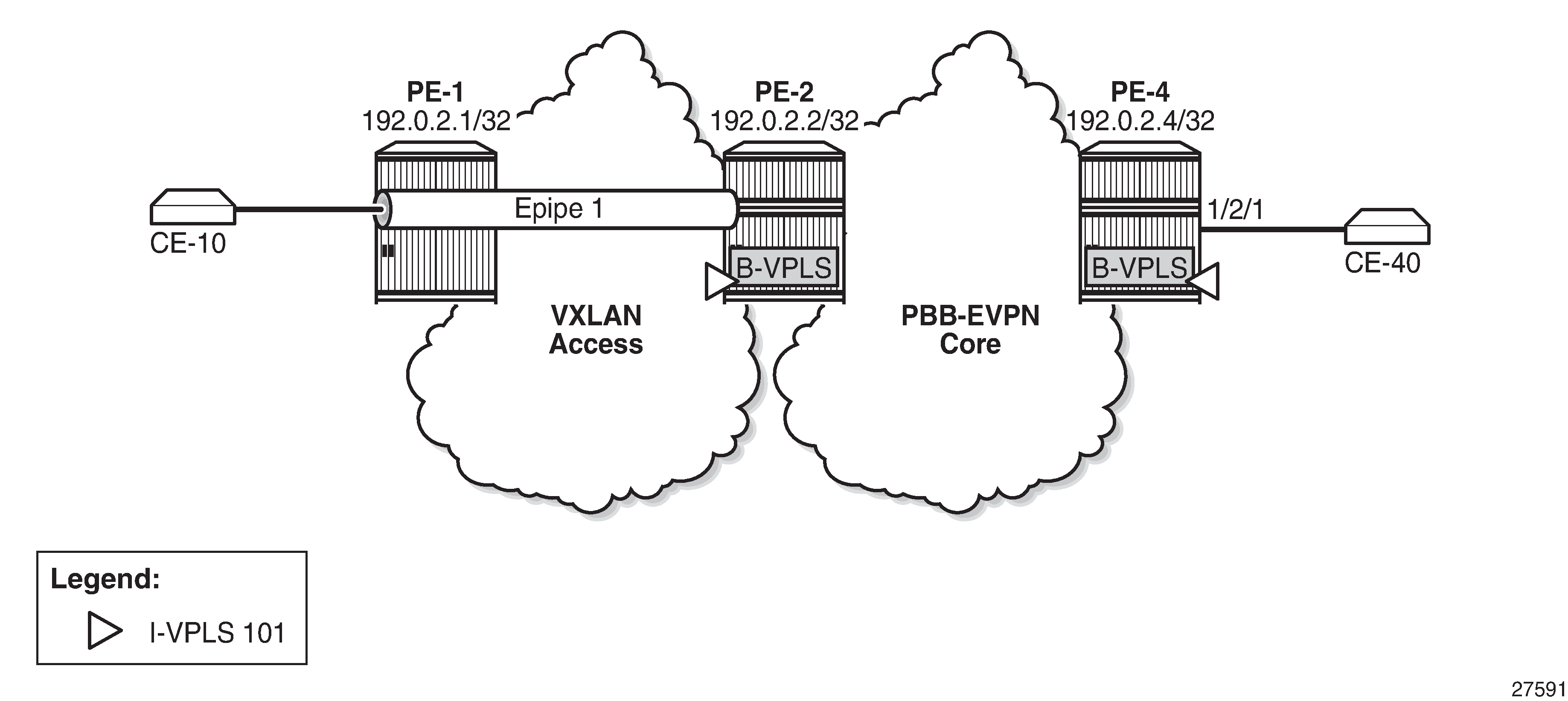
On PE-1, Epipe 1 is configured with egress VXLAN VNI 1, egress VXLAN Termination Endpoint (VTEP) 192.0.2.2, oper-group op-grp-1, and a SAP toward CE-10, as follows:
# on PE-1:
configure
    service
        oper-group "op-grp-1" create
        exit
        epipe 1 name "Epipe 1" customer 1 create
            vxlan instance 1 vni 1 create
                egr-vtep 192.0.2.2
                    oper-group "op-grp-1"
                exit
            exit
            sap 1/2/1:1.* create
                no shutdown
            exit
            no shutdown
        exit
where:
The configured VXLAN Virtual Network Identifier (VNI) is used by the system as follows:
As the egress VNI when sending VXLAN packets for the Epipe service
As the source VNI that identifies the VXLAN packet to be part of the Epipe
Unique in the system, so it can only be configured in one service, either VPLS or Epipe
The configuration of the VXLAN VNI in an Epipe is similar to the configuration of the VXLAN VNI in a VPLS, except that in a VPLS, the VNI is only used as the source VNI, because the egress VNI is learned from BGP-EVPN. However, in Epipe services with static VXLAN, the egress VNI is also the configured VNI.
The egress VTEP is the system IP address of the remote PE. The system will add the configured egress VTEP IP address as the remote VTEP when encapsulating the frames into VXLAN packets. Only the egress VTEP is configured, not the source VTEP. The PE receiving VXLAN packets will not check the source VTEP.
The egress VTEP IP address must be in the Routing Table Manager (RTM). An oper-group is associated with the egress VTEP IP address, so that when the egress VTEP disappears from the base route table, the oper-group is brought operationally down, which propagates the failure to other objects that have this oper-group associated. The status of the oper-group and the service will be as follows:
When the egress VTEP disappears from the RTM, the VXLAN binding goes operationally down and the oper-group associated with the egress VTEP goes operationally down.
When the Epipe SAP goes down, the service goes down too.
When the VXLAN binding goes down, the service remains up as long as the access SAP is up.
When the service is admin shutdown, the VXLAN binding and the oper-group associated with the egress VTEP are both brought operationally down.
Only SAPs can be associated with the Epipe; no spoke-SDPs are supported in SR OS Release 21.5.R1, as follows. Regular SAPs and PXC SAPs are supported.
*A:PE-1>config>service>epipe# spoke-sdp 11:1 create
MINOR: SVCMGR #1957 SDP binding not supported - service has vxlan vtep configured
Frame encapsulation and forwarding
Incoming traffic in the PEs is treated as follows:
For frames received from the SAPs, a SAP lookup identifies all frames matching the configured SAP (on PE-1, SAP 1/2/1:1.*). The matching frames will be encapsulated into VXLAN IPv4 packets with the following fields:
Source VTEP = system IP address
Destination VTEP = configured address in egr-vtep
VNI = configured VXLAN VNI
Source and destination UDP ports will be populated as per the existing VXLAN implementation VPLS services, with the source UDP port populated with the result of a hash on the ingress packets.
For VXLAN frames received from the VXLAN network, a VNI lookup is done for packets with IP DA = system IP address. Frames with the configured VNI 1 are assigned to Epipe 1. The VXLAN encapsulation is removed and the frames are forwarded to the SAP.
Per-service hashing is not supported in Epipe-VXLAN services; only regular hashing and spraying in LAG/ECMP is supported as in any Epipe.
Static VXLAN termination on IPv6 or non-system IPv4 addresses
The non-system IPv4 or IPv6 VXLAN termination on Epipe services is configured in the same way as for VPLS services and described in the VXLAN Forwarding Path Extension chapter, using the FPE function for additional processing. The following steps are required for configuring the FPE for VXLAN termination:
Create FPE.
Associate FPE with VXLAN termination.
Configure the loopback router interface subnet for VXLAN termination and its advertisement into the routing protocol. The subnet can be IPv4 or IPv6.
Configure the loopback address for VXLAN termination.
Add the service configuration.
Configuration
In this section, static VXLAN termination for Epipe services is configured for the following cases:
VXLAN termination on system IP addresses
VXLAN termination on non-system IPv4 addresses
VXLAN termination on IPv6 addresses
Static VXLAN used as access network for PBB-EVPN core: all-active multi-homing
Static VXLAN termination on system IP addresses
Example topology for static VXLAN termination on system IP addresses shows the example topology for static VXLAN termination on system IP addresses. The initial configuration of the PEs includes the cards, MDAs, ports, router interfaces, and IGP. BGP is not required on PE-1; on PE-2 and PE-4, BGP is configured for address family EVPN.
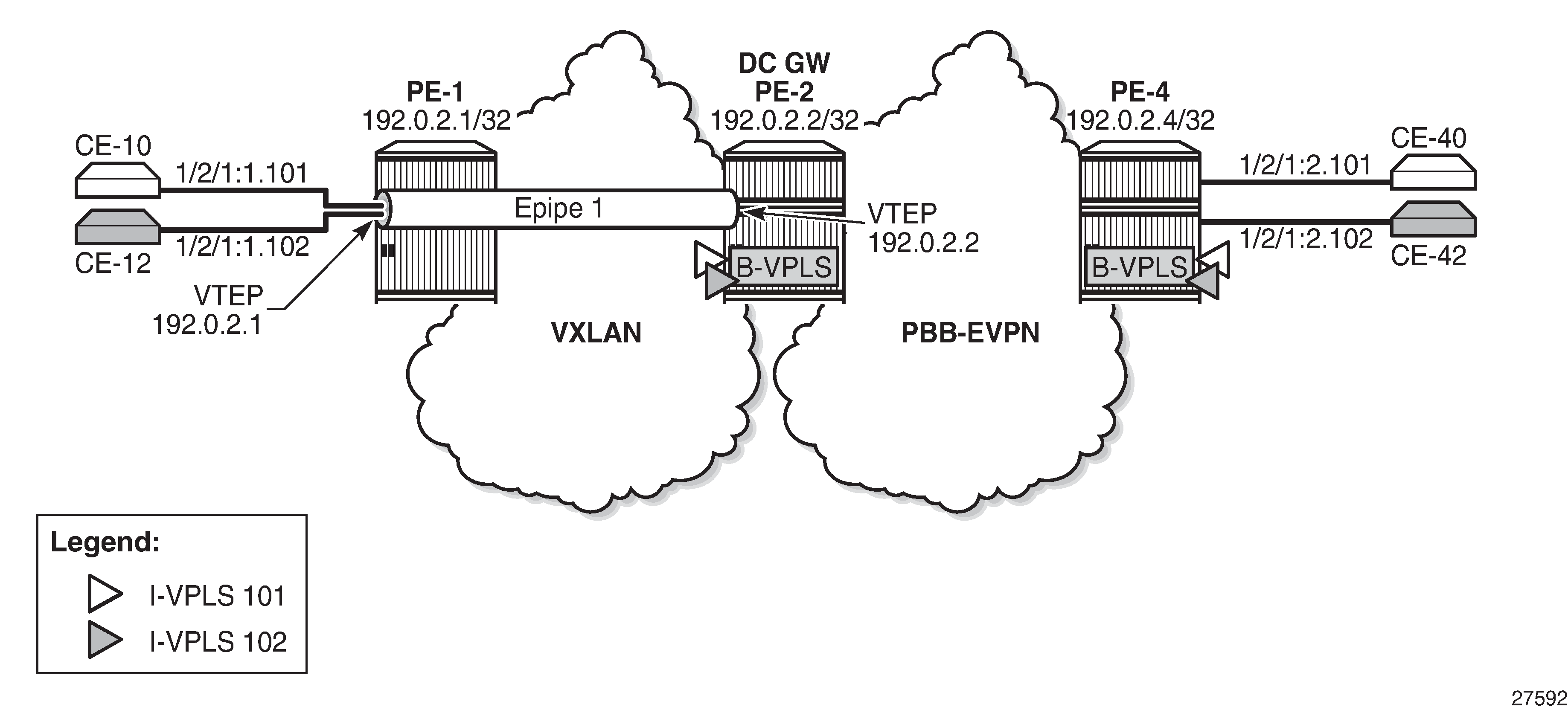
On PE-1, Epipe 1 is configured with egress VXLAN VNI 1, egress VTEP 192.0.2.2, oper-group op-grp-1, and a SAP toward CE-10, as follows. This configuration was explained in the text under Static VXLAN termination on system IP addresses.
# on PE-1:
configure
    service
        oper-group "op-grp-1" create
        exit
        epipe 1 name "Epipe 1" customer 1 create
            vxlan instance 1 vni 1 create
                egr-vtep 192.0.2.2
                    oper-group "op-grp-1"
                exit
            exit
            sap 1/2/1:1.* create
                no shutdown
            exit
            no shutdown
        exit
On PE-2, BGP is configured for address family EVPN, as follows:
# on PE-2:
configure
    router
        autonomous-system 64500
        bgp
            rapid-withdrawal
            split-horizon
            rapid-update evpn
            group "internal"
                family evpn
                peer-as 64500
                neighbor 192.0.2.4
                exit
            exit
There is a PXC configured on port 1/2/1 that will connect SAP pxc-21.a:1.* in Epipe 1, SAP pxc-21.b:1.101 in I-VPLS 101, and SAP pxc-21.b:1.102 in I-VPLS 102. The PXC is configured on PE-2 as follows. See chapter Port Cross-Connect (PXC) for more information.
# on PE-2:
configure
    port-xc
        pxc 21 create
            port 1/2/1
            no shutdown
        exit
    exit
    port pxc-21.a
        ethernet
            encap-type qinq
        exit
        no shutdown
    exit
    port pxc-21.b
        ethernet
            encap-type qinq
        exit
        no shutdown
    exit
    port 1/2/1
        no shutdown
    exit
The service configuration on PE-2 includes Epipe 1, B-VPLS 100, and I-VPLSs 101-102, as follows:
# on PE-2:
configure
    service
        oper-group "op-grp-1" create
        exit
        epipe 1 name "Epipe 1" customer 1 create
            vxlan instance 1 vni 1 create
                egr-vtep 192.0.2.1
                    oper-group "op-grp-1"
                exit
            exit
            sap pxc-21.a:1.* create
                no shutdown
            exit
            no shutdown
        exit
        vpls 100 name "B-VPLS 100" customer 1 b-vpls create
            service-mtu 2000
            pbb
                source-bmac 00:00:00:00:00:02
            exit
            bgp
            exit
            bgp-evpn
                evi 100
                mpls bgp 1
                    ingress-replication-bum-label
                    auto-bind-tunnel
                        resolution any
                    exit
                    no shutdown
                exit
            exit
            stp
                shutdown
            exit
            no shutdown
        exit
        vpls 101 name "I-VPLS 101" customer 1 i-vpls create
            pbb
                backbone-vpls 100
                exit
            exit
            sap pxc-21.b:1.101 create
                no shutdown
            exit
            no shutdown
        exit
        vpls 102 name "I-VPLS 102" customer 1 i-vpls create
            pbb
                backbone-vpls 100
                exit
            exit
            sap pxc-21.b:1.102 create
                no shutdown
            exit
            no shutdown
        exit
The service configuration on PE-4 is similar for the B-VPLS and the I-VPLSs, but Epipe 1 is not configured on PE-4.
The following command shows the VXLAN information for Epipe 1 on PE-1. By default, the source VTEP is the system IP address 192.0.2.1.
*A:PE-1# show service id 1 vxlan
===============================================================================
Vxlan Src Vtep IP: N/A
===============================================================================

===============================================================================
Vxlan Instance
===============================================================================
VXLAN Instance                VNI                      Oper-flags
-------------------------------------------------------------------------------
1                             1                        none
-------------------------------------------------------------------------------
Number of Entries : 1
-------------------------------------------------------------------------------
===============================================================================
*A:PE-1# show service id 1 vxlan destinations

===============================================================================
Egress VTEP, VNI
===============================================================================
VTEP Address                            Egress VNI          Oper      Vxlan
                                                            State     Type
-------------------------------------------------------------------------------
192.0.2.2                               1                   Up        static
-------------------------------------------------------------------------------
Number of Egress VTEP, VNI : 1
-------------------------------------------------------------------------------
===============================================================================
---snip---
The following command shows the oper-group information on PE-1 with the list of egress VTEP members.
*A:PE-1# show service oper-group "op-grp-1" detail

===============================================================================
Service Oper Group Information
===============================================================================
Oper Group       : op-grp-1
Creation Origin  : manual                          Oper Status: up
Hold DownTime    : 0 secs                          Hold UpTime: 4 secs
Members          : 1                               Monitoring : 0
===============================================================================

===============================================================================
Member Egr-Vtep for OperGroup: op-grp-1
===============================================================================
Svc Id              VNI                 VTEP Address
-------------------------------------------------------------------------------
1                   1                   192.0.2.2
-------------------------------------------------------------------------------
Egr-Vtep Entries found: 1
===============================================================================
The oper-group with member egress VTEP 192.0.2.2 cannot be monitored on a SAP in the same Epipe. The following error is raised when attempting to configure the same oper-group for the SAP in Epipe 1 on PE-1:
*A:PE-1>config>service>epipe>sap# oper-group "op-grp-1"
MINOR: SVCMGR #6221 Oper-group can not have monitor and member in the same service
The following ports on PE-2 are disabled to make the destination VTEP unreachable from PE-1:
# on PE-2:
configure
    port 1/1/1
        shutdown
    exit
    port 1/1/2
        shutdown
    exit
When the destination VTEP disappears from the RTM, the oper-group op-grp-1 goes down and the VXLAN binding in Epipe 1 goes down, while the Epipe service remains up, as follows:
*A:PE-1# show service oper-group "op-grp-1"

===============================================================================
Service Oper Group Information
===============================================================================
Oper Group       : op-grp-1
Creation Origin  : manual                          Oper Status: down
Hold DownTime    : 0 secs                          Hold UpTime: 4 secs
Members          : 1                               Monitoring : 0
===============================================================================
*A:PE-1# show service id 1 vxlan destinations

===============================================================================
Egress VTEP, VNI
===============================================================================
VTEP Address                            Egress VNI          Oper      Vxlan
                                                            State     Type
-------------------------------------------------------------------------------
192.0.2.2                               1                   Down      static
-------------------------------------------------------------------------------
Number of Egress VTEP, VNI : 1
-------------------------------------------------------------------------------
===============================================================================
---snip---
*A:PE-1#*A:PE-1# show service id 1 base

===============================================================================
Service Basic Information
===============================================================================
Service Id        : 1                   Vpn Id            : 0
Service Type      : Epipe
---snip---

Admin State       : Up                  Oper State        : Up
---snip---

-------------------------------------------------------------------------------
Service Access & Destination Points
-------------------------------------------------------------------------------
Identifier                               Type         AdmMTU  OprMTU  Adm  Opr
-------------------------------------------------------------------------------
sap:1/2/1:1.*                            qinq         1578    1578    Up   Up
===============================================================================
The output is similar on PE-2. The ports are re-enabled on PE-2, which will cause the VXLAN binding and the oper-group to be operationally up again:
# on PE-2:
configure
    port 1/1/1
        no shutdown
    exit
    port 1/1/2
        no shutdown
    exit
The preceding example proved that the Epipe service remains up when the VXLAN binding goes down. The following example shows that the Epipe service goes down when the SAP goes down. On PE-1, port 1/2/1 is disabled, as follows:
# on PE-1:
configure
    port 1/2/1
        shutdown
The following command shows that SAP 1/2/1:1.* and Epipe 1 are down on PE-1:
*A:PE-1# show service id 1 base

===============================================================================
Service Basic Information
===============================================================================
Service Id        : 1                   Vpn Id            : 0
Service Type      : Epipe
---snip---

Admin State       : Up                  Oper State        : Down
---snip---

-------------------------------------------------------------------------------
Service Access & Destination Points
-------------------------------------------------------------------------------
Identifier                               Type         AdmMTU  OprMTU  Adm  Opr
-------------------------------------------------------------------------------
sap:1/2/1:1.*                            qinq         1578    1578    Up   Down
===============================================================================
The port is re-enabled and SAP 1/2/1:1 and service Epipe 1 will be up again.
# on PE-1:
configure
    port 1/2/1
        no shutdown
When the service is disabled (admin shutdown), the SAP goes down, the VXLAN binding goes down, and the oper-group goes down, as follows:
# on PE-1:
configure
    service
        epipe "Epipe 1"
            shutdown
*A:PE-1# show service id 1 base

===============================================================================
Service Basic Information
===============================================================================
Service Id        : 1                   Vpn Id            : 0
Service Type      : Epipe
---snip---

Admin State       : Down                Oper State        : Down
---snip---

-------------------------------------------------------------------------------
Service Access & Destination Points
-------------------------------------------------------------------------------
Identifier                               Type         AdmMTU  OprMTU  Adm  Opr
-------------------------------------------------------------------------------
sap:1/2/1:1.*                            qinq         1578    1578    Up   Down
===============================================================================
*A:PE-1# show service id 1 vxlan destinations

===============================================================================
Egress VTEP, VNI
===============================================================================
VTEP Address                            Egress VNI          Oper      Vxlan
                                                            State     Type
-------------------------------------------------------------------------------
192.0.2.2                               1                   Down      static
-------------------------------------------------------------------------------
Number of Egress VTEP, VNI : 1
-------------------------------------------------------------------------------
===============================================================================
*A:PE-1# show service oper-group

===============================================================================
Service Oper Group Information
===============================================================================
Name                             Oper   Creation Hold   Hold   Members Monitor
                                 Status Origin   UpTime DnTime
                                                 (secs) (secs)
-------------------------------------------------------------------------------
op-grp-1                         down   manual   4      0      1       0
-------------------------------------------------------------------------------
Entries found: 1
===============================================================================
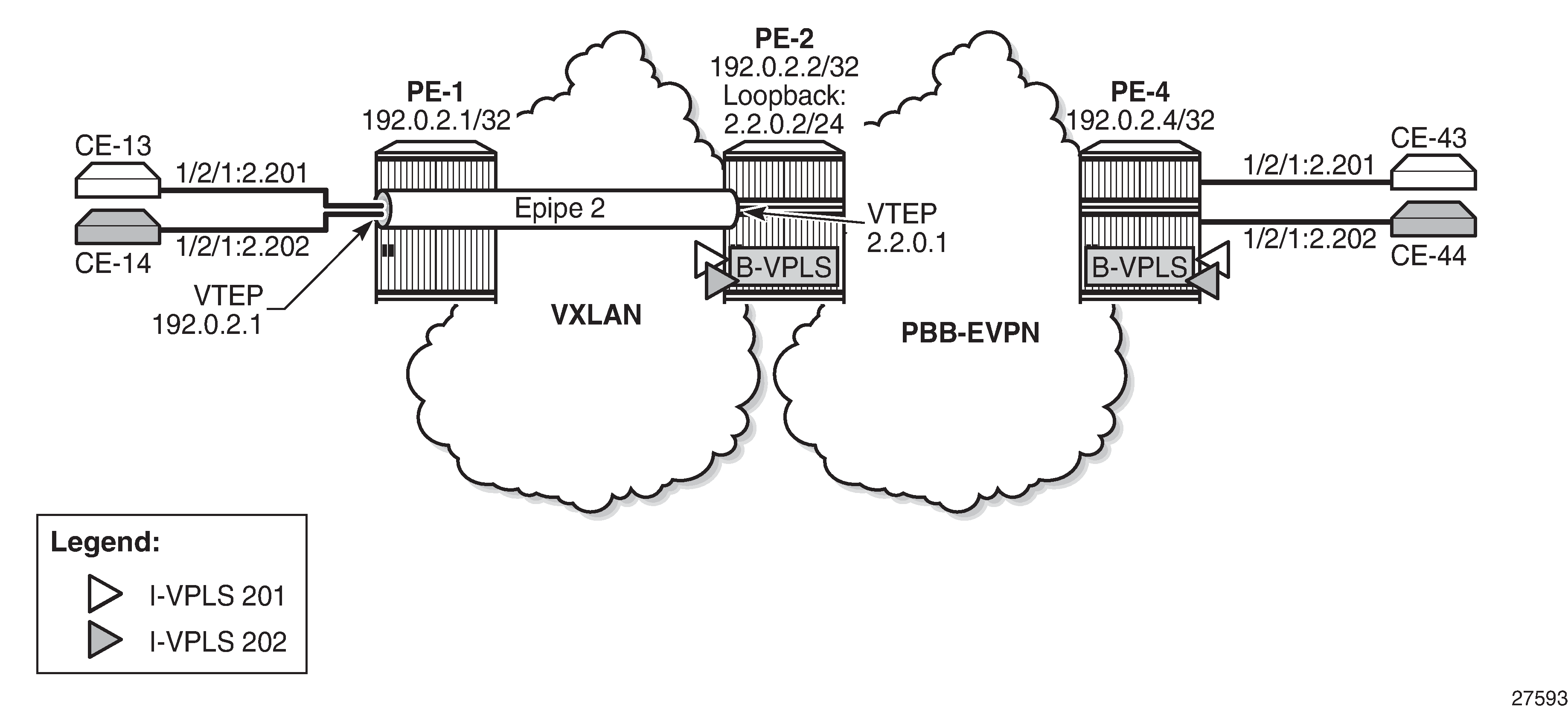
Static VXLAN termination on non-system IPv4 addresses
Non-system IP VXLAN termination is provisioned as follows:
Create FPE
Associate FPE with VXLAN termination
Configure router loopback interface
Configure non-system VXLAN termination VTEP addresses
Add the service configuration
Example topology for static VXLAN termination on non-system IPv4 addresses shows the example topology with PE-1 and PE-2 in a VXLAN network. The non-system loopback address on PE-2 will be used for VXLAN termination, whereas the system IP address will be used on PE-1.
Create FPE
FPE uses the back-to-back PXC, either a PXC port or a LAG-based PXC. The following PXC is created on PE-2:
# on PE-2:
configure
    port-xc
        pxc 1 create
            port 1/2/5
            no shutdown
        exit
The PXC sub-ports and ports are enabled as follows:
# on PE-2:
configure
    port pxc-1.a
        ethernet
            encap-type dot1q
        exit
        no shutdown
    exit
    port pxc-1.b
        ethernet
            encap-type dot1q
        exit
        no shutdown
    exit
    port 1/2/5
        no shutdown
    exit
*A:PE-2# show port pxc 1

===============================================================================
Ports on Port Cross Connect 1
===============================================================================
Port          Admin Link Port    Cfg  Oper LAG/ Port Port Port   C/QS/S/XFP/
Id            State      State   MTU  MTU  Bndl Mode Encp Type   MDIMDX
-------------------------------------------------------------------------------
pxc-1.a       Up    Yes  Up      1574 1574    - hybr dotq xgige
pxc-1.b       Up    Yes  Up      1574 1574    - hybr dotq xgige
===============================================================================
The following FPE uses the PXC:
# on PE-2:
configure
    fwd-path-ext
        fpe 1 create
            path pxc 1
        exit
The following shows that FPE 1 uses PXC 1 and has no VXLAN termination associated:
*A:PE-2# show fwd-path-ext fpe 1

===============================================================================
FPE Id: 1
===============================================================================
Description        : (Not Specified)
Path               : pxc 1
Pw Port            : Disabled                          Oper     : down
Sub Mgmt Extension : Disabled                          Oper     : N/A
Vxlan Termination  : Disabled                          Oper     : down
Segment-Routing V6 : Disabled
===============================================================================
Associate FPE with VXLAN termination
The following command associates FPE 1 with VXLAN termination:
# on PE-2:
configure
    fwd-path-ext
        sdp-id-range from 10000 to 10127
        fpe 1 create
            path pxc 1
            vxlan-termination
        exit
When attempting to associate the FPE with VXLAN termination without configuring a range of SDP IDs for FPE, the following error is raised:
*A:PE-2>config>fwd-path-ext>fpe# vxlan-termination
MINOR: FPE #1021 sdp-id-range is not configured
The following shows the range of SDP IDs for FPE and the list of configured FPEs; see the VXLAN Forwarding Path Extension chapter for more information about the use of SDP IDs. The application for FPE 1 is VXLAN termination.
*A:PE-2# show fwd-path-ext

===============================================================================
FPE Info
===============================================================================
FPE Id                   Path                          Application
                         pxc/xc-a, xc-b
-------------------------------------------------------------------------------
1                        pxc 1                         vxlan-term
-------------------------------------------------------------------------------
Number of entries : 1
-------------------------------------------------------------------------------
SDP-Id Range: 10000 - 10127
===============================================================================
After the FPEs are associated with VXLAN termination, the system creates two internal router interfaces per FPE, one per PXC sub-port, as follows:
*A:PE-2# show router interface

===============================================================================
Interface Table (Router: Base)
===============================================================================
Interface-Name                   Adm       Opr(v4/v6)  Mode    Port/SapId
   IP-Address                                                  PfxState
-------------------------------------------------------------------------------
_tmnx_fpe_1.a                    Up        Up/Up       Network pxc-1.a:1
   fe80::100/64                                                PREFERRED
_tmnx_fpe_1.b                    Up        Up/Up       Network pxc-1.b:1
   fe80::101/64                                                PREFERRED
---snip---
The configuration of the internal interfaces can be verified as follows:
*A:PE-2>config>router# interface "_tmnx_fpe_1.a"
*A:PE-2>config>router>if# info
----------------------------------------------
            port pxc-1.a:1
            mac 00:00:00:00:00:01
            ipv6
                link-local-address fe80::100 dad-disable
                neighbor fe80::101 00:00:00:00:00:02
            exit
            no shutdown
----------------------------------------------
*A:PE-2>config>router# interface "_tmnx_fpe_1.b"
*A:PE-2>config>router>if# info
----------------------------------------------
            port pxc-1.b:1
            mac 00:00:00:00:00:02
            ipv6
                link-local-address fe80::101 dad-disable
                neighbor fe80::100 00:00:00:00:00:01
            exit
            no shutdown
----------------------------------------------
Configure router loopback interface
The following loopback interface is configured in PE-2 and added to the IS-IS context. The IPv6 address is not required yet.
# on PE-2:
configure
    router Base
        interface "loopback1"
            address 2.2.0.2/24
            loopback
            ipv6
                address 220::2/120
            exit
        exit
        isis 0
            interface "loopback1"
                no shutdown
            exit
        exit
A subnet must be assigned to the loopback interface, but not a /32 or /128 subnet mask, because the system cannot terminate VXLAN on a local interface address. In the preceding example, all addresses in the subnet 2.2.0.0/24 can be used for VXLAN tunnel termination, except for 2.2.0.2. The subnet will be advertised by the IGP. The subnet can be as small as /31 or /127.
Configure non-system VTEP addresses
On PE-2, non-system IP address 2.2.0.1 in the subnet of the loopback address 2.2.0.2/24 is configured as VTEP, as follows. Up to three non-system VTEP addresses can be configured to terminate VXLAN tunnels and their corresponding FPEs.
# on PE-2:
configure
    service
        system
            vxlan
                tunnel-termination 2.2.0.1 fpe 1 create
            exit
        exit
No non-system VTEP addresses need to be configured on PE-1.
When the non-system VTEP address is configured, an internal loopback interface _tmnx_vli_vxlan_1_131075 with VTEP address 2.2.0.1/32 is auto-created that can respond to ICMP requests.
*A:PE-2# show router interface

===============================================================================
Interface Table (Router: Base)
===============================================================================
Interface-Name                   Adm       Opr(v4/v6)  Mode    Port/SapId
   IP-Address                                                  PfxState
-------------------------------------------------------------------------------
_tmnx_fpe_1.a                    Up        Up/Up       Network pxc-1.a:1
   fe80::100/64                                                PREFERRED
_tmnx_fpe_1.b                    Up        Up/Up       Network pxc-1.b:1
   fe80::101/64                                                PREFERRED
_tmnx_vli_vxlan_1_131075         Up        Up/Up       Network loopback
   2.2.0.1/32                                                  n/a
   fe80::13:ffff:fe00:0/64                                     PREFERRED
---snip---
The system does not verify if there is a local base router loopback interface with a subnet corresponding to the VTEP address. If a tunnel termination address is configured and the FPE is up, the system will start terminating VXLAN traffic and responding ICMP for that address, regardless of the presence of a loopback in the base router. It is also possible that a non-loopback interface has an IP address in the configured subnet.
Configure the services
Epipe 2 is configured on PE-1 as follows. By default, the system IP address will be used as source VTEP of the VXLAN-encapsulated frames. The non-system IP address 2.2.0.1 is used as egress VTEP.
# on PE-1:
configure
    service
        epipe 2 name "Epipe 2" customer 1 create
            vxlan instance 1 vni 2 create
                egr-vtep 2.2.0.1
                exit
            exit
            sap 1/2/1:2.* create
                no shutdown
            exit
            no shutdown
        exit
The configuration of Epipe 2 on PE-2 defines the non-system IP address 2.2.0.1 as source VTEP, as follows. The egress VTEP is 192.0.2.1, the system IP address of PE-1. The configuration of the B-VPLS is the same as in the preceding example; the configuration of the I-VPLSs 201 and 202 is similar to the configuration of I-VPLS 101 in the preceding example.
# on PE-2:
configure
    service
        epipe 2 name "Epipe 2" customer 1 create
            vxlan-src-vtep 2.2.0.1
            vxlan instance 1 vni 2 create
                egr-vtep 192.0.2.1
                exit
            exit
            sap pxc-21.a:2.* create
                no shutdown
            exit
            no shutdown
        exit
The following show command on PE-1 shows that no VXLAN source VTEP IP address is configured:
*A:PE-1# show service id 2 vxlan
===============================================================================
Vxlan Src Vtep IP: N/A
===============================================================================

===============================================================================
Vxlan Instance
===============================================================================
VXLAN Instance                VNI                      Oper-flags
-------------------------------------------------------------------------------
1                             2                        none
-------------------------------------------------------------------------------
Number of Entries : 1
-------------------------------------------------------------------------------
===============================================================================
The following shows that the egress VTEP is 2.2.0.1, which is a non-system VTEP on PE-2. The VXLAN tunnel is operationally up.
*A:PE-1# show service id 2 vxlan destinations

===============================================================================
Egress VTEP, VNI
===============================================================================
VTEP Address                            Egress VNI          Oper      Vxlan
                                                            State     Type
-------------------------------------------------------------------------------
2.2.0.1                                 2                   Up        static
-------------------------------------------------------------------------------
Number of Egress VTEP, VNI : 1
-------------------------------------------------------------------------------
===============================================================================
---snip---
The same commands on PE-2 show that source VTEP IP address 2.2.0.1 is configured and the egress VTEP is 192.0.2.1, which is the system IP address of PE-1, as follows:
*A:PE-2# show service id 2 vxlan
===============================================================================
Vxlan Src Vtep IP: 2.2.0.1
===============================================================================

===============================================================================
Vxlan Instance
===============================================================================
VXLAN Instance                VNI                      Oper-flags
-------------------------------------------------------------------------------
1                             2                        none
-------------------------------------------------------------------------------
Number of Entries : 1
-------------------------------------------------------------------------------
===============================================================================
*A:PE-2# show service id 2 vxlan destinations

===============================================================================
Egress VTEP, VNI
===============================================================================
VTEP Address                            Egress VNI          Oper      Vxlan
                                                            State     Type
-------------------------------------------------------------------------------
192.0.2.1                               2                   Up        static
-------------------------------------------------------------------------------
Number of Egress VTEP, VNI : 1
-------------------------------------------------------------------------------
===============================================================================
---snip---
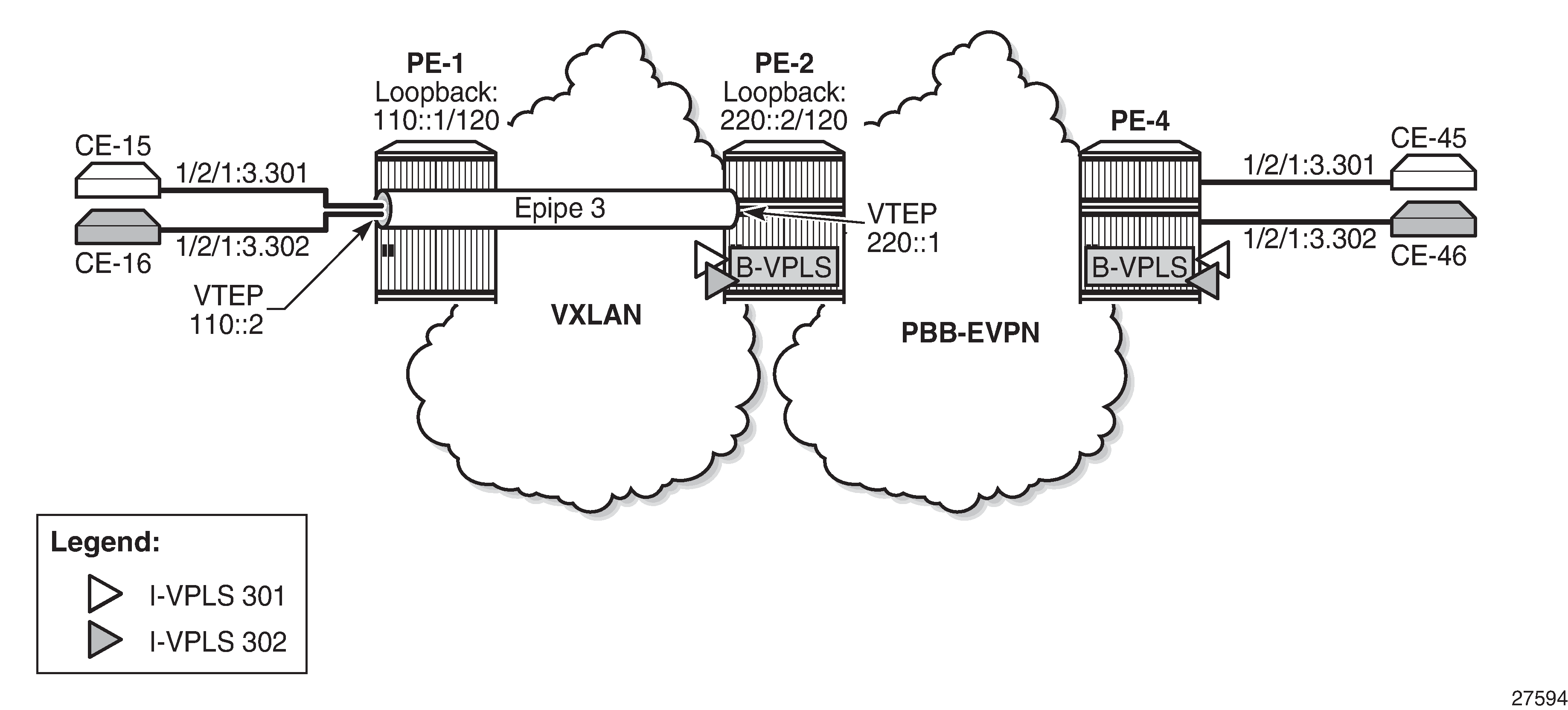
Static VXLAN termination on IPv6 addresses
IPv6 VXLAN termination is provisioned as follows:
Create FPE
Associate FPE with VXLAN termination
Configure router loopback interface
Configure non-system VXLAN termination VTEP addresses
Add the service configuration
Example topology for static VXLAN termination on IPv6 addresses shows the example topology with PE-1 and PE-2 in a VXLAN network. The loopback addresses on PE-1 and PE-2 will be used for IPv6 VXLAN termination. The existing PXC 1 on PE-2 is reused for FPE; only an IPv6 VTEP address needs to be added.
For IPv6 routing, the following option is configured for IS-IS on all nodes:
# on all PEsL
configure
    router Base
        isis 0
            ipv6-routing native
Create FPE
The following PXC is created on PE-1; PXC 1 will be used for FPE:
# on PE-1:
configure
    port-xc
        pxc 1 create
            port 1/2/5
            no shutdown
        exit
The PXC sub-ports and ports are enabled as follows:
# on PE-1:
configure
    port pxc-1.a
        ethernet
            encap-type dot1q
        exit
        no shutdown
    exit
    port pxc-1.b
        ethernet
            encap-type dot1q
        exit
        no shutdown
    exit
    port 1/2/5
        no shutdown
    exit
*A:PE-1# show port pxc 1

===============================================================================
Ports on Port Cross Connect 1
===============================================================================
Port          Admin Link Port    Cfg  Oper LAG/ Port Port Port   C/QS/S/XFP/
Id            State      State   MTU  MTU  Bndl Mode Encp Type   MDIMDX
-------------------------------------------------------------------------------
pxc-1.a       Up    Yes  Up      1574 1574    - hybr dotq xgige
pxc-1.b       Up    Yes  Up      1574 1574    - hybr dotq xgige
===============================================================================
FPE 1 uses PXC 1:
# on PE-1:
configure
    fwd-path-ext
        fpe 1 create
            path pxc 1
        exit
The following shows that FPE 1 uses PXC 1 and has no VXLAN termination associated:
*A:PE-1# show fwd-path-ext fpe 1

===============================================================================
FPE Id: 1
===============================================================================
Description        : (Not Specified)
Path               : pxc 1
Pw Port            : Disabled                          Oper     : down
Sub Mgmt Extension : Disabled                          Oper     : N/A
Vxlan Termination  : Disabled                          Oper     : down
Segment-Routing V6 : Disabled
===============================================================================
Associate FPE with VXLAN termination
The following command associates FPE 1 with VXLAN termination:
# on PE-1:
configure
    fwd-path-ext
        sdp-id-range from 10000 to 10127
        fpe 1 create
            path pxc 1
            vxlan-termination
        exit
The following shows the range of SDP IDs for FPE and the list of configured FPEs. The application for FPE 1 is VXLAN termination.
*A:PE-1# show fwd-path-ext

===============================================================================
FPE Info
===============================================================================
FPE Id                   Path                          Application
                         pxc/xc-a, xc-b
-------------------------------------------------------------------------------
1                        pxc 1                         vxlan-term
-------------------------------------------------------------------------------
Number of entries : 1
-------------------------------------------------------------------------------
SDP-Id Range: 10000 - 10127
===============================================================================
After the FPEs are associated with VXLAN termination, the system creates two internal router interfaces per FPE, one per PXC sub-port, as follows:
*A:PE-1# show router interface

===============================================================================
Interface Table (Router: Base)
===============================================================================
Interface-Name                   Adm       Opr(v4/v6)  Mode    Port/SapId
   IP-Address                                                  PfxState
-------------------------------------------------------------------------------
_tmnx_fpe_1.a                    Up        Up/Up       Network pxc-1.a:1
   fe80::100/64                                                PREFERRED
_tmnx_fpe_1.b                    Up        Up/Up       Network pxc-1.b:1
   fe80::101/64                                                PREFERRED
---snip---
Configure router loopback interface
The following loopback interface is configured in PE-1 and added to the IS-IS context:
# on PE-1:
configure
    router Base
        interface "loopback1"
            address 1.1.0.1/24
            loopback
            ipv6
                address 110::1/120
            exit
        exit
        isis 0
            interface "loopback1"
                no shutdown
            exit
        exit
All IPv6 addresses in the 110::/120 subnet can be used for VXLAN tunnel termination, except for 110::1.
Configure non-system VTEP addresses
On PE-1, IPv6 address 110::2 in the subnet of the loopback address 110::1/120 is configured as VTEP, as follows:
# on PE-1:
configure
    service
        system
            vxlan
                tunnel-termination 110::2 fpe 1 create
            exit
        exit
On PE-2, IPv6 address 220::1 in the subnet of the loopback address 220::2/120 is configured as VTEP, as follows:
# on PE-2:
configure
    service
        system
            vxlan
                tunnel-termination 220::1 fpe 1 create
            exit
        exit
When the IPv6 VTEP address is configured on PE-1, an internal loopback interface _tmnx_vli_vxlan_1_131075 is created, as follows.
*A:PE-1# show router interface

===============================================================================
Interface Table (Router: Base)
===============================================================================
Interface-Name                   Adm       Opr(v4/v6)  Mode    Port/SapId
   IP-Address                                                  PfxState
-------------------------------------------------------------------------------
_tmnx_fpe_1.a                    Up        Up/Up       Network pxc-1.a:1
   fe80::100/64                                                PREFERRED
_tmnx_fpe_1.b                    Up        Up/Up       Network pxc-1.b:1
   fe80::101/64                                                PREFERRED
_tmnx_vli_vxlan_1_131075         Up        Down/Up     Network loopback
   110::2/128                                                  PREFERRED
   fe80::f:ffff:fe00:0/64                                      PREFERRED
---snip---
The following IPv6 route table on PE-1 contains an internal static route for source VTEP 110::2/128 using the FPE internal interface _tmnx_fpe_1.a:
*A:PE-1# show router route-table ipv6

===============================================================================
IPv6 Route Table (Router: Base)
===============================================================================
Dest Prefix[Flags]                            Type    Proto     Age        Pref
      Next Hop[Interface Name]                                    Metric
-------------------------------------------------------------------------------
110::/120                                     Local   Local     01h34m32s  0
       loopback1                                                    0
110::2/128                                    Remote  Static    00h33m20s  5
       fe80::101-"_tmnx_fpe_1.a"                                    1
220::/120                                     Remote  ISIS      00h15m03s  15
       fe80::616:1ff:fe01:2-"int-PE-1-PE-2"                         10
---snip---
The following IPv6 route table on PE-2 shows that an internal static route is configured for the source VTEP 220::1/128 using the FPE internal interface _tmnx_fpe_1.a:
*A:PE-2# show router route-table ipv6

===============================================================================
IPv6 Route Table (Router: Base)
===============================================================================
Dest Prefix[Flags]                            Type    Proto     Age        Pref
      Next Hop[Interface Name]                                    Metric
-------------------------------------------------------------------------------
110::/120                                     Remote  ISIS      00h00m46s  15
       fe80::10:1ff:fe01:1-"int-PE-2-PE-1"                          10
220::/120                                     Local   Local     00h05m08s  0
       loopback1                                                    0
220::1/128                                    Remote  Static    00h00m24s  5
       fe80::101-"_tmnx_fpe_1.a"                                    1
---snip---
Configure the services
Epipe 3 is configured on PE-1 with vxlan-src-vtep 110::2, which is the VTEP address configured in the preceding step (VXLAN tunnel termination). The egress VTEP is 220::1, which is the VXLAN termination configured on PE-2.
# on PE-1:
configure
    service
        epipe 3 name "Epipe 3" customer 1 create
            vxlan-src-vtep 110::2
            vxlan instance 1 vni 3 create
                egr-vtep 220::1
                exit
            exit
            sap 1/2/1:3.* create
                no shutdown
            exit
            no shutdown
        exit
Epipe 3 on PE-2 has VXLAN source VTEP 220::1 and egress VTEP 110::2.
# on PE-2:
configure
    service
        epipe 3 name "Epipe 3" customer 1 create
            vxlan-src-vtep 220::1
            vxlan instance 1 vni 3 create
                egr-vtep 110::2
                exit
            exit
            sap pxc-21.a:3.* create
                no shutdown
            exit
            no shutdown
        exit
The configuration of the B-VPLS is the same as in the preceding example. The configuration of I-VPLS 302 is similar.
# on PE-2:
configure
    service
        vpls 301 name "I-VPLS 301" customer 1 i-vpls create
            pbb
                backbone-vpls 100
                exit
            exit
            sap pxc-21.b:3.301 create
                no shutdown
            exit
            no shutdown
        exit
The following show commands on PE-1 show that the VXLAN source VTEP IP address is 110::2 and the egress VTEP is 220::1. The VXLAN tunnel is operationally up.
*A:PE-1# show service id 3 vxlan
===============================================================================
Vxlan Src Vtep IP: 110::2
===============================================================================

===============================================================================
Vxlan Instance
===============================================================================
VXLAN Instance                VNI                      Oper-flags
-------------------------------------------------------------------------------
1                             3                        none
-------------------------------------------------------------------------------
Number of Entries : 1
-------------------------------------------------------------------------------
===============================================================================
*A:PE-1# show service id 3 vxlan destinations

===============================================================================
Egress VTEP, VNI
===============================================================================
VTEP Address                            Egress VNI          Oper      Vxlan
                                                            State     Type
-------------------------------------------------------------------------------
220::1                                  3                   Up        static
-------------------------------------------------------------------------------
Number of Egress VTEP, VNI : 1
-------------------------------------------------------------------------------
===============================================================================
---snip---
The same commands on PE-2 show VXLAN source VTEP 220::1 and egress VTEP 110::2, as follows:
*A:PE-2# show service id 3 vxlan
===============================================================================
Vxlan Src Vtep IP: 220::1
===============================================================================

===============================================================================
Vxlan Instance
===============================================================================
VXLAN Instance                VNI                      Oper-flags
-------------------------------------------------------------------------------
1                             3                        none
-------------------------------------------------------------------------------
Number of Entries : 1
-------------------------------------------------------------------------------
===============================================================================
*A:PE-2# show service id 3 vxlan destinations

===============================================================================
Egress VTEP, VNI
===============================================================================
VTEP Address                            Egress VNI          Oper      Vxlan
                                                            State     Type
-------------------------------------------------------------------------------
110::2                                  3                   Up        static
-------------------------------------------------------------------------------
Number of Egress VTEP, VNI : 1
-------------------------------------------------------------------------------
===============================================================================
---snip---
Static VXLAN used as access network for PBB-EVPN core: all-active multi-homing and anycast VTEPs
Example topology for static VXLAN termination using anycast shows the example topology with PE-1, PE-2, and PE-3 in the VXLAN access network. Epipe 4 is configured on PE-1, PE-2, and PE-3. On PE-1, the system IP address 192.0.2.1 is used as source VTEP, while (anycast) IP address 23.23.23.4 is used as source VTEP on PE-2 and PE-3.
In the PBB-EVPN core network, all-active multi-homing virtual Ethernet segments vES-23_401 and vES-23_402 are configured on PE-2 and PE-3.
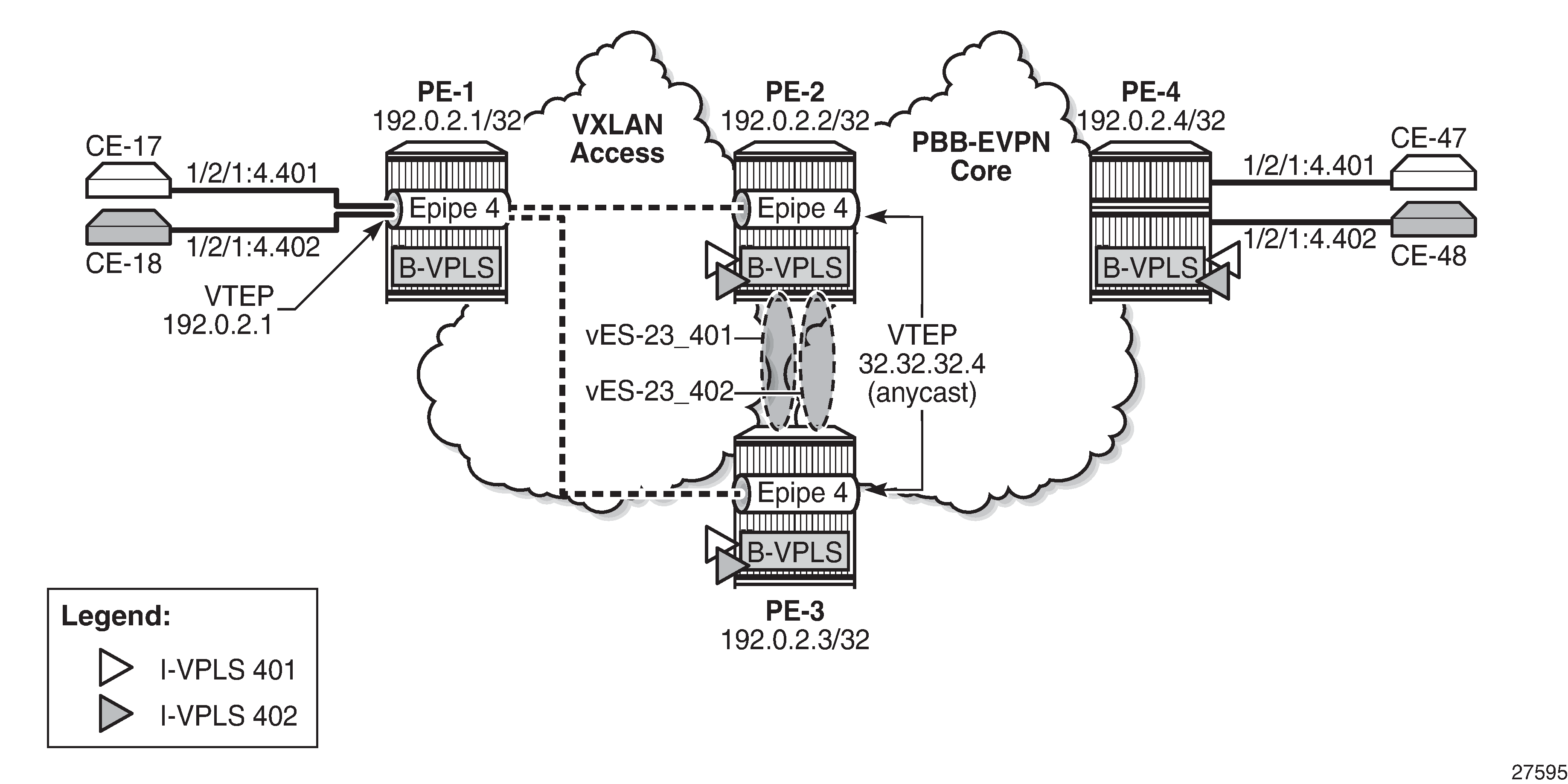
VXLAN access network
On PE-2 and PE-3, PXC ports are configured: PXC 2 will be used as FPE, whereas PXC-3 and PXC-4 will be used to make a LAG for the PXC between Epipe and I-VPLS services. The configuration of the PXC ports is as follows:
# on PE-2, PE-3:
configure
    port-xc
        pxc 2 create
            port 1/2/6
            no shutdown
        exit
        pxc 3 create
            port 1/2/7
            no shutdown
        exit
        pxc 4 create
            port 1/2/8
            no shutdown
        exit
The PXC sub-ports for FPE have dot1q encapsulation whereas the PXC sub-ports for port cross-connect have qinq encapsulation. The sub-ports and ports are enabled, as follows:
# on PE-2, PE-3:
configure
    port pxc-2.a
        ethernet
            encap-type dot1q
        exit
        no shutdown
    exit
    port pxc-2.b
        ethernet
            encap-type dot1q
        exit
        no shutdown
    exit
    port pxc-3.a
        ethernet
            encap-type qinq
        exit
        no shutdown
    exit
    port pxc-3.b
        ethernet
            encap-type qinq
        exit
        no shutdown
    exit
    port pxc-4.a
        ethernet
            encap-type qinq
        exit
        no shutdown
    exit
    port pxc-4.b
        ethernet
            encap-type qinq
        exit
        no shutdown
    exit all
    port 1/2/6
        no shutdown
    exit
    port 1/2/7
        no shutdown
    exit
    port 1/2/8
        no shutdown
    exit
On PE-2 and PE-3, FPE 2 is configured as follows:
# on PE-2, PE-3:
configure
    fwd-path-ext
        fpe 2 create
            path pxc 2
        exit
FPE 2 is associated with VXLAN termination and two internal interfaces will be auto-created: _tmnx_fpe_2.a and _tmnx_fpe_2.b.
# on PE-2, PE-3:
configure
    fwd-path-ext
        sdp-id-range from 10000 to 10127
        fpe 2 create
            path pxc 2
            vxlan-termination
        exit
*A:PE-2# show router interface

===============================================================================
Interface Table (Router: Base)
===============================================================================
Interface-Name                   Adm       Opr(v4/v6)  Mode    Port/SapId
   IP-Address                                                  PfxState
-------------------------------------------------------------------------------
_tmnx_fpe_1.a                    Up        Up/Up       Network pxc-1.a:1
   fe80::100/64                                                PREFERRED
_tmnx_fpe_1.b                    Up        Up/Up       Network pxc-1.b:1
   fe80::101/64                                                PREFERRED
_tmnx_fpe_2.a                    Up        Up/Up       Network pxc-2.a:1
   fe80::200/64                                                PREFERRED
_tmnx_fpe_2.b                    Up        Up/Up       Network pxc-2.b:1
   fe80::201/64                                                PREFERRED
---snip---
A router loopback interface with IP address 23.23.23.2/24 is created on PE-2, and on PE-3 with IP address 23.23.23.3/24:
# on PE-2:
configure
    router Base
        interface "loopback2"
            address 23.23.23.2/24
            loopback
            no shutdown
        exit
        isis 0
            interface "loopback2"
                no shutdown
            exit
        exit
On PE-2 and PE-3, the VTEP 23.23.23.4 is configured for FPE 2, as follows:
# on PE-2, PE-3:
configure
    service
        system
            vxlan
                tunnel-termination 23.23.23.4 fpe 2 create
            exit
The following command shows an additional VTEP 23.23.23.4 to the existing router interface _tmnx_vli_vxlan_1_131075 on PE-2:
*A:PE-2# show router interface "_tmnx_vli_vxlan_1_131075"

===============================================================================
Interface Table (Router: Base)
===============================================================================
Interface-Name                   Adm       Opr(v4/v6)  Mode    Port/SapId
   IP-Address                                                  PfxState
-------------------------------------------------------------------------------
_tmnx_vli_vxlan_1_131075         Up        Up/Up       Network loopback
   2.2.0.1/32                                                  n/a
   220::1/128                                                  PREFERRED
   23.23.23.4/32                                               n/a
   fe80::13:ffff:fe00:0/64                                     PREFERRED
-------------------------------------------------------------------------------
Interfaces : 1
===============================================================================
On PE-2 and PE-3, the VXLAN Epipe 4 uses LAG 4 (composed of pxc-3.b and pxc-4.b) to extend the VXLAN toward the I-VPLSs 401 and 402. The I-VPLS SAPs use LAG 3 (composed of pxc-3.a and pxc-4.a). The PXC LAGs provide higher bandwidth and better resiliency. The LAGs are configured as follows on both PE-2 and PE-3:
# on PE-2, PE-3:
configure
    lag 3
        mode hybrid
        encap-type qinq
        port pxc-3.a
        port pxc-4.a
        no shutdown
    exit
    lag 4
        mode hybrid
        encap-type qinq
        port pxc-3.b
        port pxc-4.b
        no shutdown
    exit
Epipe 4 is configured on PE-1, PE-2, and PE-3. On PE-1, no FPE is required because the system IP address is used as VTEP. Epipe 4 is configured on PE-1 with egress VTEP 23.23.23.4, as follows:
# on PE-1:
configure
    service
        epipe 4 name "Epipe 4" customer 1 create
            vxlan instance 1 vni 4 create
                egr-vtep 23.23.23.4
                exit
            exit
            sap 1/2/1:4.* create
                no shutdown
            exit
            no shutdown
        exit
Epipe 4 is configured on PE-2 and PE-3 with source VTEP 23.23.23.4 and egress VTEP 192.0.2.1, as follows. The SAP uses LAG 4, which is composed of PXC sub-ports pxc-3.b and pxc-4.b.
# on PE-2, PE-3:
configure
    service
        epipe 4 name "Epipe 4" customer 1 create
            vxlan-src-vtep 23.23.23.4
            vxlan instance 1 vni 4 create
                egr-vtep 192.0.2.1
                exit
            exit
            sap lag-4:4.* create
                no shutdown
            exit
            no shutdown
        exit
The following command on PE-1 shows that the egress VTEP in Epipe 4 equals 23.23.23.4.
*A:PE-1# show service id 4 vxlan destinations

===============================================================================
Egress VTEP, VNI
===============================================================================
VTEP Address                            Egress VNI          Oper      Vxlan
                                                            State     Type
-------------------------------------------------------------------------------
23.23.23.4                              4                   Up        static
-------------------------------------------------------------------------------
Number of Egress VTEP, VNI : 1
-------------------------------------------------------------------------------
===============================================================================
---snip---
The following commands for Epipe 4 on PE-2 show a source VTEP equal to 23.23.23.4 and an egress VTEP equal to the system address of PE-1 (192.0.2.1), as follows:
*A:PE-2# show service id 4 vxlan
===============================================================================
Vxlan Src Vtep IP: 23.23.23.4
===============================================================================

===============================================================================
Vxlan Instance
===============================================================================
VXLAN Instance                VNI                      Oper-flags
-------------------------------------------------------------------------------
1                             4                        none
-------------------------------------------------------------------------------
Number of Entries : 1
-------------------------------------------------------------------------------
===============================================================================
*A:PE-2# show service id 4 vxlan destinations

===============================================================================
Egress VTEP, VNI
===============================================================================
VTEP Address                            Egress VNI          Oper      Vxlan
                                                            State     Type
-------------------------------------------------------------------------------
192.0.2.1                               4                   Up        static
-------------------------------------------------------------------------------
Number of Egress VTEP, VNI : 1
-------------------------------------------------------------------------------
===============================================================================
---snip---
The output on PE-3 is identical: source VTEP 23.23.23.4 and egress VTEP 192.0.2.1.
The following route table on PE-1 shows that the best route toward 23.23.23.4 is via PE-2:
*A:PE-1# show router route-table 23.23.23.4

===============================================================================
Route Table (Router: Base)
===============================================================================
Dest Prefix[Flags]                            Type    Proto     Age        Pref
      Next Hop[Interface Name]                                    Metric
-------------------------------------------------------------------------------
23.23.23.0/24                                 Remote  ISIS      00h04m13s  15
       192.168.12.2                                                 10
-------------------------------------------------------------------------------
No. of Routes: 1
Flags: n = Number of times nexthop is repeated
       B = BGP backup route available
       L = LFA nexthop available
       S = Sticky ECMP requested
===============================================================================
PBB-EVPN core network
Two all-active multi-homing virtual ESs are configured on PE-2 and PE-3. The preference for the DF election is configured manually, with opposite preference values for the vESs so that DF load balancing is achieved. While vES-23_401 has preference 5000 on PE-2 and preference 10000 on PE-3, vES-23_402 has preference 10000 on PE-2 and preference 5000 on PE-3. When no event has occurred that caused a DF switchover, PE-2 is DF for vES-23_402 and PE-3 is DF for vES-23_401. Both vESs use LAG 3, which is composed of pxc-3.a and pxc-4.a. For vES-23_401, the qinq encapsulation must match S-tag 4 and C-tag 401; for vES-23_402, the S-tag must be 4 and the C-tag 402. On PE-2, the vESs are configured as follows.
# on PE-2:
configure
    service
        system
            bgp-evpn
                ethernet-segment "vES-23_401" virtual create
                    esi 01:00:00:00:23:04:01:00:00:01
                    source-bmac-lsb 23-41 es-bmac-table-size 8
                    service-carving
                        mode manual
                        manual
                            preference non-revertive create
                                value 5000
                            exit
                        exit
                    exit
                    multi-homing all-active
                    lag 3
                    qinq
                        s-tag 4 c-tag-range 401
                    exit
                    no shutdown
                exit
                ethernet-segment "vES-23_402" virtual create
                    esi 01:00:00:00:23:04:02:00:00:01
                    source-bmac-lsb 23-42 es-bmac-table-size 8
                    service-carving
                        mode manual
                        manual
                            preference non-revertive create
                                value 10000
                            exit
                        exit
                    exit
                    multi-homing all-active
                    lag 3
                    qinq
                        s-tag 4 c-tag-range 402
                    exit
                    no shutdown
                exit
The B-VPLS 100 is configured to use the ES-BMAC. On PE-2, the B-VPLS is configured as follows.
# on PE-2:
configure
    service
        vpls 100 name "B-VPLS 100" customer 1 b-vpls create
            service-mtu 2000
            pbb
                source-bmac 00:00:00:00:00:02
                use-es-bmac
            exit
            bgp
            exit
            bgp-evpn
                evi 100
                mpls bgp 1
                    auto-bind-tunnel
                        resolution any
                    exit
                    no shutdown
                exit
            exit
            no shutdown
On PE-4, the following configuration sets ECMP to a value of 2 in the bgp-evpn mpls context of the B-VPLS, so that aliasing is possible.
# on PE-4:
configure
    service
        vpls "B-VPLS 100"
            bgp-evpn
                mpls
                    ecmp 2
On PE-2 and PE-3, the I-VPLSs are configured with SAP LAG 3, which is composed of pxc-3.a and pxc-4.a, as follows. The qinq encapsulation 4.401 in I-VPLS 401 matches the condition in vES-23_401, whereas qinq 4.402 in I-VPLS 402 matches vES-23_402.
# on PE-2, PE-3:
configure
    service
        vpls 401 name "I-VPLS 401" customer 1 i-vpls create
            pbb
                backbone-vpls 100
                exit
            exit
            sap lag-3:4.401 create
                no shutdown
            exit
            no shutdown
        exit
        vpls 402 name "I-VPLS 402" customer 1 i-vpls create
            pbb
                backbone-vpls 100
                exit
            exit
            sap lag-3:4.402 create
                no shutdown
            exit
            no shutdown
        exit
With the preceding configuration, PBB-EVPN all-active multi-homing and the anycast VTEP at the access VXLAN network can be combined for an efficient and fully redundant network. PE-4 can alias the known unicast traffic to PE-2 and PE-3 on a per-flow basis, whereas if ECMP (and shared queuing) is enabled on PE-1, traffic can also be load-balanced to PE-2 and PE-3. BUM traffic sent from PE-4 will be forwarded by the corresponding DF for the ES.
See chapter EVPN for PBB over MPLS (PBB-EVPN) for more information about PBB-EVPN and all-active multi-homing.
Verification
The following command shows that PE-2 is NDF in vES-23_401 in I-VPLS 401:
*A:PE-2# show service id 401 ethernet-segment

===============================================================================
SAP Ethernet-Segment Information
===============================================================================
SAP                   Eth-Seg                          Status
-------------------------------------------------------------------------------
lag-3:4.401           vES-23_401                       NDF
===============================================================================
No sdp entries
No vxlan instance entries
For I-VPLS 402, PE-2 is DF, as follows:
*A:PE-2# show service id 402 ethernet-segment

===============================================================================
SAP Ethernet-Segment Information
===============================================================================
SAP                   Eth-Seg                          Status
-------------------------------------------------------------------------------
lag-3:4.402           vES-23_402                       DF
===============================================================================
No sdp entries
No vxlan instance entries
For PE-3, the reverse is true: PE-3 is DF in vES-23_401 for I-VPLS 401 and NDF in vES-23_402 for I-VPLS 402.
Within B-VPLS 100, the BMAC addresses are advertised via BGP-EVPN. On PE-2, the following FDB for B-VPLS 100 contains the BMAC addresses of PE-3 and PE-4, which are advertised via BGP-EVPN:
*A:PE-2# show service id 100 fdb detail

===============================================================================
Forwarding Database, Service 100
===============================================================================
ServId     MAC               Source-Identifier       Type     Last Change
            Transport:Tnl-Id                         Age
-------------------------------------------------------------------------------
100        00:00:00:00:00:03 mpls:                   EvpnS:P  06/08/21 15:01:37
                             192.0.2.3:524279
           ldp:65540
100        00:00:00:00:00:04 mpls:                   EvpnS:P  06/08/21 15:01:37
                             192.0.2.4:524283
           ldp:65538
-------------------------------------------------------------------------------
No. of MAC Entries: 2
-------------------------------------------------------------------------------
Legend:  L=Learned O=Oam P=Protected-MAC C=Conditional S=Static Lf=Leaf
===============================================================================
Likewise, the following FDB for B-VPLS 100 on PE-3 contains the BMAC addresses of PE-2 and PE-4:
*A:PE-3# show service id 100 fdb detail

===============================================================================
Forwarding Database, Service 100
===============================================================================
ServId     MAC               Source-Identifier       Type     Last Change
            Transport:Tnl-Id                         Age
-------------------------------------------------------------------------------
100        00:00:00:00:00:02 mpls:                   EvpnS:P  06/08/21 15:16:08
                             192.0.2.2:524283
           ldp:65537
100        00:00:00:00:00:04 mpls:                   EvpnS:P  06/08/21 15:16:08
                             192.0.2.4:524283
           ldp:65539
-------------------------------------------------------------------------------
No. of MAC Entries: 2
-------------------------------------------------------------------------------
Legend:  L=Learned O=Oam P=Protected-MAC C=Conditional S=Static Lf=Leaf
===============================================================================
The following FDB for B-VPLS 100 on PE-4 contains the BMAC addresses of PE-2 and PE-3, but also the BMAC addresses of vES-23_401 and vES-23_402:
*A:PE-4# show service id 100 fdb detail

===============================================================================
Forwarding Database, Service 100
===============================================================================
ServId     MAC               Source-Identifier       Type     Last Change
            Transport:Tnl-Id                         Age
-------------------------------------------------------------------------------
100        00:00:00:00:00:02 mpls:                   EvpnS:P  06/08/21 14:09:43
                             192.0.2.2:524283
           ldp:65538
100        00:00:00:00:00:03 mpls:                   EvpnS:P  06/08/21 14:50:11
                             192.0.2.3:524279
           ldp:65540
100        00:00:00:00:23:41 eES:                    EvpnS:P  06/08/21 14:50:02
                             MAX-ESI
100        00:00:00:00:23:42 eES:                    EvpnS:P  06/08/21 14:50:02
                             MAX-ESI
-------------------------------------------------------------------------------
No. of MAC Entries: 4
-------------------------------------------------------------------------------
Legend:  L=Learned O=Oam P=Protected-MAC C=Conditional S=Static Lf=Leaf
===============================================================================
On PE-4, the following list of BGP EVPN routes for ES-BMAC 00:00:00:00:23:41 of vES-23_401 shows that PE-4 learned the ES-BMAC address via two PEs: PE-2 and PE-3.
*A:PE-4# show router bgp routes evpn mac mac-address 00:00:00:00:23:41
===============================================================================
 BGP Router ID:192.0.2.4        AS:64500       Local AS:64500
===============================================================================
 Legend -
 Status codes  : u - used, s - suppressed, h - history, d - decayed, * - valid
                 l - leaked, x - stale, > - best, b - backup, p - purge
 Origin codes  : i - IGP, e - EGP, ? - incomplete

===============================================================================
BGP EVPN MAC Routes
===============================================================================
Flag  Route Dist.         MacAddr           ESI
      Tag                 Mac Mobility      Label1
                          Ip Address
                          NextHop
-------------------------------------------------------------------------------
u*>i  192.0.2.2:100       00:00:00:00:23:41 ESI-MAX
      0                   Static            LABEL 524283
                          n/a
                          192.0.2.2

u*>i  192.0.2.3:100       00:00:00:00:23:41 ESI-MAX
      0                   Static            LABEL 524279
                          n/a
                          192.0.2.3

-------------------------------------------------------------------------------
Routes : 2
===============================================================================
PE-4 also learned ES-BMAC 00:00:00:00:23:42 via PE-2 and PE-3, as follows:
*A:PE-4# show router bgp routes evpn mac mac-address 00:00:00:00:23:42
===============================================================================
 BGP Router ID:192.0.2.4        AS:64500       Local AS:64500
===============================================================================
 Legend -
 Status codes  : u - used, s - suppressed, h - history, d - decayed, * - valid
                 l - leaked, x - stale, > - best, b - backup, p - purge
 Origin codes  : i - IGP, e - EGP, ? - incomplete

===============================================================================
BGP EVPN MAC Routes
===============================================================================
Flag  Route Dist.         MacAddr           ESI
      Tag                 Mac Mobility      Label1
                          Ip Address
                          NextHop
-------------------------------------------------------------------------------
u*>i  192.0.2.2:100       00:00:00:00:23:42 ESI-MAX
      0                   Static            LABEL 524283
                          n/a
                          192.0.2.2

u*>i  192.0.2.3:100       00:00:00:00:23:42 ESI-MAX
      0                   Static            LABEL 524279
                          n/a
                          192.0.2.3

-------------------------------------------------------------------------------
Routes : 2
===============================================================================
When a ping is initiated from CE-17 to CE-47, the ICMP packets are forwarded from PE-1 to PE-2, because the best route to 23.23.23.4 is via PE-2. PE-2 learns MAC address ca:fe:01:17:17:17 of CE-17 on the local I-VPLS SAP. PE-2 forwards the ICMP packets through I-VPLS 401 and B-VPLS 100 toward PE-4. PE-4 learns MAC ca:fe:01:17:17:17 of CE-17 via the ES-BMAC. When the reply is sent, PE-4 learns MAC address ca:fe:04:47:47:47 of CE-47 on the local SAP.
The FDB for I-VPLS 401 on PE-2 shows that MAC ca:fe:04:47:47:47 is learned on the local SAP and MAC ca:fe:04:47:47:47 can be reached via the B-VPLS to PE-4.
*A:PE-2# show service id 401 fdb detail

===============================================================================
Forwarding Database, Service 401
===============================================================================
ServId     MAC               Source-Identifier       Type     Last Change
            Transport:Tnl-Id                         Age
-------------------------------------------------------------------------------
401        ca:fe:01:17:17:17 sap:lag-3:4.401         L/0      06/08/21 15:19:19
401        ca:fe:04:47:47:47 b-mpls:                 L/0      06/08/21 15:19:19
                             192.0.2.4:524283
           ldp:65538
-------------------------------------------------------------------------------
No. of MAC Entries: 2
-------------------------------------------------------------------------------
Legend:  L=Learned O=Oam P=Protected-MAC C=Conditional S=Static Lf=Leaf
===============================================================================
The following FDB for I-VPLS 401 on PE-3 shows that MAC ca:fe:04:47:47:47 is learned via BGP-EVPN from PE-4.
*A:PE-3# show service id 401 fdb detail
===============================================================================
Forwarding Database, Service 401
===============================================================================
ServId     MAC               Source-Identifier       Type     Last Change
            Transport:Tnl-Id                         Age
-------------------------------------------------------------------------------
401        ca:fe:04:47:47:47 b-mpls:                 L/0      06/08/21 15:19:19
                             192.0.2.4:524283
           ldp:65539
-------------------------------------------------------------------------------
No. of MAC Entries: 1
-------------------------------------------------------------------------------
Legend:  L=Learned O=Oam P=Protected-MAC C=Conditional S=Static Lf=Leaf
===============================================================================
The following FDB for I-VPLS 401 on PE-4 shows that MAC ca:fe:04:47:47:47 is learned on a local SAP, whereas MAC ca:fe:01:17:17:17 is learned via ES-BMAC 00:00:00:00:23:41 of vES-23_401.
*A:PE-4# show service id 401 fdb detail
===============================================================================
Forwarding Database, Service 401
===============================================================================
ServId     MAC               Source-Identifier       Type     Last Change
            Transport:Tnl-Id                         Age
-------------------------------------------------------------------------------
401        ca:fe:01:17:17:17 eES-BMAC:               L/0      06/08/21 15:19:19
                             00:00:00:00:23:41
401        ca:fe:04:47:47:47 sap:1/2/1:4.401         L/0      06/08/21 15:19:19
-------------------------------------------------------------------------------
No. of MAC Entries: 2
-------------------------------------------------------------------------------
Legend:  L=Learned O=Oam P=Protected-MAC C=Conditional S=Static Lf=Leaf
===============================================================================
Conclusion
VXLAN FPE is required to terminate non-system IPv4/IPv6 VXLAN tunnels. The examples in this chapter show how VXLAN FPE can be applied in Epipe services, to stitch static VXLAN to other services, such as I-VPLS services.