EVPN Multi-Homing for VXLAN VPLS Services
This chapter provides information about EVPN Multi-Homing for VXLAN VPLS Services.
Topics in this chapter include:
Applicability
The information and configuration in this chapter are based on SR OS Release 21.7.R1.
EVPN multi-homing has been supported in SR OS for EVPN-MPLS and PBB-EVPN in SR OS Release 13.0.R4 and later. SR OS Release 16.0 introduced EVPN multi-homing for EVPN-VXLAN on Epipe services. EVPN-VXLAN multi-homing in a single VXLAN instance VPLS or R-VPLS service—as specified in RFC 8365—is supported in SR OS Release 19.5.R1, and later.
Before you read this chapter, ensure you are familiar with the concepts in the EVPN for VXLAN Tunnels (Layer 2) chapter.
Overview
Some Service Providers are deploying large Telco cloud Data Centers (DCs) where SR OS nodes are used as leaf switches in a VXLAN fabric. In those cases, all-active multi-homing can provide redundancy and maximize the bandwidth use.
The multi-homing procedures consist of three components:
Designated Forwarder (DF) election
The PEs attached to the same Ethernet Segment (ES) elect a single PE as DF to:
forward all traffic, in case of single-active mode
forward all Broadcast, Unknown unicast, Multicast (BUM) traffic, in case of all-active mode
split-horizon
BUM traffic received from a peer ES PE is filtered so that it is not looped back to the CE that first transmitted the frame.
in EVPN-VXLAN services, split-horizon is only used with all-active mode and makes use of the local bias procedure described in RFC 8365.
aliasing
PEs that are not attached to the ES can process non-zero Ethernet Segment Identifier (ESI) MAC/IP routes and AD routes and create ES destinations to which per-flow Equal Cost Multi-Path (ECMP) can be applied.
Aliasing only applies to all-active mode.
Split-horizon using local bias
In EVPN-MPLS services, split-horizon filtering uses ESI labels. VXLAN does not support ESI labels or MPLS labels. In EVPN-VXLAN services, the split-horizon filtering is based on the tunnel source IP address. In RFC 8365, this forwarding is referred to as local bias. Local bias works as follows:
Every PE knows the IP addresses associated with the other PEs with which it has shared multi-homed ESs.
The ingress PE replicates locally to all directly attached ESs, regardless of the DF state, for all flooded traffic coming from the access interfaces. BUM frames received on any SAP are flooded to:
local non-ES SAPs and non-ES SDP bindings
local all-active ES SAPs (DF and NDF)
local single-active ES SDP bindings and SAPs (DF only)
EVPN-VXLAN destinations
When an egress PE receives a BUM frame from a VXLAN binding, it looks up the source IP address in the tunnel header and filters out the frame on all local interfaces connected to ESs that are shared with the ingress PE. The following rules apply to egress PE forwarding for EVPN-VXLAN services.
The source VTEP is looked up for BUM frames received on EVPN-VXLAN.
The router checks if the source VTEP matches one of the PEs with which the egress PE shared both an ES and a VXLAN service.
If there is a match, the egress PE is not forwarding to the shared ES local SAPs.
If there is no match, the egress PE forwards to ES SAPs in DF state (as usual).
Split-horizon filtering based on tunnel source IP address shows an example of local bias forwarding for BUM frames.
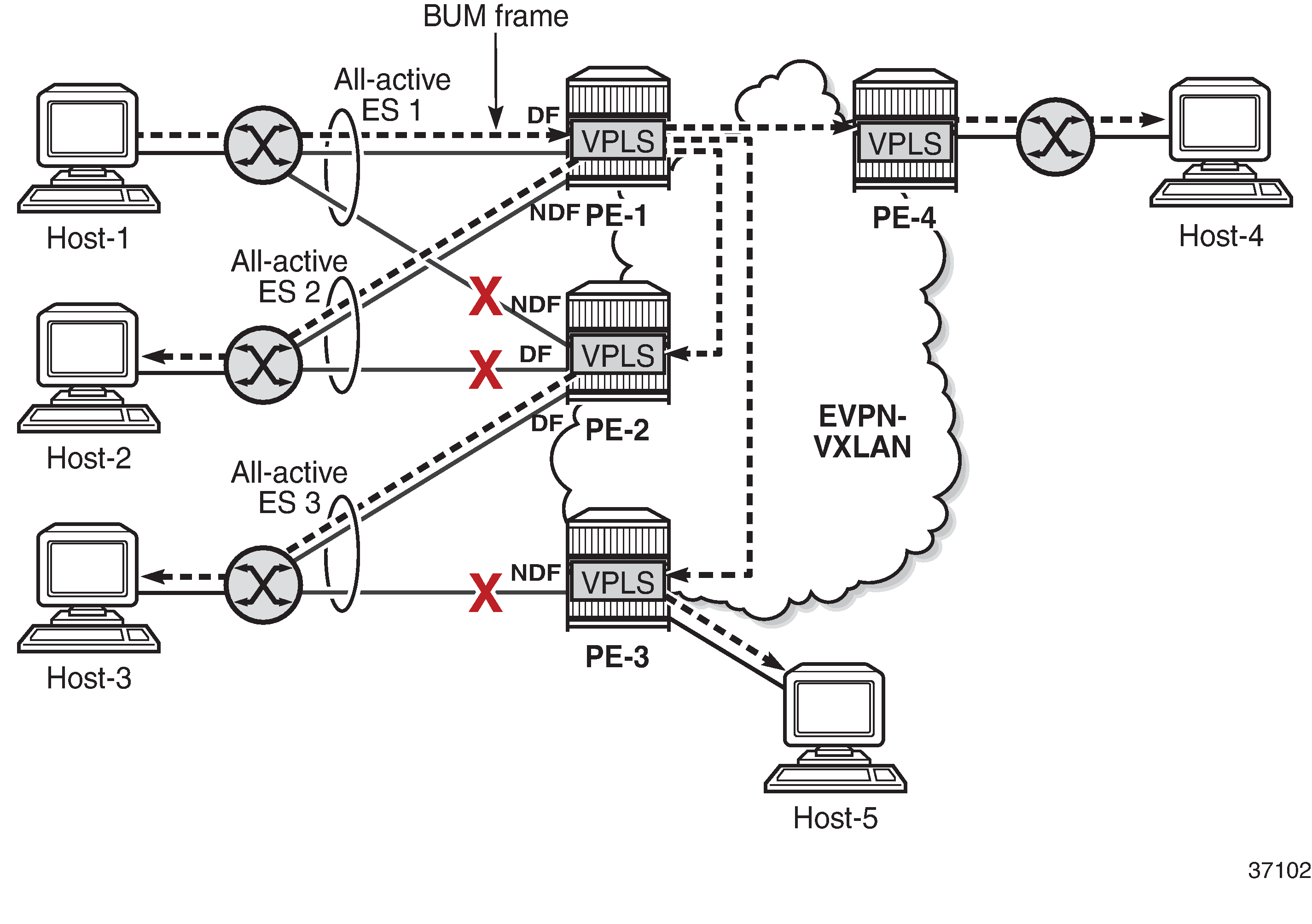
In this example, BUM frames sent by Host-1 are treated as follows.
Ingress node PE-1 receives BUM frames from Host-1 and forwards them to the other PEs (EVPN-VXLAN destinations) and the local all-active ES SAP toward Host-2, even though the SAP is in NDF state.
Egress node PE-2 receives BUM frames on VXLAN. PE-2 identifies the source VTEP as a PE with which two all-active ESs are shared, so it does not forward the BUM frames to the two shared ESs. PE-2 forwards the BUM frames to the non-shared ES toward Host-3 because it is in DF state.
Egress node PE-3 receives BUM traffic from PE-1, with which it does not share any ESs, so it forwards the BUM frames based on normal rules: it does not forward them toward Host-3, because the ES SAP is in NDF state. PE-3 only forwards toward Host-5.
PE-4 does not share any ESs with PE-1, so the normal rules apply. PE-4 forwards the BUM frames toward Host-4.
Known limitations for local bias
In VXLAN, there are no BUM labels or any tunnel indication that can identify BUM traffic. The egress PE must solely rely on the Customer MAC (CMAC) destination address and this may create transient issues.
Duplicate unicast traffic may occur when the CMAC destination address MAC1 is unknown on the ingress PE-3, while known on the egress PEs (PE-1 and PE-2). Duplicate unicast packets when MAC1 is unknown on PE-3 only shows that a packet with destination MAC1 arrives at PE-3, where it is flooded via ingress replication to PE-1 and PE-2, where MAC1 is known. PE-1 and PE-2 both forward the packets with CMAC destination MAC1 to CE-1, so multiple copies are sent to CE-1.
Figure 2. Duplicate unicast packets when MAC1 is unknown on PE-3 only 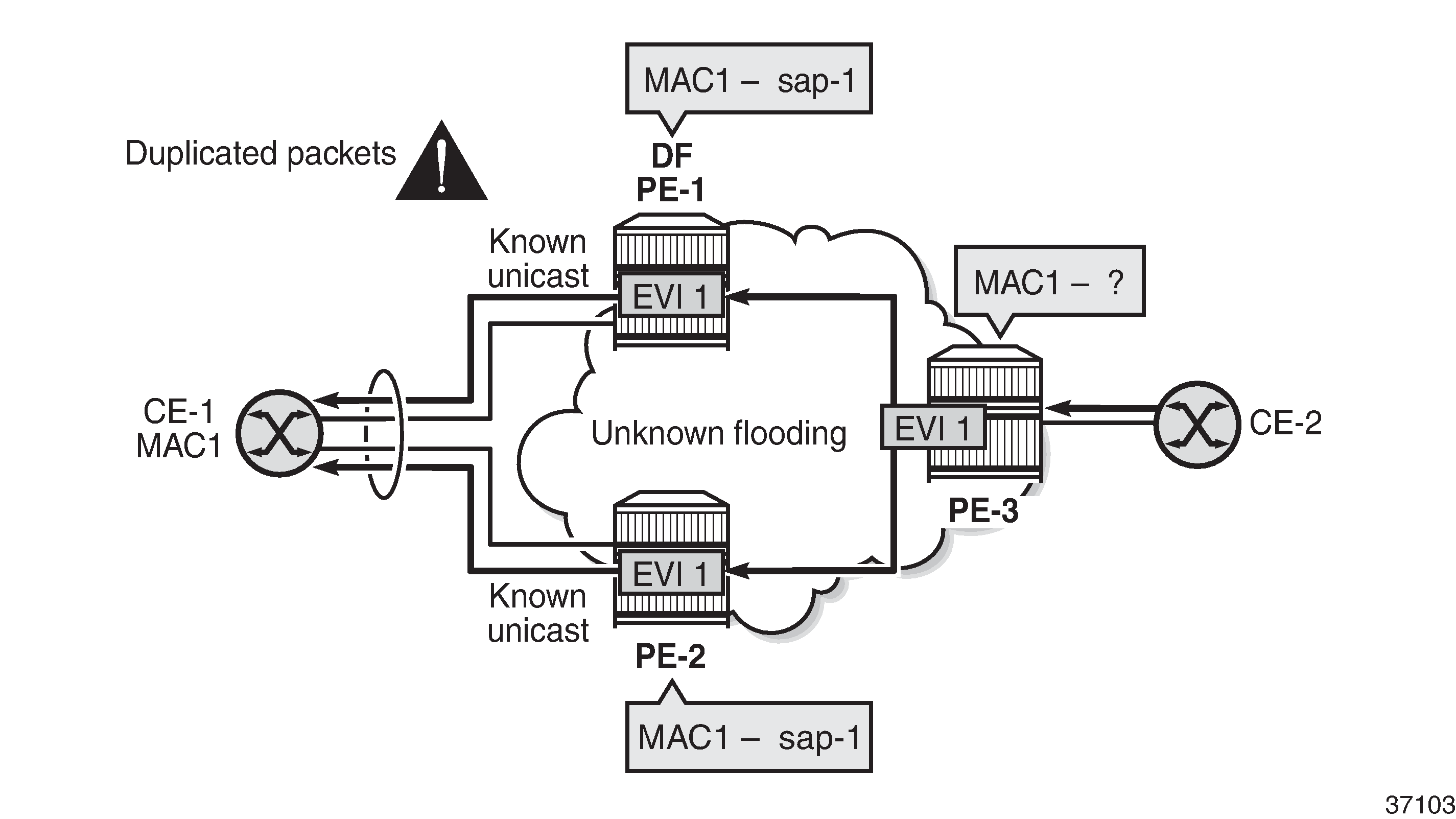
A blackhole may occur when the CMAC destination address MAC1 is known on PE-3, but unknown on PE-1 and PE-2 and the aliasing hashing on PE-3 picks up the path to the NDF, where unknown unicast traffic is dropped, as shown in Packet blackhole for traffic on NDF PE-2 when MAC1 is known on PE-3 only. When the path to the DF is picked, no problem occurs, because the DF forwards BUM traffic.
Figure 3. Packet blackhole for traffic on NDF PE-2 when MAC1 is known on PE-3 only 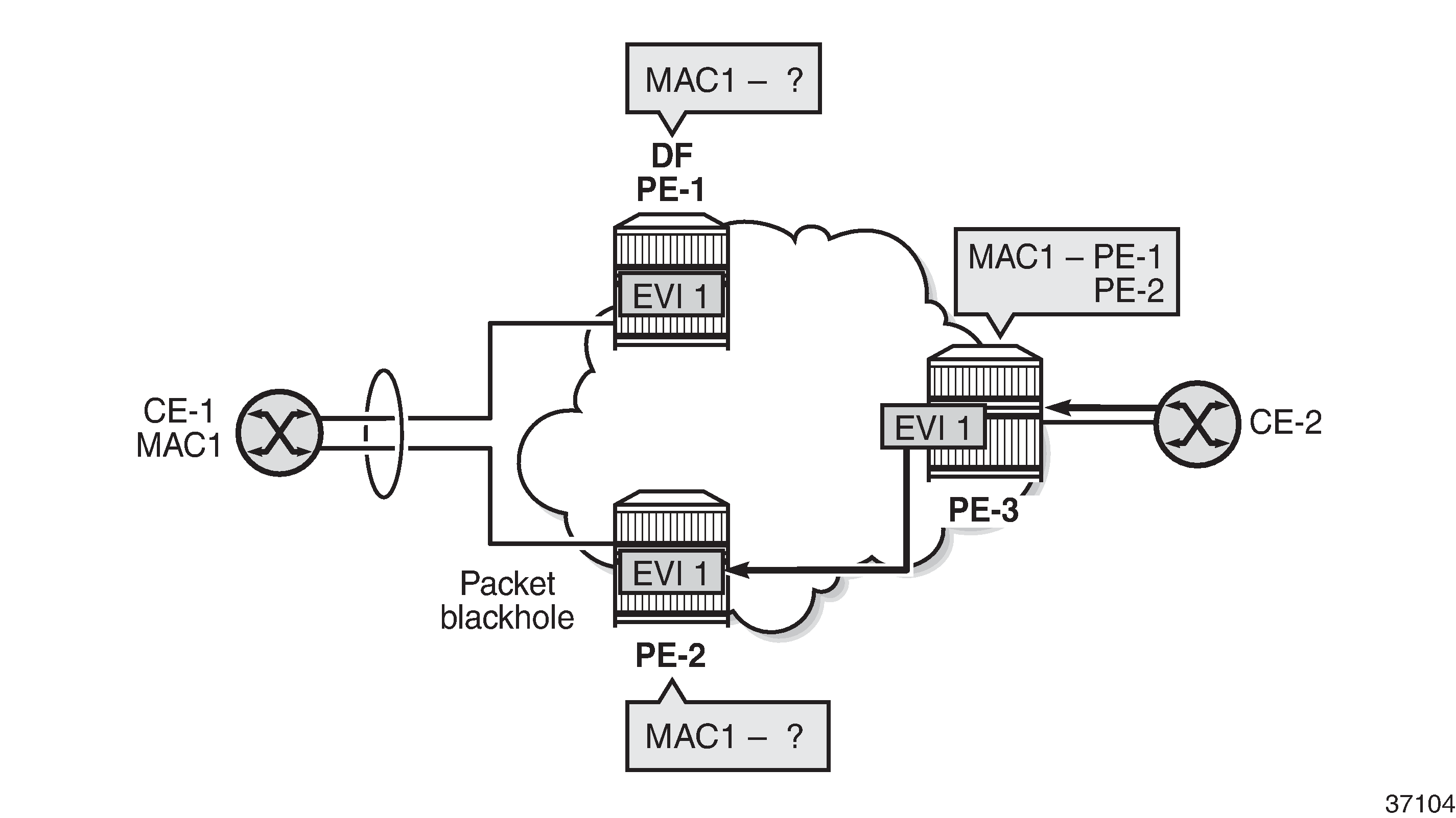
A blackhole can be created when a remote SAP is disabled (shutdown), as shown in Blackhole created when a remote SAP is disabled.
Under normal circumstances, when CE-3 sends BUM traffic to ingress node PE-3, the local bias mechanism on PE-3 forwards the BUM packets to SAP3, even though it is NDF for the ES. The BUM traffic is also flooded to PE-2, where it is forwarded to CE-2, but not to SAP2, because the ES is shared with PE-3.
When SAP3 is manually disabled, PE-3 withdraws the AD per-EVI route corresponding to SAP3. This does not change the local bias filtering for SAP2 on PE-2, so when CE-3 sends BUM traffic, it can neither be forwarded to CE-23 via SAP3 nor by PE-2.
Figure 4. Blackhole created when a remote SAP is disabled 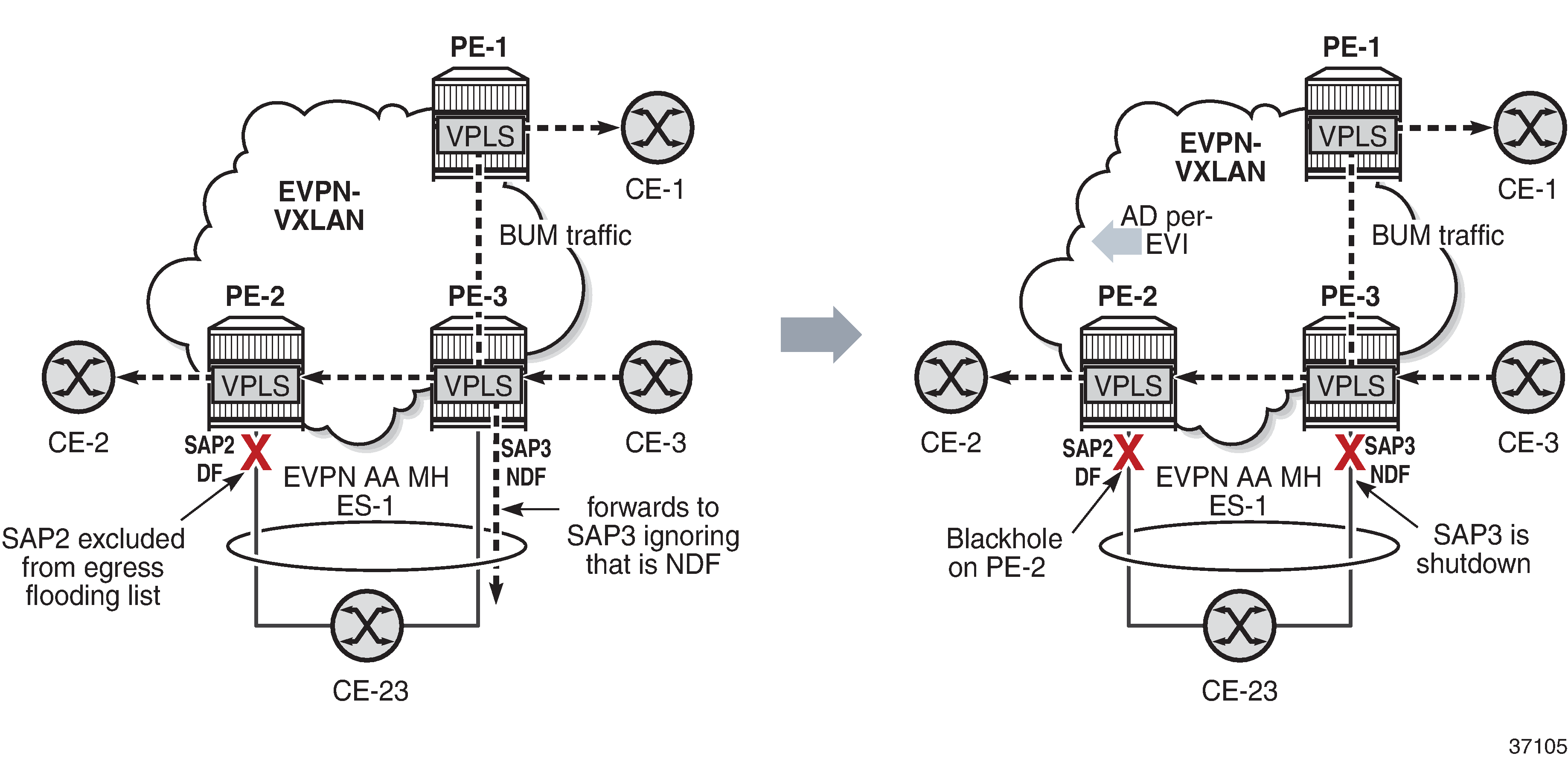
CLI
The multi-homing capabilities are enabled in all the PEs attached to the VPLS service by configuring the options auto-disc-route-advertisement and mh-mode network in the vpls bgp-evpn vxlan context.
The auto-disc-route-advertisement option is by default disabled, but it can be enabled as follows:
*A:PE-2>config>service>vpls>bgp-evpn>vxlan$ auto-disc-route-advertisement
This auto-disc-route-advertisement command is only configurable for EVPN-VXLAN VPLS services and is implicitly enabled on all instances where it is not configurable. Auto-disc-route-advertisement is required in nodes with local ESs and remote ESs to process and enable the creation of ES destinations.
When auto-disc-route-advertisement is enabled, BGP-EVPN:
processes Auto-Discovery per EVPN instance (AD per-EVI) routes and AD per-ES routes
processes MAC/IP routes with non-zero Ethernet Segment Identifier (ESI) — without resetting the ESI to zero
creates ES destinations upon receiving MAC/IP routes and AD per-ES/EVI routes with non-zero ESI
The mh-mode option can be configured with the values access or network. For EVPN-VXLAN services, the default value is access. The following command configures mh-mode network:
*A:PE-2>config>service>vpls>bgp-evpn>vxlan$ mh-mode network
When mh-mode network is configured, BGP-EVPN:
activates multi-homing for the local ES SAPs or SDP-bindings and creates ES associations and related processes, such as:
the local bias mode allowing the system to add all-active SAPs to the flooding list regardless of the DF state
the source VTEP lookup mode
runs DF election for the ESs associated to the service
triggers the advertisement of AD per-ES routes, AD per-EVI routes, and non-zero MAC/IP routes for the ESs in the service
Configuration
The following examples are configured:
EVPN-VXLAN multi-homing with system IPv4 VTEP addresses
Example topology shows the topology with three all-active multi-homing ESs and one single-active multi-homing ES. This example shows the configuration for virtual Ethernet Segments, as described in the Virtual Ethernet Segments chapter, but non-virtual ES can also be used.
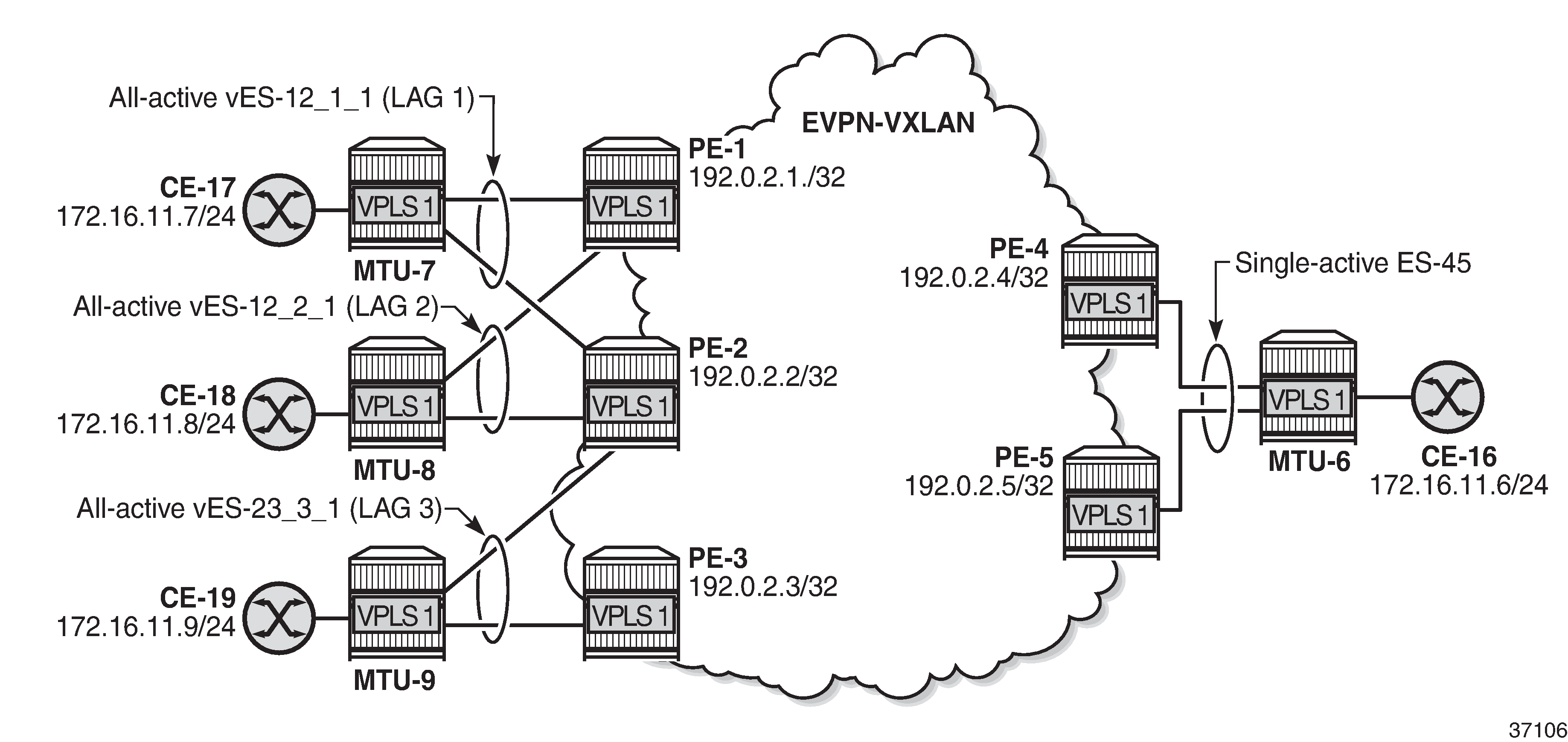
The initial configuration on the PEs includes:
cards, MDAs, ports
LAG 1 on MTU-7, PE-1, PE-2
LAG 2 on MTU-8, PE-1, PE-2
LAG 3 on MTU-9, PE-2, PE-3
router interfaces
IS-IS between the PEs
SR-ISIS between PE-4 and MTU-6 and between PE-5 and MTU-6 (and TLDP for SDP signaling)
BGP is configured between the PEs for the EVPN address family. PE-1 acts as route reflector, as follows:
# on RR PE-1:
configure
    router Base
        autonomous-system 64500
        bgp
            vpn-apply-import
            vpn-apply-export
            enable-peer-tracking
            rapid-withdrawal
            rapid-update evpn
            group "internal"
                family evpn
                cluster 192.0.2.1
                peer-as 64500
                neighbor 192.0.2.2
                exit
                neighbor 192.0.2.3
                exit
                neighbor 192.0.2.4
                exit
                neighbor 192.0.2.5
                exit
            exit
        exit
ES configuration
The all-active ESs "vES-12_1_1" and "vES-12_2_1" are configured on PE-1 and PE-2. The configuration on PE-1 is as follows. The configuration on PE-2 is similar, but with different preference values.
# on PE-1:
configure
    service
        system
            bgp-evpn
                ethernet-segment "vES-12_1_1" virtual create
                    esi 00:12:12:12:12:12:12:00:01:01
                    service-carving
                        mode manual
                        manual
                            preference create
                                value 100            # on PE-2: preference value 150
                            exit
                            evi 1
                        exit
                    exit
                    multi-homing all-active
                    lag 1
                    dot1q
                        q-tag-range 1
                    exit
                    no shutdown
                exit
                ethernet-segment "vES-12_2_1" virtual create
                    esi 00:12:12:12:12:12:12:00:02:01
                    service-carving
                        mode manual
                        manual
                            preference create
                                value 150            # on PE-2: preference value 100
                            exit
                            evi 1
                        exit
                    exit
                    multi-homing all-active
                    lag 2
                    dot1q
                        q-tag-range 1
                    exit
                    no shutdown
                exit
            exit
        exit
On PE-2 and PE-3, the all-active ES "vES-23_3_1" is configured in a similar way:
# on PE-2:
configure
    service
        system
            bgp-evpn
                ethernet-segment "vES-23_3_1" virtual create
                    esi 00:23:23:23:23:23:23:00:03:01
                    service-carving
                        mode manual
                        manual
                            preference create
                                value 100            # on PE-3: preference value 150
                            exit
                            evi 1
                        exit
                    exit
                    multi-homing all-active
                    lag 3
                    dot1q
                        q-tag-range 1
                    exit
                    no shutdown
                exit
On PE-4 and PE-5, the single-active ES "ES-45" is configured, as follows:
# on PE-4:
configure
    service
        sdp 46 mpls create                           # on PE-5: sdp 56
            far-end 192.0.2.6
            sr-isis
            keep-alive
                shutdown
            exit
            no shutdown
        exit
        system
            bgp-evpn
                ethernet-segment "ES-45" create
                    esi 00:45:45:45:45:45:45:00:00:01
                    service-carving
                        mode manual
                        manual
                            preference create
                                value 100            # on PE-5: preference value 150
                            exit
                            evi 1
                        exit
                    exit
                    multi-homing single-active
                    sdp 46                           # on PE-5: sdp 56
                    no shutdown
                exit
            exit
        exit
VPLS configuration
VPLS 1 is configured on PE-2 as follows. The configuration is similar on PE-1 and PE-3.
# on PE-2:
configure
    service
        system
            bgp-auto-rd-range 192.0.2.2 comm-val 1 to 1000   # different values on PEs
        exit
        vpls 1 name "VPLS 1" customer 1 create
            vxlan instance 1 vni 1 create
            exit
            bgp
                route-distinguisher auto-rd
                route-target export target:64500:1 import target:64500:1
            exit
            bgp-evpn
                evi 1
                vxlan bgp 1 vxlan-instance 1
                    ecmp 2
                    auto-disc-route-advertisement
                    mh-mode network
                    no shutdown
                exit
            exit
            stp
                shutdown
            exit
            sap lag-1:1 create                       # LAG 1 also on PE-1, not on PE-3
                no shutdown
            exit
            sap lag-2:1 create                       # LAG 2 also on PE-1, not on PE-3
                no shutdown
            exit
            sap lag-3:1 create                       # LAG 3 also on PE-3, not on PE-1
                no shutdown
            exit
            no shutdown
        exit
The EVPN-VXLAN multi-homing capabilities are enabled in the PEs attached to VPLS 1 by the commands auto-disc-route-advertisement and mh-mode network. The auto-disc-route-advertisement command enables the advertisement and processing of multi-homing routes, and the mh-mode network command activates the DF election procedures.
ECMP is required for per-flow load balancing for VXLAN ES destinations with two or more next hops. In this example, ECMP is configured with a value of 2.
On PE-4, VPLS 1 is configured as follows. The configuration on PE-5 is similar.
# on PE-4:
configure
    service
        vpls 1 name "VPLS 1" customer 1 create
            vxlan instance 1 vni 1 create
            exit
            bgp
                route-distinguisher auto-rd
                route-target export target:64500:1 import target:64500:1
            exit
            bgp-evpn
                evi 1
                vxlan bgp 1 vxlan-instance 1
                    ecmp 2
                    auto-disc-route-advertisement
                    mh-mode network
                    no shutdown
                exit
            exit
            spoke-sdp 46:1 create                    # on PE-5: spoke-sdp 56:1
            exit
            no shutdown
        exit
Show commands
The following command shows that the commands mh-mode network and auto-disc-route-advertisement are enabled:
*A:PE-2# show service id 1 bgp-evpn

===============================================================================
BGP EVPN Table
===============================================================================
MAC Advertisement  : Enabled            Unknown MAC Route  : Disabled
CFM MAC Advertise  : Disabled
Creation Origin    : manual
MAC Dup Detn Moves : 5                  MAC Dup Detn Window: 3
MAC Dup Detn Retry : 9                  Number of Dup MACs : 0
MAC Dup Detn BH    : Disabled
IP Route Advert    : Disabled
Sel Mcast Advert   : Disabled

EVI                : 1
Ing Rep Inc McastAd: Enabled
Accept IVPLS Flush : Disabled

-------------------------------------------------------------------------------
Detected Duplicate MAC Addresses             Time Detected
-------------------------------------------------------------------------------
-------------------------------------------------------------------------------
===============================================================================

===============================================================================
BGP EVPN VXLAN Information
===============================================================================
Admin Status       : Enabled            Bgp Instance       : 1
Vxlan Instance     : 1
Max Ecmp Routes    : 2
Default Route Tag  : none
Send EVPN Encap    : Enabled
Imet-Ir routes     : Enabled
MH Mode            : network
Auto Disc Route Adv: Enabled
Oper Group         :
===============================================================================
The following command shows that PE-1 is DF for the all-active ES vES-12_1_1 and NDF for the all-active ES vES-12_2_1:
*A:PE-1# show service id 1 ethernet-segment

===============================================================================
SAP Ethernet-Segment Information
===============================================================================
SAP                   Eth-Seg                          Status
-------------------------------------------------------------------------------
lag-1:1               vES-12_1_1                       DF
lag-2:1               vES-12_2_1                       NDF
===============================================================================
No sdp entries
No vxlan instance entries
The following command shows that PE-2 is NDF for the all-active ES vES-12_1_1 and DF for the other two all-active ESs:
*A:PE-2# show service id 1 ethernet-segment

===============================================================================
SAP Ethernet-Segment Information
===============================================================================
SAP                   Eth-Seg                          Status
-------------------------------------------------------------------------------
lag-1:1               vES-12_1_1                       NDF
lag-2:1               vES-12_2_1                       DF
lag-3:1               vES-23_3_1                       DF
===============================================================================
No sdp entries
No vxlan instance entries
PE-3 is NDF for the all-active multi-homing ES vES-23_3_1:
*A:PE-3# show service id 1 ethernet-segment

===============================================================================
SAP Ethernet-Segment Information
===============================================================================
SAP                   Eth-Seg                          Status
-------------------------------------------------------------------------------
lag-3:1               vES-23_3_1                       NDF
===============================================================================
No sdp entries
No vxlan instance entries
PE-4 is DF for the single-active multi-homing ES ES-45:
*A:PE-4# show service id 1 ethernet-segment
No sap entries

===============================================================================
SDP Ethernet-Segment Information
===============================================================================
SDP                   Eth-Seg                          Status
-------------------------------------------------------------------------------
46:1                  ES-45                            DF
===============================================================================
No vxlan instance entries
PE-5 is NDF for the single-active multi-homing ES ES-45:
*A:PE-5# show service id 1 ethernet-segment
No sap entries

===============================================================================
SDP Ethernet-Segment Information
===============================================================================
SDP                   Eth-Seg                          Status
-------------------------------------------------------------------------------
56:1                  ES-45                            NDF
===============================================================================
No vxlan instance entries
The following command shows the VXLAN destinations for VPLS 1 on PE-3; the system addresses of the other PEs act as destination VTEP addresses.
*A:PE-3# show service id 1 vxlan destinations

===============================================================================
Egress VTEP, VNI
===============================================================================
Instance    VTEP Address                            Egress VNI  EvpnStatic Num
 Mcast       Oper State                              L2 PBR     SupBcasDom MACs
-------------------------------------------------------------------------------
1           192.0.2.1                               1           evpn       0
 BUM         Up                                      No          No
1           192.0.2.2                               1           evpn       0
 BUM         Up                                      No          No
1           192.0.2.4                               1           evpn       0
 BUM         Up                                      No          No
1           192.0.2.5                               1           evpn       0
 BUM         Up                                      No          No
-------------------------------------------------------------------------------
Number of Egress VTEP, VNI : 4
-------------------------------------------------------------------------------
===============================================================================

===============================================================================
BGP EVPN-VXLAN Ethernet Segment Dest
===============================================================================
Instance  Eth SegId                       Num. Macs     Last Change
-------------------------------------------------------------------------------
1         00:12:12:12:12:12:12:00:01:01   1             08/26/2021 07:17:08
1         00:12:12:12:12:12:12:00:02:01   1             08/26/2021 07:17:18
1         00:45:45:45:45:45:45:00:00:01   1             08/26/2021 07:17:19
-------------------------------------------------------------------------------
Number of entries: 3
-------------------------------------------------------------------------------
===============================================================================
The following command on PE-3 shows the EVPN-VXLAN destination next hops (192.0.2.1 and 192.0.2.2) for alias ESI 00:12:12:12:12:12:12:00:01:01. The VTEP addresses 192.0.2.1 and 192.0.2.2 are the system addresses of PE-1 and PE-2.
*A:PE-3# show service id 1 vxlan esi 00:12:12:12:12:12:12:00:01:01

===============================================================================
BGP EVPN-VXLAN Ethernet Segment Dest
===============================================================================
Instance  Eth SegId                       Num. Macs     Last Change
-------------------------------------------------------------------------------
1         00:12:12:12:12:12:12:00:01:01   1             08/26/2021 07:17:18
-------------------------------------------------------------------------------
Number of entries: 1
-------------------------------------------------------------------------------
===============================================================================

===============================================================================
BGP EVPN-VXLAN Dest TEP Info
===============================================================================
Instance  TEP Address                   Egr VNI             Last Change
-------------------------------------------------------------------------------
1         192.0.2.1                     1                   08/26/2021 07:17:18
1         192.0.2.2                     1                   08/26/2021 07:17:18
-------------------------------------------------------------------------------
Number of entries : 2
-------------------------------------------------------------------------------
===============================================================================
Tools command to check local bias
The following tools command on PE-2 checks whether local bias is enabled for the peers in ES "vES-12_1_1". The output lists the PEs that are in the candidate DF election list for the ES and whether local bias procedures are enabled on them. In this case, only peer 192.0.2.1 is in the list and local bias is enabled. The output is similar for ES "vES-12_2_1".
*A:PE-2# tools dump service system bgp-evpn ethernet-segment "vES-12_1_1" local-bias
-------------------------------------------------------------------------------
[08/26/2021 07:20:48] Vxlan Local Bias Information
----------------------------------------------------------------------+--------
Peer                                                                  | Enabled
----------------------------------------------------------------------+--------
192.0.2.1                                                             | Yes
-------------------------------------------------------------------------------
The PE can only enable local bias procedures on a maximum of three PEs that are attached to the same ES and use multi-homed VXLAN services. If more than three PEs exist, the PEs are ordered by preference or IP address and only the top three PEs are considered for local bias. The order is as follows:
lowest IP address (automatic service-carving)
lowest preference (manual service-carving with configured EVI)
highest preference (manual service-carving without configured EVI)
The following tools command on PE-2 shows that local bias is enabled for peer 192.0.2.3 in ES "vES-23_3_1":
*A:PE-2# tools dump service system bgp-evpn ethernet-segment "vES-23_3_1" local-bias
-------------------------------------------------------------------------------
[08/26/2021 07:20:48] Vxlan Local Bias Information
----------------------------------------------------------------------+--------
Peer                                                                  | Enabled
----------------------------------------------------------------------+--------
192.0.2.3                                                             | Yes
-------------------------------------------------------------------------------
Verify local bias for BUM traffic in all-active multi-homing ESs
Unknown unicast traffic is generated on MTU-7. This traffic is received in ingress queue 11 for SAP lag-1:1 on ingress node PE-1, as follows:
*A:PE-1# monitor service id 1 sap lag-1:1

===============================================================================
Monitor statistics for Service 1 SAP lag-1:1
===============================================================================
---snip---
-------------------------------------------------------------------------------
Sap per Queue Stats
-------------------------------------------------------------------------------
                        Packets                 Octets

Ingress Queue 1 (Unicast) (Priority)
Off. HiPrio           : 0                       0
Off. LowPrio          : 0                       0
Dro. HiPrio           : 0                       0
Dro. LowPrio          : 0                       0
For. InProf           : 0                       0
For. OutProf          : 0                       0

Ingress Queue 11 (Multipoint) (Priority)
Off. Combined         : 6                       408
Off. Managed          : 0                       0
Dro. HiPrio           : 0                       0
Dro. LowPrio          : 0                       0
For. InProf           : 0                       0
For. OutProf          : 6                       408

Egress Queue 1
For. In/InplusProf    : 0                       0
For. Out/ExcProf      : 0                       0
Dro. In/InplusProf    : 0                       0
Dro. Out/ExcProf      : 0                       0

===============================================================================
On the ingress node PE-1, the local bias mechanism forwards this BUM traffic toward EVPN-VXLAN destinations, and also to the local SAPs of all-active ESs, regardless of the DF state. In this case, the local bias mechanism forwards the BUM traffic to lag-2:1 toward MTU-8, even though PE-1 is NDF in ES "vES-12_2_1".
*A:PE-1# monitor service id 1 sap lag-2:1

===============================================================================
Monitor statistics for Service 1 SAP lag-2:1
===============================================================================
-------------------------------------------------------------------------------
---snip---
-------------------------------------------------------------------------------
Sap Statistics
-------------------------------------------------------------------------------
Last Cleared Time     : N/A

                        Packets                 Octets
CPM Ingress           : 0                       0
Forwarding Engine Stats
Dropped               : 0                       0
Received Valid        : 0                       0
Off. HiPrio           : 0                       0
Off. LowPrio          : 0                       0
Off. Uncolor          : 0                       0
Off. Managed          : 0                       0

Queueing Stats(Ingress QoS Policy 1)
Dro. HiPrio           : 0                       0
Dro. LowPrio          : 0                       0
For. InProf           : 0                       0
For. OutProf          : 0                       0

Queueing Stats(Egress QoS Policy 1)
Dro. In/InplusProf    : 0                       0
Dro. Out/ExcProf      : 0                       0
For. In/InplusProf    : 0                       0
For. Out/ExcProf      : 6                       408
-------------------------------------------------------------------------------
The egress PEs PE-2 and PE-3 receive the BUM traffic on the EVPN-VXLAN terminations. On egress PEs, the local bias mechanism filters BUM traffic based on the source IP address 192.0.2.1 of PE-1. PE-2 does not forward the traffic to the local SAPs lag-1:1 and lag-2:1, because PE-2 shares the all-active ESs "vES-12_1_1" and "vES-12_2_1" with PE-1. However, PE-2 forwards the BUM traffic to the non-shared ES "vES-23_3_1" because it is DF.
The following monitor commands show that PE-2 does not send any traffic toward SAP lag-1:1 or SAP lag-2:1.
*A:PE-2# monitor service id 1 sap lag-1:1
---snip---

Queueing Stats(Egress QoS Policy 1)
Dro. In/InplusProf    : 0                       0
Dro. Out/ExcProf      : 0                       0
For. In/InplusProf    : 0                       0
For. Out/ExcProf      : 0                       0
---snip---
*A:PE-2# monitor service id 1 sap lag-2:1
---snip---

Queueing Stats(Egress QoS Policy 1)
Dro. In/InplusProf    : 0                       0
Dro. Out/ExcProf      : 0                       0
For. In/InplusProf    : 0                       0
For. Out/ExcProf      : 0                       0
---snip---
The following monitor command shows that PE-2 forwards the traffic to SAP lag-3:1 toward MTU-9:
*A:PE-2# monitor service id 1 sap lag-3:1
---snip---

Queueing Stats(Egress QoS Policy 1)
Dro. In/InplusProf    : 0                       0
Dro. Out/ExcProf      : 0                       0
For. In/InplusProf    : 0                       0
For. Out/ExcProf      : 6                       408
---snip---
Egress node PE-3 receives BUM traffic on VXLAN and filters on IP address 192.0.2.1, but there are no shared ESs with PE-1. PE-3 is NDF for the non-shared ES vES-23_3_1, so it does not forward the traffic to SAP lag-3:1, as follows:
*A:PE-3# monitor service id 1 sap lag-3:1
---snip---

Queueing Stats(Egress QoS Policy 1)
Dro. In/InplusProf    : 0                       0
Dro. Out/ExcProf      : 0                       0
For. In/InplusProf    : 0                       0
For. Out/ExcProf      : 0                       0
---snip---
EVPN-VXLAN multi-homing with non-system IPv4 VTEP addresses
Non-system IPv4 VTEP multi-homing for VXLAN VPLS 2 shows the non-system IPv4 addresses to be used as VTEP addresses.
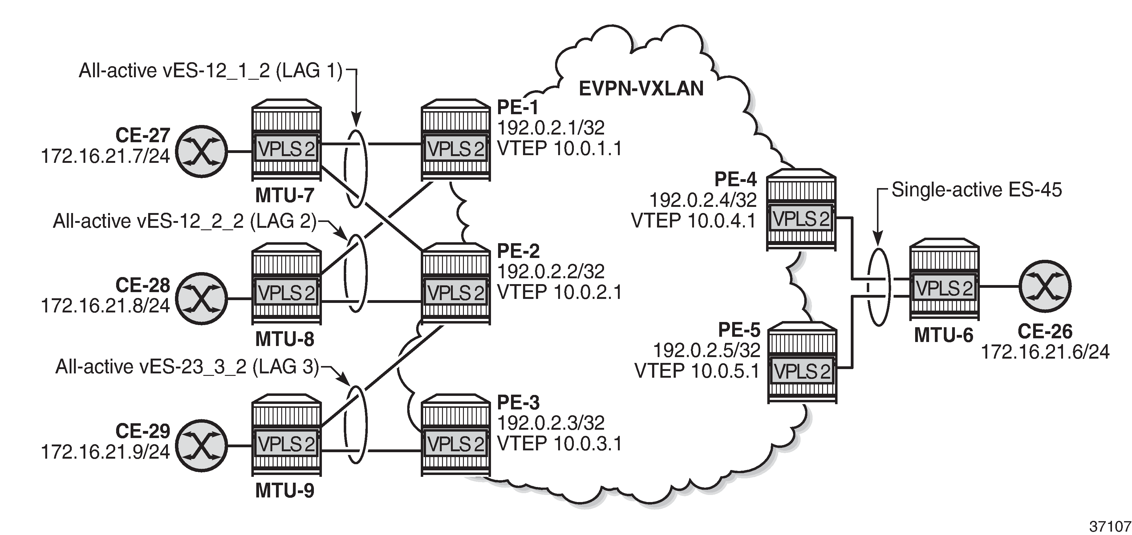
Forwarding Path Extension (FPE), as described in the VXLAN Forwarding Path Extension chapter, is configured on all PEs. The configuration on PE-1 is as follows:
# on PE-1:
configure
    port-xc
        pxc 1 create
            port 1/2/6
            no shutdown
        exit
    exit
    port pxc-1.a
        ethernet
            encap-type dot1q
        exit
        no shutdown
    exit
    port pxc-1.b
        ethernet
            encap-type dot1q
        exit
        no shutdown
    exit
    port 1/2/6
        no shutdown
    exit
    fwd-path-ext
        sdp-id-range from 10000 to 10127
        fpe 1 create
            path pxc 1
            vxlan-termination
        exit
    exit
    router Base
        interface "loopback1"
            address 10.0.1.0/31
            loopback
            ipv6
                address 2001:db8::10:0/127
            exit
            no shutdown
        exit
        isis 0
            interface "loopback1"
                passive
                no shutdown
            exit
        exit
    exit
    service
        system
            vxlan
                tunnel-termination 10.0.1.1 fpe 1 create
                tunnel-termination 2001:db8::10:1 fpe 1 create
            exit
        exit
    exit
The configuration on the other PEs is similar but with different IP addresses, for example, 10.0.2.1 on PE-2, 10.0.3.1 on PE-3, and so on.
The non-system IP address in each of the PEs in the ES must match in the following three commands for the local PE to be considered suitable for DF election:
es-orig-ip 10.0.x.1 (ES)
The es-orig-ip command modifies the originating IP address in the ES routes advertised for the ES and makes the system use this IP address when adding the local PE as DF candidate.
route-next-hop 10.0.x.1 (ES)
The route-next-hop command changes the next hop of the ES routes and AD per-ES routes to the configured address.
vxlan-src-vtep 10.0.x.1 (VPLS)
The vxlan-src-vtep command makes the router use the configured IP address as the VXLAN tunnel source IP address (source VTEP) for originating VXLAN-encapsulated frames for the service. The source VTEP is also used to set the BGP NLRI next hop in EVPN route advertisements for the services.
The following all-active multi-homing ESs are configured on PE-2 with non-system IPv4 address 10.0.2.1:
# on PE-2:
configure
    service
        system
            bgp-evpn
                ethernet-segment "vES-12_1_2" virtual create
                    esi 00:12:12:12:12:12:12:00:01:02
                    es-orig-ip 10.0.2.1
                    route-next-hop 10.0.2.1
                    service-carving
                        mode manual
                        manual
                            preference create
                                value 150
                            exit
                        exit
                    exit
                    multi-homing all-active
                    lag 1
                    dot1q
                        q-tag-range 2
                    exit
                    no shutdown
                exit
                ethernet-segment "vES-12_2_2" virtual create
                    esi 00:12:12:12:12:12:12:00:02:02
                    es-orig-ip 10.0.2.1
                    route-next-hop 10.0.2.1
                    service-carving
                        mode manual
                        manual
                            preference create
                                value 100
                            exit
                        exit
                    exit
                    multi-homing all-active
                    lag 2
                    dot1q
                        q-tag-range 2
                    exit
                    no shutdown
                exit
                ethernet-segment "vES-23_3_2" virtual create
                    esi 00:23:23:23:23:23:23:00:03:02
                    es-orig-ip 10.0.2.1
                    route-next-hop 10.0.2.1
                    service-carving
                        mode manual
                        manual
                            preference create
                                value 100
                            exit
                        exit
                    exit
                    multi-homing all-active
                    lag 3
                    dot1q
                        q-tag-range 2
                    exit
                    no shutdown
                exit
            exit
        exit
The ES configuration on the other PEs is similar, but with different IP addresses and preference values.
VPLS 2 is configured with source VTEP 10.0.2.1 on PE-2:
# on PE-2:
configure
    service
        vpls 2 name "VPLS 2" customer 1 create
            vxlan-src-vtep 10.0.2.1                  # different IP address on different PEs
            vxlan instance 1 vni 2 create
            exit
            bgp
                route-distinguisher auto-rd
                route-target export target:64500:2 import target:64500:2
            exit
            bgp-evpn
                evi 2
                vxlan bgp 1 vxlan-instance 1
                    ecmp 2
                    auto-disc-route-advertisement
                    mh-mode network
                    no shutdown
                exit
            exit
            stp
                shutdown
            exit
            sap lag-1:2 create                       # lag-1 is shared with PE-1
                no shutdown
            exit
            sap lag-2:2 create                       # lag-2 is shared with PE-1
                no shutdown
            exit
            sap lag-3:2 create                       # lag-3 is shared with PE-3
                no shutdown
            exit
            no shutdown
        exit
The configuration on the other PEs is similar.
Verification
The following command shows the DF status for the different ESs in VPLS 2 on PE-1:
*A:PE-1# show service id 2 ethernet-segment

===============================================================================
SAP Ethernet-Segment Information
===============================================================================
SAP                   Eth-Seg                          Status
-------------------------------------------------------------------------------
lag-1:2               vES-12_1_2                       NDF
lag-2:2               vES-12_2_2                       DF
===============================================================================
No sdp entries
No vxlan instance entries
The following command on PE-1 shows that the source VTEP for VPLS 2 is 10.0.1.1:
*A:PE-1# show service id 2 vxlan
===============================================================================
VPLS VXLAN
===============================================================================
Vxlan Src Vtep IP: 10.0.1.1

===============================================================================
Vxlan Instance
===============================================================================
VXLAN Instance                VNI         AR          Oper-flags   VTEP
                                                                   security
-------------------------------------------------------------------------------
1                             2           none        none         disabled
-------------------------------------------------------------------------------
Number of Entries : 1
-------------------------------------------------------------------------------
===============================================================================
The following command on PE-1 shows the (non-system) VXLAN destinations for VPLS 2:
*A:PE-1# show service id 2 vxlan destinations

===============================================================================
Egress VTEP, VNI
===============================================================================
Instance    VTEP Address                            Egress VNI  EvpnStatic Num
 Mcast       Oper State                              L2 PBR     SupBcasDom MACs
-------------------------------------------------------------------------------
1           10.0.2.1                                2           evpn       0
 BUM         Up                                      No          No
1           10.0.3.1                                2           evpn       0
 BUM         Up                                      No          No
1           10.0.4.1                                2           evpn       0
 BUM         Up                                      No          No
1           10.0.5.1                                2           evpn       0
 BUM         Up                                      No          No
-------------------------------------------------------------------------------
Number of Egress VTEP, VNI : 4
-------------------------------------------------------------------------------
===============================================================================

===============================================================================
BGP EVPN-VXLAN Ethernet Segment Dest
===============================================================================
Instance  Eth SegId                       Num. Macs     Last Change
-------------------------------------------------------------------------------
1         00:23:23:23:23:23:23:00:03:02   1             08/26/2021 07:35:03
1         00:45:45:45:45:45:45:00:00:02   1             08/26/2021 07:34:38
-------------------------------------------------------------------------------
Number of entries: 2
-------------------------------------------------------------------------------
===============================================================================
The non-system VTEP addresses in the all-active multi-homing ES with ESI 00:23:23:23:23:23:23:00:03:02 are 10.0.2.1 and 10.0.3.1, as follows:
*A:PE-1# show service id 2 vxlan esi 00:23:23:23:23:23:23:00:03:02

===============================================================================
BGP EVPN-VXLAN Ethernet Segment Dest
===============================================================================
Instance  Eth SegId                       Num. Macs     Last Change
-------------------------------------------------------------------------------
1         00:23:23:23:23:23:23:00:03:02   1             08/26/2021 07:35:03
-------------------------------------------------------------------------------
Number of entries: 1
-------------------------------------------------------------------------------
===============================================================================

===============================================================================
BGP EVPN-VXLAN Dest TEP Info
===============================================================================
Instance  TEP Address                   Egr VNI             Last Change
-------------------------------------------------------------------------------
1         10.0.2.1                      2                   08/26/2021 07:35:03
1         10.0.3.1                      2                   08/26/2021 07:35:03
-------------------------------------------------------------------------------
Number of entries : 2
-------------------------------------------------------------------------------
===============================================================================
EVPN-VXLAN multi-homing with non-system IPv6 VTEP addresses
Non-system IPv6 VTEP multi-homing for VXLAN VPLS 2 shows the non-system IPv6 addresses to be used as VTEP addresses.
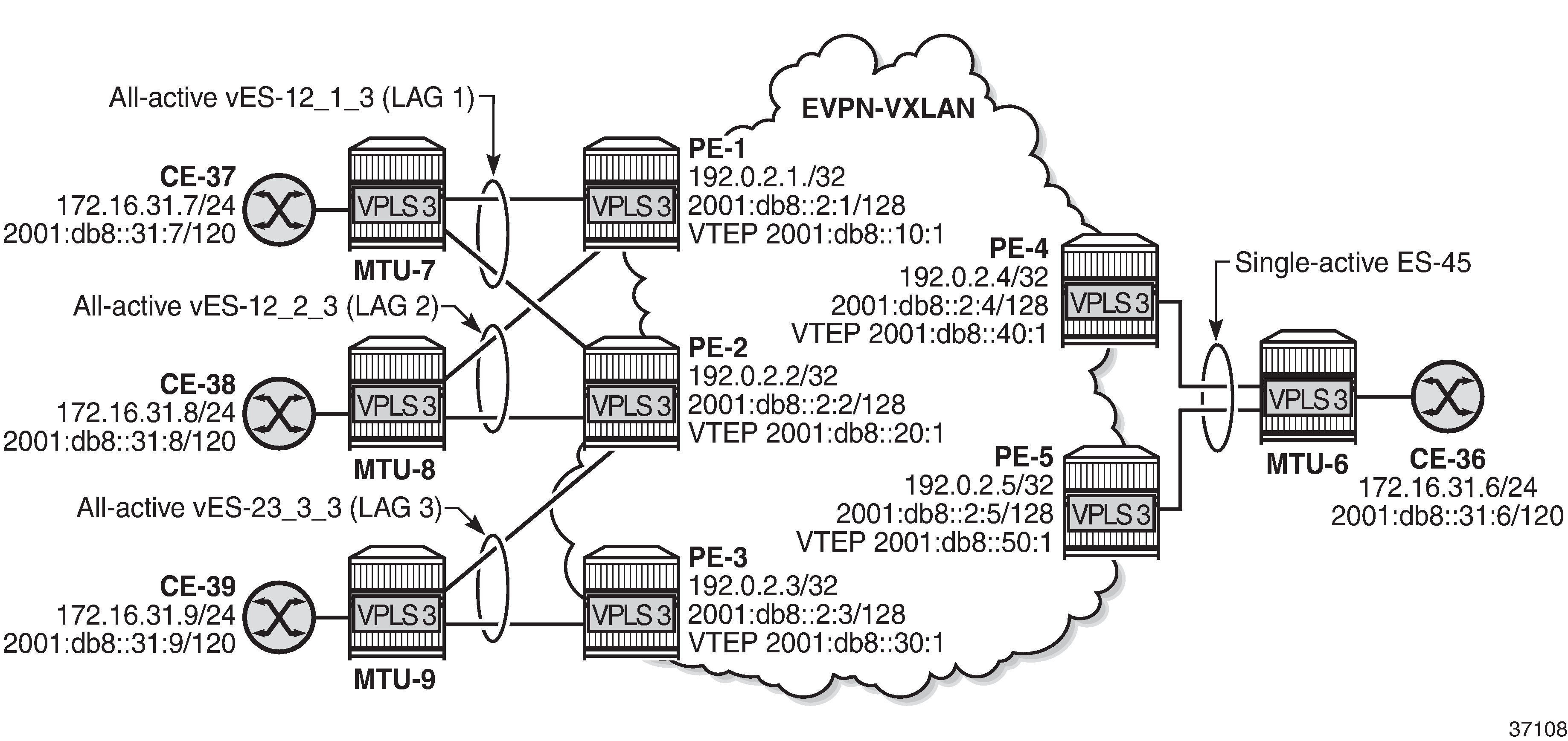
Between the PEs, the router interfaces have IPv6 addresses as well as IPv4 addresses, and ipv6-routing native is configured in IS-IS on the PEs. FPE is configured with VXLAN termination 2001:db8::x0:1 on PE-x.
The following all-active multi-homing ESs with non-system IPv6 addresses are configured on PE-2:
# on PE-2:
configure
    service
        system
            bgp-evpn
                ethernet-segment "vES-12_1_3" virtual create        # same ES on PE-1
                    esi 00:12:12:12:12:12:12:00:01:03
                    es-orig-ip 2001:db8::20:1
                    route-next-hop 2001:db8::20:1
                    service-carving
                        mode auto
                    exit
                    multi-homing all-active
                    lag 1
                    dot1q
                        q-tag-range 3
                    exit
                    no shutdown
                exit
                ethernet-segment "vES-12_2_3" virtual create        # same ES on PE-1
                    esi 00:12:12:12:12:12:12:00:02:03
                    es-orig-ip 2001:db8::20:1
                    route-next-hop 2001:db8::20:1
                    service-carving
                        mode auto
                    exit
                    multi-homing all-active
                    lag 2
                    dot1q
                        q-tag-range 3
                    exit
                    no shutdown
                exit
                ethernet-segment "vES-23_3_3" virtual create        # same ES on PE-3
                    esi 00:23:23:23:23:23:23:00:03:03
                    es-orig-ip 2001:db8::20:1
                    route-next-hop 2001:db8::20:1
                    service-carving
                        mode auto
                    exit
                    multi-homing all-active
                    lag 3
                    dot1q
                        q-tag-range 3
                    exit
                    no shutdown
                exit
            exit
        exit
"VPLS 3" is configured with non-system source VTEP 2001:db8::x0:1, as follows:
# on PE-2:
configure
    service
        vpls 3 name "VPLS 3" customer 1 create
            vxlan-src-vtep 2001:db8::20:1
            vxlan instance 1 vni 3 create
            exit
            bgp
                route-distinguisher auto-rd
                route-target export target:64500:3 import target:64500:3
            exit
            bgp-evpn
                evi 3
                vxlan bgp 1 vxlan-instance 1
                    ecmp 2
                    auto-disc-route-advertisement
                    mh-mode network
                    no shutdown
                exit
            exit
            stp
                shutdown
            exit
            sap lag-1:3 create                      # lag-1 shared with PE-1
                no shutdown
            exit
            sap lag-2:3 create                      # lag-2 shared with PE-1
                no shutdown
            exit
            sap lag-3:3 create                      # lag-3 shared with PE-3
                no shutdown
            exit
            no shutdown
        exit
Verification
The following command on PE-1 shows that the source VTEP is 2001:db8::10:1 for VPLS 3:
*A:PE-1# show service id 3 vxlan
===============================================================================
VPLS VXLAN
===============================================================================
Vxlan Src Vtep IP: 2001:db8::10:1

===============================================================================
Vxlan Instance
===============================================================================
VXLAN Instance                VNI         AR          Oper-flags   VTEP
                                                                   security
-------------------------------------------------------------------------------
1                             3           none        none         disabled
-------------------------------------------------------------------------------
Number of Entries : 1
-------------------------------------------------------------------------------
===============================================================================
The following command on PE-1 shows the non-system IPv6 destination VTEPs for VPLS 3:
*A:PE-1# show service id 3 vxlan destinations

===============================================================================
Egress VTEP, VNI
===============================================================================
Instance    VTEP Address                            Egress VNI  EvpnStatic Num
 Mcast       Oper State                              L2 PBR     SupBcasDom MACs
-------------------------------------------------------------------------------
1           2001:db8::20:1                          3           evpn       0
 BUM         Up                                      No          No
1           2001:db8::30:1                          3           evpn       0
 BUM         Up                                      No          No
1           2001:db8::40:1                          3           evpn       0
 BUM         Up                                      No          No
1           2001:db8::50:1                          3           evpn       0
 BUM         Up                                      No          No
-------------------------------------------------------------------------------
Number of Egress VTEP, VNI : 4
-------------------------------------------------------------------------------
===============================================================================

===============================================================================
BGP EVPN-VXLAN Ethernet Segment Dest
===============================================================================
Instance  Eth SegId                       Num. Macs     Last Change
-------------------------------------------------------------------------------
1         00:23:23:23:23:23:23:00:03:03   1             08/26/2021 07:41:20
1         00:45:45:45:45:45:45:00:00:03   1             08/26/2021 07:41:30
-------------------------------------------------------------------------------
Number of entries: 2
-------------------------------------------------------------------------------
===============================================================================
The following command on PE-3 shows that VTEPs 2001:db8::10:1 and 2001:db8::20:1 are destinations in the all-active ES with ESI 00:12:12:12:12:12:12:00:01:03:
*A:PE-3# show service id 3 vxlan esi 00:12:12:12:12:12:12:00:01:03

===============================================================================
BGP EVPN-VXLAN Ethernet Segment Dest
===============================================================================
Instance  Eth SegId                       Num. Macs     Last Change
-------------------------------------------------------------------------------
1         00:12:12:12:12:12:12:00:01:03   1             08/26/2021 07:41:04
-------------------------------------------------------------------------------
Number of entries: 1
-------------------------------------------------------------------------------
===============================================================================

===============================================================================
BGP EVPN-VXLAN Dest TEP Info
===============================================================================
Instance  TEP Address                   Egr VNI             Last Change
-------------------------------------------------------------------------------
1         2001:db8::10:1                3                   08/26/2021 07:41:04
1         2001:db8::20:1                3                   08/26/2021 07:41:04
-------------------------------------------------------------------------------
Number of entries : 2
-------------------------------------------------------------------------------
===============================================================================
Debug
With debugging enabled for BGP updates, the following debug message on PE-3 shows that the NextHop value is changed in the EVPN-AD routes:
17 2021/08/26 07:40:54.081 UTC MINOR: DEBUG #2001 Base Peer 1: 192.0.2.1
"Peer 1: 192.0.2.1: UPDATE
Peer 1: 192.0.2.1 - Send BGP UPDATE:
    Withdrawn Length = 0
    Total Path Attr Length = 85
    Flag: 0x90 Type: 14 Len: 48 Multiprotocol Reachable NLRI:
        Address Family EVPN
        NextHop len 16 Global NextHop 2001:db8::30:1
        Type: EVPN-AD Len: 25 RD: 192.0.2.3:3 ESI: 00:23:23:23:23:23:23:00:03:03,
                      tag: MAX-ET Label: 0 (Raw Label: 0x0) PathId:
    Flag: 0x40 Type: 1 Len: 1 Origin: 0
    Flag: 0x40 Type: 2 Len: 0 AS Path:
    Flag: 0x40 Type: 5 Len: 4 Local Preference: 100
    Flag: 0xc0 Type: 16 Len: 16 Extended Community:
        target:64500:3
        esi-label:524285/All-Active
"
The following EVPN-ETH-SEG message on PE-3 shows that the NextHop value and Orig-IP-Addr is modified to the value 2001:db8::30:1.
20 2021/08/26 07:40:54.081 UTC MINOR: DEBUG #2001 Base Peer 1: 192.0.2.1
"Peer 1: 192.0.2.1: UPDATE
Peer 1: 192.0.2.1 - Send BGP UPDATE:
    Withdrawn Length = 0
    Total Path Attr Length = 95
    Flag: 0x90 Type: 14 Len: 58 Multiprotocol Reachable NLRI:
        Address Family EVPN
        NextHop len 16 Global NextHop 2001:db8::30:1
        Type: EVPN-ETH-SEG Len: 35 RD: 192.0.2.3:0
         ESI: 00:23:23:23:23:23:23:00:03:03, IP-Len: 16 Orig-IP-Addr: 2001:db8::30:1
    Flag: 0x40 Type: 1 Len: 1 Origin: 0
    Flag: 0x40 Type: 2 Len: 0 AS Path:
    Flag: 0x40 Type: 5 Len: 4 Local Preference: 100
    Flag: 0xc0 Type: 16 Len: 16 Extended Community:
        df-election::DF-Type:Auto/DP:0/DF-Preference:0/AC:1
        target:23:23:23:23:23:23
"
Conclusion
All-active and single-active multi-homing can be configured for EVPN-VXLAN VPLSs. On all-active ESs, split-horizon for BUM traffic is based on local-bias, as described in RFC 8365.