Segment Routing with IS-IS Control Plane
This chapter provides information about Segment Routing (SR) with Intermediate System to Intermediate System (IS-IS) control plane.
Topics in this chapter include:
Applicability
Segment routing is supported in SR OS Release 13.0, and later. This chapter was initially written for SR OS Release 13.0.R3, but the MD-CLI in the current edition corresponds to SR OS Release 21.2.R1.
Overview
Segment Routing (SR) is a technology for IP/Multi-Protocol Label Switching (MPLS) networks that enables source routing. With source routing, operators can specify a forwarding path, from ingress to egress, that is independent of the shortest path determined by the Interior Gateway Protocol (IGP).
The main benefit of segment routing compared to other source routing protocols (such as ReSource reserVation Protocol with Traffic Engineering (RSVP-TE)) is that, from a control plane perspective, no signaling protocol is required. Segment routing provides a path or tunnel, encoded as a sequential list of sub-paths or segments that are advertised within the segment routing domain, using extensions to well-known link state routing protocols, such as IS-IS or Open Shortest Path First (OSPF).
Implementation
A segment routing tunnel can contain a single segment that represents the destination node, or it can contain a list of segments that the tunnel must traverse. The tunnel can be established over an IPv4/IPv6 MPLS or IPv6 data plane, encoded as a stack of MPLS labels or as a number of IPv6 addresses contained in an IPv6 extension header.
Network elements are modeled as segments. For each segment, IGP advertises an identifier referred to as a segment ID (SID).
The two segment types are:
-
Prefix segment — Globally unique and allocated from a Segment Routing Global Block (SRGB), typically multi-hop and signaled by the IGP. It is the Equal Cost Multi-Path ECMP-aware shortest path IGP route to a related prefix. A typical example of a prefix segment is a node SID. Within the SR OS implementation, the node SID is either the system address or another interface address in the Global Routing Table (GRT) of type loopback. Node SIDs are advertised in IS-IS using a prefix SID sub-TLV (Type Length Value).
-
Adjacency segment — Locally unique and allocated from the (local) dynamic label space, so that other routers in the SR domain can use the same label space. Adjacency segments are signaled by the IGP. Within the SR OS implementation, adjacency SIDs are automatically assigned and advertised when the SR context within the IGP instance is enabled. Adjacency SIDs are advertised in IS-IS using an adjacency SID sub-TLV.
To make prefix segments globally unique within the segment routing domain, an indexing mechanism is required, because production networks consist of multiple vendors and multiple products. As a result, it is often difficult to agree on a common SRGB for the prefix SIDs.
All routers within the SR domain are expected to configure and advertise the same Prefix SID index range for an IGP instance. The label value used by each router to represent a prefix can be local to that router by the use of an offset label, referred to as a start label:
Within the SR OS implementation, prefix Loop-Free Alternate (LFA) is supported for segment routing to improve the Fast ReRoute (FRR) coverage. Remote LFA (RLFA) is also supported. With RLFA, segment routing shortest path tunnels are used as a virtual LFA or repair tunnel toward the PQ node.
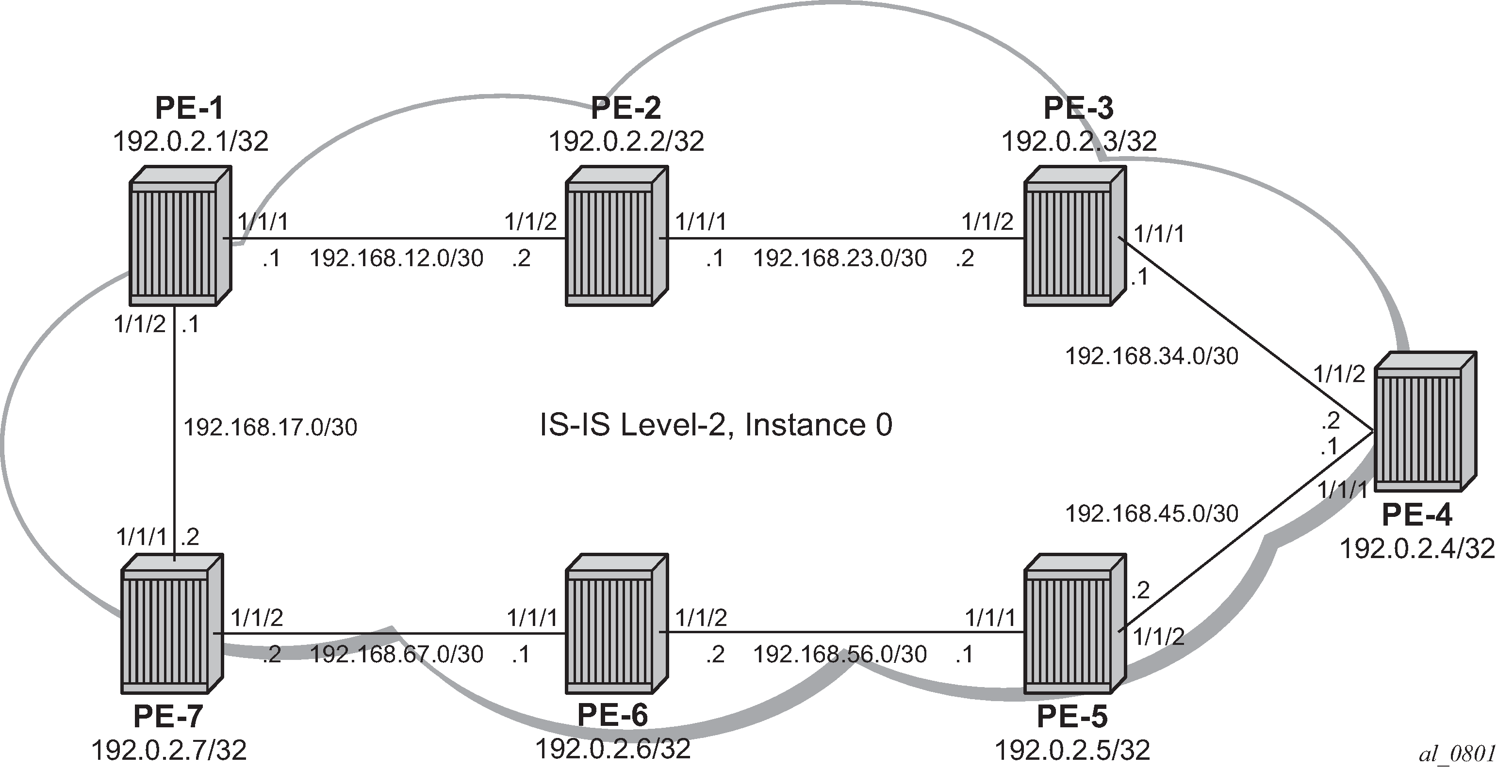
The following example uses IS-IS as an IGP protocol, with an MPLS data plane and services enabled using LFA and RLFA. Example topology shows the example topology with seven PEs.
Configuration
-
Configure router interfaces and IS-IS according to Example topology.
-
The system and IP interface addresses are configured according to Example topology.
-
IS-IS level 2 is selected as the IGP to distribute routing information between all PEs. All IS-IS interfaces are of type point-to-point to avoid running the Designated Router/Backup Designated Router (DR/BDR) election process.
-
-
Configure segment routing.
Before enabling segment routing on a router, define a dedicated SRGB. This SRGB is required on each individual router part of the SR domain and is used to allocate the Prefix SIDs.
By default, an SRGB is not instantiated and, when configured by the operator, it is taken from the system dynamic label range. By default, the following label ranges are available:
[/]
A:admin@PE-1# show router mpls-labels label-range

===============================================================================
Label Ranges
===============================================================================
Label Type      Start Label End Label   Aging       Available   Total
-------------------------------------------------------------------------------
Static          32          18431       -           18400       18400
Dynamic         18432       524287      0           505856      505856
    Seg-Route   0           0           -           0           0
===============================================================================
For simplicity, the same SRGB is used in this example for all SR domain routers. Within the command, a start value and end value define the size of the SRGB. The following command configures an SRGB of 100 MPLS labels, from label 20000 to label 20099:
# on PE-1, PE-2, PE-3, PE-4, PE-5, PE-6, PE-7:
configure {
    router "Base" {
        mpls-labels {
            sr-labels {
                start 20000
                end 20099
            }
        }
[/] A:admin@PE-1# show router mpls-labels label-range =============================================================================== Label Ranges =============================================================================== Label Type Start Label End Label Aging Available Total ------------------------------------------------------------------------------- Static 32 18431 - 18400 18400 Dynamic 18432 524287 0 505756 505856 Seg-Route 20000 20099 - 0 100 ===============================================================================This command is repeated for all other nodes. The allocated MPLS labels are only for the prefix SIDs. The adjacency SIDs, which are only locally unique, are taken from the dynamic range; in this example, between 18432 and 524287.
-
Enable router capability in the IGP instance.
It is mandatory to enable the router-capability parameter inside the IS-IS instance, to advertise SR support among the IS-IS adjacencies. By configuring this command within the IGP instance, the SR capability sub-TLV is propagated and is used to indicate the index range and the start label. The SR algorithm sub-TLV is also used to advertise the algorithm used for path calculations. Only Shortest Path First (SPF) (value 0) is defined. This is configured as follows:
# on PE-1, PE-2, PE-3, PE-4, PE-5, PE-6, PE-7:
configure {
    router "Base" {
        isis 0 {
            advertise-router-capability area
        }
The flooding parameter is a mandatory parameter in this command. The keyword area or as indicates that the router capabilities label switched path (LSP) should be advertised throughout the same level or throughout the whole Autonomous System (AS). In the preceding example, all routers belong to the same level, so the area argument is sufficient. When the SR context within the IGP instance is enabled, both IS-IS sub-TLVs are flooded.
-
Define the Prefix SID index range.
The SR OS implementation for SR provides two mutually exclusive modes of operation to define the prefix SID index range: global mode and per-instance mode. Per-instance mode is useful in a seamless MPLS environment when multiple IGP instances are used. The main difference between the modes is the way that the start label and index range are calculated.
A comparison of the modes is shown in following table:
Table 1. Mode comparison Global
Per instance
Applicable for all IGP instances on that node
Applicable for one dedicated IGP instance
Start label is first label of SRGB
Start label is configurable (but part of SRGB range); use of non-overlapping sub-ranges of SRGB
Prefix SID index range is ‟size” of SRGB
Prefix SID index-range is configurable
If SRGB needs to change, disable SR and delete prefix-SID-ranges in all IGP instances
If prefix SID index and/or label range needs to change, disable SR in that specific IGP instance
SW checks whether any allocated SID index/label goes out of range.
SW checks also for overlaps of the resulting net label value range across IGP instances.
For simplicity, global mode is used for this example, as follows:
# on PE-1, PE-2, PE-3, PE-4, PE-5, PE-6, PE-7: configure { router "Base" { isis 0 { segment-routing { prefix-sid-range { global } } -
Assign a prefix SID index or label to the prefix representing a node.
To be able to set up SR shortest path tunnels to all routers of the SR domain, each router needs to be uniquely defined within the SR domain. Therefore, the system address or other loopback interface in the GRT will be assigned an ipv4-node-sid index or label value that is unique within the SR domain. The prefix SID index is assigned as follows:
# on PE-1:
configure {
    router "Base" {
        isis 0 {
            interface "system" {
                ipv4-node-sid {
                    index 1
                }
            }
# on PE-2: configure { router "Base" { isis 0 { interface "system" { ipv4-node-sid { index 2 } }# on PE-3: configure { router "Base" { isis 0 { interface "system" { ipv4-node-sid { index 3 } }# on PE-4: configure { router "Base" { isis 0 { interface "system" { ipv4-node-sid { index 4 } }# on PE-5: configure { router "Base" { isis 0 { interface "system" { ipv4-node-sid { index 5 } }# on PE-6: configure { router "Base" { isis 0 { interface "system" { ipv4-node-sid { index 6 } }# on PE-7: configure { router "Base" { isis 0 { interface "system" { ipv4-node-sid { index 7 } }Because the SRGB is the same on all nodes, each node in the network can be reached using the same MPLS label. For example, the node SID for PE-5 on all nodes has a start label (first label of the SRGB (= 20000) + ipv4-node-sid index on node PE-5 (= 5)) of 20005.
When there is one consistent SRGB for the SR domain, the SR OS allows the use of absolute MPLS label values instead of index values. For example, on PE-1, an operator can use an explicit MPLS label value, as follows:
# on PE-1:
configure {
    router "Base" {
        isis 0 {
            interface "system" {
                ipv4-node-sid {
                    label 20001
                }
            }
        }
Internally, this explicit value is translated into an index value (index-value 1) before advertising it toward its neighbors, taking into account the prefix SID index-range mode (global or per-instance) and the SRGB.
-
Enable SR context within the IGP instance, as follows:
# on PE-1, PE-2, PE-3, PE-4, PE-5, PE-6, PE-7:
configure {
    router "Base" {
        isis 0 {
            segment-routing {
                admin-state enable
            }
        }
After enabling the SR context within an IGP instance, the SR capability sub-TLV, and the SR algorithm sub-TLV between all routers within the SR domain, are flooded. The following show command displays the SR related router capability information on PE-1:
[/]
A:admin@PE-1# show router isis capabilities level 2

===============================================================================
Rtr Base ISIS Instance 0 Capabilities
===============================================================================
Displaying Level 2 capabilities
-------------------------------------------------------------------------------
LSP ID    : PE-1.00-00
  Router Cap : 192.0.2.1, D:0, S:0
    TE Node Cap : B E M  P
    SR Cap: IPv4 MPLS-IPv6
       SRGB Base:20000, Range:100
    SR Alg: metric based SPF
    Node MSD Cap: BMI : 12 ERLD : 15
LSP ID    : PE-2.00-00
  Router Cap : 192.0.2.2, D:0, S:0
    TE Node Cap : B E M  P
    SR Cap: IPv4 MPLS-IPv6
       SRGB Base:20000, Range:100
    SR Alg: metric based SPF
    Node MSD Cap: BMI : 12 ERLD : 15
LSP ID    : PE-3.00-00
  Router Cap : 192.0.2.3, D:0, S:0
    TE Node Cap : B E M  P
    SR Cap: IPv4 MPLS-IPv6
       SRGB Base:20000, Range:100
    SR Alg: metric based SPF
    Node MSD Cap: BMI : 12 ERLD : 15
LSP ID    : PE-4.00-00
  Router Cap : 192.0.2.4, D:0, S:0
    TE Node Cap : B E M  P
    SR Cap: IPv4 MPLS-IPv6
       SRGB Base:20000, Range:100
    SR Alg: metric based SPF
    Node MSD Cap: BMI : 12 ERLD : 15
LSP ID    : PE-5.00-00
  Router Cap : 192.0.2.5, D:0, S:0
    TE Node Cap : B E M  P
    SR Cap: IPv4 MPLS-IPv6
       SRGB Base:20000, Range:100
    SR Alg: metric based SPF
    Node MSD Cap: BMI : 12 ERLD : 15
LSP ID    : PE-6.00-00
  Router Cap : 192.0.2.6, D:0, S:0
    TE Node Cap : B E M  P
    SR Cap: IPv4 MPLS-IPv6
       SRGB Base:20000, Range:100
    SR Alg: metric based SPF
    Node MSD Cap: BMI : 12 ERLD : 15
LSP ID    : PE-7.00-00
  Router Cap : 192.0.2.7, D:0, S:0
    TE Node Cap : B E M  P
    SR Cap: IPv4 MPLS-IPv6
       SRGB Base:20000, Range:100
    SR Alg: metric based SPF
    Node MSD Cap: BMI : 12 ERLD : 15
Level (2) Capability Count : 7
===============================================================================
A similar output occurs for each router in the SR domain.
After enabling the SR context within the IGP instance, the assigned index for each locally configured prefix SID is advertised. After the advertisement of prefix SIDs, MPLS data plane Ingress Label Mapping (ILM) is programmed with a pop operation. In this context, a show command can be used to display the prefix SIDs, in order, within the SR domain. As an example, on PE-1, this becomes:
[/]
A:admin@PE-1# show router isis prefix-sids

===============================================================================
Rtr Base ISIS Instance 0 Prefix/SID Table
===============================================================================
Prefix                            SID        Lvl/Typ    SRMS   AdvRtr
                                                         MT     Flags-------------------------------------------------------------------------------
192.0.2.1/32                      1          2/Int.      N     PE-1
                                                            0      NnP
192.0.2.2/32                      2          2/Int.      N     PE-2
                                                            0      NnP
192.0.2.3/32                      3          2/Int.      N     PE-3
                                                            0      NnP
192.0.2.4/32                      4          2/Int.      N     PE-4
                                                            0      NnP
192.0.2.5/32                      5          2/Int.      N     PE-5
                                                            0      NnP
192.0.2.6/32                      6          2/Int.      N     PE-6
                                                            0      NnP
192.0.2.7/32                      7          2/Int.      N     PE-7
                                                            0      NnP-------------------------------------------------------------------------------
No. of Prefix/SIDs: 7 (7 unique)
-------------------------------------------------------------------------------
SRMS : Y/N  = prefix SID advertised by SR Mapping Server (Y) or not (N)
       S    = SRMS prefix SID is selected to be programmed
Flags: R    = Re-advertisement
       N    = Node-SID       nP   = no penultimate hop POP
       E    = Explicit-Null
       V    = Prefix-SID carries a value
       L    = value/index has local significance
===============================================================================
By default, the SR OS implementation sets the node SID (or N–flag) and no Penultimate hop PoP (or nP–flag) inside the prefix SID TLV. Another useful flag that can be set is the re-advertisement (or R-flag). The R-flag is set when a prefix SID is propagated between levels or areas, or redistribution is in place (from another protocol).
Prefix SID information can also be viewed within the IGP database attached to (extended) IP prefix reachability TLVs. For example, on PE-1, as follows:
[/]
A:admin@PE-1# show router isis database PE-1.00-00 detail level 2

===============================================================================
Rtr Base ISIS Instance 0 Database (detail)
===============================================================================

Displaying Level 2 database
-------------------------------------------------------------------------------
LSP ID    : PE-1.00-00                                  Level     : L2
Sequence  : 0x6                    Checksum  : 0xc640   Lifetime  : 971
Version   : 1                      Pkt Type  : 20       Pkt Ver   : 1
Attributes: L1L2                   Max Area  : 3        Alloc Len : 1492
SYS ID    : 1920.0000.2001         SysID Len : 6        Used Len  : 254

TLVs :
  Supp Protocols:
    Protocols     : IPv4
  IS-Hostname   : PE-1
  Router ID   :
    Router ID   : 192.0.2.1
  Router Cap : 192.0.2.1, D:0, S:0
    TE Node Cap : B E M  P
    SR Cap: IPv4 MPLS-IPv6
       SRGB Base:20000, Range:100
    SR Alg: metric based SPF
    Node MSD Cap: BMI : 12 ERLD : 15
---snip---
  Internal Reach:
---snip---
    Default Metric: (I) 0
    Delay Metric  : (I) 0
    Expense Metric: (I) 0
    Error Metric  : (I) 0
    IP Address    : 192.0.2.1
    IP Mask       : 255.255.255.255
  I/F Addresses :
    I/F Address   : 192.0.2.1
---snip---
  TE IP Reach   :
---snip---
    Default Metric  : 0
    Control Info:   S, prefLen 32
    Prefix   : 192.0.2.1
    Sub TLV   :
      Prefix-SID Index:1, Algo:0, Flags:NnP

Level (2) LSP Count : 1
-------------------------------------------------------------------------------
---snip---
Prefix-SID Flags : R = Re-advertisement Flag
                   N = Node-SID Flag
                   nP = no penultimate hop POP
                   E = Explicit-Null Flag
                   V = Prefix-SID carries a value
                   L = value/index has local significance
---snip---
===============================================================================
After enabling the SR context within the IGP instance, adjacency SIDs are also automatically assigned and advertised for each formed adjacency over an IP interface. From a data plane perspective, one local adjacency SID consumes one ILM entry, programming a pop operation.
Similar to prefix SIDs, adjacency SID information can be viewed within the IGP database attached to IS neighbor TLVs, as follows:
[/]A:admin@PE-1# show router isis database PE-1.00-00 detail level 2

===============================================================================
Rtr Base ISIS Instance 0 Database (detail)
===============================================================================

Displaying Level 2 database
-------------------------------------------------------------------------------
LSP ID    : PE-1.00-00                                  Level     : L2
Sequence  : 0x6                    Checksum  : 0xc640   Lifetime  : 971
Version   : 1                      Pkt Type  : 20       Pkt Ver   : 1
Attributes: L1L2                   Max Area  : 3        Alloc Len : 1492
SYS ID    : 1920.0000.2001         SysID Len : 6        Used Len  : 254

TLVs :
  Supp Protocols:
    Protocols     : IPv4
  IS-Hostname   : PE-1
  Router ID   :
    Router ID   : 192.0.2.1
---snip---
  IS Neighbors  :
    Virtual Flag  : 0
    Default Metric: (I) 10
    Delay Metric  : (I) 0
    Expense Metric: (I) 0
    Error Metric  : (I) 0
    Neighbor      : PE-2.00
  IS Neighbors  :
    Virtual Flag  : 0
    Default Metric: (I) 10
    Delay Metric  : (I) 0
    Expense Metric: (I) 0
    Error Metric  : (I) 0
    Neighbor      : PE-7.00
  Internal Reach:
    Default Metric: (I) 10
    Delay Metric  : (I) 0
    Expense Metric: (I) 0
    Error Metric  : (I) 0
    IP Address    : 192.168.12.0
    IP Mask       : 255.255.255.252
    Default Metric: (I) 10
    Delay Metric  : (I) 0
    Expense Metric: (I) 0
    Error Metric  : (I) 0
    IP Address    : 192.168.17.0
    IP Mask       : 255.255.255.252
---snip---
  I/F Addresses :
---snip---
    I/F Address   : 192.168.12.1
    I/F Address   : 192.168.17.1
  TE IS Nbrs   :
    Nbr   : PE-2.00
    Default Metric  : 10
    Sub TLV Len     : 19
    IF Addr   : 192.168.12.1
    Nbr IP    : 192.168.12.2
    Adj-SID: Flags:v4VL Weight:0 Label:524287
  TE IS Nbrs   :    Nbr   : PE-7.00
    Default Metric  : 10
    Sub TLV Len     : 19
    IF Addr   : 192.168.17.1
    Nbr IP    : 192.168.17.2
    Adj-SID: Flags:v4VL Weight:0 Label:524286
  TE IP Reach   :
    Default Metric  : 10
    Control Info:    , prefLen 30
    Prefix   : 192.168.12.0
    Default Metric  : 10
    Control Info:    , prefLen 30
    Prefix   : 192.168.17.0
---snip---

Level (2) LSP Count : 1
--------------------------------------------------------------------------------
--snip---
Adj-SID Flags    : v4/v6 = IPv4 or IPv6 Address-Family
                   B = Backup Flag
                   V = Adj-SID carries a value
                   L = value/index has local significance
                   S = Set of Adjacencies
                   P = Persistently allocated
---snip---
===============================================================================
By default, the SR OS implementation sets the value (V–flag), meaning that the adjacency SID carries a value (as opposed to an index). Also, the local L-flag is set by default, meaning that the adjacency SID has only local significance. The v4-flag set to 0 means that the adjacency SID references to an adjacency with outgoing IPv4 encapsulation.
Another way to display adjacency SID information is using the show router isis adjacency detail command.
[/]
A:admin@PE-1# show router isis adjacency "int-PE-1-PE-2" detail

===============================================================================
Rtr Base ISIS Instance 0 Adjacency (detail)
===============================================================================
Hostname   : PE-2
SystemID    : 1920.0000.2002                   SNPA        : 04:14:01:01:00:02
Interface   : int-PE-1-PE-2                    Up Time     : 0d 00:12:53
State       : Up                               Priority    : 0
Nbr Sys Typ : L2                               L. Circ Typ : L2
Hold Time   : 19                               Max Hold    : 27
Adj Level   : L2                               MT Enabled  : No
Topology    : Unicast

IPv6 Neighbor     : ::
IPv4 Neighbor     : 192.168.12.2
IPv4 Adj SID      : Label 524287
Restart Support   : Disabled
Restart Status    : Not currently being helped
Restart Supressed : Disabled
Number of Restarts: 0
Last Restart at   : Never

===============================================================================
[/] A:admin@PE-1# show router isis adjacency "int-PE-1-PE-7" detail =============================================================================== Rtr Base ISIS Instance 0 Adjacency (detail) =============================================================================== Hostname : PE-7 SystemID : 1920.0000.2007 SNPA : 04:27:01:01:00:01 Interface : int-PE-1-PE-7 Up Time : 0d 00:10:41 State : Up Priority : 0 Nbr Sys Typ : L2 L. Circ Typ : L2 Hold Time : 25 Max Hold : 27 Adj Level : L2 MT Enabled : No Topology : Unicast IPv6 Neighbor : :: IPv4 Neighbor : 192.168.17.2 IPv4 Adj SID : Label 524286 Restart Support : Disabled Restart Status : Not currently being helped Restart Supressed : Disabled Number of Restarts: 0 Last Restart at : Never ===============================================================================
Finally, when enabling the SR context within the IGP instance, the SR module resolves received prefixes with prefix SID sub-TLVs present. As a result, MPLS data plane resources are consumed. The ILM is programmed with a swap operation and the label-to-next-hop-label-forwarding-entry (LTN) with a push operation, both pointing to the primary and/or LFA next-hop label forwarding entry (NHLFE). Also, an SR tunnel is added in the Tunnel Table Manager (TTM). As a result, an SR shortest path tunnel is set up to each other router that is part of the SR domain. Now, SR shortest path tunnels can be used for all users of TTM.
Example 1: VPRN service with LFA and RLFA enabled
In the network topology of Example topology, no LDP and RSVP-TE signaling protocols are enabled. Each router of the SR domain has a full mesh of SR shortest path tunnels to the other routers, and no LDP and RSVP-TE LSPs are present. For example, on PE-1, the TTM looks as follows:
[/]
A:admin@PE-1# show router tunnel-table

===============================================================================
IPv4 Tunnel Table (Router: Base)
===============================================================================
Destination           Owner     Encap TunnelId  Pref   Nexthop        Metric
   Color
-------------------------------------------------------------------------------
192.0.2.2/32          isis (0)  MPLS  524291    11     192.168.12.2   10
192.0.2.3/32          isis (0)  MPLS  524292    11     192.168.12.2   20
192.0.2.4/32          isis (0)  MPLS  524293    11     192.168.12.2   30
192.0.2.5/32          isis (0)  MPLS  524296    11     192.168.17.2   30
192.0.2.6/32          isis (0)  MPLS  524294    11     192.168.17.2   20
192.0.2.7/32          isis (0)  MPLS  524295    11     192.168.17.2   10
192.168.12.2/32       isis (0)  MPLS  524289    11     192.168.12.2   0
192.168.17.2/32       isis (0)  MPLS  524290    11     192.168.17.2   0
-------------------------------------------------------------------------------
Flags: B = BGP or MPLS backup hop available
       L = Loop-Free Alternate (LFA) hop available
       E = Inactive best-external BGP route
       k = RIB-API or Forwarding Policy backup hop
===============================================================================
The objective is to configure a VPRN between PE-1 and PE-7, using SR shortest path tunnels as transport tunnel. The configuration is as follows:
# on PE-1:
configure {
    service {
        vprn "VPRN100" {
            admin-state enable
            service-id 100
            customer "1"
            autonomous-system 64496
            bgp-ipvpn {
                mpls {
                    admin-state enable
                    route-distinguisher "64496:10001"
                    vrf-target {
                        community "target:64496:100"
                    }
                    auto-bind-tunnel {
                        resolution any
                    }
                }
            }
            interface "loopback" {
                loopback true
                ipv4 {
                    primary {
                        address 192.0.1.1
                        prefix-length 32
                    }
                }
            }
# on PE-7: configure { service { vprn "VPRN100" { admin-state enable service-id 100 customer "1" autonomous-system 64496 bgp-ipvpn { mpls { admin-state enable route-distinguisher "64496:10007" vrf-target { community "target:64496:100" } auto-bind-tunnel { resolution any } } } interface "loopback" { loopback true ipv4 { primary { address 192.0.1.7 prefix-length 32 } } }Within the VPRN service configuration, a loopback interface is created on both PEs to verify the transport mechanism. Tunnel information displaying the MPLS label value is retrieved using the show router fp-tunnel-table <slot number> command, as follows:
[/]A:admin@PE-1# show router fp-tunnel-table 1
    ===============================================================================
    IPv4 Tunnel Table Display

    Legend:
    label stack is ordered from bottom-most to top-most
    B - FRR Backup
    ===============================================================================
    Destination                                  Protocol            Tunnel-ID
        Lbl
            NextHop                                                   Intf/Tunnel
        Lbl     (backup)
            NextHop   (backup)
    -------------------------------------------------------------------------------
    192.0.2.2/32                                 SR-ISIS-0            524291
        20002
            192.168.12.2                                                  1/1/1
    192.0.2.3/32                                 SR-ISIS-0            524292
        20003
            192.168.12.2                                                  1/1/1
    192.0.2.4/32                                 SR-ISIS-0            524293
        20004
            192.168.12.2                                                  1/1/1
    192.0.2.5/32                                 SR-ISIS-0            524296
        20005
            192.168.17.2                                                  1/1/2
    192.0.2.6/32                                 SR-ISIS-0            524294
        20006
            192.168.17.2                                                  1/1/2
    192.0.2.7/32                                 SR-ISIS-0            524295
        20007
            192.168.17.2                                                  1/1/2
    192.168.12.2/32                              SR                   524289
        3
            192.168.12.2                                                  1/1/1
    192.168.17.2/32                              SR                   524290
        3
            192.168.17.2                                                  1/1/2
-------------------------------------------------------------------------------
Total Entries : 8
-------------------------------------------------------------------------------
===============================================================================
This means that, when traffic arrives on PE-1, the MPLS label 20007 is pushed to reach destination PE-7. Because, in this example, the prefix SID index range global mode is used, the value 20007 comes from the start label on PE-7 (first label of the SRGB, which is 20000, plus the configured index value of node SID PE-7 (7)), so 20007.
Enabling prefix LFA within the IS-IS context on PE-1 will enable LFA/FRR protection. Next-hop LFA protection is present for node PE-4, node PE-5, and the link between PE-4 and PE-5, as follows:
# on PE-1:
configure {
    router "Base" {
        isis 0 {
            loopfree-alternate {
            }
        }
[/] A:admin@PE-1# show router isis lfa-coverage =============================================================================== Rtr Base ISIS Instance 0 LFA Coverage =============================================================================== Topology Level Node IPv4 IPv6 ------------------------------------------------------------------------------- IPV4 Unicast L1 0/0(0%) 3/11(27%) 0/0(0%) IPV6 Unicast L1 0/0(0%) 0/0(0%) 0/0(0%) IPV4 Multicast L1 0/0(0%) 0/0(0%) 0/0(0%) IPV6 Multicast L1 0/0(0%) 0/0(0%) 0/0(0%) IPV4 Unicast L2 2/6(33%) 3/11(27%) 0/0(0%) IPV6 Unicast L2 0/0(0%) 0/0(0%) 0/0(0%) IPV4 Multicast L2 0/0(0%) 0/0(0%) 0/0(0%) IPV6 Multicast L2 0/0(0%) 0/0(0%) 0/0(0%) ===============================================================================[/]A:admin@PE-1# show router route-table alternative =============================================================================== Route Table (Router: Base) =============================================================================== Dest Prefix[Flags] Type Proto Age Pref Next Hop[Interface Name] Metric Alt-NextHop Alt- Metric ------------------------------------------------------------------------------- 192.0.2.1/32 Local Local 00h54m06s 0 system 0 192.0.2.2/32 Remote ISIS 00h44m31s 18 192.168.12.2 10 192.0.2.3/32 Remote ISIS 00h44m15s 18 192.168.12.2 20 192.0.2.4/32 Remote ISIS 00h44m14s 18 192.168.12.2 30 192.168.17.2 (LFA) 40 192.0.2.5/32 Remote ISIS 00h44m08s 18 192.168.17.2 30 192.168.12.2 (LFA) 40 192.0.2.6/32 Remote ISIS 00h44m08s 18 192.168.17.2 20 192.0.2.7/32 Remote ISIS 00h44m08s 18 192.168.17.2 10 192.168.12.0/30 Local Local 00h54m06s 0 int-PE-1-PE-2 0 192.168.17.0/30 Local Local 00h54m06s 0 int-PE-1-PE-7 0 192.168.23.0/30 Remote ISIS 00h53m35s 18 192.168.12.2 20 192.168.34.0/30 Remote ISIS 00h53m05s 18 192.168.12.2 30 192.168.45.0/30 Remote ISIS 00h52m35s 18 192.168.12.2 40 192.168.17.2 (LFA) 50 192.168.56.0/30 Remote ISIS 00h51m24s 18 192.168.17.2 30 192.168.67.0/30 Remote ISIS 00h51m24s 18 192.168.17.2 20 ------------------------------------------------------------------------------- No. of Routes: 14 Flags: n = Number of times nexthop is repeated Backup = BGP backup route LFA = Loop-Free Alternate nexthop S = Sticky ECMP requested ===============================================================================[/]A:admin@PE-1# show router fp-tunnel-table 1 =============================================================================== IPv4 Tunnel Table Display Legend: label stack is ordered from bottom-most to top-most B - FRR Backup =============================================================================== Destination Protocol Tunnel-ID Lbl NextHop Intf/Tunnel Lbl (backup) NextHop (backup) ------------------------------------------------------------------------------- 192.0.2.2/32 SR-ISIS-0 524291 20002 192.168.12.2 1/1/1 192.0.2.3/32 SR-ISIS-0 524292 20003 192.168.12.2 1/1/1 192.0.2.4/32 SR-ISIS-0 524293 20004 192.168.12.2 1/1/1 20004 192.168.17.2(B) 1/1/2 192.0.2.5/32 SR-ISIS-0 524296 20005 192.168.17.2 1/1/2 20005 192.168.12.2(B) 1/1/1 192.0.2.6/32 SR-ISIS-0 524294 20006 192.168.17.2 1/1/2 192.0.2.7/32 SR-ISIS-0 524295 20007 192.168.17.2 1/1/2 192.168.12.2/32 SR 524289 3 192.168.12.2 1/1/1 192.168.17.2/32 SR 524290 3 192.168.17.2 1/1/2 ------------------------------------------------------------------------------- Total Entries : 8 ------------------------------------------------------------------------------- ===============================================================================[/]A:admin@PE-1# show router tunnel-table detail =============================================================================== Tunnel Table (Router: Base) =============================================================================== Destination : 192.0.2.2/32 NextHop : 192.168.12.2 Tunnel Flags : entropy-label-capable Age : 00h01m02s CBF Classes : (Not Specified) Owner : isis (0) Encap : MPLS Tunnel ID : 524291 Preference : 11 Tunnel Label : 20002 Tunnel Metric : 10 Tunnel MTU : 1560 Max Label Stack : 1 ------------------------------------------------------------------------------- Destination : 192.0.2.3/32 NextHop : 192.168.12.2 Tunnel Flags : entropy-label-capable Age : 00h01m02s CBF Classes : (Not Specified) Owner : isis (0) Encap : MPLS Tunnel ID : 524292 Preference : 11 Tunnel Label : 20003 Tunnel Metric : 20 Tunnel MTU : 1560 Max Label Stack : 1 ------------------------------------------------------------------------------- Destination : 192.0.2.4/32 [L] NextHop : 192.168.12.2 Tunnel Flags : has-lfa entropy-label-capable Age : 00h01m01s CBF Classes : (Not Specified) Owner : isis (0) Encap : MPLS Tunnel ID : 524293 Preference : 11 Tunnel Label : 20004 Tunnel Metric : 30 Tunnel MTU : 1560 Max Label Stack : 1 ------------------------------------------------------------------------------- Destination : 192.0.2.5/32 [L] NextHop : 192.168.17.2 Tunnel Flags : has-lfa entropy-label-capable Age : 00h01m01s CBF Classes : (Not Specified) Owner : isis (0) Encap : MPLS Tunnel ID : 524296 Preference : 11 Tunnel Label : 20005 Tunnel Metric : 30 Tunnel MTU : 1560 Max Label Stack : 1 ------------------------------------------------------------------------------- Destination : 192.0.2.6/32 NextHop : 192.168.17.2 Tunnel Flags : entropy-label-capable Age : 00h01m02s CBF Classes : (Not Specified) Owner : isis (0) Encap : MPLS Tunnel ID : 524294 Preference : 11 Tunnel Label : 20006 Tunnel Metric : 20 Tunnel MTU : 1560 Max Label Stack : 1 ------------------------------------------------------------------------------- Destination : 192.0.2.7/32 NextHop : 192.168.17.2 Tunnel Flags : entropy-label-capable Age : 00h01m02s CBF Classes : (Not Specified) Owner : isis (0) Encap : MPLS Tunnel ID : 524295 Preference : 11 Tunnel Label : 20007 Tunnel Metric : 10 Tunnel MTU : 1560 Max Label Stack : 1 ------------------------------------------------------------------------------- Destination : 192.168.12.2/32 NextHop : 192.168.12.2 Tunnel Flags : is-adjacency-tunnel Age : 00h01m02s CBF Classes : (Not Specified) Owner : isis (0) Encap : MPLS Tunnel ID : 524289 Preference : 11 Tunnel Label : 3 Tunnel Metric : 0 Tunnel MTU : 1560 Max Label Stack : 1 ------------------------------------------------------------------------------- Destination : 192.168.17.2/32 NextHop : 192.168.17.2 Tunnel Flags : is-adjacency-tunnel Age : 00h01m02s CBF Classes : (Not Specified) Owner : isis (0) Encap : MPLS Tunnel ID : 524290 Preference : 11 Tunnel Label : 3 Tunnel Metric : 0 Tunnel MTU : 1560 Max Label Stack : 1 ------------------------------------------------------------------------------- Number of tunnel-table entries : 8 Number of tunnel-table entries with LFA : 2 ===============================================================================When a failure occurs on the primary SR path (only applicable for prefix PE-4/PE-5 and the link between PE-4 and PE-5), the traffic takes the LFA backup SR path to the destination using the same MPLS label value.
To extend the LFA/FRR coverage, for example, to find an LFA protection for node PE-7, which is one of the VPRN service endpoints, RLFA can be enabled. RLFA creates a virtual LFA by using a repair tunnel to carry packets to a point in the network from where they will not be looped back to the source, but forwarded (SPF-based) toward the destination prefix.
The RLFA implementation uses the PQ algorithm. The node where RLFA is configured (PE-1 in this example) computes an extended P-space and a Q-space. The intersection of both spaces is called the PQ-node. This PQ node is the destination node of the repair tunnel using an SR shortest path tunnel. To compute both spaces, SPF is used.
In this example, IS-IS is used as the IGP, using a default metric value of 10 for all links. With the assumption that the link between PE-1 and PE-7 is broken, the calculation of both the extended P-space and the Q-space at PE-1 is as follows:
-
extended P-space — An SPF computed from node PE-1 and rooted at PE-2. It is used to calculate the set of routers that are reachable without any path transiting the protected link between PE-1 and PE-7. The following nodes belong to the extended P-space: PE-2, PE-3, PE-4, and PE-5.
-
Q-space — A reverse SPF computed from PE-1 and rooted from PE-7 (acting as destination proxy). It is used to calculate the set of routers that can reach PE-7 without transiting the protected link between PE-1 and PE-7. The nodes PE-4, PE-5, and PE-6 belong to the Q-space.
Possible PQ-nodes are PE-4 or PE-5, because they are in the intersection of both spaces.
RLFA is configured as follows:
# on PE-1:
configure {
    router "Base" {
        isis 0 {
            loopfree-alternate {
                remote-lfa
            }
        }
The nodes PE-2, PE-3, PE-6, and PE-7 now have RLFA protection, whereas PE-4 and PE-5 have LFA protection.
[/]A:admin@PE-1# show router fp-tunnel-table 1

===============================================================================
IPv4 Tunnel Table Display

Legend: label stack is ordered from bottom-most to top-most
B - FRR Backup
===============================================================================
Destination                                  Protocol            Tunnel-ID
    Lbl
        NextHop                                                  Intf/Tunnel
    Lbl     (backup)
        NextHop   (backup)
-------------------------------------------------------------------------------
192.0.2.2/32                                 SR-ISIS-0            524291
  20002
    192.168.12.2                                                  1/1/1
  20002/20005
    192.168.17.2(B)                                               1/1/2
192.0.2.3/32                                 SR-ISIS-0            524292
  20003
    192.168.12.2                                                  1/1/1
  20003/20005
    192.168.17.2(B)                                               1/1/2
192.0.2.4/32                                 SR-ISIS-0            524293
  20004
    192.168.12.2                                                  1/1/1
  20004
    192.168.17.2(B)                                               1/1/2
192.0.2.5/32                                 SR-ISIS-0            524296
  20005
    192.168.17.2                                                  1/1/2
  20005
    192.168.12.2(B)                                               1/1/1
192.0.2.6/32                                 SR-ISIS-0            524294
  20006
    192.168.17.2                                                  1/1/2
  20006/20004
    192.168.12.2(B)                                               1/1/1
192.0.2.7/32                                 SR-ISIS-0            524295
  20007
    192.168.17.2                                                  1/1/2
  20007/20004
    192.168.12.2(B)                                               1/1/1
192.168.12.2/32                              SR                   524289
  3
    192.168.12.2                                                  1/1/1
  20002/20005
    192.168.17.2(B)                                               1/1/2
192.168.17.2/32                              SR                   524290
  3
    192.168.17.2                                                  1/1/2
  20007/20004
    192.168.12.2(B)                                               1/1/1
-------------------------------------------------------------------------------
Total Entries : 8
-------------------------------------------------------------------------------
===============================================================================
The main difference between normal prefix LFA and RLFA is that for RLFA a two-MPLS label stack is pushed by the head-end node (PE-1). The top label is the SR-label to reach the PQ node (for example, 20004 for PE-4) and the bottom label is the SR-label to reach the destination node (for example, 20007 for PE-7). The notation inside the show command is bottom-label/top-label.
RLFA traffic path during protection illustrates the RLFA traffic path protecting the link between PE-1 and PE-7:
Figure 2. RLFA traffic path during protection 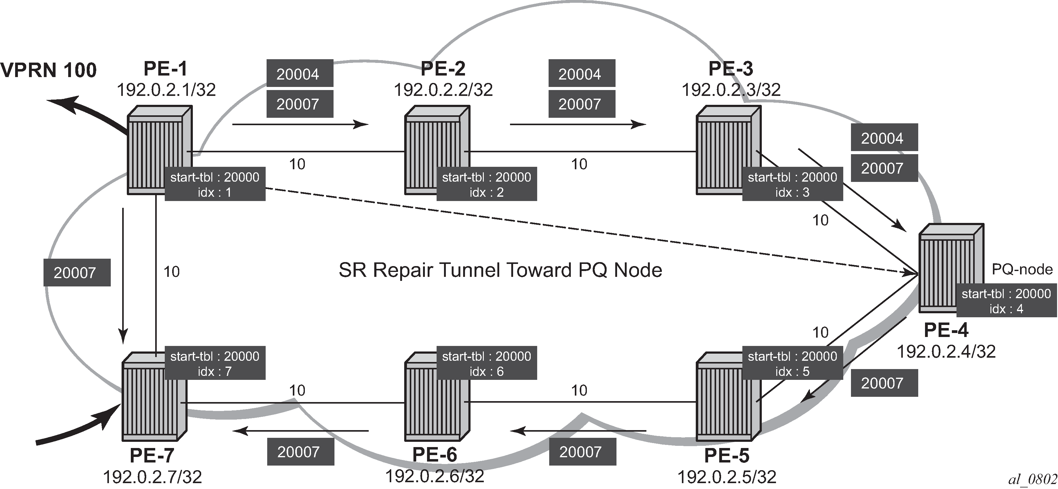
Inside the TTM, a tunnel-flag, has-lfa, is set for all destination nodes that have LFA protection available. The last two tunnels are adjacency tunnels and have in addition the flag is-adjacency-tunnel.
[/]A:admin@PE-1# show router tunnel-table detail

===============================================================================
Tunnel Table (Router: Base)
===============================================================================
Destination      : 192.0.2.2/32 [L]
NextHop          : 192.168.12.2
Tunnel Flags     : has-lfa entropy-label-capable
Age              : 00h00m41s
CBF Classes      : (Not Specified)
Owner            : isis (0)             Encap            : MPLS
Tunnel ID        : 524291               Preference       : 11
Tunnel Label     : 20002                Tunnel Metric    : 10
Tunnel MTU       : 1556                 Max Label Stack  : 2
-------------------------------------------------------------------------------
Destination      : 192.0.2.3/32 [L]
NextHop          : 192.168.12.2
Tunnel Flags     : has-lfa entropy-label-capable
Age              : 00h00m41s
CBF Classes      : (Not Specified)
Owner            : isis (0)             Encap            : MPLS
Tunnel ID        : 524292               Preference       : 11
Tunnel Label     : 20003                Tunnel Metric    : 20
Tunnel MTU       : 1556                 Max Label Stack  : 2
-------------------------------------------------------------------------------
Destination      : 192.0.2.4/32 [L]
NextHop          : 192.168.12.2
Tunnel Flags     : has-lfa entropy-label-capable
Age              : 00h00m42s
CBF Classes      : (Not Specified)
Owner            : isis (0)             Encap            : MPLS
Tunnel ID        : 524293               Preference       : 11
Tunnel Label     : 20004                Tunnel Metric    : 30
Tunnel MTU       : 1556                 Max Label Stack  : 2
-------------------------------------------------------------------------------
Destination      : 192.0.2.5/32 [L]
NextHop          : 192.168.17.2
Tunnel Flags     : has-lfa entropy-label-capable
Age              : 00h00m42s
CBF Classes      : (Not Specified)
Owner            : isis (0)             Encap            : MPLS
Tunnel ID        : 524296               Preference       : 11
Tunnel Label     : 20005                Tunnel Metric    : 30
Tunnel MTU       : 1556                 Max Label Stack  : 2
-------------------------------------------------------------------------------
Destination      : 192.0.2.6/32 [L]
NextHop          : 192.168.17.2
Tunnel Flags     : has-lfa entropy-label-capable
Age              : 00h00m41s
CBF Classes      : (Not Specified)
Owner            : isis (0)             Encap            : MPLS
Tunnel ID        : 524294               Preference       : 11
Tunnel Label     : 20006                Tunnel Metric    : 20
Tunnel MTU       : 1556                 Max Label Stack  : 2
-------------------------------------------------------------------------------
Destination      : 192.0.2.7/32 [L]
NextHop          : 192.168.17.2
Tunnel Flags     : has-lfa entropy-label-capable
Age              : 00h00m41s
CBF Classes      : (Not Specified)
Owner            : isis (0)             Encap            : MPLS
Tunnel ID        : 524295               Preference       : 11
Tunnel Label     : 20007                Tunnel Metric    : 10
Tunnel MTU       : 1556                 Max Label Stack  : 2
-------------------------------------------------------------------------------
Destination      : 192.168.12.2/32 [L]
NextHop          : 192.168.12.2
Tunnel Flags     : has-lfa is-adjacency-tunnel
Age              : 00h00m41s
CBF Classes      : (Not Specified)
Owner            : isis (0)             Encap            : MPLS
Tunnel ID        : 524289               Preference       : 11
Tunnel Label     : 3                    Tunnel Metric    : 0
Tunnel MTU       : 1556                 Max Label Stack  : 2
-------------------------------------------------------------------------------
Destination      : 192.168.17.2/32 [L]
NextHop          : 192.168.17.2
Tunnel Flags     : has-lfa is-adjacency-tunnel
Age              : 00h00m41s
CBF Classes      : (Not Specified)
Owner            : isis (0)             Encap            : MPLS
Tunnel ID        : 524290               Preference       : 11
Tunnel Label     : 3                    Tunnel Metric    : 0
Tunnel MTU       : 1556                 Max Label Stack  : 2
-------------------------------------------------------------------------------
Number of tunnel-table entries          : 8
Number of tunnel-table entries with LFA : 8
===============================================================================
Verification of the loopback address configured within the VPRN service context on PE-7 (using loopback address 192.0.1.7/32) shows that an SR shortest path tunnel is used as the transport mechanism:
[/]A:admin@PE-1# show router 100 route-table 192.0.1.7/32 extensive

===============================================================================
Route Table (Service: 100)
===============================================================================
Dest Prefix             : 192.0.1.7/32
  Protocol              : BGP_VPN
  Age                   : 00h00m42s
  Preference            : 170
  Indirect Next-Hop     : 192.0.2.7
    Label               : 524285
    QoS                 : Priority=n/c, FC=n/c
    Source-Class        : 0
    Dest-Class          : 0
    ECMP-Weight         : N/A
    Resolving Next-Hop  : 192.0.2.7 (SR-ISIS tunnel:524295)
      Label             : 524285
      Metric            : 10
      ECMP-Weight       : N/A
-------------------------------------------------------------------------------
No. of Destinations: 1
===============================================================================
Example 2: TTM preference with VPRN service
The following example is a variant on the previous example. The difference in this example is that, in addition to SR, LDP and RSVP-TE are also enabled between PE-1 and PE-7. A single RSVP LSP is configured originating at PE-1 and terminating at PE-7.
The objective of this example is to show the difference in protocol preference within TTM and how to influence the default behavior. This can be useful in case of migration scenarios from a non-SR environment toward a hybrid environment having LDP/RSVP and SR enabled.
In the following example, LFA/RLFA is no longer configured on the PE-1 node:
# on PE-1:
configure exclusive
    router "Base" {
        isis 0 {
            delete loopfree-alternate
        }
        commit
# on PE-1: configure { router "Base" { mpls { admin-state enable interface "int-PE-1-PE-7" { } path "dyn" { admin-state enable } lsp "LSP-PE-1-PE-7" { admin-state enable type p2p-rsvp to 192.0.2.7 primary "dyn" } } } rsvp { admin-state enable interface "int-PE-1-PE-7" { } } ldp { interface-parameters { interface "int-PE-1-PE-7" { ipv4 { } } } }# on PE-7: configure { router "Base" { mpls { admin-state enable interface "int-PE-7-PE-1" { } } rsvp { admin-state enable interface "int-PE-7-PE-1" { } } ldp { interface-parameters { interface "int-PE-7-PE-1" { ipv4 { } } } }By enabling LDP and RSVP between PE-1 and PE-7, the TTM on both nodes changed. With the VPRN service between PE-1 and PE-7 of example 1, only those two specific service endpoints are displayed:
[/]A:admin@PE-1# show router tunnel-table 192.0.2.7
===============================================================================
IPv4 Tunnel Table (Router: Base)
===============================================================================
Destination          Owner     Encap TunnelId  Pref   Nexthop        Metric
   Color
-------------------------------------------------------------------------------
192.0.2.7/32          rsvp      MPLS  1         7      192.168.17.2   10
192.0.2.7/32          ldp       MPLS  65537     9      192.168.17.2   10
192.0.2.7/32          isis (0)  MPLS  524295    11     192.168.17.2   10
-------------------------------------------------------------------------------
Flags: B = BGP or MPLS backup hop available
       L = Loop-Free Alternate (LFA) hop available
       E = Inactive best-external BGP route
       k = RIB-API or Forwarding Policy backup hop
===============================================================================
[/]A:admin@PE-7# show router tunnel-table 192.0.2.1 =============================================================================== IPv4 Tunnel Table (Router: Base) =============================================================================== Destination Owner Encap TunnelId Pref Nexthop Metric Color ------------------------------------------------------------------------------- 192.0.2.1/32 ldp MPLS 65537 9 192.168.17.1 10 192.0.2.1/32 isis (0) MPLS 524292 11 192.168.17.1 10 ------------------------------------------------------------------------------- Flags: B = BGP or MPLS backup hop available L = Loop-Free Alternate (LFA) hop available E = Inactive best-external BGP route k = RIB-API or Forwarding Policy backup hop ===============================================================================On node PE-1, an RSVP LSP, an LDP LSP, and an SR shortest path tunnel (using IS-IS) are present. Because the VPRN service has auto-bind-tunnel resolution any enabled, the protocol type with the highest TTM preference (meaning the lowest absolute preference value in TTM) is taken; in this case, the RSVP LSP. This can be verified for the configured loopback address within the VPRN service context, as follows:
[/]A:admin@PE-1# show router 100 route-table 192.0.1.7/32 extensive

===============================================================================
Route Table (Service: 100)
===============================================================================
Dest Prefix             : 192.0.1.7/32
  Protocol              : BGP_VPN
  Age                   : 00h02m22s
  Preference            : 170
  Indirect Next-Hop     : 192.0.2.7
    Label               : 524285
    QoS                 : Priority=n/c, FC=n/c
    Source-Class        : 0
    Dest-Class          : 0
    ECMP-Weight         : N/A
    Resolving Next-Hop  : 192.0.2.7 (RSVP tunnel:1)
      Label             : 524285
      Metric            : 10
      ECMP-Weight       : N/A
-------------------------------------------------------------------------------
No. of Destinations: 1
===============================================================================
On node PE-7, only an LDP LSP and an SR shortest path tunnel (using IS-IS) are present. Because the VPRN service has auto-bind-tunnel resolution any enabled, the protocol type with highest TTM preference (meaning the lowest absolute preference value in TTM) is taken; in this case, the LDP LSP. This can be verified for the configured loopback address within the VPRN service context, as follows:
[/]A:admin@PE-7# show router 100 route-table 192.0.1.1/32 extensive

===============================================================================
Route Table (Service: 100)
===============================================================================
Dest Prefix             : 192.0.1.1/32
  Protocol              : BGP_VPN
  Age                   : 00h02m53s
  Preference            : 170
  Indirect Next-Hop     : 192.0.2.1
    Label               : 524285
    QoS                 : Priority=n/c, FC=n/c
    Source-Class        : 0
    Dest-Class          : 0
    ECMP-Weight         : N/A
    Resolving Next-Hop  : 192.0.2.1 (LDP tunnel)
      Label             : 524285
      Metric            : 10
      ECMP-Weight       : N/A
-------------------------------------------------------------------------------
No. of Destinations: 1
===============================================================================
Some configuration changes are possible to change this default behavior:
-
It is possible to change the auto-bind-tunnel resolution any command into auto-bind-tunnel resolution filter. Because this is a service-specific parameter, the operator has the choice to only configure this on one specific service endpoint. From a migration point of view, a smooth and easy SR migration is possible, not affecting any other deployed services on this node.
-
It is possible to change the SR tunnel-table protocol preference on a node. From a migration point of view, this affects all services initiating on this node.
Using the current example, PE-1 implements the auto-bind-tunnel change (option 1), while PE-7 implements the TTM preference change (option 2).
A resolution-filter context within VPRN 100 on node PE-1 must be created. The example uses a resolution-filter context, which uses a filter to only allow SR shortest path tunnels (IS-IS based).The auto-bind-tunnel resolution any command is changed into resolution filter on PE-1, as follows:
# on PE-1:
configure {
    service {
        vprn "VPRN100" {
            bgp-ipvpn {
                mpls {
                    auto-bind-tunnel {
                        resolution filter
                        resolution-filter {
                            sr-isis true
                        }
                    }
                }
            }
As a result, the RSVP LSP is no longer used. Instead, the SR shortest path tunnel is used for the traffic from PE-1 to PE-7:
[/]A:admin@PE-1# show router 100 route-table 192.0.1.7/32 extensive

===============================================================================
Route Table (Service: 100)
===============================================================================
Dest Prefix             : 192.0.1.7/32
  Protocol              : BGP_VPN
  Age                   : 00h00m14s
  Preference            : 170
  Indirect Next-Hop     : 192.0.2.7
    Label               : 524285
    QoS                 : Priority=n/c, FC=n/c
    Source-Class        : 0
    Dest-Class          : 0
    ECMP-Weight         : N/A
    Resolving Next-Hop  : 192.0.2.7 (SR-ISIS tunnel:524295)
      Label             : 524285
      Metric            : 10
      ECMP-Weight       : N/A
-------------------------------------------------------------------------------
No. of Destinations: 1
===============================================================================
The VPRN service on node PE-7 is still using the LDP LSP as transport mechanism to reach node PE-1 at this point. Because the previous change is only done within VPRN 100 on PE-1, only the direction from PE-1 to PE-7 is affected.
Another way to influence the default TTM preference is shown as follows on the PE-7 node. Using the default behavior, the LDP LSP is used, because of the preference value of 9. If the SR tunnel table preference value is lowered to a value smaller than LDP, for instance 4, the SR shortest path tunnels originating on this node will always have preference compared to LDP LSP. On PE-7, the SR tunnel table preference is configured with a value of 4, as follows:
# on PE-7:
configure {
    router "Base" {
        isis 0 {
            segment-routing {
                tunnel-table-pref 4
            }
        }
[/]A:admin@PE-7# show router tunnel-table 192.0.2.1 =============================================================================== IPv4 Tunnel Table (Router: Base) =============================================================================== Destination Owner Encap TunnelId Pref Nexthop Metric Color ------------------------------------------------------------------------------- 192.0.2.1/32 isis (0) MPLS 524292 4 192.168.17.1 10 192.0.2.1/32 ldp MPLS 65537 9 192.168.17.1 10 ------------------------------------------------------------------------------- Flags: B = BGP or MPLS backup hop available L = Loop-Free Alternate (LFA) hop available E = Inactive best-external BGP route k = RIB-API or Forwarding Policy backup hop ===============================================================================As a result, the LDP LSP is no longer used and the SR shortest path tunnel is the preferred transport tunnel:
[/]A:admin@PE-7# show router 100 route-table 192.0.1.1/32 extensive

===============================================================================
Route Table (Service: 100)
===============================================================================
Dest Prefix             : 192.0.1.1/32
  Protocol              : BGP_VPN
  Age                   : 00h00m33s
  Preference            : 170
  Indirect Next-Hop     : 192.0.2.1
    Label               : 524285
    QoS                 : Priority=n/c, FC=n/c
    Source-Class        : 0
    Dest-Class          : 0
    ECMP-Weight         : N/A
    Resolving Next-Hop  : 192.0.2.1 (SR-ISIS tunnel:524292)
      Label             : 524285
      Metric            : 10
      ECMP-Weight       : N/A
-------------------------------------------------------------------------------
No. of Destinations: 1
===============================================================================
At this point, within the VPRN service, the SR shortest path tunnels are used bidirectionally between PE-1 and PE-7.
If, for example, an operator configures explicit SDP binding within the same VPRN service on both endpoints, the explicit SDPs will always have preference. In this example, manual SDPs are configured on nodes PE-1 and PE-7, both using LDP, as follows:
# on PE-1:
configure {
    service
        sdp 17 {
            admin-state enable
            delivery-type mpls
            ldp true
            far-end {
                ip-address 192.0.2.7
            }
        }
        vprn "VPRN100" {
            spoke-sdp 17:100 {
            }
        }
# on PE-7: configure { service { sdp 71 { admin-state enable delivery-type mpls ldp true far-end { ip-address 192.0.2.1 } } vprn "VPRN100" { spoke-sdp 71:100 { } }As a result, SR shortest path tunnels are no longer used, but rather LDP-based SDPs are used instead:
[/]A:admin@PE-1# show router 100 route-table 192.0.1.7/32 extensive

===============================================================================
Route Table (Service: 100)
===============================================================================
Dest Prefix               : 192.0.1.7/32
    Protocol              : BGP_VPN
    Age                   : 00h00m40s
    Preference            : 170
    Indirect Next-Hop     : 192.0.2.7
      Label               : 524285
      QoS                 : Priority=n/c, FC=n/c
      Source-Class        : 0
      Dest-Class          : 0
      ECMP-Weight         : N/A
      Resolving Next-Hop  : 192.0.2.7 (SDP tunnel:17)
        Label             : 524285
        Metric            : 0
        ECMP-Weight       : N/A
-------------------------------------------------------------------------------
No. of Destinations: 1
===============================================================================
[/]A:admin@PE-7# show router 100 route-table 192.0.1.1/32 extensive =============================================================================== Route Table (Service: 100) =============================================================================== Dest Prefix : 192.0.1.1/32 Protocol : BGP_VPN Age : 00h00m52s Preference : 170 Indirect Next-Hop : 192.0.2.1 Label : 524285 QoS : Priority=n/c, FC=n/c Source-Class : 0 Dest-Class : 0 ECMP-Weight : N/A Resolving Next-Hop : 192.0.2.1 (SDP tunnel:71) Label : 524285 Metric : 0 ECMP-Weight : N/A ---------------------- --------------------------------------------------------- No. of Destinations: 1 =============================================================================== -
Conclusion
Segment Routing is a technique using extensions of the existing link state protocols, and using existing MPLS or IPv6 infrastructure as the data plane. It is a source routing technique similar to RSVP-TE, but without the need to run an extra signaling protocol. SR also avoids other scaling restrictions of associated RSVP-TE, such as midpoint state. SR is simple to control and operate because the intelligence and state are part of the packet, not held by the network. Other benefits are that SR can be introduced in an incremental way using different migration scenarios to assure a smooth transition.