Inter-AS Model C VPRN Using MPLS Forwarding Policies and Segment Routing Policies
This chapter provides information about Inter-AS Model C VPRN using MPLS Forwarding Policies and Segment Routing Policies.
Topics in this chapter include:
Applicability
The information and configuration in this chapter are based on MD-CLI for SR OS Release 21.7.R1. MPLS label binding forwarding policies and segment routing policies are supported in SR OS Release 16.0.R1, or later. MPLS endpoint forwarding policies and ECMP are supported in SR OS Release 16.0.R4, or later.
Overview
In this configuration, MPLS forwarding policies are combined with segment routing policies. In the remainder of this chapter, SR refers to "Segment Routing", unless specified otherwise. Product and release references, such as 7750 SR and SR OS, continue to refer to "Service Router".
MPLS forwarding policies
SR OS uses the following table management to forward packets:
-
Route Table Manager (RTM) for IP packets matching IP route prefixes in the Global Route Table (GRT) that resolve to IP next-hops or tunnel next-hops (for IGP shortcuts).
-
Tunnel Table Manager (TTM) containing Next-Hop Label Forwarding Entries (NHLFEs) to forward IP packets for routes in GRT or VPRN using tunnels. The resolved next-hop of the IP packet is matched to the far-end address of the TTM entry.
-
Incoming Label Map (ILM) containing labels matching a specific Forwarding Equivalence Class (FEC), such that packets with this label are sent to the destination of the FEC.
The ILM tunnel is programmed via the service module, the MPLS module, and various control plane protocols supporting labeled tunnels or FECs. The GRT and TTM provide some flexibility, but do not allow customization, such as the ability to create specific sets of IP direct next-hops, IP indirect next-hops, or tunnel next-hops for a specific set of flows or prefixes. For more flexibility, the following can be configured:
-
static routes
-
traffic steering; for example, using Openflow, and Policy-Based Routing (PBR)
-
MPLS forwarding policies
MPLS forwarding policies establish Static Label Routes (SLRs). The binding label of the forwarding policy is popped when matched on an incoming packet. If no pushed label is configured, then it becomes a swap to implicit-null, which is essentially a pop operation. After the incoming label is popped, the exposed packet payload (or the next label after the top label is removed) is forwarded via the configured next-hop of the MPLS forwarding policy. The next-hop is looked up in the route table and can be direct or indirect. A direct next-hop is an attached local interface; an indirect next-hop is a resolved route.
MPLS label-binding forwarding policies use labels from a reserved label block also known as a Segment Routing Local Block (SRLB), whereas node SIDs in segment routing use the Segment Routing Global Block (SRGB) instead. An SRLB is used for the following:
-
static adjacency SIDs
-
adjacency set SIDs
-
SR policy binding SIDs (BSIDs)
-
MPLS forwarding policy binding labels
MPLS forwarding policies allow the forwarding of packets over a set of user-defined next-hops: either direct next-hops (with option to push a label stack) or indirect next-hops.
MPLS forwarding policies are validated as follows:
-
the binding label must be in the label range of the defined reserved label block (SRLB) and it must be unused; the same label cannot be allocated more than once
-
the direct next-hop interfaces must be up
-
the indirect next-hops must be reachable
MPLS forwarding policies work in one of two modes:
-
ILM mode: label binding policy for labeled packets
-
LTN mode: endpoint policy for unlabeled packets (this is beyond the scope of this chapter)
The data model of a forwarding policy represents the primary and the backup next-hop as a Next-Hop Group (NHG) and models the ECMP as the set of NHGs. Flows of prefixes can be switched on a per-NHG basis -without disturbing flows forwarded over other NHGs of the policy- from the failing primary next-hop to the backup next-hop or from the backup next-hop to the restored primary next-hop.
SR policies
SR policies contain a list of MPLS labels in the form of a segment list that instantiates Segment Routing - Traffic Engineering (SR-TE) Label Switched Paths (LSPs) to a network endpoint and are described in the SR policies chapter.
Inter-AS VPRN Model C using an MPLS forwarding policy and SR policies
One typical application to use MPLS forwarding policies together with SR policies is an example of static Egress Peer Engineering (EPE); a head-end PE in AS1 can steer traffic toward AS2 using a specific AS2 next-hop node.
In the following example, an MPLS forwarding policy is configured on the Autonomous System Border Routers (ASBRs) in an inter-AS VPRN scenario. Inter-AS VPRN Model C using MPLS forwarding policy and SR policies shows the labels added to a packet sent by VPRN 1 on PE-1 in AS 64500 to VPRN 1 on PE-7 in AS 64501.
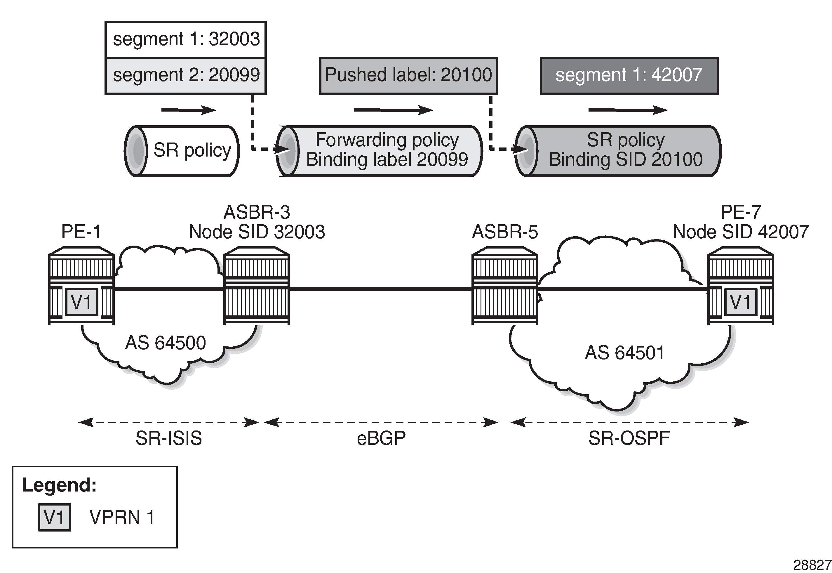
An SR policy on PE-1 pushes two labels: label 32003 from the SRGB for segment routing to SID 32003 of ASBR-3, and label 20099 from the SRLB corresponding to the binding label of the MPLS forwarding policy to be used in ASBR-3. In ASBR-3, these labels are popped and the MPLS forwarding policy is applied. This MPLS forwarding policy forwards the packet to ASBR-5 and pushes a binding label 20100 from the SRLB on ASBR-5, which identifies the SR policy to be used on ASBR-5. In ASBR-5, label 20100 is popped and an SR policy with binding SID 20100 is applied. This SR policy pushes label 42007, which is the SID of PE-7.
Configuration
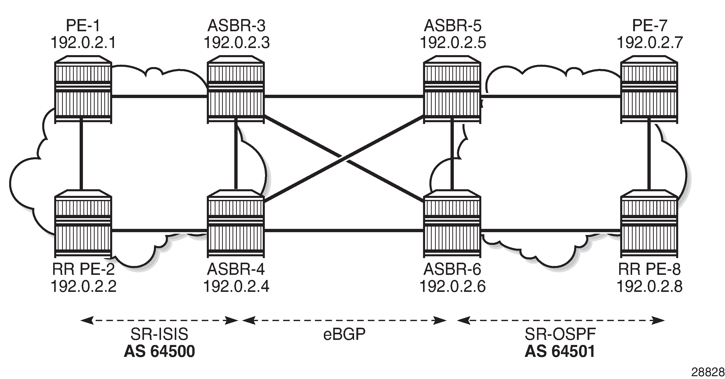
Example topology shows the example topology with four routers in AS 64500 and four routers in AS 64501. SR-ISIS is configured in AS 64500, while SR-OSPF is configured in AS 64501. The SR policies are configured within the ASs, whereas the MPLS forwarding policies are used to set up tunnels between the ASBRs.
The initial configuration includes:
-
Cards, MDAs, ports
-
Router interfaces
-
IS-IS as IGP between the routers in AS 64500; OSPF between the routers in AS 64501
Segment routing
SR-ISIS is configured in AS 64500. The following SR-ISIS configuration on PE-1 shows that the prefix SIDs are taken from the SRGB, which uses labels from 32000 to 32999, and the scope of the router capability advertisement is the area. The system interface has SID index 1, so the node SID label will be start label + index = 32000 + 1 = 32001.
The SRGB block does not need to have the same start value and end value on each router in the AS, but it must have the same size, that is, the same number of labels in the SRGB.
# on PE-1:
configure {
    router "Base" {
        autonomous-system 64500
        mpls-labels {
            sr-labels {
                start 32000
                end 32999   # SRGB block definition AS 64500
            }
        }
        isis 0 {            # IS-IS in the AS 64500; OSPF in ASs 64501
            admin-state enable
            advertise-router-capability area
            level-capability 2
            traffic-engineering true
            area-address [49.0001]
            segment-routing {
                admin-state enable
                prefix-sid-range {
                    global
                }
            }
            interface "int-PE-1-ASBR-3" {
                interface-type point-to-point
            }
            interface "int-PE-1-PE-2" {
                interface-type point-to-point
            }
            interface "system" {
                ipv4-node-sid {
                    index 1
                }
            }
        }
    }
}
The IS-IS configuration is similar on the other routers in AS 64500; the node SID index is different. On the routers in AS 64501, SR-OSPF is configured instead. The SR-OSPF configuration on PE-7 is as follows:
# on PE-7:
configure {
    router "Base" {
        autonomous-system 64501
        mpls-labels {
            sr-labels {
                start 42000
                end 42999            # SRGB block definition AS 64501
            }
        }
        ospf 0 {
            admin-state enable
            advertise-router-capability area
            traffic-engineering true
            segment-routing {
                admin-state enable
                prefix-sid-range {
                    global
                }
            }
            area 0.0.0.0 {
                interface "int-PE-7-ASBR-5" {
                    interface-type point-to-point
                }
                interface "int-PE-7-PE-8" {
                    interface-type point-to-point
                }
                interface "system" {
                    node-sid {
                        index 7
                    }
                }
            }
        }
    }
}
The OSPF configuration is similar on the other routers in AS 64501; the node SID index is different.
Inter-AS VPRN Model C
The configuration of inter-AS Model C VPRNs is described in the "Inter-AS VPRN Model C" chapter in the Layer 3 Services volume of 7450 ESS, 7750 SR, and 7950 XRS Advanced Configuration Guide — Book II. PE-2 acts as the Route Reflector (RR) for the "iBGP_grp" group in AS 64500; in AS 64501, PE-8 acts as the RR. Between AS 64500 and AS 64501, eBGP is configured on the ASBRs.
The RR addresses need to be advertised between the ASs. This can be done using IPv4 or labeled IPv4 (with next-hop resolution enabled). No other PE system addresses need to be advertised.
On PE-1, the system IP address 192.0.2.1/32 need not be exported, because no recursive lookup is required. Instead, the VPRN will be configured with auto-bind to the SR policy and the SR policy tunnel can resolve the next-hop of the VPN-IPv4 route. The following configuration shows the BGP configuration for address family VPN-IPv4 on PE-1:
# on PE-1:
configure {
    router "Base" {
        bgp {
            split-horizon true
            group "iBGP_grp" {
                type internal
                family {
                    vpn-ipv4 true
                }
            }
            neighbor "192.0.2.2" {
                group "iBGP_grp"
            }
        }
    }
}
On the ASBRs, BGP is configured for the labeled IPv4 address family only. On ASBR-3 and ASBR-4, the BGP next-hop for the labeled IPv4 address family can be resolved using SR-ISIS within AS 64500; on ASBR-5 and ASBR-6, the next-hop can be resolved using SR-OSPF within AS 64501. The forwarding between the ASBRs is based on label-binding MPLS forwarding policies. On ASBR-3, BGP is configured as follows:
# on ASBR-3:
configure {
    router "Base" {
        bgp {
            split-horizon true
            next-hop-resolution {
                labeled-routes {
                    transport-tunnel {
                        family label-ipv4 {
                            resolution-filter {
                                sr-isis true
                            }
                        }
                    }
                }
            }
            group "eBGP_grp" {
                peer-as 64501
                advertise-inactive true
                family {
                    label-ipv4 true
                }
                local-as {
                    as-number 64500
                }
            }
            group "iBGP_grp" {
                type internal
                family {
                    label-ipv4 true
                }
            }
            neighbor "192.0.2.2" {
                group "iBGP_grp"
            }
            neighbor "192.168.35.2" {
                group "eBGP_grp"
            }
            neighbor "192.168.36.2" {
                group "eBGP_grp"
            }
        }
    }
}
PE-2 is RR in AS 64500 and has a VPN-IPv4 session with PE-1 and labeled IPv4 sessions with both ASBR-3 and ASBR-4. The BGP next-hop for the labeled IPv4 family can be resolved using SR-ISIS. Between the RRs PE-2 and PE-8, a multi-hop eBGP session is established for the VPN-IPv4 address family. The BGP configuration on PE-2 is as follows:
# on PE-2:
configure {
    router "Base" {
        bgp {
            split-horizon true
            next-hop-resolution {
                labeled-routes {
                    transport-tunnel {
                        family label-ipv4 {
                            resolution-filter {
                                sr-isis true
                            }
                        }
                    }
                }
            }
            group "eBGP_grp" {
                multihop 10
                type external
                peer-as 64501
                local-address 192.0.2.2
                family {
                    vpn-ipv4 true
                }
                local-as {
                    as-number 64500
                }
            }
            group "iBGP_grp" {
                type internal
                advertise-inactive true
                cluster {
                    cluster-id 192.0.2.2    # PE-2 is RR in AS64500
                }
            }
            neighbor "192.0.2.1" {
                group "iBGP_grp"
                family {
                    vpn-ipv4 true
                }
            }
            neighbor "192.0.2.3" {
                group "iBGP_grp"
                family {
                    label-ipv4 true
                }
                export {
                    policy ["sysPE_pol"]
                }
            }
            neighbor "192.0.2.4" {
                group "iBGP_grp"
                family {
                    label-ipv4 true
                }
                export {
                    policy ["sysPE_pol"]
                }
            }
            neighbor "192.0.2.8" {            # set up multihop session to remote RR
                group "eBGP_grp"
            }
        }
    }
}
For this example, SR policies are used within an AS to resolve VPN-IPv4 next-hops using auto-bind-tunnel, whereas MPLS forwarding policies are used between ASs, on the ASBRs. However, SR policies can include a segment with a binding label value that identifies an MPLS forwarding policy defined in one of the local next-hop ASBRs (ASBR-3 or ASBR-4). In addition, MPLS forwarding policies can push a label identifying a BSID in an SR policy defined at the remote next-hop ASBR (ASBR-5 or ASBR-6).
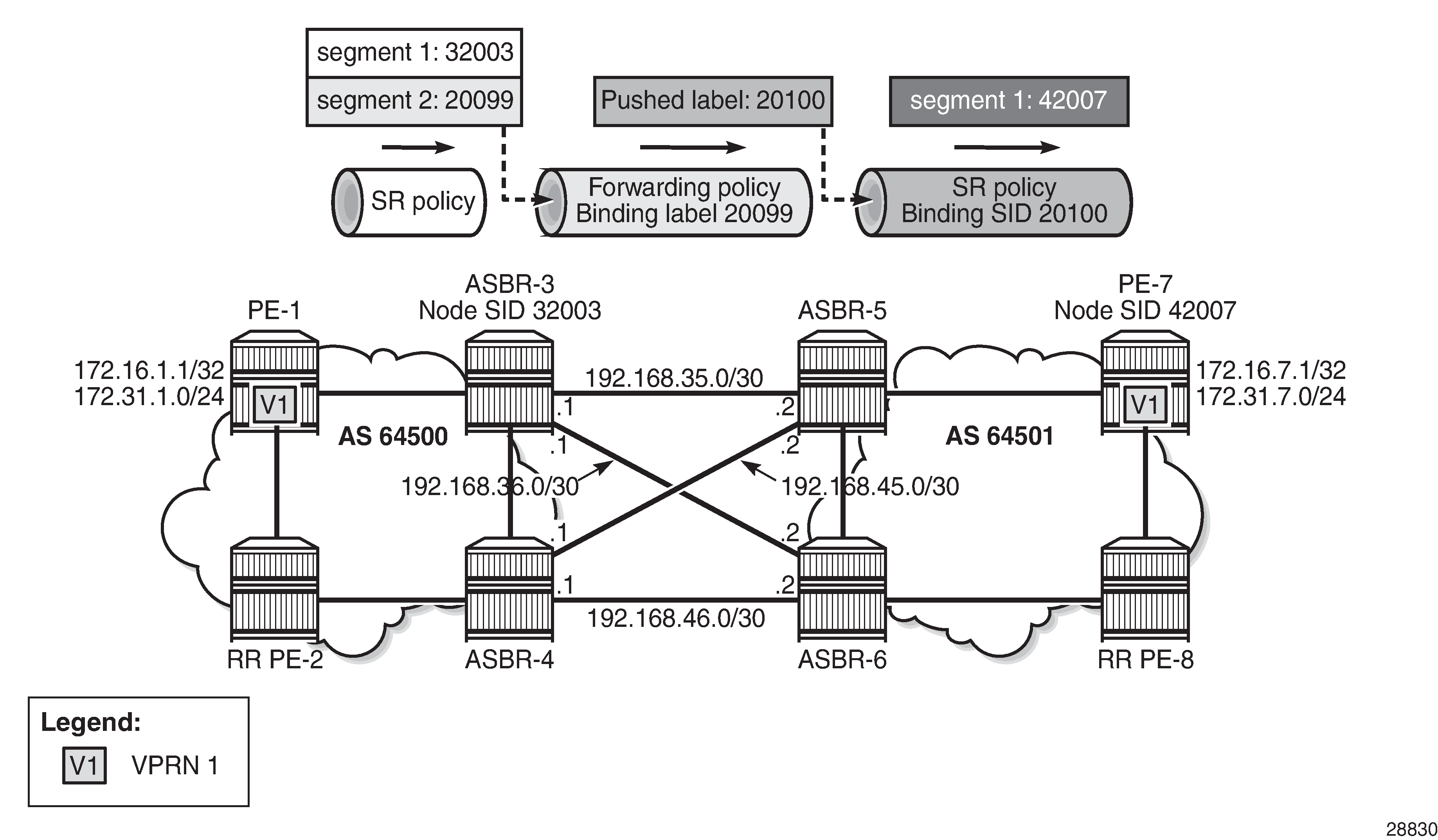
Inter-AS VPRN using MPLS forwarding policy and SR policies: Traffic to PE-7 shows the example topology for an inter-AS VPRN Model C using MPLS forwarding policies and SR policies. For traffic from VPRN 1 on PE-1 to VPRN 1 on PE-7, PE-1 pushes two labels: segment 1 has label 32003, which is the node SID of ASBR-3, and label 20099, which is the binding label of an MPLS forwarding policy defined on ASBR-3. This MPLS forwarding policy on ASBR-3 pops incoming label 20099 and pushes label 20100, which corresponds to the BSID of an SR policy defined on ASBR-5 and ASBR-6. This SR policy pops incoming label 20100 and pushes label 42007, which is the node SID of PE-7.
SR policies -like MPLS forwarding policies- use labels from an SRLB, which is a pool of labels defined as follows:
# on PE-1:
configure {
    router "Base" {
        mpls-labels {
            reserved-label-block "SRLB1" {
                start-label 20000
                end-label 21999
            }
        }
    }
}
SR policies contain MPLS labels in a segment list that instantiates SR-TE LSPs to a network endpoint. This appears in the tunnel table as an SR policy tunnel. On PE-1, the following SR policy-with endpoint 192.0.2.7 in a remote AS-is configured with one segment list including two segments:
-
segment 1 contains label 32003 referencing the node SID of ASBR-3.
-
segment 2 contains label 20099 referencing the binding label that matches the MPLS forwarding policy used at ASBR-3.
There are two ways to steer a set of flows into an SR policy: either based on the BSID value or based on a match of color and endpoint.
In this case, for a VPRN with auto-bind-tunnel, the payload prefix (VPN-IPv4 route prefix) must contain a color community value that matches the color value of the SR-policy route, and the prefix BGP next-hop must also match the endpoint value of the SR-policy route.
In addition, the reserved label block SRLB1 must be referenced within the SR policy context because the configured BSID (20000) is checked against this label block.
# on PE-1:
configure {
    router "Base" {
        segment-routing {
            sr-policies {
                admin-state enable
                reserved-label-block "SRLB1"
                static-policy "SR-static-policy-EP7" {
                    admin-state enable
                    color 100
                    endpoint 192.0.2.7
                    head-end local
                    binding-sid 20000
                    distinguisher 64500
                    segment-list 1 {
                        admin-state enable
                        segment 1 {
                            mpls-label 32003    # node SID of ASBR-3
                        }
                        segment 2 {
                            mpls-label 20099    # binding label of fwd-policy
                        }
                    }
                }
            }
        }
    }
}
On the ASBRs, MPLS forwarding policies are configured. Like SR policies (using BSID), the binding label is taken from reserved label block SRLB1, which is a pool of labels defined as follows:
# on ASBR-3:
configure {
    router "Base" {
        mpls-labels {
            reserved-label-block "SRLB1" {
                start-label 20000
                end-label 21999
            }
        }
    }
}
The reserved label block SRLB1 must be referenced within the MPLS forwarding policy context on each ASBR. The following MPLS forwarding policy is configured on ASBR-3 with binding label 20099, which maps to the segment 2 label defined in the SR policy on PE-1. The resolution type is set to direct, meaning that the next-hops are locally attached interface IP addresses. The primary next-hop 192.168.35.2 is on ASBR-5 and the backup next-hop 192.168.36.2 is on ASBR-6.
Within the MPLS forwarding policy on ASBR-3, the pushed label 20100 matches the BSID identifying the SR policy at the peer ASBRs (PE-5 and PE-6). In the MPLS forwarding policy on ASBR3, both the primary and backup next-hops are configured with the same pushed label 20100:
# on ASBR-3:
configure {
    router "Base" {
        mpls {
            admin-state enable
            forwarding-policies {
                admin-state enable
                reserved-label-block "SRLB1"
                forwarding-policy "SLR-ILM-pushed-label" {
                    admin-state enable
                    binding-label 20099
                    revert-timer 5
                    next-hop-group 1 {
                        admin-state enable
                        resolution-type direct
                        primary-next-hop {
                            next-hop 192.168.35.2
                            pushed-labels 1 {
                                label 20100
                            }
                        }
                        backup-next-hop {
                            next-hop 192.168.36.2
                            pushed-labels 1 {
                                label 20100
                            }
                        }
                    }
                }
            }
        }
    }
}
On ASBR-5 and ASBR-6, the following SR policy with endpoint PE-7 and binding SID 20100 only contains one segment toward the node SID of PE-7:
# on ASBR-5:
configure {
    router "Base" {
        segment-routing {
            sr-policies {
                admin-state enable
                reserved-label-block "SRLB1"
                static-policy "SR-static-policy-EP7" {
                    admin-state enable
                    color 100
                    endpoint 192.0.2.7
                    head-end local
                    binding-sid 20100
                    distinguisher 64501
                    segment-list 1 {
                        admin-state enable
                        segment 1 {
                            mpls-label 42007    # node SID of PE-7
                        }
                    }
                }
            }
        }
    }
}
In the opposite direction, the configuration is similar. Inter-AS VPRN using MPLS forwarding policy and SR policies: Traffic to PE-1 shows the labels used for traffic from PE-7 to PE-1.
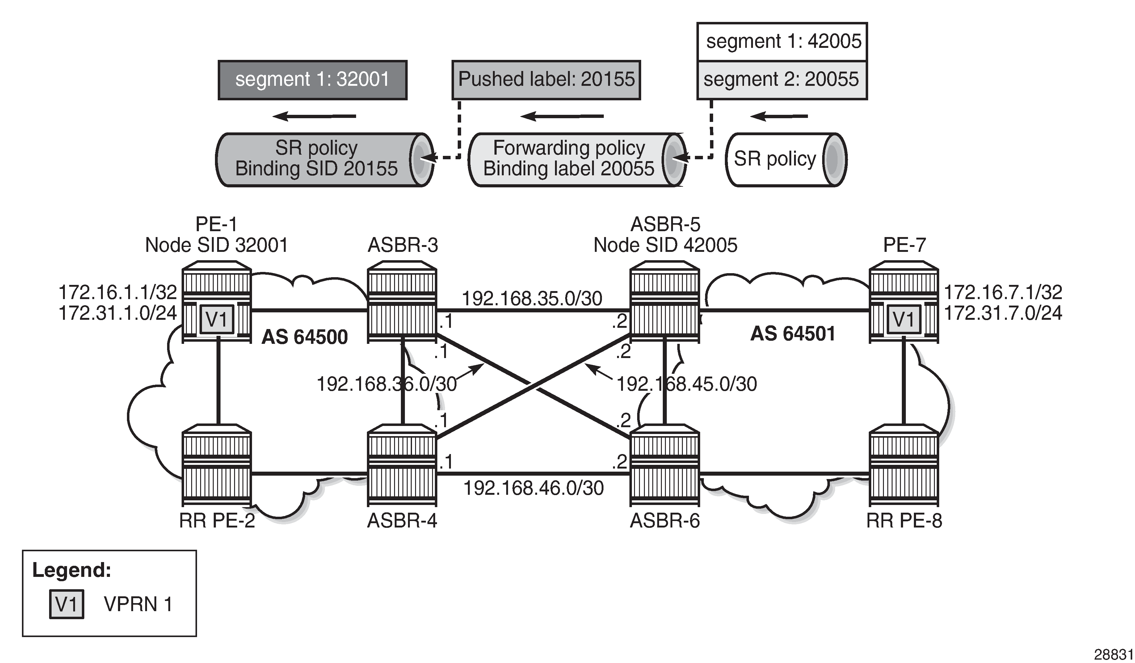
On PE-7, an SR policy is created with endpoint 192.0.2.1 and a segment list with two segments: segment 1 contains label 42005, which is the node SID of ASBR-5, and segment 2 contains label 20055 identifying the binding label in the MPLS forwarding policy at ASBR-5. The configured SR policy color is 100, so this applies for VPN-IPv4 routes with color extended community color:00:100.
# on PE-7:
configure {
    router "Base" {
        segment-routing {
            sr-policies {
                admin-state enable
                reserved-label-block "SRLB1"
                static-policy "SR-static-policy-EP1" {
                    admin-state enable
                    color 100
                    endpoint 192.0.2.1
                    head-end local
                    binding-sid 20001
                    distinguisher 64501
                    segment-list 1 {
                        admin-state enable
                        segment 1 {
                            mpls-label 42005    # node SID of ASBR-5
                        }
                        segment 2 {
                            mpls-label 20055    # binding label of fwd-policy
                        }
                    }
                }
            }
        }
    }
}
On ASBR-5, both labels (42005 and 20055) are popped and the MPLS forwarding policy with binding label 20055 pushes label 20155 to the primary and backup next-hops. The configuration is as follows:
# on ASBR-5:
configure {
    router "Base" {
        mpls {
            admin-state enable
            forwarding-policies {
                admin-state enable
                reserved-label-block "SRLB1"
                forwarding-policy "SLR-ILM-pushed-label" {
                    admin-state enable
                    binding-label 20055
                    revert-timer 5
                    next-hop-group 1 {
                        admin-state enable
                        resolution-type direct
                        primary-next-hop {
                            next-hop 192.168.35.1
                            pushed-labels 1 {
                                label 20155
                            }
                        }
                        backup-next-hop {
                            next-hop 192.168.45.1
                            pushed-labels 1 {
                                label 20155
                            }
                        }
                    }
                }
            }
        }
    }
}
On ASBR-3 and ASBR-4, an SR policy with BSID 20155 is configured. The segment list only contains one segment, which is the node SID of PE-1.
# on ASBR-3:
configure {
    router "Base" {
        segment-routing {
            sr-policies {
                admin-state enable
                reserved-label-block "SRLB1"
                static-policy "SR-static-policy-EP1" {
                    admin-state enable
                    color 100
                    endpoint 192.0.2.1
                    head-end local
                    binding-sid 20155
                    distinguisher 64500
                    segment-list 1 {
                        admin-state enable
                        segment 1 {
                            mpls-label 32001    # node SID of PE-1
                        }
                    }
                }
            }
        }
    }
}
On PE-1, VPRN 1 is configured with two loopback interfaces to test the traffic, as follows. The tunnel resolution filter within the service is set to sr-policy, configured explicitly. The configuration of VPRN 1 on PE-7 is similar, also with two loopback interfaces for test purposes: 17.16.7.1/32 and 172.31.7.1/24.
# on PE-1:
configure {
    service {
        vprn "VPRN 1" {
            admin-state enable
            service-id 1
            customer "1"
            bgp-ipvpn {
                mpls {
                    admin-state enable
                    route-distinguisher "192.0.2.1:1"
                    vrf-target {
                        import-community "target:64501:1"
                        export-community "target:64500:1"
                    }
                    auto-bind-tunnel {
                        resolution filter
                        resolution-filter {
                            sr-policy true
                        }
                    }
                }
            }
            interface "lo1" {
                loopback true
                ipv4 {
                    primary {
                        address 172.31.1.1
                        prefix-length 24
                    }
                }
            }
            interface "system" {
                loopback true
                ipv4 {
                    primary {
                        address 172.16.1.1
                        prefix-length 32
                    }
                }
            }
        }
    }
}
The following tunnel table show command on PE-1 returns one tunnel toward PE-7: an SR policy tunnel with color 100.
[/]
A:admin@PE-1# show router tunnel-table 192.0.2.7

===============================================================================
IPv4 Tunnel Table (Router: Base)
===============================================================================
Destination           Owner     Encap TunnelId  Pref   Nexthop        Metric
   Color
-------------------------------------------------------------------------------
192.0.2.7/32          sr-policy MPLS  917506    14     192.0.2.3      0
   100
-------------------------------------------------------------------------------
Flags: B = BGP or MPLS backup hop available
       L = Loop-Free Alternate (LFA) hop available
       E = Inactive best-external BGP route
       k = RIB-API or Forwarding Policy backup hop
===============================================================================
The following command shows that the SR policy tunnel with tunnel ID 917506 has next-hop 192.0.2.3 and label 20099, which matches the binding label value of the configured MPLS forwarding policy at next-hop ASBR-3.
[/]
A:admin@PE-1# show router fp-tunnel-table 1

===============================================================================
IPv4 Tunnel Table Display

Legend:
label stack is ordered from bottom-most to top-most
B - FRR Backup
===============================================================================
Destination                                  Protocol            Tunnel-ID
  Lbl/SID
    NextHop                                                      Intf/Tunnel
  Lbl/SID (backup)
    NextHop   (backup)
-------------------------------------------------------------------------------
192.0.2.2/32                                 SR-ISIS-0            524290
  32002
    192.168.12.2                                                  1/1/2:1000
192.0.2.3/32                                 SR-ISIS-0            524292
  32003
    192.168.13.2                                                  1/1/1:1000
192.0.2.4/32                                 SR-ISIS-0            524293
  32004
    192.168.12.2                                                  1/1/2:1000
192.0.2.7/32                                 SR-Policy            917506
  20099
    192.0.2.3                                                     SR
192.168.12.2/32                              SR                   524289
  3
    192.168.12.2                                                  1/1/2:1000
192.168.13.2/32                              SR                   524291
  3
    192.168.13.2                                                  1/1/1:1000
-------------------------------------------------------------------------------
Total Entries : 6
-------------------------------------------------------------------------------
===============================================================================
However, on PE-1, the received BGP-VPN routes are not used, as follows:
[/]
A:admin@PE-1# show router bgp routes vpn-ipv4
===============================================================================
 BGP Router ID:192.0.2.1        AS:64500       Local AS:64500
===============================================================================
 Legend -
 Status codes  : u - used, s - suppressed, h - history, d - decayed, * - valid
                 l - leaked, x - stale, > - best, b - backup, p - purge
 Origin codes  : i - IGP, e - EGP, ? - incomplete

===============================================================================
BGP VPN-IPv4 Routes
===============================================================================
Flag  Network                                            LocalPref   MED
      Nexthop (Router)                                   Path-Id     IGP Cost
      As-Path                                                        Label
-------------------------------------------------------------------------------
*>i   192.0.2.7:1:172.16.7.1/32                          100         None
      192.0.2.7                                          None        0
      64501                                                          524286
*>i   192.0.2.7:1:172.31.7.0/24                          100         None
      192.0.2.7                                          None        0
      64501                                                          524286
-------------------------------------------------------------------------------
Routes : 2
===============================================================================
Therefore, the following route table for VPRN 1 does not include any route toward VPRN 1 on PE-7:
[/]
A:admin@PE-1# show router 1 route-table

===============================================================================
Route Table (Service: 1)
===============================================================================
Dest Prefix[Flags]                            Type    Proto     Age        Pref
      Next Hop[Interface Name]                                    Metric
-------------------------------------------------------------------------------
172.16.1.1/32                                 Local   Local     00h46m33s  0
       system                                                       0
172.31.1.0/24                                 Local   Local     00h46m33s  0
       lo1                                                          0
-------------------------------------------------------------------------------
No. of Routes: 2
Flags: n = Number of times nexthop is repeated
       B = BGP backup route available
       L = LFA nexthop available
       S = Sticky ECMP requested
===============================================================================
As stated earlier, the following two conditions are required to ensure that the traffic flow from VPRN 1 is steered by the SR policy on PE-1:
-
the BGP payload prefix next-hop must match the endpoint value in the SR policy
-
the BGP payload prefix must have a color extended community, matching the color value in the SR policy
To match the second condition, the following BGP policy exports the prefixes of VPRN 1 and adds color extended community "color:00:100" and extended community "target:64500:1" to the VPN-IPv4 routes.
# on PE-1:
configure {
    policy-options {
        community "Color100_com" {
            member "color:00:100" { }
        }
        community "VRF1-export_com" {
            member "target:64500:1" { }
        }
        prefix-list "VRF1-prefixes" {
            prefix 172.16.1.1/32 type exact {
            }
            prefix 172.31.1.0/24 type exact {
            }
        }
        policy-statement "Color100_VRF1_pol" {
            entry 10 {
                from {
                    prefix-list ["VRF1-prefixes"]
                }
                to {
                    protocol {
                        name [bgp-vpn]
                    }
                }
                action {
                    action-type accept
                    community {
                        add ["VRF1-export_com" "Color100_com"]
                    }
                }
            }
        }
    }
}
This policy is applied as a VRF export policy in VPRN 1, as follows:
# on PE-1:
configure {
    service {
        vprn "VPRN 1" {
            bgp-ipvpn {
                mpls {
                    vrf-export {
                        policy ["Color100_VRF1_pol"]
                    }
                }
            }
        }
    }
}
The BGP update message shows that the VPN-IPv4 routes contain both extended communities:
1 2021/09/20 14:31:41.065 UTC MINOR: DEBUG #2001 Base Peer 1: 192.0.2.2
"Peer 1: 192.0.2.2: UPDATE
Peer 1: 192.0.2.2 - Send BGP UPDATE:
    Withdrawn Length = 0
    Total Path Attr Length = 85
    Flag: 0x90 Type: 14 Len: 48 Multiprotocol Reachable NLRI:
        Address Family VPN_IPV4
        NextHop len 12 NextHop 192.0.2.1
        172.16.1.1/32 RD 192.0.2.1:1 Label 524287 (Raw label 0x7ffff1)
        172.31.1.0/24 RD 192.0.2.1:1 Label 524287 (Raw label 0x7ffff1)
    Flag: 0x40 Type: 1 Len: 1 Origin: 0
    Flag: 0x40 Type: 2 Len: 0 AS Path:
    Flag: 0x40 Type: 5 Len: 4 Local Preference: 100
    Flag: 0xc0 Type: 16 Len: 16 Extended Community:
        target:64500:1
        color:00:100
"
The VPN-IPv4 routes are using the SR policy tunnel to PE-7, as follows:
[/]
A:admin@PE-1# show router bgp next-hop vpn-ipv4
===============================================================================
 BGP Router ID:192.0.2.1        AS:64500       Local AS:64500
===============================================================================

===============================================================================
BGP VPN Next Hop
===============================================================================
VPN Next Hop                                                Owner
   Autobind                                        FibProg  Reason
   Labels                                          FlexAlgo Metric
   Admin-tag-policy (strict-tunnel-tagging)
-------------------------------------------------------------------------------
192.0.2.7                                                   SR-POLICY
   bgp sr-policy                                      Y
   --                                              --       0
   -- (-)
-------------------------------------------------------------------------------
Next Hops : 1
===============================================================================
In the route table of VPRN 1 on PE-1, routes to VPRN 1 on PE-7 use the SR policy tunnel toward PE-7, as follows:
[/]
A:admin@PE-1# show router 1 route-table

===============================================================================
Route Table (Service: 1)
===============================================================================
Dest Prefix[Flags]                            Type    Proto     Age        Pref
      Next Hop[Interface Name]                                    Metric
-------------------------------------------------------------------------------
172.16.1.1/32                                 Local   Local     01h12m28s  0
       system                                                       0
172.16.7.1/32                                 Remote  BGP VPN   00h17m00s  170
       192.0.2.7 (tunneled:SR-Policy:917506)                        0
172.31.1.0/24                                 Local   Local     01h12m28s  0
       lo1                                                          0
172.31.7.0/24                                 Remote  BGP VPN   00h17m00s  170
       192.0.2.7 (tunneled:SR-Policy:917506)                        0
-------------------------------------------------------------------------------
No. of Routes: 4
Flags: n = Number of times nexthop is repeated
       B = BGP backup route available
       L = LFA nexthop available
       S = Sticky ECMP requested
===============================================================================
Color-only steering can be achieved without the need to match the BGP next-hop endpoint. This is done by setting the "color-only" (CO) bits, which are the two highest order bits of the color extended community. When set to "10" or "01" instead of "00", the endpoint value in the SR policy can be set to "0.0.0.0". In this case, only the color value is checked as a single condition to steer traffic flows using the SR policy.
Show and Debug commands
The following command shows the SR policies on PE-1, with the segment list, color, endpoint address, and so on:
[/]
A:admin@PE-1# show router segment-routing sr-policies all

===============================================================================
SR-Policies Path
===============================================================================
-------------------------------------------------------------------------------
Active          : Yes                   Owner           : static
Color           : 100
Head            : 0.0.0.0               Endpoint Addr   : 192.0.2.7
RD              : 64500                 Preference      : 100
BSID            : 20000
TunnelId        : 917506                Age             : 218
Origin ASN      : 0                     Origin          : 0.0.0.0
NumReEval       : 0                     ReEvalReason    : none
NumActPathChange: 0                     Last Change     : 09/20/2021 14:18:28
Maintenance Policy: N/A

Path Segment Lists:
Segment-List    : 1                     Weight          : 1
S-BFD State     : Down                  S-BFD Transitio*: 0
Num Segments    : 2                     Last Change     : 09/20/2021 13:31:51
  Seg 1 Label   : 32003                 State           : resolved-up
  Seg 2 Label   : 20099                 State           : N/A

===============================================================================
* indicates that the corresponding row element may have been truncated.
For each combination of color and endpoint, the SR database must validate each segment list / candidate path, and choose one to be the active path. The most important checks are:
-
The configured BSID is part of the SRLB. In this example, 20000 is part of the SRLB1 block on PE-1, which ranges from 20000 to 21999. The BSID is used uniquely by this policy.
-
The first segment of each segment list is resolved to a set of one or more next-hops. This means matching an SR-ISIS or SR-OSPF node SID, matching an SR-ISIS or SR-OSPF adjacency SID, or matching an SR-ISIS or SR-OSPF adjacency-set SID. In this example, on PE-1, label 32003 resolves to the SR-ISIS node SID of ASBR-3.
The following command shows the MPLS forwarding policy on ASBR-3, including the binding label, NHG, and pushed labels. If, for example, the reserved label block was not defined or not referenced by the MPLS forwarding policy, the validation would fail and the MPLS forwarding policy would remain operationally down.
[/]
A:admin@ASBR-3# show router mpls forwarding-policies forwarding-policy detail

===============================================================================
Forwarding Policy (Detail)
===============================================================================
-------------------------------------------------------------------------------
Policy : SLR-ILM-pushed-label
-------------------------------------------------------------------------------
Admin State      : Up                   Oper State       : Up
Binding Label    : 20099                Preference       : 255
Revert Timer     : 5 sec
Last Change      : 09/20/2021 14:19:00
Ingress Stats    : Disabled
Metric           : 0                    Tunnel Table Pref: 255
Endpoint Address : N/A

Next-hop Group   : 1
Admin State      : Up                   Oper State       : Up
Resolution Type  : direct               Load Balancing Wt: 0
Last Change      : 09/20/2021 14:19:00
Primary
NH Address       : 192.168.35.2
Oper State       : Up                   Last Change      : 09/20/2021 14:19:00
Pushed Labels    : 20100
Backup
NH Address       : 192.168.36.2
Oper State       : Up                   Last Change      : 09/20/2021 14:19:00
Pushed Labels    : 20100
===============================================================================
The following command shows the details of the MPLS binding label forwarding policy:
[/]
A:admin@ASBR-3# show router mpls forwarding-policies binding-label detail

===============================================================================
Binding Label (Detail)
===============================================================================
Label          : 20099                  Preference     : 255
Policy Name    : SLR-ILM-pushed-label
Oper State     : Up                     OperDownReason : notApplicable
Up Time        : 09/20/2021 14:07:03    NumNextHopGrps : 1
Ingress Stats  : Disabled               IngrOperState  : Down
Egress Stats   : Disabled               EgrOperState   : Down
Revert Timer   : 5
Retry Count    : 0                      Next Retry In  : 0

Next-hop Group : 1                      Resolution Type: direct
Oper State     : Up                     OperDownReason : notApplicable
Num Revert     : 0                      Num Failover   : 0
Next Revert In : 0
Primary nexthop: 192.168.35.2
Resolved       : True                   NHopDownReason : notApplicable
EgrOperState   : Down
Pushed Labels  : 20100
Backup nexthop : 192.168.36.2
Resolved       : True                   NHopDownReason : notApplicable
EgrOperState   : Down
Pushed Labels  : 20100
-------------------------------------------------------------------------------
===============================================================================
The following tools command on ASBR-3 shows that the MPLS forwarding policy is validated and the ILM is programmed with the binding label value. The output also shows which router interfaces are used toward the configured next-hops and what label stack is pushed.
[/]
A:admin@ASBR-3# tools dump router mpls forwarding-policies binding-label 20099

 Db Mgr flags 0x80 ilmStatsFailCnt 0
---------------------------------------------------------------------------
 dbOwner FWD PLCY routeOwner 48 rsvdBlkId 2 flags 0x3 numPolicies 1 numInstalled 1
---------------------------------------------------------------------------

 Label DB 20099
 dbFlags 0xd PathCount 1 srTunnelId 851970 ilmStatsIdx[MGMT] 0x0 ilmStatsIdx[API] 0x0
LABEL RESERVED:  PROGRAMMED
 Path bitmap 0
 Label Retry time left : 0 retrycount : 0,  SR Retry time left : 0 SR retrycount : 0

 Best Db Path owner 0 path name vrId:1, dbOwner:0, pathName:SLR-ILM-pushed-label Last Modified 09/20/2021 14:19:00 Up Time 0d 00:33:31
 Preference 255 flags 0x245 Status FWDPLCY_ERR_NA SR status SR_ERR_OK
 PrimResolved NH's 1 BkupResolved NH's 1
 NHGroup 1
 flags 0x3bf9 : weight 0 normalized weight 0
 Revert timer 5 Time left 0 NumOfReverts 0

 Hold timer 0 Time left 0
DIRECT NH:  PRIM PGMED:  PRIM RESOLVED:  BKUP RESOLVED:  BKUP PGMED:
 primaryNH 192.168.35.2 egrStatsIdx 0x0 Status FWDPLCY_NHERR_NA
 Label Stack:20100 0
 Nexthop 1 192.168.35.2 outIf 3 globalIfIndex 2 globaIfInNHgrp 2
 PG ID 4
 PG ID 0
 backupNH 192.168.36.2 egrStatsIdx 0x0 Status FWDPLCY_NHERR_NA
 Label stack:20100 0
 Nexthop 1 192.168.36.2 outIf 4 globalIfIndex 3 globaIfInNHgrp 3
 PG ID 5
 PG ID 0

 ---------------------------------------------------------------------
Conclusion
MPLS forwarding policies provide the customization of next-hops as well as ECMP, weighted ECMP, Class-Based Forwarding, and backup support. MPLS forwarding policies can be combined with SR policies.