Parallel Adjacency Sets in Segment Routing
This chapter describes the Parallel Adjacency Sets in Segment Routing.
Topics in this chapter include:
Applicability
The information and configuration in this chapter are based on SR OS Release 21.7.R1. They apply for MD-CLI.
Overview
SR OS supports segment routing as described in RFC 8402, Segment Routing Architecture. In the remainder of this chapter, SR refers to "Segment Routing", unless specified otherwise. Product and release references, such as 7750 SR and SR OS, continue to refer to "Service Router".
SR provides operators the means to provision paths or tunnels, encoded as a sequential list of sub-paths or segments without requiring a dedicated signaling protocol, by advertising the identities of the segments across the SR domain using extensions to the link state Interior Gateway Protocols (IGPs), such as IS-IS and OSPF.
When defining source-routed traffic-engineered end-to-end SR paths, routing constraints such as loose and strict hops can be used to control the data path through a network; a node SID is used for a loose hop, and an adjacency SID is used for a strict hop. See the Segment Routing – Traffic Engineered Tunnels chapter for more information.
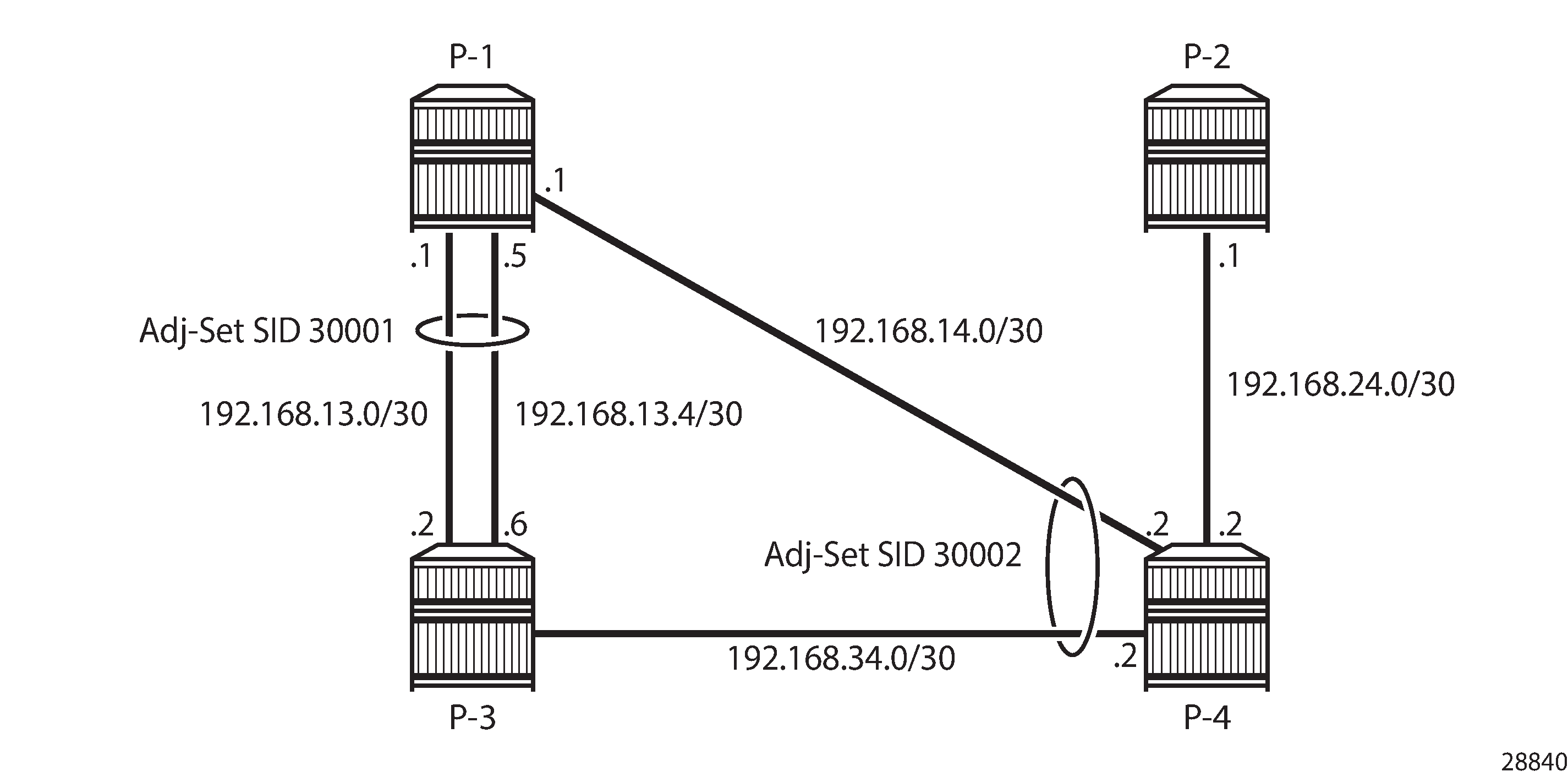
Parallel links between adjacent nodes can be grouped into adjacency sets, and a single adjacency set is identified using a locally significant adjacency set SID. Traffic can be load shared across the links in the set and is based on traffic flow identifiers; for example, source and destination IP addresses, and entropy label.
In Parallel and non-parallel adjacency sets, two adjacency sets are defined. A first adjacency set is defined on P-1 with adjacency set SID 30001. Two parallel links are available between P-1 and P-2, and by combining them into an adjacency set, traffic can be shared across both links. A second set is defined on P-4, with adjacency set SID 30002. However, the member links of that set are not terminated on the same router pair, so traffic cannot be shared.
Configuration
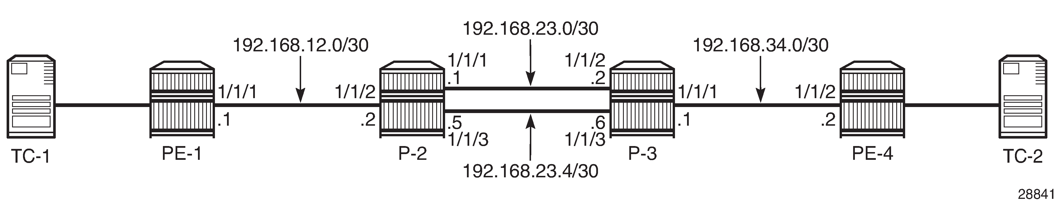
The topology used in this chapter is shown in Parallel adjacency set. All nodes are configured for SR and IS-IS level 2. If test center TC-1 is connected at PE-1 and test center TC-2 is connected at PE-4, traffic can be sent from TC-1 to TC-2 following the PE-1, P-2, P-3, PE-4 path. Two links are active between P-2 and P-3, and these links belong to the same adjacency set.
The initial configuration on the PE nodes includes the following:
-
Cards, MDAs, ports
-
Router interfaces
-
IS-IS
Segment routing configuration
In the topology from Parallel adjacency set, all nodes are configured with a common Segment Routing Global Block (SRGB), which is defined as follows:
configure {
    router "Base" {
        mpls-labels {
            sr-labels {
                start 20000
                end 20099
            }
        }
    }
}
In this example, prefix SID allocation is using global mode, and the node SIDs are defined by index on the system interfaces in the isis context, where PE-1, P-2, P-3, and PE-4 take the indices 1, 2, 3, and 4, respectively. The advertise-router-capability area command enables the IS-IS extensions so that the SID values are advertised throughout the SR domain. The configuration on PE-1 is as follows; the configuration on the other nodes is similar.
# on PE-1
configure {
    router "Base" {
        isis 0 {
            admin-state enable
            advertise-router-capability area
            level-capability 2
            traffic-engineering true
            area-address [49.0001]
            segment-routing {
                admin-state enable
                prefix-sid-range {
                    global
                }
            }
            interface "int-PE-1-P-2" {
                interface-type point-to-point
            }
            interface "system" {
                ipv4-node-sid {
                    index 1
                }
            }
        }
    }
}
With this configuration, each node floods the SIDs in link state packets (shown as "LSP") across the domain. For P-2, prefix 192.0.2.2 has index 2 in the SRGB. The adjacency SIDs 524285, 524286, and 524287 are taken from the dynamic range, as follows:
[/]
A:admin@P-2# show router isis database P-2.00-00 detail

===============================================================================
Rtr Base ISIS Instance 0 Database (detail)
===============================================================================

Displaying Level 1 database
-------------------------------------------------------------------------------
Level (1) LSP Count : 0

Displaying Level 2 database
-------------------------------------------------------------------------------
LSP ID    : P-2.00-00                                   Level     : L2
Sequence  : 0x3                    Checksum  : 0xeb4b   Lifetime  : 1103
Version   : 1                      Pkt Type  : 20       Pkt Ver   : 1
Attributes: L1L2                   Max Area  : 3        Alloc Len : 1492
SYS ID    : 1920.0000.2002         SysID Len : 6        Used Len  : 330

TLVs :
  Area Addresses:
    Area Address : (3) 49.0001
  Supp Protocols:
    Protocols     : IPv4
  IS-Hostname   : P-2
  Router ID   :
    Router ID   : 192.0.2.2
  Router Cap : 192.0.2.2, D:0, S:0
    TE Node Cap : B E M  P
    SR Cap: IPv4 MPLS-IPv6
       SRGB Base:20000, Range:100
    SR Alg: metric based SPF
    Node MSD Cap: BMI : 12 ERLD : 15
  IS Neighbors  :
    Virtual Flag  : 0
    Default Metric: (I) 10
    Delay Metric  : (I) 0
    Expense Metric: (I) 0
    Error Metric  : (I) 0
    Neighbor      : PE-1.00
  IS Neighbors  :
    Virtual Flag  : 0
    Default Metric: (I) 10
    Delay Metric  : (I) 0
    Expense Metric: (I) 0
    Error Metric  : (I) 0
    Neighbor      : P-3.00
  Internal Reach:
    Default Metric: (I) 10
    Delay Metric  : (I) 0
    Expense Metric: (I) 0
    Error Metric  : (I) 0
    IP Address    : 192.168.12.0
    IP Mask       : 255.255.255.252
    Default Metric: (I) 10
    Delay Metric  : (I) 0
    Expense Metric: (I) 0
    Error Metric  : (I) 0
    IP Address    : 192.168.23.0
    IP Mask       : 255.255.255.252
    Default Metric: (I) 0
    Delay Metric  : (I) 0
    Expense Metric: (I) 0
    Error Metric  : (I) 0
    IP Address    : 192.0.2.2
    IP Mask       : 255.255.255.255
    Default Metric: (I) 10
    Delay Metric  : (I) 0
    Expense Metric: (I) 0
    Error Metric  : (I) 0
    IP Address    : 192.168.23.4
    IP Mask       : 255.255.255.252
  I/F Addresses :
    I/F Address   : 192.168.23.1
    I/F Address   : 192.0.2.2
    I/F Address   : 192.168.12.2
    I/F Address   : 192.168.23.5
  TE IS Nbrs   :
    Nbr   : PE-1.00
    Default Metric  : 10
    Sub TLV Len     : 19
    IF Addr   : 192.168.12.2
    Nbr IP    : 192.168.12.1
    Adj-SID: Flags:v4VL Weight:0 Label:524287
  TE IS Nbrs   :
    Nbr   : P-3.00
    Default Metric  : 10
    Sub TLV Len     : 26
    IF Addr   : 192.168.23.1
    Nbr IP    : 192.168.23.2
    Adj-SID: Flags:v4VL Weight:0 Label:524286
    Adj-SID: Flags:v4VLSP Weight:0 Label:30000
  TE IS Nbrs   :
    Nbr   : P-3.00
    Default Metric  : 10
    Sub TLV Len     : 26
    IF Addr   : 192.168.23.5
    Nbr IP    : 192.168.23.6
    Adj-SID: Flags:v4VL Weight:0 Label:524285
    Adj-SID: Flags:v4VLSP Weight:0 Label:30000
  TE IP Reach   :
    Default Metric  : 10
    Control Info:    , prefLen 30
    Prefix   : 192.168.12.0
    Default Metric  : 10
    Control Info:    , prefLen 30
    Prefix   : 192.168.23.0
    Default Metric  : 0
    Control Info:   S, prefLen 32
    Prefix   : 192.0.2.2
    Sub TLV   :
      Prefix-SID Index:2, Algo:0, Flags:NnP
    Default Metric  : 10
    Control Info:    , prefLen 30
    Prefix   : 192.168.23.4

Level (2) LSP Count : 1
-------------------------------------------------------------------------------
Control Info     : D = Prefix Leaked Down
                   S = Sub-TLVs Present
Attribute Flags  : N = Node Flag
                   R = Re-advertisement Flag
                   X = External Prefix Flag
                   E = Entropy Label Capability (ELC) Flag
Adj-SID Flags    : v4/v6 = IPv4 or IPv6 Address-Family
                   B = Backup Flag
                   V = Adj-SID carries a value
                   L = value/index has local significance
                   S = Set of Adjacencies
                   P = Persistently allocated
Prefix-SID Flags : R = Re-advertisement Flag
                   N = Node-SID Flag
                   nP = no penultimate hop POP
                   E = Explicit-Null Flag
                   V = Prefix-SID carries a value
                   L = value/index has local significance
Lbl-Binding Flags: v4/v6 = IPv4 or IPv6 Address-Family
                   M = Mirror Context Flag
                   S = SID/Label Binding flooding
                   D = Prefix Leaked Down
                   A = Attached Flag
SABM-flags Flags:  R = RSVP-TE
                   S = SR-TE
                   F = LFA
                   X = FLEX-ALGO
FAD-flags Flags:   M = Prefix Metric
===============================================================================
Adjacency set configuration
Adjacency set SIDs are allocated from a reserved label block. Because the adjacency SIDs have a local significance only, the same block can be defined on each node. In this example, a different label block is defined on P-2 and P-3 respectively, as follows. The start-label and end-label values must be in the dynamic range.
# on P-2
configure {
    router "Base" {
        mpls-labels {
            reserved-label-block "adjset_block_on_P-2" {
                start-label 30000
                end-label 30099
            }
        }
    }
}

# on P-3
configure {
    router "Base" {
        mpls-labels {
            reserved-label-block "adjset_block_on_P-3" {
                start-label 40000
                end-label 40099
            }
        }
    }
}
This range is listed in the show router mpls-labels label-range command, as follows:
[/]
A:admin@P-2# show router mpls-labels label-range

===============================================================================
Label Ranges
===============================================================================
Label Type      Start Label End Label   Aging       Available   Total
-------------------------------------------------------------------------------
Static          32          18431       -           18400       18400
Dynamic         18432       524287      0           505653      505856
    Seg-Route   20000       20099       -           0           100

-------------------------------------------------------------------------------
Reserved Label Blocks
-------------------------------------------------------------------------------
Reserved Label                               Start       End         Total
Block Name                                   Label       Label
-------------------------------------------------------------------------------
adjset_block_on_P-2                          30000       30099       100
-------------------------------------------------------------------------------
No. of Reserved Label Blocks: 1
-------------------------------------------------------------------------------
===============================================================================
The reserved label block range is then defined as a Segment Routing Local Block (SRLB) in the segment-routing context. Label values for adjacency sets must be allocated from the SRLB; otherwise, an error is raised. The adjacency set is identified by number, and on P-2 adjacency set 1 has a SID label value of 30000. A similar configuration is used on P-3. If no SID label value is configured, the system will allocate a value from the SRLB range.
# on P-2
configure {
    router "Base" {
        isis 0 {
            segment-routing {
                admin-state enable
                srlb "adjset_block_on_P-2"
                adjacency-set 1 {
                    sid {
                        label 30000
                    }
                }
            }
        }
    }
}

# on P-3
configure {
    router "Base" {
        isis 0 {
            segment-routing {
                admin-state enable
                srlb "adjset_block_on_P-3"
                adjacency-set 1 {
                    sid {
                        label 40000
                    }
                }
            }
        }
    }
}
On P-2, the int-P-2-P-3-a and int-P-2-P-3-b interfaces have addresses 192.168.23.1/30 and 192.168.23.5/30, respectively, and these interfaces are included in adjacency set 1 by applying the adjacency set index to the individual interfaces, as follows. A similar configuration is present on P-3.
configure {
    router "Base" {
        isis 0 {
            interface "int-P-2-P-3-a" {
                interface-type point-to-point
                adjacency-set 1 { }
            }
            interface "int-P-2-P-3-b" {
                interface-type point-to-point
                adjacency-set 1 { }
            }
            interface "int-P-2-PE-1" {
                interface-type point-to-point
            }
            interface "system" {
                ipv4-node-sid {
                    index 2
                }
            }
        }
    }
}
With this configuration applied, IS-IS floods the adjacency set SID in the adjacency SID sub-TLV across the domain, as follows. The S flag indicates that this SID identifies an adjacency set; the P flag indicates that the SID value is persistent.
[/]
A:admin@P-2# show router isis database P-2.00-00 detail

===============================================================================
Rtr Base ISIS Instance 0 Database (detail)
===============================================================================

Displaying Level 1 database
-------------------------------------------------------------------------------
Level (1) LSP Count : 0

Displaying Level 2 database
-------------------------------------------------------------------------------
LSP ID    : P-2.00-00                                   Level     : L2
Sequence  : 0x3                    Checksum  : 0xeb4b   Lifetime  : 1103
Version   : 1                      Pkt Type  : 20       Pkt Ver   : 1
Attributes: L1L2                   Max Area  : 3        Alloc Len : 1492
SYS ID    : 1920.0000.2002         SysID Len : 6        Used Len  : 330

TLVs :
  Area Addresses:
    Area Address : (3) 49.0001
  Supp Protocols:
    Protocols     : IPv4
  IS-Hostname   : P-2
  Router ID   :
    Router ID   : 192.0.2.2
  Router Cap : 192.0.2.2, D:0, S:0
    TE Node Cap : B E M  P
    SR Cap: IPv4 MPLS-IPv6
       SRGB Base:20000, Range:100
    SR Alg: metric based SPF
    Node MSD Cap: BMI : 12 ERLD : 15
  IS Neighbors  :
    Virtual Flag  : 0
    Default Metric: (I) 10
    Delay Metric  : (I) 0
    Expense Metric: (I) 0
    Error Metric  : (I) 0
    Neighbor      : PE-1.00
  IS Neighbors  :
    Virtual Flag  : 0
    Default Metric: (I) 10
    Delay Metric  : (I) 0
    Expense Metric: (I) 0
    Error Metric  : (I) 0
    Neighbor      : P-3.00
  Internal Reach:
    Default Metric: (I) 10
    Delay Metric  : (I) 0
    Expense Metric: (I) 0
    Error Metric  : (I) 0
    IP Address    : 192.168.12.0
    IP Mask       : 255.255.255.252
    Default Metric: (I) 10
    Delay Metric  : (I) 0
    Expense Metric: (I) 0
    Error Metric  : (I) 0
    IP Address    : 192.168.23.0
    IP Mask       : 255.255.255.252
    Default Metric: (I) 0
    Delay Metric  : (I) 0
    Expense Metric: (I) 0
    Error Metric  : (I) 0
    IP Address    : 192.0.2.2
    IP Mask       : 255.255.255.255
    Default Metric: (I) 10
    Delay Metric  : (I) 0
    Expense Metric: (I) 0
    Error Metric  : (I) 0
    IP Address    : 192.168.23.4
    IP Mask       : 255.255.255.252
  I/F Addresses :
    I/F Address   : 192.168.23.1
    I/F Address   : 192.0.2.2
    I/F Address   : 192.168.12.2
    I/F Address   : 192.168.23.5
  TE IS Nbrs   :
    Nbr   : PE-1.00
    Default Metric  : 10
    Sub TLV Len     : 19
    IF Addr   : 192.168.12.2
    Nbr IP    : 192.168.12.1
    Adj-SID: Flags:v4VL Weight:0 Label:524287
  TE IS Nbrs   :
    Nbr   : P-3.00
    Default Metric  : 10
    Sub TLV Len     : 26
    IF Addr   : 192.168.23.1
    Nbr IP    : 192.168.23.2
    Adj-SID: Flags:v4VL Weight:0 Label:524286
    Adj-SID: Flags:v4VLSP Weight:0 Label:30000
  TE IS Nbrs   :
    Nbr   : P-3.00
    Default Metric  : 10
    Sub TLV Len     : 26
    IF Addr   : 192.168.23.5
    Nbr IP    : 192.168.23.6
    Adj-SID: Flags:v4VL Weight:0 Label:524285
    Adj-SID: Flags:v4VLSP Weight:0 Label:30000
  TE IP Reach   :
    Default Metric  : 10
    Control Info:    , prefLen 30
    Prefix   : 192.168.12.0
    Default Metric  : 10
    Control Info:    , prefLen 30
    Prefix   : 192.168.23.0
    Default Metric  : 0
    Control Info:   S, prefLen 32
    Prefix   : 192.0.2.2
    Sub TLV   :
      Prefix-SID Index:2, Algo:0, Flags:NnP
    Default Metric  : 10
    Control Info:    , prefLen 30
    Prefix   : 192.168.23.4

Level (2) LSP Count : 1
-------------------------------------------------------------------------------
Control Info     : D = Prefix Leaked Down
                   S = Sub-TLVs Present
Attribute Flags  : N = Node Flag
                   R = Re-advertisement Flag
                   X = External Prefix Flag
                   E = Entropy Label Capability (ELC) Flag
Adj-SID Flags    : v4/v6 = IPv4 or IPv6 Address-Family
                   B = Backup Flag
                   V = Adj-SID carries a value
                   L = value/index has local significance
                   S = Set of Adjacencies
                   P = Persistently allocated
Prefix-SID Flags : R = Re-advertisement Flag
                   N = Node-SID Flag
                   nP = no penultimate hop POP
                   E = Explicit-Null Flag
                   V = Prefix-SID carries a value
                   L = value/index has local significance
Lbl-Binding Flags: v4/v6 = IPv4 or IPv6 Address-Family
                   M = Mirror Context Flag
                   S = SID/Label Binding flooding
                   D = Prefix Leaked Down
                   A = Attached Flag
SABM-flags Flags:  R = RSVP-TE
                   S = SR-TE
                   F = LFA
                   X = FLEX-ALGO
FAD-flags Flags:   M = Prefix Metric
===============================================================================
SR traffic engineered label switched path configuration
For traffic from PE-1 to PE-4 to use the adjacency set between P-2 and P-3, a label switched path is required. This path can be defined using SR policies or using SR traffic engineered (SR-TE) tunnels (see the Segment Routing – Traffic Engineered Tunnels chapter).
This chapter uses SR-TE tunnels, with label switched path lsp-adj-set using path-adj-set as the primary path. A loose hop translates to a node SID for that hop. A strict hop translates to an adjacency set SID, if an adjacency set is available. If no adjacency set is configured, an adjacency SID is used. The MPLS configuration on PE-1 is as follows; the configuration on PE-4 is similar.
# on PE-1
configure {
    router "Base" {
        mpls {
            admin-state enable
            path "path-adj-set" {
                admin-state enable
                hop 1 {
                    ip-address 192.0.2.2
                    type loose
                }
                hop 2 {
                    ip-address 192.0.2.3
                    type strict
                }
                hop 3 {
                    ip-address 192.0.2.4
                    type loose
                }
            }
            lsp "lsp-adj-set" {
                admin-state enable
                type p2p-sr-te
                to 192.0.2.4
                max-sr-labels {
                    label-stack-size 3
                    additional-frr-labels 2
                }
                primary "path-adj-set" {
                }
            }
        }
    }
}
The path details for the lsp-adj-set SR-TE label switched path definition clearly show the label values used (in the Actual Hops section), as follows:
[/]
A:admin@PE-1# show router mpls sr-te-lsp "lsp-adj-set" path detail

===============================================================================
MPLS SR-TE LSP lsp-adj-set
Path  (Detail)
===============================================================================
Legend :
    S      - Strict                      L      - Loose
    A-SID  - Adjacency SID               N-SID  - Node SID
    +      - Inherited
===============================================================================
-------------------------------------------------------------------------------
LSP SR-TE lsp-adj-set
Path  path-adj-set
-------------------------------------------------------------------------------
LSP Name    : lsp-adj-set
Path LSP ID      : 37376
From             : 192.0.2.1
To               : 192.0.2.4
Admin State      : Up                      Oper State        : Up
Path Name   : path-adj-set
Path Type        : Primary
Path Admin       : Up                      Path Oper         : Up
Path Up Time     : 0d 00:03:06             Path Down Time    : 0d 00:00:00
Retry Limit      : 0                       Retry Timer       : 30 sec
Retry Attempt    : 0                       Next Retry In     : 0 sec

PathCompMethod   : none                    OperPathCompMethod: none
MetricType       : igp                     Oper MetricType   : igp
LocalSrProt      : preferred               Oper LocalSrProt  : N/A
LabelStackRed    : Disabled                Oper LabelStackRed: N/A

Bandwidth        : No Reservation          Oper Bandwidth    : 0 Mbps
Hop Limit        : 255                     Oper HopLimit     : 255
Setup Priority   : 7                       Oper SetupPriority: 7
Hold Priority    : 0                       Oper HoldPriority : 0
Inter-area       : N/A

PCE Updt ID      : 0                       PCE Updt State    : None
PCE Upd Fail Code: noError

PCE Report       : Disabled+               Oper PCE Report   : Disabled
PCE Control      : Disabled                Oper PCE Control  : Disabled

Include Groups   :                         Oper IncludeGroups:
None                                           None
Exclude Groups   :                         Oper ExcludeGroups:
None                                           None
Last Resignal    : n/a

IGP/TE Metric    : 16777215                Oper Metric       : 16777215
Oper MTU         : 1552                    Path Trans        : 1
Degraded         : False
Failure Code     : noError
Failure Node     : n/a
Explicit Hops    :
                  192.0.2.2(L)
               -> 192.0.2.3(S)
               -> 192.0.2.4(L)
Actual Hops      :
    192.0.2.2(192.0.2.2)(N-SID)                  Record Label        : 20002
 -> 192.0.2.3(192.0.2.3)(A-SID)                  Record Label        : 30000
 -> 192.0.2.4(192.0.2.4)(N-SID)                  Record Label        : 20004

BFD Configuration and State
Template         : None                    Ping Interval     : N/A
Enable           : False                   State             : notApplicable
WaitForUpTimer   : 4 sec                   OperWaitForUpTimer: 0 sec
WaitForUpTmLeft  : 0
StartFail Rsn    : N/A

===============================================================================
Service configuration
A VPRN service is configured on PE-1 and PE-4, providing multiple loopback interfaces that simulate the TCs. This VPRN is configured to use the SR-TE tunnel defined in the previous section. The configuration on PE-1 is as follows; the configuration on PE-4 is similar.
# on PE-1
configure {
    service {
        vprn "svc-1" {
            admin-state enable
            description "runs between PE-1 and PE-4"
            service-id 1
            customer "1"
            autonomous-system 64496
            bgp-ipvpn {
                mpls {
                    admin-state enable
                    route-distinguisher "64496:1"
                    vrf-target {
                        community "target:64496:1"
                    }
                    auto-bind-tunnel {
                        resolution filter
                        resolution-filter {
                            sr-te true
                        }
                    }
                }
            }
            interface "int_LB_1" {
                loopback true
                ipv4 {
                    primary {
                        address 172.16.14.1
                        prefix-length 32
                    }
                }
            }
            interface "int_LB_2" {
                loopback true
                ipv4 {
                    primary {
                        address 172.16.14.2
                        prefix-length 32
                    }
                }
            }
            interface "int_LB_3" {
                loopback true
                ipv4 {
                    primary {
                        address 172.16.14.3
                        prefix-length 32
                    }
                }
            }
            interface "int_LB_4" {
                loopback true
                ipv4 {
                    primary {
                        address 172.16.14.4
                        prefix-length 32
                    }
                }
            }
            interface "int_LB_5" {
                loopback true
                ipv4 {
                    primary {
                        address 172.16.14.5
                        prefix-length 32
                    }
                }
            }
        }
    }
}
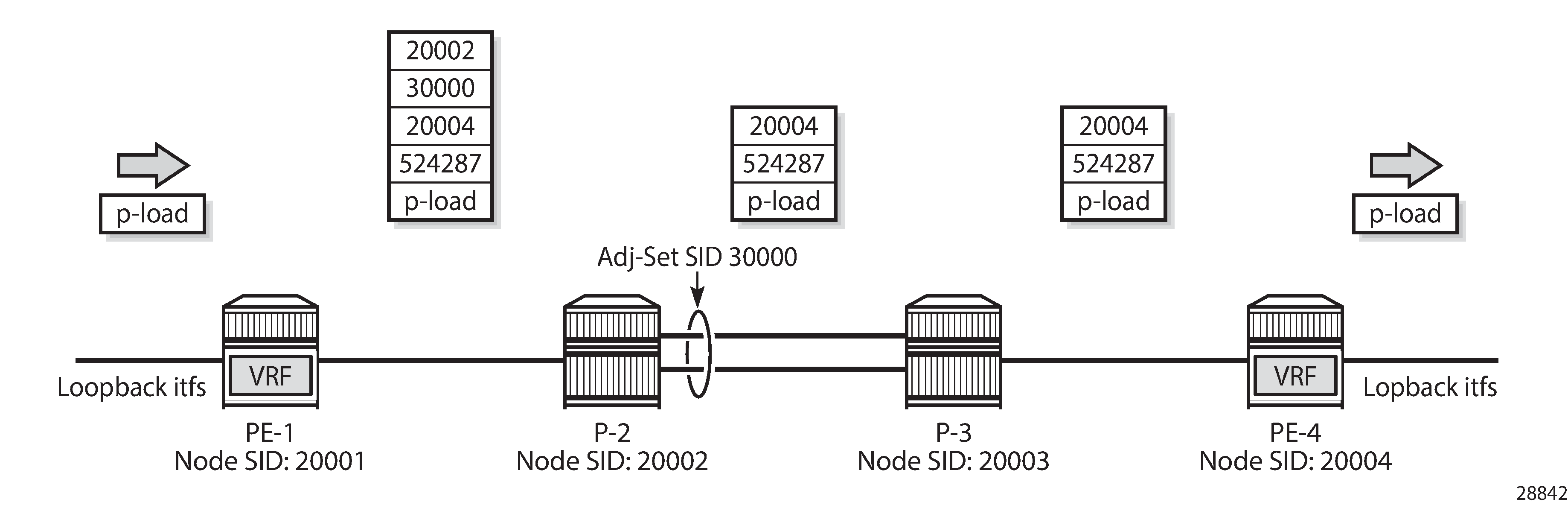
MPLS label stack shows the MPLS label stacks on the path from a loopback interface on PE-1 to a loopback interface on PE-4. PE-1 pushes the {20002, 30000, 20004, 524287} label stack to packets received from a loopback interface on PE-1. The bottom of the stack is the {524287} VPN service label. The active label is node SID 20002, so the traffic flow takes the shortest path to P-2, which pops this label. Because {30000} is the label for the adjacency set, this label is popped while spraying the traffic flow across the two links available to P-3. Now the active label is node SID 20004, so the traffic flow takes the shortest path to PE-4; therefore, P-3 swaps {20004} to {20004}. When the traffic flow arrives at PE-4, PE-4 pops the {20004} node SID and the {524287} VPN service label before delivering the traffic to a loopback interface on PE-4.
The traffic that is sent in this example is a burst of successive pings (8000) in multiple flows (5) from a loopback interface on PE-1 to the different loopback interfaces on PE-4. So, the traffic flows have a variety of source/destination IP-address pairs. Additionally, for the load to be sprayed across the adjacency set members, load balancing must be enabled. On P-2, this is enabled as follows:
# on P-2
configure system load-balancing lsr-load-balancing lbl-ip
P-2 hashes the traffic (ping requests) based on the source and destination IP addresses, thereby spraying the traffic across the int-P-2-P-3-a interface (on port 1/1/1) and the int-P-2-P-3-b interface (on port 1/1/3). P-3 hashes the return traffic (ping responses) similarly across the int-P-3-P-2-a interface (on port 1/1/2) and the int-P-3-P-2-b interface (on port 1/1/3). Because two links are available, both carry a part of the traffic, as follows. Only the monitoring outcome for P-2 is shown; P-3 has a corresponding monitoring outcome.
A:P-2# monitor port 1/1/2 1/1/1 1/1/3 interval 5 repeat 25 absolute

===============================================================================
Monitor statistics for Ports
===============================================================================
                                                   Input                 Output
-------------------------------------------------------------------------------
-------------------------------------------------------------------------------
At time t = 0 sec (Base Statistics)
-------------------------------------------------------------------------------
Port 1/1/2
-------------------------------------------------------------------------------
Octets                                             11416                  12136
Packets                                              124                    124
Errors                                                 0                      0

Port 1/1/1
-------------------------------------------------------------------------------
Octets                                             11969                  11703
Packets                                              125                    124
Errors                                                 0                      0

Port 1/1/3
-------------------------------------------------------------------------------
Octets                                             10102                  10102
Packets                                               99                     99
Errors                                                 0                      0

-------------------------------------------------------------------------------
At time t = 5 sec (Mode: Absolute)
-------------------------------------------------------------------------------
Port 1/1/2
-------------------------------------------------------------------------------
Octets                                             75846                  72206
Packets                                              670                    670
Errors                                                 0                      0

Port 1/1/1
-------------------------------------------------------------------------------
Octets                                             44492                  51523
Packets                                              421                    486
Errors                                                 0                      0

Port 1/1/3
-------------------------------------------------------------------------------
Octets                                             37859                  30626
Packets                                              352                    286
Errors                                                 0                      0

-------------------------------------------------------------------------------

---snip---

-------------------------------------------------------------------------------
At time t = 120 sec (Mode: Absolute)
-------------------------------------------------------------------------------
Port 1/1/2
-------------------------------------------------------------------------------
Octets                                           4734681                4415401
Packets                                            40159                  40159
Errors                                                 0                      0

Port 1/1/1
-------------------------------------------------------------------------------
Octets                                           1775114                2654968
Packets                                            16159                  24159
Errors                                                 0                      0

Port 1/1/3
-------------------------------------------------------------------------------
Octets                                           2652795                1772795
Packets                                            24127                  16127
Errors                                                 0                      0

-------------------------------------------------------------------------------
At time t = 125 sec (Mode: Absolute)
-------------------------------------------------------------------------------
Port 1/1/2
-------------------------------------------------------------------------------
Octets                                           4734964                4415538
Packets                                            40161                  40161
Errors                                                 0                      0

Port 1/1/1
-------------------------------------------------------------------------------
Octets                                           1775371                2655251
Packets                                            16162                  24161
Errors                                                 0                      0

Port 1/1/3
-------------------------------------------------------------------------------
Octets                                           2653262                1773262
Packets                                            24131                  16131
Errors                                                 0                      0

===============================================================================
A:P-2#
The relevant information is available after monitoring all bursts (after 125 seconds): 3 out of 5 flows use the int-P-2-P-3-a interface; 2 out of 5 flows use the int-P-2-P-3-b interface.
With an additional burst to a loopback interface that is reached above over the int-P-2-P-3-a interface, 4 (=3+1) out of now 6 flows use the int-P-2-P-3-a interface; the initial 2 out of 6 flows keep on using the int-P-2-P-3-b interface, as follows:
A:P-2# monitor port 1/1/2 1/1/1 1/1/3 interval 5 repeat 25 absolute

===============================================================================
Monitor statistics for Ports
===============================================================================
                                                   Input                 Output
-------------------------------------------------------------------------------

---snip---

-------------------------------------------------------------------------------
At time t = 125 sec (Mode: Absolute)
-------------------------------------------------------------------------------
Port 1/1/2
-------------------------------------------------------------------------------
Octets                                           5675055                5291655
Packets                                            48120                  48119
Errors                                                 0                      0

Port 1/1/1
-------------------------------------------------------------------------------
Octets                                           2651441                3531342
Packets                                            24120                  32120
Errors                                                 0                      0

Port 1/1/3
-------------------------------------------------------------------------------
Octets                                           2649909                1769836
Packets                                            24097                  16096
Errors                                                 0                      0

===============================================================================
A:P-2#
With a further additional burst to a loopback interface that is reached above over the int-P-2-P-3-b interface, the initial 4 out of now 7 flows keep on using the int-P-2-P-3-a interface; 3 (=2+1) out of 7 flows use the int-P-2-P-3-b interface, as follows:
A:P-2# monitor port 1/1/2 1/1/1 1/1/3 interval 5 repeat 25 absolute

===============================================================================
Monitor statistics for Ports
===============================================================================
                                                   Input                 Output
-------------------------------------------------------------------------------

---snip---

-------------------------------------------------------------------------------
At time t = 125 sec (Mode: Absolute)
-------------------------------------------------------------------------------
Port 1/1/2
-------------------------------------------------------------------------------
Octets                                           6618935                6171269
Packets                                            56117                  56115
Errors                                                 0                      0

Port 1/1/1
-------------------------------------------------------------------------------
Octets                                           2651175                3531102
Packets                                            24117                  32116
Errors                                                 0                      0

Port 1/1/3
-------------------------------------------------------------------------------
Octets                                           3529677                2649844
Packets                                            32094                  24095
Errors                                                 0                      0

===============================================================================
A:P-2#
Conclusion
By defining adjacency sets in SR-enabled networks, operators can apply load sharing to parallel links between adjacent nodes, thereby optimizing the use of network resources.