GRE Tunnel Origination and Termination Using Non-system IP Addresses
This chapter provides information about GRE tunnel origination and termination using non-system IP addresses.
Topics in this chapter include:
Applicability
This chapter was initially written based on SR OS Release 16.0.R5, but the MD-CLI in the current edition corresponds to SR OS Release 23.3.R2. GRE SDPs and auto-bind GRE tunnels can originate and terminate on a non-system IP address in SR OS Release 16.0.R4 or later.
Overview
For scaling purposes, service providers typically deploy seamless MPLS or inter-AS scenarios. In many cases, the system IP address cannot be leaked between domains and a separate loopback address is used to terminate tunnels. GRE termination on a non-system IP address is supported in the following services:
VPLS with manually configured GRE spoke-SDPs
VPLS with BGP-AD using provisioned GRE SDPs (provisioned-sdp use or provisioned-sdp prefer commands)
BGP-VPLS using provisioned GRE SDPs
Epipe with manually configured GRE spoke-SDPs
Epipe with BGP-VPWS using provisioned GRE SDPs
VPRN with manually configured GRE spoke-SDPs
VPRN with auto-bind GRE tunnel
IES with manually configured GRE spoke-SDPs
This chapter focuses on MPLS-over-GRE termination, but IP-over-GRE termination is also supported.
MPLS-over-GRE termination
GRE termination applies to GRE SDPs and auto-bind GRE tunnels concurrently on a system interface and on non-system interfaces with a subnet that is up to and including /16. In the following example, the non-system loopback address 10.0.1.1 with a subnet of /24 is configured as GRE termination on PE-1:
# on PE-1:
configure {
    router "Base" {
        interface "lo1" {
            loopback
            gre-termination true
            ipv4 {
                primary {
                    address 10.0.1.1
                    prefix-length 24
                }
            }
        }
Only one interface can be configured as GRE termination. The following error is raised when attempting to configure a second loopback interface "lo2" as GRE termination on PE-1:
*[ex:/configure router "Base" interface "lo2"]
A:admin@Dut-A# commit
MINOR: COMMON #238: configure router "Base" interface "lo2" - Configuration change failed
validation - Multiple interfaces with gre-termination set in the router
Although the preceding examples are for loopback interfaces, GRE termination can also be configured on other router interfaces, but only one per node. The following shows an attempt to configure interface "int-PE-1-PE-2" on PE-1 as GRE termination. The same error message is raised. However, if it were the first interface on the node to be configured as GRE termination, the configuration would be accepted.
*[ex:/configure router "Base" interface "int-PE-1-PE-2"]
A:admin@Dut-A# commit
MINOR: COMMON #238: configure router "Base" interface "int-PE-1-PE-2" - Configuration change
failed validation - Multiple interfaces with gre-termination set in the router
The maximum size of the GRE termination subnet is /16.
GRE termination cannot be applied on the following interface types:
Unnumbered network IP interfaces
IES interfaces
VPRN interfaces
CSC VPRN interfaces
MPLS-over-GRE origination
GRE SDPs and auto-bind GRE tunnels can originate and terminate on a non-system IP address. Manually configured SDPs can be configured with a non-system IP address as the far-end address. Optionally, a non-system local-end address can be configured for generating GRE from an interface other than the system interface. In the following example on PE-1, GRE SDP 120 uses loopback address 10.0.1.1 as the local-end address and 10.0.2.1 on PE-2 as the far-end address.
# on PE-1:
configure {
    service {
        sdp 120 {
            admin-state enable
            local-end 10.0.1.1
            far-end {
                ip-address 10.0.2.1
            }
        }
The local-end IP address can only be configured for GRE SDPs; the following error message is raised when attempting to configure an MPLS SDP with a local-end address:
*[ex:/configure service sdp 122]
A:admin@PE-1# commit
MINOR: SVCMGR #7720: configure service sdp 122 local-end - Invalid SDP configuration -
local-end is not supported for this sdp delivery-type.
The local-end parameter value complies with the following rules:
A maximum of 15 distinct address values can be configured for all GRE SDPs in the configure service sdp local-end context, and all L2oGRE SDPs under the configure service system gre-eth-bridged tunnel-termination context.
The same source address cannot be used in both contexts because an address configured for an L2oGRE SDP matches an internally created interface that is not available to other applications.
The local-end address of a GRE SDP, when different from the system address, need not match the primary address of an interface that has the MPLS-over-GRE termination subnet configured, unless a GRE SDP or tunnel from the far-end router terminates on this address.
The primary IPv4 address of any local network IP interface, loopback or not, may be used. The following shows that IP address 192.168.12.1, as the IP address of the previously mentioned interface "int-PE-1-PE-2" toward PE-2, can be used as the local-end address:
# on PE-1:
configure {
    service {
        sdp 123 {
            admin-state enable
            local-end 192.168.12.1
            far-end {
                ip-address 10.0.2.1
            }
        }
The following shows that an error message is raised when attempting to configure an invalid local-end IP address, that is, an IP address that is not primary on a local router interface. In this case, local-end IP address 10.99.1.1 does not exist on PE-1.
*[ex:/configure service sdp 120]
A:admin@PE-1# commit
MINOR: MGMT_CORE #4001: configure service sdp 120 - sdp 120: router interface with address
10.99.1.1 does not exist, or is not primary IPv4 address - configure router "Base" description
For services that support auto-binding to a GRE tunnel, the following command configures a single alternate source address (in this case, 10.0.1.1) per system:
# on PE-1:
configure {
    service {
        system {
            vpn-gre-source-ip 10.0.1.1
        }
The default value of the single source address is the primary IPv4 address of the system interface. The value of the vpn-gre-source-ip parameter can be changed at any time. After a new value is configured, the system address will not be used in services that bind to the GRE tunnel.
The vpn-gre-source-ip parameter value complies with the following rules:
This single source address counts toward the maximum of 15 distinct address values per system used by all GRE SDPs under the configure service sdp local-end context and all L2oGRE SDPs under the configure service system gre-eth-bridged tunnel-termination context.
The same source address can be used in both vpn-gre-source-ip and configure service sdp local-end contexts.
The same source address cannot be used in both vpn-gre-source-ip and configure service system gre-eth-bridged tunnel-termination contexts because an address configured for an L2oGRE SDP matches an internally created interface that is not available to other applications.
The vpn-gre-source-ip address, when different from the system IP address, need not match the primary address of an interface that has the MPLS-over-GRE termination subnet configured, unless a GRE SDP or tunnel from the far-end router terminates on this address.
Configuration
Example topology shows the example topology with three SR OS nodes in AS 64500. Services will be configured on PE-1 and PE-2, while RR-3 is a route reflector (RR).
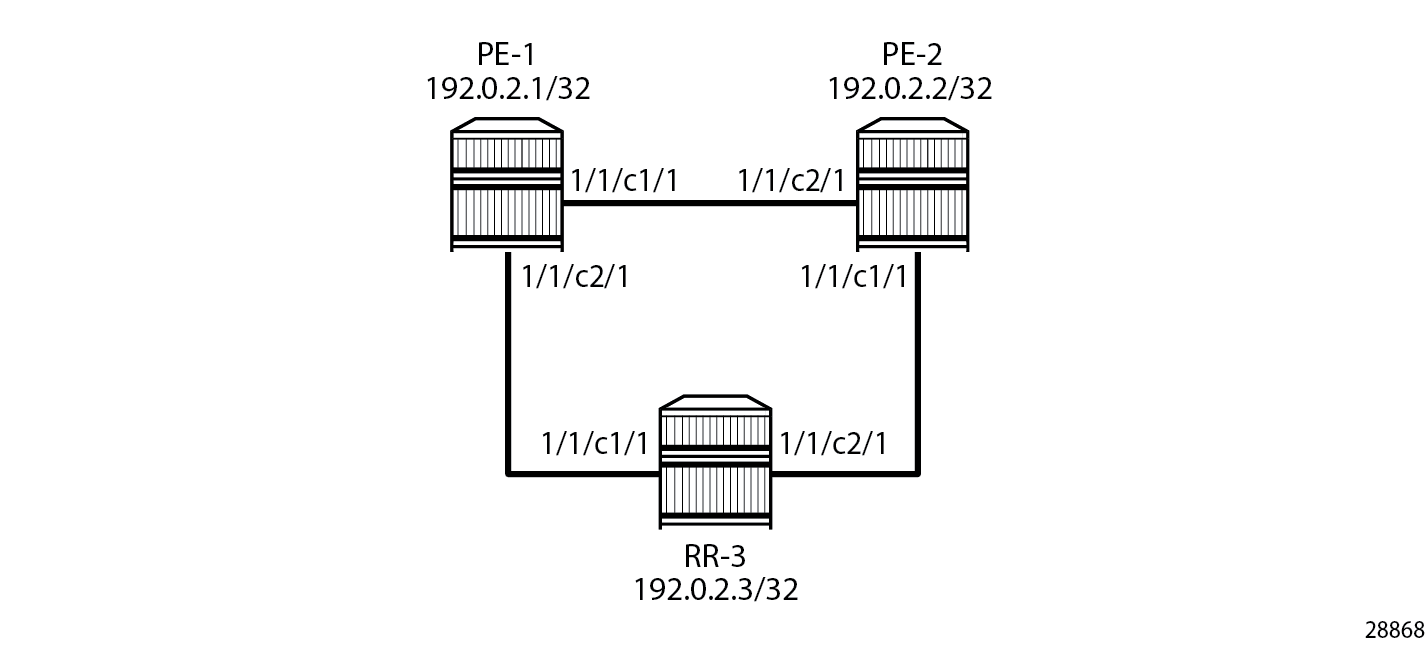
The initial configuration on the three PEs includes:
cards, MDAs, ports
router interfaces. The IP addresses shown on the figure are the system IP addresses 192.0.2.x/32.
IS-IS as IGP (alternatively, OSPF can be used)
GRE SDP termination on non-system IP addresses will be configured in the following use cases:
VPLS with manually configured T-LDP signaled SDP
Epipe with manually configured T-LDP signaled SDP
BGP-VPLS using a provisioned BGP-signaled SDP
BGP-AD in VPLS using a provisioned T-LDP signaled SDP
BGP-VPWS using a provisioned BGP-signaled SDP
VPRN with manually configured T-LDP signaled SDP
VPRN with auto-bind to GRE tunnel
IES with manually configured T-LDP signaled SDP
MPLS-over-GRE termination
On PE-1, PE-2, and RR-3, loopback interface "lo1" is configured as GRE termination with IPv4 address 10.0.x.1/24 for PE-x. The configuration on PE-1 is as follows:
# on PE-1:
configure {
    router "Base" {
        interface "lo1" {
            loopback
            gre-termination true
            ipv4 {
                primary {
                    address 10.0.1.1
                    prefix-length 24
                }
            }
        }
This loopback interface will be used in the SDP configuration. With a /24 subnet, the SDP origination can be any address in the subnet. This is useful for providing entropy in the outer IPv4 header for load-balancing over the IP network.
MPLS-over-GRE origination: SDP local end
The local-end address must be reachable from the far-end router that terminates the GRE SDP. Therefore, the interface for this address can be added to IGP or BGP. Alternatively, a static route can be configured on the far-end router. In this example, IS-IS is enabled on the loopback interface with GRE termination, as follows:
# on PE-1, PE-2, RR-3:
configure {
    router "Base" {
        isis 0 {
            interface "lo1" {
            }
On PE-1, the following SDPs are configured with far-end 10.0.2.1 on PE-2 and local-end 10.0.1.1: SDP 120 with T-LDP signaling (default) and SDP 121 with BGP signaling.
# on PE-1:
configure exclusive
    service {
        sdp 120 {
            admin-state enable
            local-end 10.0.1.1
            far-end {
                ip-address 10.0.2.1
            }
        }
        sdp 121 {
            admin-state enable
            local-end 10.0.1.1
            signaling bgp
            far-end {
                ip-address 10.0.2.1
            }
        }
T-LDP signaled GRE SDPs
When T-LDP signaled SDPs, such as SDP 120 in the preceding example, are configured, T-LDP sessions are auto-created toward the far end of the SDPs. By default, LDP uses the system IP address as source address. However, if the source address for the T-LDP session does not match the destination transport address set by the remote PE, the T-LDP session will not come up and the GRE SDP will remain down.Mismatched T-LDP transport addresses shows an example where SDP auto-created T-LDP sessions use the local system addresses 192.0.2.x and far-end addresses 10.0.0.x, so the GRE SDPs will not come up.
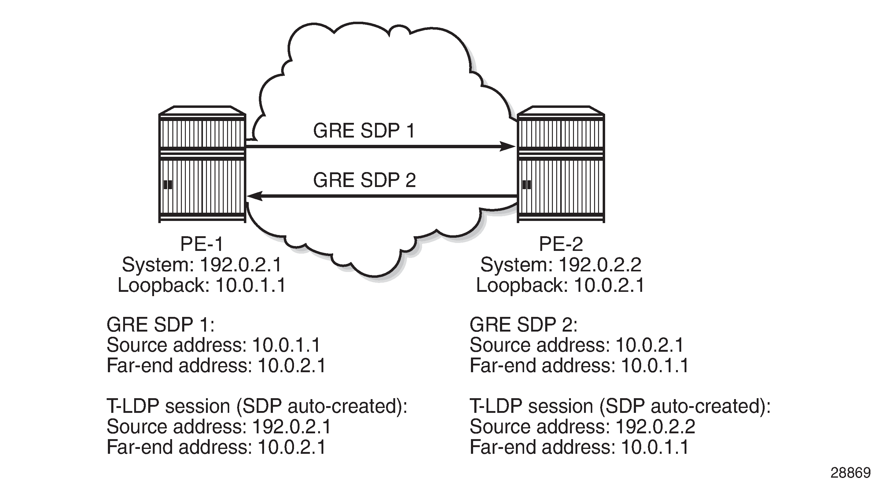
Therefore, the local transport address of the T-LDP session must match the local-end address of the GRE SDP in the PE. These T-LDP sessions can be manually provisioned or auto-created via peer templates. The following configures T-LDP sessions between the non-system IP addresses on PE-1 and PE-2.
# on PE-1:
configure {
    router "Base" {
        ldp {
            targeted-session {
                peer 10.0.2.1 {
                    local-lsr-id {
                        interface-name "lo1"
                    }
                }
            }

# on PE-2:
configure {
    router "Base" {
        ldp {
            targeted-session {
                peer 10.0.1.1 {
                    local-lsr-id {
                        interface-name "lo1"
                    }
                }
            }
Matching T-LDP transport addresses shows the GRE T-LDP signaled SDPs with matching addresses for the T-LDP sessions.

BGP configuration
In this example, the L2 and L3 services are configured on PE-1 and PE-2, while RR-3 acts as the RR. On PE-1, BGP is configured with neighbor 10.0.3.1 and local address 10.0.1.1, as follows. Address family L2-VPN is required for L2 services using BGP-VPLS, BGP-AD, and BGP-VPWS; address family VPN-IPv4 is used for VPRN services.
# on PE-1:
configure {
    router "Base" {
        autonomous-system 64500
        bgp {
            rapid-withdrawal true
            split-horizon true
            group "internal" {
                type internal
                local-address 10.0.1.1
                family {
                    vpn-ipv4 true
                    l2-vpn true
                }
            }
            neighbor "10.0.3.1" {
                group "internal"
            }
        }
The BGP configuration on PE-2 is similar with neighbor 10.0.3.1 and local address 10.0.2.1.
On RR-3, the BGP configuration is as follows.
# on RR-3:
configure {
    router "Base" {
        autonomous-system 64500
        bgp {
            rapid-withdrawal true
            split-horizon true
            group "internal" {
                type internal
                local-address 10.0.3.1
                family {
                    vpn-ipv4 true
                    l2-vpn true
                }
                cluster {
                    cluster-id 10.0.3.1
                }
            }
            neighbor "10.0.1.1" {
                group "internal"
            }
            neighbor "10.0.2.1" {
                group "internal"
            }
        }
The loopback addresses 10.0.x.1 are configured for the local and neighbor addresses.
When the local address 10.0.x.1 is not configured, the system address 192.0.2.x will be used instead. However, in that case, no BGP sessions will be established and, therefore, no BGP routes will be exchanged between 192.0.2.x and 10.0.y.1, and no spoke-SDPs will be auto-created in L2 services using BGP-VPLS, BGP-AD, or BGP-VWPS. Likewise, no BGP-VPN routes will be exchanged between VPRNs on PE-1 and PE-2.
L2 services
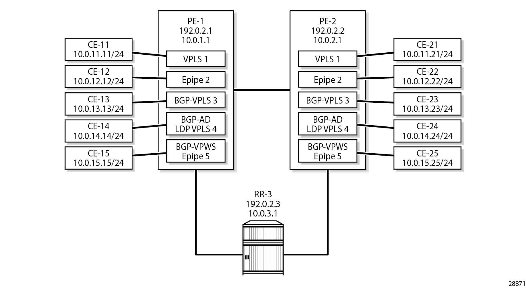
L2 services on PE-1 and PE-2 shows the example topology with the following L2 services configured on PE-1 and PE-2:
VPLS 1 with manually configured spoke-SDP 120:1
Epipe 2 with manually configured spoke-SDP 120:2
BGP-VPLS 3 using PW template 1 (BGP-signaled SDP 121 is used)
LDP VPLS 4 with BGP-AD using PW template 1 (T-LDP signaled SDP 120 is used)
BGP-VPWS Epipe 5 using PW template 1 (BGP-signaled SDP 121 is used)
The CEs are VPRNs configured on the PEs and connected to the VPLSs via port cross-connect (PXC).
For a description of the BGP-VPLS parameters, see the BGP VPLS chapter; for BGP-AD, see the LDP VPLS Using BGP Auto-Discovery chapter; for BGP-VPWS, see the BGP Virtual Private Wire Services chapter. For BGP-VPLS, BGP-AD, and BGP-VPWS, PW template 1 is configured with the provisioned-sdp use command. The service configuration on PE-1 is as follows; the service configuration on PE-2 is similar.
# on PE-1:
configure {
    service {
        sdp 120 {
            admin-state enable
            local-end 10.0.1.1
            far-end {
                ip-address 10.0.2.1
            }
        }
        sdp 121 {
            admin-state enable
            local-end 10.0.1.1
            signaling bgp
            far-end {
                ip-address 10.0.2.1
            }
        }
        pw-template "PW1-use-prov-SDP" {
            pw-template-id 1
            provisioned-sdp use
        }
        vpls "VPLS-1" {
            admin-state enable
            description "VPLS 1 with manually configured spoke-SDP"
            service-id 1
            customer "1"
            spoke-sdp 120:1 {
            }
            sap pxc-10.a:1 {
            }
        }
        epipe "Epipe-2" {
            admin-state enable
            description "Epipe 2 with manually configured spoke-SDP"
            service-id 2
            customer "1"
            spoke-sdp 120:2 {
            }
            sap pxc-10.a:2 {
            }
        }
        vpls "BGP-VPLS-3" {
            admin-state enable
            description "BGP-VPLS with use provisioned SDP"
            service-id 3
            customer "1"
            bgp 1 {
                route-distinguisher "64500:3"
                route-target {
                    export "target:64500:3"
                    import "target:64500:3"
                }
                pw-template-binding "PW1-use-prov-SDP" {
                }
            }
            bgp-vpls {
                admin-state enable
                maximum-ve-id 100
                ve {
                    name "PE-1"
                    id 1
                }
            }
            sap pxc-10.a:3 {
            }
        }
        vpls "BGP-AD VPLS-4" {
            admin-state enable
            description "BGP-AD for LDP VPLS with use provisioned SDP"
            service-id 4
            customer "1"
            bgp 1 {
                route-distinguisher "64500:4"
                route-target {
                    export "target:64500:4"
                    import "target:64500:4"
                }
                pw-template-binding "PW1-use-prov-SDP" {
                }
            }
            bgp-ad {
                admin-state enable
                vpls-id "64500:4"
            }
            sap pxc-10.a:4 {
            }
        }
        epipe "BGP-VPWS-5" {
            admin-state enable
            description "BGP-VPWS with use provisioned SDP"
            service-id 5
            customer "1"
            bgp 1 {
                route-distinguisher "64500:5"
                route-target {
                    export "target:64500:5"
                    import "target:64500:5"
                }
                pw-template-binding "PW1-use-prov-SDP" {
                }
            }
            bgp-vpws {
                admin-state enable
                local-ve {
                    name "PE-1"
                    id 1
                }
                remote-ve "PE-2" {
                    id 2
                }
            }
            sap pxc-10.a:5 {
            }
        }
The following BGP sessions are established between PE-1 and RR-3 for the VPN-IPv4 and L2VPN address families:
[/]
A:admin@PE-1# show router bgp summary all

===============================================================================
BGP Summary
===============================================================================
Legend : D - Dynamic Neighbor
===============================================================================
Neighbor
Description
ServiceId          AS PktRcvd InQ  Up/Down   State|Rcv/Act/Sent (Addr Family)
                      PktSent OutQ
-------------------------------------------------------------------------------
10.0.3.1
Def. Inst       64500      20    0 00h06m41s 0/0/0 (VpnIPv4)
                           23    0           3/3/3 (L2VPN)

-------------------------------------------------------------------------------
On PE-1, the following T-LDP session is established to 10.0.2.1 on PE-2:
[/]
A:admin@PE-1# show router ldp session ipv4

==============================================================================
LDP IPv4 Sessions
==============================================================================
Peer LDP Id         Adj Type  State         Msg Sent  Msg Recv  Up Time
------------------------------------------------------------------------------
10.0.2.1:0          Targeted  Established   115       117       0d 00:09:26
------------------------------------------------------------------------------
No. of IPv4 Sessions: 1
==============================================================================
On PE-1, the following SDPs are created with far end 10.0.2.1 and GRE delivery. For SDP 120, T-LDP signaling is used; BGP signaling is used for SDP 121.
[/]
A:admin@PE-1# show service sdp

============================================================================
Services: Service Destination Points
============================================================================
SdpId  AdmMTU  OprMTU  Far End          Adm  Opr         Del     LSP   Sig
----------------------------------------------------------------------------
120    0       8954    10.0.2.1         Up   Up          GRE     n/a   TLDP
121    0       8954    10.0.2.1         Up   Up          GRE     n/a   BGP
----------------------------------------------------------------------------
Number of SDPs : 2
----------------------------------------------------------------------------
Legend: R = RSVP, L = LDP, B = BGP, M = MPLS-TP, n/a = Not Applicable
        I = SR-ISIS, O = SR-OSPF, T = SR-TE, F = FPE
============================================================================
On PE-1, the following SDP-bindings are used:
[/]
A:admin@PE-1# show service sdp-using

===============================================================================
SDP Using
===============================================================================
SvcId      SdpId              Type   Far End              Opr   I.Label E.Label
                                                          State
-------------------------------------------------------------------------------
1          120:1              Spok   10.0.2.1             Up    524278  524278
2          120:2              Spok   10.0.2.1             Up    524276  524276
3          121:4294967294     BgpVp* 10.0.2.1             Up    524280  524279
4          120:4294967295     BgpAd  10.0.2.1             Up    524275  524275
5          121:4294967293     BgpVp* 10.0.2.1             Up    524277  524277
-------------------------------------------------------------------------------
Number of SDPs : 5
-------------------------------------------------------------------------------
===============================================================================
* indicates that the corresponding row element may have been truncated.
When the loopback interface "lo1" is configured as GRE termination on PE-1 and PE-2, the CEs can send traffic to each other. The following ping messages verify the connectivity between CE-11 and CE-21, CE-12 and CE-22, and so on:
[/]
A:admin@PE-1# ping 10.0.11.21 router-instance "CE-11" interval 0.1 output-format summary
PING 10.0.11.21 56 data bytes
!!!!!
---- 10.0.11.21 PING Statistics ----
5 packets transmitted, 5 packets received, 0.00% packet loss
round-trip min = 3.49ms, avg = 3.70ms, max = 4.11ms, stddev = 0.216ms

[/]
A:admin@PE-1# ping 10.0.12.22 router-instance "CE-12" interval 0.1 output-format summary
PING 10.0.12.22 56 data bytes
!!!!!
---- 10.0.12.22 PING Statistics ----
5 packets transmitted, 5 packets received, 0.00% packet loss
round-trip min = 3.54ms, avg = 4.58ms, max = 8.21ms, stddev = 1.82ms

[/]
A:admin@PE-1# ping 10.0.13.23 router-instance "CE-13" interval 0.1 output-format summary
PING 10.0.13.23 56 data bytes
!!!!!
---- 10.0.13.23 PING Statistics ----
5 packets transmitted, 5 packets received, 0.00% packet loss
round-trip min = 3.65ms, avg = 4.73ms, max = 8.67ms, stddev = 1.97ms

[/]
A:admin@PE-1# ping 10.0.14.24 router-instance "CE-14" interval 0.1 output-format summary
PING 10.0.14.24 56 data bytes
!!!!!
---- 10.0.14.24 PING Statistics ----
5 packets transmitted, 5 packets received, 0.00% packet loss
round-trip min = 3.76ms, avg = 6.67ms, max = 13.3ms, stddev = 3.82ms

[/]
A:admin@PE-1# ping 10.0.15.25 router-instance "CE-15" interval 0.1 output-format summary
PING 10.0.15.25 56 data bytes
!!!!!
---- 10.0.15.25 PING Statistics ----
5 packets transmitted, 5 packets received, 0.00% packet loss
round-trip min = 3.66ms, avg = 4.64ms, max = 7.89ms, stddev = 1.63ms
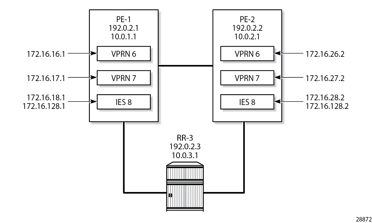
L3 services
L3 services on PE-1 and PE-2 shows the example topology with the following three L3 services configured on PE-1 and PE-2:
VPRN 6 with manually configured spoke-SDP 120:6
VPRN 7 with auto-bind to GRE tunnel
IES 8 with manually configured spoke-SDP 120:8
VPRN 6 is configured with a loopback interface and a GRE spoke-SDP, as follows:
# on PE-1:
configure {
    service {
        system {
            bgp-auto-rd-range {
                ip-address 10.0.1.1
                community-value {
                    start 60000
                    end 65000
                }
            }
        }
        vprn "VPRN-6 with GRE spoke-SDP" {
            admin-state enable
            service-id 6
            customer "1"
            bgp-ipvpn {
                mpls {
                    admin-state enable
                    route-distinguisher auto-rd
                    vrf-target {
                        community "target:64500:6"
                    }
                }
            }
            interface "lo6" {
                loopback true
                ipv4 {
                    primary {
                        address 172.16.16.1
                        prefix-length 32
                    }
                }
            }
            spoke-sdp 120:6 {
            }
        }
The following forwarding information base (FIB) for VPRN 6 shows that the remote prefix is reachable via a transport tunnel using SDP 120:
[/]
A:admin@PE-1# show router 6 fib 1

===============================================================================
FIB Display
===============================================================================
Prefix [Flags]                                              Protocol
  NextHop
-------------------------------------------------------------------------------
172.16.16.1/32                                              LOCAL
  172.16.16.1 (lo6)
172.16.26.2/32                                              BGP_VPN
  10.0.2.1 (VPRN Label:524273 Transport:SDP:120)
-------------------------------------------------------------------------------
Total Entries : 2
-------------------------------------------------------------------------------
===============================================================================
VPRN 7 is configured with auto-bind-tunnel and the tunnel needs to be resolved using GRE. For services that support auto-binding to a GRE tunnel, the vpn-gre-source-ip parameter defines a single alternate source address for all VPRNs on the system. On PE-1, the configuration is as follows:
# on PE-1:
configure {
    service {
        system {
            vpn-gre-source-ip 10.0.1.1
        }
        vprn "VPRN-7 with auto-bind GRE" {
            admin-state enable
            service-id 7
            customer "1"
            bgp-ipvpn {
                mpls {
                    admin-state enable
                    route-distinguisher auto-rd
                    vrf-target {
                        community "target:64500:7"
                    }
                    auto-bind-tunnel {
                        resolution filter
                        resolution-filter {
                            gre true
                        }
                    }
                }
            }
            interface "lo7" {
                loopback true
                ipv4 {
                    primary {
                        address 172.16.17.1
                        prefix-length 24
                    }
                }
            }
        }
The following FIB for VPRN 7 shows that the remote prefix is reachable via a GRE transport tunnel:
[/]
A:admin@PE-1# show router 7 fib 1

===============================================================================
FIB Display
===============================================================================
Prefix [Flags]                                              Protocol
  NextHop
-------------------------------------------------------------------------------
172.16.17.0/24                                              LOCAL
  172.16.17.0 (lo7)
172.16.27.0/24                                              BGP_VPN
  10.0.2.1 (VPRN Label:524271 Transport:GRE)
-------------------------------------------------------------------------------
Total Entries : 2
-------------------------------------------------------------------------------
===============================================================================
IES 8 has an interface with a manually configured GRE spoke-SDP, as follows:
# on PE-1:
configure {
    service {
        ies "IES-8" {
            admin-state enable
            service-id 8
            customer "1"
            interface "int-IES8-PE-1-PE-2" {
                spoke-sdp 120:8 {
                }
                ipv4 {
                    primary {
                        address 172.16.128.1
                        prefix-length 30
                    }
                }
            }
            interface "lo8" {
                loopback true
                ipv4 {
                    primary {
                        address 172.16.18.1
                        prefix-length 24
                    }
                }
            }
        }
On PE-1, the connectivity over the GRE spoke-SDP is verified as follows:
[/]
A:admin@PE-1# ping 172.16.128.2 interval 0.1 output-format summary
PING 172.16.128.2 56 data bytes
!!!!!
---- 172.16.128.2 PING Statistics ----
5 packets transmitted, 5 packets received, 0.00% packet loss
round-trip min = 2.57ms, avg = 2.73ms, max = 3.01ms, stddev = 0.168ms
Conclusion
By default, GRE SDPs and auto-bind GRE tunnels are originated and terminated on the system IP address, but it is possible to use non-system IP addresses. This is useful in cases where the system IP address cannot be leaked between domains and a separate loopback address must be used to terminate tunnels.