BGP VPLS
This chapter describes advanced BGP VPLS configurations.
Topics in this chapter include:
Applicability
This chapter was initially written for SR OS Release 9.0.R3. The MD-CLI in the current edition corresponds to SR OS Release 20.10.R2. There are no prerequisites for this configuration.
Overview
The following two IETF standards describe the provisioning of Virtual Private LAN Services (VPLS).
-
RFC 4762, Virtual Private LAN Service (VPLS) Using Label Distribution Protocol (LDP) Signaling, describes Label Distribution Protocol (LDP) VPLS, where VPLS pseudowires are signaled using LDP between VPLS Provider Edge (PE) routers, either configured manually or auto-discovered using BGP.
-
RFC 4761, Virtual Private LAN Service (VPLS) Using BGP for Auto-Discovery and Signaling, describes the use of Border Gateway Protocol (BGP) for both the auto-discovery of VPLS PEs and signaling of pseudowires between such PEs.
The purpose of this chapter is to describe the configuration and troubleshooting for BGP-VPLS.
Knowledge of BGP-VPLS RFC 4761 architecture and functionality is assumed throughout this chapter, as well as knowledge of Multi-Protocol BGP (MP-BGP).
Example topology shows the example topology with seven SR OS nodes located in the same Autonomous System (AS).
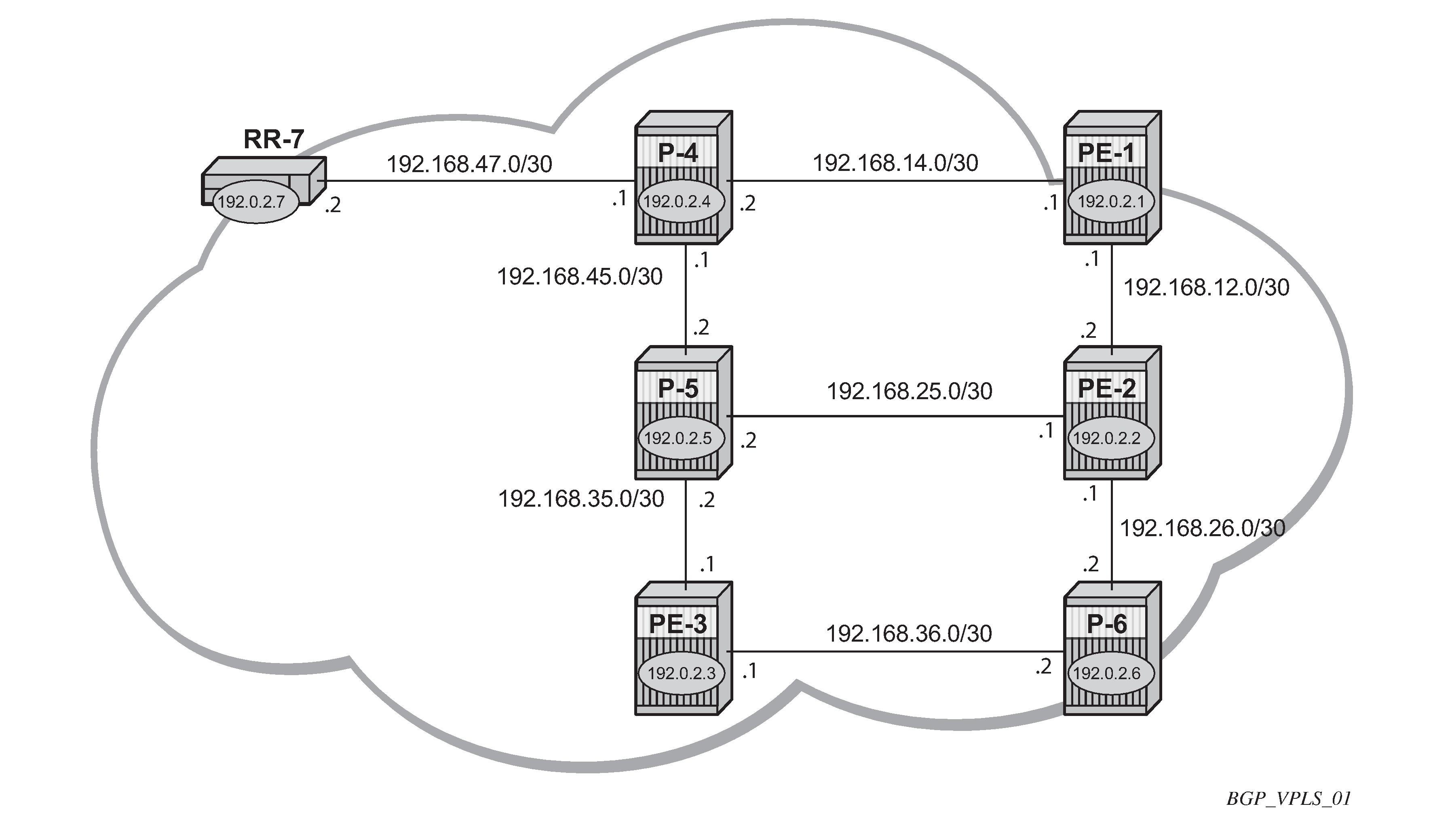
There are three Provider Edge (PE) routers, and RR-7 acts as a Route Reflector (RR) for the AS. The PE routers are all VPLS-aware, the Provider (P) routers are VPLS-unaware and do not take part in the BGP process.
The following configuration tasks are completed as a prerequisite:
-
IS-IS or OSPF on each of the network interfaces between the PE/P routers and RR.
-
MPLS is configured on all interfaces between PE routers and P routers. MPLS is not required between P-4 and RR-7.
-
LDP is configured on interfaces between PE and P routers. It is not required between P-4 and the RR-7.
-
The RSVP protocol is enabled.
BGP VPLS
In this architecture, a VPLS instance is a collection of local VPLS instances present on a number of PEs in a provider network. In this context, any VPLS-aware PE is also known as a VPLS Edge (VE) device.
The PEs communicate with each other at the control plane level by means of BGP updates containing BGP-VPLS Network Layer Reachability Information (NLRI). Each update contains enough information for a PE to determine the presence of other local VPLS instances on peering PEs and to set up pseudowire connectivity for data flow between peers containing a local VPLS within the same VPLS instance. Therefore, auto-discovery and pseudowire signaling are achieved using a single BGP update message.
Each PE within a VPLS instance is identified by a VPLS Edge identifier (VE-ID) and the presence of a VPLS instance is determined using the exchange of standard BGP extended community RTs between PEs.
Each PE will advertise, via the route reflectors, the presence of each VPLS instance to all other PEs, along with a block of multiplexer labels that can be used to communicate between such instances plus a BGP next hop that determines a labeled transport tunnel between PEs.
Each VPLS instance is configured with import and export RT extended communities for topology control, along with VE identification.
Configuration
The first step is to configure an MP-iBGP session between each of the PEs and the RR for the L2-VPN address family, as follows:
# on PE-1, PE-2, and PE-3:
configure {
    router "Base" {
        autonomous-system 65536
        bgp {
            group "INTERNAL" {
                peer-as 65536
                family {
                    l2-vpn true
                }
            }
            neighbor "192.0.2.7" {
                group "INTERNAL"
            }
The IP addresses can be derived from Example topology.
The BGP configuration for RR-7 is as follows:
# on RR-7:
configure {
    router "Base" {
        autonomous-system 65536
        bgp {
            cluster {
                cluster-id 1.1.1.1
            }
            group "RR-INTERNAL" {
                peer-as 65536
                family {
                    l2-vpn true
                }
            }
            neighbor "192.0.2.1" {
                group "RR-INTERNAL"
            }
            neighbor "192.0.2.2" {
                group "RR-INTERNAL"
            }
            neighbor "192.0.2.3" {
                group "RR-INTERNAL"
            }
On PE-1, the BGP session with RR-7 is established with the L2-VPN address family capability negotiated, as follows:
[]
A:admin@PE-1# show router bgp neighbor 192.0.2.7

===============================================================================
BGP Neighbor
===============================================================================
-------------------------------------------------------------------------------
Peer                 : 192.0.2.7
Description          : (Not Specified)
Group                : INTERNAL
-------------------------------------------------------------------------------
Peer AS              : 65536            Peer Port            : 50198
Peer Address         : 192.0.2.7
Local AS             : 65536            Local Port           : 179
Local Address        : 192.0.2.1
Peer Type            : Internal         Dynamic Peer         : No
State                : Established      Last State           : Established
Last Event           : recvOpen
Last Error           : Cease (Connection Collision Resolution)
Local Family         : L2-VPN
Remote Family        : L2-VPN
Hold Time            : 90               Keep Alive           : 30
Min Hold Time        : 0
Active Hold Time     : 90               Active Keep Alive    : 30
Cluster Id           : None
Preference           : 170              Num of Update Flaps  : 0
---snip---

Local Capability     : RtRefresh MPBGP 4byte ASN
Remote Capability    : RtRefresh MPBGP 4byte ASN
---snip---
On RR-7, the BGP sessions with each PE are established, and have negotiated the L2-VPN address family capability, as follows:
[]
A:admin@RR-7# show router bgp summary all

===============================================================================
BGP Summary
===============================================================================
Legend : D - Dynamic Neighbor
===============================================================================
Neighbor
Description
ServiceId          AS PktRcvd InQ  Up/Down   State|Rcv/Act/Sent (Addr Family)
                      PktSent OutQ
-------------------------------------------------------------------------------
192.0.2.1
Def. Instance  65536       11    0 00h04m29s 0/0/0 (L2VPN)
                           11    0
192.0.2.2
Def. Instance  65536       11    0 00h04m29s 0/0/0 (L2VPN)
                           11    0
192.0.2.3
Def. Instance  65536       11    0 00h04m29s 0/0/0 (L2VPN)
                           11    0

-------------------------------------------------------------------------------
A full mesh of RSVP-TE LSPs is configured between the PE routers. On PE-1, the MPLS interface and LSP configuration are as follows:
# on PE-1:
configure {
    router "Base" {
        mpls {
            admin-state enable
            interface "int-PE-1-P-4" {
            }
            interface "int-PE-1-PE-2" {
            }
            path "loose" {
                admin-state enable
            }
            lsp "LSP-PE-1-PE-2" {
                admin-state enable
                type p2p-rsvp
                to 192.0.2.2
                primary "loose" {
                }
            }
            lsp "LSP-PE-1-PE-3" {
                admin-state enable
                type p2p-rsvp
                to 192.0.2.3
                primary "loose" {
                }
            }
The MPLS and LSP configuration for PE-2 and PE-3 are similar to that of PE-1 with the appropriate interfaces and LSP names configured.
BGP VPLS PE configuration
Pseudowire templates
Pseudowire templates are used by BGP to dynamically instantiate SDP bindings for a service to signal the egress service de-multiplexer labels used by remote PEs to reach the local PE.
The template determines the signaling parameters of the pseudowire, control word presence, MAC-pinning, filters, and so on, plus other usage characteristics such as split horizon groups (SHGs).
The MPLS transport tunnel between PEs can be signaled using LDP or RSVP-TE.
LDP based pseudowires can be automatically instantiated. RSVP-TE based SDPs have to be pre-provisioned.
Pseudowire templates for auto-SDP creation using LDP
In order to use an LDP transport tunnel for data flow between PEs, link layer LDP must be configured between all PEs/Ps, so that a transport label for each PE’s system interface is available.
# on PE-1:
configure (
    router "Base" {
        ldp {
            interface-parameters {
                interface "int-PE-1-P-4" {
                    ipv4 {
                    }
                }
                interface "int-PE-1-PE-2" {
                    ipv4 {
                    }
                }
            }
        }
Using this mechanism, SDPs can be auto-instantiated with SDP-IDs starting at the higher end of the SDP numbering range, such as 32767. Any subsequent SDPs created use SDP-IDs decrementing from this value.
A pseudowire template is required containing an SHG. Each SDP created with this template is contained within an SHG so that traffic cannot be forwarded between them.
# on PE-1:
configure {
    service {
        pw-template "PW1" {
            pw-template-id 1
            split-horizon-group {
                name "VPLS-SHG"
            }
        }
The pseudowire template also has the following options available when used for BGP-VPLS:
[ex:configure service]
A:admin@PE-1# pw-template "PW1" ?

 ---snip---

 control-word          - Enable/Disable the use of ControlWord
 ---snip---

 force-vc-forwarding   - VC forwarding action
 ---snip---

 vc-type               - Type of virtual circuit associated with the SDP bind.
 ---snip---
-
The control word will determine whether the C flag is set in the Layer 2 extended community and, therefore, if a control word is used in the pseudowire.
-
The force-vlan-vc-forwarding command will add a tag (equivalent to vc-type vlan) and will allow for customer QoS transparency (dot1p + Drop Eligibility (DE) bits).
[ex:configure service pw-template "PW1"] A:admin@PE-1# force-vc-forwarding ? force-vc-forwarding <keyword> <keyword> - (vlan|qinq-c-tag-c-tag|qinq-s-tag-c-tag) -
The encap type in the Layer 2 extended community is always 19 (VPLS encap), therefore, the vc-type will always be ether regardless of the configured value on the vc-type.
[ex:configure service pw-template "PW1"]
A:admin@PE-1# vc-type ?

 vc-type <keyword>
 <keyword>  - (ether|vlan)
 Default    - ether

    Type of virtual circuit associated with the SDP bind.
Pseudowire templates for provisioned SDPs using RSVP-TE
To use an RSVP-TE tunnel as transport between PEs, it is necessary to bind the RSVP-TE LSP between PEs to an SDP.
The following SDP is created from PE-1 to PE-2:
# on PE-1:
configure {
    service {
        sdp 12 {
            admin-state enable
            description "SDP-PE-1-PE-2_RSVP_BGP"
            delivery-type mpls
            signaling bgp
            far-end {
                ip-address 192.0.2.2
            }
            lsp "LSP-PE-1-PE-2" { }
        }
The signaling bgp parameter is required for BGP-VPLS to be able to use this SDP. Conversely, SDPs that are bound to RSVP-based LSPs with signaling set to the default value of tldp will not be used as SDPs within BGP-VPLS.
BGP VPLS using auto-provisioned SDPs
BGP VPLS using auto-provisioned SDPs shows a VPLS instance where SDPs are auto-provisioned. In this case, the transport tunnels are LDP-signaled.
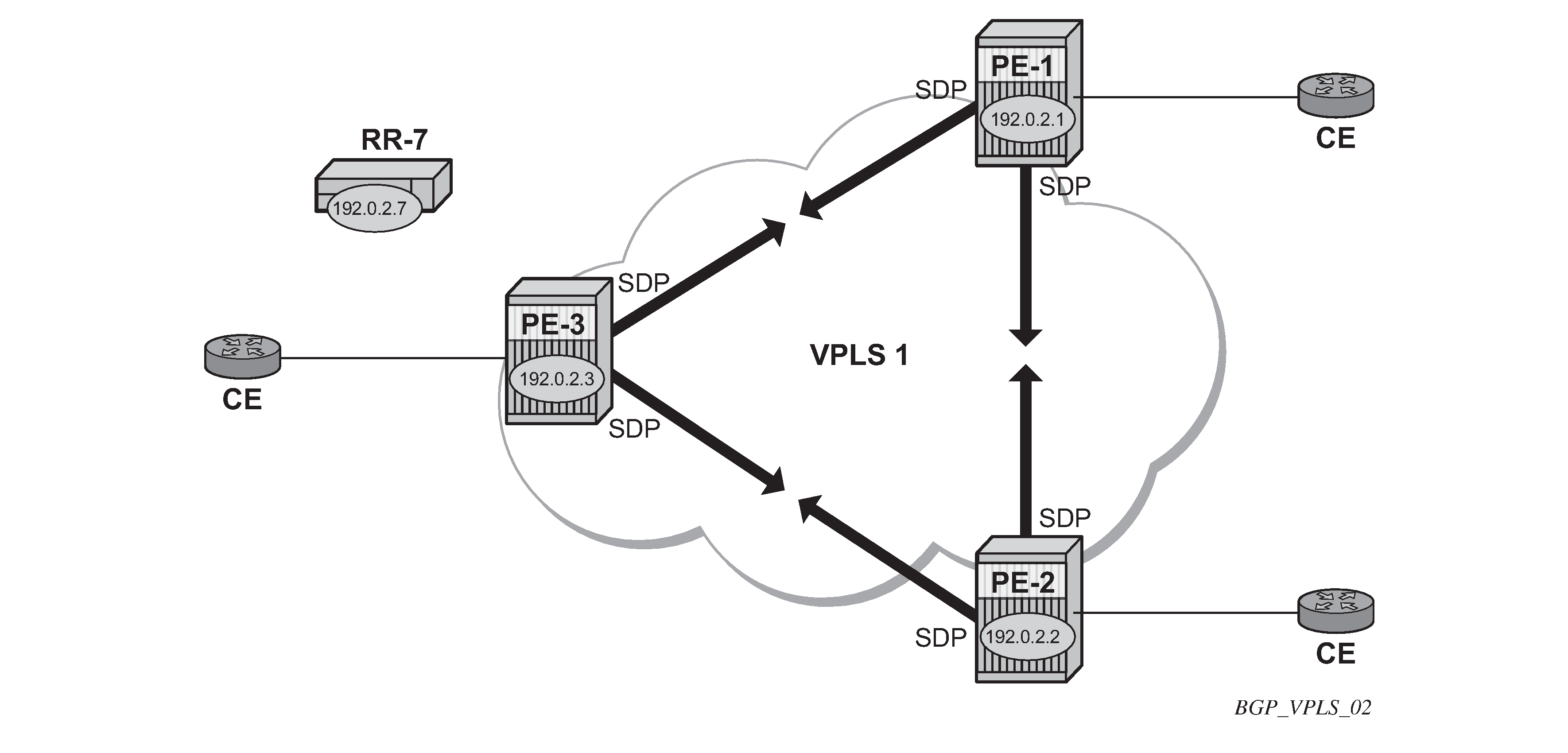
The following shows the configuration required on PE-1 for a BGP-VPLS service using a pseudowire template configured for auto-provisioning of SDPs.
# on PE-1:
configure {
    service {
        pw-template "PW1" {
            pw-template-id 1
            split-horizon-group {
                name "VPLS-SHG"
            }
        }
        vpls "VPLS1_PE-1" {
            admin-state enable
            service-id 1
            customer "1"
            bgp 1 {
                route-distinguisher "65536:1"
                route-target {
                    export "target:65536:1"
                    import "target:65536:1"
                }
                pw-template-binding "PW1" {
                }
            }
            bgp-vpls {
                admin-state enable
                maximum-ve-id 10
                ve {
                    name "PE-1"
                    id 1
                }
            }
            sap 1/1/4:1.0 {
            }
        }
The bgp context specifies parameters which are valid for all of the VPLS BGP applications, such as BGP multi-homing (BGP-MH), BGP auto-discovery (BGP-AD), and BGP-VPLS.
Within the bgp context, parameters are configured that are used by neighboring PEs to determine membership of a VPLS instance, such as the auto-discovery of PEs containing the same VPLS instance; the route distinguisher (RD) is configured, along with the route target (RT) extended communities.
RT communities are used to determine membership of a VPLS instance. The import RT at the BGP level is mandatory. The pseudowire template bind is then applied by the service manager on the received routes matching the RT value.
Within the bgp-vpls context, the signaling parameters are configured. These determine the service labels required for the data plane of the VPLS instance.
The VPLS edge ID (VE-ID) is a numerical value assigned to each PE within a VPLS instance. This value should be unique for a VPLS instance; no two PEs within the same instance should have the same VE-ID values.
A more specific RT can be applied to a pseudowire template in order to define a specific pseudowire topology, rather than only a full mesh, using the command within the bgp context:
[ex:configure service vpls "VPLS1_PE-1" bgp 1 pw-template-binding "PW1"]
A:admin@PE-1# import-rt ?

 import-rt <value>
 import-rt [<value>...] - 0..5 system-ordered values separated by spaces enclosed by
                          brackets

 <value> - <string>
 <string> - <10..28 characters>

    Import route-target communities
Changes to the import policies are not taken once the pseudowire has been set up (changes on RT are refreshed though). Pseudowire templates can be re-evaluated with the command tools perform service eval-pw-template. The eval-pw-template command checks whether all the bindings using this pseudowire template policy are still meant to use this policy.
If the policy has changed and allow-service-impact is true, then the old binding is removed and it is re-added with the new template.
VE-ID and BGP label allocations
The choice of VE-ID is crucial in ensuring efficient allocation of de-multiplexer labels. The most efficient choice is for VE-IDs to be allocated starting at 1 and incrementing for each PE as the following section explains.
The maximum-ve-id value determines the range of the VE-ID value that can be configured. If a PE receives a BGP-VPLS update containing a VE-ID with a greater value than the configured maximum-ve-id, then the update is dropped and no service labels are installed for this VE-ID.
The maximum-ve-id command also checks the locally-configured VE-ID, and prevents a higher value from being used.
Each PE allocates blocks of labels per VPLS instance to remote PEs, in increments of eight labels. It achieves this by advertising three parameters in a BGP update message,
-
A label base (LB) which is the lowest label in the block
-
A VE Block Size (VBS) which is always eight labels, and cannot be changed
-
A VE Base Offset (VBO).
This defines a block of labels in the range (LB, LB+1, ..., LB+VBS-1).
As an example, if the label base (LB) = 524272, then the range for the block is 524272 to 524279, which is exactly eight labels, as per the block size. (The last label in the block is calculated as 524272+8-1 = 524279)
The label allocated by the PE to each remote PE within the VPLS is chosen from this block and is determined by its VE-ID. In this way, each remote PE has a unique de-multiplexer label for that VPLS.
To reduce label wastage, contiguous VE-IDs in the range (N..N+7) per VPLS should be chosen, where N>0.
Assuming a collection of PEs with contiguous VE-IDs, the following labels will be chosen by PEs from the label block allocated by PE-1 which has a VE-ID =1.
|
VE-ID |
Label |
|---|---|
|
2 |
524273 |
|
3 |
524274 |
|
4 |
524275 |
|
5 |
524276 |
|
6 |
524277 |
|
7 |
524278 |
|
8 |
524279 |
This shows that the label allocated to a PE is (LB+VEID-1). The "1" is the VE block offset (VBO).
This means that the label allocated to a PE router within the VPLS can now be written as (LB + VEID - VBO), which means that (VEID - VBO) calculation must always be at least zero and be less than the block size, which is always 8.
For VE-ID < 8, a label will be allocated from this block.
For the next block of 8 VE-IDs (VE-ID 9 to VE-ID 16) a new block of 8 labels must be allocated, so a new BGP update is sent, with a new label base, and a block offset of 9.
VE-IDs and Number of Labels shows how the choice of VE-IDs can affect the number of label blocks allocated, and therefore the number of labels:
|
VE-ID |
Block Offset |
Labels Allocated |
|---|---|---|
|
1-8 |
1 |
8 |
|
9-16 |
9 |
8 |
|
17-24 |
17 |
8 |
|
25-32 |
25 |
8 |
|
33-40 |
33 |
8 |
|
41-48 |
41 |
8 |
|
49-56 |
49 |
8 |
This shows that the most efficient use of labels occurs when the VE-IDs for a set of PEs are chosen from the same block offset.
If VE-IDs are chosen that map to different block offsets, then each PE will have to send multiple BGP updates to signal service labels. Each PE sends label blocks in BGP updates to each of its BGP neighbors for all label blocks in which at least one VE-ID has been seen by this PE (it does not advertise label blocks which do not contain an active VE-ID, where active VE-ID means the VE-ID of this PE or any other PE in this VPLS).
The maximum-ve-id must be configured first, and determines the maximum value of the VE-ID that can be configured within the PE. The VE-ID value cannot be higher than this within the PE configuration, VE-ID <= maximum VE-ID. Similarly, if the VE-ID within a received NLRI is higher than the maximum VE-ID value, it will not be accepted as valid consequently the maximum VE-ID configured on all PEs must be greater than or equal to any VE-ID used in the VPLS.
Only one VE-ID value can be configured. If the VE-ID value is changed, BGP withdraws the NLRI and sends a route-refresh.
If the same VE-ID is used in different PEs for the same VPLS, a Designated Forwarder (DF) election takes place.
Executing the admin-state disable command triggers an MP-UNREACH-NLRI from the PE to all BGP peers.
The admin-state enable command triggers an MP-REACH-NLRI to the same peers.
PE-2 service creation
On PE-2, a VPLS service using pseudowire template 1 is created. In order to make the label allocation more efficient, PE-2 has been allocated a VE-ID value of 2. For completeness, the pseudowire template is also shown.
# on PE-2:
configure {
    service {
        pw-template "PW1" {
            pw-template-id 1
            split-horizon-group {
                name "VPLS-SHG"
            }
        }
         vpls "VPLS1_PE-2" {
            admin-state enable
            service-id 1
            customer "1"
            bgp 1 {
                route-distinguisher "65536:1"
                route-target {
                    export "target:65536:1"
                    import "target:65536:1"
                }
                pw-template-binding "PW1" {
                }
            }
            bgp-vpls {
                admin-state enable
                maximum-ve-id 10
                ve {
                    name "PE-2"
                    id 2
                }
            }
            sap 1/1/4:1.0 {
            }
        }
The maximum-ve-id value is set to 10 to allow an increase in the number of PEs that could be a part of this VPLS instance.
PE-3 service creation
The following configuration creates a VPLS instance on PE-3, using a VE-ID value of 3.
# on PE-3:
configure {
    service {
        pw-template "PW1" {
            pw-template-id 1
            split-horizon-group {
                name "VPLS-SHG"
            }
        }
        vpls "VPLS1_PE-3" {
            admin-state enable
            service-id 1
            customer "1"
            bgp 1 {
                route-distinguisher "65536:1"
                route-target {
                    export "target:65536:1"
                    import "target:65536:1"
                }
                pw-template-binding "PW1" {
                }
            }
            bgp-vpls {
                admin-state enable
                maximum-ve-id 10
                ve {
                    name "PE-3"
                    id 3
                }
            }
            sap 1/1/4:1.0 {
            }
        }
PE-1 service operation verification
The following command shows that the BGP-VPLS site is enabled on PE-1.
[]
A:admin@PE-1# show service id 1 bgp-vpls

===============================================================================
BGP VPLS Information
===============================================================================
Max Ve Id            : 10                   Admin State      : Enabled
VE Name              : PE-1                 VE Id            : 1
PW Tmpl used         : 1
===============================================================================
The following command shows that the service is operationally up on PE-1:
[]
A:admin@PE-1# show service id 1 base

===============================================================================
Service Basic Information
===============================================================================
Service Id        : 1                   Vpn Id            : 0
Service Type      : VPLS
MACSec enabled    : no
Name              : VPLS1_PE-1
---snip---

Admin State       : Up                  Oper State        : Up
MTU               : 1514
SAP Count         : 1                   SDP Bind Count    : 2
---snip---

-------------------------------------------------------------------------------
Service Access & Destination Points
-------------------------------------------------------------------------------
Identifier                               Type         AdmMTU  OprMTU  Adm  Opr
-------------------------------------------------------------------------------
sap:1/1/4:1.0                            qinq         1522    1522    Up   Up
sdp:32766:4294967294 SB(192.0.2.2)       BgpVpls      0       1556    Up   Up
sdp:32767:4294967295 SB(192.0.2.3)       BgpVpls      0       1556    Up   Up
===============================================================================
* indicates that the corresponding row element may have been truncated.
The SAP and SDPs are all operationally up. The SB flags for the SDPs signify Spoke-SDP and BGP.
The ingress labels for PE-2 and PE-3—the labels allocated by PE-1—can be seen as follows:
[]
A:admin@PE-1# show service id 1 sdp

===============================================================================
Services: Service Destination Points
===============================================================================
SdpId            Type     Far End addr    Adm     Opr       I.Lbl     E.Lbl
-------------------------------------------------------------------------------
32766:4294967294 BgpVpls  192.0.2.2       Up      Up        524273    524270
32767:4294967295 BgpVpls  192.0.2.3       Up      Up        524274    524272
-------------------------------------------------------------------------------
Number of SDPs : 2
-------------------------------------------------------------------------------
===============================================================================
As can be seen from the following output, a BGP-VPLS NLRI update is sent to the route reflector (192.0.2.7) and is received by each PE.
PE-1 has sent the following BGP NLRI update for VPLS 1 to RR-7.
1 2021/01/26 10:54:39.689 CET MINOR: DEBUG #2001 Base Peer 1: 192.0.2.7
"Peer 1: 192.0.2.7: UPDATE
Peer 1: 192.0.2.7 - Send BGP UPDATE:
    Withdrawn Length = 0
    Total Path Attr Length = 72
    Flag: 0x90 Type: 14 Len: 28 Multiprotocol Reachable NLRI:
        Address Family L2VPN
        NextHop len 4 NextHop 192.0.2.1
        [VPLS/VPWS] preflen 17, veid: 1, vbo: 1, vbs: 8, label-base: 524272, RD 65536:1
    Flag: 0x40 Type: 1 Len: 1 Origin: 0
    Flag: 0x40 Type: 2 Len: 0 AS Path:
    Flag: 0x80 Type: 4 Len: 4 MED: 0
    Flag: 0x40 Type: 5 Len: 4 Local Preference: 100
    Flag: 0xc0 Type: 16 Len: 16 Extended Community:
        target:65536:1
        l2-vpn/vrf-imp:Encap=19: Flags=none: MTU=1514: PREF=0
"
The control flags within the extended community indicate the status of the VPLS instance.
The control flag D indicates that all attachment circuits are Down, or the VPLS is disabled. The flags are used in BGP-MH when determining which PEs are DF, see chapter BGP Multi-Homing for VPLS Networks.
When flags=none, then all attachment circuits are up. In the preceding example, no flags are present, but should all SAPs become operationally down, then the control flag D would be seen in the debug message. To simulate this, the SAP 1/1/4:1 is disabled on PE-1:
# on PE-1:
configure {
    service {
        vpls "VPLS1_PE-1" {
            sap 1/1/4:1.0 {
                admin-state disable
            }
All SAPs in VPLS 1 on PE-1 are operationally down, so PE-1 sends a BGP update message with control flag D set, as follows:
5 2021/01/26 11:09:10.688 CET MINOR: DEBUG #2001 Base Peer 1: 192.0.2.7
"Peer 1: 192.0.2.7: UPDATE
Peer 1: 192.0.2.7 - Send BGP UPDATE:
    Withdrawn Length = 0
    Total Path Attr Length = 72
    Flag: 0x90 Type: 14 Len: 28 Multiprotocol Reachable NLRI:
        Address Family L2VPN
        NextHop len 4 NextHop 192.0.2.1
        [VPLS/VPWS] preflen 17, veid: 1, vbo: 1, vbs: 8, label-base: 524272, RD 65536:1
    Flag: 0x40 Type: 1 Len: 1 Origin: 0
    Flag: 0x40 Type: 2 Len: 0 AS Path:
    Flag: 0x80 Type: 4 Len: 4 MED: 0
    Flag: 0x40 Type: 5 Len: 4 Local Preference: 100
    Flag: 0xc0 Type: 16 Len: 16 Extended Community:
        target:65536:1
        l2-vpn/vrf-imp:Encap=19: Flags=D: MTU=1514: PREF=0
"
The SAP is re-enabled with the following command on PE-1:
# on PE-1:
configure {
    service {
        vpls "VPLS1_PE-1" {
            sap 1/1/4:1.0 {
                admin-state enable
            }
The BGP VPLS signaling parameters are also present in the BGP update message, namely the VE-ID of the PE within the VPLS instance, the VBO and VBS, and the label base. The target indicates the VPLS instance, which must be matched against the import RTs of the receiving PEs.
The signaling parameters can be seen within the BGP update with following command:
[]
A:admin@PE-1# show router bgp routes l2-vpn rd 65536:1 hunt
===============================================================================
 BGP Router ID:192.0.2.1        AS:65536       Local AS:65536
===============================================================================
---snip---

-------------------------------------------------------------------------------
RIB Out Entries
-------------------------------------------------------------------------------
Route Type     : VPLS
Route Dist.    : 65536:1
VeId           : 1                      Block Size     : 8
Base Offset    : 1                      Label Base     : 524272
Nexthop        : 192.0.2.1
To             : 192.0.2.7
Res. Nexthop   : n/a
Local Pref.    : 100                    Interface Name : NotAvailable
Aggregator AS  : None                   Aggregator     : None
Atomic Aggr.   : Not Atomic             MED            : 0
AIGP Metric    : None                   IGP Cost       : n/a
Connector      : None
Community      : target:65536:1
                 l2-vpn/vrf-imp:Encap=19: Flags=none: MTU=1514: PREF=0
Cluster        : No Cluster Members
Originator Id  : None                   Peer Router Id : 192.0.2.7
Origin         : IGP
AS-Path        : No As-Path
Route Tag      : 0
Neighbor-AS    : n/a
Orig Validation: N/A
Source Class   : 0                      Dest Class     : 0

-------------------------------------------------------------------------------
Routes : 4
===============================================================================
In this configuration example, PE-1 (192.0.2.1) with VE-ID =1 has sent an update with base offset (VBO) =1, block size (VBS) = 8, and label base 524272. This means that labels 524272 (LB) to 524279 (LB+VBS-1) are available as de-multiplexer labels, egress labels to be used to reach PE-1 for VPLS 1.
PE-2 receives this update from PE-1. This is seen as a valid VPLS BGP route from PE-1 through the route reflector with next-hop 192.0.2.1.
[]
A:admin@PE-2# show router bgp routes l2-vpn rd 65536:1
===============================================================================
 BGP Router ID:192.0.2.2        AS:65536       Local AS:65536
===============================================================================
 Legend -
 Status codes  : u - used, s - suppressed, h - history, d - decayed, * - valid
                 l - leaked, x - stale, > - best, b - backup, p - purge
 Origin codes  : i - IGP, e - EGP, ? - incomplete

===============================================================================
BGP L2VPN Routes
===============================================================================
Flag  RouteType                   Prefix                             MED
      RD                          SiteId                             Label
      Nexthop                     VeId                   BlockSize   LocalPref
      As-Path                     BaseOffset             vplsLabelBa
                                                         se
-------------------------------------------------------------------------------
u*>i  VPLS                        -                      -           0
      65536:1                     -                                  -
      192.0.2.1                   1                      8           100
      No As-Path                  1                      524272
i     VPLS                        -                      -           0
      65536:1                     -                                  -
      192.0.2.2                   2                      8           100
      No As-Path                  1                      524270
u*>i  VPLS                        -                      -           0
      65536:1                     -                                  -
      192.0.2.3                   3                      8           100
      No As-Path                  1                      524272
-------------------------------------------------------------------------------
Routes : 3
===============================================================================
PE-2 uses this information in conjunction with its own VE-ID to calculate the egress label toward PE-1, using the condition VBO < VE-ID < (VBO+VBS).
The VE-ID of PE-2 is in the Label Block covered by VBO =1, thus,
This is verified using the following command on PE-2 where the egress label toward PE-1 (192.0.2.1) is 524273.
[]
A:admin@PE-2# show service id 1 sdp

===============================================================================
Services: Service Destination Points
===============================================================================
SdpId            Type     Far End addr    Adm     Opr       I.Lbl     E.Lbl
-------------------------------------------------------------------------------
32766:4294967294 BgpVpls  192.0.2.3       Up      Up        524272    524273
32767:4294967295 BgpVpls  192.0.2.1       Up      Up        524270    524273
-------------------------------------------------------------------------------
Number of SDPs : 2
-------------------------------------------------------------------------------
===============================================================================
PE-3 also receives this update from PE-1 by the RR. This is seen as a valid VPLS BGP route from PE-1 with next-hop 192.0.2.1.
[]A:admin@PE-3# show router bgp routes l2-vpn rd 65536:1
===============================================================================
 BGP Router ID:192.0.2.3        AS:65536       Local AS:65536
===============================================================================
 Legend -
 Status codes  : u - used, s - suppressed, h - history, d - decayed, * - valid
                 l - leaked, x - stale, > - best, b - backup, p - purge
 Origin codes  : i - IGP, e - EGP, ? - incomplete

===============================================================================
BGP L2VPN Routes
===============================================================================
Flag  RouteType                   Prefix                             MED
      RD                          SiteId                             Label
      Nexthop                     VeId                   BlockSize   LocalPref
      As-Path                     BaseOffset             vplsLabelBa
                                                         se
-------------------------------------------------------------------------------
u*>i  VPLS                        -                      -           0
      65536:1                     -                                  -
      192.0.2.1                   1                      8           100
      No As-Path                  1                      524272
u*>i  VPLS                        -                      -           0
      65536:1                     -                                  -
      192.0.2.2                   2                      8           100
      No As-Path                  1                      524270
i     VPLS                        -                      -           0
      65536:1                     -                                  -
      192.0.2.3                   3                      8           100
      No As-Path                  1                      524272
-------------------------------------------------------------------------------
Routes : 3
===============================================================================
The VE-ID of PE-3 is also in the label block covered by block offset VBO =1.
This is verified using the following command on PE-3 where egress label toward 192.0.2.1 is 524274.
[]
A:admin@PE-3# show service id 1 sdp

===============================================================================
Services: Service Destination Points
===============================================================================
SdpId            Type     Far End addr    Adm     Opr       I.Lbl     E.Lbl
-------------------------------------------------------------------------------
32766:4294967294 BgpVpls  192.0.2.2       Up      Up        524273    524272
32767:4294967295 BgpVpls  192.0.2.1       Up      Up        524272    524274
-------------------------------------------------------------------------------
Number of SDPs : 2
-------------------------------------------------------------------------------
===============================================================================
PE-2 service operation verification
The service is operationally up on PE-2, as follows.
[]
A:admin@PE-2# show service id 1 base

===============================================================================
Service Basic Information
===============================================================================
Service Id        : 1                   Vpn Id            : 0
Service Type      : VPLS
MACSec enabled    : no
Name              : VPLS1_PE-2
---snip---

Admin State       : Up                  Oper State        : Up
MTU               : 1514
SAP Count         : 1                   SDP Bind Count    : 2
---snip---

-------------------------------------------------------------------------------
Service Access & Destination Points
-------------------------------------------------------------------------------
Identifier                               Type         AdmMTU  OprMTU  Adm  Opr
-------------------------------------------------------------------------------
sap:1/1/4:1.0                            qinq         1522    1522    Up   Up
sdp:32766:4294967294 SB(192.0.2.3)       BgpVpls      0       1556    Up   Up
sdp:32767:4294967295 SB(192.0.2.1)       BgpVpls      0       1556    Up   Up
===============================================================================
* indicates that the corresponding row element may have been truncated.
PE-2 de-multiplexer label calculation
In the same way that PE-1 allocates a label base (LB), block size (VBS), and base offset (VBO), PE-2 also allocates the same parameters for PE-1 and PE-3 to calculate the egress service label required to reach PE-2.
[]
A:admin@PE-2# show router bgp routes l2-vpn rd 65536:1 hunt
===============================================================================
 BGP Router ID:192.0.2.2        AS:65536       Local AS:65536
===============================================================================
---snip---

-------------------------------------------------------------------------------
RIB Out Entries
-------------------------------------------------------------------------------
Route Type     : VPLS
Route Dist.    : 65536:1
VeId           : 2                      Block Size     : 8
Base Offset    : 1                      Label Base     : 524270
Nexthop        : 192.0.2.2
To             : 192.0.2.7
Res. Nexthop   : n/a
Local Pref.    : 100                    Interface Name : NotAvailable
Aggregator AS  : None                   Aggregator     : None
Atomic Aggr.   : Not Atomic             MED            : 0
AIGP Metric    : None                   IGP Cost       : n/a
Connector      : None
Community      : target:65536:1
                 l2-vpn/vrf-imp:Encap=19: Flags=none: MTU=1514: PREF=0
Cluster        : No Cluster Members
Originator Id  : None                   Peer Router Id : 192.0.2.7
Origin         : IGP
AS-Path        : No As-Path
Route Tag      : 0
Neighbor-AS    : n/a
Orig Validation: N/A
Source Class   : 0                      Dest Class     : 0

-------------------------------------------------------------------------------
Routes : 4
===============================================================================
This is verified using the following command on PE-1 to show the egress label toward PE-2 (192.0.2.2) where the egress label toward PE-2 = 524270 + 1 – 1 = 524270.
[]
A:admin@PE-1# show service id 1 sdp

===============================================================================
Services: Service Destination Points
===============================================================================
SdpId            Type     Far End addr    Adm     Opr       I.Lbl     E.Lbl
-------------------------------------------------------------------------------
32766:4294967294 BgpVpls  192.0.2.2       Up      Up        524273    524270
32767:4294967295 BgpVpls  192.0.2.3       Up      Up        524274    524272
-------------------------------------------------------------------------------
Number of SDPs : 2
-------------------------------------------------------------------------------
===============================================================================
This is also verified using the following command on PE-3 to show the egress label toward PE-2 (192.0.2.2) where the egress label toward PE-2 = 524270 + 3 – 1 = 524272.
[]
A:admin@PE-3# show service id 1 sdp

===============================================================================
Services: Service Destination Points
===============================================================================
SdpId            Type     Far End addr    Adm     Opr       I.Lbl     E.Lbl
-------------------------------------------------------------------------------
32766:4294967294 BgpVpls  192.0.2.2       Up      Up        524273    524272
32767:4294967295 BgpVpls  192.0.2.1       Up      Up        524272    524274
-------------------------------------------------------------------------------
Number of SDPs : 2
-------------------------------------------------------------------------------
===============================================================================
PE-3 service operation verification
The following command shows that the service is operationally up on PE-3:
[]
A:admin@PE-3# show service id 1 base

===============================================================================
Service Basic Information
===============================================================================
Service Id        : 1                   Vpn Id            : 0
Service Type      : VPLS
MACSec enabled    : no
Name              : VPLS1_PE-3
---snip---

Admin State       : Up                  Oper State        : Up
MTU               : 1514
SAP Count         : 1                   SDP Bind Count    : 2
---snip---

-------------------------------------------------------------------------------
Service Access & Destination Points
-------------------------------------------------------------------------------
Identifier                               Type         AdmMTU  OprMTU  Adm  Opr
-------------------------------------------------------------------------------
sap:1/1/4:1.0                            qinq         1522    1522    Up   Up
sdp:32766:4294967294 SB(192.0.2.2)       BgpVpls      0       1556    Up   Up
sdp:32767:4294967295 SB(192.0.2.1)       BgpVpls      0       1556    Up   Up
===============================================================================
* indicates that the corresponding row element may have been truncated.
[]
A:admin@PE-3# show service id 1 sdp

===============================================================================
Services: Service Destination Points
===============================================================================
SdpId            Type     Far End addr    Adm     Opr       I.Lbl     E.Lbl
-------------------------------------------------------------------------------
32766:4294967294 BgpVpls  192.0.2.2       Up      Up        524273    524272
32767:4294967295 BgpVpls  192.0.2.1       Up      Up        524272    524274
-------------------------------------------------------------------------------
Number of SDPs : 2
-------------------------------------------------------------------------------
===============================================================================
PE-3 de-multiplexer label verification
PE-3 also allocates the required parameters for PE-1 and PE-2 to calculate the egress service label required to reach PE-3.
This is verified using the following command on PE-1 to show the egress label toward PE-3 (192.0.2.3) (524272) where egress label toward PE-2 = 524270. The Label Base equals 524272 on PE-3 and 524270 on PE-2.
[]
A:admin@PE-1# show service id 1 sdp

===============================================================================
Services: Service Destination Points
===============================================================================
SdpId            Type     Far End addr    Adm     Opr       I.Lbl     E.Lbl
-------------------------------------------------------------------------------
32766:4294967294 BgpVpls  192.0.2.2       Up      Up        524273    524270
32767:4294967295 BgpVpls  192.0.2.3       Up      Up        524274    524272
-------------------------------------------------------------------------------
Number of SDPs : 2
-------------------------------------------------------------------------------
===============================================================================
This is also verified using the following command on PE-2 to show the egress label toward PE-3 (192.0.2.3) which is using auto-provisioned SDP 32766.
[]
A:admin@PE-2# show service id 1 sdp

===============================================================================
Services: Service Destination Points
===============================================================================
SdpId            Type     Far End addr    Adm     Opr       I.Lbl     E.Lbl
-------------------------------------------------------------------------------
32766:4294967294 BgpVpls  192.0.2.3       Up      Up        524272    524273
32767:4294967295 BgpVpls  192.0.2.1       Up      Up        524270    524273
-------------------------------------------------------------------------------
Number of SDPs : 2
-------------------------------------------------------------------------------
===============================================================================
This example has shown that for VPLS instance with 3 PEs, not all labels allocated by a PE will be used by remote PEs as de-multiplexer service labels. There will be some wastage of label space, so there is a necessity to choose VE-IDs that keep this waste to a minimum.
The next example will show an even more wasteful use of labels by using a random choice of VE-IDs.
BGP VPLS using pre-provisioned SDP
It is possible to configure BGP-VPLS instances that use RSVP-TE transport tunnels. In this case, the SDP must be created with the MPLS LSPs mapped and with signaling set to BGP, as the service labels are signaled using BGP. The pseudowire template configured within the BGP-VPLS instance must be configured with provisioned-sdp use. This example also examines the effect of using VE-IDs that are not all within the same contiguous block.
BGP VPLS using pre-provisioned SDP shows an example of a VPLS instance where SDPs are pre-provisioned with RSVP-TE signaled transport tunnels.
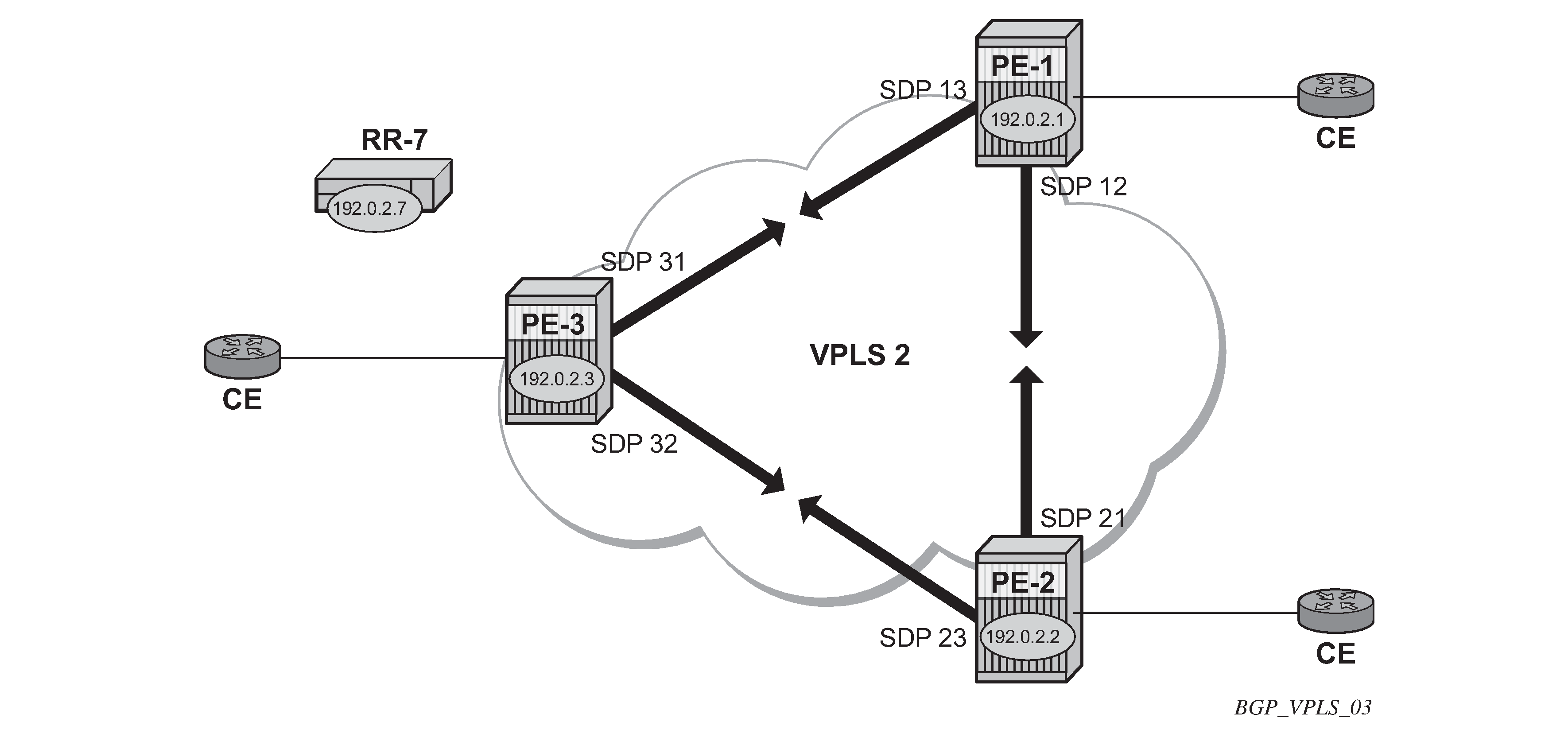
On the PEs, the following SDPs are configured with RSVP transport tunnels.
# on PE-1:
configure {
    service {
        sdp 12 {
            admin-state enable
            description "SDP-PE-1-PE-2_RSVP_BGP"
            delivery-type mpls
            signaling bgp
            far-end {
                ip-address 192.0.2.2
            }
            lsp "LSP-PE-1-PE-2" { }
        }
        sdp 13 {
            admin-state enable
            description "SDP-PE-1-PE-3_RSVP_BGP"
            delivery-type mpls
            signaling bgp
            far-end {
                ip-address 192.0.2.3
            }
            lsp "LSP-PE-1-PE-3" { }
        }
# on PE-2:
configure {
    service {
        sdp 21 {
            admin-state enable
            description "SDP-PE-2-PE-1_RSVP_BGP"
            delivery-type mpls
            signaling bgp
            far-end {
                ip-address 192.0.2.1
            }
            lsp "LSP-PE-2-PE-1" { }
        }
        sdp 23 {
            admin-state enable
            description "SDP-PE-2-PE-3_RSVP_BGP"
            delivery-type mpls
            signaling bgp
            far-end {
                ip-address 192.0.2.3
            }
            lsp "LSP-PE-2-PE-3" { }
        }
# on PE-3:
configure {
    service {
        sdp 31 {
            admin-state enable
            description "SDP-PE-3-PE-1_RSVP_BGP"
            delivery-type mpls
            signaling bgp
            far-end {
                ip-address 192.0.2.1
            }
            lsp "LSP-PE-3-PE-1" { }
        }
        sdp 32 {
            admin-state enable
            description "SDP-PE-3-PE-2_RSVP_BGP"
            delivery-type mpls
            signaling bgp
            far-end {
                ip-address 192.0.2.2
            }
            lsp "LSP-PE-3-PE-2" { }
        }
Pre-provisioned BGP-SDPs can also be used with BGP-VPLS. For reference, they are configured as follows:
# on PE-3:
configure {
    service {
        sdp 332 {
            admin-state enable
            delivery-type mpls
            signaling bgp
            far-end {
                ip-address 192.0.2.2
            }
        }
To create an SDP within a service that uses the RSVP transport tunnel, a pseudowire template is required that has the provisioned-sdp use parameter set. It is also possible to configure the provisioned-sdp prefer parameter, see chapter LDP VPLS Using BGP Auto-Discovery — Prefer Provisioned SDP.
Once again, an SHG is included to prevent forwarding between pseudowires.
The following pseudowire template is provisioned on all PEs:
# on PE-1, PE-2, and PE-3:
configure {
    service {
        pw-template "PW2" {
            pw-template-id 2
            provisioned-sdp use
            split-horizon-group {
                name "VPLS-SHG"
            }
        }
The following output shows the configuration required for a BGP-VPLS service using a pseudowire template configured for using pre-provisioned RSVP-TE SDPs.
# on PE-1:
configure {
    service {
        vpls "VPLS2_PE-1" {
            admin-state enable
            service-id 2
            customer "1"
            bgp 1 {
                route-distinguisher "65536:2"
                route-target {
                    export "target:65536:2"
                    import "target:65536:2"
                }
                pw-template-binding "PW2" {
                }
            }
            bgp-vpls {
                admin-state enable
                maximum-ve-id 100
                ve {
                    name "PE-1"
                    id 1
                }
            }
            sap 1/1/4:2.0 {
            }
        }
The RD and RT extended community values for VPLS 2 are different from the ones in VPLS 1. The VE-ID value for PE-1 can be the same as the one in VPLS 1, but these must be different within the same VPLS instance on the other PEs — PE-2 should not have VE-ID = 1.
On PE-2, the configuration is as follows with the VE-ID value equal to 20, which will result in a label from a different block:
# on PE-2:
configure {
    service {
        vpls "VPLS2_PE-2" {
            admin-state enable
            service-id 2
            customer "1"
            bgp 1 {
                route-distinguisher "65536:2"
                route-target {
                    export "target:65536:2"
                    import "target:65536:2"
                }
                pw-template-binding "PW2" {
                }
            }
            bgp-vpls {
                admin-state enable
                maximum-ve-id 100
                ve {
                    name "PE-2"
                    id 20
                }
            }
            sap 1/1/4:2.0 {
            }
        }
On PE-3, the configuration is as follows with the VE-ID value equal to 3:
# on PE-3:
configure {
    service {
        vpls "VPLS2_PE-3" {
            admin-state enable
            service-id 2
            customer "1"
            bgp 1 {
                route-distinguisher "65536:2"
                route-target {
                    export "target:65536:2"
                    import "target:65536:2"
                }
                pw-template-binding "PW2" {
                }
            }
            bgp-vpls {
                admin-state enable
                maximum-ve-id 100
                ve {
                    name "PE-3"
                    id 3
                }
            }
            sap 1/1/4:2.0 {
            }
        }
The service is operationally up on PE-1, as follows:
[]
A:admin@PE-1# show service id 2 base

===============================================================================
Service Basic Information
===============================================================================
Service Id        : 2                   Vpn Id            : 0
Service Type      : VPLS
MACSec enabled    : no
Name              : VPLS2_PE-1
---snip---

Admin State       : Up                  Oper State        : Up
MTU               : 1514
SAP Count         : 1                   SDP Bind Count    : 2
---snip---

-------------------------------------------------------------------------------
Service Access & Destination Points
-------------------------------------------------------------------------------
Identifier                               Type         AdmMTU  OprMTU  Adm  Opr
-------------------------------------------------------------------------------
sap:1/1/4:2.0                            qinq         1522    1522    Up   Up
sdp:12:4294967292 S(192.0.2.2)           BgpVpls      0       1556    Up   Up
sdp:13:4294967293 S(192.0.2.3)           BgpVpls      0       1556    Up   Up
===============================================================================
* indicates that the corresponding row element may have been truncated.
The SDPs 12 and 13 are the pre-provisioned SDPs on PE-1.
The service is operationally up on PE-2, as follows:
[]
A:admin@PE-2# show service id 2 base

===============================================================================
Service Basic Information
===============================================================================
Service Id        : 2                   Vpn Id            : 0
Service Type      : VPLS
MACSec enabled    : no
Name              : VPLS2_PE-2
---snip---

Admin State       : Up                  Oper State        : Up
MTU               : 1514
SAP Count         : 1                   SDP Bind Count    : 2
---snip---

-------------------------------------------------------------------------------
Service Access & Destination Points
-------------------------------------------------------------------------------
Identifier                               Type         AdmMTU  OprMTU  Adm  Opr
-------------------------------------------------------------------------------
sap:1/1/4:2.0                            qinq         1522    1522    Up   Up
sdp:21:4294967292 S(192.0.2.1)           BgpVpls      0       1556    Up   Up
sdp:23:4294967293 S(192.0.2.3)           BgpVpls      0       1556    Up   Up
===============================================================================
* indicates that the corresponding row element may have been truncated.
The service is operationally up on PE-3, as follows:
[]
A:admin@PE-3# show service id 2 base

===============================================================================
Service Basic Information
===============================================================================
Service Id        : 2                   Vpn Id            : 0
Service Type      : VPLS
MACSec enabled    : no
Name              : VPLS2_PE-3
---snip---

Admin State       : Up                  Oper State        : Up
MTU               : 1514
SAP Count         : 1                   SDP Bind Count    : 2
---snip---

-------------------------------------------------------------------------------
Service Access & Destination Points
-------------------------------------------------------------------------------
Identifier                               Type         AdmMTU  OprMTU  Adm  Opr
-------------------------------------------------------------------------------
sap:1/1/4:2.0                            qinq         1522    1522    Up   Up
sdp:31:4294967293 S(192.0.2.1)           BgpVpls      0       1556    Up   Up
sdp:32:4294967292 S(192.0.2.2)           BgpVpls      0       1556    Up   Up
===============================================================================
* indicates that the corresponding row element may have been truncated.
PE-1 de-multiplexer label calculation
In the case of VPLS 1, all VE-IDs are in the range of a single label block. In the case of VPLS 2, the VE-IDs are in different blocks, for example, the VE-ID 20 is in a different block to VE-IDs 1 and 3.
As the label allocation is block-dependent, multiple label blocks must be advertised by each PE to encompass this.
Consider PE-1’s BGP update NLRIs.
[]
A:admin@PE-1# show router bgp routes l2-vpn rd 65536:2 hunt
===============================================================================
 BGP Router ID:192.0.2.1        AS:65536       Local AS:65536
===============================================================================
---snip---

-------------------------------------------------------------------------------
RIB Out Entries
-------------------------------------------------------------------------------
Route Type     : VPLS
Route Dist.    : 65536:2
VeId           : 1                      Block Size     : 8
Base Offset    : 1                      Label Base     : 524264
Nexthop        : 192.0.2.1
To             : 192.0.2.7
Res. Nexthop   : n/a
Local Pref.    : 100                    Interface Name : NotAvailable
Aggregator AS  : None                   Aggregator     : None
Atomic Aggr.   : Not Atomic             MED            : 0
AIGP Metric    : None                   IGP Cost       : n/a
Connector      : None
Community      : target:65536:2
                 l2-vpn/vrf-imp:Encap=19: Flags=none: MTU=1514: PREF=0
Cluster        : No Cluster Members
Originator Id  : None                   Peer Router Id : 192.0.2.7
Origin         : IGP
AS-Path        : No As-Path
Route Tag      : 0
Neighbor-AS    : n/a
Orig Validation: N/A
Source Class   : 0                      Dest Class     : 0

Route Type     : VPLS
Route Dist.    : 65536:2
VeId           : 1                      Block Size     : 8
Base Offset    : 17                     Label Base     : 524256
Nexthop        : 192.0.2.1
To             : 192.0.2.7
Res. Nexthop   : n/a
Local Pref.    : 100                    Interface Name : NotAvailable
Aggregator AS  : None                   Aggregator     : None
Atomic Aggr.   : Not Atomic             MED            : 0
AIGP Metric    : None                   IGP Cost       : n/a
Connector      : None
Community      : target:65536:2
                 l2-vpn/vrf-imp:Encap=19: Flags=none: MTU=1514: PREF=0
Cluster        : No Cluster Members
Originator Id  : None                   Peer Router Id : 192.0.2.7
Origin         : IGP
AS-Path        : No As-Path
Route Tag      : 0
Neighbor-AS    : n/a
Orig Validation: N/A
Source Class   : 0                      Dest Class     : 0

-------------------------------------------------------------------------------
Routes : 8
===============================================================================
Two NLRIs updates are sent to the route reflector, with the following label parameters:
1. LB = 524264, VBS = 8, VBO = 1
2. LB = 524256, VBS = 8, VBO = 17
PE-2 has a VE-ID of 20. Applying the condition VBO < VE-ID < (VBO+VBS)
-
Update 1: LB = 524264, VBS = 8, VBO = 1
-
VBO < VE-ID for VE-ID = 20 is true
-
VE-ID < (VBO+VBS) for VE-ID = 20 is false.
-
PE-2 cannot choose a label from this block.
-
Update 2: LB = 524256, VBS = 8, VBO = 17
-
VBO < VE-ID for VE-ID = 20 is true
-
VE-ID < (VBO+VBS) for VE-ID = 20 is true.
-
PE-2 chooses label 524256 + 20 - 17 = 524259 (LB + VEID - VBO)
The egress label chosen is verified by examining the egress label toward PE-1 (192.0.2.1) on PE-2.
[]
A:admin@PE-2# show service id 2 sdp

===============================================================================
Services: Service Destination Points
===============================================================================
SdpId            Type     Far End addr    Adm     Opr       I.Lbl     E.Lbl
-------------------------------------------------------------------------------
21:4294967292    BgpVpls  192.0.2.1       Up      Up        524254    524259
23:4294967293    BgpVpls  192.0.2.3       Up      Up        524256    524259
-------------------------------------------------------------------------------
Number of SDPs : 2
-------------------------------------------------------------------------------
===============================================================================
PE-3 has a VE-ID of 3. Applying the condition VBO < VE-ID < (VBO+VBS)
-
Update 1: LB = 524264, VBS = 8, VBO = 1
-
VBO < VE-ID for VE-ID = 3 is true
-
VE-ID < (VBO+VBS) for VE-ID = 3 is true.
-
PE-3 chooses label 524264 + 3 - 1 = 524266 (LB + VEID - VBO)
-
Update 2: LB = 524256, VBS = 8, VBO = 17
-
VBO < VE-ID for VE-ID = 3 is false
-
VE-ID < (VBO+VBS) for VE-ID = 3 is true.
-
PE-3 cannot choose a label from this block.
The egress label chosen is verified by examining the egress label toward PE-1 (192.0.2.1) on PE-3.
[]
A:admin@PE-3# show service id 2 sdp

===============================================================================
Services: Service Destination Points
===============================================================================
SdpId            Type     Far End addr    Adm     Opr       I.Lbl     E.Lbl
-------------------------------------------------------------------------------
31:4294967293    BgpVpls  192.0.2.1       Up      Up        524264    524266
32:4294967292    BgpVpls  192.0.2.2       Up      Up        524259    524256
-------------------------------------------------------------------------------
Number of SDPs : 2
-------------------------------------------------------------------------------
===============================================================================
To illustrate the allocation of label blocks by a PE, against the actual use of the same labels, consider the following. When BGP updates from each PE signal the multiplexer labels in blocks of eight, the allocated label values are added to the in-use pool. First check what label range can be allocated dynamically.
[]
A:admin@PE-1# show router mpls-labels label-range

===============================================================================
Label Ranges
===============================================================================
Label Type      Start Label End Label   Aging       Available   Total
-------------------------------------------------------------------------------
Static          32          18431       -           18400       18400
Dynamic         18432       524287      0           505824      505856
    Seg-Route   0           0           -           0           0
===============================================================================
Verify which labels in the dynamic range are in use. The label pool of PE-1 can be verified as per the following output which shows labels used along with the associated protocol:
[]
A:admin@PE-1# show router mpls-labels label 18432 524287 in-use

=================================================================
MPLS Labels from 18432 to 524287 (In-use)
=================================================================
Label               Label Type          Label Owner
-----------------------------------------------------------------
524256              dynamic             BGP
524257              dynamic             BGP
524258              dynamic             BGP
524259              dynamic             BGP
524260              dynamic             BGP
524261              dynamic             BGP
524262              dynamic             BGP
524263              dynamic             BGP
524264              dynamic             BGP
524265              dynamic             BGP
524266              dynamic             BGP
524267              dynamic             BGP
524268              dynamic             BGP
524269              dynamic             BGP
524270              dynamic             BGP
524271              dynamic             BGP
524272              dynamic             BGP
524273              dynamic             BGP
524274              dynamic             BGP
524275              dynamic             BGP
524276              dynamic             BGP
524277              dynamic             BGP
524278              dynamic             BGP
524279              dynamic             BGP
524280              dynamic             RSVP
524281              dynamic             RSVP
524282              dynamic             ILDP
524283              dynamic             ILDP
524284              dynamic             ILDP
524285              dynamic             ILDP
524286              dynamic             ILDP
524287              dynamic             ILDP
-----------------------------------------------------------------
In-use labels (Owner: All) in specified range   : 32
In-use labels in entire range                   : 32
=================================================================
This shows that 24 labels have been allocated for use by BGP. Of this number, 16 labels have been allocated for use by PEs within VPLS 2 to communicate with PE-1, the blocks with label base 524256 and with label base 524264.
There are only two neighboring PEs within this VPLS instance, so only two labels will ever be used in the data plane for traffic destined for PE-1. These are 524259 and 524266. The remaining labels have no PE with the associated VE-ID that can use them.
Once again, this case emphasizes that to reduce label wastage, contiguous VE-IDs in the range (N..N+7) per VPLS should be chosen, where N>0.
Conclusion
BGP-VPLS allows the delivery of Layer 2 VPN services to customers where BGP is commonly used. The examples presented in this chapter show the configuration of BGP-VPLS together with the associated show outputs which can be used for verification and troubleshooting.