PIM Snooping for IPv4 in EVPN-MPLS Services
This chapter provides information about PIM snooping for IPv4 in EVPN-MPLS services.
Topics in this chapter include:
Applicability
This chapter was initially written based on SR OS Release 15.0.R5, but the CLI in the current edition corresponds to SR OS Release 23.7.R1. PIM snooping for IPv4 is supported in EVPN-MPLS services in SR OS Release 15.0.R1, and later. PIM snooping in single-active multi-homing mode without ESI label is supported in SR OS Release 15.0.R1, and later, whereas PIM snooping in single-active multi-homing mode with ESI label is supported in SR OS Release 15.0.R4, and later. PIM snooping in all-active multi-homing mode is supported in SR OS Release 15.0.R4, and later. Data-driven PIM state synchronization is supported in SR OS Release 15.0.R4, and later.
Overview
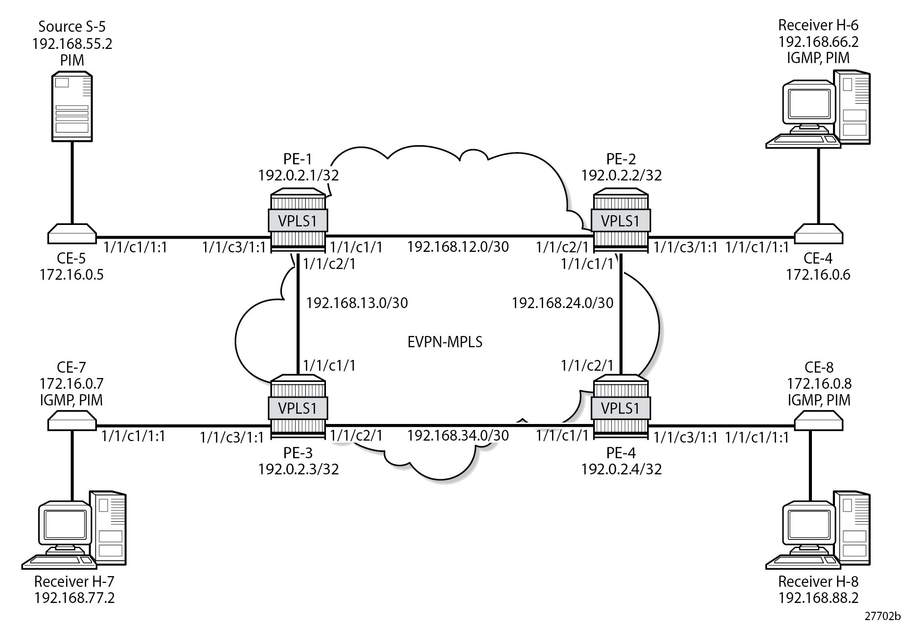
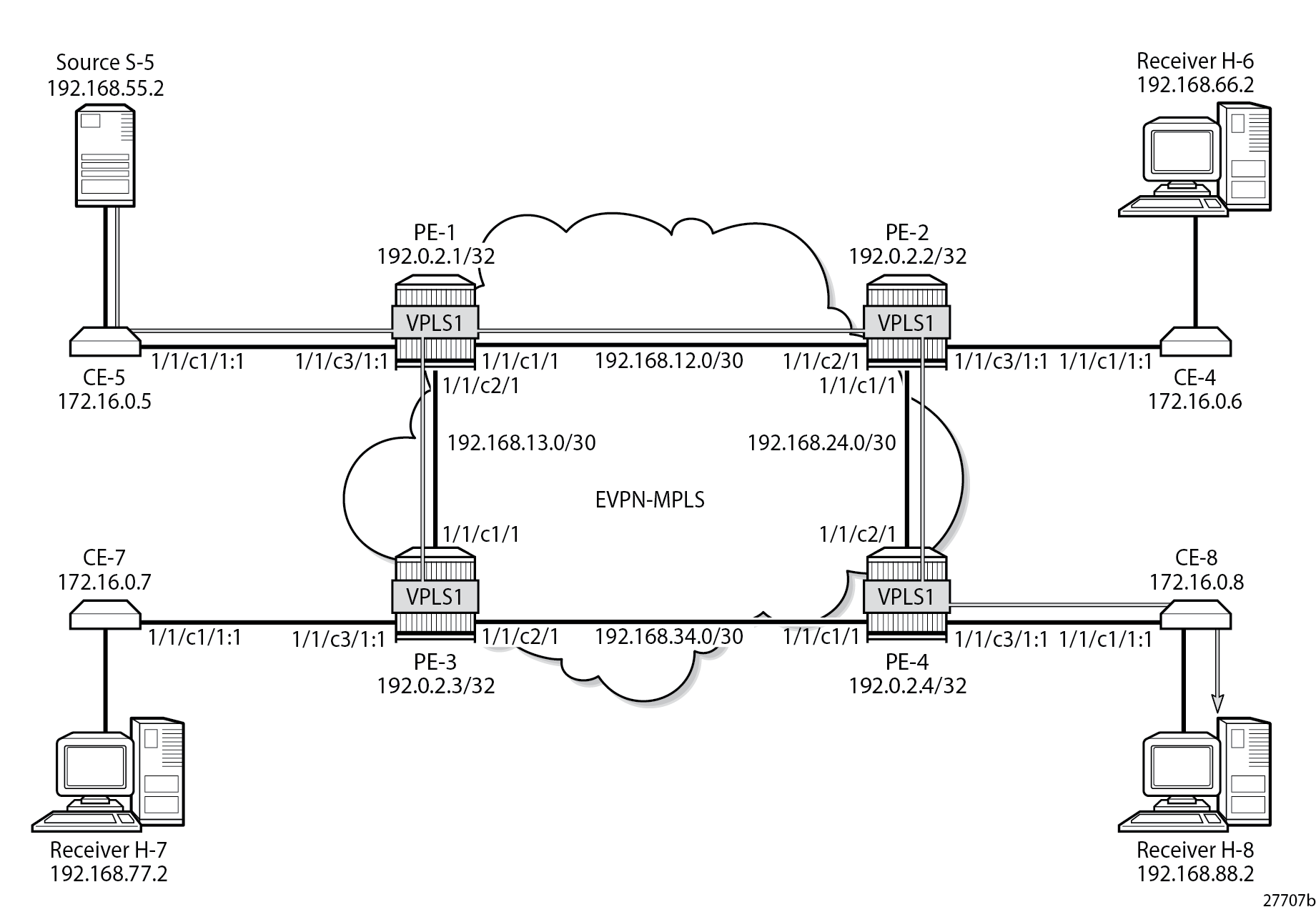
Multicast in VPLS without PIM Snooping shows the example topology with four CEs that have IGMP and PIM enabled (L3) and four PEs configured with VPLS 1 (L2). Source-specific multicast is used in this example. The following description applies to all VPLSs, with or without EVPN.
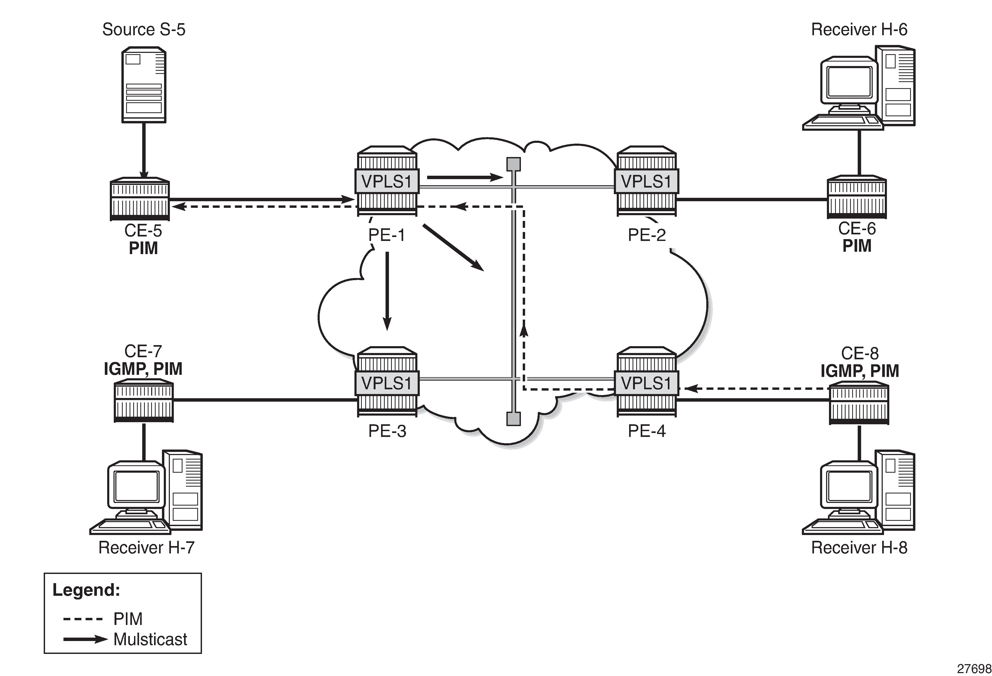
The VPLS emulates a LAN interconnecting sites with L3-capable devices that use PIM to join or leave multicast groups. When receiver H-8 sends an IGMP report message to join a multicast group, CE-8 sends a PIM join message to CE-5. The PEs forward the PIM message without learning any PIM-related information, such as which CE sent the PIM join and for which multicast group.
The source S-5 is sending the multicast stream to CE-5. When CE-5 receives a PIM join message for this multicast group from CE-8, it forwards the multicast stream to CE-8. By default, all PEs flood the multicast stream on all their connections in the VPLS domain, regardless of whether a PIM join was received from that connection. L2 flooding is not aware of the PIM join/prune messages from the L3 edge routers, resulting in an inefficient use of network resources. To avoid this L2 flooding, PIM snooping can be enabled in the VPLS by the following command:
configure {
    service {
        vpls "VPLS 1" {
            pim-snooping ?

 pim-snooping

 apply-groups          - Apply a configuration group at this level
 apply-groups-exclude  - Exclude a configuration group at this level
 group-policy          - Group policy name
 hold-time             - Duration that allows the PIM-snooping switch to snoop all the PIM states in the VPLS
 ipv4                  + Enter the ipv4 context
 ipv6                  + Enter the ipv6 context

configure {
    service {
        vpls "VPLS 1" {
            pim-snooping {
            ipv4 ?

 ipv4

 admin-state           - Administrative state of snooping for multicast traffic
 apply-groups          - Apply a configuration group at this level
 apply-groups-exclude  - Exclude a configuration group at this level
The default mode is proxy, but PIM snooping can also use snooping mode, depending on the information in the received PIM hello messages. In snooping mode, the PE does not modify the PIM messages; in proxy mode, the PE terminates incoming PIM messages and generates its own PIM messages.
PIM snooping is used for router multicast registration, whereas IGMP snooping is used for host/client multicast registration. IGMP snooping in EVPN-MPLS services is described in chapter P2MP mLDP Tunnels for BUM Traffic in EVPN-MPLS Services. Optionally, PIM snooping and IGMP snooping can be enabled simultaneously.
With PIM enabled, the CEs send PIM hello messages to the well-known multicast address for PIM, 224.0.0.13. PIM hello messages are used to form PIM neighbors and can be used to form the Forwarding Database (FDB). With PIM snooping enabled in the VPLS in the PEs, the PEs snoop PIM messages. The PEs only forward multicast traffic downstream when required, as determined from the received PIM messages. This provides a more efficient use of network resources.
PIM snooping states in a PE are maintained per VPLS instance. When PIM snooping is enabled, IP multicast traffic to a multicast group that is not learned via snooping is dropped by default, unless it is received from a directly connected source.
PIM Snooping in Snooping Mode
Multicast in VPLS with PIM Snooping in Snooping Mode shows that the multicast stream is not flooded in PE-1 when PIM snooping is enabled and operating in snooping mode.
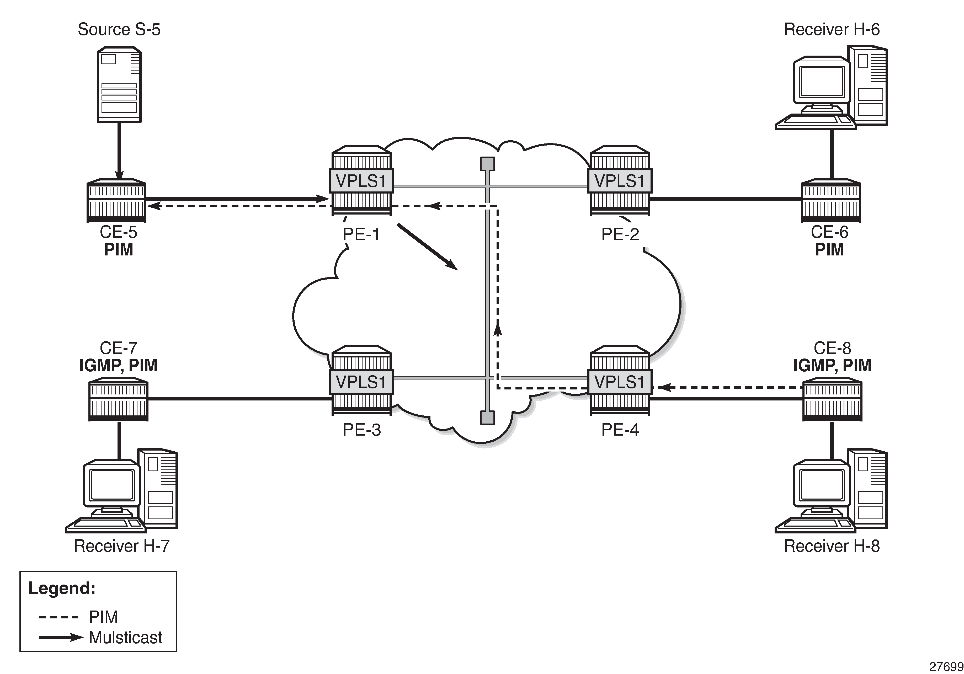
When H-8 sends an IGMP report message to join the multicast stream from source S-5 to CE-8, CE-8 sends a PIM join message to CE-5. PE-4 snoops the PIM join message and builds the FDB. PE-4 forwards the PIM join message to PE-1 by matching the upstream neighbor address in the join with the neighbor database. PE-1 snoops the PIM join message, builds its Multicast Forwarding Information Base (MFIB), and performs a similar lookup in its FDB. PE-1 forwards the PIM join to CE-5. The Source Path Tree (SPT) between receiver CE-8 and sender CE-5 is now built and CE-5 forwards multicast data frames to CE-8. PE-1 does not flood multicast frames, but forwards them to CE-8 only, based on the MFIB.
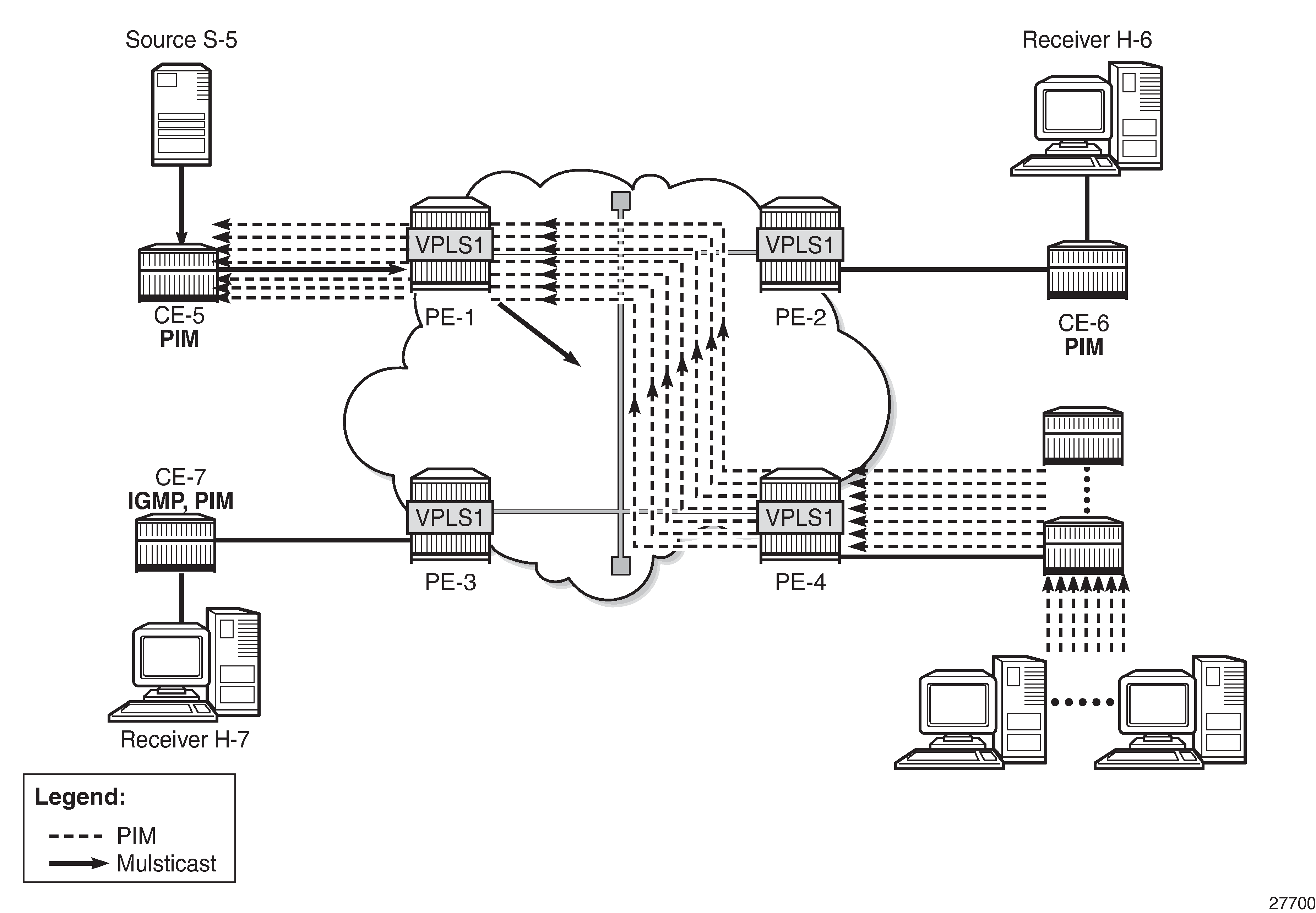
Multicast in VPLS with PIM Snooping in Snoop Mode – Multiple CEs shows how the number of PIM messages in the control plane increases when multiple client CEs are connected to PE-4.
PIM Snooping in Proxy Mode
When H-8 sends an IGMP report message to join a multicast stream, CE-8 again sends a PIM join message to CE-5. PE-4 terminates the incoming PIM join message and generates its own PIM join message using CE-5 as the source address, learned from the PIM hello messages. PE-4 builds its MFIB and sends a new PIM join message to S-5. PE-1 terminates the incoming PIM join message and builds its MFIB. PE-1 generates its own PIM join message using CE-5 as the source address. PE-1 forwards the PIM join to CE-5. The SPT between CE-8 and CE-5 is now built and the multicast stream flows from source S-5 to receiver H-8. No multicast traffic is sent to CE-6 and CE-7, because they do not have receivers attached that joined the multicast stream.
The default mode for PIM snooping is proxy mode.
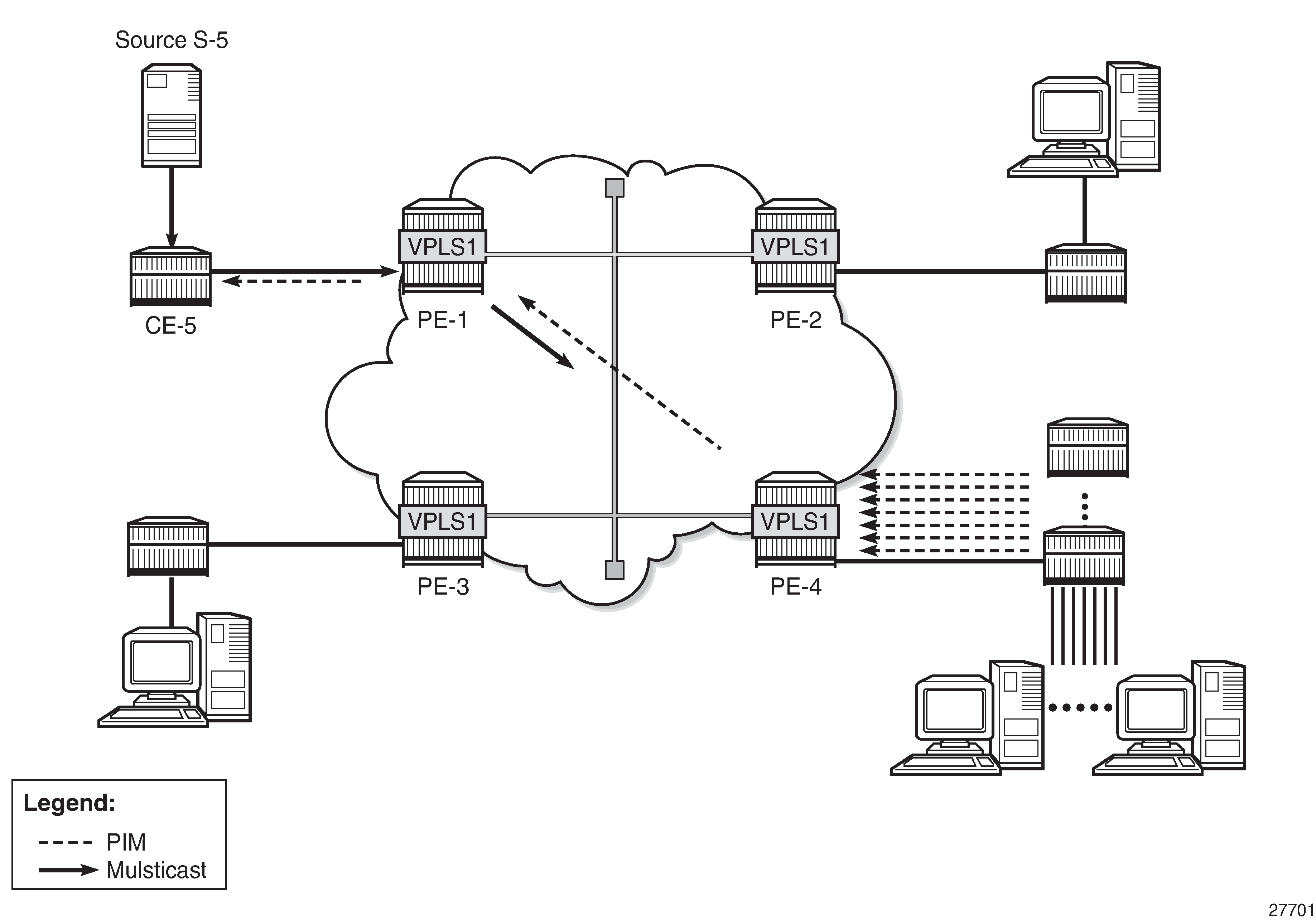
Multicast in VPLS with PIM Snooping in Proxy Mode - Multiple CEs shows that the number of PIM messages in the control plane does not increase when multiple client CEs are connected to PE-4, compared to snooping mode.
PIM snooping in proxy mode can be configured with a delay to avoid existing traffic interruption. PIM snooping in proxy mode does not program the MFIB until a hold timer has expired. This hold time is useful in the following cases:
PIM snooping being enabled on the VPLS
PIM snooping states being manually cleared by an operator
When the hold timer is started, but not expired yet, multicast traffic is flooded in the VPLS as if PIM snooping was not enabled. VPLS flooding ensures flow delivery during the hold time.
PIM Snooping in VPLS with EVPN-MPLS
PIM snooping in an EVPN-MPLS service supports the following:
Regular PIM snooping on SAPs/SDP-bindings
PIM messages received on EVPN-MPLS endpoints are forwarded to SAPs/SDP-bindings.
IP multicast traffic received on an EVPN-MPLS binding is forwarded to SAPs/SDP-bindings from which a PIM join was received, or to ports configured as mrouter ports.
The EVPN-MPLS endpoints are treated as a single PIM interface:
IP multicast traffic and PIM messages received on an EVPN-MPLS endpoint are not forwarded to other EVPN-MPLS endpoints (split-horizon).
Hello and join/prune messages from SAPs/SDP-bindings are forwarded to all EVPN-MPLS destinations.
When a hello message is received from one PIM neighbor on an EVPN-MPLS destination, the single interface representing all EVPN-MPLS destinations has that neighbor.
Individual destinations appear in the MFIB, but the information for each EVPN-MPLS destination entry is identical.
If a Point-to-Multipoint (P2MP) mLDP provider tunnel is configured:
If the PE is the root node of a P2MP LSP that is up, PIM messages and IP multicast traffic are only forwarded over the P2MP Label Switched Path (LSP) instead of being sent to the EVPN-MPLS endpoints. Therefore, the P2MP leaves must match the EVPN-MPLS endpoints, in this case, PE-2, PE-3, and PE-4.
If the PE is a leaf node of a P2MP LSP, it sends PIM messages and IP multicast traffic over its EVPN-MPLS endpoints.
The PEs can expect to receive IP multicast traffic and PIM messages from leaf nodes over their EVPN-MPLS endpoints, or over the P2MP LSPs for traffic from root nodes.
PIM snooping is supported in inter-AS model B and inter-AS model C, as for IGMP snooping.
All-active and single-active EVPN multi-homing are supported.
Multi-chassis Synchronization (MCS) of PIM snooping state is supported on SAPs and spoke-SDPs in dual-homing.
The active (Designated Forwarder (DF)) PE sends the PIM states to the backup non-DF (NDF) PE.
In case of failure, the backup PE has the PIM states already, and the multicast traffic path can be re-established fast without any need to wait for PIM states to be snooped.
A sync-tag is configured on the ports or SDPs that need to be synchronized on both PEs.
MCS PIM snooping is restricted to two peers, even though MCS supports more peers for other types of information. An error is raised when attempting to configure a sync-tag on the same port or SDP to more than one peer.
PIM snooping is supported for both IPv4 and IPv6 multicast. PIM snooping for IPv6 uses MAC-based forwarding by default, and can be configured to use (S,G)-based forwarding.
PIM snooping is transparent to the underlying tunnel. PIM snooping works with RSVP, LDP, SR-ISIS, SR-OSPF, SR-TE, BGP, and MPLSoUDP.
PIM snooping is not supported with routed VPLS with EVPN-MPLS, and its configuration is blocked.
Configuration
Example Topology shows the example topology. Source S-5 sends multicast streams to CE-5, which forwards those only after a PIM join message has been received. An mLDP P2MP LSP is used to distribute the multicast from the root node PE-1 to the other PEs. All CEs have PIM enabled and the receiving CEs (CE-6, CE-7, and CE-8) have IGMP configured on the interface toward the receivers (H-6, H-7, and H-8). EVPN-MPLS VPLS 1 is configured on the PEs. Initially, PIM snooping is disabled in the VPLS. Receiver H-8 joins multicast group 232.1.1.1 from source S-5.
The initial configuration includes the following:
Cards, MDAs
Ports
Ports between PEs are network ports with null encapsulation
Ports between CEs and PEs are hybrid ports with dot1q encapsulation
IS-IS as IGP between the PEs (alternatively, OSPF can be used)
LDP between the PEs
BGP with address family EVPN between the PEs. PE-2 is the route reflector (RR). The BGP configuration on RR PE-2 is as follows:
On PE-2:
configure {
    router "Base" {
        autonomous-system 64496
        bgp {
            rapid-withdrawal true
            ebgp-default-reject-policy {
                import false
                export false
            }
            rapid-update {
                evpn true
            }
            group "INTERNAL" {
                type internal
                family {
                    evpn true
                }
                cluster {
                    cluster-id 192.0.2.2
                }
            }
            neighbor "192.0.2.1" {
                group "INTERNAL"
            }
            neighbor "192.0.2.3" {
                group "INTERNAL"
            }
            neighbor "192.0.2.4" {
                group "INTERNAL"
            }
        }
    }
}
EVPN-MPLS VPLS without PIM Snooping
VPLS 1 is configured with EVPN-MPLS in the PEs. By default, PIM snooping is disabled. PE-1 is configured as root-and-leaf node for the P2MP mLDP multicast tree, while the other three PEs have the default no root-and-leaf configured, so they are leaf-only nodes. The configuration of VPLS 1 on PE-1 is as follows:
On PE-1:
configure {
    service {
        vpls "VPLS 1" {
            admin-state enable
            service-id 1
            customer "1"
            bgp 1 { }
            bgp-evpn {
                evi 1
                mpls 1 {
                    admin-state enable
                    ingress-replication-bum-label true
                    auto-bind-tunnel {
                        resolution any
                    }
                }
            }
            sap 1/1/c3/1:1 { }
            provider-tunnel {
                inclusive {
                    admin-state enable
                    owner bgp-evpn-mpls
                    root-and-leaf true
                    mldp
                }
            }
        }
    }
}
A P2MP mLDP multicast tree is created from root node PE-1 to the leaf nodes. On the root node PE-1, an SDP of type VplsPmsi is auto-created:
[/]
A:admin@PE-1# show service id 1 base

===============================================================================
Service Basic Information
===============================================================================
Service Id        : 1                   Vpn Id            : 0
Service Type      : VPLS
---snip---
-------------------------------------------------------------------------------
Service Access & Destination Points
-------------------------------------------------------------------------------
Identifier                               Type         AdmMTU  OprMTU  Adm  Opr
-------------------------------------------------------------------------------
sap:1/1/c3/1:1                           q-tag        8936    8936    Up   Up
sdp:32767:4294967294 SB(not applicable)  VplsPmsi     9782    9782    Up   Up
===============================================================================
* indicates that the corresponding row element may have been truncated.
The following inclusive provider tunnel is created on root node PE-1:
[/]
A:admin@PE-1# show service id 1 provider-tunnel

===============================================================================
Service Provider Tunnel Information
===============================================================================
Type               : inclusive          Root and Leaf      : enabled
Admin State        : enabled            Data Delay Intvl   : 15 secs
PMSI Type          : ldp                LSP Template       :
Remain Delay Intvl : 0 secs             LSP Name used      : 8193
PMSI Owner         : bgpEvpnMpls
Oper State         : up                 Root Bind Id       : 32767
-------------------------------------------------------------------------------
Type               : selective          Wildcard SPMSI     : disabled
Admin State        : disabled           Data Delay Intvl   : 3 secs
PMSI Type          : none               Max P2MP SPMSI     : 10
PMSI Owner         : none
===============================================================================
When a P2MP mLDP provider tunnel is configured, the root node forwards PIM messages and IP multicast traffic over the provider tunnel instead of over the EVPN-MPLS endpoints. However, the leaf nodes of a P2MP mLDP provider tunnel send PIM messages and IP multicast traffic over the EVPN-MPLS endpoints.
The following P2MP mLDP bindings are active on root node PE-1: one toward PE-2 via port 1/1/c1/1 and one toward PE-3 via port 1/1/c2/1.
[/]
A:admin@PE-1# show router ldp bindings active p2mp opaque-type generic ipv4

===============================================================================
LDP Bindings (IPv4 LSR ID 192.0.2.1)
             (IPv6 LSR ID ::)
===============================================================================
Label Status:
        U - Label In Use, N - Label Not In Use, W - Label Withdrawn
        WP - Label Withdraw Pending, BU - Alternate For Fast Re-Route
        e - Label ELC
FEC Flags:
        LF - Lower FEC, UF - Upper FEC, M - Community Mismatch,
        BA - ASBR Backup FEC
===============================================================================
LDP Generic IPv4 P2MP Bindings (Active)
===============================================================================
P2MP-Id                                     Interface
RootAddr                                    Op
IngLbl                                      EgrLbl
EgrNH                                       EgrIf/LspId
-------------------------------------------------------------------------------
8193                                        73728
192.0.2.1                                   Push
  --                                        524281
192.168.12.2                                1/1/c1/1

8193                                        73728
192.0.2.1                                   Push
  --                                        524281
192.168.13.2                                1/1/c2/1

-------------------------------------------------------------------------------
No. of Generic IPv4 P2MP Active Bindings: 2
===============================================================================
The following P2MP mLDP bindings are active on PE-2. PE-2 is a leaf node (pop operation) and a transit node for traffic toward PE-4 (swap operation):
[/]
A:admin@PE-2# show router ldp bindings active p2mp opaque-type generic ipv4

===============================================================================
---snip---
===============================================================================
LDP Generic IPv4 P2MP Bindings (Active)
===============================================================================
P2MP-Id                                     Interface
RootAddr                                    Op
IngLbl                                      EgrLbl
EgrNH                                       EgrIf/LspId
-------------------------------------------------------------------------------
8193                                        73728
192.0.2.1                                   Pop
524281                                        --
  --                                          --

8193                                        73728
192.0.2.1                                   Swap
524281                                      524281
192.168.24.2                                1/1/c1/1

-------------------------------------------------------------------------------
No. of Generic IPv4 P2MP Active Bindings: 2
===============================================================================
PE-3 and PE-4 are leaf nodes, so there is a pop operation. The active P2MP LDP binding on PE-4 is the following. A similar P2MP LDP binding occurs on PE-3.
[/]
A:admin@PE-4# show router ldp bindings active p2mp opaque-type generic ipv4
===============================================================================
---snip---
===============================================================================
LDP Generic IPv4 P2MP Bindings (Active)
===============================================================================
P2MP-Id Interface
RootAddr Op
IngLbl EgrLbl
EgrNH EgrIf/LspId
-------------------------------------------------------------------------------
8193 73728
192.0.2.1 Pop
524281 --
-- --
-------------------------------------------------------------------------------
No. of Generic IPv4 P2MP Active Bindings: 1
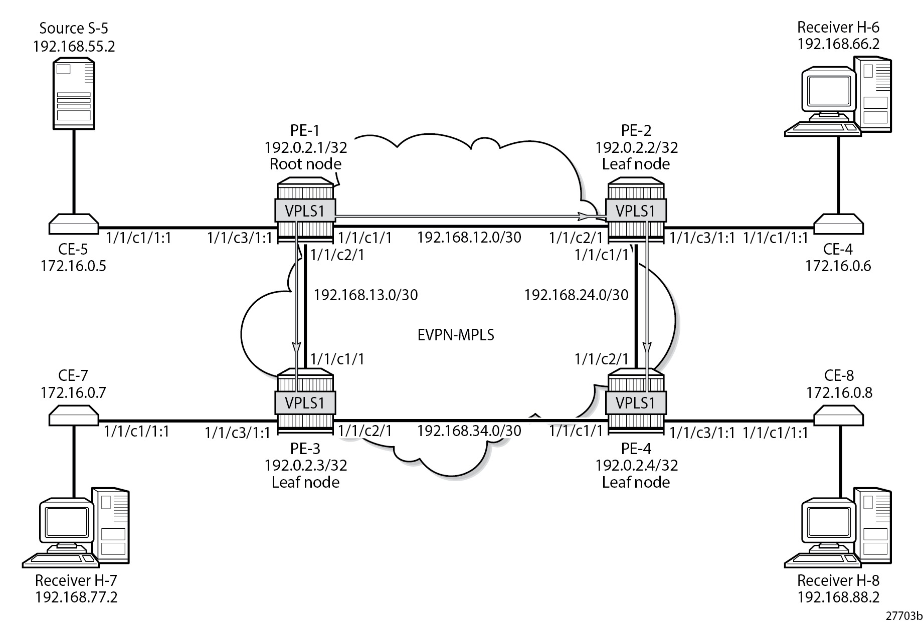
===============================================================================P2MP mLDP Multicast Tree shows the mLDP multicast tree. Multicast traffic from source S-5 uses the mLDP multicast tree from PE-1 to both PE-2 and PE-3. PE-2 is a transit node for multicast traffic to PE-4, and also a leaf node. PE-3 and PE-4 are leaf nodes.
CE-6, CE-7, and CE-8 have IGMP enabled on the interface toward the receiver and PIM enabled on all interfaces. The configuration on CE-8 is as follows:
On CE-8:
configure {
    router "Base" {
        interface "int-CE-8-H-8" {
            port 1/1/c2/1
            ipv4 {
                primary {
                    address 192.168.88.1
                    prefix-length 24
                }
            }
        }
        interface "int-CE-8-PE-4" {
            port 1/1/c1/1:1
            ipv4 {
                primary {
                    address 172.16.0.8
                    prefix-length 16
                }
            }
        }
        interface "system" {
            ipv4 {
                primary {
                    address 192.0.2.8
                    prefix-length 32
                }
            }
        }
        static-routes {
            route 192.168.55.0/30 route-type unicast {
                next-hop "172.16.0.5" {
                    admin-state enable
                }
            }
        }
        pim {
            apply-to all
        }
        igmp {
            interface "int-CE-8-H-8" { }
        }
    }
}
The static route is required on the receiving CEs for the PIM join/prune messages to reach the multicast source S-5 with IP address 192.168.55.2; only IP subnet 172.16.0.0/16 can be reached via the VPLS.
CE-5 has PIM enabled and static routes configured to reach the receiving hosts, as follows:
On CE-5:
configure {
    router "Base" {
        interface "int-CE-5-PE-1" {
            port 1/1/c1/1:1
            ipv4 {
                primary {
                    address 172.16.0.5
                    prefix-length 16
                }
            }
        }
        interface "int-CE-5-S-5" {
            port 1/1/c3/1
            ipv4 {
                primary {
                    address 192.168.55.1
                    prefix-length 30
                }
            }
        }
        interface "system" {
            ipv4 {
                primary {
                    address 192.0.2.5
                    prefix-length 32
                }
            }
        }
        static-routes {
            route 192.168.66.0/24 route-type unicast {
                next-hop "172.16.0.6" {
                    admin-state enable
                }
            }
            route 192.168.77.0/24 route-type unicast {
                next-hop "172.16.0.7" {
                    admin-state enable
                }
            }
            route 192.168.88.0/24 route-type unicast {
                next-hop "172.16.0.8" {
                    admin-state enable
                }
            }
        }
        pim {
            apply-to all
        }
    }
}
The PIM neighbors of CE-5 are the receiving CEs: CE-6, CE-7, and CE-8, as follows:
[/]
A:admin@CE-5# show router pim neighbor

===============================================================================
PIM Neighbor ipv4
===============================================================================
Interface               Nbr DR Prty     Up Time       Expiry Time     Hold Time
   Nbr Address
-------------------------------------------------------------------------------
int-CE-5-PE-1           1               0d 00:00:39   0d 00:01:38     105
   172.16.0.6
int-CE-5-PE-1           1               0d 00:00:28   0d 00:01:30     105
   172.16.0.7
int-CE-5-PE-1           1               0d 00:00:14   0d 00:01:32     105
   172.16.0.8
-------------------------------------------------------------------------------
Neighbors : 3
===============================================================================
H-8 Joins Group (192.168.55.2, 232.1.1.1) and PIM Snooping is Disabled shows that receiver H-8 sends an IGMP report to CE-8 and CE-8 sends a PIM join message to CE-5 via PE-4. PE-4 floods the PIM join message to all PEs, and the message is not snooped by any intermediate PE.

Alternatively, a static multicast group can be configured on IGMP interface int-CE-8-H-8 for multicast group (192.168.55.2, 232.1.1.1), as follows:
On CE-8:
configure {
    router "Base" {
        igmp {
            interface "int-CE-8-H-8" {
                ssm-translate {
                    group-range start 232.0.0.0 end 232.255.255.255 {
                        source 192.168.55.2 { }
                    }
                }
                static {
                    group 232.1.1.1 {
                        source 192.168.55.2 { }
                    }
                }
            }
        }
    }
}
CE-8 sends the following PIM join message for multicast group (192.168.55.2, 232.1.1.1) to upstream IP address 172.16.0.5 on CE-5:
1 2023/08/10 22:51:38.087 CEST MINOR: DEBUG #2001 Base PIM[Instance 1 Base]
"PIM[Instance 1 Base]: Join/Prune
[000 00:17:08.130] PIM-TX ifId 3 ifName int-CE-8-PE-4 0.0.0.0 -> 224.0.0.13 Length: 34
PIM Version: 2 Msg Type: Join/Prune Checksum: 0x4828
Upstream Nbr IP : 172.16.0.5 Resvd: 0x0, Num Groups 1, HoldTime 210
Group: 232.1.1.1/32 Num Joined Srcs: 1, Num Pruned Srcs: 0
Joined Srcs:
192.168.55.2/32 Flag S  <S,G>

"
Multicast stream 232.1.1.1 is sent from source S-5 to CE-5. When CE-5 has received the PIM join message, it floods the multicast stream to PE-1. Root node PE-1 sends the multicast stream to both PE-2 and PE-3. PE-2 forwards the multicast stream to PE-4 and to CE-6; PE-3 forwards the stream to CE-7, and PE-4 forwards to CE-8. The following PIM group for group address 232.1.1.1 is joined on CE-8:
[/]
A:admin@CE-8# show router pim group detail

===============================================================================
PIM Source Group ipv4
===============================================================================
Group Address      : 232.1.1.1
Source Address     : 192.168.55.2
RP Address         : 0
Advt Router        :
Flags              :                    Type               : (S,G)
Mode               : sparse
MRIB Next Hop      : 172.16.0.5
MRIB Src Flags     : remote
Keepalive Timer    : Not Running
Up Time            : 0d 00:02:54        Resolved By        : rtable-u

Up JP State        : Joined             Up JP Expiry       : 0d 00:00:05
Up JP Rpt          : Not Joined StarG   Up JP Rpt Override : 0d 00:00:00

Register State     : No Info
Reg From Anycast RP: No

Rpf Neighbor       : 172.16.0.5
Incoming Intf      : int-CE-8-PE-4
Outgoing Intf List : int-CE-8-H-8

Curr Fwding Rate   : 9751.560 kbps
Forwarded Packets  : 71591              Discarded Packets  : 0
Forwarded Octets   : 106097862          RPF Mismatches     : 0
Spt threshold      : 0 kbps             ECMP opt threshold : 7
Admin bandwidth    : 1 kbps
-------------------------------------------------------------------------------
Groups : 1
===============================================================================
CE-8 forwards the multicast stream to outgoing interface int-CE-8-H-8 toward receiver H-8, while CE-6 and CE-7 drop the traffic.
The following port statistics show that the incoming traffic on port 1/1/c3/1 on PE-1 is forwarded to port 1/1/c1/1 to PE-2 and to port 1/1/c2/1 to PE-3:
[/]
A:admin@PE-1# show port 1/1/c1/1 statistics

===============================================================================
Port Statistics on Slot 1
===============================================================================
Port                        Ingress Packets                  Ingress Octets
Id                           Egress Packets                   Egress Octets
-------------------------------------------------------------------------------
1/1/c1/1                                 37                            3703
                                      27933                        42354073
===============================================================================

[/]
A:admin@PE-1# show port 1/1/c2/1 statistics

===============================================================================
Port Statistics on Slot 1
===============================================================================
Port                        Ingress Packets                  Ingress Octets
Id                           Egress Packets                   Egress Octets
-------------------------------------------------------------------------------
1/1/c2/1                                 33                            3356
                                      27932                        42354034
===============================================================================

[/]
A:admin@PE-1# show port 1/1/c3/1 statistics

===============================================================================
Port Statistics on Slot 1
===============================================================================
Port                        Ingress Packets                  Ingress Octets
Id                           Egress Packets                   Egress Octets
-------------------------------------------------------------------------------
1/1/c3/1                              27901                        41961676
                                          4                             304
===============================================================================
Besides the multicast traffic, signaling messages (such as IS-IS or BGP) are sent, which explains the other counters on the ports being different from zero.
A similar result occurs on PE-2, where incoming traffic from PE-1 is forwarded to PE-4 and to CE-6.
The following port statistics on CE-6 show that the incoming traffic on port 1/1/c1/1 from PE-2 is not forwarded to port 1/1/c2/1 to H-6:
[/]
A:admin@CE-6# show port 1/1/c1/1 statistics
===============================================================================
Port Statistics on Slot 1
===============================================================================
Port Ingress Packets Ingress Octets
Id Egress Packets Egress Octets
-------------------------------------------------------------------------------
1/1/c1/1 27946 42025072
1 76
===============================================================================
[/]
A:admin@CE-6# show port 1/1/c2/1 statistics
===============================================================================
Port Statistics on Slot 1
===============================================================================
Port Ingress Packets Ingress Octets
Id Egress Packets Egress Octets
-------------------------------------------------------------------------------
1/1/c2/1 0 0
2 136
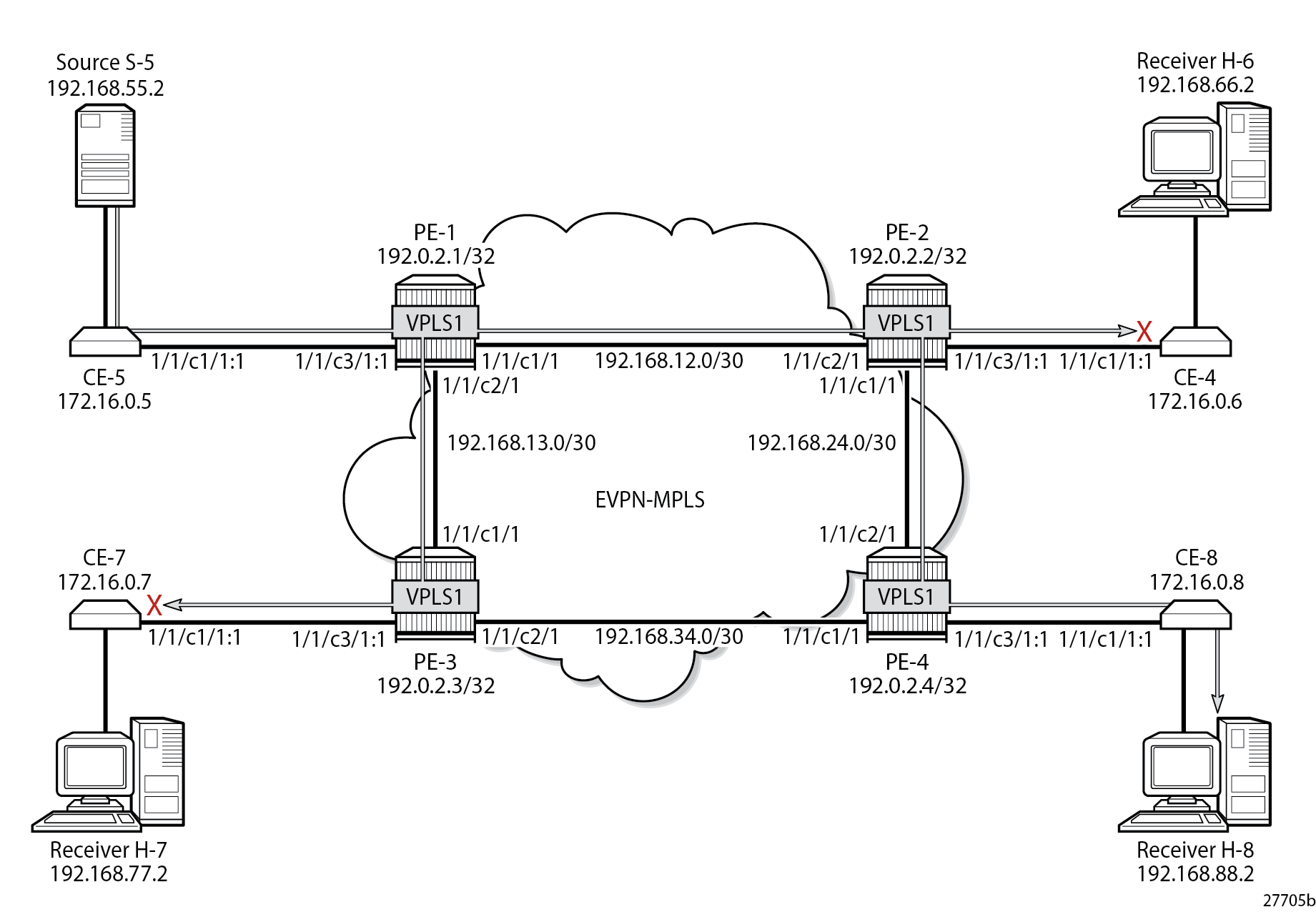
===============================================================================Without PIM snooping, multicast streams are forwarded to CEs that drop them, which wastes resources. Multicast Stream (192.168.55.2, 232.1.1.1) with PIM Snooping Disabled shows the multicast data streams with receiver H-8 joined and PIM snooping disabled.
EVPN-MPLS VPLS with PIM Snooping Enabled
PIM snooping is enabled on all PEs as follows:
configure {
    service {
        vpls "VPLS 1" {
            pim-snooping { }
        }
    }
}
The default mode for PIM snooping is proxy mode, which allows the intermediate PEs to terminate the incoming PIM join or prune messages and create their own PIM join or prune message to be sent toward CE-5, as shown in H-8 Joins (192.168.55.2, 232.1.1.1) and PIM Snooping is Enabled in Proxy Mode:
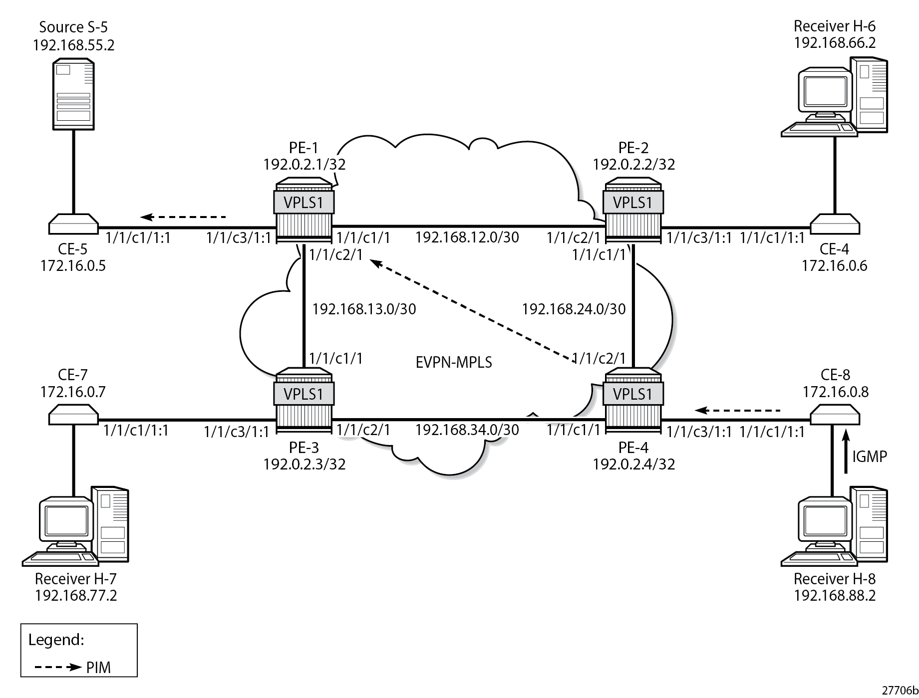
PE-4 receives the following PIM join message for multicast group (192.168.55.2, 232.1.1.1) from CE-8 to CE-5 on SAP 1/1/c3/1:1:
17 2023/08/10 22:59:27.162 CEST MINOR: DEBUG #2001 Base PIM[vpls 1 ]
"PIM[vpls 1 ]: Join/Prune
[000 00:24:58.740] PIM-RX ifId 1 ifName SAP:1/1/c3/1:1 172.16.0.8 -> 224.0.0.13 Length: 34
PIM Version: 2 Msg Type: Join/Prune Checksum: 0x4828
Upstream Nbr IP : 172.16.0.5 Resvd: 0x0, Num Groups 1, HoldTime 210
Group: 232.1.1.1/32 Num Joined Srcs: 1, Num Pruned Srcs: 0
Joined Srcs:
192.168.55.2/32 Flag S  <S,G>

"
PE-4 sends the following PIM join message for multicast group (192.168.55.2, 232.1.1.1) to CE-5 on interface EVPN-MPLS:
18 2023/08/10 22:59:27.162 CEST MINOR: DEBUG #2001 Base PIM[vpls 1 ]
"PIM[vpls 1 ]: Join/Prune
[000 00:24:58.740] PIM-TX ifId 1071394 ifName EVPN-MPLS 0.0.0.0 -> 224.0.0.13 Length: 34
PIM Version: 2 Msg Type: Join/Prune Checksum: 0x4828
Upstream Nbr IP : 172.16.0.5 Resvd: 0x0, Num Groups 1, HoldTime 210
Group: 232.1.1.1/32 Num Joined Srcs: 1, Num Pruned Srcs: 0
Joined Srcs:
192.168.55.2/32 Flag S  <S,G>

"
In a similar way, PE-1 terminates this PIM join message and sends the following PIM join message for multicast group (192.168.55.2, 232.1.1.1) to CE-5 on SAP 1/1/c3/1:1.
19 2023/08/10 22:59:27.159 CEST MINOR: DEBUG #2001 Base PIM[vpls 1 ]
"PIM[vpls 1 ]: Join/Prune
[000 00:25:12.500] PIM-TX ifId 1 ifName SAP:1/1/c3/1:1 0.0.0.0 -> 224.0.0.13 Length: 34
PIM Version: 2 Msg Type: Join/Prune Checksum: 0x4828
Upstream Nbr IP : 172.16.0.5 Resvd: 0x0, Num Groups 1, HoldTime 210
Group: 232.1.1.1/32 Num Joined Srcs: 1, Num Pruned Srcs: 0
Joined Srcs:
192.168.55.2/32 Flag S  <S,G>

"
The following command shows the status of PIM snooping in VPLS 1 on PE-1:
[/]
A:admin@PE-1# show service id 1 pim-snooping status

===============================================================================
PIM Snooping Status ipv4
===============================================================================
Admin State                       : Up
Oper State                        : Up
Mode Admin                        : Proxy
Mode Oper                         : Proxy
Hold Time                         : 90
Designated Router                 : 172.16.0.8
J/P Tracking                      : Inactive
Up Time                           : 0d 00:01:57
Group Policy                      : None
===============================================================================
The following PIM snooping statistics show the number of received and transmitted PIM messages, and the source group statistics: one (S,G) group is joined and no (*,G) group.
[/]
A:admin@PE-1# show service id 1 pim-snooping statistics

=================================================================
PIM Snooping Statistics ipv4
=================================================================
Message Type        Received       Transmitted    Rx Errors
-----------------------------------------------------------------
Hello               34             -              0
Join Prune          2              2              0
Total Packets       36             2
-------------------------------------------------------------------------------
General Statistics
-------------------------------------------------------------------------------
Rx Neighbor Unknown               : 0
Rx Bad Checksum Discard           : 0
Rx Bad Encoding                   : 0
Rx Bad Version Discard            : 0
Join Policy Drops                 : 0
-------------------------------------------------------------------------------
Source Group Statistics
-------------------------------------------------------------------------------
(S,G)                             : 1
(*,G)                             : 0
=================================================================
PE-4 has four neighbors for PIM snooping: the local SAP toward CE-8 and the EVPN-MPLS destinations toward the other CEs, as follows:
[/]
A:admin@PE-4# show service id 1 pim-snooping neighbor

===============================================================================
PIM Snooping Neighbors ipv4
===============================================================================
Port Id                 Nbr DR Prty     Up Time       Expiry Time     Hold Time
  Nbr Address
-------------------------------------------------------------------------------
SAP:1/1/c3/1:1          1               0d 00:01:46   0d 00:01:28     105
  172.16.0.8
EVPN-MPLS               1               0d 00:01:31   0d 00:01:43     105
  172.16.0.5
EVPN-MPLS               1               0d 00:01:41   0d 00:01:34     105
  172.16.0.6
EVPN-MPLS               1               0d 00:01:29   0d 00:01:15     105
  172.16.0.7
-------------------------------------------------------------------------------
Neighbors : 4
===============================================================================
The EVPN-MPLS destinations appear as a single entry with port ID "EVPN-MPLS" in the following show command:
[/]
A:admin@PE-4# show service id 1 pim-snooping port

===============================================================================
PIM Snooping Port ipv4
===============================================================================
Port Id                                                         Opr   PW Fwding
-------------------------------------------------------------------------------
SAP:1/1/c3/1:1                                                  Up    Actv
EVPN-MPLS                                                       Up    Actv
===============================================================================
In the MFIB output on PE-1 and PE-4, each EVPN-MPLS destination is shown individually, but the information for each EVPN-MPLS destination is identical, as follows:
[/]
A:admin@PE-1# show service id 1 mfib

===============================================================================
Multicast FIB, Service 1
===============================================================================
Source Address  Group Address         Port Id                      Svc Id   Fwd
                                                                            Blk
-------------------------------------------------------------------------------
192.168.55.2    232.1.1.1             sap:1/1/c3/1:1               Local    Fwd
                                      mpls:192.0.2.2:524282        Local    Fwd
                                      mpls:192.0.2.3:524282        Local    Fwd
                                      mpls:192.0.2.4:524282        Local    Fwd
-------------------------------------------------------------------------------
Number of entries: 1
===============================================================================
On PE-2 and PE-3, the MFIB has no entries, as follows:
[/]
A:admin@PE-2# show service id 1 mfib

===============================================================================
Multicast FIB, Service 1
===============================================================================
Source Address  Group Address         Port Id                      Svc Id   Fwd
                                                                            Blk
-------------------------------------------------------------------------------
-------------------------------------------------------------------------------
Number of entries: 0
===============================================================================
The MFIB statistics for VPLS 1 on PE-1 show the number of matched packets and matched octets for multicast group (192.168.55.2, 232.1.1.1), as follows:
[/]
A:admin@PE-1# show service id 1 mfib statistics

===============================================================================
Multicast FIB Statistics, Service 1
===============================================================================
Source Address  Group Address       Matched Pkts          Matched Octets
                                                          Forwarding Rate
-------------------------------------------------------------------------------
192.168.55.2    232.1.1.1           92556                 138834000
                                                          9867.357 kbps
-------------------------------------------------------------------------------
Number of entries: 1
===============================================================================
The following show command of the PIM group snooped on PE-1 shows the SAP toward the source as incoming interface, and the EVPN-MPLS interface as outgoing interface (traffic coming in from the source is not sent back to the SAP toward the source):
[/]
A:admin@PE-1# show service id 1 pim-snooping group 232.1.1.1 detail

===============================================================================
PIM Snooping Source Group ipv4
===============================================================================
Group Address      : 232.1.1.1
Source Address     : 192.168.55.2
Up Time            : 0d 00:01:35

Up JP State        : Joined             Up JP Expiry       : 0d 00:00:25
Up JP Rpt          : Not Joined StarG   Up JP Rpt Override : 0d 00:00:00

RPF Neighbor       : 172.16.0.5
Incoming Intf      : SAP:1/1/c3/1:1
Outgoing Intf List : EVPN-MPLS, SAP:1/1/c3/1:1

Forwarded Packets  : 78273              Forwarded Octets   : 117409500
-------------------------------------------------------------------------------
Groups : 1
===============================================================================
The following identical show command of the PIM group snooped on PE-4 shows the EVPN-MPLS interface as incoming interface. Even though the EVPN-MPLS interface is also listed as outgoing interface, traffic coming from that interface is not forwarded on that interface (all EVPN-MPLS destinations are treated as one single EVPN-MPLS interface), so the traffic is forwarded to the SAP toward the receiving CE only.
[/]
A:admin@PE-4# show service id 1 pim-snooping group 232.1.1.1 detail

===============================================================================
PIM Snooping Source Group ipv4
===============================================================================
Group Address      : 232.1.1.1
Source Address     : 192.168.55.2
Up Time            : 0d 00:01:40

Up JP State        : Joined             Up JP Expiry       : 0d 00:00:20
Up JP Rpt          : Not Joined StarG   Up JP Rpt Override : 0d 00:00:00

RPF Neighbor       : 172.16.0.5
Incoming Intf      : EVPN-MPLS
Outgoing Intf List : EVPN-MPLS, SAP:1/1/c3/1:1

Forwarded Packets  : 82285              Forwarded Octets   : 123098360
-------------------------------------------------------------------------------
Groups : 1
===============================================================================
The following port statistics on PE-2 show that the multicast stream coming in from PE-1 on port 1/1/c2/1 is forwarded to port 1/1/c1/1 toward PE-4 only, but not to port 1/1/c3/1 toward CE-6:
[/]
A:admin@PE-2# show port 1/1/c1/1 statistics

===============================================================================
Port Statistics on Slot 1
===============================================================================
Port                        Ingress Packets                  Ingress Octets
Id                           Egress Packets                   Egress Octets
-------------------------------------------------------------------------------
1/1/c1/1                                 32                            3268
                                      27693                        41994078
===============================================================================

[/]
A:admin@PE-2# show port 1/1/c2/1 statistics

===============================================================================
Port Statistics on Slot 1
===============================================================================
Port                        Ingress Packets                  Ingress Octets
Id                           Egress Packets                   Egress Octets
-------------------------------------------------------------------------------
1/1/c2/1                              27695                        41994284
                                         34                            3451
===============================================================================

[/]
A:admin@PE-2# show port 1/1/c3/1 statistics

===============================================================================
Port Statistics on Slot 1
===============================================================================
Port                        Ingress Packets                  Ingress Octets
Id                           Egress Packets                   Egress Octets
-------------------------------------------------------------------------------
1/1/c3/1                                  1                              76
                                          3                             228
===============================================================================
In a similar way, the multicast traffic on PE-3 that comes in from PE-1 via port 1/1/c1/1 is not forwarded to any port, as follows:
[/]
A:admin@PE-3# show port 1/1/c1/1 statistics

===============================================================================
Port Statistics on Slot 1
===============================================================================
Port                        Ingress Packets                  Ingress Octets
Id                           Egress Packets                   Egress Octets
-------------------------------------------------------------------------------
1/1/c1/1                              27473                        41660165
                                         31                            3195
===============================================================================

[/]
A:admin@PE-3# show port 1/1/c2/1 statistics

===============================================================================
Port Statistics on Slot 1
===============================================================================
Port                        Ingress Packets                  Ingress Octets
Id                           Egress Packets                   Egress Octets
-------------------------------------------------------------------------------
1/1/c2/1                                 26                            2700
                                         26                            2747
===============================================================================

[/]
A:admin@PE-3# show port 1/1/c3/1 statistics

===============================================================================
Port Statistics on Slot 1
===============================================================================
Port                        Ingress Packets                  Ingress Octets
Id                           Egress Packets                   Egress Octets
-------------------------------------------------------------------------------
1/1/c3/1                                  1                              76
                                          3                             228
===============================================================================
Multicast Stream (192.168.55.2, 232.1.1.1) with PIM Snooping Enabled shows that the multicast stream still flows from the source S-5 to the receiver H-8, but is not forwarded to CE-6 and CE-7 when PIM snooping is enabled. The root node PE-1 sends the multicast traffic received on the SAP to all EVPN-MPLS destinations over the P2MP mLDP provider tunnel. The EVPN-MPLS interface is treated as a single interface.
Multi-homed EVPN-MPLS VPLS without PIM Snooping
When CE-5 receives a PIM join message, it forwards the multicast stream to PE-1. All multicast traffic in VPLS 2 is sent to all receiving CEs, regardless of the received PIM join messages.
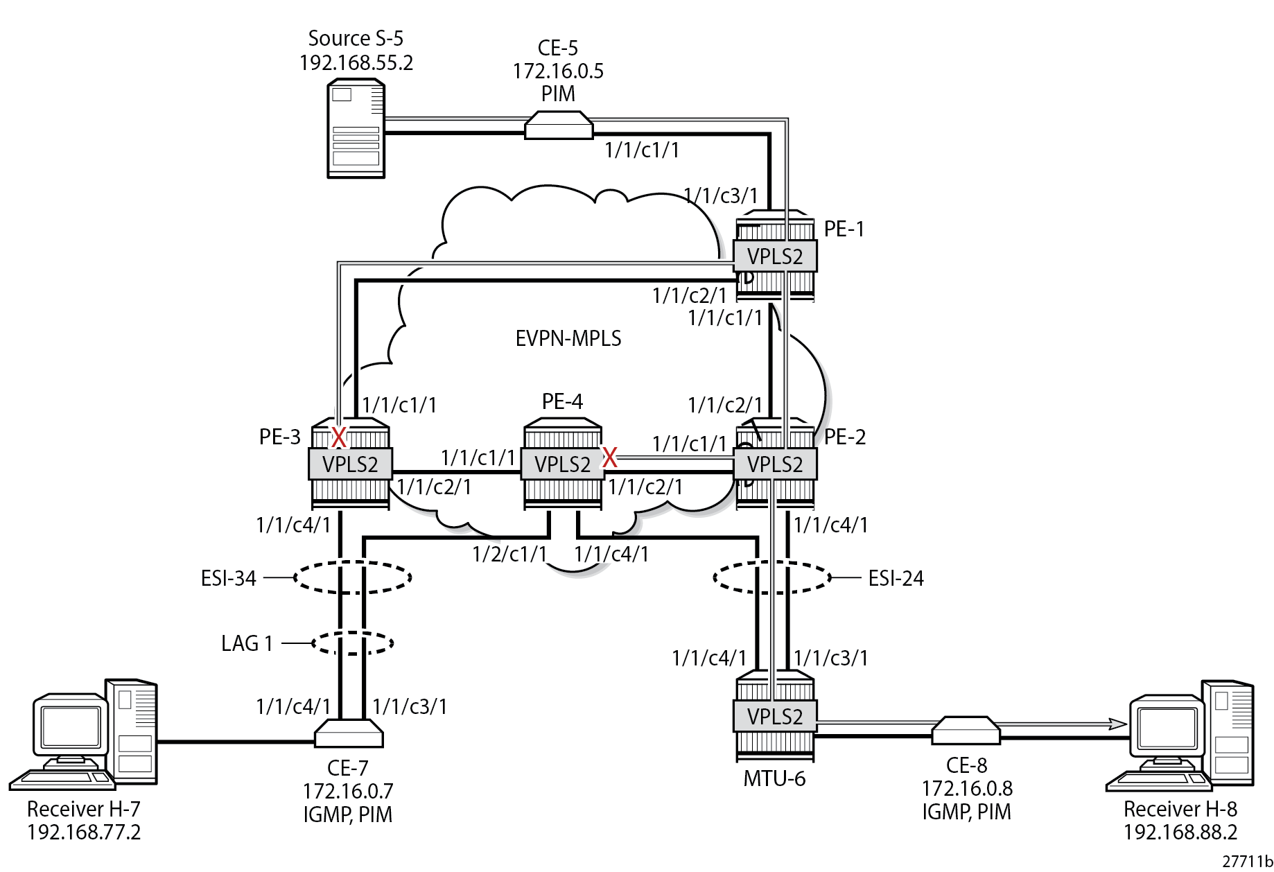
Example Topology with Multi-homing ESs shows the example topology with an all-active multi-homing virtual Ethernet Segment (ES) "ESI-34_2" between PE-3 and PE-4 using a LAG, and a single-active multi-homing ES "ESI-24" between PE-2 and PE-4 using SDPs.
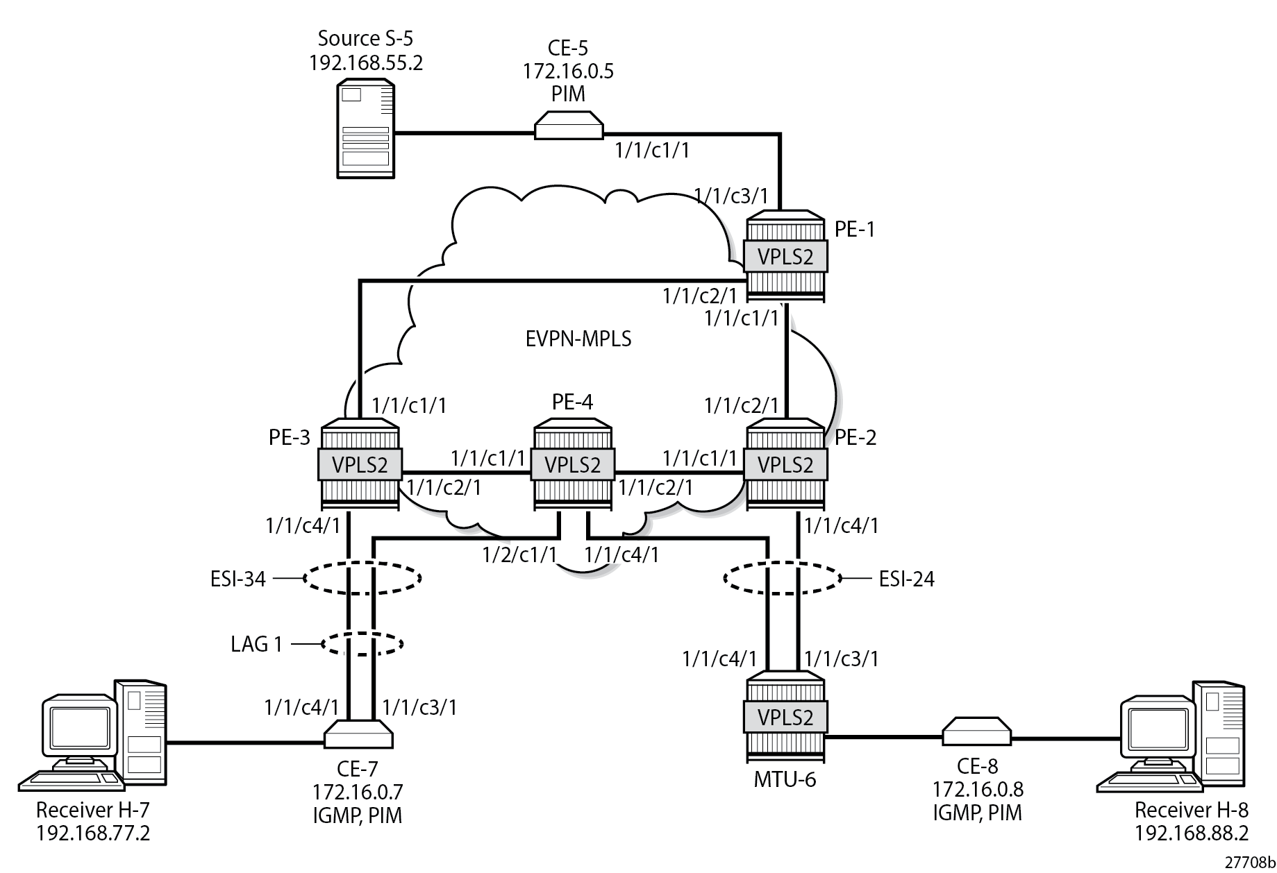
The configuration of VPLS 2 is similar to the configuration of VPLS 1 on all PEs. An identical P2MP mLDP provider tunnel is established on the PEs for VPLS 2: PE-1 is the root node, PE-2 is a leaf node and a transit node, PE-3 is a leaf node, and PE-4 is also a leaf node.
On PE-2, PE-3, and PE-4, one or more ESs are configured. The service configuration on PE-2 is as follows. An SDP is configured toward MTU-6 that is associated with a single-active multi-homing ES "ESI-24". Spoke-SDP 26:2 is associated with VPLS 2.
On PE-2:
configure {
    service {
        sdp 26 {
            admin-state enable
            delivery-type mpls
            ldp true
            far-end {
                ip-address 192.0.2.6
            }
        }
        vpls "VPLS 2" {
            admin-state enable
            service-id 2
            customer "1"
            bgp 1 { }
            bgp-evpn {
                evi 2
                mpls 1 {
                    admin-state enable
                    ingress-replication-bum-label true
                    auto-bind-tunnel {
                        resolution any
                    }
                }
            }
            spoke-sdp 26:2 { }
            provider-tunnel {
                inclusive {
                    admin-state enable
                    owner bgp-evpn-mpls
                    mldp
                }
            }
        }
        system {
            bgp {
                evpn {
                    ethernet-segment "ESI-24" {
                        admin-state enable
                        esi 0x01000000002400000001
                        multi-homing-mode single-active
                        df-election {
                            es-activation-timer 3
                            service-carving-mode manual
                            manual {
                                preference {
                                    mode non-revertive
                                    value 10000
                                }
                            }
                        }
                        association {
                            sdp 26 { }
                        }
                    }
                }
            }
        }
    }
}
The same ES is configured on PE-4, together with another ES-an all-active multi-homing virtual ES that applies to VPLS 2 only (q-tag-range 2); see chapter Virtual Ethernet Segments. The preference for the DF election is configured manually to a value of 5000 (which is lower than the preference 10000 on PE-3); see chapter Preference-based and Non-revertive EVPN DF Election. VPLS 2 has a SAP and a spoke-SDP configured. The service configuration on PE-4 is as follows:
On PE-4:
configure exclusive
    service {
        sdp 46 {
            admin-state enable
            delivery-type mpls
            ldp true
            far-end {
                ip-address 192.0.2.6
            }
        }
        vpls "VPLS 2" {
            admin-state enable
            service-id 2
            customer "1"
            bgp 1 { }
            bgp-evpn {
                evi 2
                mpls 1 {
                    admin-state enable
                    ingress-replication-bum-label true
                    auto-bind-tunnel {
                        resolution any
                    }
                }
            }
            spoke-sdp 46:2 { }
            sap lag-1:2 { }
            provider-tunnel {
                inclusive {
                    admin-state enable
                    owner bgp-evpn-mpls
                    mldp
                }
            }
        }
        system {
            bgp {
                evpn {
                    ethernet-segment "ESI-24" {
                        admin-state enable
                        esi 0x01000000002400000001
                        multi-homing-mode single-active
                        df-election {
                            es-activation-timer 3
                            service-carving-mode manual
                            manual {
                                preference {
                                    mode non-revertive
                                    value 5000
                                }
                            }
                        }
                        association {
                            sdp 46 { }
                        }
                    }
                    ethernet-segment "ESI-34_2" {
                        admin-state enable
                        type virtual
                        esi 0x01000000003402000001
                        multi-homing-mode all-active
                        df-election {
                            es-activation-timer 3
                            service-carving-mode manual
                            manual {
                                preference {
                                    mode non-revertive
                                    value 5000
                                }
                            }
                        }
                        association {
                            lag "lag-1" {
                                virtual-ranges {
                                    dot1q {
                                        q-tag 2 {
                                            end 2
                                        }
                                    }
                                }
                            }
                        }
                    }
                }
            }
        }
    }
}
The service configuration on PE-3 includes the same all-active multi-homing virtual ES with preference 10000, as follows:
On PE-3:
configure {
    service {
        vpls "VPLS 2" {
            admin-state enable
            service-id 2
            customer "1"
            bgp 1 { }
            bgp-evpn {
                evi 2
                mpls 1 {
                    admin-state enable
                    ingress-replication-bum-label true
                    auto-bind-tunnel {
                        resolution any
                    }
                }
            }
            sap lag-1:2 { }
            provider-tunnel {
                inclusive {
                    admin-state enable
                    owner bgp-evpn-mpls
                    mldp
                }
            }
        }
        system {
            bgp {
                evpn {
                    ethernet-segment "ESI-34_2" {
                        admin-state enable
                        type virtual
                        esi 0x01000000003402000001
                        multi-homing-mode all-active
                        df-election {
                            es-activation-timer 3
                            service-carving-mode manual
                            manual {
                                preference {
                                    mode non-revertive
                                    value 10000
                                }
                            }
                        }
                        association {
                            lag "lag-1" {
                                virtual-ranges {
                                    dot1q {
                                        q-tag 2 {
                                            end 2
                                        }
                                    }
                                }
                            }
                        }
                    }
                }
            }
        }
    }
}
The following is the service configuration on MTU-6:
On MTU-6:
configure {
    service {
        sdp 62 {
            admin-state enable
            delivery-type mpls
            ldp true
            far-end {
                ip-address 192.0.2.2
            }
        }
        sdp 64 {
            admin-state enable
            delivery-type mpls
            ldp true
            far-end {
                ip-address 192.0.2.4
            }
        }
        vpls "VPLS 2" {
            admin-state enable
            service-id 2
            customer "1"
            endpoint "x" { }
            spoke-sdp 62:2 {
                endpoint {
                    name "x"
                }
                stp {
                    admin-state disable
                }
            }
            spoke-sdp 64:2 {
                endpoint {
                    name "x"
                }
                stp {
                    admin-state disable
                }
            }
            sap 1/2/c1/1:2 { }
        }
    }
}
For VPLS 2, PE-2 is the DF in ES "ESI-24", as follows:
[/]
A:admin@PE-2# show service id 2 ethernet-segment
No sap entries

===============================================================================
SDP Ethernet-Segment Information
===============================================================================
SDP                   Eth-Seg                          Status
-------------------------------------------------------------------------------
26:2                  ESI-24                           DF
===============================================================================
No vxlan instance entries
PE-3 is the DF in ES "ESI-34_2", as follows:
[/]
A:admin@PE-3# show service id 2 ethernet-segment

===============================================================================
SAP Ethernet-Segment Information
===============================================================================
SAP                   Eth-Seg                          Status
-------------------------------------------------------------------------------
lag-1:2               ESI-34_2                         DF
===============================================================================
No sdp entries
No vxlan instance entries
PE-4 is NDF for both ESI-24 and ESI-34_2, as follows:
[/]
A:admin@PE-4# show service id 2 ethernet-segment

===============================================================================
SAP Ethernet-Segment Information
===============================================================================
SAP                   Eth-Seg                          Status
-------------------------------------------------------------------------------
lag-1:2               ESI-34_2                         NDF
===============================================================================

===============================================================================
SDP Ethernet-Segment Information
===============================================================================
SDP                   Eth-Seg                          Status
-------------------------------------------------------------------------------
46:2                  ESI-24                           NDF
===============================================================================
No vxlan instance entries
When H-8 sends an IGMP report to join multicast group 232.1.1.1 from source 192.168.55.2, CE-5 forwards the multicast stream after receiving the corresponding PIM join message. PE-1 forwards the multicast traffic on the P2MP mLDP tree to PE-2, PE-3, and PE-4. The DF PE-2 forwards the traffic to MTU-6, and DF PE-3 forwards it to CE-7, even though a PIM join for this group has not been received from CE-7. PE-4 is NDF, so it does not forward the traffic to MTU-6 or CE-7. MTU-6 forwards the traffic to CE-8, which sends it to H-8. CE-7 drops the multicast traffic because no attached receiver has joined the multicast group. EVPN-MPLS with Multi-homing – Receiver H-8 Joined shows how this multicast is forwarded when PIM snooping is disabled.
The static IGMP multicast is removed to emulate an IGMPv3 report from receiver H-8 to exclude multicast group 232.1.1.1 from source 192.168.55.2, as follows:
On CE-8:
configure {
    router "Base" {
        igmp {
            interface "int-CE-8-H-8" {
                static {
                    delete group 232.1.1.1
                }
            }
        }
    }
}
Multi-homed EVPN-MPLS VPLS with PIM Snooping
PIM snooping is enabled in VPLS 2 on all PEs, including PE-1, which is not part of an ES-with the following command:
configure {
    service {
        vpls "VPLS 2" {
            pim-snooping { }
        }
    }
}
All PEs have three PIM snooping neighbors: CE-5, CE-7, and CE-8. The list of PIM snooping neighbors on PE-1 is as follows:
[/]
A:admin@PE-1# show service id 2 pim-snooping neighbor

===============================================================================
PIM Snooping Neighbors ipv4
===============================================================================
Port Id                 Nbr DR Prty     Up Time       Expiry Time     Hold Time
  Nbr Address
-------------------------------------------------------------------------------
SAP:1/1/c3/1:2          1               0d 00:01:12   0d 00:01:33     105
  172.16.0.5
EVPN-MPLS               1               0d 00:01:14   0d 00:01:31     105
  172.16.0.7
EVPN-MPLS               1               0d 00:01:07   0d 00:01:38     105
  172.16.0.8
-------------------------------------------------------------------------------
Neighbors : 3
===============================================================================
On PE-2, the same PIM snooping neighbors are listed: CE-5, CE-7, and CE-8, as follows:
[/]
A:admin@PE-2# show service id 2 pim-snooping neighbor

===============================================================================
PIM Snooping Neighbors ipv4
===============================================================================
Port Id                 Nbr DR Prty     Up Time       Expiry Time     Hold Time
  Nbr Address
-------------------------------------------------------------------------------
SPOKE_SDP:26:2          1               0d 00:01:09   0d 00:01:35     105
  172.16.0.8
EVPN-MPLS               1               0d 00:01:15   0d 00:01:30     105
  172.16.0.5
EVPN-MPLS               1               0d 00:01:17   0d 00:01:27     105
  172.16.0.7
-------------------------------------------------------------------------------
Neighbors : 3
===============================================================================
PE-3 and PE-4 also have these three CEs as PIM snooping neighbors.
All-active MH EVPN-MPLS VPLS with PIM Snooping
On CE-7, the following static IGMP membership is configured on interface int-CE-7-H-7:
On CE-7:
configure {
    router "Base" {
        igmp {
            interface "int-CE-7-H-7" {
                ssm-translate {
                    group-range start 232.0.0.0 end 232.255.255.255 {
                        source 192.168.55.2 { }
                    }
                }
                static {
                    group 232.1.1.1 {
                        source 192.168.55.2 { }
                    }
                }
            }
        }
    }
}
When H-7 joins the multicast group 232.1.1.1 via source 192.168.55.2, the PIM join messages are snooped by the PEs and the MFIB is built. The MFIB on PE-1 contains one entry for group address 232.1.1.1 and source address 192.168.55.2, with four port IDs: the local SAP to CE-5 and the EVPN-MPLS destinations, as follows:
[/]
A:admin@PE-1# show service id 2 mfib

===============================================================================
Multicast FIB, Service 2
===============================================================================
Source Address  Group Address         Port Id                      Svc Id   Fwd
                                                                            Blk
-------------------------------------------------------------------------------
192.168.55.2    232.1.1.1             sap:1/1/c3/1:2               Local    Fwd
                                      mpls:192.0.2.2:524280        Local    Fwd
                                      mpls:192.0.2.3:524280        Local    Fwd
                                      mpls:192.0.2.4:524280        Local    Fwd
-------------------------------------------------------------------------------
Number of entries: 1
===============================================================================
The MFIB on PE-2 is empty because no locally attached node has sent a PIM join for any multicast group:
[/]
A:admin@PE-2# show service id 2 mfib

===============================================================================
Multicast FIB, Service 2
===============================================================================
Source Address  Group Address         Port Id                      Svc Id   Fwd
                                                                            Blk
-------------------------------------------------------------------------------
-------------------------------------------------------------------------------
Number of entries: 0
===============================================================================
The MFIB on PE-3 contains an entry for the (S,G) with the local SAP lag-1:2 and the EVPN-MPLS destination, as follows:
[/]
A:admin@PE-3# show service id 2 mfib

===============================================================================
Multicast FIB, Service 2
===============================================================================
Source Address  Group Address         Port Id                      Svc Id   Fwd
                                                                            Blk
-------------------------------------------------------------------------------
192.168.55.2    232.1.1.1             sap:lag-1:2                  Local    Fwd
                                      mpls:192.0.2.1:524280        Local    Fwd
                                      mpls:192.0.2.2:524280        Local    Fwd
                                      mpls:192.0.2.4:524280        Local    Fwd
-------------------------------------------------------------------------------
Number of entries: 1
===============================================================================
Data-driven PIM state synchronization between PE-3 and PE-4 in the ESI-34_2 results in the following MFIB entry on PE-4:
[/]
A:admin@PE-4# show service id 2 mfib

===============================================================================
Multicast FIB, Service 2
===============================================================================
Source Address  Group Address         Port Id                      Svc Id   Fwd
                                                                            Blk
-------------------------------------------------------------------------------
192.168.55.2    232.1.1.1             sap:lag-1:2                  Local    Fwd
                                      mpls:192.0.2.1:524280        Local    Fwd
                                      mpls:192.0.2.2:524280        Local    Fwd
                                      mpls:192.0.2.3:524280        Local    Fwd
-------------------------------------------------------------------------------
Number of entries: 1
===============================================================================
When debugging is enabled on the PEs as follows, the synchronization between peers in ES "ESI-34_2" is logged:
debug {
    service {
        vpls "VPLS 2" {
            pim-snooping {
                events {
                    port {
                        evpn-mpls
                    }
                    jp { }
                }
                packet {
                    packet-types {
                        jp true
                    }
                }
            }
        }
    }
}
For example, PE-4 sends the following PIM message to its remote peer PE-3 in ESI-34_2:
82 2023/08/10 23:13:20.784 CEST MINOR: DEBUG #2001 Base PIM[vpls 2 ]
"PIM[vpls 2 ]: pimVplsFwdJPToEvpn
Forwarding to remote peer on bgp-evpn ethernet-segment ESI-34_2"
PE-3 receives the following PIM message from its remote peer PE-4 in ESI-34_2:
74 2023/08/10 23:13:20.786 CEST MINOR: DEBUG #2001 Base PIM[vpls 2 ]
"PIM[vpls 2 ]: pimProcessPdu
Received from remote peer on bgp-evpn ethernet-segment ESI-34_2, will be applied on lag-1:2
"
On PE-1, the PIM snooping group (192.168.55.2, 232.1.1.1) has incoming interface SAP 1/1/c3/1:2 toward CE-5 and the EVPN-MPLS interface as outgoing interface, as follows:
[/]
A:admin@PE-1# show service id 2 pim-snooping group detail

===============================================================================
PIM Snooping Source Group ipv4
===============================================================================
Group Address      : 232.1.1.1
Source Address     : 192.168.55.2
Up Time            : 0d 00:01:10

Up JP State        : Joined             Up JP Expiry       : 0d 00:00:50
Up JP Rpt          : Not Joined StarG   Up JP Rpt Override : 0d 00:00:00

RPF Neighbor       : 172.16.0.5
Incoming Intf      : SAP:1/1/c3/1:2
Outgoing Intf List : EVPN-MPLS, SAP:1/1/c3/1:2

Forwarded Packets  : 57863              Forwarded Octets   : 86794500
-------------------------------------------------------------------------------
Groups : 1
===============================================================================
On PE-2, no PIM join messages are received and no groups are listed, as follows:
[/]
A:admin@PE-2# show service id 2 pim-snooping group detail

===============================================================================
PIM Snooping Source Group ipv4
===============================================================================
No Matching Entries
===============================================================================
On PE-3, the same PIM snooping group has the EVPN-MPLS as incoming interface and the SAP lag-1:2 as outgoing interface. The split-horizon mechanism ensures that the multicast traffic that enters through the EVPN-MPLS interface is not forwarded on the EVPN-MPLS interface, which is regarded as a single interface.
[/]
A:admin@PE-3# show service id 2 pim-snooping group detail

===============================================================================
PIM Snooping Source Group ipv4
===============================================================================
Group Address      : 232.1.1.1
Source Address     : 192.168.55.2
Up Time            : 0d 00:01:13

Up JP State        : Joined             Up JP Expiry       : 0d 00:00:02
Up JP Rpt          : Not Joined StarG   Up JP Rpt Override : 0d 00:00:00

RPF Neighbor       : 172.16.0.5
Incoming Intf      : EVPN-MPLS
Outgoing Intf List : EVPN-MPLS, SAP:lag-1:2

Forwarded Packets  : 60286              Forwarded Octets   : 90187856
-------------------------------------------------------------------------------
Groups : 1
===============================================================================
On PE-4, the same PIM snooping information is available, because of the data-driven PIM state synchronization between PE-3 and PE-4 in ESI-34_2, as follows:
[/]
A:admin@PE-4# show service id 2 pim-snooping group detail
===============================================================================
PIM Snooping Source Group ipv4
===============================================================================
Group Address : 232.1.1.1
Source Address : 192.168.55.2
Up Time : 0d 00:01:14
Up JP State : Joined Up JP Expiry : 0d 00:00:59
Up JP Rpt : Not Joined StarG Up JP Rpt Override : 0d 00:00:00
RPF Neighbor : 172.16.0.5
Incoming Intf : EVPN-MPLS
Outgoing Intf List : EVPN-MPLS, SAP:lag-1:2
Forwarded Packets : 61554 Forwarded Octets : 92084784
-------------------------------------------------------------------------------
Groups : 1
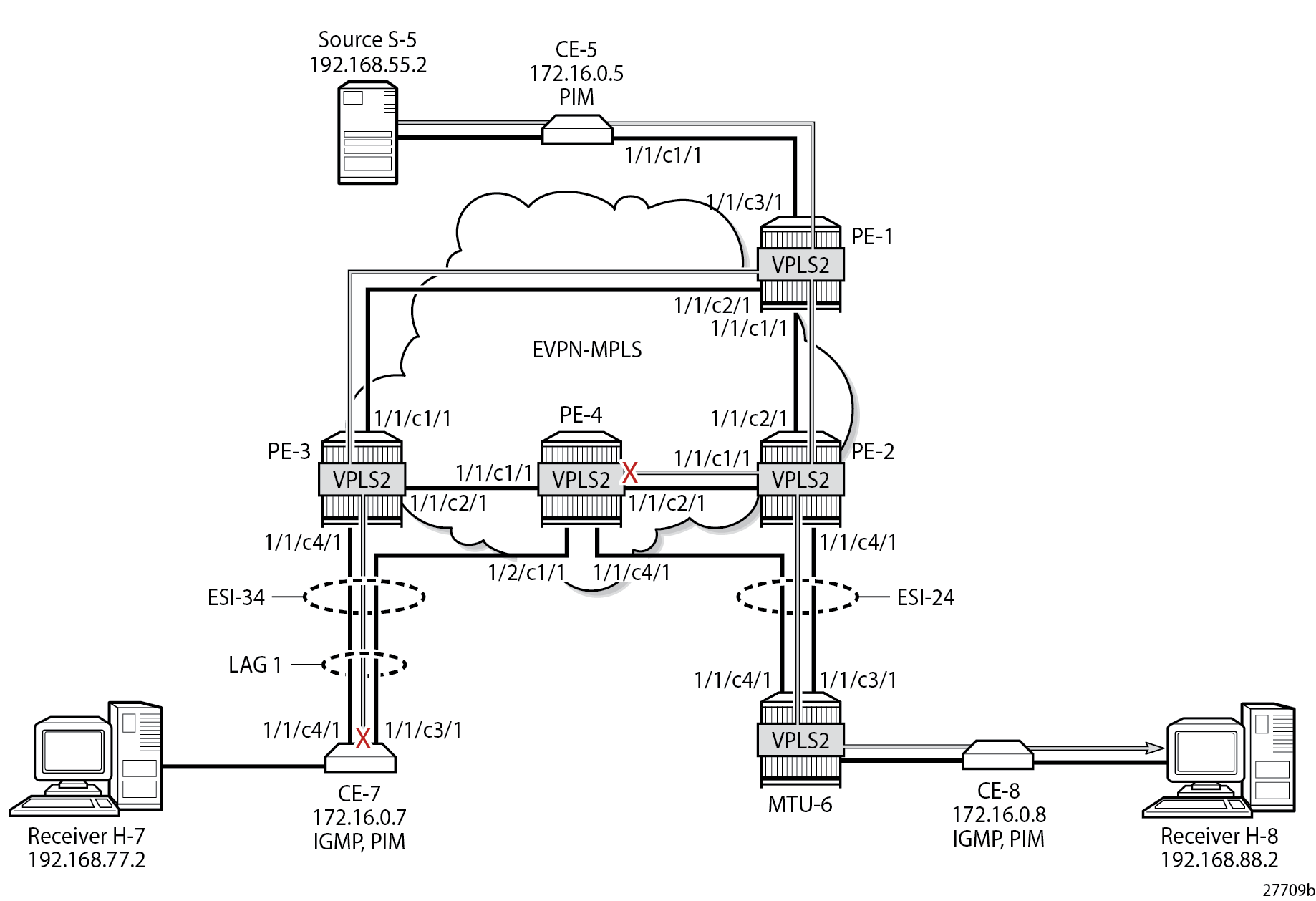
===============================================================================EVPN-MPLS with All-active Multi-homing and PIM Snooping Enabled – Receiver H-7 Joined shows how the multicast traffic is forwarded when H-7 joins the multicast group and PIM snooping is enabled. DF PE-3 forwards the traffic toward CE-7. The multicast stream also reaches PE-2 and PE-4, where it is dropped.
H-7 leaves the multicast group and H-8 joins it instead.
Single-active MH EVPN-MPLS VPLS with PIM Snooping
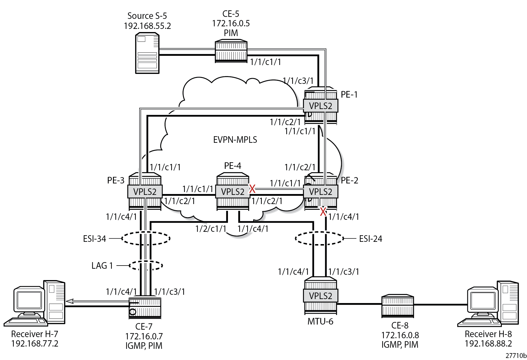
When H-8 joins the multicast group and PIM snooping is enabled, only DF PE-2 forwards traffic from the EVPN-MPLS toward a receiver. PE-3 does not forward traffic to CE-7 because no PIM join message was received from CE-7. EVPN-MPLS with Single-active Multi-homing and PIM Snooping Enabled – Receiver H-8 Joined shows how the multicast traffic is forwarded when H-8 joins the multicast group and PIM snooping is enabled.
On PE-1, the MFIB looks the same as in the preceding case, as follows:
[/]
A:admin@PE-1# show service id 2 mfib

===============================================================================
Multicast FIB, Service 2
===============================================================================
Source Address  Group Address         Port Id                      Svc Id   Fwd
                                                                            Blk
-------------------------------------------------------------------------------
192.168.55.2    232.1.1.1             sap:1/1/c3/1:2               Local    Fwd
                                      mpls:192.0.2.2:524280        Local    Fwd
                                      mpls:192.0.2.3:524280        Local    Fwd
                                      mpls:192.0.2.4:524280        Local    Fwd
-------------------------------------------------------------------------------
Number of entries: 1
===============================================================================
On PE-2, the MFIB contains an entry for source address 192.168.55.2 and group address 232.1.1.1 with spoke-SDP 26:2 and the EVPN-MPLS destinations to the other PEs, as follows:
[/]
A:admin@PE-2# show service id 2 mfib

===============================================================================
Multicast FIB, Service 2
===============================================================================
Source Address  Group Address         Port Id                      Svc Id   Fwd
                                                                            Blk
-------------------------------------------------------------------------------
192.168.55.2    232.1.1.1             sdp:26:2                     Local    Fwd
                                      mpls:192.0.2.1:524280        Local    Fwd
                                      mpls:192.0.2.3:524280        Local    Fwd
                                      mpls:192.0.2.4:524280        Local    Fwd
-------------------------------------------------------------------------------
Number of entries: 1
===============================================================================
The MFIB on PE-3 is empty, because multicast traffic toward H-8 is not sent via PE-3, as follows:
[/]
A:admin@PE-3# show service id 2 mfib

===============================================================================
Multicast FIB, Service 2
===============================================================================
Source Address  Group Address         Port Id                      Svc Id   Fwd
                                                                            Blk
-------------------------------------------------------------------------------
-------------------------------------------------------------------------------
Number of entries: 0
===============================================================================
The data-driven PIM state synchronization ensures that DF PE-2 sends updates to NDF PE-4. With debugging enabled, the following debug message is displayed at PE-2:
205 2023/08/10 23:15:21.053 CEST MINOR: DEBUG #2001 Base PIM[vpls 2 ]
"PIM[vpls 2 ]: pimVplsFwdJPToEvpn
Forwarding to remote peer on bgp-evpn ethernet-segment ESI-24"
The following debug message is displayed at PE-4:
122 2023/08/10 23:15:21.053 CEST MINOR: DEBUG #2001 Base PIM[vpls 2 ]
"PIM[vpls 2 ]: pimProcessPdu
Received from remote peer on bgp-evpn ethernet-segment ESI-24, will be applied on 46:2
"
As a result, the MFIB on PE-4 is not empty, as follows:
[/]
A:admin@PE-4# show service id 2 mfib

===============================================================================
Multicast FIB, Service 2
===============================================================================
Source Address  Group Address         Port Id                      Svc Id   Fwd
                                                                            Blk
-------------------------------------------------------------------------------
192.168.55.2    232.1.1.1             sdp:46:2                     Local    Fwd
                                      mpls:192.0.2.1:524280        Local    Fwd
                                      mpls:192.0.2.2:524280        Local    Fwd
                                      mpls:192.0.2.3:524280        Local    Fwd
-------------------------------------------------------------------------------
Number of entries: 1
===============================================================================
On PE-1, the PIM snooping group (192.168.55.2, 232.1.1.1) has incoming interface SAP 1/1/c3/1:2 toward CE-5 and the EVPN-MPLS interface as outgoing interface, as follows:
[/]
A:admin@PE-1# show service id 2 pim-snooping group detail

===============================================================================
PIM Snooping Source Group ipv4
===============================================================================
Group Address      : 232.1.1.1
Source Address     : 192.168.55.2
Up Time            : 0d 00:01:09

Up JP State        : Joined             Up JP Expiry       : 0d 00:00:50
Up JP Rpt          : Not Joined StarG   Up JP Rpt Override : 0d 00:00:00

RPF Neighbor       : 172.16.0.5
Incoming Intf      : SAP:1/1/c3/1:2
Outgoing Intf List : EVPN-MPLS, SAP:1/1/c3/1:2

Forwarded Packets  : 57409              Forwarded Octets   : 86113500
-------------------------------------------------------------------------------
Groups : 1
===============================================================================
On PE-2, the same PIM snooping group has the EVPN-MPLS as incoming interface and the spoke-SDP 26:2 as outgoing interface. Again, the split-horizon mechanism ensures that the multicast traffic that enters through the EVPN-MPLS interface is not forwarded on the EVPN-MPLS interface, which is regarded as a single interface.
[/]
A:admin@PE-2# show service id 2 pim-snooping group detail

===============================================================================
PIM Snooping Source Group ipv4
===============================================================================
Group Address      : 232.1.1.1
Source Address     : 192.168.55.2
Up Time            : 0d 00:01:12

Up JP State        : Joined             Up JP Expiry       : 0d 00:01:14
Up JP Rpt          : Not Joined StarG   Up JP Rpt Override : 0d 00:00:00

RPF Neighbor       : 172.16.0.5
Incoming Intf      : EVPN-MPLS
Outgoing Intf List : EVPN-MPLS, SPOKE_SDP:26:2

Forwarded Packets  : 59634              Forwarded Octets   : 89212464
-------------------------------------------------------------------------------
Groups : 1
===============================================================================
On PE-3, no PIM join messages are received and no groups are listed, as follows:
[/]
A:admin@PE-3# show service id 2 pim-snooping group detail

===============================================================================
PIM Snooping Source Group ipv4
===============================================================================
No Matching Entries
===============================================================================
On PE-4, the same PIM snooping information is available, because of the data-driven PIM state synchronization between PE-2 and PE-4 in ESI-24, as follows. The incoming interface is the EVPN-MPLS interface and the outgoing interface is spoke-SDP 46:2.
[/]
A:admin@PE-4# show service id 2 pim-snooping group detail

===============================================================================
PIM Snooping Source Group ipv4
===============================================================================
Group Address      : 232.1.1.1
Source Address     : 192.168.55.2
Up Time            : 0d 00:01:15

Up JP State        : Joined             Up JP Expiry       : 0d 00:00:52
Up JP Rpt          : Not Joined StarG   Up JP Rpt Override : 0d 00:00:00

RPF Neighbor       : 172.16.0.5
Incoming Intf      : EVPN-MPLS
Outgoing Intf List : EVPN-MPLS, SPOKE_SDP:46:2

Forwarded Packets  : 62461              Forwarded Octets   : 93441656
-------------------------------------------------------------------------------
Groups : 1
===============================================================================
PIM state synchronization is data-driven, so the PIM states are not stored in a database. Therefore, the ESs must be configured as non-revertive to avoid reverting back to the preferred PE while this PE is unaware of the PIM states.
PIM Snooping with Multi-chassis Synchronization
Data-driven PIM state synchronization is supported in SR OS Release 15.0.R4, and later. The ES must be configured as non-revertive, so that after a failover, the new DF remains the DF even when the original DF is operational again. When data-driven PIM state synchronization cannot be used, for example, when the service carving is configured in auto mode, or when the SR OS Release is an earlier release of 15.0, Multi-chassis synchronization (MCS) can be configured for a faster failover. MCS of the PIM snooping state on SAPs and spoke-SDPs is supported between an active and a standby PE and the PIM states are stored in a synchronization database. This can be configured in case of single-active multi-homing (MH), for example on PE-2 for peer PE-4, with PIM snooping on spoke-SDPs, as follows:
On PE-2:
configure {
    redundancy {
        multi-chassis {
            peer 192.0.2.4 {
                admin-state enable
                sync {
                    admin-state enable
                    pim-snooping {
                        spoke-sdps true
                    }
                    tags {
                        sdp 26 {
                            range start 2 end 2 {
                                sync-tag "syncSA"
                            }
                        }
                    }
                }
            }
        }
    }
}
On PE-4, MCS is configured for peer PE-2, as follows:
On PE-4:
configure {
    redundancy {
        multi-chassis {
            peer 192.0.2.2 {
                admin-state enable
                sync {
                    admin-state enable
                    pim-snooping {
                        spoke-sdps true
                    }
                    tags {
                        sdp 46 {
                            range start 2 end 2 {
                                sync-tag "syncSA"
                            }
                        }
                    }
                }
            }
        }
    }
}
When H-8 joins the multicast group, the following entries are in the MCS synchronization database of the PEs. The MCS sync-database on PE-2 shows the PIM snooping entries on the spoke-SDP 26:2 of the single-active MH ESI-24, as follows:
[/]
A:admin@PE-2# tools dump redundancy multi-chassis sync-database detail

If no entries are present for an application, no detail will be displayed.

FLAGS LEGEND: ld - local delete; da - delete alarm; pd - pending global delete;
              oal - omcr alarmed; ost - omcr standby

Peer Ip 192.0.2.4


Application pim-snooping-sdp
Sdp-id             Client Key
 SyncTag                          DLen  Flags            timeStamp
  deleteReason code and description                   #ShRec
-------------------------------------------------------------------------------
26:2               Adj 172.16.0.8
 syncSA                           72    -- -- -- --- --- 08/10/2023 23:24:27
  0x0                                                 0
26:2               IfSG SG 192.168.55.2 232.1.1.1
 syncSA                           69    -- -- -- --- --- 08/10/2023 23:24:21
  0x0                                                 0

The following totals are for:
 peer ip ALL, port/lag/sdp ALL, sync-tag ALL, application ALL
Valid Entries:                   2
Locally Deleted Entries:         0
Locally Deleted Alarmed Entries: 0
Pending Global Delete Entries:   0
Omcr Alarmed Entries:            0
Omcr Standby Entries:            0
Associated Shared Records (ALL): 0
Associated Shared Records (LD):  0
The MCS sync-database on PE-4 is similar, with SDP ID 46:2 instead of 26:2.
On PE-4, the MFIB is populated as follows:
[/]
A:admin@PE-4# show service id 2 mfib

===============================================================================
Multicast FIB, Service 2
===============================================================================
Source Address  Group Address         Port Id                      Svc Id   Fwd
                                                                            Blk
-------------------------------------------------------------------------------
192.168.55.2    232.1.1.1             sdp:46:2                     Local    Fwd
                                      mpls:192.0.2.1:524280        Local    Fwd
                                      mpls:192.0.2.2:524280        Local    Fwd
                                      mpls:192.0.2.3:524280        Local    Fwd
-------------------------------------------------------------------------------
Number of entries: 1
===============================================================================
The PIM snooping group information on PE-4 shows the EVPN-MPLS as incoming interface and the spoke-SDP as outgoing interface, as follows. The split-horizon mechanism does not allow forwarding traffic from the EVPN-MPLS back to the EVPN-MPLS.
[/]
A:admin@PE-4# show service id 2 pim-snooping group detail

===============================================================================
PIM Snooping Source Group ipv4
===============================================================================
Group Address      : 232.1.1.1
Source Address     : 192.168.55.2
Up Time            : 0d 00:01:15

Up JP State        : Joined             Up JP Expiry       : 0d 00:00:52
Up JP Rpt          : Not Joined StarG   Up JP Rpt Override : 0d 00:00:00

RPF Neighbor       : 172.16.0.5
Incoming Intf      : EVPN-MPLS
Outgoing Intf List : EVPN-MPLS, SPOKE_SDP:46:2

Forwarded Packets  : 62461              Forwarded Octets   : 93441656
-------------------------------------------------------------------------------
Groups : 1
===============================================================================
Failover
EVPN-MPLS with Multi-homing and PIM Snooping - Receivers H-7 and H-8 Joined shows the multicast traffic flow in the case where both receivers H-7 and H-8 joined multicast group 232.1.1.1 from source 192.168.55.2 and no failures have occurred. For SR OS Release 15.0.R4, and later, MCS need not be configured for faster failover in single-active MH when the ES is non-revertive.
NDF PE-4 has an MFIB table with the required information for a fast failover, as follows:
[/]
A:admin@PE-4# show service id 2 mfib

===============================================================================
Multicast FIB, Service 2
===============================================================================
Source Address  Group Address         Port Id                      Svc Id   Fwd
                                                                            Blk
-------------------------------------------------------------------------------
192.168.55.2    232.1.1.1             sap:lag-1:2                  Local    Fwd
                                      sdp:46:2                     Local    Fwd
                                      mpls:192.0.2.1:524280        Local    Fwd
                                      mpls:192.0.2.2:524280        Local    Fwd
                                      mpls:192.0.2.3:524280        Local    Fwd
-------------------------------------------------------------------------------
Number of entries: 1
===============================================================================
In SR OS Release 15.0.R4, and later, data-driven PIM state synchronization ensures that NDF PE-4 has the following PIM snooping information for group 232.1.1.1.
[/]
A:admin@PE-4# show service id 2 pim-snooping group detail

===============================================================================
PIM Snooping Source Group ipv4
===============================================================================
Group Address      : 232.1.1.1
Source Address     : 192.168.55.2
Up Time            : 0d 00:03:12

Up JP State        : Joined             Up JP Expiry       : 0d 00:00:59
Up JP Rpt          : Not Joined StarG   Up JP Rpt Override : 0d 00:00:00

RPF Neighbor       : 172.16.0.5
Incoming Intf      : EVPN-MPLS
Outgoing Intf List : EVPN-MPLS, SAP:lag-1:2, SPOKE_SDP:46:2

Forwarded Packets  : 158148             Forwarded Octets   : 236589408
-------------------------------------------------------------------------------
Groups : 1
===============================================================================
The following failures are introduced to force a failover from PE-2 to PE-4 and from PE-3 to PE-4. On MTU-6, SDP 62 is disabled, as follows:
configure {
    service {
        sdp 62 {
            admin-state disable
        }
    }
}
On CE-7, port 1/1/c4/1 toward PE-3 is disabled, as follows:
configure {
    port 1/1/c4/1 {
        admin-state disable
    }
}
Log 99 on PE-3 shows that the DF state in ESI-34_2 changed to false:
172 2023/08/10 23:18:51.662 CEST MINOR: SVCMGR #2094 Base
"Ethernet Segment:ESI-34_2, EVI:2, Designated Forwarding state changed to:false"
PE-4 becomes the DF for both ESs, as follows:
[/]
A:admin@PE-4# show service id 2 ethernet-segment

===============================================================================
SAP Ethernet-Segment Information
===============================================================================
SAP                   Eth-Seg                          Status
-------------------------------------------------------------------------------
lag-1:2               ESI-34_2                         DF
===============================================================================

===============================================================================
SDP Ethernet-Segment Information
===============================================================================
SDP                   Eth-Seg                          Status
-------------------------------------------------------------------------------
46:2                  ESI-24                           DF
===============================================================================
No vxlan instance entries
EVPN-MPLS with Multi-homing and PIM Snooping - Multicast Flow after Failover shows the traffic flow after failover to new DF PE-4.
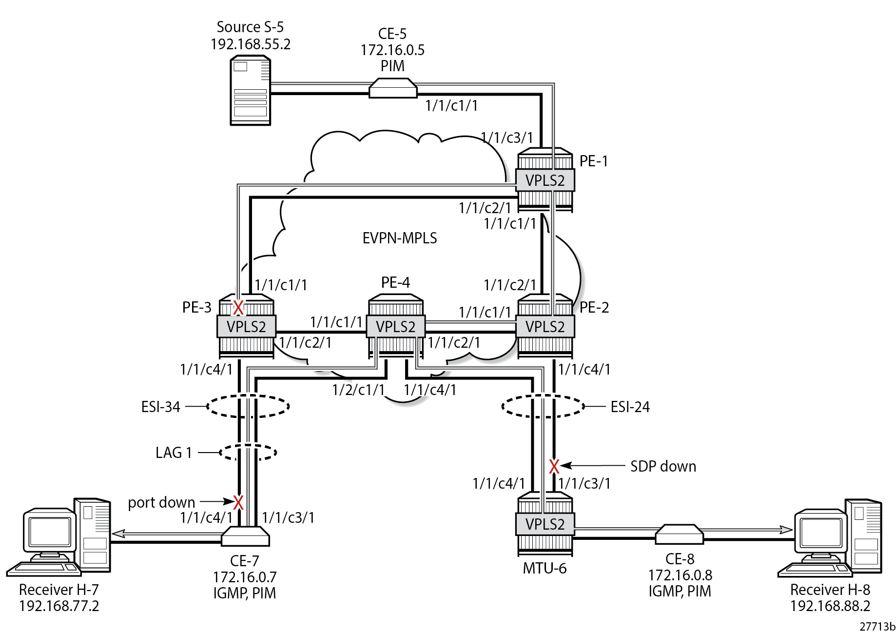
PE-1 receives the multicast on port 1/1/c3/1 and forwards it on port 1/1/c1/1 to PE-2, and on port 1/1/c2/1 to PE-3, as follows:
[/]
A:admin@PE-1# show port 1/1/c1/1 statistics

===============================================================================
Port Statistics on Slot 1
===============================================================================
Port                        Ingress Packets                  Ingress Octets
Id                           Egress Packets                   Egress Octets
-------------------------------------------------------------------------------
1/1/c1/1                                 34                            3412
                                      26284                        39855201
===============================================================================

[/]
A:admin@PE-1# show port 1/1/c2/1 statistics

===============================================================================
Port Statistics on Slot 1
===============================================================================
Port                        Ingress Packets                  Ingress Octets
Id                           Egress Packets                   Egress Octets
-------------------------------------------------------------------------------
1/1/c2/1                                 28                            2946
                                      26281                        39854977
===============================================================================

[/]
A:admin@PE-1# show port 1/1/c3/1 statistics

===============================================================================
Port Statistics on Slot 1
===============================================================================
Port                        Ingress Packets                  Ingress Octets
Id                           Egress Packets                   Egress Octets
-------------------------------------------------------------------------------
1/1/c3/1                              26255                        39486092
                                          2                             152
===============================================================================
PE-2 receives the multicast stream from PE-1 on port 1/1/c2/1 and forwards it to port 1/1/c1/1 to PE-4; it does not forward to port 1/1/c4/1 because SDP 26 is down, as follows:
[/]
A:admin@PE-2# show port 1/1/c1/1 statistics

===============================================================================
Port Statistics on Slot 1
===============================================================================
Port                        Ingress Packets                  Ingress Octets
Id                           Egress Packets                   Egress Octets
-------------------------------------------------------------------------------
1/1/c1/1                                 36                            3664
                                      26428                        40075241
===============================================================================

[/]
A:admin@PE-2# show port 1/1/c2/1 statistics

===============================================================================
Port Statistics on Slot 1
===============================================================================
Port                        Ingress Packets                  Ingress Octets
Id                           Egress Packets                   Egress Octets
-------------------------------------------------------------------------------
1/1/c2/1                              26430                        40075436
                                         34                            3412
===============================================================================

[/]
A:admin@PE-2# show port 1/1/c3/1 statistics

[/]
A:admin@PE-2# show port 1/1/c4/1 statistics

===============================================================================
Port Statistics on Slot 1
===============================================================================
Port                        Ingress Packets                  Ingress Octets
Id                           Egress Packets                   Egress Octets
-------------------------------------------------------------------------------
1/1/c4/1                                 25                            2686
                                         27                            2921
===============================================================================
PE-4 receives the multicast traffic on port 1/1/c2/1 and forwards it on port 1/1/c4/1 toward MTU-6, and on port 1/2/c1/1 to CE-7, as follows:
[/]
A:admin@PE-4# show port 1/1/c1/1 statistics

===============================================================================
Port Statistics on Slot 1
===============================================================================
Port                        Ingress Packets                  Ingress Octets
Id                           Egress Packets                   Egress Octets
-------------------------------------------------------------------------------
1/1/c1/1                                 28                            2948
                                         29                            3056
===============================================================================

[/]
A:admin@PE-4# show port 1/1/c2/1 statistics

===============================================================================
Port Statistics on Slot 1
===============================================================================
Port                        Ingress Packets                  Ingress Octets
Id                           Egress Packets                   Egress Octets
-------------------------------------------------------------------------------
1/1/c2/1                              26274                        39841553
                                         30                            3088
===============================================================================

[/]
A:admin@PE-4# show port 1/1/c4/1 statistics

===============================================================================
Port Statistics on Slot 1
===============================================================================
Port                        Ingress Packets                  Ingress Octets
Id                           Egress Packets                   Egress Octets
-------------------------------------------------------------------------------
1/1/c4/1                                 26                            2814
                                      26270                        40051218
===============================================================================

[/]
A:admin@PE-4# show port 1/2/c1/1 statistics

===============================================================================
Port Statistics on Slot 1
===============================================================================
Port                        Ingress Packets                  Ingress Octets
Id                           Egress Packets                   Egress Octets
-------------------------------------------------------------------------------
1/2/c1/1                                 33                            4172
                                      26278                        39475224
===============================================================================
MTU-6 forwards the traffic to CE-8, which forwards it to H-8. CE-7 forwards the traffic to H-7. PE-3 drops the multicast traffic because LAG-1 is down because of the failure that was introduced at CE-7 (port disabled).
Conclusion
PIM snooping in EVPN-MPLS services results in a more efficient use of network resources because multicast traffic no longer needs to be flooded. PIM snooping can be used in EVPN-MPLS services with all-active and single-active multi-homing with data-driven PIM state synchronization. Alternatively, MCS synchronization of the PIM snooping state on SAPs and spoke-SDPs is supported with single-active MH.