P2MP mLDP Tunnels for BUM Traffic in EVPN-MPLS Services
This chapter provides information about P2MP mLDP Tunnels for BUM Traffic in EVPN-MPLS Services.
Topics in this chapter include:
Applicability
This chapter was initially written for SR OS Release 14.0.R4, but the CLI in the current edition is based on SR OS Release 23.3.R3.
Point-to-Multipoint (P2MP) multicast Label Distribution Protocol (mLDP) tunnels for Broadcast, Unknown unicast, and Multicast (BUM) traffic in Ethernet Virtual Private Network Multiprotocol Label Switching (EVPN-MPLS) networks are supported in SR OS Release 14.0.R1, and later. Internet Group Management Protocol (IGMP) snooping support for EVPN-MPLS services is supported in SR OS Release 14.0.R4, and later.
Overview
Service providers are moving their existing VPN services to EVPN. Providers using P2MP LSPs for VPLS services expect the same capabilities in EVPN. Before SR OS Release 14.0.R1, only Ingress Replication (IR) was supported. This works well for broadcast and unknown unicast traffic, but it is inefficient for multicast. Ingress replication does not use a multicast mechanism. Instead, the parent node makes n individual copies and unicasts each copy through an MPLS or IP tunnel to each child node.
BUM traffic is sent from a root node to a number of leaf nodes, but leaf nodes are also allowed to send BUM traffic to root nodes. If most BUM traffic is flowing from a few root nodes to leaf nodes, it would be inefficient to promote all leaf nodes to root-and-leaf nodes because of the amount of P2MP tunnels that would need to be set up. Another solution is to use a combination of P2MP mLDP and ingress replication (IR) tunnels in the service. The root nodes send BUM traffic using P2MP tunnels while the leaf nodes use IR tunnels to send BUM traffic to the root nodes. This avoids the need to set up a P2MP tree from each leaf, while it still allows leaf nodes to send BUM traffic to the root nodes.
P2MP mLDP tree with root node PE-1 and leaf nodes PE-5, PE-6, and PE-7 shows a multicast mLDP tree with root node PE-1 and leaf nodes PE-5, PE-6, and PE-7.
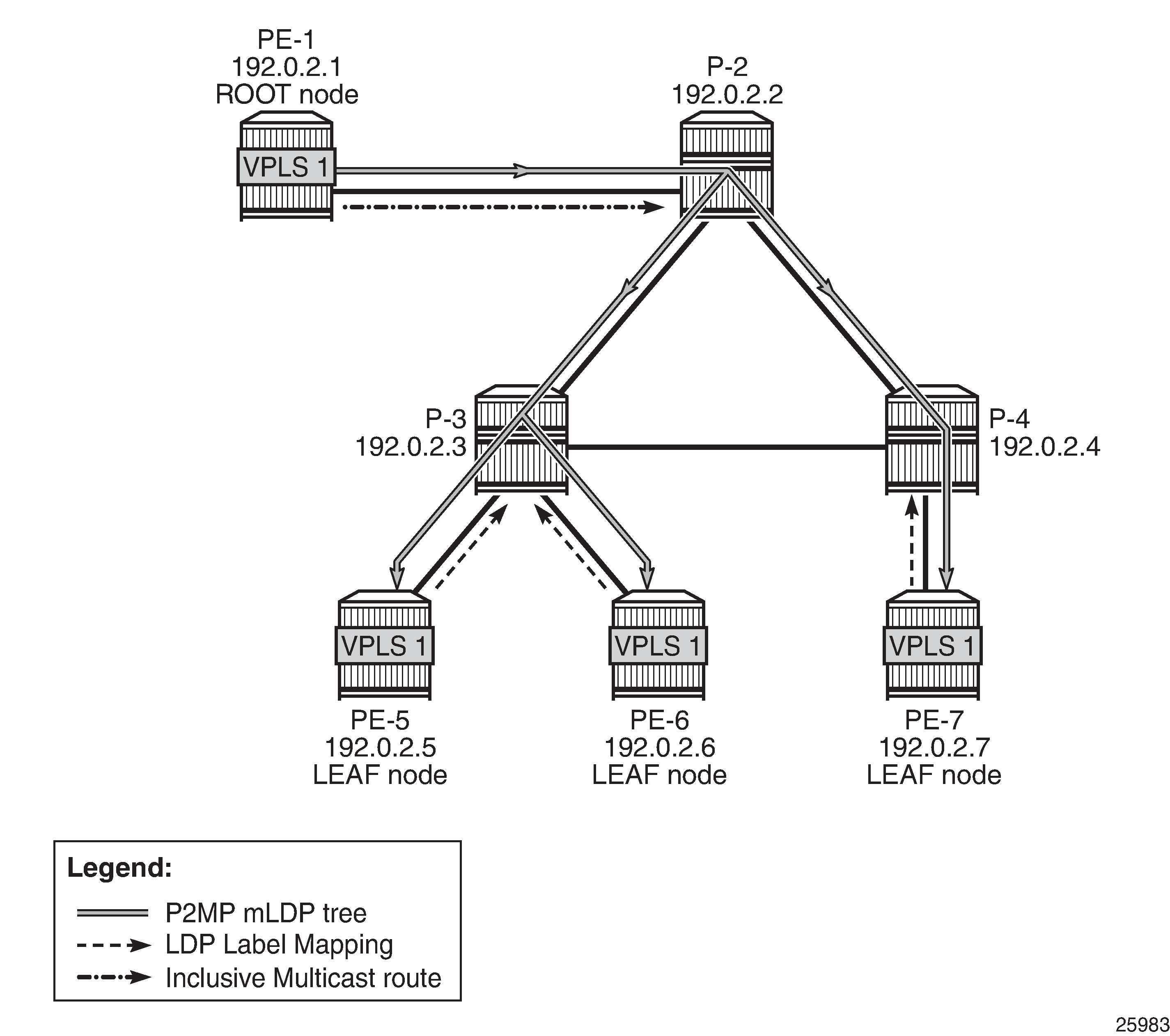
The Inclusive Multicast Ethernet Tag (IMET) route (EVPN route type 3) sent by root node PE-1 contains the required information to set up an mLDP tree, such as the root node IP address and an opaque value. As described in chapter "Multicast Label Distribution Protocol" in the MPLS volume of the 7450 ESS, 7750 SR, and 7950 XRS Advanced Configuration Guide - Part I, the mLDP tree is set up from the leaf nodes toward the root.
The LDP label mapping message contains the root node address, an opaque value, and an MPLS label. The leaf nodes send an LDP label mapping message to their upstream next hop toward the root node of the tree. Each transit node that has received such LDP label mapping message generates a new LDP label mapping message to its upstream next hop toward the root. This is repeated until the root node receives an LDP label mapping message and the multicast tree is completed.
P2MP mLDP tree with root node PE-1 and leaf nodes PE-5, PE-6, and PE-7 shows a P2MP mLDP tree rooted in PE-1, which is optimal for multicast traffic. However, no P2MP mLDP tree needs to be rooted in PE-5, PE-6, and PE-7 for the reverse direction. These three PEs can use IR to send traffic to the root (and to the other leaf nodes if needed).
EVPN route type 3 is used for setting up the flooding tree for a specified VPLS service. EVPN route type 3 includes the Provider Multicast Service Interface (PMSI) Tunnel Attribute (PMSI Tunnel Attribute = PTA), which can have different formats depending on the tunnel type; see BGP-EVPN route type 3 with PTA.
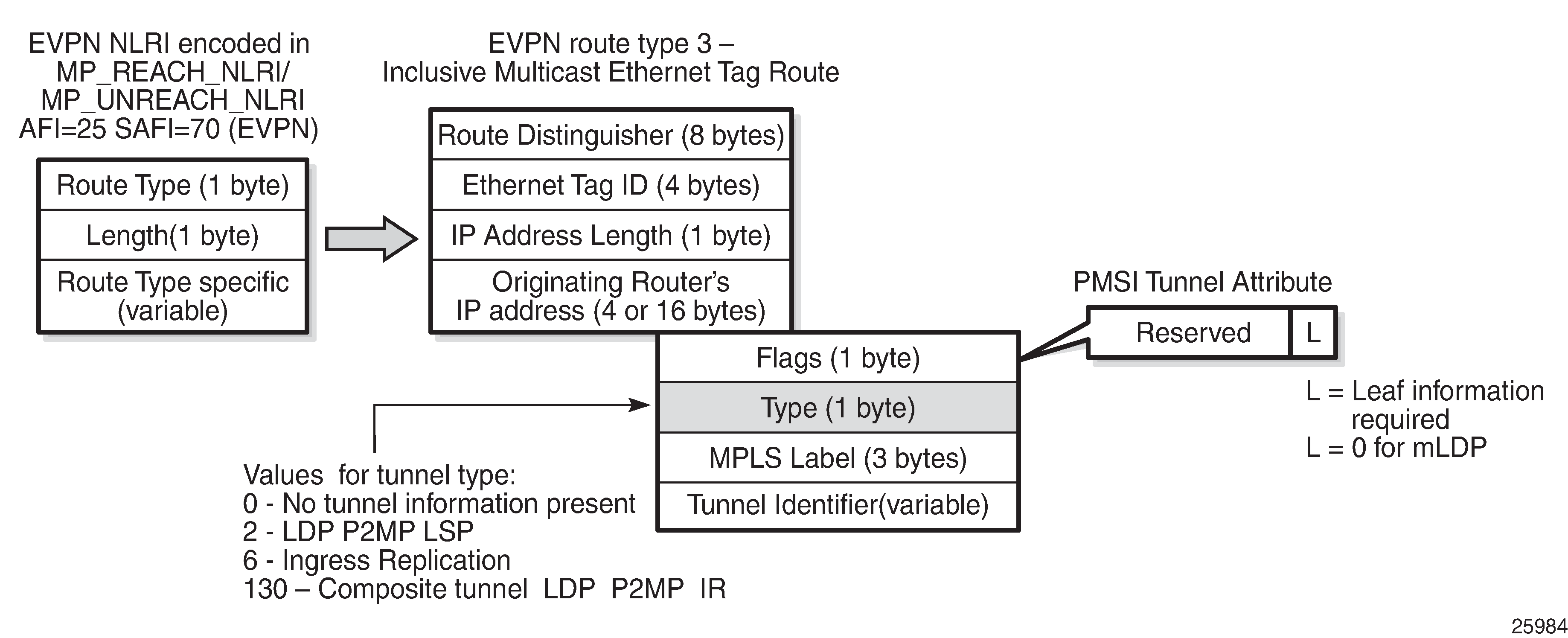
The following route values are used for EVPN-MPLS services:
The route distinguisher (RD) is taken from the RD of the VPLS service, which can be configured in the BGP context or auto-derived from the BGP-EVPN EVPN Instance (EVI) value. In this case, the RD is auto-derived from the EVI, resulting in a value of 192.0.2.1:1 for VPLS 1 on PE-1.
The Ethernet tag ID equals 0.
The IP address length equals 32.
The originating router's IP address carries the IPv4 system address.
The PTA can have different formats depending on the tunnel type enabled in the service. The SR OS EVPN-MPLS implementation supports the following tunnel types (SR OS supports different tunnel types for EVPN-VXLAN):
Tunnel type 2 - P2MP mLDP
The route is referred to as an Inclusive Multicast Ethernet Tag Point-to-Multipoint (IMET-P2MP).
Flags: leaf not required.
The MPLS label is zero.
The tunnel identifier includes the root node address and an opaque number. This is the tunnel identifier that the leaf nodes use to join to the mLDP P2MP tree.
Tunnel type 6 - Ingress Replication (IR)
The route is referred to as an Inclusive Multicast Ethernet Tag Ingress Replication (IMET-IR).
Flags: leaf not required.
The MPLS label is a non-zero, downstream allocated label. This MPLS label is allocated to the service and is the same for unicast MAC/IP routes for the same service, unless ingress-replication-bum-label is configured in the service.
The tunnel identifier is the tunnel endpoint and is equal to the originating IP address.
Tunnel type 130 - Composite tunnel: Type: C-bit (composite) + type 2 (mLDP)
The route is referred to as an IMET-P2MP-IR.
Flags: leaf not required.
MPLS label 1 equals zero.
MPLS label 2 is a non-zero, downstream allocated label (as any other IR label). The leaf nodes use the label to set up an EVPN-MPLS binding to the root and add it to the default multicast list.
The mLDP tunnel identifier is the root node address and an opaque number. This is the tunnel identifier that the leaf nodes use to join the mLDP P2MP tree.
PTA for composite tunnel IMET-P2MP-IR shows the PTA for tunnel type 130.

The composite bit C is set, indicating that the PTA identifies two tunnels: the transmit tunnel is a P2MP mLDP tunnel and the receive tunnel is an IR tunnel.
IMET-P2MP-IR routes
The composite tunnel type is an optimized solution that combines mLDP and IR within the same EVPN service so that each root node sends BUM traffic using the P2MP tunnel whereas each leaf-only node sends BUM traffic to the root node using IR.
PEs configured with root-and-leaf can send all BUM traffic over P2MP mLDP tunnels while they receive BUM traffic either over P2MP mLDP tunnels (from other root-and-leaf nodes) or over ingress-replication tunnels (from leaf-only nodes).
PEs configured without root-and-leaf (default setting) can use IR to send BUM traffic to root nodes and other leaf-only nodes, while receiving BUM traffic over either P2MP mLDP tunnels (from root nodes) or ingress-replication tunnels (from leaf-only nodes).
The root PEs signal an IMET-P2MP-IR route, indicating that they intend to transmit BUM traffic using an mLDP P2MP tunnel, while they can receive traffic over an IR EVPN-MPLS binding. Composite tunnels reduce the number of P2MP mLDP tunnels that the PE/P routers in the EVI need to handle, because no full mesh of P2MP tunnels among all the PEs in the EVI is required. This is important (in terms of scaling) in services where there are just a pair of root nodes sending BUM in P2MP tunnels and hundreds of leaf nodes that only need to send BUM traffic to the root nodes using IR tunnels.
Configuration
Initial configuration
The PE and P nodes have the following initial configuration:
The ports between the routers are configured as network ports and have router interfaces configured.
IS-IS is enabled on all the router interfaces.
LDP is enabled on all the router interfaces.
BGP is enabled on all PEs with route reflector (RR) P-2. The BGP configuration on RR P-2 is as follows:
# On P-2:
configure {
    router "Base" {
        autonomous-system 64500
        bgp {
            vpn-apply-import true
            vpn-apply-export true
            peer-ip-tracking true
            rapid-withdrawal true
            split-horizon true
            ebgp-default-reject-policy {
                import false
                export false
            }
            rapid-update {
                evpn true
            }
            group "internal" {
                peer-as 64500
                family {
                    evpn true
                }
                cluster {
                    cluster-id 1.1.1.1
                }
            }
            neighbor "192.0.2.1" {
                group "internal"
            }
            neighbor "192.0.2.5" {
                group "internal"
            }
            neighbor "192.0.2.6" {
                group "internal"
            }
            neighbor "192.0.2.7" {
                group "internal"
            }
        }
    }
Configure EVPN P2MP mLDP in VPLS Service
On the root node PE-1, VPLS 1 is configured as follows:
# On PE-1:
configure {
    service {
        vpls "VPLS 1" {
            admin-state enable
            service-id 1
            customer "1"
            bgp 1 {
            }
            bgp-evpn {
                evi 1
                mpls 1 {
                    admin-state enable
                    auto-bind-tunnel {
                        resolution any
                    }
                }
            }
            provider-tunnel {
                inclusive {
                    admin-state enable
                    owner bgp-evpn-mpls
                    root-and-leaf true
                    mldp
                }
            }
            sap 1/2/c3/1 {    # sap for ingress traffic from STC
            }
        }
    }
The configuration options in the bgp-evpn context of the VPLS are as follows:
configure {
    service {
        vpls "VPLS 1" {
            bgp-evpn ?
*[ex:/configure service vpls "VPLS 1"]
A:admin@PE-1#             bgp-evpn ?

 bgp-evpn

 accept-ivpls-evpn-    - Accept and process non-zero ethernet-tag MAC routes
  flush
 apply-groups          - Apply a configuration group at this level
 apply-groups-exclude  - Exclude a configuration group at this level
 evi                   - EVPN ID
 ignore-mtu-mismatch   - Ignore MTU mismatch
 incl-mcast-orig-ip    - Originating IP address
 isid-route-target     + Enter the isid-route-target context
 mac-duplication       + Enter the mac-duplication context
 mpls                  + Enter the mpls list instance
 routes                + Enter the routes context
 segment-routing-v6    + Enter the segment-routing-v6 list instance
 vxlan                 + Enter the vxlan list instance
By default, the advertisement of the inclusive multicast route with IR is enabled (ingress-repl-inc-mcast-advertisement). However, if it is disabled, the router does not send the IMET-IR or IMET-P2MP-IR routes, regardless of the service being enabled for BGP EVPN-MPLS or BGP EVPN-VXLAN.
For information about the other parameters in the bgp-evpn context of the VPLS, see chapters EVPN for VXLAN Tunnels (Layer 2) and EVPN for MPLS Tunnels.
The configuration options in the provider-tunnel inclusive context are as follows:
configure {
    service {
        vpls "VPLS 1" {
            provider-tunnel {
                inclusive ?
*[ex:/configure service vpls "VPLS 1" provider-tunnel]
A:admin@PE-1#                 inclusive ?

 inclusive

 admin-state           - Administrative state of P2MP LSP as the I-PMSI
 data-delay-interval   - I-PMSI data delay timer
 owner                 - Configure provider-tunnel owner
 root-and-leaf         - Configure whether the provider tunnel acts as a leaf or both a root and leaf

 Choice: ipmsi
 mldp                 :- Enable/Disable MLDP
 rsvp                 :+ Enter the rsvp context
The data-delay-interval is configured in seconds in the range from 3 to 180 seconds. A node configured with root-and-leaf sends all BUM packets (data plane and control plane: ARP, CCMs, and so on) to its provider tunnel after the delay-data-interval has expired. This timer keeps the provider tunnel operationally down until its expiration, and, during that time, the router can use the EVPN-MPLS destinations typically used for IR.
mLDP is enabled by adding the keyword mldp and enabling the provider tunnel (admin-state enable).
The owner must be bgp-evpn-mpls if MPLS is enabled in the EVPN.
configure {
    service {
        vpls "VPLS 1" {
            provider-tunnel {
                inclusive {
                    owner ?
*[ex:/configure service vpls "VPLS 1" provider-tunnel inclusive]
A:admin@PE-1#                     owner ?

 owner <keyword>
 <keyword> - (bgp-ad|bgp-vpls|bgp-evpn-mpls)
Only one of the three possible owner protocols supports the provider tunnel in the service and needs to be set before the provider tunnel can be enabled. By default, no owner is configured. The following error is raised when a user wants to enable the provider tunnel without an owner:
*[ex:/configure service vpls "VPLS 1" provider-tunnel inclusive]
MINOR: SVCMGR #12: configure service vpls "VPLS 1" provider-tunnel inclusive admin-state
 - Inconsistent Value error
 - no owner configured for the provider tunnel
After the provider tunnel has an owner and is enabled, the owner can only be changed when the provider tunnel is disabled.
*[ex:/configure service vpls "VPLS 1" provider-tunnel inclusive]
MINOR: MGMT_CORE #4001: configure service vpls "VPLS 1" provider-tunnel inclusive owner
 - the enabled provider-tunnel cannot have owner set to bgp-vpls when evpn-mpls is enabled
 - configure service vpls "VPLS 1" bgp-evpn mpls 1 admin-state
After the owner is set, the corresponding protocol is checked to see if it is enabled in the service configuration.
*[ex:/configure service vpls "VPLS 1" provider-tunnel inclusive]
MINOR: SVCMGR #12: configure service vpls "VPLS 1" provider-tunnel inclusive admin-state
 - Inconsistent Value error
 - bgp-vpls must be configured when the provider tunnel with owner bgp-vpls is enabled
 - configure service vpls "VPLS 1"
If ingress-repl-inc-mcast-advertisement is enabled and the PE is configured with root-and-leaf, the router sends an IMET-P2MP-IR route; if the PE is configured without root-and-leaf (default), the router sends an IMET-IR route. However, if ingress-repl-inc-mcast-advertisement is disabled and the PE is configured with root-and-leaf, the router only sends IMET-P2MP routes. Leaf-only nodes do not send any IMET routes at all in case no IR multicast advertisement is allowed.
Root-and-leaf nodes only send BUM traffic to the P2MP tunnel as long as it is active. If the P2MP tunnel goes operationally down, it starts sending BUM traffic to IR tunnels (EVPN-MPLS destinations shown in the show service id 1 evpn-mpls command).
If a provider tunnel is configured on a node, the router can join P2MP trees as a leaf, by generating an LDP label mapping message including the corresponding P2MP mLDP FEC. If no provider tunnel is configured, the node does not join P2MP mLDP trees, and can only use IR for BUM.
If one node is configured as root, all other nodes must be configured with provider tunnels; otherwise, they do not receive BUM traffic sent on P2MP tunnels. The configuration of leaf-only node PE-5 is as follows, the main difference with the configuration for the root being the absence of root-and-leaf (default setting):
# On PE-5:
configure {
    service {
        vpls "VPLS 1" {
            admin-state enable
            service-id 1
            customer "1"
            bgp 1 {
            }
            bgp-evpn {
                evi 1
                mpls 1 {
                    admin-state enable
                    auto-bind-tunnel {
                        resolution any
                    }
                }
            }
            provider-tunnel {
                inclusive {
                    admin-state enable
                    owner bgp-evpn-mpls
                    mldp
                }
            }
            sap 1/2/c1/1:1 {    # sap for egress traffic to VPLS 1
            }
        }
    }
As described, the tunnel types for BUM traffic are controlled by ingress-repl-inc-mcast-advertisement and the provider-tunnel context (root-and-leaf). The IMET route sending behavior is summarized in IMET routes and Tunnel Types advertised based on the configuration .
|
IMET route set |
Root + Leaf PE |
Leaf-only |
No provider-tunnel |
|---|---|---|---|
|
IR-mcast advertisement |
Composite P2MP + IR |
IR |
IR |
|
No IR-mcast advertisement |
P2MP |
- |
- |
Information about the provider tunnel can be retrieved as follows:
[/]
A:admin@PE-1# show service id 1 provider-tunnel

===============================================================================
Service Provider Tunnel Information
===============================================================================
Type               : inclusive          Root and Leaf      : enabled
Admin State        : enabled            Data Delay Intvl   : 15 secs
PMSI Type          : ldp                LSP Template       :
Remain Delay Intvl : 0 secs             LSP Name used      : 8193
PMSI Owner         : bgpEvpnMpls
Oper State         : up                 Root Bind Id       : 32767
-------------------------------------------------------------------------------
Type               : selective          Wildcard SPMSI     : disabled
Admin State        : disabled           Data Delay Intvl   : 3 secs
PMSI Type          : none               Max P2MP SPMSI     : 10
PMSI Owner         : none
===============================================================================
The same IMET-P2MP route cannot be imported by two services at the same time. If two VPLS services (where a provider tunnel is enabled) have the same import route-target, only one service joins the mLDP tree (whichever comes first).
EVPN P2MP mLDP operation
After the root node and leaf nodes are configured as shown, the root node sends BGP EVPN composite IMET-P2MP-IR routes, as follows:
# On PE-1:
2 2023/07/03 22:26:27.189 CEST MINOR: DEBUG #2001 Base Peer 1: 192.0.2.2
"Peer 1: 192.0.2.2: UPDATE
Peer 1: 192.0.2.2 - Send BGP UPDATE:
    Withdrawn Length = 0
    Total Path Attr Length = 93
    Flag: 0x90 Type: 14 Len: 28 Multiprotocol Reachable NLRI:
        Address Family EVPN
        NextHop len 4 NextHop 192.0.2.1
        Type: EVPN-INCL-MCAST Len: 17 RD: 192.0.2.1:1, tag: 0, orig_addr len: 32, orig_addr: 192.0.2.1
    Flag: 0x40 Type: 1 Len: 1 Origin: 0
    Flag: 0x40 Type: 2 Len: 0 AS Path:
    Flag: 0x40 Type: 5 Len: 4 Local Preference: 100
    Flag: 0xc0 Type: 16 Len: 16 Extended Community:
        target:64500:1
        bgp-tunnel-encap:MPLS
    Flag: 0xc0 Type: 22 Len: 25 PMSI:
        Tunnel-type Composite LDP P2MP IR (130)
        Flags: (0x0)[Type: None BM: 0 U: 0 Leaf: not required]
        MPLS Label1 Ag  0
        MPLS Label2 IR 8388480
        Root-Node 192.0.2.1, LSP-ID 0x2001
"
The PTA for tunnel type 130 (composite tunnel) has two MPLS labels, of which MPLS label 1 equals zero. MPLS label 2 is used by the downstream nodes to set up the EVPN-MPLS destination to the root node and add it to the default multicast list. The actual MPLS label only uses the high-order 20 bits out of the 24 bits advertised in the MPLS label. Therefore, the value 8388480 needs to be divided by 16 to have the MPLS label: 8388480/16 = 524280. This is because the debug message is shown before the router can parse the label field and see whether it corresponds to an MPLS label (20 bits) or a VXLAN VNI (24 bits).
The tunnel identifier field contains the root node address 192.0.2.1 and the opaque value 0x2001, which corresponds to decimal value 8193. With this tunnel identifier, the leaf nodes can join the mLDP multicast tree toward the root node by sending LDP label mapping messages that contain the root node IP address and the opaque value.
When static P2MP mLDP tunnels and dynamic P2MP mLDP tunnels used by BGP-EVPN coexist on the same router,Nokia recommends that the static tunnels use a tunnel ID less than 8193. If a tunnel ID is statically configured with a value equal to or greater than 8193, BGP-EVPN may attempt to use the same tunnel ID for services with an enabled provider tunnel and fail to set up an mLDP tunnel.
The root node PE-1 receives IMET-IR routes from all leaf nodes, as shown for the BGP update sent by leaf node PE-5 (via RR P-2):
# On PE-1:
3 2023/07/03 22:28:45.189 CEST MINOR: DEBUG #2001 Base Peer 1: 192.0.2.2
"Peer 1: 192.0.2.2: UPDATE
Peer 1: 192.0.2.2 - Received BGP UPDATE:
    Withdrawn Length = 0
    Total Path Attr Length = 91
    Flag: 0x90 Type: 14 Len: 28 Multiprotocol Reachable NLRI:
        Address Family EVPN
        NextHop len 4 NextHop 192.0.2.5
        Type: EVPN-INCL-MCAST Len: 17 RD: 192.0.2.5:1, tag: 0, orig_addr len: 32, orig_addr: 192.0.2.5
    Flag: 0x40 Type: 1 Len: 1 Origin: 0
    Flag: 0x40 Type: 2 Len: 0 AS Path:
    Flag: 0x40 Type: 5 Len: 4 Local Preference: 100
    Flag: 0x80 Type: 9 Len: 4 Originator ID: 192.0.2.5
    Flag: 0x80 Type: 10 Len: 4 Cluster ID:
        1.1.1.1
    Flag: 0xc0 Type: 16 Len: 16 Extended Community:
        target:64500:1
        bgp-tunnel-encap:MPLS
    Flag: 0xc0 Type: 22 Len: 9 PMSI:
        Tunnel-type Ingress Replication (6)
        Flags: (0x0)[Type: None BM: 0 U: 0 Leaf: not required]
        MPLS Label 8388480
        Tunnel-Endpoint 192.0.2.5
"
The PTA tunnel type 6 for IR has only one MPLS label, which corresponds to the MPLS label 524280 allocated for the service. The tunnel identifier is the tunnel endpoint 192.0.2.5, which is the system address of the originating leaf node.
On leaf node PE-5, three BGP EVPN inclusive multicast routes have been learned and are used, as follows:
[/]
A:admin@PE-5# show router bgp routes evpn incl-mcast
===============================================================================
 BGP Router ID:192.0.2.5        AS:64500       Local AS:64500
===============================================================================
 Legend -
 Status codes  : u - used, s - suppressed, h - history, d - decayed, * - valid
                 l - leaked, x - stale, > - best, b - backup, p - purge
 Origin codes  : i - IGP, e - EGP, ? - incomplete

===============================================================================
BGP EVPN Inclusive-Mcast Routes
===============================================================================
Flag  Route Dist.         OrigAddr
      Tag                 NextHop
-------------------------------------------------------------------------------
u*>i  192.0.2.1:1         192.0.2.1
      0                   192.0.2.1

u*>i  192.0.2.6:1         192.0.2.6
      0                   192.0.2.6

u*>i  192.0.2.7:1         192.0.2.7
      0                   192.0.2.7

-------------------------------------------------------------------------------
Routes : 3
===============================================================================
The details of the BGP EVPN inclusive multicast route sent by root node PE-1 to leaf node PE-5 are as follows:
[/]
A:admin@PE-5# show router bgp routes evpn incl-mcast rd 192.0.2.1:1 detail
===============================================================================
 BGP Router ID:192.0.2.5        AS:64500       Local AS:64500
===============================================================================
 Legend -
 Status codes  : u - used, s - suppressed, h - history, d - decayed, * - valid
                 l - leaked, x - stale, > - best, b - backup, p - purge
 Origin codes  : i - IGP, e - EGP, ? - incomplete

===============================================================================
BGP EVPN Inclusive-Mcast Routes
===============================================================================
Original Attributes

Network        : n/a
Nexthop        : 192.0.2.1
Path Id        : None
From           : 192.0.2.2
Res. Nexthop   : 192.168.35.1
Local Pref.    : 100                    Interface Name : int-PE-5-P-3
Aggregator AS  : None                   Aggregator     : None
Atomic Aggr.   : Not Atomic             MED            : None
AIGP Metric    : None                   IGP Cost       : 30
Connector      : None
Community      : target:64500:1 bgp-tunnel-encap:MPLS
Cluster        : 1.1.1.1
Originator Id  : 192.0.2.1              Peer Router Id : 192.0.2.2
Flags          : Used Valid Best IGP
Route Source   : Internal
AS-Path        : No As-Path
EVPN type      : INCL-MCAST
Tag            : 0
Originator IP  : 192.0.2.1
Route Dist.    : 192.0.2.1:1
Route Tag      : 0
Neighbor-AS    : n/a
DB Orig Val    : N/A                    Final Orig Val : N/A
Source Class   : 0                      Dest Class     : 0
Add Paths Send : Default
Last Modified  : 00h01m30s
-------------------------------------------------------------------------------
PMSI Tunnel Attributes :
Tunnel-type    : Composite LDP P2MP IR
Flags          : Type: RNVE(0) BM: 0 U: 0 Leaf: not required
MPLS Label1 Ag : LABEL 0
MPLS Label2 IR : LABEL 524280
Root-Node      : 192.0.2.1              LSP-ID         : 8193
-------------------------------------------------------------------------------
---snip---
-------------------------------------------------------------------------------
Routes : 1
===============================================================================
The MPLS label is 524280, as described. The LSP ID equals 8193, which corresponds to the hexadecimal value 0x2001 in the preceding BGP update message sent by the root node PE-1.
To set up the mLDP tree, leaf node PE-5 has generated an LDP label mapping message to the next hop router toward the root, P-3. The label mapping message includes the root address 192.0.2.1, the opaque value 8193, and MPLS label 524279, as follows:
[/]
A:admin@PE-5# show router ldp bindings active p2mp ipv4

===============================================================================
LDP Bindings (IPv4 LSR ID 192.0.2.5)
             (IPv6 LSR ID ::)
===============================================================================
Label Status:
        U - Label In Use, N - Label Not In Use, W - Label Withdrawn
        WP - Label Withdraw Pending, BU - Alternate For Fast Re-Route
        e - Label ELC
FEC Flags:
        LF - Lower FEC, UF - Upper FEC, M - Community Mismatch,
        BA - ASBR Backup FEC
===============================================================================
LDP Generic IPv4 P2MP Bindings (Active)
===============================================================================
P2MP-Id                                     Interface
RootAddr                                    Op
IngLbl                                      EgrLbl
EgrNH                                       EgrIf/LspId
-------------------------------------------------------------------------------
8193                                        73728
192.0.2.1                                   Pop
524279                                        --
  --                                          --

-------------------------------------------------------------------------------
No. of Generic IPv4 P2MP Active Bindings: 1
---snip---
===============================================================================
P-3 has received two label mapping messages: one from PE-5 and one from PE-6. P-3 has sent one label mapping message to its upstream next hop P-2 with label 524279, as follows:
[/]
A:admin@P-3# show router ldp bindings active p2mp ipv4 opaque-type generic

===============================================================================
LDP Bindings (IPv4 LSR ID 192.0.2.3)
             (IPv6 LSR ID ::)
===============================================================================
Label Status:
        U - Label In Use, N - Label Not In Use, W - Label Withdrawn
        WP - Label Withdraw Pending, BU - Alternate For Fast Re-Route
        e - Label ELC
FEC Flags:
        LF - Lower FEC, UF - Upper FEC, M - Community Mismatch,
        BA - ASBR Backup FEC
===============================================================================
LDP Generic IPv4 P2MP Bindings (Active)
===============================================================================
P2MP-Id                                     Interface
RootAddr                                    Op
IngLbl                                      EgrLbl
EgrNH                                       EgrIf/LspId
-------------------------------------------------------------------------------
8193                                        Unknw
192.0.2.1                                   Swap
524280                                      524279
192.168.35.2                                1/1/c3/1

8193                                        Unknw
192.0.2.1                                   Swap
524280                                      524279
192.168.36.2                                1/1/c4/1

-------------------------------------------------------------------------------
No. of Generic IPv4 P2MP Active Bindings: 2
===============================================================================
P-2 has received two label mapping messages: one from P-3 and one from P-4. P-2 has sent a label mapping message toward the root node PE-1 with label 524280, as follows:
[/]
A:admin@P-2# show router ldp bindings active p2mp ipv4 opaque-type generic

===============================================================================
LDP Bindings (IPv4 LSR ID 192.0.2.2)
             (IPv6 LSR ID ::)
===============================================================================
Label Status:
        U - Label In Use, N - Label Not In Use, W - Label Withdrawn
        WP - Label Withdraw Pending, BU - Alternate For Fast Re-Route
        e - Label ELC
FEC Flags:
        LF - Lower FEC, UF - Upper FEC, M - Community Mismatch,
        BA - ASBR Backup FEC
===============================================================================
LDP Generic IPv4 P2MP Bindings (Active)
===============================================================================
P2MP-Id                                     Interface
RootAddr                                    Op
IngLbl                                      EgrLbl
EgrNH                                       EgrIf/LspId
-------------------------------------------------------------------------------
8193                                        Unknw
192.0.2.1                                   Swap
524280                                      524280
192.168.23.2                                1/1/c2/1

8193                                        Unknw
192.0.2.1                                   Swap
524280                                      524280
192.168.24.2                                1/1/c1/1

-------------------------------------------------------------------------------
No. of Generic IPv4 P2MP Active Bindings: 2
===============================================================================
When the LDP label reaches the root node PE-1, the mLDP tree is complete and it can be used for BUM traffic.
The following tools command shows the provider tunnels for VPLS 1 on root node and leaf nodes. On root node PE-1, there is one originating inclusive provider tunnel and there are no terminating inclusive provider tunnels, as follows:
[/]
A:admin@PE-1# tools dump service id 1 provider-tunnels

===============================================================================
VPLS 1 Inclusive Provider Tunnels Originating
===============================================================================
ipmsi (LDP)                                     P2MP-ID  Root-Addr
-------------------------------------------------------------------------------
8193                                            8193    192.0.2.1

-------------------------------------------------------------------------------

===============================================================================
VPLS 1 Inclusive Provider Tunnels Terminating
===============================================================================
ipmsi (LDP)                                     P2MP-ID  Root-Addr
-------------------------------------------------------------------------------

No Tunnels Found
-------------------------------------------------------------------------------
---snip---
On leaf node PE-5, no originating inclusive provider tunnels are established; only one terminating provider tunnel, as follows:
[/]
A:admin@PE-5# tools dump service id 1 provider-tunnels

===============================================================================
VPLS 1 Inclusive Provider Tunnels Originating
===============================================================================
ipmsi (LDP)                                     P2MP-ID  Root-Addr
-------------------------------------------------------------------------------

No Tunnels Found
-------------------------------------------------------------------------------

===============================================================================
VPLS 1 Inclusive Provider Tunnels Terminating
===============================================================================
ipmsi (LDP)                                     P2MP-ID  Root-Addr
-------------------------------------------------------------------------------
                                                8193    192.0.2.1

-------------------------------------------------------------------------------
---snip---
The inclusive provider tunnels are identified by the combination of the P2MP ID (opaque value) and the root address. These parameters are in every label mapping message and they are included in the PTA tunnel identifier for tunnel type 130 (IMET-P2MP-IR) and for tunnel type 2 (IMET-P2MP).
In VPLS 1 on root node PE-1, an SDP of type VplsPmsi is auto-created, as follows:
[/]
A:admin@PE-1# show service id 1 sdp

===============================================================================
Services: Service Destination Points
===============================================================================
SdpId            Type     Far End addr    Adm     Opr       I.Lbl     E.Lbl
-------------------------------------------------------------------------------
32767:4294967294 VplsPmsi not applicable  Up      Up        None      3
-------------------------------------------------------------------------------
Number of SDPs : 1
-------------------------------------------------------------------------------
===============================================================================
The detailed information about this SDP includes the traffic statistics: ingress/egress and forwarding/dropped, as follows:
[/]
A:admin@PE-1# show service id 1 sdp detail

===============================================================================
Services: Service Destination Points Details
===============================================================================
-------------------------------------------------------------------------------
 Sdp Id 32767:4294967294  -(not applicable)
-------------------------------------------------------------------------------
Description     : (Not Specified)
SDP Id             : 32767:4294967294         Type              : VplsPmsi
Split Horiz Grp    : (Not Specified)
Etree Root Leaf Tag: Disabled                 Etree Leaf AC     : Disabled
VC Type            : Ether                    VC Tag            : n/a
Admin Path MTU     : 9782                     Oper Path MTU     : 9782
Delivery           : MPLS
Far End            : not applicable           Tunnel Far End    : n/a
---snip---
PMSI Owner         : bgpEvpnMpls

Admin State        : Up                       Oper State        : Up
---snip---
Statistics            :
I. Fwd. Pkts.      : 0                        I. Dro. Pkts.     : 0
I. Fwd. Octs.      : 0                        I. Dro. Octs.     : 0
E. Fwd. Pkts.      : 30437                    E. Fwd. Octets    : 45533752
---snip---
-------------------------------------------------------------------------------
Number of SDPs : 1
-------------------------------------------------------------------------------
===============================================================================
IGMP snooping
When IGMP snooping is disabled and a multicast stream enters VPLS 1 on the root node, this stream is sent to all the leaf nodes, even if no receivers join the multicast group on the leaf nodes. In this example, a receiver connected to PE-5 joins a multicast group, but there are no receivers for any multicast group on PE-6 and PE-7. By default, IGMP is disabled and the multicast stream is flooded to all leaf PEs, as can be verified with the following monitor command on PE-6 where no receivers have joined any multicast stream:
[/]
A:admin@PE-6# monitor port all-ethernet-rates repeat 15 interval 4

=====================================================================
Monitor statistics for all Ethernet Port Rates
=====================================================================
Port-Id          D                 Bits   Packets     Errors    Util
---------------------------------------------------------------------
---snip---
-------------------------------------------------------------------------------
At time t = 12 sec (Mode: Rate)
-------------------------------------------------------------------------------
1/1/c1/1         I              2799472       231          0    0.00
                 O                  912         1          0    0.00

1/2/c1/1         I                    0         0          0    0.00
                 O              2773376       231          0    0.00

1/2/c2/1         I              2773376       231          0    0.00
                 O                    0         0          0    0.00

1/2/c3/1         I                    0         0          0    0.00
                 O                    0         0          0    0.00

-------------------------------------------------------------------------------
At time t = 16 sec (Mode: Rate)
-------------------------------------------------------------------------------
1/1/c1/1         I              2750616       227          0    0.00
                 O                  840         1          0    0.00

1/2/c1/1         I                    0         0          0    0.00
                 O              2562816       213          0    0.00

1/2/c2/1         I              2562816       213          0    0.00
                 O                    0         0          0    0.00

1/2/c3/1         I                    0         0          0    0.00
                 O                    0         0          0    0.00

---snip---
=====================================================================
This implies that bandwidth is wasted, which can be prevented by enabling IGMP snooping. IGMP snooping ensures that multicast traffic is only sent to the receivers that joined a multicast group. IGMP snooping can be enabled in VPLS 1 on all PEs, as follows:
configure {
    service {
        vpls "VPLS 1" {
            igmp-snooping {
                admin-state enable
            }
A receiver connected to PE-5 has sent an IGMP report whereas PE-6 has no receivers that joined a multicast group. The traffic counters are monitored on the outgoing port to the (potential) receivers. On PE-5, traffic is sent to the receiver, as follows:
[/]
A:admin@PE-5# monitor port all-ethernet-rates repeat 15 interval 4

=====================================================================
Monitor statistics for all Ethernet Port Rates
=====================================================================
Port-Id          D                 Bits   Packets     Errors    Util
---------------------------------------------------------------------
---snip---
-------------------------------------------------------------------------------
At time t = 12 sec (Mode: Rate)
-------------------------------------------------------------------------------
1/1/c1/1         I              9986792       824          0    0.01
                 O                 1048         2          0    0.00

1/2/c1/1         I                    0         0          0    0.00
                 O              9893312       822          0    0.01

1/2/c2/1         I              9893312       822          0    0.01
                 O                    0         0          0    0.00

1/2/c3/1         I                    0         0          0    0.00
                 O                    0         0          0    0.00

---snip--
=====================================================================
On PE-6, no traffic is sent to any receiver, as follows:
[/]
A:admin@PE-6# monitor port all-ethernet-rates repeat 15 interval 4

=====================================================================
Monitor statistics for all Ethernet Port Rates
=====================================================================
Port-Id          D                 Bits   Packets     Errors    Util
---snip---
-------------------------------------------------------------------------------
At time t = 12 sec (Mode: Rate)
-------------------------------------------------------------------------------
1/1/c1/1         I              9986456       824          0    0.01
                 O                 1488         2          0    0.00

1/2/c1/1         I                    0         0          0    0.00
                 O                    0         0          0    0.00

1/2/c2/1         I                    0         0          0    0.00
                 O                    0         0          0    0.00

1/2/c3/1         I                    0         0          0    0.00
                 O                    0         0          0    0.00

---snip---
=====================================================================
IGMP snooping can be enabled in EVPN-MPLS services with IR or provider-tunnel mLDP trees. When IGMP snooping is enabled on the VPLS, all the EVPN-MPLS destinations are added to the MFIB as a single router interface. IGMP queries and reports are properly forwarded to and from EVPN-MPLS destinations.
The following shows the EVPN-MPLS destinations as part of the MFIB when IGMP snooping is enabled:
[/]
A:admin@PE-5# show service id 1 mfib

===============================================================================
Multicast FIB, Service 1
===============================================================================
Source Address  Group Address         Port Id                      Svc Id   Fwd
                                                                            Blk
-------------------------------------------------------------------------------
*               *                     sap:1/2/c1/1:1               Local    Fwd
                                      mpls:192.0.2.1:524280        Local    Fwd
                                      mpls:192.0.2.6:524280        Local    Fwd
                                      mpls:192.0.2.7:524280        Local    Fwd
*               * (mac)               mpls:192.0.2.1:524280        Local    Fwd
                                      mpls:192.0.2.6:524280        Local    Fwd
                                      mpls:192.0.2.7:524280        Local    Fwd
-------------------------------------------------------------------------------
Number of entries: 2
===============================================================================
Connected to SAP 1/2/c1/1:1, PE-5 has a receiver that joined the multicast stream. EVPN-MPLS is added as a single logical IGMP snooping interface and treated as an mrouter, also on the other leaf nodes, as follows:
[/]
A:admin@PE-5# show service id 1 igmp-snooping base

===============================================================================
IGMP Snooping Base info for service 1
===============================================================================
Admin State : Up
Querier     : 172.16.0.5 on SAP 1/2/c1/1:1
SBD service : N/A
Evpn-proxy  : Disabled
-------------------------------------------------------------------------------
Port                       Oper MRtr Pim  Send Max  Max  Max   MVR       Num
Id                         Stat Port Port Qrys Grps Srcs Grp   From-VPLS Grps
                                                         Srcs
-------------------------------------------------------------------------------
sap:1/2/c1/1:1             Up   Yes  No   No   None None None  Local     0
evpn-mpls
                           Up   Yes  No   N/A  N/A  N/A  N/A   N/A       N/A
===============================================================================
On leaf node PE-5, the receiving host connected to SAP 1/2/c1/1:1 has IP address 172.16.0.5, as follows:
[/]
A:admin@PE-5# show service id 1 igmp-snooping mrouters

===============================================================================
IGMP Snooping Multicast Routers for service 1
===============================================================================
MRouter          Port Id                    Up Time        Expires   Version
-------------------------------------------------------------------------------
172.16.0.5       sap:1/2/c1/1:1             0d 00:02:39    131s      3
-------------------------------------------------------------------------------
Number of mrouters: 1
===============================================================================
On leaf node PE-6, SAP 1/2/c1/1:1 has no receiving host connected, but EVPN-MPLS is always added as an mrouter, as follows:
[/]
A:admin@PE-6# show service id 1 igmp-snooping base

===============================================================================
IGMP Snooping Base info for service 1
===============================================================================
Admin State : Up
Querier     : 172.16.0.5 on evpn-mpls
SBD service : N/A
Evpn-proxy  : Disabled
-------------------------------------------------------------------------------
Port                       Oper MRtr Pim  Send Max  Max  Max   MVR       Num
Id                         Stat Port Port Qrys Grps Srcs Grp   From-VPLS Grps
                                                         Srcs
-------------------------------------------------------------------------------
sap:1/2/c1/1:1             Up   No   No   No   None None None  Local     0
evpn-mpls
                           Up   Yes  No   N/A  N/A  N/A  N/A   N/A       N/A
===============================================================================
On PE-6, the only mrouter in the list is the receiving host connected to PE-5, with port ID EVPN-MPLS instead of a local SAP, as follows:
[/]
A:admin@PE-6# show service id 1 igmp-snooping mrouters

===============================================================================
IGMP Snooping Multicast Routers for service 1
===============================================================================
MRouter          Port Id                    Up Time        Expires   Version
-------------------------------------------------------------------------------
172.16.0.5       evpn-mpls                  0d 00:02:41    129s      3
-------------------------------------------------------------------------------
Number of mrouters: 1
===============================================================================
PBB-EVPN and P2MP mLDP
Provider Backbone Bridging (PBB) EVPN is described in chapter EVPN for PBB over MPLS (PBB-EVPN).
P2MP mLDP in PBB-EVPN shows the setup for P2MP mLDP in PBB-EVPN.
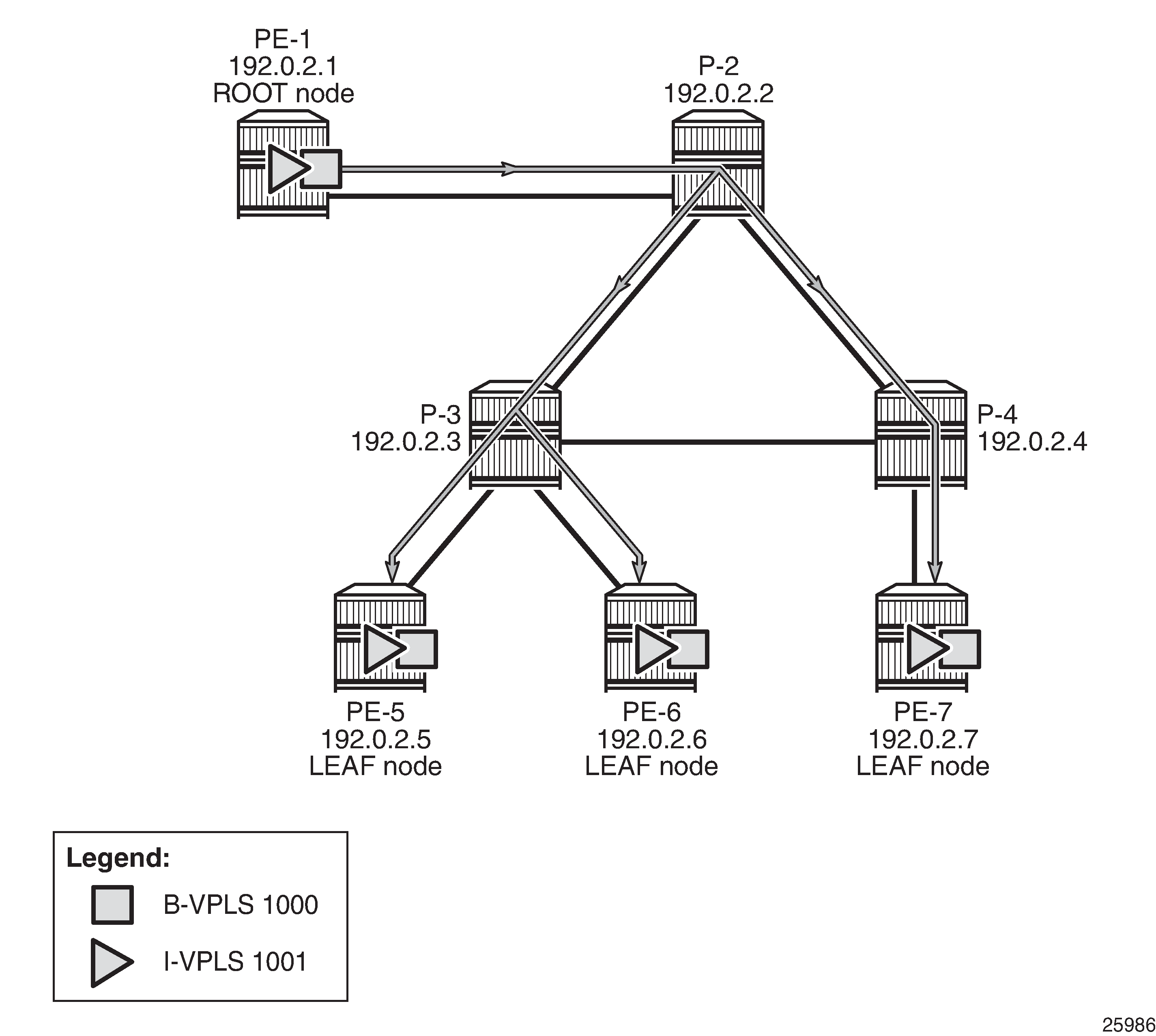
P2MP mLDP tunnels can also be used in PBB-EVPN services. In Release 14.0, the use of provider-tunnel inclusive mldp is only for the default multicast list; no per-ISID IMET-P2MP routes are supported.
The Backbone (B) -VPLS still uses Multicast Forwarding Information Bases (MFIBs) for ISIDs using IR.
If an ISID policy is configured in the B-VPLS, a range of ISIDs configured with use-def-mcast use the P2MP tree, and a range of ISIDs configured with advertise-local make the router advertise IMET-IR routes for the local ISIDs in the range.
PE-1 is configured with root-and-leaf. The configuration for B-VPLS and I-VPLS is as follows:
# On PE-1:
configure {
    service {
        vpls "B-VPLS 1000" {
            admin-state enable
            service-id 1000
            customer "1"
            service-mtu 2000
            pbb-type b-vpls
            pbb {
                source-bmac {
                    address 00:00:00:00:00:01
                }
            }
            bgp 1 {
            }
            bgp-evpn {
                evi 1000
                mpls 1 {
                    admin-state enable
                    auto-bind-tunnel {
                        resolution any
                    }
                }
            }
            provider-tunnel {
                inclusive {
                    admin-state enable
                    owner bgp-evpn-mpls
                    root-and-leaf true
                    mldp
                }
            }
            isid-policy {
                entry 10 {
                    advertise-local false
                    use-def-mcast true
                    range {
                        start 1001
                        end 2000
                    }
                }
            }
        }
        vpls "I-VPLS 1001" {
            admin-state enable
            service-id 1001
            customer "1"
            pbb-type i-vpls
            pbb {
                backbone-vpls "B-VPLS 1000" {
                    isid 1001
                }
            }
            sap 1/2/c3/1 {    # sap for ingress traffic from STC
            }
        }
    }
In this example, ISIDs in the range from 1001 to 2000 use the P2MP tree (use-def-mcast) and the router does not advertise the IMET-IR routes for the local ISIDs included in that range (no advertise-local). Any other local ISID advertises an IMET-IR and uses the MFIB to forward BUM packets to the remote EVPN-MPLS bindings created by IMET-IR routes.
The configuration on the leaf nodes PE-5, PE-6, and PE-7 is similar to the one for the root node, except for the absence of the root-and-leaf setting (which is default), as follows:
# On PE-5:
configure {
    service {
        vpls "B-VPLS 1000" {
            admin-state enable
            service-id 1000
            customer "1"
            service-mtu 2000
            pbb-type b-vpls
            pbb {
                source-bmac {
                    address 00:00:00:00:00:05
                }
            }
            bgp 1 {
            }
            bgp-evpn {
                evi 1000
                mpls 1 {
                    admin-state enable
                    auto-bind-tunnel {
                        resolution any
                    }
                }
            }
            provider-tunnel {
                inclusive {
                    admin-state enable
                    owner bgp-evpn-mpls
                    mldp
                }
            }
            isid-policy {
                entry 10 {
                    advertise-local false
                    use-def-mcast true
                    range {
                        start 1001
                        end 2000
                    }
                }
            }
        }
        vpls "I-VPLS 1001" {
            admin-state enable
            service-id 1001
            customer "1"
            pbb-type i-vpls
            pbb {
                backbone-vpls "B-VPLS 1000" {
                    isid 1001
                }
            }
            sap 1/2/c1/1:1001 {    # sap for egress traffic to VPLS 1001
            }
        }
    }
A VPLS-PMSI SDP is auto-created in the B-VPLS at the root node, as follows:
[/]
A:admin@PE-1# show service id 1000 sdp

===============================================================================
Services: Service Destination Points
===============================================================================
SdpId            Type     Far End addr    Adm     Opr       I.Lbl     E.Lbl
-------------------------------------------------------------------------------
32767:4294967292 VplsPmsi not applicable  Up      Up        None      3
-------------------------------------------------------------------------------
Number of SDPs : 1
-------------------------------------------------------------------------------
===============================================================================
The default multicast list for the B-VPLS 1000 can be retrieved on root node and leaf nodes, for instance for leaf node PE-5, as follows:
[/]
A:admin@PE-5# tools dump service id 1000 evpn-mpls default-multicast-list
-------------------------------------------------------------------------
TEP Address                              Egr Label
                                         Transport
-------------------------------------------------------------------------
192.0.2.1                                524283
                                         ldp
192.0.2.6                                524286
                                         ldp
192.0.2.7                                524281
                                         ldp
-------------------------------------------------------------------------
IGMP snooping can be enabled in the I-VPLS 1001 on all PEs, as follows:
configure {
    service {
        vpls "I-VPLS 1001" {
            igmp-snooping {
                admin-state enable
            }
After IGMP snooping is enabled, the multicast stream is not flooded anymore to any receivers until they send an IGMP report for the multicast stream.
On each PE, the logical interface B-EVPN-MPLS is added as a single IGMP snooping interface and treated as an mrouter, as follows:
[/]
A:admin@PE-5# show service id 1001 igmp-snooping base

===============================================================================
IGMP Snooping Base info for service 1001
===============================================================================
Admin State : Up
Querier     : 172.16.0.55 on SAP 1/2/c1/1:1001
SBD service : N/A
Evpn-proxy  : Disabled
-------------------------------------------------------------------------------
Port                       Oper MRtr Pim  Send Max  Max  Max   MVR       Num
Id                         Stat Port Port Qrys Grps Srcs Grp   From-VPLS Grps
                                                         Srcs
-------------------------------------------------------------------------------
b-evpn-mpls
                           Up   Yes  No   N/A  N/A  N/A  N/A   N/A       N/A
sap:1/2/c1/1:1001          Up   Yes  No   No   None None None  Local     0
===============================================================================
PE-5 has a receiver that sent an IGMP report for a multicast group in I-VPLS 1001 on SAP 1/2/c1/1:1001 and this SAP is an mrouter port. On PE-6, there is no receiver that sent IGMP reports; therefore, the only mrouter port corresponds to the B-EVPN-MPLS logical interface, as follows:
[/]
A:admin@PE-6# show service id 1001 igmp-snooping base

===============================================================================
IGMP Snooping Base info for service 1001
===============================================================================
Admin State : Up
Querier     : 172.16.0.55 on evpn-mpls
SBD service : N/A
Evpn-proxy  : Disabled
-------------------------------------------------------------------------------
Port                       Oper MRtr Pim  Send Max  Max  Max   MVR       Num
Id                         Stat Port Port Qrys Grps Srcs Grp   From-VPLS Grps
                                                         Srcs
-------------------------------------------------------------------------------
b-evpn-mpls
                           Up   Yes  No   N/A  N/A  N/A  N/A   N/A       N/A
sap:1/2/c1/1:1001          Up   No   No   No   None None None  Local     0
===============================================================================
PE-5 has a local mrouter 172.16.0.55 on SAP 1/2/c1/1:1001, as follows:
[/]
A:admin@PE-5# show service id 1001 igmp-snooping mrouters

===============================================================================
IGMP Snooping Multicast Routers for service 1001
===============================================================================
MRouter          Port Id                    Up Time        Expires   Version
-------------------------------------------------------------------------------
172.16.0.55      sap:1/2/c1/1:1001          0d 00:03:24    216s      3
-------------------------------------------------------------------------------
Number of mrouters: 1
===============================================================================
On PE-6, mrouter 172.16.0.55 is not local; therefore, the EVPN-MPLS logical interface is used, as follows:
[/]
A:admin@PE-6# show service id 1001 igmp-snooping mrouters

===============================================================================
IGMP Snooping Multicast Routers for service 1001
===============================================================================
MRouter          Port Id                    Up Time        Expires   Version
-------------------------------------------------------------------------------
172.16.0.55      evpn-mpls                  0d 00:03:25    215s      3
-------------------------------------------------------------------------------
Number of mrouters: 1
===============================================================================
Conclusion
Service providers are migrating their existing VPN services to EVPN and expect at least the same capabilities in EVPN, including the forwarding of BUM traffic. Ingress replication is a good mechanism for broadcast and unknown unicast traffic in EVPN networks, but not efficient for multicast applications. EVPN P2MP mLDP offers efficiency for multicast, using composite tunnels combining the benefits of P2MP mLDP and IR.