EVPN-MPLS Interconnect for EVPN-VXLAN VPLS Services
This chapter provides information about EVPN-MPLS Interconnect for EVPN-VXLAN VPLS Services.
Topics in this chapter include:
Applicability
This chapter was initially written for SR OS Release 14.0.R5, but the MD-CLI in the current edition is based on SR OS Release 21.2.R1.
Chapters EVPN for MPLS Tunnels and EVPN for VXLAN Tunnels (Layer 2) are prerequisite reading.
Overview
When EVPN-MPLS is deployed in the WAN, many service providers are looking for a way to integrate existing Layer 2 EVPN-VXLAN based data center services into the WAN, while keeping the end-to-end advantages of EVPN. The IETF draft-ietf-bess-dci-evpn-overlay describes how to provide Layer 2 connectivity for EVPN-overlay data centers in different ways. This chapter follows section 4.4 of that document, in which EVPN-MPLS is used in the same VPLS service that terminates overlay (VXLAN) tunnels.
To provide EVPN-MPLS connectivity to VPLS services terminating EVPN-VXLAN, SR OS supports the configuration of BGP-EVPN MPLS and BGP-EVPN VXLAN at the same time by adding two BGP instances to the service. Two BGP instances are supported in the same VPLS at most. BGP-EVPN MPLS and BGP-EVPN VXLAN can both use BGP instance 1 or 2, but they must use different instances.
In a service with EVPN-VXLAN and EVPN-MPLS, the config>service>vpls>bgp-evpn>mpls 2 command allows the user to associate BGP-EVPN MPLS to BGP instance 2, while BGP-EVPN VXLAN is associated to BGP instance 1, and therefore, have both encapsulations simultaneously enabled in the same service. Either BGP instance 1 or 2 can be associated to BGP-EVPN VXLAN or MPLS, but they must be different. When the two BGP instances are successfully added to the same VPLS service, the service behaves as follows:
-
MAC/IP routes received on one instance will be "consumed" (accepted, imported, and installed in FDB) and re-advertised in the other instance, as long as the route is the best route for a specific MAC or MAC/IP.
-
Inclusive multicast routes are independently generated for each BGP instance.
-
From a data plane perspective, EVPN-MPLS and EVPN-VXLAN destinations are instantiated in different implicit Split-Horizon Groups (SHGs) so that traffic can be forwarded between the two SHGs, but not between destinations of the same kind. For example, traffic coming from EVPN-MPLS cannot be forwarded to other destinations in the EVPN-MPLS SHG.
The following example shows a VPLS service configured on PE-2 with two BGP instances and both encapsulations, VXLAN and MPLS, configured at the same time:
configure {
    service {
        vpls "VPLS 1" {
            description "evpn-mpls and evpn-vxlan in the same service"
            admin-state enable
            service-id 1
            customer "1"
            vxlan {
                instance 1 {
                    vni 1
                }
            }
            bgp 1 {
                route-distinguisher "10:1"
                route-target {
                    export "target:64500:1"
                    import "target:64500:1"
                }
            }
            bgp 2 {
                route-distinguisher "10:2"
                route-target {
                    export "target:64500:1"
                    import "target:64500:1"
                }
            }
            bgp-evpn {
                evi 1
                vxlan 1 {
                    admin-state enable
                    vxlan-instance 1
                }
                mpls 2 {
                    admin-state enable
                    auto-bind-tunnel {
                        resolution any
                    }
                }
            }
In the preceding example
-
bgp 1 is the default BGP instance.
-
bgp 2 is the additional instance that is required when both BGP-EVPN VXLAN and BGP-EVPN MPLS are enabled in the service.
-
The same commands supported under BGP instance 1 exist for this second BGP instance, with the following considerations:
-
pw-template-binding – the pseudowire (PW) template binding can only exist in BGP instance 1; it is not supported in BGP instance 2. Because no SDP-bindings can exist in a VPLS service with two BGP instances, the pw-template-binding command is ineffective in this configuration.
-
route-distinguisher – the route distinguisher in both BGP instances must be different.
-
route-target – the route target in both instances can be the same or different.
-
vsi-import and vsi-export – import and export policies can also be defined for either BGP instance.
-
-
The mpls 2 command will assign BGP instance 2 to MPLS. The VPLS configuration can only be committed if the BGP instance associated with MPLS has a different route distinguisher than the BGP instance associated with VXLAN.
-
The evi can still be used for auto-derivation of RD/RT on BGP instance 1 and auto-derivation of RT (not RD) on BGP instance 2. Auto-RD or an explicitly configured RD is needed in BGP instance 2.
Configuration
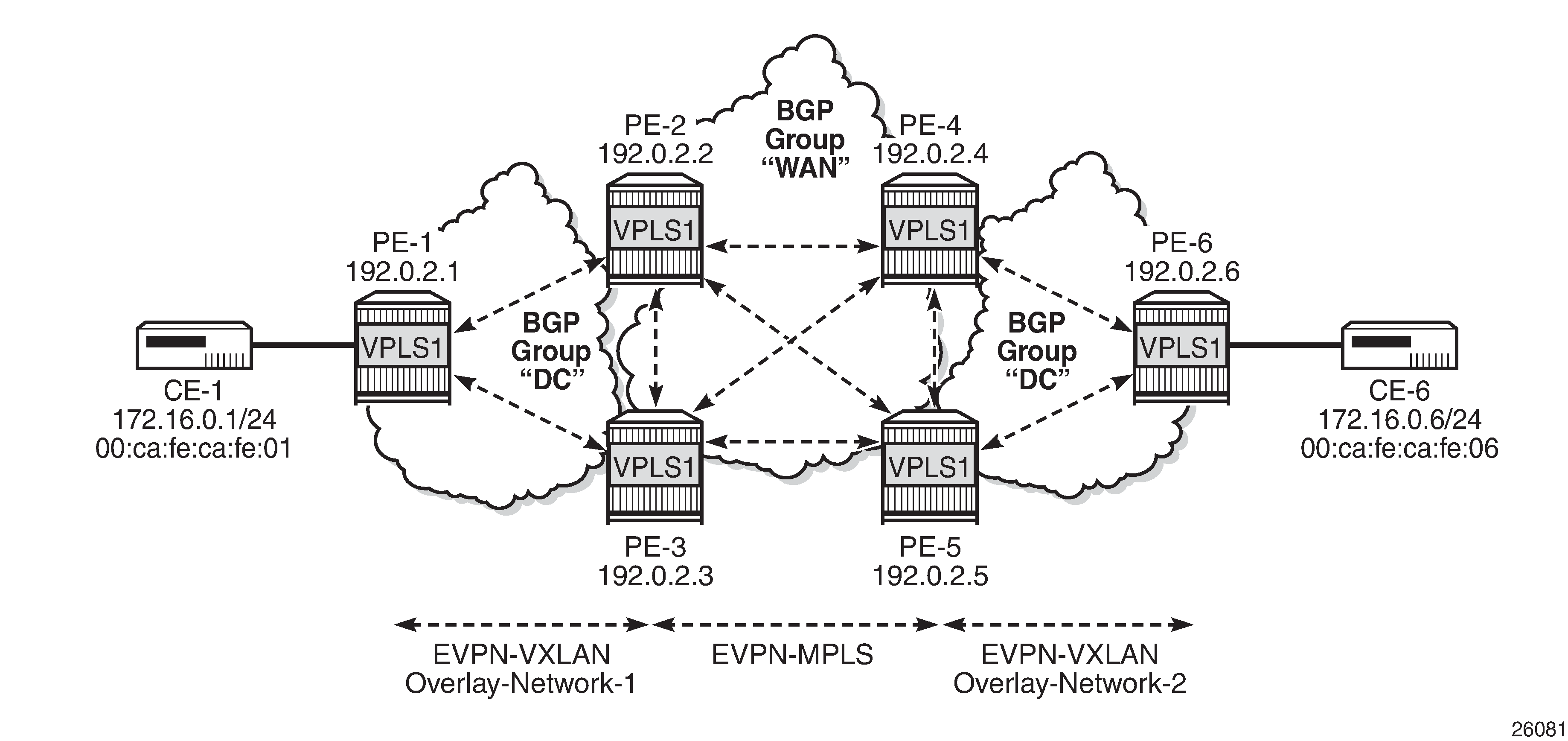
EVPN-MPLS interconnect for EVPN-VXLAN - example topology shows the example topology that will be used throughout this chapter, as well as the BGP peering topology. PE-1, PE-2, and PE-3 simulate a data center, shown as Overlay-Network-1, where PE-2 and PE-3 are DC GWs. In the same way, PE-4, PE-5, and PE-6 simulate a remote data center, Overlay-Network-2. Inside each DC, EVPN-VXLAN is used.
The two DC GW pairs are connected by EVPN-MPLS; therefore, CE-1 and CE-6 are end-to-end connected by EVPN without any VLAN or PW hand-off, maintaining all the EVPN advantages across the DC Interconnect (DCI) network.
The example topology consists of six 7750 SR routers with the following initial configuration:
-
Hybrid ports (they could have been network type too) are interconnecting the six PEs with configured router interfaces.
-
The six PEs are running IS-IS and creating point-to-point adjacencies.
-
Link LDP is configured in the core, among PE-2, PE-3, PE-4, and PE-5, while PE-1 and PE-6 are only running VXLAN.
-
EVPN uses MP-BGP for exchanging reachability at service level. Therefore, BGP peering sessions must be established among the PEs for the EVPN family. EVPN-MPLS interconnect for EVPN-VXLAN - example topology shows the peering sessions established among the six PEs. Although usually a Route-Reflector (RR) is used in each DC and another RR in the WAN, in this example, there are direct peering sessions in each DC and in the WAN.
The following output shows the BGP configuration of PE-2. The BGP configuration on the rest of the DC GWs (PE-3, PE-4, and PE-5) is similar:
# on PE-2:
configure {
    router "Base" {
        autonomous-system 64500
        bgp {
            vpn-apply-export true
            vpn-apply-import true
            rapid-withdrawal true
            family {
                ipv4 false
                evpn true
            }
            rapid-update {
                evpn true
            }
            group "DC" {
                type internal
                import {
                    policy ["drop SOO-DCGW-23"]
                }
                export {
                    policy ["allow only vxlan and add SOO"]
                }
            }
            group "WAN" {
                type internal
                import {
                    policy ["drop SOO-DCGW-23"]
                }
                export {
                    policy ["allow only mpls and add SOO"]
                }
            }
            neighbor "192.0.2.1" {
                group "DC"
            }
            neighbor "192.0.2.3" {
                group "DC"
            }
            neighbor "192.0.2.4" {
                group "WAN"
            }
            neighbor "192.0.2.5" {
                group "WAN"
            }
        }
Two different BGP groups are configured: DC and WAN. The DC group contains the DC neighbors (including the peer DC GW) and the WAN group contains the WAN neighbors. This grouping makes the use of policies easier. These policies will be explained in the section The mandatory use of BGP policies in the multi-homed anycast solution.
The following output shows the BGP configuration of PE-1. PE-6 has a similar BGP configuration.
# on PE-1:
configure {
    router "Base" {
        autonomous-system 64500
        bgp {
            rapid-withdrawal true
            family {
                ipv4 false
                evpn true
            }
            rapid-update {
                evpn true
            }
            group "DC" {
                type internal
            }
            neighbor "192.0.2.2" {
                group "DC"
            }
            neighbor "192.0.2.3" {
                group "DC"
            }
        }
VPLS service configuration
After the base infrastructure (interfaces, IGP, LDP in the core, and BGP) is configured, the services can be added. The configuration example in this section will use VPLS 1 as the service to be interconnected across the two DCs.
PE-1 and PE-6 have a regular EVPN-VXLAN configuration; DCI connectivity provided by EVPN-MPLS is completely transparent to them. The configuration of VPLS 1 in PE-1 is as follows:
# on PE-1:
configure {
    service {
        vpls "VPLS 1" {
            admin-state enable
            service-id 1
            customer "1"
            vxlan {
                instance 1 {
                    vni 1
                }
            }
            bgp 1 {
            }
            bgp-evpn {
                evi 1
                vxlan 1 {
                    admin-state enable
                    vxlan-instance 1
                }
            }
            sap 1/2/1:1 {
            }
        }
See the EVPN for VXLAN Tunnels (Layer 2) chapter for a complete description of the EVPN-VXLAN commands.
The configuration on PE-2, PE-3, PE-4, and PE-5 (see EVPN-MPLS interconnect for EVPN-VXLAN - example topology) enables EVPN-VXLAN and EVPN-MPLS in the same VPLS service. As an example, the VPLS 1 configuration on PE-2 is as follows:
# on PE-2:
configure {
    service {
        vpls "VPLS 1" {
            admin-state enable
            service-id 1
            customer "1"
            vxlan {
                instance 1 {
                    vni 1
                }
            }
            bgp 1 {
                route-distinguisher "64500:1"
            }
            bgp 2 {
                route-distinguisher "64500:2"
            }
            bgp-evpn {
                evi 1
                incl-mcast-orig-ip 23.23.23.23
                vxlan 1 {
                    admin-state enable
                    vxlan-instance 1
                }
                mpls 2 {
                    admin-state enable
                    ingress-replication-bum-label true
                    auto-bind-tunnel {
                        resolution any
                    }
                }
            }
        }
As described in the Overview section, the preceding configuration enables the router to create EVPN-VXLAN and EVPN-MPLS destinations in the same VPLS service, but in different SHGs. In addition to the bgp 2 commands already described in the Overview section, the incl-mcast-orig-ip command is added in the configuration. If configured, this command will change the originating IP address in the inclusive multicast routes (from the default system IP) for both BGP instances. The section Multi-homed anycast configuration for dual BGP-instance VPLS services describes why this command is added.
The following section provides a detailed description of the expected behavior for EVPN routes that are imported and exported on dual BGP instance VPLS services.
EVPN route handling in dual BGP-instance VPLS services
This section describes how the BGP-EVPN routes are processed in dual BGP instance services.
Usually, the router validates the received tunnel encapsulation (from the RFC 5512 Extended Community) with the configured encapsulation of the service/BGP-instance. Therefore, an EVPN-VXLAN route will not get imported into the BGP-EVPN MPLS instance and vice-versa. This is also how the different EVPN route types are handled in dual BGP instance services:
-
Route type 1 - auto-discovery routes
AD per-EVI routes are never generated by services with two BGP instances (because no Ethernet Segment (ES) can be associated with the dual BGP instance service). However, AD per-EVI routes can still be received from the EVPN-MPLS peers and are processed as usual. Therefore, a VPLS service with two BGP instances will still support aliasing/backup and AD per-ES checking procedures for a remote multi-homed ES, as described in the EVPN for MPLS Tunnels chapter. However, in the example in EVPN-MPLS interconnect for EVPN-VXLAN - example topology, PE-6 does not have any local multi-homed ES configured; therefore, no AD per-EVI routes are present in this example.
-
Route type 2 - MAC/IP routes
MAC/IP routes received on one of the two BGP instances will be imported and the MAC addresses added to the FDB according to the existing selection rules. If the MAC address is active (therefore installed in the FDB), it will be re-advertised in the other BGP instance with the BGP attributes of the other BGP instance (new route target if different, new route distinguisher, and so on). The bgp-evpn>routes>mac-ip>advertise command will govern the advertisement of MAC addresses in either BGP instance.
The MAC/IP route redistribution across BGP instances is performed according to the following rules:
-
A MAC route is redistributed only if it is the best route according to the EVPN selection rules in the EVPN for MPLS Tunnels chapter.
-
Assuming a specific MAC route is the best one and has to be redistributed, the MAC/IP information along with the sticky bit is propagated in the redistribution.
-
A change in the MAC/IP route sequence number or sticky bit in one instance is updated in the other instance, as long as that route is the best MAC route for the route key.
-
When a MAC address moves within the EVPN-VXLAN (or the EVPN-MPLS) network, the MAC route is received on the same BGP instance where it was previously received, but now with a higher sequence number. In this case, the MAC route will be redistributed with the new sequence number. However, a router with two BGP instances in the same service will not detect any duplicate MAC on the EVPN-VXLAN and EVPN-MPLS networks.
As an example, the following output shows the debug of a MAC/IP route received on PE-2, on the BGP instance for EVPN-VXLAN on VPLS 1, and how the route is re-advertised to the BGP instance used for MPLS (with a different next-hop, route distinguisher, label, and BGP tunnel encapsulation):
# on PE-2:
14 2021/03/16 17:31:10.452 CET MINOR: DEBUG #2001 Base Peer 1: 192.0.2.1
"Peer 1: 192.0.2.1: UPDATE
Peer 1: 192.0.2.1 - Received BGP UPDATE:
    Withdrawn Length = 0
    Total Path Attr Length = 81
    Flag: 0x90 Type: 14 Len: 44 Multiprotocol Reachable NLRI:
        Address Family EVPN
        NextHop len 4 NextHop 192.0.2.1
        Type: EVPN-MAC Len: 33 RD: 192.0.2.1:1 ESI: ESI-0, tag: 0, mac len: 48
                       mac: 00:ca:fe:ca:fe:01, IP len: 0, IP: NULL, label1: 1
    Flag: 0x40 Type: 1 Len: 1 Origin: 0
    Flag: 0x40 Type: 2 Len: 0 AS Path:
    Flag: 0x40 Type: 5 Len: 4 Local Preference: 100
    Flag: 0xc0 Type: 16 Len: 16 Extended Community:
        target:64500:1
        bgp-tunnel-encap:VXLAN
"
15 2021/03/16 17:31:10.453 CET MINOR: DEBUG #2001 Base Peer 1: 192.0.2.4 "Peer 1: 192.0.2.4: UPDATE Peer 1: 192.0.2.4 - Send BGP UPDATE: Withdrawn Length = 0 Total Path Attr Length = 89 Flag: 0x90 Type: 14 Len: 44 Multiprotocol Reachable NLRI: Address Family EVPN NextHop len 4 NextHop 192.0.2.2 Type: EVPN-MAC Len: 33 RD: 64500:2 ESI: ESI-0, tag: 0, mac len: 48 mac: 00:ca:fe:ca:fe:01, IP len: 0, IP: NULL, label1: 8388528 Flag: 0x40 Type: 1 Len: 1 Origin: 0 Flag: 0x40 Type: 2 Len: 0 AS Path: Flag: 0x40 Type: 5 Len: 4 Local Preference: 100 Flag: 0xc0 Type: 16 Len: 24 Extended Community: origin:64500:23 target:64500:1 bgp-tunnel-encap:MPLS "16 2021/03/16 17:31:10.453 CET MINOR: DEBUG #2001 Base Peer 1: 192.0.2.5 "Peer 1: 192.0.2.5: UPDATE Peer 1: 192.0.2.5 - Send BGP UPDATE: Withdrawn Length = 0 Total Path Attr Length = 89 Flag: 0x90 Type: 14 Len: 44 Multiprotocol Reachable NLRI: Address Family EVPN NextHop len 4 NextHop 192.0.2.2 Type: EVPN-MAC Len: 33 RD: 64500:2 ESI: ESI-0, tag: 0, mac len: 48 mac: 00:ca:fe:ca:fe:01, IP len: 0, IP: NULL, label1: 8388528 Flag: 0x40 Type: 1 Len: 1 Origin: 0 Flag: 0x40 Type: 2 Len: 0 AS Path: Flag: 0x40 Type: 5 Len: 4 Local Preference: 100 Flag: 0xc0 Type: 16 Len: 24 Extended Community: origin:64500:23 target:64500:1 bgp-tunnel-encap:MPLS " -
-
Route type 3 - inclusive multicast routes
EVPN Inclusive Multicast Ethernet Tag (IMET) routes are generated independently for each BGP instance with the correct BGP tunnel encapsulation extended community and the tunnel type associated to the BGP instance; for example, Ingress Replication (IR), P2MP mLDP, or Assisted Replication (AR):
-
On the EVPN-VXLAN BGP instance, IR or AR IMET routes are supported.
-
When assisted-replication replicator is enabled and the received VXLAN broadcast and multicast packets contain an IP DA = AR-IP, the DC GW will send the packets back to VXLAN (but not to the VXLAN termination end-point (VTEP) from where the packet is received) in addition to the EVPN-MPLS destinations.
-
If assisted-replication replicator is used on the DC GWs, the AR-IP (configure>service>system>vxlan>assisted-replication>ip-address) must be a loopback different from the router's system IP and the configured bgp-evpn>incl-mcast-orig-ip. The two AR-IP addresses in the DC GW pair do not need to be the same IP address.
-
-
On the EVPN-MPLS BGP instance, IR, P2MP mLDP, or composite IMET routes are supported.
-
Following is the behavior when the incl-mcast-orig-ip command is used:
-
The configured IP in the incl-mcast-orig-ip command is encoded in the originating IP field of the IMET routes for IR, P2MP, and composite routes for both BGP instances.
-
The originating IP field of the IMET AR routes is still derived from the configured service>system>vxlan>assisted-replication>ip-address value.
-
-
The received IMET routes will be processed in the following way depending on their type:
-
IMET-IR routes: the EVPN destination (MPLS or VXLAN) is set up based on the NLRI next-hop.
-
IMET-P2MP routes: the Provider Multicast Service Interface (PMSI) Tunnel Attribute (PTA) tunnel ID will be used to join the mLDP tree (as mLDP FEC in the LDP mapping messages).
-
IMET-P2MP-IR (composite) routes: the PTA tunnel ID is used to join the mLDP tree. The NLRI next-hop is used to build the EVPN destination.
-
IMET-AR routes: the NLRI next-hop is used to build the EVPN-VXLAN destination.
-
-
Upon reception of two IMET routes with similar information, the router behaves as follows:
-
If the router receives two IMET routes with the same originating IP, different RDs, and different NLRI next-hops, it will set up two EVPN destinations, one to each next-hop.
-
If the router gets two IMET routes with the same originating IP, different RDs, but the same next-hop, it will set up only one EVPN destination.
-
The router will not set up an EVPN destination to its DC GW peer if the received originating IP matches its own originating IP, regardless of whether the local RD and the remote RD are the same or different. This enables the use of the redundant anycast solution that is described in the following section: Multi-homed anycast configuration for dual BGP-instance VPLS services.
-
-
-
Route type 4 - ES routes
ESs are supported in routers where dual BGP-instance services exist. However, because dual BGP-instance VPLS services do not support SDP-bindings, ESs and ES routes are not relevant to these types of services.
-
Route type 5 - IP-prefix routes
R-VPLS services are not supported along with dual BGP instances; therefore, IP-prefix routes are neither generated nor processed by the service.
Multi-homed anycast configuration for dual BGP-instance VPLS services
Services with EVPN-MPLS and EVPN-VXLAN SHGs are specified in draft-ietf-bess-dci-evpn-overlay and the associated multi-homing solution is also described in the same draft. That multi-homing solution is based on an interconnect ES that allows all-active and single-active multi-homed EVPN networks as well as local attachment circuits in the DC GWs (SAP/SDP-bindings).
This chapter was initially written for SR OS Release 14.0.R5 and interconnect ESs were not supported in that release. Therefore, an anycast solution is used to provide redundancy. This anycast solution is based on the two PE DC GWs in the redundant pair being configured to advertised MAC/IP and IMET routes with the same route key, so that the remote PEs will only pick up one of the two anycast DC GWs when sending unicast or BUM traffic, and no loop or packet duplication is created.
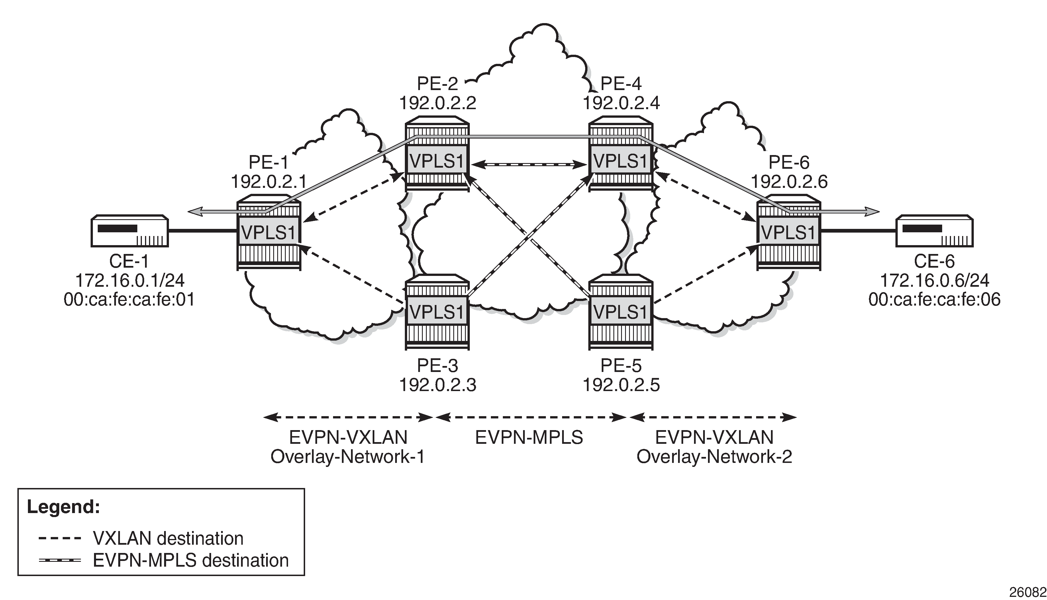
EVPN destinations created on multi-homed anycast DC GWs is an example of how multi-homing can be achieved for dual BGP-instance VPLS services. The figure also shows the EVPN destinations created and their direction (see the arrows). For instance, only one EVPN multicast destination is created for PE-1, PE-2, or PE-4. Therefore, BUM traffic sent by CE-1 will be sent via PE-2, PE-4, and PE-6 only, and no duplication or loops occur.
The following output shows the VPLS 1 configuration on PE-2 and PE-3 so that this anycast redundancy can be realized. The route distinguishers as well as the incl-mcast-orig-ip addresses must match between the two PEs in the redundant pair. VPLS 1 is configured on PE-2 as follows:
# on PE-2:
configure {
    service {
        vpls "VPLS 1" {
            admin-state enable
            service-id 1
            customer "1"
            vxlan {
                instance 1 {
                    vni 1
                }
            }
            bgp 1 {
                route-distinguisher "64500:1"
            }
            bgp 2 {
                route-distinguisher "64500:2"
            }
            bgp-evpn {
                evi 1
                incl-mcast-orig-ip 23.23.23.23
                vxlan 1 {
                    admin-state enable
                    vxlan-instance 1
                }
                mpls 2 {
                    admin-state enable
                    ingress-replication-bum-label true
                    auto-bind-tunnel {
                        resolution any
                    }
                }
            }
        }
The VPLS 1 configuration on PE-3 is as follows:
# on PE-3:
configure {
    service {
        vpls "VPLS 1" {
            admin-state enable
            service-id 1
            customer "1"
            vxlan {
                instance 1 {
                    vni 1
                }
            }
            bgp 1 {
                route-distinguisher "64500:1"
            }
            bgp 2 {
                route-distinguisher "64500:2"
            }
            bgp-evpn {
                evi 1
                incl-mcast-orig-ip 23.23.23.23
                vxlan 1 {
                    admin-state enable
                    vxlan-instance 1
                }
                mpls 2 {
                    admin-state enable
                    ingress-replication-bum-label true
                    auto-bind-tunnel {
                        resolution any
                    }
                }
            }
        }
The VPLS 1 configuration on PE-4 is as follows:
# on PE-4:
configure {
    service {
        vpls "VPLS 1" {
            admin-state enable
            service-id 1
            customer "1"
            vxlan {
                instance 1 {
                    vni 1
                }
            }
            bgp 1 {
                route-distinguisher "64501:1"
            }
            bgp 2 {
                route-distinguisher "64501:2"
            }
            bgp-evpn {
                evi 1
                incl-mcast-orig-ip 45.45.45.45
                vxlan 1 {
                    admin-state enable
                    vxlan-instance 1
                }
                mpls 2 {
                    admin-state enable
                    ingress-replication-bum-label true
                    auto-bind-tunnel {
                        resolution any
                    }
                }
            }
        }
The VPLS 1 configuration on PE-5 is as follows:
# on PE-5:
configure {
    service {
        vpls "VPLS 1" {
            admin-state enable
            service-id 1
            customer "1"
            vxlan {
                instance 1 {
                    vni 1
                }
            }
            bgp 1 {
                route-distinguisher "64501:1"
            }
            bgp 2 {
                route-distinguisher "64501:2"
            }
            bgp-evpn {
                evi 1
                incl-mcast-orig-ip 45.45.45.45
                vxlan 1 {
                    admin-state enable
                    vxlan-instance 1
                }
                mpls 2 {
                    admin-state enable
                    ingress-replication-bum-label true
                    auto-bind-tunnel {
                        resolution any
                    }
                }
            }
        }
Based on the preceding configuration example, the DC GWs behavior in this scenario is as follows:
-
PE-2 and PE-3 both send IMET IR routes to the other PEs with the same route key but a different next-hop. The route key in IMET routes comprises [RD, Ethernet tag, originator-IP/length], which in this case will be [64500:1, 0, 23.23.23.23/32] for the EVPN-VXLAN IMET routes and [64500:2, 0, 23.23.23.23/32] for the EVPN-MPLS IMET routes.
-
In the same way, PE-2 and PE-3 both send MAC/IP routes to the other PEs with the same route key but a different next-hop. The route key comprises [RD, Ethernet tag, MAC/MAC-length, IP/IP-length].
The configuration of the same incl-mcast-orig-ip address and RDs in both DC GWs enables the anycast solution due to the following:
-
The configured originating IP (for example, 23.23.23.23 in PE-2 and PE-3) is not required to be a reachable IP address, which forces the remote PEs (or RRs if they exist) to select only one of the two DC GWs for BUM traffic (based on regular BGP selection). In this example, the remote PEs will select the PE-2 IMET route and create only one destination. The following output shows the IMET routes received by PE-1 (only the PE-2 route is used) and the created EVPN-VXLAN destination to PE-2. The same behavior could have been shown in the rest of the PEs.
[/]
A:admin@PE-1# show router bgp routes evpn incl-mcast
===============================================================================
 BGP Router ID:192.0.2.1        AS:64500       Local AS:64500
===============================================================================
 Legend -
 Status codes  : u - used, s - suppressed, h - history, d - decayed, * - valid
                 l - leaked, x - stale, > - best, b - backup, p - purge
 Origin codes  : i - IGP, e - EGP, ? - incomplete

===============================================================================
BGP EVPN Inclusive-Mcast Routes
===============================================================================
Flag  Route Dist.         OrigAddr
      Tag                 NextHop
-------------------------------------------------------------------------------
u*>i  64500:1             23.23.23.23
      0                   192.0.2.2

*>i   64500:1             23.23.23.23
      0                   192.0.2.3

-------------------------------------------------------------------------------
Routes : 2
===============================================================================
[/]A:admin@PE-1# show service id 1 vxlan destinations =============================================================================== Egress VTEP, VNI =============================================================================== Instance VTEP Address Egress VNI EvpnStatic Num Mcast Oper State L2 PBR SupBcasDom MACs ------------------------------------------------------------------------------- 1 192.0.2.2 1 evpn 1 BUM Up No No ------------------------------------------------------------------------------- Number of Egress VTEP, VNI : 1 ------------------------------------------------------------------------------- =============================================================================== =============================================================================== BGP EVPN-VXLAN Ethernet Segment Dest =============================================================================== Instance Eth SegId Num. Macs Last Change ------------------------------------------------------------------------------- No Matching Entries =============================================================================== -
Due to the same RD and originating IP configured on PE-2 and PE3 (similarly in PE-4 and PE-5), the DC GW redundant PEs will never establish an EVPN destination between each other. PE-2 only sets up EVPN multicast destinations to PE-1 and PE-4, as follows:
[/]
A:admin@PE-2# show service id 1 vxlan destinations

===============================================================================
Egress VTEP, VNI
===============================================================================
Instance    VTEP Address                            Egress VNI  EvpnStatic Num
 Mcast       Oper State                              L2 PBR     SupBcasDom MACs
-------------------------------------------------------------------------------
1           192.0.2.1                               1           evpn       1
 BUM         Up                                      No          No
-------------------------------------------------------------------------------
Number of Egress VTEP, VNI : 1
-------------------------------------------------------------------------------
===============================================================================

===============================================================================
BGP EVPN-VXLAN Ethernet Segment Dest
===============================================================================
Instance  Eth SegId                       Num. Macs     Last Change
-------------------------------------------------------------------------------
No Matching Entries
===============================================================================
[/] A:admin@PE-2# show service id 1 evpn-mpls =============================================================================== BGP EVPN-MPLS Dest =============================================================================== TEP Address Egr Label Num. MACs Mcast Last Change Transport:Tnl Sup BCast Domain ------------------------------------------------------------------------------- 192.0.2.4 524282 0 bum 03/16/2021 17:29:38 ldp:65538 No 192.0.2.4 524283 1 none 03/16/2021 17:31:34 ldp:65538 No ------------------------------------------------------------------------------- Number of entries : 2 ------------------------------------------------------------------------------- =============================================================================== ---snip--- -
Likewise, when the two redundant PEs receive the same MAC/IP route, they will both re-advertise it with the same route key, forcing the remote PEs to pick up only one of the two (based on regular BGP selection) and create only one EVPN destination (if different from the multicast destination). In the following example, PE-6 advertised the CE-6 MAC address, that is, re-advertised by PE-4/PE-5 and then by PE-2/PE-3, but only one of the routes is selected at each hop. The following output shows that PE-1 selects the PE-2 MAC/IP route (see the "used" flag) and uses the existing EVPN destination to PE-2:
[/]
A:admin@PE-1# show router bgp routes evpn mac
===============================================================================
 BGP Router ID:192.0.2.1        AS:64500       Local AS:64500
===============================================================================
 Legend -
 Status codes  : u - used, s - suppressed, h - history, d - decayed, * - valid
                 l - leaked, x - stale, > - best, b - backup, p - purge
 Origin codes  : i - IGP, e - EGP, ? - incomplete

===============================================================================
BGP EVPN MAC Routes
===============================================================================
Flag  Route Dist.         MacAddr           ESI
      Tag                 Mac Mobility      Label1
                          Ip Address
                          NextHop
-------------------------------------------------------------------------------
u*>i  64500:1             00:ca:fe:ca:fe:06 ESI-0
      0                   Seq:0             VNI 1
                          n/a
                          192.0.2.2

*>i   64500:1             00:ca:fe:ca:fe:06 ESI-0
      0                   Seq:0             VNI 1
                          n/a
                          192.0.2.3

-------------------------------------------------------------------------------
Routes : 2
===============================================================================
[/] A:admin@PE-1# show service id 1 fdb detail =============================================================================== Forwarding Database, Service 1 =============================================================================== ServId MAC Source-Identifier Type Last Change Transport:Tnl-Id Age ------------------------------------------------------------------------------- 1 00:ca:fe:ca:fe:01 sap:1/2/1:1 L/30 03/16/21 17:31:10 1 00:ca:fe:ca:fe:06 vxlan-1: Evpn 03/16/21 17:31:34 192.0.2.2:1 ------------------------------------------------------------------------------- No. of MAC Entries: 2 ------------------------------------------------------------------------------- Legend: L=Learned O=Oam P=Protected-MAC C=Conditional S=Static Lf=Leaf ===============================================================================[/] A:admin@PE-1# show service id 1 vxlan destinations =============================================================================== Egress VTEP, VNI =============================================================================== Instance VTEP Address Egress VNI EvpnStatic Num Mcast Oper State L2 PBR SupBcasDom MACs ------------------------------------------------------------------------------- 1 192.0.2.2 1 evpn 1 BUM Up No No ------------------------------------------------------------------------------- Number of Egress VTEP, VNI : 1 ------------------------------------------------------------------------------- =============================================================================== =============================================================================== BGP EVPN-VXLAN Ethernet Segment Dest =============================================================================== Instance Eth SegId Num. Macs Last Change ------------------------------------------------------------------------------- No Matching Entries =============================================================================== -
As shown in the preceding outputs, the EVPN destinations are always created to the IMET or MAC/IP route's BGP next-hops, which are still the system IP address of the routers (they could have also been a loopback address). The BGP next-hops need to be reachable in their respective network: DC or WAN.
The mandatory use of BGP policies in the multi-homed anycast solution
BGP policies must be configured in a multi-homed anycast solution, such as the one described in the previous section. Without policies, the following undesired behavior would happen:
-
IMET routes with VXLAN encapsulation would be sent to the BGP peers in the MPLS network and IMET routes with MPLS encapsulation sent to BGP peers in the DC. The configured BGP policies will avoid that and make sure that the VXLAN routes are only sent to the DC and MPLS routes only to the WAN.
-
MAC/IP routes received in the VXLAN BGP instance of a DC GW would be re-advertised to the redundant DC GW in the MPLS BGP instance and the redundant DC GW would re-advertise the same MAC again into the VXLAN instance, creating a control plane loop. The same thing would happen for MAC/IP routes received in an MPLS BGP instance. The configured BGP policies will prevent a DC GW from re-advertising MAC/IP routes received from the redundant DC GW.
While service-level BGP policies (config>service>vpls>bgp>vsi-import/export) may have been configured to prevent these loops and misbehavior, the use of BGP peer-level policies (config>router>bgp>group>import/export) is recommended due to the following reasons:
-
Simplicity - BGP peer-level policies do not require any extra configuration at the service level, only at the BGP level.
-
Scalability - BGP peer-level policies scale better than VSI-level policies, because the number of services where the VSI policies should be configured may be significant.
The following policies are configured in the example used in this chapter. No policies are needed in PE-1 and PE-6; only the DC GWs must be configured.
Following are the policies and how they are applied in PE-2 and PE-3:
# on PE-2, PE-3:
configure {
    policy-options {
        community "SOO-DCGW-23" {
            member "origin:64500:23" { }
        }
        community "mpls" {
            member "bgp-tunnel-encap:MPLS" { }
        }
        community "vxlan" {
            member "bgp-tunnel-encap:VXLAN" { }
        }

/* "drop SOO-DCGW-23" will drop any EVPN route that is received from PE-3,
the other DC GW in the pair. */

        policy-statement "drop SOO-DCGW-23" {
            entry 10 {
                from {
                    family [evpn]
                    community {
                        name "SOO-DCGW-23"
                    }
                }
                action {
                    action-type reject
                }
            }
        }

/* "allow only mpls and add SOO" has a twofold objective: avoids sending EVPN-VXLAN
routes to the MPLS network and marks the advertised EVPN routes with a Site-Of-Origin extended community that identifies the DC GW pair. */

        policy-statement "allow only mpls and add SOO" {
            entry 10 {
                from {
                    family [evpn]
                    community {
                        name "vxlan"
                    }
                }
                action {
                    action-type reject
                }
            }
            entry 20 {
                from {
                    family [evpn]
                }
                action {
                    action-type accept
                    community {
                        add ["SOO-DCGW-23"]
                    }
                }
            }
        }

/* In the same way, "allow only vxlan and add SOO" avoids sending EVPN-MPLS routes
to the VXLAN network and marks the EVPN routes with a Site-Of-Origin extended
community that identifies the DC GW pair. */

        policy-statement "allow only vxlan and add SOO" {
            entry 10 {
                from {
                    family [evpn]
                    community {
                        name "mpls"
                    }
                }
                action {
                    action-type reject
                }
            }
            entry 20 {
                from {
                    family [evpn]
                }
                action {
                    action-type accept
                    community {
                        add ["SOO-DCGW-23"]
                    }
                }
            }
        }

/* The policies are properly applied at group level, as follows: */

# on PE-2, PE-3:
configure {
    router "Base" {
        bgp {
            ---snip---
            group "DC" {
                type internal
                import {
                    policy ["drop SOO-DCGW-23"]
                }
                export {
                    policy ["allow only vxlan and add SOO"]
                }
            }
            group "WAN" {
                type internal
                import {
                    policy ["drop SOO-DCGW-23"]
                }
                export {
                    policy ["allow only mpls and add SOO"]
                }
            }
            ---snip---
PE-4 and PE-5 use the same BGP peer policies, but using a Site Of Origin extended community identifying the PE-4/PE-5 pair instead of the PE-2/PE-3 pair:
# on PE-4, PE-5:
configure {
    policy-options {
        community "SOO-DCGW-45" {
            member "origin:64500:45" { }
        }
        community "mpls" {
            member "bgp-tunnel-encap:MPLS" { }
        }
        community "vxlan" {
            member "bgp-tunnel-encap:VXLAN" { }
        }
---snip---
Dual BGP instance VPLS service caveats
When two BGP instances are enabled on the same VPLS service, the following considerations apply:
-
SDP-bindings are not supported (therefore, no pw-template-binding is needed in the service). Any attempt to add an SDP-binding to a service with two BGP instances will be blocked by the CLI, as follows:
*[ex:/configure service vpls "VPLS 1" spoke-sdp 21:1] A:admin@PE-2# commit MINOR: MGMT_CORE #4001: configure service vpls "VPLS 1" - multiple bgp-evpn instances not supported with local mesh or spoke sdp -
Services that are not supported: R-VPLS, M-VPLS, I-VPLS, B-VPLS, or E-Tree VPLS
-
A consequence of not supporting R-VPLS is that no routes type 5 (IP-Prefix routes) are supported on dual BGP-instance services.
-
-
Proxy-ARP/ND is not supported.
-
BGP multi-homing is not supported.
-
Although the Assisted-Replication feature is supported on dual BGP-instance VPLS services, the Assisted-Replication configuration is only relevant to the VXLAN destinations. See section EVPN route handling in dual BGP-instance VPLS services for some considerations about how EVPN handles IMET AR routes.
In addition to the preceding restrictions, some commands have a specific behavior when two BGP instances are configured:
-
config>service>vpls>bgp-evpn>routes>mac-ip>advertise enables/disables the re-advertisement of MAC/IP routes in a BGP instance for MAC addresses that have been learned in the other BGP instance in the service.
-
config>service>vpls>bgp-evpn>routes>mac-ip>unknown-mac <boolean> enables/disables the advertisement of the unknown MAC route (MAC 00:..:00) on the BGP-EVPN VXLAN instance. The unknown MAC route is never sent to the BGP-EVPN MPLS instance.
The use of provider tunnels on multi-homed anycast solutions
The use of provider tunnels in dual BGP-instance VPLS services connecting multiple DCs is not recommended. Use of provider-tunnels between anycast DC GWs create packet duplication shows the case where the same BGP-EVPN service is configured in redundant anycast DC GWs and mLDP is used in the MPLS instance. In this case, packet duplication may occur if the configuration is not done carefully.
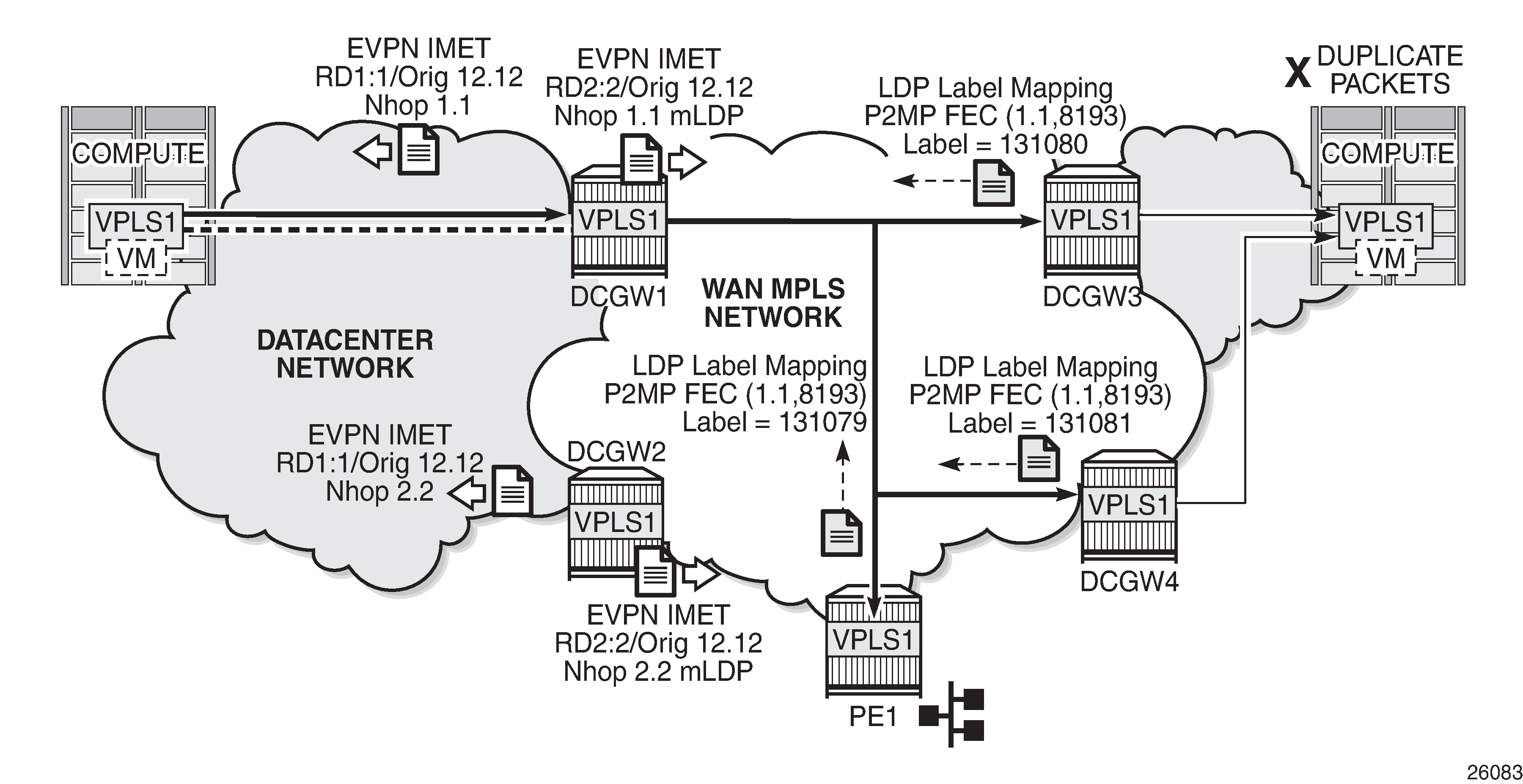
When mLDP is used along with multiple anycast multi-homing DC GWs to send BUM traffic to remote PEs, but no BUM traffic between DCs is needed, the same originating IP must be used on all the DC GWs; otherwise, packet duplication may happen. In the example in Use of provider-tunnels between anycast DC GWs create packet duplication, each pair of DC GWs, DCGW1/DCGW2 and DCGW3/DCGW4, is configured with a different originating IP (config>service>vpls>bgp-evpn>incl-mcast-orig-ip):
-
DCGW3 and DCGW4 will receive the IMET route with the same route key from DCGW1 and DCGW2.
-
DCGW3 and DCGW4 will select only one route, which will usually be the same; for example, the DCGW1 IMET route.
-
Because of that, both DCGW3 and DCGW4 will join the mLDP tree with root in DCGW1, creating packet duplication when DCGW1 sends BUM traffic.
-
Remote PE nodes with a single MPLS instance will join the mLDP tree without any issue.
To avoid the packet duplication shown by the example of Use of provider-tunnels between anycast DC GWs create packet duplication, the same originating IP may be configured in the four DCGWs, while the RD is still different per pair. By doing that:
-
In the example of Use of provider-tunnels between anycast DC GWs create packet duplication, DCGW3 and DCGW4 will never join any mLDP tree sourced from DCGW1 or DCGW2. This will prevent any packet duplication because a router will ignore IMET routes received with its own originating IP, regardless of the RD.
-
PE-1 (a remote EVPN-MPLS PE) will still join the mLDP trees from the two DCs.
-
The preceding configuration allows the use of mLDP as long as no BUM traffic is required between the two DCs. If BUM traffic is required between DCs, IR must be used.
Troubleshooting and debugging
The following show and debug commands can be used in dual BGP-instance VPLS services:
-
show router bgp routes evpn (and filters)
-
show service evpn-mpls [<TEP ip-address>]
-
show service vxlan [<TEP ip-address>]
-
show service id bgp-evpn
-
show service id evpn-mpls (and modifiers)
-
show service id vxlan destinations
-
debug router bgp update (in classic CLI)
-
show log log-id 99
See chapter EVPN for MPLS Tunnels and EVPN for VXLAN Tunnels (Layer 2) for a detailed description of these commands.
Also, in dual BGP-instance VPLS services, the show service id bgp <bgp-instance> command may help see the BGP parameters of each individual BGP instance:
[/]
A:admin@PE-2# show service id 1 bgp ?

 bgp [<number>]

 [bgp-instance] <number>
 <number>  - <1..2>

    <number> - <1..2>
[/]
A:admin@PE-2# show service id 1 bgp 1

===============================================================================
BGP Information
===============================================================================
Vsi-Import           : None
Vsi-Export           : None
Route Dist           : 64500:1
Oper Route Dist      : 64500:1
Oper RD Type         : configured
Rte-Target Import    : None                 Rte-Target Export: None
Oper RT Imp Origin   : derivedEvi           Oper RT Import   : 64500:1
Oper RT Exp Origin   : derivedEvi           Oper RT Export   : 64500:1
PW-Template Id       : None
-------------------------------------------------------------------------------
===============================================================================
[/]
A:admin@PE-2# show service id 1 bgp 2

===============================================================================
BGP Information
===============================================================================
Vsi-Import           : None
Vsi-Export           : None
Route Dist           : 64500:2
Oper Route Dist      : 64500:2
Oper RD Type         : configured
Rte-Target Import    : None                 Rte-Target Export: None
Oper RT Imp Origin   : derivedEvi           Oper RT Import   : 64500:1
Oper RT Exp Origin   : derivedEvi           Oper RT Export   : 64500:1
-------------------------------------------------------------------------------
===============================================================================
Conclusion
As service providers deploy EVPN-MPLS in the network for Ethernet local area network (E-LAN) and Ethernet point-to-point (E-Line) services, the use of EVPN-MPLS to interconnect data centers is becoming a popular option. Based on draft-ietf-bess-dci-evpn-overlay, SR OS supports the connectivity of Layer 2 EVPN-VXLAN services to an EVPN-MPLS network. To implement that EVPN-MPLS Data Center Interconnect (DCI) solution, VPLS services support dual BGP instances, where EVPN-VXLAN and EVPN-MPLS can coexist simultaneously in the same VPLS service. This chapter describes the configuration of such dual BGP-instance VPLS services and how to deploy them in a redundant anycast DC GW configuration.