EVPN Interconnect Ethernet Segments
This chapter provides information about EVPN Interconnect Ethernet Segments.
Topics in this chapter include:
Applicability
This chapter was initially written based on SR OS Release 15.0.R4, but the MD-CLI in the current edition corresponds to SR OS Release 21.2.R2.
Chapters EVPN for MPLS Tunnels, EVPN for VXLAN Tunnels (Layer 2) and EVPN-MPLS Interconnect for EVPN-VXLAN VPLS Services are prerequisite reading.
Overview
SR OS supports Interconnect Ethernet Segments (I-ESs) for VXLAN as per the IETF draft-ietf-bess-dci-evpn-overlay. An I-ES is a virtual Ethernet Segment (vES) that allows Data Center Gateways (DCGWs) with two BGP instances (one for EVPN-MPLS and one for EVPN-VXLAN) to handle redundancy in VXLAN access networks. I-ESs support the RFC 7432 multi-homing functions, including single-active and all-active, ESI-label based split-horizon filtering, Designated Forwarder (DF) election, aliasing, and backup functions on remote EVPN-MPLS PEs.
The chapter EVPN-MPLS Interconnect for EVPN-VXLAN VPLS Services describes how VPLS services with two BGP instances are configured and describes a redundant mechanism referred to as Multi-homed anycast configuration for dual BGP-instance VPLS services. The use of I-ESs is recommended over this anycast configuration.
In addition to the EVPN multi-homing features, the main advantages of the I-ES solution compared to the redundant solution (described in Anycast Redundant Solution for Dual BGP-instance Services) are as follows:
-
The use of I-ES for redundancy in dual BGP-instance services allows local SAPs on the DCGWs. This is not supported in the anycast solution.
-
P2MP mLDP can be provisioned to transport Broadcast, Unknown unicast, and Multicast (BUM) traffic between DCs that use I-ES, without any risk of packet duplication. As described in The use of provider tunnels on multi-homed anycast solutions, packet duplication may occur in the anycast DCGW solution when mLDP is used in the WAN.
When EVPN-MPLS networks are interconnected to EVPN-VXLAN networks, the I-ES concept and procedures apply only to the access VXLAN network; the EVPN-MPLS network does not modify its existing behavior compared to any other ES.
Configuration
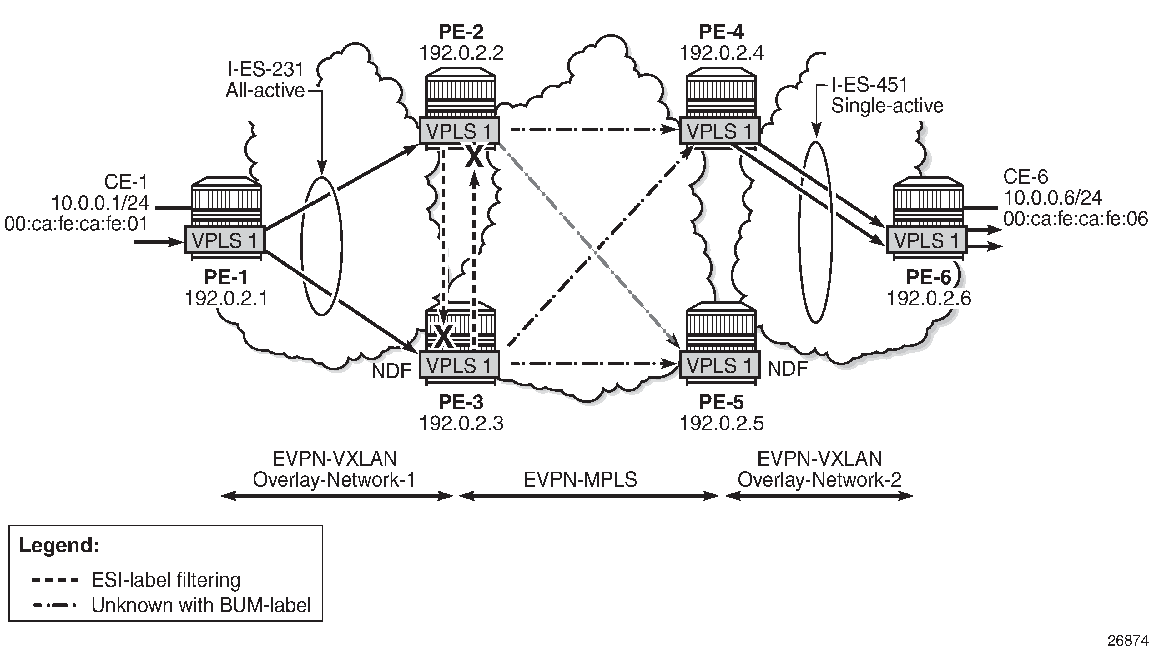
EVPN-MPLS interconnect for EVPN-VXLAN - BGP topology shows the topology and infrastructure configuration, which are the same as in chapter EVPN-MPLS Interconnect for EVPN-VXLAN VPLS Services. Read that chapter to see how the PEs are configured at port, IS-IS, and base BGP level.
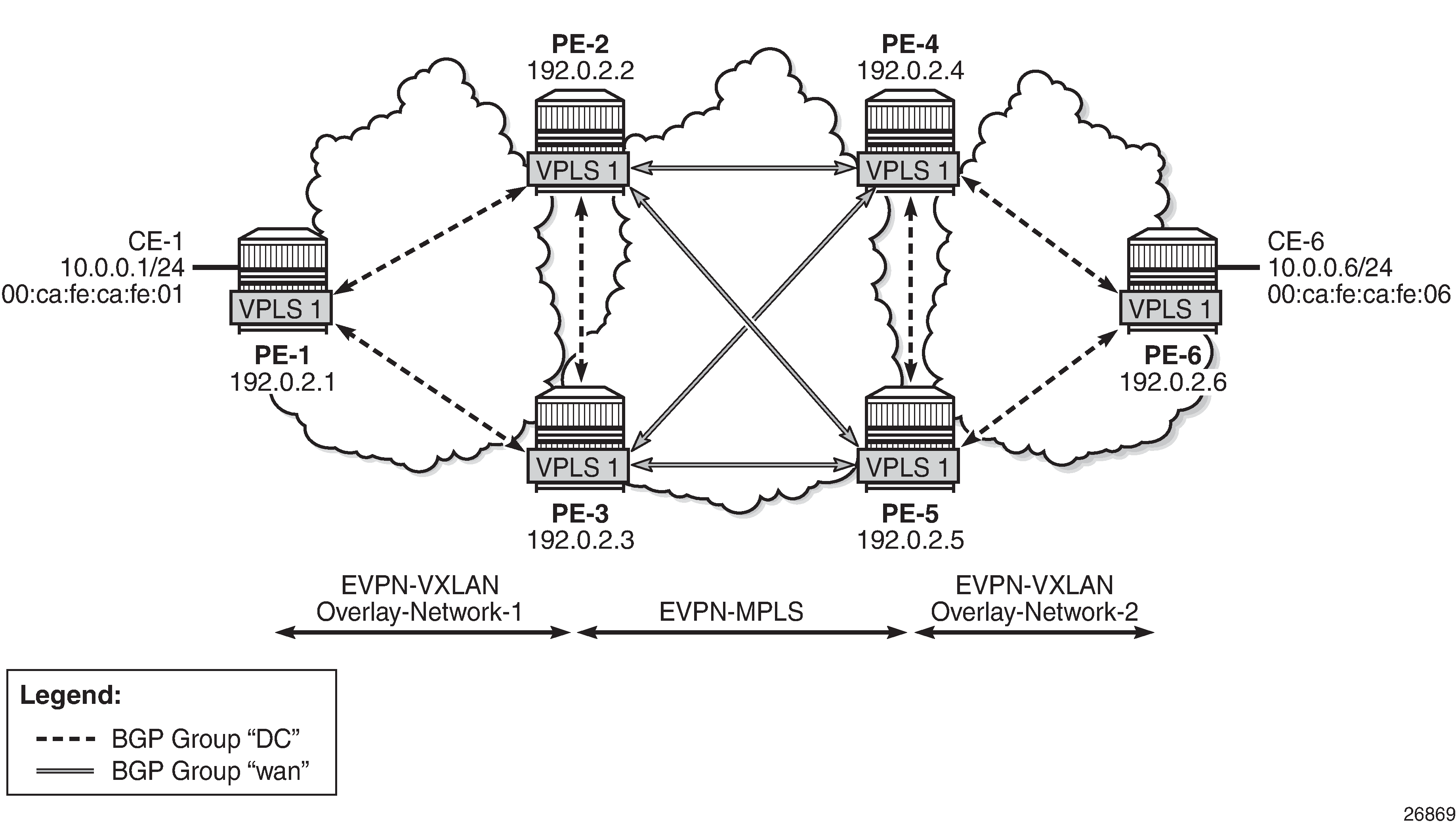
PE-1, PE-2, and PE-3 simulate a data center (DC), shown as Overlay-Network-1, where PE-2 and PE-3 are DCGWs. In the same way, PE-4, PE-5, and PE-6 simulate a remote DC, Overlay-Network-2. Inside each DC, EVPN-VXLAN is used and the two DCGW pairs are connected by EVPN-MPLS. CE-1 and CE-6 are end-to-end connected by EVPN without any VLAN or Pseudowire (PW) hand-off, maintaining all the EVPN advantages across the DC Interconnect (DCI) network.
Interconnect Ethernet Segment (I-ES) configuration
After the base infrastructure is configured (interfaces, IGP, LDP in the core, and BGP EVPN peering sessions, as per EVPN-MPLS interconnect for EVPN-VXLAN - BGP topology), two I-ESs configured on the DCGWs show the use of the Interconnect Ethernet Segments.
The I-ES "I-ES231" is configured on PE-2 and PE-3 as follows:
# on PE-2:
configure {
    service {
        system {
            bgp {
                evpn {
                    ethernet-segment "I-ES231" {
                        admin-state enable
                        type virtual
                        esi 00:23:23:23:23:23:23:00:00:01
                        multi-homing-mode all-active
                        df-election {
                            service-carving-mode manual
                            manual {
                                evi 101 {
                                    end 200
                                }
                                preference {
                                    mode non-revertive
                                    value 150
                                }
                            }
                        }
                        association {
                            network-interconnect-vxlan 1 {
                                virtual-ranges {
                                    service-id 1 {
                                        end 100
                                    }
                                    service-id 101 {
                                        end 200
                                    }
                                }
                            }
                        }
                    }
# on PE-3:
configure {
    service {
        system {
            bgp {
                evpn {
                    ethernet-segment "I-ES231" {
                        admin-state enable
                        type virtual
                        esi 00:23:23:23:23:23:23:00:00:01
                        multi-homing-mode all-active
                        df-election {
                            service-carving-mode manual
                            manual {
                                evi 101 {
                                    end 200
                                }
                                preference {
                                    mode non-revertive
                                    value 50
                                }
                            }
                        }
                        association {
                            network-interconnect-vxlan 1 {
                                virtual-ranges {
                                    service-id 1 {
                                        end 100
                                    }
                                    service-id 101 {
                                        end 200
                                    }
                                }
                            }
                        }
                    }
On PE-1 and PE-2, the preceding configuration associates I-ES "I-ES231" with the VXLAN instance 1 in services contained in the range VPLS 1 to 100 and 101 to 200. The I-ES is modeled as a virtual ES, where:
-
Two commands are needed within the ethernet-segment context: network-interconnect-vxlan and virtual-ranges service-id <svc-id> end <svc-id>.
-
The network-interconnect-vxlan command identifies the VXLAN instance associated with the virtual ES. Only value 1 is supported in SR OS Release 21.2.R2.
*[ex:/configure service system bgp evpn ethernet-segment "vES-23" association]
A:admin@PE-1# network-interconnect-vxlan ?

 [network-interconnect-vxlan-id] <number>
 <number>  - <1>

    Vxlan instance id multi-homed with this Ethernet segment entry.
The network-interconnect-vxlan command is rejected in non-virtual ESs:
*[ex:/configure service system bgp evpn ethernet-segment "ES-23" association] A:admin@PE-1# network-interconnect-vxlan 1 MINOR: MGMT_CORE #2203: configure service system bgp evpn ethernet-segment "ES-23" association network-interconnect-vxlan 1 - Invalid element - network-interconnect-vxlan allowed only on virtual ethernet-segments -
The service-id command associates the specific service range with the ES.
-
The other ES association options (port, lag, sdp, vc-id-range, dot1q, and qinq) cannot be combined with a network-interconnect-vxlan instance in an ES.
-
The rest of the ES configuration options are supported. The source-bmac-lsb is blocked because the I-ES cannot be associated with I-VPLS or PBB-Epipe services.
-
All the services with two BGP instances associate the VXLAN destinations and ingress VXLAN instance with the ES.
-
-
Multiple services (for example, 1 to 200 in the CLI above) can be associated with the same ES.
-
Up to eight service ranges per VXLAN instance can be configured. Ranges may overlap within the same ES (and not between different ESs). In this example, two non-overlapping ranges are configured to show the service range configuration, although a single range containing all the services could have been configured.
-
The service range may be configured before the service is, and it can be changed on the fly.
-
-
When the network-interconnect-vxlan I-ES is configured, the ES operational state depends exclusively on the ES admin state.
-
Because the I-ES is not associated with a physical port or SDP, when testing the non-revertive service-carving manual mode, an ethernet-segment admin-state disable/enable will result in the node sending its own administrative preference and "Do not preempt" (pref/DP) values, and taking over if pref/DP is higher than the current DF. This is because when the ES is enabled, the peer ES routes are not present at the EVPN application layer, so the PE will send its own admin pref/DP values. Therefore, for I-ESs, the non-revertive mode will only work for node failures. See the chapter for more information about the preference-based and non-revertive DF election modes.
-
-
There are no restrictions in the service-carving mode supported by I-ESs. In this example, preference-based service-carving is configured, but modes auto and (non-preference-based) manual are also supported.
-
As described in the Preference-based and Non-revertive EVPN DF Election chapter, the service-carving context is configured with an EVI range that will pick up the lowest preference value when electing a DF for the service, whereas the non-configured EVI services will pick up the highest value when electing a DF. In this example, this means that, of the services allowed in the I-ES, that is, 1 to 200, services 1 to 100 will elect the highest Preference PE as DF, whereas services 101 to 200 will elect the lowest Preference PE.
PE-4 and PE-5 are configured with I-ES "I-ES451". The configuration of I-ES451 is similar to that of I-ES231; only single-active mode is configured, instead of all-active mode.
# on PE-4:
configure {
    service {
        system {
            bgp {
                evpn {
                    ethernet-segment "I-ES451" {
                        admin-state enable
                        type virtual
                        esi 00:45:45:45:45:45:45:00:00:01
                        multi-homing-mode single-active
                        df-election {
                            service-carving-mode manual
                            manual {
                                evi 101 {
                                    end 200
                                }
                                preference {
                                    mode non-revertive
                                    value 150
                                }
                            }
                        }
                        association {
                            network-interconnect-vxlan 1 {
                                virtual-ranges {
                                    service-id 1 {
                                        end 100
                                    }
                                    service-id 101 {
                                        end 200
                                    }
                                }
                            }
                        }
                    }
                }
# on PE-5:
configure {
    service {
        system {
            bgp {
                evpn {
                    ethernet-segment "I-ES451" {
                        admin-state enable
                        type virtual
                        esi 00:45:45:45:45:45:45:00:00:01
                        multi-homing-mode single-active
                        df-election {
                            service-carving-mode manual
                            manual {
                                evi 101 {
                                    end 200
                                }
                                preference {
                                    mode non-revertive
                                    value 50
                                }
                            }
                        }
                        association {
                            network-interconnect-vxlan 1 {
                                virtual-ranges {
                                    service-id 1 {
                                        end 100
                                    }
                                    service-id 101 {
                                        end 200
                                    }
                                }
                            }
                        }
                    }
                }
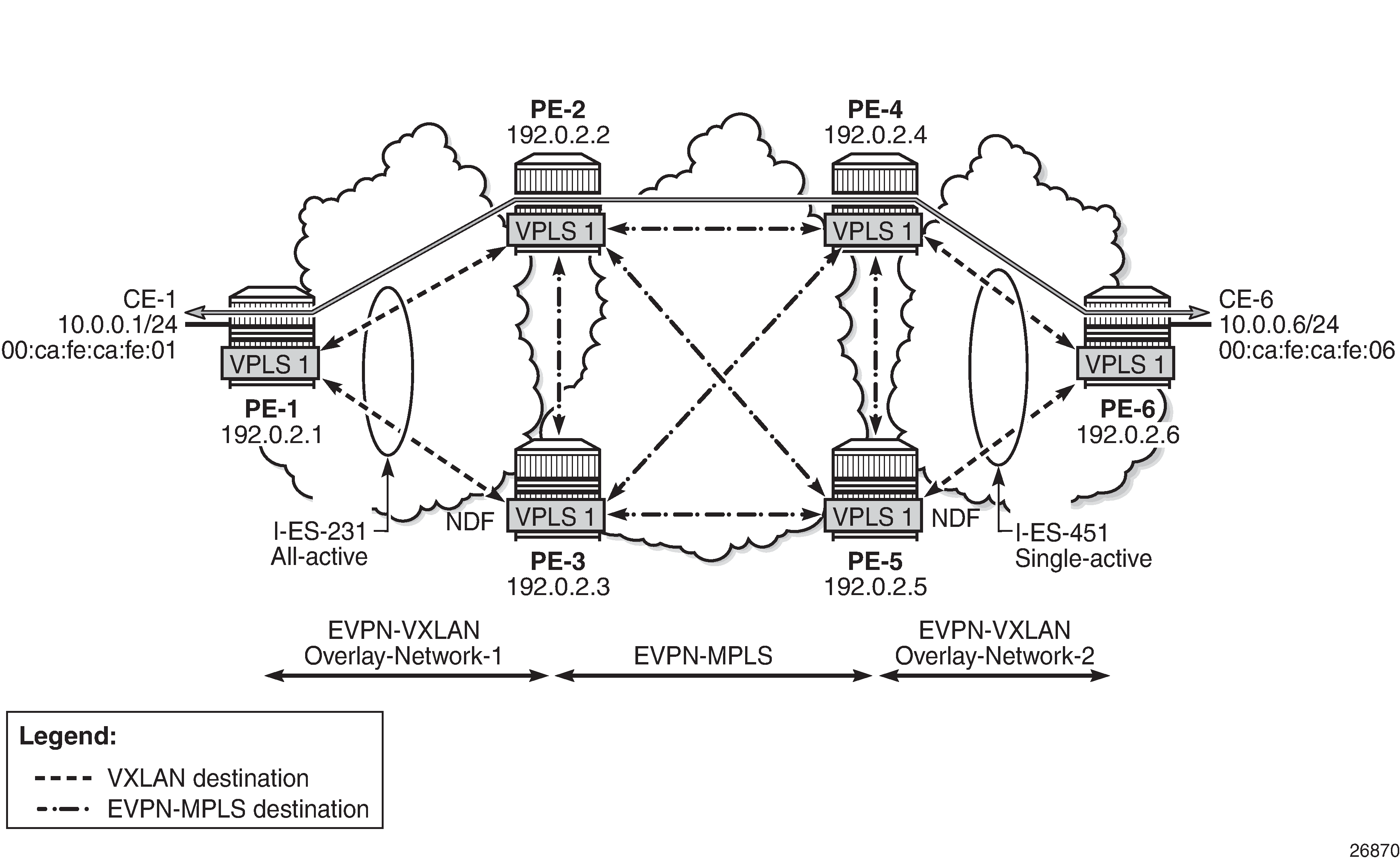
In this example, VPLS 1 will be configured and associated with the preceding I-ESs. VPLS service and association with I-ESs shows an example of VPLS 1 and how it is associated with the I-ESs.
The configuration of VPLS 1 for PE-1, PE-2, and PE-3 is as follows. VPLS 101 is also configured in all the PEs in a similar way as VPLS 1, but not shown here. Also, the VPLS 1 configuration on the rest of the PEs is equivalent to the one in PE-1, PE-2, and PE-3, as follows:
# on PE-1:
configure {
    service {
        vpls "VPLS 1" {
            admin-state enable
            service-id 1
            customer "1"
            vxlan {
                instance 1 {
                    vni 1
                }
            }
            bgp 1 {
            }
            bgp-evpn {
                evi 1
                vxlan 1 {
                    admin-state enable
                    vxlan-instance 1
                }
            }
            sap 1/2/1:1 {
            }
        }
# on PE-2:
configure {
    service {
        vpls "VPLS 1" {
            admin-state enable
            service-id 1
            customer "1"
            vxlan {
                instance 1 {
                    vni 1
                }
            }
            bgp 1 {
                route-distinguisher "192.0.2.2:1"
            }
            bgp 2 {
                route-distinguisher "192.0.2.2:2"
            }
            bgp-evpn {
                evi 1
                vxlan 1 {
                    admin-state enable
                    vxlan-instance 1
                }
                mpls 2 {
                    admin-state enable
                    ingress-replication-bum-label true
                    ecmp 2
                    auto-bind-tunnel {
                        resolution any
                    }
                }
            }
        }
# on PE-3:
configure {
    service {
        vpls "VPLS 1" {
            admin-state enable
            service-id 1
            customer "1"
            vxlan {
                instance 1 {
                    vni 1
                }
            }
            bgp 1 {
                route-distinguisher "192.0.2.3:1"
            }
            bgp 2 {
                route-distinguisher "192.0.2.3:2"
            }
            bgp-evpn {
                evi 1
                vxlan 1 {
                    admin-state enable
                    vxlan-instance 1
                }
                mpls 2 {
                    admin-state enable
                    ingress-replication-bum-label true
                    ecmp 2
                    auto-bind-tunnel {
                        resolution any
                    }
                }
            }
        }
As in the case of any other ESs, the association of instance and service is based on the ES configuration and there is no extra configuration required at the service level to make that association. The existing show commands that are used to check the status of the ES can be used to check the I-ESs. For example, on I-ES231:
[/]
A:admin@PE-2# show service system bgp-evpn ethernet-segment name "I-ES231" all

===============================================================================
Service Ethernet Segment
===============================================================================
Name                    : I-ES231
Eth Seg Type            : Virtual
Admin State             : Enabled            Oper State         : Up
ESI                     : 00:23:23:23:23:23:23:00:00:01
Multi-homing            : allActive          Oper Multi-homing  : allActive
ES SHG Label            : 524278
Source BMAC LSB         : <none>
VXLAN Instance Id       : 1
ES Activation Timer     : 3 secs (default)
Oper Group              : (Not Specified)
Svc Carving             : manual             Oper Svc Carving   : manual
Cfg Range Type          : lowest-pref

-------------------------------------------------------------------------------
DF Pref Election Information
-------------------------------------------------------------------------------
Preference     Preference     Last Admin Change        Oper Pref      Do No
Mode           Value                                   Value          Preempt
-------------------------------------------------------------------------------
non-revertive  150            05/03/2021 13:01:53      150            Enabled
-------------------------------------------------------------------------------

-------------------------------------------------------------------------------
EVI Ranges
-------------------------------------------------------------------------------
From                                    To
-------------------------------------------------------------------------------
101                                     200
-------------------------------------------------------------------------------
ISID Ranges: <none>
===============================================================================

===============================================================================
EVI Information
===============================================================================
EVI                 SvcId               Actv Timer Rem      DF
-------------------------------------------------------------------------------
1                   1                   0                   yes
101                 101                 0                   no
-------------------------------------------------------------------------------
Number of entries: 2
===============================================================================

-------------------------------------------------------------------------------
DF Candidate list
-------------------------------------------------------------------------------
EVI                                     DF Address
-------------------------------------------------------------------------------
1                                       192.0.2.2
1                                       192.0.2.3
101                                     192.0.2.2
101                                     192.0.2.3
-------------------------------------------------------------------------------
Number of entries: 4
-------------------------------------------------------------------------------
-------------------------------------------------------------------------------
---snip---

===============================================================================
Vxlan Instance Service Ranges
===============================================================================
Svc Range Start          Svc Range End            Last Changed
-------------------------------------------------------------------------------
1                        100                      05/03/2021 13:01:53
101                      200                      05/03/2021 13:01:53
-------------------------------------------------------------------------------
Number of Entries: 2
===============================================================================
The show service id 1 vxlan instance 1 oper-flags command shows the status of a VXLAN instance in the service. A service VXLAN instance will raise the oper-flag MhStandby (multi-homing standby) due to any of the following reasons:
-
The PE is (single-active) non-Designated Forwarder (NDF) for that I-ES.
-
The VXLAN service is added to the I-ES and either the ES is disabled or bgp-evpn>mpls is disabled in all the services included in the ES.
For example, because PE-5 is an NDF in I-ES451, the MhStandby flag will show "true":
[/]
A:admin@PE-5# show service id 1 vxlan instance 1 oper-flags

===============================================================================
VPLS VXLAN oper flags
===============================================================================
MhStandby                              : true
===============================================================================
EVPN route handling in dual BGP-instance VPLSs with I-ES
The configuration of I-ESs on DCGWs with two BGP instances has the following impact on the advertisement and process of the BGP-EVPN routes:
-
EVPN MAC/IP routes:
-
MAC/IP routes received on the EVPN-MPLS BGP instance will be re-advertised to the EVPN-VXLAN BGP instance with the ESI set to zero in SR OS Release 21.2.R2.
-
EVPN-VXLAN PE/NVEs (Network Virtual Edge devices) in the DC will receive the same MAC address from two (or more) different MAC/IP routes from the DCGWs. The EVPN-VXLAN PE/NVEs will perform regular EVPN MAC/IP route selection.
-
MAC/IP routes received on the EVPN-VXLAN BGP instance will be re-advertised to the EVPN-MPLS BGP instance with the configured non-zero I-ESI value, assuming the VXLAN instance is not in the MhStandby operational state. MAC/IP routes received on the EVPN-VXLAN BGP instance will be dropped if the VXLAN instance is in the MhStandby state.
-
EVPN-MPLS PEs in the WAN will receive the same MAC address from two (or more) DCGWs, set with the same ESI. EVPN-MPLS PEs will perform regular aliasing and backup functions.
-
-
ES routes are exchanged for the I-ES. They should be sent only to the MPLS network and not to the VXLAN side. This can be achieved by using router policies. In any case, because ES routes use an ES-import route-target extended community, they should not be imported by VXLAN PEs.
-
Auto-discover per ES (AD per-ES) and AD per-EVI routes are also advertised for the I-ES. They should be sent only to the MPLS network and not to the VXLAN network. As for ES routes, router policies can be used to prevent AD routes being sent to VXLAN peers.
Required BGP policies to avoid control plane loops
Usually, the use of router policies is required when I-ESs are used for redundancy, to avoid control plane loops with MAC/IP routes. The control plane loops to be avoided are as follows:
-
Loops created by remote MAC addresses (learned on remote PE SAPs):
-
Remote EVPN-MPLS MAC/IP routes are re-advertised into EVPN-VXLAN with a Site of Origin (SOO) extended community (added by a BGP peer or vsi-export policy) identifying the DCGW pair. The other DCGW in the pair will drop EVPN-VXLAN MAC routes tagged with the self SOO. Router policies to add SOO and drop routes received with self SOO are needed.
-
Also, when remote EVPN-VXLAN MAC/IP routes are re-advertised into EVPN-MPLS, the DCGWs will automatically drop EVPN-MPLS MAC/IP routes received with their own non-zero I-ESI. No router policies are needed for this.
-
-
Loops created by local SAP MAC addresses:
-
Local SAP MACs are learned and MAC/IP routes are advertised into both BGP instances. The MAC/IP routes advertised in the EVPN-VXLAN instance will be dropped by the peer based on the SOO router policies, as described in (1a) above, and DCGW local MACs will always be learned over the EVPN-MPLS destinations between the DCGWs.
-
Because only EVPN-MPLS destinations exist between the DCGWs, EVPN-VXLAN MAC/IP and IMET routes exchanged between the DCGWs will be discarded and EVPN-VXLAN destinations will not be created between them.
-
As an example, the following BGP peer policies on PE-2 and PE-3 achieve the goals described above (similar policies would be configured on PE-4 and PE-5) and summarized as follows:
-
Avoid sending service VXLAN routes to MPLS peers, and service MPLS routes to VXLAN peers.
-
Avoid sending AD and ES routes to VXLAN peers.
-
Add SOO to VXLAN routes to be sent to the ES peer.
-
Drop VXLAN routes received from the ES peer.
# on PE-2, PE-3:
configure {
    policy-options {
        community "SOO-DCGW-23" {
            member "origin:64500:23" { }
        }
        community "mpls" {
            member "bgp-tunnel-encap:MPLS" { }
        }
        community "vxlan" {
            member "bgp-tunnel-encap:VXLAN" { }
        }
The following policy prevents the router from sending service VXLAN routes to MPLS peers:
        policy-statement "allow only mpls" {
            entry 10 {
                from {
                    family [evpn]
                    community {
                        name "vxlan"
                    }
                }
                action {
                    action-type reject
                }
            }
        }
The following policy makes sure the router exports only routes that include the VXLAN encapsulation:
        policy-statement "allow only vxlan" {
            entry 10 {
                from {
                    family [evpn]
                    community {
                        name "vxlan"
                    }
                }
                action {
                    action-type accept
                }
            }
            default-action {
                action-type reject
            }
        }
The following import policy avoids importing routes with self SOO:
        policy-statement "drop SOO-DCGW-23" {
            entry 10 {
                from {
                    family [evpn]
                    community {
                        name "SOO-DCGW-23"
                    }
                }
                action {
                    action-type reject
                }
            }
        }
The following export policy adds SOO but only to VXLAN routes. This allows the peer to drop routes based on the SOO, without affecting the MPLS routes.
        policy-statement "add SOO to vxlan routes" {
            entry 10 {
                from {
                    family [evpn]
                    community {
                        name "vxlan"
                    }
                }
                action {
                    action-type accept
                    community {
                        add ["SOO-DCGW-23"]
                    }
                }
            }
            default-action {
                action-type accept
            }
        }
The BGP configuration for PE-2 and PE-3 is as follows:
# on PE-2:
configure {
    router "Base" {
        autonomous-system 64500
        router-id 192.0.2.2
        bgp {
            vpn-apply-export true
            vpn-apply-import true
            rapid-withdrawal true
            family {
                ipv4 false
                evpn true
            }
            rapid-update {
                evpn true
            }
            group "dc" {
                type internal
                export {
                    policy ["allow only vxlan"]
                }
            }
            group "wan" {
                type internal
                export {
                    policy ["allow only mpls"]
                }
            }
            neighbor "192.0.2.1" {
                group "dc"
            }
            neighbor "192.0.2.3" {
                group "dc"
                import {
                    policy ["drop SOO-DCGW-23"]
                }
                export {
                    policy ["add SOO to vxlan routes"]
                }
            }
            neighbor "192.0.2.4" {
                group "wan"
            }
            neighbor "192.0.2.5" {
                group "wan"
            }
# on PE-3:
configure {
    router "Base" {
        autonomous-system 64500
        router-id 192.0.2.3
        bgp {
            vpn-apply-export true
            vpn-apply-import true
            rapid-withdrawal true
            family {
                ipv4 false
                evpn true
            }
            rapid-update {
                evpn true
            }
            group "dc" {
                type internal
                export {
                    policy ["allow only vxlan"]
                }
            }
            group "wan" {
                type internal
                export {
                    policy ["allow only mpls"]
                }
            }
            neighbor "192.0.2.1" {
                group "dc"
            }
            neighbor "192.0.2.2" {
                group "dc"
                import {
                    policy ["drop SOO-DCGW-23"]
                }
                export {
                    policy ["add SOO to vxlan routes"]
                }
            }
            neighbor "192.0.2.4" {
                group "wan"
            }
            neighbor "192.0.2.5" {
                group "wan"
            }
Single-active multi-homing operation
When the I-ES is configured as single-active and admin-state enabled (assuming at least one service is associated), the DCGWs will send ES and AD routes as usual for any ES, and run DF election based on the ES routes, with the candidate list being pruned by the AD routes.
In VPLS service and association with I-ESs, PE-4 and PE-5 are configured with I-ES451, which is a single-active ES. The NDF for a service (PE-5 for VPLS 1 in the example) will perform the following tasks:
-
The VXLAN instance on the NDF will enter the MhStandby state and will block ingress and egress traffic on the VXLAN destinations associated with the I-ES.
[/] A:admin@PE-5# show service id 1 vxlan instance 1 oper-flags =============================================================================== VPLS VXLAN oper flags =============================================================================== MhStandby : true =============================================================================== -
MAC/IP routes and FDB process:
-
Advertised MAC/IP routes that are associated with the VXLAN instance are withdrawn.
-
Advertised MAC/IP routes corresponding to local SAP MAC addresses or EVPN-MPLS binding MAC addresses are withdrawn if they were advertised to the EVPN-VXLAN instance.
-
Received MAC/IP routes associated with the VXLAN instance are not installed in FDB. The MAC routes will show as "used" in the show router bgp routes evpn mac commands; however, only the MAC addresses received from MPLS (in particular from the ES peer) will be programmed. As an example, the following CLI output shows how MAC address 00:ca:fe:ca:fe:06 is learned on PE-4 (DF) and associated with the VXLAN destination to PE-6, whereas the MAC address is installed associated with an MPLS destination (remote ES) on PE-5 (NDF).
[/]
A:admin@PE-4# show service id 1 fdb detail

===============================================================================
Forwarding Database, Service 1
===============================================================================
ServId     MAC               Source-Identifier       Type     Last Change
            Transport:Tnl-Id                         Age
-------------------------------------------------------------------------------
1          00:ca:fe:ca:fe:01 eES:                    Evpn     05/03/21 13:10:58
                             00:23:23:23:23:23:23:00:00:01
1          00:ca:fe:ca:fe:06 vxlan-1:                Evpn     05/03/21 13:10:58
                             192.0.2.6:1
-------------------------------------------------------------------------------
No. of MAC Entries: 2
-------------------------------------------------------------------------------
Legend:  L=Learned O=Oam P=Protected-MAC C=Conditional S=Static Lf=Leaf
===============================================================================
[/] A:admin@PE-5# show service id 1 fdb detail =============================================================================== Forwarding Database, Service 1 =============================================================================== ServId MAC Source-Identifier Type Last Change Transport:Tnl-Id Age ------------------------------------------------------------------------------- 1 00:ca:fe:ca:fe:01 eES: Evpn 05/03/21 13:10:58 00:23:23:23:23:23:23:00:00:01 1 00:ca:fe:ca:fe:06 eES: Evpn 05/03/21 13:10:58 00:45:45:45:45:45:45:00:00:01 ------------------------------------------------------------------------------- No. of MAC Entries: 2 ------------------------------------------------------------------------------- Legend: L=Learned O=Oam P=Protected-MAC C=Conditional S=Static Lf=Leaf ===============================================================================
-
-
Inclusive Multicast Ethernet Tag (IMET) routes process:
-
IMET-Assisted Replication with replicator role (IMET-AR-R) routes are withdrawn if the VXLAN instance enters the MhStandby state. Only the DF will advertise the IMET-AR-R routes. For more information on AR, see chapter ‟Layer 2 Multicast Optimization for EVPN-VXLAN - Assisted Replication” in the Layer 2 Services and EVPN section of the 7450 ESS, 7750 SR, and 7950 XRS Advanced Configuration Guide - Part II.
-
IMET-Ingress Replication advertisements (IMET-IR) routes, in case of NDF (or the MhStandby state), are controlled by the config>service>vpls>bgp-evpn>vxlan# send-incl-mcast-ir-on-ndf command.
-
By default, the command is enabled and the router will advertise IMET-IR routes even if the PE is NDF (MhStandby). This will attract BUM traffic (even if the NDF ends up dropping it); however, attracting BUM traffic will also speed up convergence in case of DF switchover. The command works for single-active and all-active.
-
If disabled, the router will withdraw the IMET-IR routes when the PE is NDF and will not attract BUM traffic.
-
-
In spite of not sending BUM or unicast traffic, the NDF for a service still creates the VXLAN bindings; however, they are not associated with any MAC addresses and they are flagged as non-multicast capable, or "-" in the Mcast column of the following command:
[/]
A:admin@PE-5# show service id 1 vxlan destinations

===============================================================================
Egress VTEP, VNI
===============================================================================
Instance    VTEP Address                            Egress VNI  EvpnStatic Num
 Mcast       Oper State                              L2 PBR     SupBcasDom MACs
-------------------------------------------------------------------------------
1           192.0.2.6                               1           evpn       0
 -           Up                                      No          No
-------------------------------------------------------------------------------
Number of Egress VTEP, VNI : 1
-------------------------------------------------------------------------------
===============================================================================

===============================================================================
BGP EVPN-VXLAN Ethernet Segment Dest
===============================================================================
Instance  Eth SegId                       Num. Macs     Last Change
-------------------------------------------------------------------------------
No Matching Entries
===============================================================================
The I-ES DF PE for the service (PE-4) will continue advertising IMET and MAC/IP routes for the associated VXLAN instance. Forwarding will also happen as usual on the DF VXLAN bindings. When the DF PE receives BUM traffic from VXLAN, it will send it, adding the egress ESI label if needed.
All-active multi-homing operation
The same considerations as in single-active for ES and AD routes and DF election apply to all-active multi-homing. In VPLS service and association with I-ESs, PE-2 and PE-3 are configured with I-ES231, which is an all-active ES. The NDF PE for a service (PE-3 for VPLS 1, in the example) will show the following behavior:
-
The VXLAN instance on the NDF will not enter the MhStandby state because it will still forward unicast traffic:
[/] A:admin@PE-3# show service id 1 vxlan instance 1 oper-flags =============================================================================== VPLS VXLAN oper flags =============================================================================== MhStandby : false =============================================================================== -
MAC/IP routes and FDB process: MAC/IP routes are received, installed, and advertised as in the DF router.
-
IMET routes process:
-
As in the single-active case, IMET-AR-R routes are withdrawn on the NDF. Only the DF will advertise the IMET-AR-R routes.
-
Also, as in the single-active case, IMET-IR advertisement from the NDF will be controlled by the config>service>vpls>bgp-evpn>vxlan# send-incl-mcast-ir-on-ndf command. Advertising the IMET-IR route from the NDF will attract BUM traffic from the VXLAN PEs to the NDF, even though the unknown unicast traffic will be forwarded only when it is safe to do so. See section All-active multi-homing and unknown unicast forwarding on the NDF for more information about unknown unicast forwarding.
-
Contrary to the behavior in single-active multi-homing, in all-active, the NDF will forward unknown unicast to the VXLAN PEs as usual, but block broadcast and multicast in the upstream and downstream direction. In our example, the NDF for VPLS 1 (PE-3) will show the VXLAN destinations created as "U" (Unknown unicast) in the Mcast column of the show service id 1 vxlan command, as follows:
[/]
A:admin@PE-3# show service id 1 vxlan destinations

===============================================================================
Egress VTEP, VNI
===============================================================================
Instance    VTEP Address                            Egress VNI  EvpnStatic Num
 Mcast       Oper State                              L2 PBR     SupBcasDom MACs
-------------------------------------------------------------------------------
1           192.0.2.1                               1           evpn       1
 U           Up                                      No          No
-------------------------------------------------------------------------------
Number of Egress VTEP, VNI : 1
-------------------------------------------------------------------------------
===============================================================================

===============================================================================
BGP EVPN-VXLAN Ethernet Segment Dest
===============================================================================
Instance  Eth SegId                       Num. Macs     Last Change
-------------------------------------------------------------------------------
No Matching Entries
===============================================================================
All-active multi-homing and unknown unicast forwarding on the NDF
The unknown unicast traffic will be transmitted on the (all-active multi-homing) NDF in the upstream and downstream directions only in those cases where there is no risk of packet duplication. The router considers there is no risk when transmitting an unknown unicast packet on the NDF if:
-
Unknown unicast packet arrives without an ESI label.
-
Unknown unicast packet arrives without a BUM label (label advertised by an IMET route as opposed to a MAC/IP route).
-
Unknown unicast packet passes a MAC Source Address (MAC SA) suppression (MAC SA lookup does not yield an entry associated with the I-ES).
The following examples show how unknown unicast traffic is handled in all-active I-ESs.
All-active multi-homing and unknown unicast example 1 shows an example with two DCGWs where (all-active) I-ES-1 is defined.
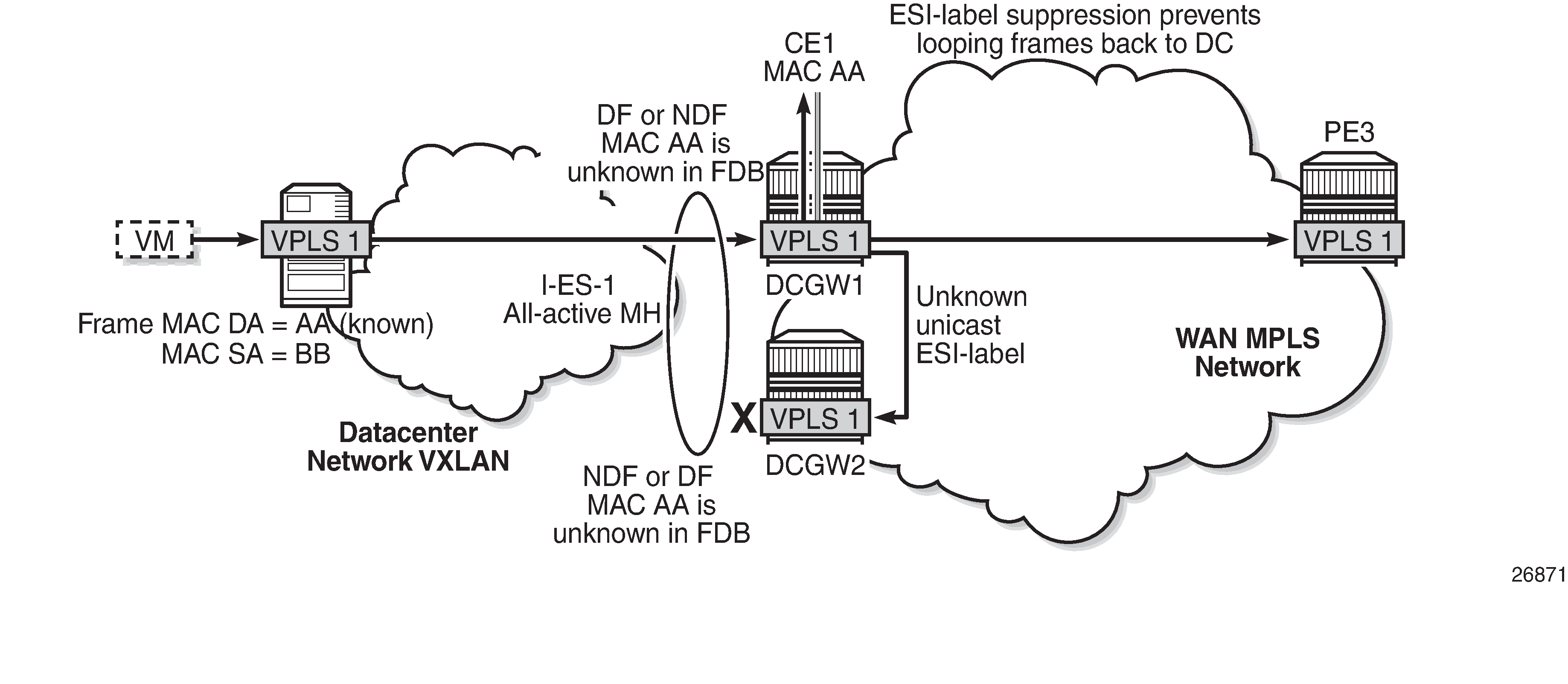
The VXLAN PE/NVE transmits known unicast traffic, whereas DCGW1 has not learned the MAC address yet. Regardless of the DCGW1 being DF or NDF, it will accept unknown unicast and will flood to local SAPs and EVPN destinations. When sending to DCGW2, the router will send the ESI label identifying the I-ES. DCGW2 will not send unknown traffic back to the DC due to the ESI-label suppression on the I-ES.
All-active multi-homing and unknown unicast example 2 shows a similar example where the VXLAN node sends known unicast with MAC Destination Address (MAC DA) "AA" to DCGW2.
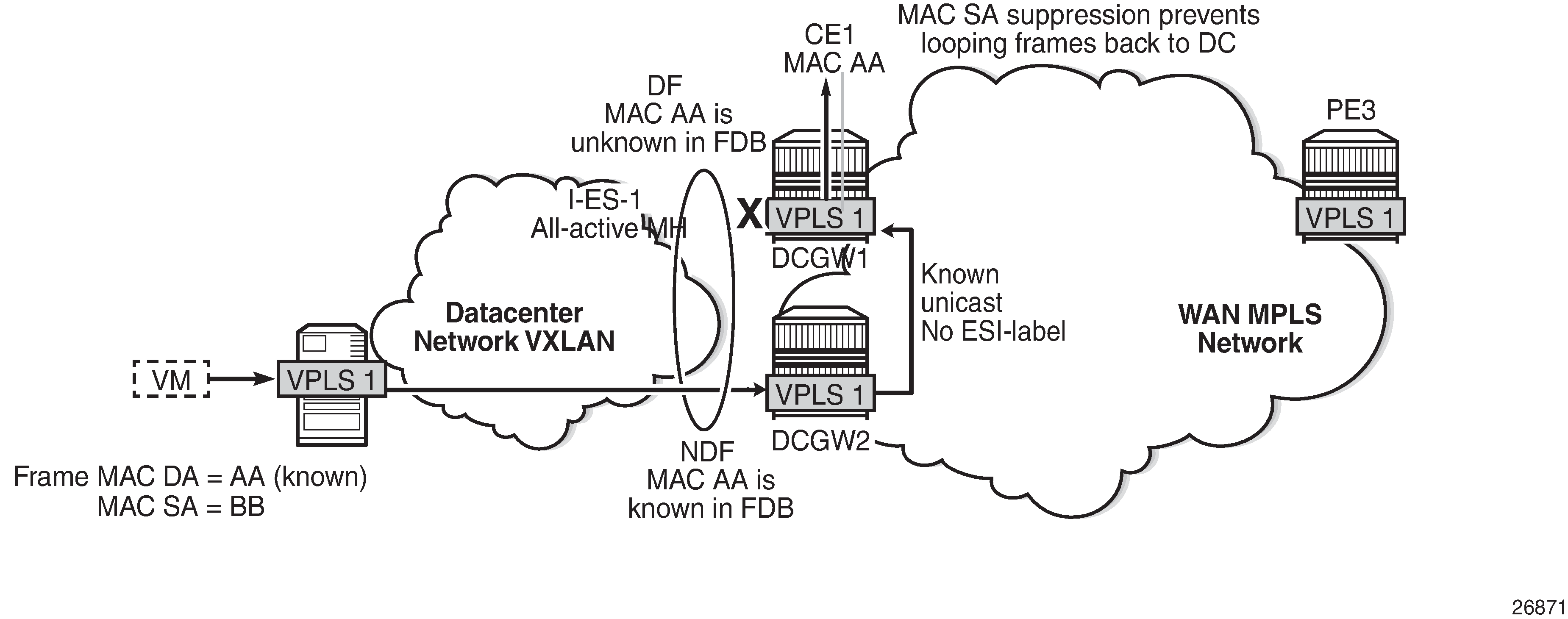
DCGW2 does a MAC lookup and sends the frame as known unicast to DCGW1 via the EVPN-MPLS destination. However, MAC AA is unknown in DCGW1 for some reason (such as FDB limit exceeded, SAP failure, and so on). In this case, DCGW1 will flood the frame to CE1 and not to the VXLAN network. Even though the frame is not coming with an ESI label, the DCGW1 router does a MAC SA suppression and will not send unknown unicast frames to the I-ES. MAC SA suppression means that the router will do a MAC SA lookup on the FDB and will suppress the flooding to the I-ES if the MAC SA is learned on the I-ES (as in All-active multi-homing and unknown unicast example 2).
All-active multi-homing and unknown unicast example 3 shows an example in which the NDF forwards "no-risk" unknown unicast traffic to avoid black-holes.
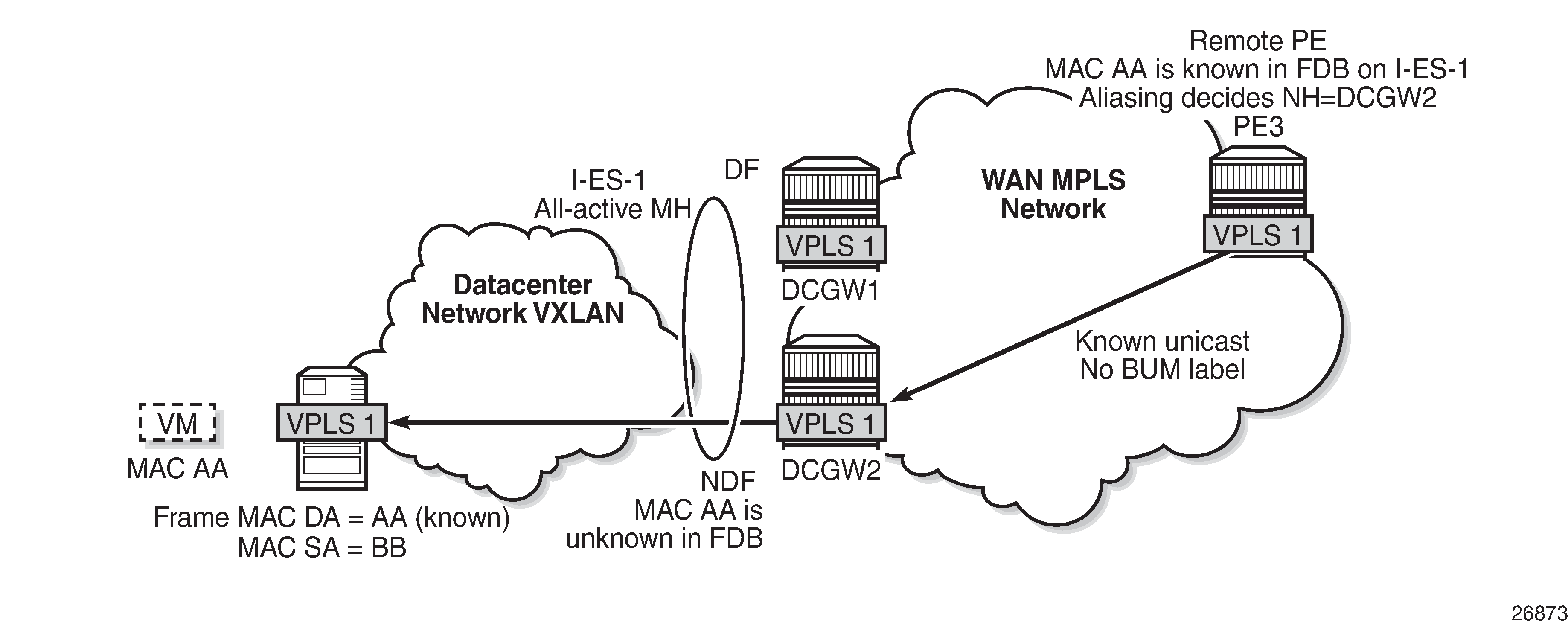
PE3 receives unicast traffic with MAC DA = AA. The MAC address is known in the FDB and associated with I-ES-1; therefore, because PE3 is configured to do aliasing to DCGW1 and DCGW2 (bgp-evpn>mpls# ecmp 2), a packet hash determines that it has to be sent to DCGW2 (NDF). The packet arrives at DCGW2 with a unicast label. DCGW2 does a lookup and MAC AA is unknown for some reason (such as FDB limit exceeded, MAC not learned yet, and so on). In this case, DCGW2 will forward the packet to the I-ES VXLAN bindings, even if it is NDF. This behavior avoids black-hole periods in the network for unicast traffic.
Finally, in some cases, the unknown unicast forwarding behavior on the NDF may cause some transient packet duplication that can be avoided by configuring the send-incl-mcast-ir-on-ndf command. The following example shows the use of this command to avoid transient packet duplication. All-active multi-homing and send-incl-mcast-ir-on-ndf true shows how transient packet duplication may occur with the default setting (send-incl-mcast-ir-on-ndf true).
Transient packet duplication may occur when sending unknown unicast from CE-1 to CE-6, if send-incl-mcast-ir-on-ndf true is configured in PE-3 and PE-2. To show this, we clear the FDBs in all the PEs in the example as well as the ARP caches on the CEs.
The following command is executed in all the PEs and CEs:
[/]
A:admin@PE-1# clear service id 1 fdb all

[/]
A:admin@PE-1# show service id 1 fdb detail

===============================================================================
Forwarding Database, Service 1
===============================================================================
ServId     MAC               Source-Identifier       Type     Last Change
            Transport:Tnl-Id                         Age
-------------------------------------------------------------------------------
No Matching Entries
===============================================================================
The following command clears the ARP table of the VPRN instance (defined in PE-1 using a loop) simulating CE-1:
[/]
A:admin@PE-1# clear router 300 arp all

[/]
A:admin@PE-1# show router 300 arp

===============================================================================
ARP Table (Service: 300)
===============================================================================
IP Address      MAC Address       Expiry    Type   Interface
-------------------------------------------------------------------------------
10.0.0.1        00:ca:fe:ca:fe:01 00h00m00s Oth[I] local
-------------------------------------------------------------------------------
No. of ARP Entries: 1
===============================================================================
When ICMP traffic is sent from CE-1 to CE-6, a duplicate entry occurs on CE-1:
[/]
A:admin@PE-1# ping 10.0.0.6 router-instance "VPRN 300"
PING 10.0.0.6 56 data bytes
64 bytes from 10.0.0.6: icmp_seq=1 ttl=64 time=13.2ms.
64 bytes from 10.0.0.6: icmp_seq=1 ttl=64, duplicate.
64 bytes from 10.0.0.6: icmp_seq=2 ttl=64 time=5.27ms.
64 bytes from 10.0.0.6: icmp_seq=3 ttl=64 time=5.25ms.
64 bytes from 10.0.0.6: icmp_seq=4 ttl=64 time=4.73ms.
64 bytes from 10.0.0.6: icmp_seq=5 ttl=64 time=4.80ms.

---- 10.0.0.6 PING Statistics ----
5 packets transmitted, 5 packets received, 1 duplicate
round-trip min = 4.73ms, avg = 6.66ms, max = 13.2ms, stddev = 3.29ms
This duplicate entry occurs because the packet gets to CE-6 twice and CE-6 sends two unicast ICMP reply messages back. From the CE-1 packet walkthrough:
-
PE-1 floods the packet to PE-2 and PE-3 because the CE-6 MAC DA is unknown and it has VXLAN multicast destinations to them.
-
PE-2 floods the unknown unicast packet to all the remote PEs because it is DF for I-ES231. PE-2 will add an ESI label when sending to PE-3, and a BUM label when sending to all of them.
-
PE-3 is NDF for I-ES231, but it floods the packet because the I-ES is all-active and the unknown unicast packet is considered low risk. The packet arrives with no ESI label, no BUM label (in VXLAN, VNIs are the same for unicast and BUM), and the MAC SA suppression passes because the packet is coming from the I-ES and not from MPLS. PE-3 uses a BUM label when flooding the packet and an ESI label when sending to PE-2.
-
PE-4 receives two unknown unicast packets and forwards both to PE-6.
-
PE-5 does not forward because it is NDF. This is true regardless of the I-ES being single-active or all-active (if all-active, the packet will not be forwarded because it arrives with a BUM label).
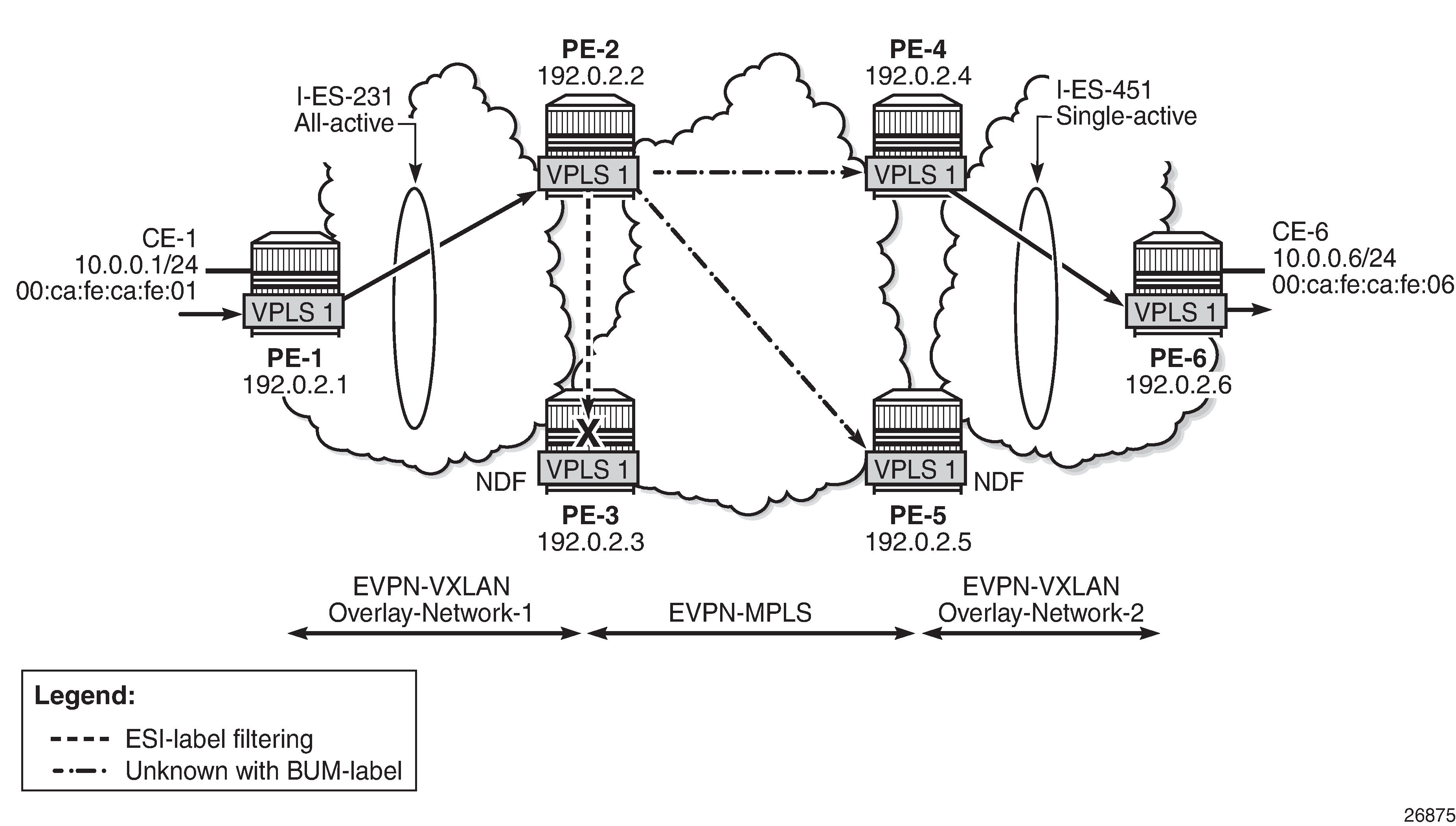
This packet duplication situation is transient and it will stop as soon as the two MAC addresses are learned on the PEs. However, if needed, this situation can be avoided by configuring send-incl-mcast-ir-on-ndf false:
# on PE-2, PE-3:
configure {
    service {
        vpls "VPLS 1" {
            bgp-evpn {
                vxlan 1 {
                    send-incl-mcast-ir-on-ndf false
This command will make the NDF (PE-3) withdraw the IMET-IR route; therefore, PE-1 will only flood unknown unicast packets to the DF (PE-2). The following IMET-IR routes are received on PE-1: one route sent by DF PE-2 for VPLS 1 and two routes for VPLS 101.
[/]
A:admin@PE-1# show router bgp routes evpn incl-mcast
===============================================================================
 BGP Router ID:192.0.2.1        AS:64500       Local AS:64500
===============================================================================
 Legend -
 Status codes  : u - used, s - suppressed, h - history, d - decayed, * - valid
                 l - leaked, x - stale, > - best, b - backup, p - purge
 Origin codes  : i - IGP, e - EGP, ? - incomplete

===============================================================================
BGP EVPN Inclusive-Mcast Routes
===============================================================================
Flag  Route Dist.         OrigAddr
      Tag                 NextHop
-------------------------------------------------------------------------------
u*>i  192.0.2.2:1         192.0.2.2
      0                   192.0.2.2

u*>i  192.0.2.2:101       192.0.2.2
      0                   192.0.2.2

u*>i  192.0.2.3:101       192.0.2.3
      0                   192.0.2.3

-------------------------------------------------------------------------------
Routes : 3
===============================================================================
If a DF switchover occurs in the I-ES, the new DF would advertise the IMET-IR route and the new NDF would withdraw it.
After clearing FDBs and ARP caches again, the test is repeated with no packet duplication. All-active multi-homing and send-incl-mcast-ir-on-ndf false shows how PE-1 does not send unknown unicast to PE-3 (NDF) anymore and, therefore, there is no duplication.
[/]
A:admin@PE-1# ping 10.0.0.6 router-instance "VPRN 300"
PING 10.0.0.6 56 data bytes
64 bytes from 10.0.0.6: icmp_seq=1 ttl=64 time=15.3ms.
64 bytes from 10.0.0.6: icmp_seq=2 ttl=64 time=5.32ms.
64 bytes from 10.0.0.6: icmp_seq=3 ttl=64 time=5.33ms.
64 bytes from 10.0.0.6: icmp_seq=4 ttl=64 time=5.44ms.
64 bytes from 10.0.0.6: icmp_seq=5 ttl=64 time=4.98ms.

---- 10.0.0.6 PING Statistics ----
5 packets transmitted, 5 packets received, 0.00% packet loss
round-trip min = 4.98ms, avg = 7.26ms, max = 15.3ms, stddev = 4.00ms
Local SAPs and provider tunnels along with I-ES
As described in the Overview section, the main advantages of the I-ES solution over the anycast redundant solution for dual BGP-instance services are the support of local SAPs and P2MP mLDP trees without packet duplication. This section shows the configuration of local SAPs and provider tunnels along with I-ES in VPLS services. The local SAPs can, at the same time, belong to an ES or a vES.
As an example, VPLS 1 on PE-2 is reconfigured as follows (similar configuration on PE-3, with provider tunnel also configured on PE-4 and PE-5):
# on PE-2:
configure {
    service {
        vpls "VPLS 1" {
            admin-state enable
            service-id 1
            customer "1"
            vxlan {
                instance 1 {
                    vni 1
                }
            }
            bgp 1 {
                route-distinguisher "192.0.2.2:1"
            }
            bgp 2 {
                route-distinguisher "192.0.2.2:2"
            }
            bgp-evpn {
                evi 1
                vxlan 1 {
                    admin-state enable
                    vxlan-instance 1
                }
                mpls 2 {
                    admin-state enable
                    ingress-replication-bum-label true
                    ecmp 2
                    auto-bind-tunnel {
                        resolution any
                    }
                }
            }
            sap lag-1:1 {
            }
            provider-tunnel {
                inclusive {
                    admin-state enable
                    owner bgp-evpn-mpls
                    root-and-leaf true
                    mldp
                }
            }
To have EVPN multi-homing from a CE locally connected to PE-2 and PE-3, an additional ES is configured on PE-2 and PE-3 that will include the local SAPs in VPLS 1, as follows:
# on PE-2, PE-3:
configure {
    service {
        system {
            bgp {
                evpn {
                    ethernet-segment "vES232" {
                        admin-state enable
                        type virtual
                        esi 00:23:23:23:23:23:23:00:00:02
                        multi-homing-mode all-active
                        association {
                            lag "lag-1" {
                                virtual-ranges {
                                    dot1q {
                                        q-tag 1 {
                                            end 1
                                        }
                                    }
                                }
                            }
                        }
Troubleshooting and debugging
Common troubleshooting commands to operate dual BGP-instance VPLS services are in the corresponding section of EVPN-MPLS Interconnect for EVPN-VXLAN VPLS Services. Also, ES and virtual ES can be troubleshot by using the commands described in chapter EVPN for MPLS Tunnels.
As well, the following show commands are specific to the use of I-ES in the router:
[/]
A:admin@PE-2# show service id 1 vxlan instance 1 oper-flags

===============================================================================
VPLS VXLAN oper flags
===============================================================================
MhStandby                              : false
===============================================================================
[/]
A:admin@PE-2# show service vxlan-instance-using ethernet-segment

===============================================================================
VXLAN Ethernet-Segment Information
===============================================================================
SvcId       VXLAN Instance      ES Name                          Status
-------------------------------------------------------------------------------
1           1                   I-ES231                          DF
101         1                   I-ES231                          NDF
===============================================================================
[/]
A:admin@PE-2# show service vxlan-instance-using ethernet-segment name "I-ES231"

===============================================================================
VXLAN Ethernet-Segment Information
===============================================================================
SvcId                            VXLAN Instance                  Status
-------------------------------------------------------------------------------
1                                1                               DF
101                              1                               NDF
===============================================================================
Conclusion
Based on draft-ietf-bess-dci-evpn-overlay, SR OS supports the connectivity of Layer 2 EVPN-VXLAN services to an EVPN-MPLS network. This chapter complements the chapter EVPN-MPLS Interconnect for EVPN-VXLAN VPLS Services by describing how redundancy can be improved with the use of I-ES multi-homing, a concept standardized in draft-ietf-bess-dci-evpn-overlay.