L2 Multicast in EVPN-MPLS VPRN R-VPLS with All-Active Multi-Homing
This chapter provides information about L2 Multicast in EVPN-MPLS VPRN R-VPLS with All-Active Multi-Homing.
Topics in this chapter include:
Applicability
The information and configuration in this chapter are based on SR OS Release 23.7.R1.
Overview
IPv4 multicast traffic can be forwarded from an EVPN-MPLS service into an attached R-VPLS service in which the receiving devices are using EVPN all-active multi-homing.
The routed service to which the R-VPLS service attaches can be an IES or a VPRN service. In this way, IPv4 multicast traffic can be transported using native IP for the IES case or NG-MVPN technologies for the VPRN case.
This feature requires:
IGMP support on the R-VPLS IP interface
Forwarding IPv4 multicast traffic from the IP interface of a VPRN or IES to its EVPN-MPLS R-VPLS service
IGMP snooping within the VPLS of the R-VPLS service
IGMP snooping state synchronization based on the ESI label to synchronize the IGMP snooping state between the all-active (R-)VPLS LAG SAPs
The configuration used in this chapter is the NG-MVPN scenario as shown in Multicast From an EVPN-MPLS Service Into an R-VPLS With All-Active EVPN Multi-Homing.
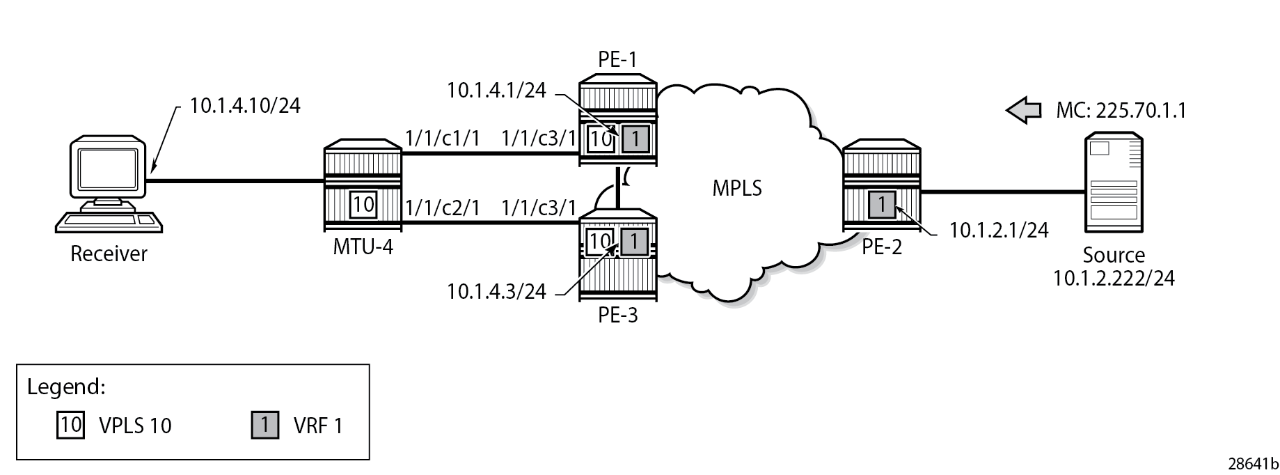
A multicast stream is emitted by the source connected to PE-2 with group address 225.70.1.1. A multicast receiver connected to MTU-4 joins group 225.70.1.1. MTU-4 is connected to PE-1 and PE-3 through an all-active multi-homing EVPN Ethernet segment comprising LAG 1. On MTU-4, LAG 1 comprises port 1/1/c1/1 and 1/1/c2/1, and this LAG is used in VPLS 10. On PE-1 and PE-3, VPLS 10 is interconnected with VPRN 1 through an Integrated Routing and Bridging (IRB) interface. VPRN 1 is defined in PE-1, PE-2, and PE-3, and uses NG-MVPN for transporting the multicast traffic through the core of the network. See the EVPN for MPLS Tunnels and EVPN for MPLS Tunnels in Routed VPLS chapters for more information about EVPN. See the "NG-MVPN Configuration with MPLS" and "NG-MVPN Configuration with PIM" chapters in the Layer 3 Services volume of the 7450 ESS, 7750 SR, and 7950 XRS Advanced Configuration Guide - Part II for more information about NG-MVPN.
Configuration
The initial configuration on the PE nodes includes the following:
Cards, MDAs, ports
Router interfaces
IS-IS (alternatively, OSPF can be used)
MPLS tunnels between the PEs: LDP- or RSVP-based
BGP is required at the core of the network, using the VPN IPv4 and MVPN IPv4 address families between all PEs, for supporting unicast and multicast traffic on VPRN services, and additionally using the EVPN address family between PE-1 and PE-3 to support EVPN services. The BGP configurations for PE-1, PE-2, and PE-3 are as follows:
# on PE-1:
configure {
    router {
        autonomous-system 64496
        bgp {
            vpn-apply-export true
            vpn-apply-import true
            rapid-withdrawal true
            peer-ip-tracking true
            family {
                ipv4 false
                vpn-ipv4 true
                mvpn-ipv4 true
                evpn true
            }
            ebgp-default-reject-policy {
                import false
                export false
            }
            rapid-update {
                evpn true
            }
            group "iBGP" { }
            neighbor "192.0.2.2" {
                group "iBGP"
                peer-as 64496
            }
            neighbor "192.0.2.3" {
                group "iBGP"
                peer-as 64496
            }
        }
    }
}
# on PE-2:
configure {
    router {
        autonomous-system 64496
        bgp {
            vpn-apply-export true
            vpn-apply-import true
            rapid-withdrawal true
            peer-ip-tracking true
            family {
                ipv4 false
                vpn-ipv4 true
                mvpn-ipv4 true
            }
            ebgp-default-reject-policy {
                import false
                export false
            }
            rapid-update {
                evpn true
            }
            group "iBGP" { }
            neighbor "192.0.2.1" {
                group "iBGP"
                peer-as 64496
            }
            neighbor "192.0.2.3" {
                group "iBGP"
                peer-as 64496
            }
        }
    }
}
# on PE-3:
configure {
    router {
        autonomous-system 64496
        bgp {
            vpn-apply-export true
            vpn-apply-import true
            rapid-withdrawal true
            peer-ip-tracking true
            family {
                ipv4 false
                vpn-ipv4 true
                mvpn-ipv4 true
                evpn true
            }
            ebgp-default-reject-policy {
                import false
                export false
            }
            rapid-update {
                evpn true
            }
            group "iBGP" { }
            neighbor "192.0.2.1" {
                group "iBGP"
                peer-as 64496
            }
            neighbor "192.0.2.2" {
                group "iBGP"
                peer-as 64496
            }
        }
    }
}
The receiver connected to MTU-4 joins group 225.70.1.1, and the corresponding multicast stream is emitted by the source that is connected to PE-2. MTU-4 is connected to PE-1 and PE-3 through an all-active multi-homing EVPN Ethernet segment comprising LAG 1. The VPLS and the LAG on MTU-4 are defined as follows:
# on MTU-4:
configure {
    service {
        vpls "mcast-vpls" {
            admin-state enable
            service-id 10
            customer "1"
            igmp-snooping {
                admin-state enable
            }
            sap 1/2/c1/1 { }
            sap lag-1:10 { }
        }
    }
}

configure {
    lag "lag-1" {
        admin-state enable
        encap-type dot1q
        mode access
        port 1/1/c1/1 { }
        port 1/1/c2/1 { }
    }
}
The all-active multi-homing Ethernet segment esi-13 is configured identically on PE-1 and PE-3, as follows. See the EVPN for MPLS Tunnels and EVPN for MPLS Tunnels in Routed VPLS chapters for more information.
# on PE-1 and PE-3:
configure {
    service {
        system {
            bgp {
                evpn {
                    ethernet-segment "esi-13" {
                        admin-state enable
                        esi 0x01000000001300000001
                        multi-homing-mode all-active
                        df-election {
                            es-activation-timer 3
                            service-carving-mode manual
                            manual {
                                preference {
                                    mode non-revertive
                                    value 30
                                }
                            }
                        }
                        association {
                            lag "lag-1" { }
                        }
                    }
                }
            }
        }
    }
}
The multi-homed access circuits of esi-13 are located on port 1/1/c3/1 for PE-1 and PE-3, so the LAG is configured identically, as follows:
# on PE-1 and PE-3:
configure {
    lag "lag-1" {
        admin-state enable
        encap-type dot1q
        mode access
        port 1/1/c3/1 { }
    }
}
Also, the EVPN VPLS service with ID 10 is configured identically on PE-1 and PE-3, as follows. The mcast-vpls name is needed to link VPLS 10 to VPRN 1 at a later stage, without requiring a physical loop or hairpin. The routed-vpls command enables the VPLS to become an R-VPLS. The igmp-snooping and mrouter-port true commands are required for multicast to work correctly in an all-active multi-homed scenario.
# on PE-1 and PE-3:
configure {
    service {
        vpls "mcast-vpls" {
            admin-state enable
            service-id 10
            customer "1"
            routed-vpls {
                multicast {
                    ipv4 {
                        igmp-snooping {
                            mrouter-port true
                        }
                    }
                }
            }
            bgp 1 { }
            igmp-snooping {
                admin-state enable
            }
            bgp-evpn {
                evi 111
                mpls 1 {
                    admin-state enable
                    ingress-replication-bum-label true
                    auto-bind-tunnel {
                        resolution any
                    }
                }
            }
            sap lag-1:10 { }
        }
    }
}
The VPRN service with ID 1 provides the connection toward MTU-4 via VPLS 10, through the int-MCAST-VPLS interface with address 10.1.4.1/24 on PE-1, and with address 10.1.4.3/24 on PE-3. This L3 interface is linked to VPLS 10 with the vpls "mcast-vpls" { } command. The int-MCAST-VPLS interface is also included in the IGMP and PIM configurations of VPRN 1. The full configuration of VPRN 1 on PE-1 is as follows. The configuration of VPRN 1 on PE-3 is similar.
# on PE-1:
configure {
    service {
        vprn "VPRN 1" {
            admin-state enable
            service-id 1
            customer "1"
            igmp {
                ssm-translate {
                    group-range start 225.70.1.1 end 225.70.255.255 {
                        source 10.1.2.222 { }
                    }
                }
                interface "int-MCAST-VPLS" { }
                interface "int-PE-1-CE-1" { }
            }
            pim {
                interface "int-MCAST-VPLS" { }
                interface "system" { }
            }
            mvpn {
                c-mcast-signaling bgp
                mdt-type receiver-only
                auto-discovery {
                    type bgp
                }
                vrf-target {
                    unicast true
                }
                provider-tunnel {
                    inclusive {
                        mldp {
                            admin-state enable
                        }
                    }
                    selective {
                        data-threshold {
                            group-prefix 224.0.0.0/4 {
                                threshold 1
                            }
                        }
                        mldp {
                            admin-state enable
                        }
                    }
                }
            }
            bgp-ipvpn {
                mpls {
                    admin-state enable
                    route-distinguisher "64496:1"
                    vrf-target {
                        community "target:64496:1"
                    }
                    auto-bind-tunnel {
                        resolution any
                    }
                }
            }
            interface "int-MCAST-VPLS" {
                ipv4 {
                    primary {
                        address 10.1.4.1
                        prefix-length 24
                    }
                }
                vpls "mcast-vpls" { }
            }
            interface "int-PE-1-CE-1" {
                ipv4 {
                    primary {
                        address 10.1.1.1
                        prefix-length 24
                    }
                }
                sap 1/2/c1/1 { }
            }
            interface "system" {
                loopback true
                ipv4 {
                    primary {
                        address 192.0.2.101
                        prefix-length 32
                    }
                }
            }
        }
    }
}
The full configuration of VPRN 1 on PE-2 is as follows. The int-PE-2-CE-2-source interface provides the connection to the multicast source.
# on PE-2:
configure {
    service {
        vprn "VPRN 1" {
            admin-state enable
            service-id 1
            customer "1"
            pim {
                interface "int-PE-2-CE-2-source" { }
                interface "system" { }
            }
            mvpn {
                c-mcast-signaling bgp
                mdt-type sender-only
                auto-discovery {
                    type bgp
                }
                vrf-target {
                    unicast true
                }
                provider-tunnel {
                    inclusive {
                        mldp {
                            admin-state enable
                        }
                    }
                    selective {
                        data-threshold {
                            group-prefix 224.0.0.0/4 {
                                threshold 1
                            }
                        }
                        mldp {
                            admin-state enable
                        }
                    }
                }
            }
            bgp-ipvpn {
                mpls {
                    admin-state enable
                    route-distinguisher "64496:1"
                    vrf-target {
                        community "target:64496:1"
                    }
                    auto-bind-tunnel {
                        resolution any
                    }
                }
            }
            interface "int-PE-2-CE-2-source" {
                ipv4 {
                    primary {
                        address 10.1.2.1
                        prefix-length 24
                    }
                }
                sap 1/2/c1/1 { }
            }
            interface "system" {
                loopback true
                ipv4 {
                    primary {
                        address 192.0.2.102
                        prefix-length 32
                    }
                }
            }
        }
    }
}
Verification
The following command shows that esi-13 is an all-active multi-homed Ethernet segment, on PE-1. The same command can be executed on PE-3.
[/]
A:admin@PE-1# show service system bgp-evpn ethernet-segment name "esi-13"

===============================================================================
Service Ethernet Segment
===============================================================================
Name                    : esi-13
Eth Seg Type            : None
Admin State             : Enabled            Oper State         : Up
ESI                     : 01:00:00:00:00:13:00:00:00:01
Oper ESI                : 01:00:00:00:00:13:00:00:00:01
Auto-ESI Type           : None
AC DF Capability        : Include
Multi-homing            : allActive          Oper Multi-homing  : allActive
ES SHG Label            : 524282
Source BMAC LSB         : None
Lag                     : lag-1
ES Activation Timer     : 3 secs
Oper Group              : (Not Specified)
Svc Carving             : manual             Oper Svc Carving   : manual
Cfg Range Type          : lowest-pref

-------------------------------------------------------------------------------
DF Pref Election Information
-------------------------------------------------------------------------------
Preference     Preference     Last Admin Change        Oper Pref      Do No
Mode           Value                                   Value          Preempt
-------------------------------------------------------------------------------
non-revertive  30             07/20/2023 11:24:10      30             Disabled
-------------------------------------------------------------------------------
EVI Ranges: <none>
ISID Ranges: <none>
Vprn NextHop EVI Ranges : <none>
===============================================================================
The output from the following commands on PE-1 and PE-3 shows that for esi-13, PE-1 is Non-Designated Forwarder (NDF), whereas PE-3 is Designated Forwarder (DF).
[/]
A:admin@PE-1# show service id 10 ethernet-segment "esi-13"

===============================================================================
SAP Ethernet-Segment Information
===============================================================================
SAP                   Eth-Seg                          Status
-------------------------------------------------------------------------------
lag-1:10              esi-13                           NDF
===============================================================================
No sdp entries
No vxlan instance entries
[/]
A:admin@PE-3# show service id 10 ethernet-segment "esi-13"

===============================================================================
SAP Ethernet-Segment Information
===============================================================================
SAP                   Eth-Seg                          Status
-------------------------------------------------------------------------------
lag-1:10              esi-13                           DF
===============================================================================
No sdp entries
No vxlan instance entries
A stream with group address 225.70.1.1 is started by the multicast source and joined by the multicast receiver connected to MTU-4. This stream is forwarded from PE-2 to PE-3; PE-1 is not involved in the forwarding.
PE-1 maintains IGMP state for group 225.70.1.1 in VPRN 1, and so does PE-3. PE-1 and PE-3 synchronize IGMP state using a data-driven mechanism. The forwarding list includes the int-MCAST-VPLS interface, as follows:
[/]
A:admin@PE-1# show router 1 igmp group 225.70.1.1 interfaces
===============================================================================
IGMP Interface Groups
===============================================================================

(*,225.70.1.1)                                            UpTime: 0d 00:01:41
    Fwd List  : int-MCAST-VPLS
-------------------------------------------------------------------------------
Entries : 1
===============================================================================
PE-1 maintains PIM state for group 225.70.1.1, as follows. The outgoing interfaces list is empty and the forwarding rate is zero; both are indications that PE-1 is not forwarding any multicast traffic.
[/]
A:admin@PE-1# show router 1 pim group 225.70.1.1 detail

===============================================================================
PIM Source Group ipv4
===============================================================================
Group Address      : 225.70.1.1
Source Address     : 10.1.2.222
RP Address         : 0
Advt Router        : 192.0.2.2
Flags              :                    Type               : (S,G)
Mode               : sparse
MRIB Next Hop      : 192.0.2.2
MRIB Src Flags     : remote
Keepalive Timer Exp: 0d 00:01:50
Up Time            : 0d 00:02:34        Resolved By        : rtable-u

Up JP State        : Not Joined         Up JP Expiry       : 0d 00:00:00
Up JP Rpt          : Not Joined StarG   Up JP Rpt Override : 0d 00:00:00

Register State     : No Info
Reg From Anycast RP: No

Rpf Neighbor       : 192.0.2.2
Incoming Intf      : mpls-if-73728
Outgoing Intf List :

Curr Fwding Rate   : 0.000 kbps
Forwarded Packets  : 0                  Discarded Packets  : 0
Forwarded Octets   : 0                  RPF Mismatches     : 0
Spt threshold      : 0 kbps             ECMP opt threshold : 7
Admin bandwidth    : 1 kbps
-------------------------------------------------------------------------------
Groups : 1
===============================================================================
PE-2 and PE-3 are forwarding the stream as indicated by the PIM state for this group, as follows:
[/]
A:admin@PE-2# show router 1 pim group 225.70.1.1 detail

===============================================================================
PIM Source Group ipv4
===============================================================================
Group Address      : 225.70.1.1
Source Address     : 10.1.2.222
RP Address         : 0
Advt Router        : 192.0.2.2
Flags              :                    Type               : (S,G)
Mode               : sparse
MRIB Next Hop      : 10.1.2.222
MRIB Src Flags     : direct
Keepalive Timer    : Not Running
Up Time            : 0d 00:02:04        Resolved By        : rtable-u

Up JP State        : Joined             Up JP Expiry       : 0d 00:00:00
Up JP Rpt          : Not Joined StarG   Up JP Rpt Override : 0d 00:00:00

Register State     : No Info
Reg From Anycast RP: No

Rpf Neighbor       : 10.1.2.222
Incoming Intf      : int-PE-2-CE-2-source
Outgoing Intf List : mpls-if-73728 (mpls-if-73730)

Curr Fwding Rate   : 9745.632 kbps
Forwarded Packets  : 60341              Discarded Packets  : 0
Forwarded Octets   : 89425362           RPF Mismatches     : 0
Spt threshold      : 0 kbps             ECMP opt threshold : 7
Admin bandwidth    : 1 kbps
-------------------------------------------------------------------------------
Groups : 1
===============================================================================
[/]
A:admin@PE-3# show router 1 pim group 225.70.1.1 detail

===============================================================================
PIM Source Group ipv4
===============================================================================
Group Address      : 225.70.1.1
Source Address     : 10.1.2.222
RP Address         : 0
Advt Router        : 192.0.2.2
Flags              :                    Type               : (S,G)
Mode               : sparse
MRIB Next Hop      : 192.0.2.2
MRIB Src Flags     : remote
Keepalive Timer Exp: 0d 00:01:48
Up Time            : 0d 00:02:35        Resolved By        : rtable-u

Up JP State        : Joined             Up JP Expiry       : 0d 00:00:24
Up JP Rpt          : Not Joined StarG   Up JP Rpt Override : 0d 00:00:00

Register State     : No Info
Reg From Anycast RP: No

Rpf Neighbor       : 192.0.2.2
Incoming Intf      : mpls-if-73728
Incoming SPMSI Intf: mpls-if-73730
Outgoing Intf List : int-MCAST-VPLS

Curr Fwding Rate   : 9745.632 kbps
Forwarded Packets  : 86065              Discarded Packets  : 0
Forwarded Octets   : 127548330          RPF Mismatches     : 0
Spt threshold      : 0 kbps             ECMP opt threshold : 7
Admin bandwidth    : 1 kbps
-------------------------------------------------------------------------------
Groups : 1
===============================================================================
The outgoing interfaces on PE-2 and PE-3 are the mpls-if-73728 PMSI interface and the int-MCAST-VPLS interfaces, respectively. The properties of the S-PMSI interface are as follows:
[/]
A:admin@PE-2# show router 1 pim tunnel-interface "mpls-if-73728" detail

===============================================================================
PIM Interface ipv4 mpls-if-73728
===============================================================================
Admin Status       : Up                 Oper Status        : Up
IPv4 Admin Status  : Up                 IPv4 Oper Status   : Up
DR                 : 192.0.2.2
Auto-created       : No
Transport Type     : MVPN-Pmsi

-------------------------------------------------------------------------------
PIM Group Source
-------------------------------------------------------------------------------
Group Address      : 225.70.1.1
Source Address     : 10.1.2.222
Interface          : mpls-if-73728      Type               : (S,G)
RP Address         : 0.0.0.0
Up Time            : 0d 00:02:12

Join Prune State   : Join               Expires            : Never
Prune Pend Expires : N/A

Assert State       : No Info
-------------------------------------------------------------------------------
Interfaces : 1
===============================================================================
The stream is received on the incoming PMSI interface mpls-if-73728 on PE-3. The properties of this PMSI interface are as follows:
[/]
A:admin@PE-3# show router 1 pim tunnel-interface "mpls-if-73728" detail

===============================================================================
PIM Interface ipv4 mpls-if-73728
===============================================================================
Admin Status       : Up                 Oper Status        : Up
IPv4 Admin Status  : Up                 IPv4 Oper Status   : Up
DR                 : 192.0.2.2
Auto-created       : No
Transport Type     : MVPN-Pmsi
-------------------------------------------------------------------------------
Interfaces : 1
===============================================================================
PE-3 sends this multicast stream to MTU-4, which in turn sends it to the receiver that sent the join, so the path taken by the multicast stream runs via PE-2, PE-3, and MTU-4.
In the example from Multicast From an EVPN-MPLS Service Into an R-VPLS With All-Active EVPN Multi-Homing, and the commands and traces that follow, PE-1 is the active IGMP querier using address 10.1.4.1, sending out the queries across the L2 domain. The group queries are sent by PE-1 to PE-3 across the EVPN-MPLS tunnel because PE-3 is DF for esi-13, then forwarded onto MTU-4 to reach the (potential) receiver. MTU-4 relays the IGMP responses from the receiver to one of the links; in this example, the link between MTU-4 and PE-1. When the IGMP response for joining the 225.1.70.1 stream is received on PE-1, this event is signaled across the EVPN-MPLS tunnel because it is received over esi-13. This way, the IGMP state is synchronized between PE-3 and PE-1 in a data-driven way.
The basic IGMP snooping state for VPLS 10 on PE-1 and PE-3 is as follows. The output shows that IGMP snooping is enabled on ports sap:lag-1:10, rvpls, and evpn-mpls.
[/]
A:admin@PE-1# show service id 10 igmp-snooping base

===============================================================================
IGMP Snooping Base info for service 10
===============================================================================
Admin State : Up
Querier     : 10.1.4.1 on rvpls int-MCAST-VPLS
SBD service : N/A
Evpn-proxy  : Disabled
-------------------------------------------------------------------------------
Port                       Oper MRtr Pim  Send Max  Max  Max   MVR       Num
Id                         Stat Port Port Qrys Grps Srcs Grp   From-VPLS Grps
                                                         Srcs
-------------------------------------------------------------------------------
sap:lag-1:10               Up   No   No   No   None None None  Local     1
rvpls                      Up   Yes  No   N/A  N/A  N/A  N/A   N/A       N/A
evpn-mpls
                           Up   Yes  No   N/A  N/A  N/A  N/A   N/A       N/A
===============================================================================
[/]
A:admin@PE-3# show service id 10 igmp-snooping base

===============================================================================
IGMP Snooping Base info for service 10
===============================================================================
Admin State : Up
Querier     : 10.1.4.1 on evpn-mpls
SBD service : N/A
Evpn-proxy  : Disabled
-------------------------------------------------------------------------------
Port                       Oper MRtr Pim  Send Max  Max  Max   MVR       Num
Id                         Stat Port Port Qrys Grps Srcs Grp   From-VPLS Grps
                                                         Srcs
-------------------------------------------------------------------------------
sap:lag-1:10               Up   No   No   No   None None None  Local     1
rvpls                      Up   Yes  No   N/A  N/A  N/A  N/A   N/A       N/A
evpn-mpls
                           Up   Yes  No   N/A  N/A  N/A  N/A   N/A       N/A
===============================================================================
PE-1 sends the IGMP queries on VPRN 1 via the int-MCAST-VPLS interface, so the VPLS that is referenced in the int-MCAST-VPLS interface registers the ports on which the IGMP queries are received as multicast router ports. EVPN-MPLS tunnels are always multicast router ports. The following output displays the source addresses of the multicast routers:
[/]
A:admin@PE-1# show service id 10 igmp-snooping mrouters

===============================================================================
IGMP Snooping Multicast Routers for service 10
===============================================================================
MRouter          Port Id                    Up Time        Expires   Version
-------------------------------------------------------------------------------
10.1.4.1         rvpls                      0d 00:21:54    231s      3
-------------------------------------------------------------------------------
Number of mrouters: 1
===============================================================================
[/]
A:admin@PE-3# show service id 10 igmp-snooping mrouters

===============================================================================
IGMP Snooping Multicast Routers for service 10
===============================================================================
MRouter          Port Id                    Up Time        Expires   Version
-------------------------------------------------------------------------------
10.1.4.1         evpn-mpls                  0d 00:21:25    229s      3
-------------------------------------------------------------------------------
Number of mrouters: 1
===============================================================================
The IGMP snooping querier properties for VPLS 10 on PE-1 and PE-3 are as follows:
[/]
A:admin@PE-1# show service id 10 igmp-snooping querier

===============================================================================
IGMP Snooping Querier info for service 10
===============================================================================
Port Id                 : r-vpls int-MCAST-VPLS
IP Address              : 10.1.4.1
Expires                 : 130s
Up Time                 : 0d 00:21:30
Version                 : 3

General Query Interval  : 125s
Query Response Interval : 10.0s
Robust Count            : 2
===============================================================================

[/]
A:admin@PE-3# show service id 10 igmp-snooping querier

===============================================================================
IGMP Snooping Querier info for service 10
===============================================================================
Port Id                 : evpn-mpls
IP Address              : 10.1.4.1
Expires                 : 253s
Up Time                 : 0d 00:21:01
Version                 : 3

General Query Interval  : 125s
Query Response Interval : 10.0s
Robust Count            : 2
===============================================================================
IGMP snooping in VPLS 10 registers the reports in the IGMP snooper port database (port-db). The port-db can be displayed with a show command, and specifying a SAP limits the output generated by this command, as follows:
[/]
A:admin@PE-1# show service id 10 igmp-snooping port-db sap lag-1:10

===============================================================================
IGMP Snooping SAP lag-1:10 Port-DB for service 10
===============================================================================
Group Address   Mode    Type    From-VPLS  Up Time        Expires  Num   MC
                                                                   Src   Stdby
-------------------------------------------------------------------------------
225.70.1.1      exclude dynamic local      0d 00:04:10    never    0
-------------------------------------------------------------------------------
Number of groups: 1
===============================================================================

[/]
A:admin@PE-3# show service id 10 igmp-snooping port-db sap lag-1:10

===============================================================================
IGMP Snooping SAP lag-1:10 Port-DB for service 10
===============================================================================
Group Address   Mode    Type    From-VPLS  Up Time        Expires  Num   MC
                                                                   Src   Stdby
-------------------------------------------------------------------------------
225.70.1.1      exclude dynamic local      0d 00:04:12    230s     0
-------------------------------------------------------------------------------
Number of groups: 1
===============================================================================
IGMP snooping statistics show the number of received, transmitted, and forwarded IGMP messages per type, and also provide drop counts per error type, as follows:
[/]
A:admin@PE-1# show service id 10 igmp-snooping statistics

===============================================================================
IGMP Snooping Statistics for service 10
===============================================================================
Message Type            Received      Transmitted   Forwarded
-------------------------------------------------------------------------------
General Queries         0             0             17
Group Queries           0             2             2
Group-Source Queries    0             0             0
V1 Reports              0             0             0
V2 Reports              0             0             0
V3 Reports              12            6             6
V2 Leaves               0             0             0
Unknown Type            0             N/A           0
EVPN SMET Routes        0             0             N/A
-------------------------------------------------------------------------------
Drop Statistics
-------------------------------------------------------------------------------
Bad Length               : 0
Bad IP Checksum          : 0
Bad IGMP Checksum        : 0
Bad Encoding             : 0
No Router Alert          : 0
Zero Source IP           : 0
Wrong Version            : 0
Lcl-Scope Packets        : 0
Rsvd-Scope Packets       : 0

Send Query Cfg Drops     : 0
Import Policy Drops      : 0
Exceeded Max Num Groups  : 0
Exceeded Max Num Sources : 0
Exceeded Max Num Grp Srcs: 0
MCAC Policy Drops        : 0
MCS Failures             : 0

MVR From VPLS Cfg Drops  : 0
MVR To SAP Cfg Drops     : 0
===============================================================================

[/]
A:admin@PE-3# show service id 10 igmp-snooping statistics

===============================================================================
IGMP Snooping Statistics for service 10
===============================================================================
Message Type            Received      Transmitted   Forwarded
-------------------------------------------------------------------------------
General Queries         12            0             9
Group Queries           2             2             0
Group-Source Queries    0             0             0
V1 Reports              0             0             0
V2 Reports              0             0             0
V3 Reports              12            6             0
V2 Leaves               0             0             0
Unknown Type            0             N/A           0
EVPN SMET Routes        0             0             N/A
-------------------------------------------------------------------------------
Drop Statistics
-------------------------------------------------------------------------------
Bad Length               : 0
Bad IP Checksum          : 0
Bad IGMP Checksum        : 0
Bad Encoding             : 0
No Router Alert          : 0
Zero Source IP           : 0
Wrong Version            : 0
Lcl-Scope Packets        : 0
Rsvd-Scope Packets       : 0

Send Query Cfg Drops     : 0
Import Policy Drops      : 0
Exceeded Max Num Groups  : 0
Exceeded Max Num Sources : 0
Exceeded Max Num Grp Srcs: 0
MCAC Policy Drops        : 0
MCS Failures             : 0

MVR From VPLS Cfg Drops  : 0
MVR To SAP Cfg Drops     : 0
===============================================================================
Debug
Debugging is useful for troubleshooting purposes, and the debug configuration used on PE-1 and PE-3 for checking IGMP and IGMP snooping functionalities is as follows:
debug {
    router "VPRN 1" {
        igmp {
            packet {
                dropped true
                ingress true
                egress true
            }
        }
    }
    service {
        vpls "mcast-vpls" {
            igmp-snooping {
                packet {
                    dropped true
                    ingress true
                    egress true
                    evpn-mpls true
                    sap lag-1:10 { }
                }
            }
        }
    }
}
When group 225.70.1.1 is joined, the trace on PE-1 is as follows. Event 4 is the IGMPv3 join message for group 225.70.1.1 received on SAP lag-1:10 in VPLS 10 from the receiver. The reception of this message is synchronized across the EVPN-MPLS tunnel for VPLS 10, as indicated by event 5. Event 6 is the IGMPv3 join message as received on interface int-MCAST-VPLS by VPRN 1.
4 2023/07/20 11:42:52.720 CEST MINOR: DEBUG #2001 Base IGMP
"IGMP: RX packet on svc 10
  from chaddr 04:0f:ff:00:01:41
  Port  : sap lag-1:10
  SrcIp : 0.0.0.0
  DstIp : 224.0.0.22
  Type  : V3 REPORT
    Num Group Records: 1
        Group Record Type: CHG_TO_EXCL (4), AuxDataLen 0, Num Sources 0
          Group Addr: 225.70.1.1

"

5 2023/07/20 11:42:52.720 CEST MINOR: DEBUG #2001 Base IGMP
"IGMP: TX packet on svc 10
  from chaddr 5e:00:00:16:04:0f
  send towards ES : esi-13
  Port  : evpn-mpls
  SrcIp : 0.0.0.0
  DstIp : 224.0.0.22
  Type  : V3 REPORT
    Num Group Records: 1
        Group Record Type: CHG_TO_EXCL (4), AuxDataLen 0, Num Sources 0
          Group Addr: 225.70.1.1

"

---snip---

6 2023/07/20 11:42:52.720 CEST MINOR: DEBUG #2001 vprn1 IGMP[2]
"IGMP[2]: RX-PKT
[000 00:28:13.480] IGMP interface int-MCAST-VPLS [ifIndex 4] V3 PDU: 0.0.0.0 -> 224.0.0.22 pduLen 16
    Type: V3 REPORT maxrespCode 0x0 checkSum 0xf7b6
    Num Group Records: 1
        Group Record 0
        Type: CHG_TO_EXCL, AuxDataLen 0, Num Sources 0
        Mcast Addr: 225.70.1.1
        Source Address List

"
The trace on PE-3 is as follows. Event 5 is the reception of the snooping state synchronization across the EVPN-MPSL tunnel, and event 8 is the IGMPv3 join as received on interface int-MCAST-VPLS by VPRN 1.
5 2023/07/20 11:42:52.726 CEST MINOR: DEBUG #2001 Base IGMP
"IGMP: RX packet on svc 10
  from chaddr 04:0f:ff:00:01:41
  received via evpn-mpls on ES : esi-13
  Port  : sap lag-1:10
  SrcIp : 0.0.0.0
  DstIp : 224.0.0.22
  Type  : V3 REPORT
    Num Group Records: 1
        Group Record Type: CHG_TO_EXCL (4), AuxDataLen 0, Num Sources 0
          Group Addr: 225.70.1.1

"
---snip---

8 2023/07/20 11:42:52.726 CEST MINOR: DEBUG #2001 vprn1 IGMP[2]
"IGMP[2]: RX-PKT
[000 00:28:07.620] IGMP interface int-MCAST-VPLS [ifIndex 4] V3 PDU: 0.0.0.0 -> 224.0.0.22 pduLen 16
    Type: V3 REPORT maxrespCode 0x0 checkSum 0xf7b6
    Num Group Records: 1
        Group Record 0
        Type: CHG_TO_EXCL, AuxDataLen 0, Num Sources 0
        Mcast Addr: 225.70.1.1
        Source Address List

"
Similar events are logged when the multicast receiver leaves the 225.70.1.1 group.
Conclusion
By connecting customers to EVPN-MPLS VPRN/IES routed services via an R-VPLS, service providers can offer IPv4 multicast services to customers in an all-active multi-homing scenario.