EVPN for VXLAN Tunnels (Layer 3)
This chapter provides information about EVPN for VXLAN tunnels (Layer 3).
Topics in this chapter include:
Applicability
This chapter is applicable to SR OS and was initially written for Release 12.0.R4. The MD-CLI in the current edition is based on SR OS Release 21.10.R3. Ethernet Virtual Private Network (EVPN) is a control plane technology and does not have line card hardware dependencies.
Chapter EVPN for VXLAN Tunnels (Layer 2) is prerequisite reading.
Overview
As discussed in the EVPN for VXLAN Tunnels (Layer 2) chapter, EVPN and VXLAN can be enabled on VPLS or R-VPLS services in SR OS. Where that chapter focuses on the use of EVPN-VXLAN layer 2 services, in other words, how EVPN-VXLAN is configured in VPLS services, this chapter describes how EVPN-VXLAN can be used to provide inter-subnet forwarding in R-VPLS and VPRN services. Inter-subnet forwarding can be provided by regular R-VPLS and VPRN services. However, EVPN provides an efficient and unified way to populate Forwarding Databases (FDBs), Address Resolution Protocol (ARP) tables, and routing tables using a single BGP address family. Inter-subnet forwarding in overlay networks would otherwise require data plane learning and the use of routing protocols on a per VPRN basis.
The SR OS solution for inter-subnet forwarding using EVPN is based on building blocks described in draft-ietf-bess-evpn-inter-subnet-forwarding and the use of the EVPN IP-prefix routes (route type 5) as described in RFC 9136. This example describes three supported common scenarios and provides the CLI configuration and required tools to troubleshoot EVPN-VXLAN in each case. The scenarios configured and described are:
-
EVPN-VXLAN in R-VPLS services
-
EVPN-VXLAN in Integrated Routing Bridging (IRB) backhaul R-VPLS services
-
EVPN-VXLAN in EVPN tunnel R-VPLS services
In all these scenarios, redundant PEs are usually deployed. If that is the case, the interaction of EVPN, IP-VPN, and the Routing Table Manager (RTM) may lead to some routing loop situations that must be avoided by using routing policies (this also may happen in traditional IP-VPN deployments when eBGP and MP-BGP interact to populate VPRN routing tables in multi-homed networks). This chapter describes when those routing loops can happen and how to avoid them.
The term IRB interface refers to an R-VPLS service bound to a VPRN IP interface. The terms IRB interface and R-VPLS interface are used interchangeably throughout this chapter.
Configuration
This section describes the configuration of EVPN-VXLAN for Layer 3 services on SR OS, as well as the available troubleshooting and show commands. The three scenarios described in the overview are analyzed independently.
EVPN-VXLAN in an R-VPLS service
EVPN-VXLAN for R-VPLS services shows the topology used in the first scenario.
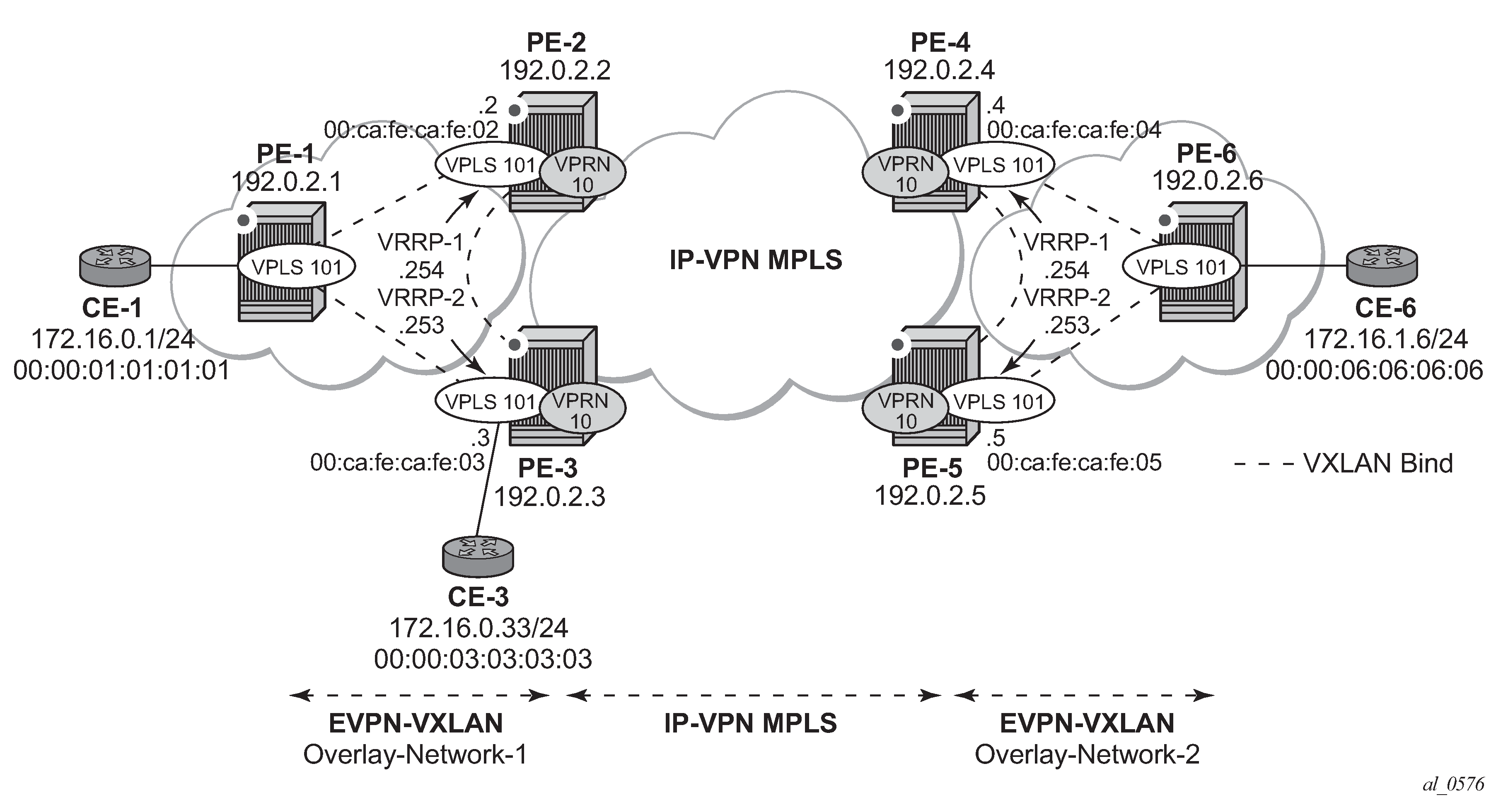
The network topology shows two overlay (VXLAN) networks interconnected by an MPLS network:
-
PE-1, PE-2, and PE-3 are part of Overlay-Network-1
-
PE-4, PE-5, and PE-6 are part of Overlay-Network-2
A Layer 2/Layer 3 service is provided to a customer to connect CE-1, CE-3, and CE-6. In this scenario, Layer 2 connectivity is provided within each overlay network and inter-subnet connectivity (Layer 3) is provided between the overlay networks. VPLS "evi-101" is defined within each overlay network and VPRN "VPRN10" connects both Layer 2 services through an IP-VPN MPLS network.
This topology can illustrate a Data Center Interconnect (DCI) example, where Overlay-Network-1 and Overlay-Network-2 are two data centers interconnected through an MPLS WAN. In this application, CE-1, CE-3, and CE-6 simulate virtual machines or appliances, PE-2/3/4/5 act as Data Center Gateways (DC GWs) and PE-1/6 as Network Virtualization Edge devices (or virtual PEs running on a compute infrastructure).
The following protocols and objects are configured beforehand:
-
The ports interconnecting the six PEs in EVPN-VXLAN for R-VPLS services are configured as network or hybrid ports and have router network interfaces defined in them. Only the ports connected to the CEs are configured as access ports.
-
The six PEs are running IS-IS for the global routing table with the four core PEs interconnected using IS-IS Level-2 point-to-point interfaces and each overlay network using IS-IS Level-1 point-to-point interfaces.
-
LDP is used as the MPLS protocol to signal transport tunnel labels among PE-2, PE-3, PE-4, and PE-5. There is no LDP running within the overlay networks.
-
The network port MTU (in all the ports sending/receiving VXLAN packets) must be at least 50 bytes (54 if dot1q encapsulation is used) greater than the service MTU to accommodate the size of the VXLAN header.
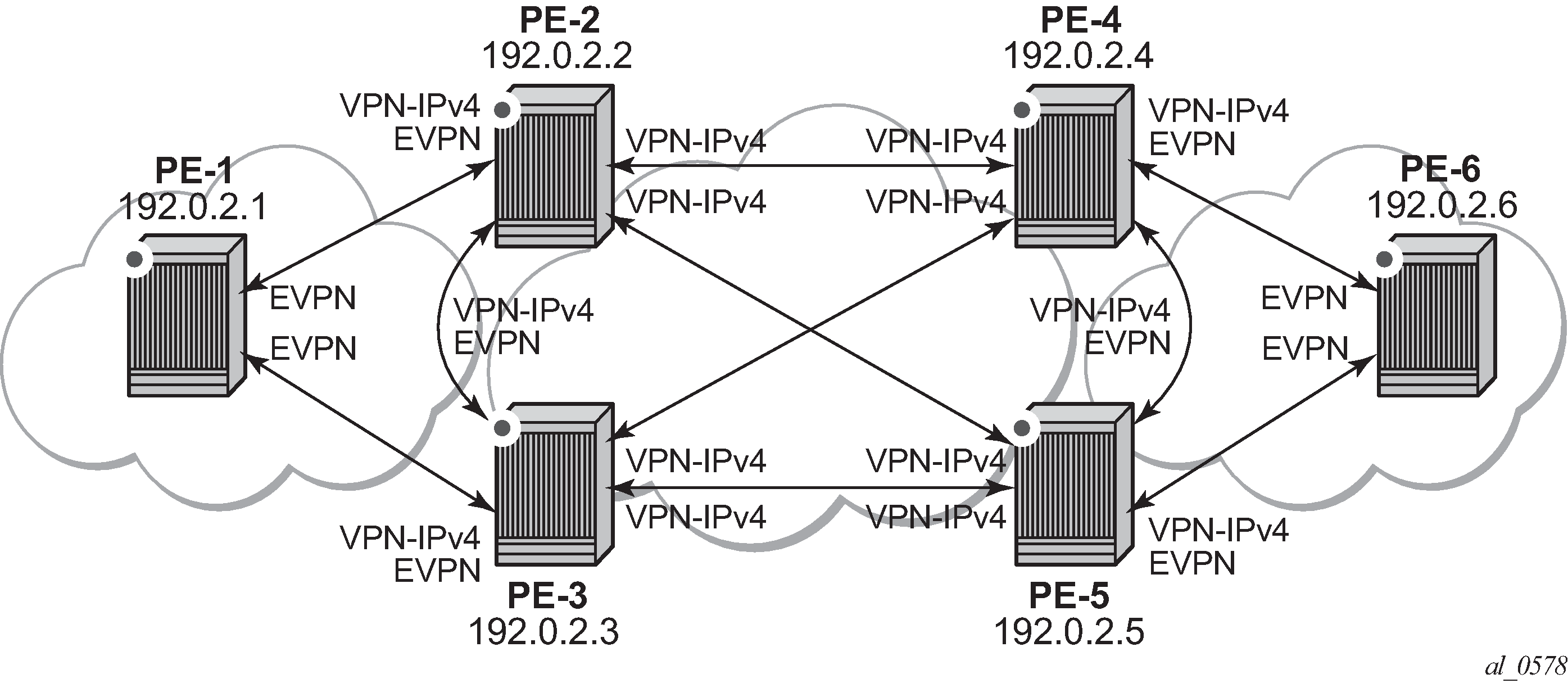
Once the IGP infrastructure and LDP in the core are enabled, BGP is configured. In this scenario, two BGP families must be enabled: EVPN within each overlay network for the exchange of MAC/IP addresses and setting up the flooding domains, and VPN-IPv4 among the four core PEs so that IP prefixes can be exchanged and resolved to MPLS tunnels in the core.
The following MD-CLI shows the BGP configuration of PE-1, which only needs the EVPN family. PE-6 has a similar BGP configuration, that is, only EVPN family is configured for its peers. The use of Route Reflectors (RRs) in these scenarios is common. Although this scenario does not use RRs, an EVPN RR could have been used in Overlay-Network-1 and Overlay-Network-2 and a separate VPN-IPv4 RR could have been used in the core IP-VPN MPLS network.
# on PE-1:
configure {
    router "Base" {
        autonomous-system 64500
        bgp {
            vpn-apply-export true
            vpn-apply-import true
            rapid-withdrawal true
            peer-ip-tracking true
            rapid-update {
                evpn true
            }
            group "DC" {
                peer-as 64500
                family {
                    evpn true
                }
            }
            neighbor "192.0.2.2" {
                group "DC"
            }
            neighbor "192.0.2.3" {
                group "DC"
            }
        }
The BGP configuration on the DC GWs is as follows:
# on PE-2:
configure {
    router "Base" {
        autonomous-system 64500
        bgp {
            vpn-apply-export true
            vpn-apply-import true
            rapid-withdrawal true
            peer-ip-tracking true
            rapid-update {
                evpn true
            }
            group "DC" {
                peer-as 64500
                family {
                    vpn-ipv4 true
                    evpn true
                }
            }
            group "WAN" {
                peer-as 64500
                family {
                    vpn-ipv4 true
                }
            }
            neighbor "192.0.2.1" {
                group "DC"
            }
            neighbor "192.0.2.3" {
                group "DC"
            }
            neighbor "192.0.2.4" {
                group "WAN"
            }
            neighbor "192.0.2.5" {
                group "WAN"
            }
        }
# on PE-3:
configure {
    router "Base" {
        autonomous-system 64500
        bgp {
            vpn-apply-export true
            vpn-apply-import true
            rapid-withdrawal true
            peer-ip-tracking true
            rapid-update {
                evpn true
            }
            group "DC" {
                peer-as 64500
                family {
                    vpn-ipv4 true
                    evpn true
                }
            }
            group "WAN" {
                peer-as 64500
                family {
                    vpn-ipv4 true
                }
            }
            neighbor "192.0.2.1" {
                group "DC"
            }
            neighbor "192.0.2.2" {
                group "DC"
            }
            neighbor "192.0.2.4" {
                group "WAN"
            }
            neighbor "192.0.2.5" {
                group "WAN"
            }
        }
The DC GWs PE-4 and PE-5 have an equivalent BGP configuration.
BGP adjacencies and enabled families shows the BGP peering sessions among the PEs and the enabled BGP families. PE-1 and PE-6 only establish an EVPN peering session with their peers (only the EVPN family is enabled on PE-1 and PE-6, even if the peer PEs are VPN-IPv4 capable as well).
When the network infrastructure is running properly, the actual service configuration, as illustrated in EVPN-VXLAN for R-VPLS services, can be carried out. The following MD-CLI shows the configuration for VPLS "evi-101" and VPRN "VPRN10" in PE-1, PE-2, and PE-3. The other overlay network has a similar configuration.
# on PE-1:
configure {
    service {
        vpls "evi-101" {
            admin-state enable
            service-id 101
            customer "1"
            vxlan {
                instance 1 {
                    vni 101
                }
            }
            proxy-arp {
                admin-state enable
            }
            bgp 1 {
                route-distinguisher "192.0.2.1:101"
                route-target {
                    export "target:64500:101"
                    import "target:64500:101"
                }
            }
            bgp-evpn {
                vxlan 1 {
                    admin-state enable
                    vxlan-instance 1
                }
            }
            sap 1/2/1:101 {
            }
        }
Proxy-ARP is disabled (default) on PE-2, as well as on the other core PEs:
# on PE-2:
configure {
    service {
        vpls "evi-101" {
            admin-state enable
            service-id 101
            customer "1"
            vxlan {
                instance 1 {
                    vni 101
                }
            }
            routed-vpls {
            }
            bgp 1 {
                route-distinguisher "192.0.2.2:101"
                route-target {
                    export "target:64500:101"
                    import "target:64500:101"
                }
            }
            bgp-evpn {
                vxlan 1 {
                    admin-state enable
                    vxlan-instance 1
                }
            }
        }
        vprn "VPRN10" {
            admin-state enable
            service-id 10
            customer "1"
            ecmp 2
            bgp-ipvpn {
                mpls {
                    admin-state enable
                    route-distinguisher "192.0.2.2:10"
                    vrf-target {
                        community "target:64500:10"
                    }
                    auto-bind-tunnel {
                        resolution filter
                        resolution-filter {
                            ldp true
                        }
                    }
                }
            }
            interface "int-1" {
                mac 00:ca:fe:ca:fe:02
                ipv4 {
                    primary {
                        address 172.16.0.2
                        prefix-length 24
                    }
                    vrrp 1 {
                        backup [172.16.0.254]
                        mac 00:ca:fe:ca:fe:54
                        priority 254
                        ping-reply true
                        traceroute-reply true
                    }
                    vrrp 2 {
                        backup [172.16.0.253]
                        mac 00:ca:fe:ca:fe:53
                        ping-reply true
                        traceroute-reply true
                    }
                }
                vpls "evi-101" {
                }
            }
        }
# on PE-3:
configure {
    service {
        vpls "evi-101" {
            admin-state enable
            service-id 101
            customer "1"
            vxlan {
                instance 1 {
                    vni 101
                }
            }
            routed-vpls {
            }
            bgp 1 {
                route-distinguisher "192.0.2.3:101"
                route-target {
                    export "target:64500:101"
                    import "target:64500:101"
                }
            }
            bgp-evpn {
                vxlan 1 {
                    admin-state enable
                    vxlan-instance 1
                }
            }
            sap 1/2/1:101 {
            }
        }
        vprn "VPRN10" {
            admin-state enable
            service-id 10
            customer "1"
            ecmp 2
            bgp-ipvpn {
                mpls {
                    admin-state enable
                    route-distinguisher "192.0.2.3:10"
                    vrf-target {
                        community "target:64500:10"
                    }
                    auto-bind-tunnel {
                        resolution filter
                        resolution-filter {
                            ldp true
                        }
                    }
                }
            }
            interface "int-1" {
                mac 00:ca:fe:ca:fe:03
                ipv4 {
                    primary {
                        address 172.16.0.3
                        prefix-length 24
                    }
                    vrrp 1 {
                        backup [172.16.0.254]
                        mac 00:ca:fe:ca:fe:54
                        ping-reply true
                        traceroute-reply true
                    }
                    vrrp 2 {
                        backup [172.16.0.253]
                        mac 00:ca:fe:ca:fe:53
                        priority 254
                        ping-reply true
                        traceroute-reply true
                    }
                }
                vpls "evi-101" {
                }
            }
        }
For details about the EVPN and VXLAN configuration in VPLS "evi-101" on PE-1, see chapter EVPN for VXLAN Tunnels (Layer 2). The configuration of VPLS "evi-101" on PE-2 and PE-3 has the following important aspects:
-
The routed-vpls command is required so that the R-VPLS can be bound to VPRN "VPRN10".
-
The service name "evi-101" is configured when the service is created and cannot be modified afterward. The service name must match the name configured in the VPLS interface in VPRN "VPRN10".
-
Even though EVPN and VXLAN are properly configured, proxy-ARP cannot be enabled in VPLS "evi-101". In an R-VPLS with EVPN-VXLAN, proxy-ARP is not supported and the VPRN ARP table is used instead. When an EVPN MAC route that includes an IP address is received in an R-VPLS, the MAC-IP pair encoded in the route is added to the ARP table of the VPRN, as opposed to the proxy-ARP table.
*[ex:/configure service vpls "evi-101" proxy-arp]
A:admin@PE-2# commit
MINOR: MGMT_CORE #4001: configure service vpls "evi-101" proxy-arp admin-state - configuration not supported on routed-vpls - configure service vpls "evi-101" routed-vpls
When configuring VPRN "VPRN10" on PE-2 and PE-3, the following considerations must be taken into account:
-
When trying to enable existing VPRN features on interfaces linked to EVPN-VXLAN R-VPLS interfaces, the radius-auth-policy command is not supported:
*[ex:/configure service vprn "VPRN10" interface "int-1"] A:admin@PE-2# radius-auth-policy "authPol1" *[ex:/configure service vprn "VPRN10" interface "int-1"] A:admin@PE-2# commit MINOR: MGMT_CORE #4001: configure service vprn "VPRN10" interface "int-1" radius-auth-policy - Combination of radius authentication policy and vpls binding not supported - configure service vprn "VPRN10" interface "int-1" -
Dynamic routing protocols such as IS-IS, RIP, or OSPF are not supported.
-
In general, no SR OS control plane generated packets are sent to the egress VXLAN bindings except for ARP, VRRP, ICMP, BFD, and Eth-CFM.
-
As shown in EVPN-VXLAN for R-VPLS services and in the CLI excerpts, VRRP can be configured on the VPLS interfaces in VPRN "VPRN10" to provide default gateway redundancy to the hosts connected to VPLS "evi-101". Two VRRP instances are configured so that VPLS "evi-101" upstream traffic can be load-balanced to PE-2 and PE-3. With VRRP on EVPN-VXLAN R-VPLS interfaces:
-
Ping-reply and traceroute-reply can be configured and are supported. BFD is also supported to speed up the fault detection.
-
standby-forwarding, even if it were configured for VRRP, would not have any effect in this configuration: the standby PE will never see any flooded traffic sent to it, so this command is not applicable to this scenario.
-
-
When a VPRN "VPRN10" VPLS interface is bound to VPLS "evi-101", EVPN advertises all the IP addresses configured for that VPLS interface as MAC routes with a static MAC indication. For the remote EVPN peers, that means that those MAC addresses linked to remote IP interfaces are protected. VRRP virtual IP/MACs are also advertised by EVPN as "static" and so protected. In the example of EVPN-VXLAN for R-VPLS services, the VPLS "evi-101" FDB in PE-1 shows the IP interface MAC addresses and VRRP MAC addresses as EvpnS:P (Static and protected MAC) as shown in the following output:
[/]
A:admin@PE-1# show service id 101 fdb detail

===============================================================================
Forwarding Database, Service 101
===============================================================================
ServId     MAC               Source-Identifier       Type     Last Change
            Transport:Tnl-Id                         Age
-------------------------------------------------------------------------------
101        00:00:01:01:01:01 sap:1/2/1:101           L/0      03/02/22 11:34:55
101        00:00:03:03:03:03 vxlan-1:                Evpn     03/02/22 11:35:37
                             192.0.2.3:101
101        00:ca:fe:ca:fe:02 vxlan-1:                EvpnS:P  03/02/22 11:35:05
                             192.0.2.2:101
101        00:ca:fe:ca:fe:03 vxlan-1:                EvpnS:P  03/02/22 11:35:37
                             192.0.2.3:101
101        00:ca:fe:ca:fe:53 vxlan-1:                EvpnS:P  03/02/22 11:35:40
                             192.0.2.3:101
101        00:ca:fe:ca:fe:54 vxlan-1:                EvpnS:P  03/02/22 11:35:08
                             192.0.2.2:101
-------------------------------------------------------------------------------
No. of MAC Entries: 6
-------------------------------------------------------------------------------
Legend:  L=Learned O=Oam P=Protected-MAC C=Conditional S=Static Lf=Leaf
===============================================================================
The VPRN "VPRN10" VRRP instances on PE-2 are the following:
[/]
A:admin@PE-2# show router 10 vrrp instance

===============================================================================
VRRP Instances
===============================================================================
Interface Name                   VR Id Own Adm  State       Base Pri   Msg Int
                                 IP        Opr  Pol Id      InUse Pri  Inh Int
-------------------------------------------------------------------------------
int-1                            1     No  Up   Master       254       1
                                 IPv4      Up   n/a         254        No
  Backup Addr: 172.16.0.254
int-1                            2     No  Up   Backup       100       1
                                 IPv4      Up   n/a         100        No
  Backup Addr: 172.16.0.253
-------------------------------------------------------------------------------
Instances : 2
===============================================================================
The ARP entries for PE-2 are the following:
[/]
A:admin@PE-2# show router 10 arp

===============================================================================
ARP Table (Service: 10)
===============================================================================
IP Address      MAC Address       Expiry    Type   Interface
-------------------------------------------------------------------------------
172.16.0.2      00:ca:fe:ca:fe:02 00h00m00s Oth[I] int-1
172.16.0.3      00:ca:fe:ca:fe:03 00h00m00s Evp[I] int-1
172.16.0.253    00:ca:fe:ca:fe:53 00h00m00s Oth    int-1
172.16.0.254    00:ca:fe:ca:fe:54 00h00m00s Oth[I] int-1
-------------------------------------------------------------------------------
No. of ARP Entries: 4
===============================================================================
EVPN-VXLAN in IRB backhaul R-VPLS services
EVPN-VXLAN for IRB backhaul R-VPLS services illustrates the second inter-subnet forwarding scenario, where Layer 3 connectivity must be provided not only between the overlay networks but also within each overlay network. In the example shown in EVPN-VXLAN for IRB backhaul R-VPLS services, a customer (tenant) has different subnets and connectivity must be provided across all of them (CE-1, CE-3, and CE-6 must be able to communicate), bearing in mind that EVPN-VXLAN is enabled in each overlay network and IP-VPN MPLS is used to interconnect both overlay networks. VPLS "evi-201" is an IRB Backhaul R-VPLS service because it provides connectivity to the VPRN instances.
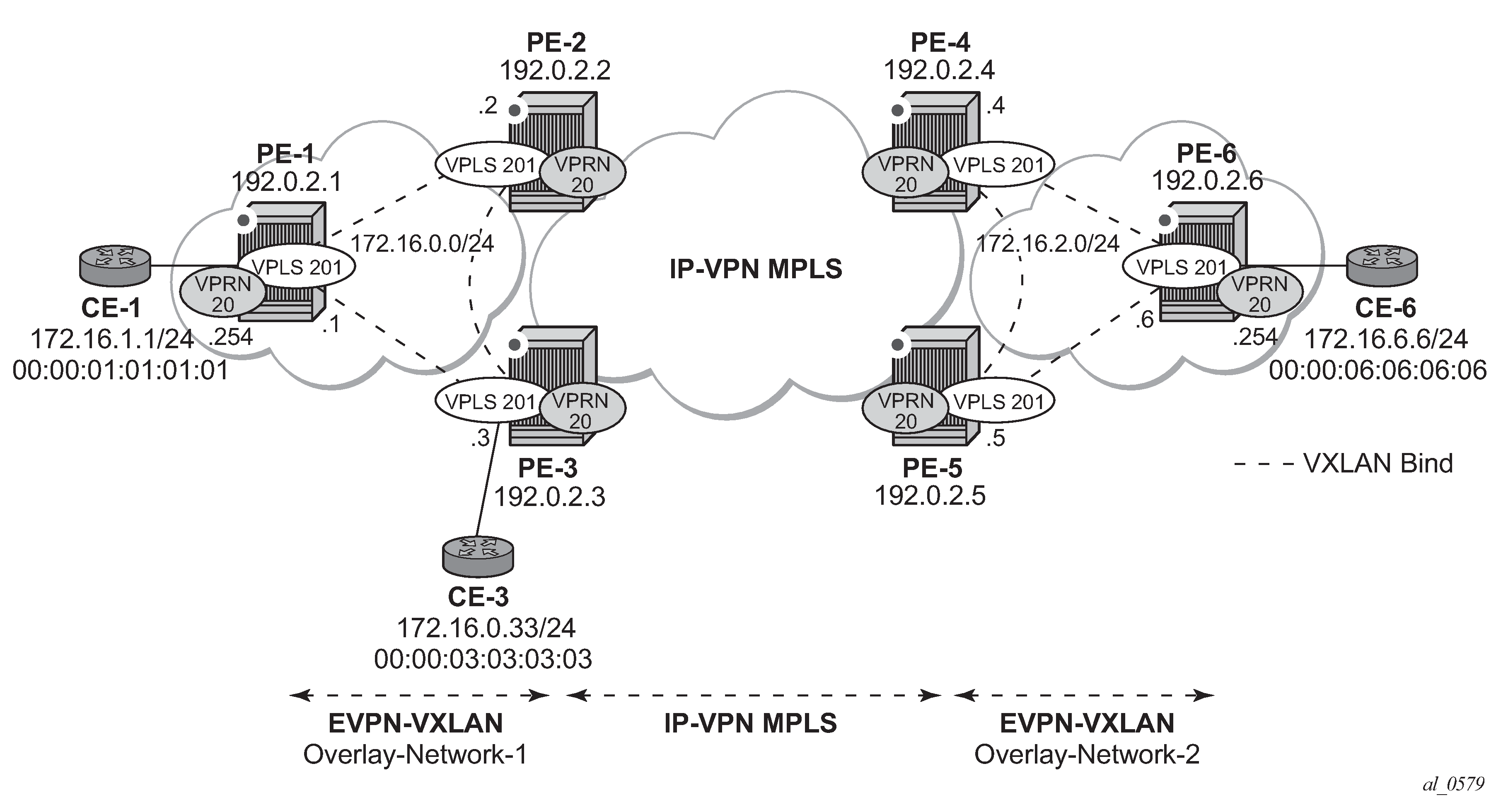
From a BGP peering perspective, there is no change in this scenario compared to the previous one: PE-1 and PE-6 only support the EVPN address family. However, in this scenario, CE-1 is now connected to an R-VPLS directly linked to the VPRN instances in PE-2/PE-3. As a result of that, IP prefixes must be exchanged between PE-1 and PE-2/PE-3. EVPN can advertise not only MAC routes and Inclusive Multicast routes, but also IP prefix routes that contain IP prefixes that can be installed in the attached VPRN routing table.
As an example, the VPRN "VPRN20" and VPLS "evi-201" configurations on PE-1, PE-2, and PE-3 are shown. Similar configurations are needed in PE-4, PE-5, and PE-6.
On PE-1, VPRN "VPRN20" and VPLS "evi-201" are configured as follows:
# on PE-1:
configure {
    service {
        vpls "evi-201" {
            admin-state enable
            service-id 201
            customer "1"
            vxlan {
                instance 1 {
                    vni 201
                }
            }
            routed-vpls {
            }
            bgp 1 {
                route-distinguisher "192.0.2.1:201"
                route-target {
                    export "target:64500:201"
                    import "target:64500:201"
                }
            }
            bgp-evpn {
                routes {
                    ip-prefix {
                        advertise true
                    }
                }
                vxlan 1 {
                    admin-state enable
                    vxlan-instance 1
                }
            }
        }
        vprn "VPRN20" {
            admin-state enable
            service-id 20
            customer "1"
            interface "int-PE-1-CE-1" {
                ipv4 {
                    primary {
                        address 172.16.1.254
                        prefix-length 24
                    }
                }
                sap 1/2/1:20 {
                }
            }
            interface "int-evi-201" {
                ipv4 {
                    primary {
                        address 172.16.0.1
                        prefix-length 24
                    }
                }
                vpls "evi-201" {
                }
            }
        }
On PE-2, VPRN "VPRN20" and VPLS "evi-201" are configured as follows:
# on PE-2:
configure {
    service {
        vpls "evi-201" {
            admin-state enable
            service-id 201
            customer "1"
            vxlan {
                instance 1 {
                    vni 201
                }
            }
            routed-vpls {
            }
            bgp 1 {
                route-distinguisher "192.0.2.2:201"
                route-target {
                    export "target:64500:201"
                    import "target:64500:201"
                }
            }
            bgp-evpn {
                routes {
                    ip-prefix {
                        advertise true
                    }
                }
                vxlan 1 {
                    admin-state enable
                    vxlan-instance 1
                }
            }
        }
        vprn "VPRN20" {
            admin-state enable
            service-id 20
            customer "1"
            bgp-ipvpn {
                mpls {
                    admin-state enable
                    route-distinguisher "192.0.2.2:20"
                    vrf-target {
                        community "target:64500:20"
                    }
                    auto-bind-tunnel {
                        resolution any
                    }
                }
            }
            interface "int-evi-201" {
                ipv4 {
                    primary {
                        address 172.16.0.2
                        prefix-length 24
                    }
                }
                vpls "evi-201" {
                }
            }
        }
On PE-3, VPRN "VPRN20" and VPLS "evi-201" are configured as follows:
# on PE-3:
configure {
    service {
        vpls "evi-201" {
            admin-state enable
            service-id 201
            customer "1"
            vxlan {
                instance 1 {
                    vni 201
                }
            }
            routed-vpls {
            }
            bgp 1 {
                route-distinguisher "192.0.2.3:201"
                route-target {
                    export "target:64500:201"
                    import "target:64500:201"
                }
            }
            bgp-evpn {
                routes {
                    ip-prefix {
                        advertise true
                    }
                }
                vxlan 1 {
                    admin-state enable
                    vxlan-instance 1
                }
            }
            sap 1/2/1:20 {
            }
        }
        vprn "VPRN20" {
            admin-state enable
            service-id 20
            customer "1"
            bgp-ipvpn {
                mpls {
                    admin-state enable
                    route-distinguisher "192.0.2.3:20"
                    vrf-target {
                        community "target:64500:20"
                    }
                    auto-bind-tunnel {
                        resolution any
                    }
                }
            }
            interface "int-evi-201" {
                ipv4 {
                    primary {
                        address 172.16.0.3
                        prefix-length 24
                    }
                }
                vpls "evi-201" {
                }
            }
        }
As shown in the CLI excerpt, the configuration in the three nodes (PE-1, PE-2, and PE-3) for VPLS "evi-201" and VPRN "VPRN20" is very similar. The main difference is the auto-bind-tunnel command in VRPN 20 on PE-2 and PE-3. This command allows the VPRN "VPRN20" on PE-2 and PE-3 to receive IP-VPN routes from the core and resolve them to MPLS tunnels. VPRN "VPRN20" on PE-1 does not require such command because all its IP prefixes are resolved to local interfaces or to EVPN peers.
The routes>ip-prefix>advertise command enables:
-
The advertisement of IP prefixes in EVPN, in routes type 5. All the existing IP prefixes in the attached VPRN "VPRN20" routing table are advertised in EVPN within the VPLS "evi-201" context (except for the ones associated with VPLS "evi-201" itself).
-
The installation of IP prefixes in the attached VPRN "VPRN20" routing table with a preference of 169 (BGP-VPN routes for IP-VPN have a preference of 170) and a next-hop of the gateway IP (GW IP) address included in the EVPN IP prefix route.
For instance, the following output shows that PE-1 advertises the IP prefix 172.16.1.0/24 as an EVPN route to PE-3 (a similar route is sent to PE-2), captured by a //debug router bgp update session.
# on PE-1:
44 2022/03/02 11:38:45.956 UTC MINOR: DEBUG #2001 Base Peer 1: 192.0.2.3
"Peer 1: 192.0.2.3: UPDATE
Peer 1: 192.0.2.3 - Send BGP UPDATE:
    Withdrawn Length = 0
    Total Path Attr Length = 82
    Flag: 0x90 Type: 14 Len: 45 Multiprotocol Reachable NLRI:
        Address Family EVPN
        NextHop len 4 NextHop 192.0.2.1
        Type: EVPN-IP-PREFIX Len: 34 RD: 192.0.2.1:201, tag: 0,
              ip_prefix: 172.16.1.0/24 gw_ip 172.16.0.1 Label: 201 (Raw Label: 0xc9)
    Flag: 0x40 Type: 1 Len: 1 Origin: 0
    Flag: 0x40 Type: 2 Len: 0 AS Path:
    Flag: 0x40 Type: 5 Len: 4 Local Preference: 100
    Flag: 0xc0 Type: 16 Len: 16 Extended Community:
        target:64500:201
        bgp-tunnel-encap:VXLAN
"
The VPRN "VPRN20" routing table in PE-1 includes two EVPN Interface-ful (EVPN-IFF) routes with preference 169, as follows:
[/]
A:admin@PE-1# show router 20 route-table

===============================================================================
Route Table (Service: 20)
===============================================================================
Dest Prefix[Flags]                            Type    Proto     Age        Pref
      Next Hop[Interface Name]                                    Metric
-------------------------------------------------------------------------------
172.16.0.0/24                                 Local   Local     00h22m22s  0
       int-evi-201                                                  0
172.16.1.0/24                                 Local   Local     00h22m22s  0
       int-PE-1-CE-1                                                0
172.16.2.0/24                                 Remote  EVPN-IFF  00h01m41s  169
       172.16.0.2                                                   0
172.16.6.0/24                                 Remote  EVPN-IFF  00h01m41s  169
       172.16.0.2                                                   0
-------------------------------------------------------------------------------
No. of Routes: 4
Flags: n = Number of times nexthop is repeated
       B = BGP backup route available
       L = LFA nexthop available
       S = Sticky ECMP requested
===============================================================================
The subnet 172.16.0.0/24 is used on the interfaces "int-evi-201" in overlay network 1 and subnet 172.16.2.0/24 is used on similar interfaces in overlay network 2. CE-1 has an IP address in subnet 172.16.1.0/24 and CE-6 has an IP address in subnet 172.16.6.0/24. The next hop to reach 172.16.2.0/24 (overlay network 2) or CE-6, is 172.16.0.2 (PE-2), but it could have been PE-3.
There is redundancy in the example setup and therefore, loops can occur. To avoid loops, routing policies need to be configured on the core PEs (PE-2, PE-3, PE-4, and PE-5). These policies are described in the Use of routing policies to avoid routing loops in redundant PEs section for routing loop use case 1.
The routing table on PE-2 shows a EVPN-IFF route toward CE-1 (subnet 172.16.1.0/24) via PE-1. The route toward CE-6 uses a tunnel toward PE-4 in overlay network 2.
[/]
A:admin@PE-2# show router 20 route-table

===============================================================================
Route Table (Service: 20)
===============================================================================
Dest Prefix[Flags]                            Type    Proto     Age        Pref
      Next Hop[Interface Name]                                    Metric
-------------------------------------------------------------------------------
172.16.0.0/24                                 Local   Local     00h20m36s  0
       int-evi-201                                                  0
172.16.1.0/24                                 Remote  EVPN-IFF  00h02m17s  169
       172.16.0.1                                                   0
172.16.2.0/24                                 Remote  BGP VPN   00h01m43s  170
       192.0.2.4 (tunneled)                                         10
172.16.6.0/24                                 Remote  BGP VPN   00h01m43s  170
       192.0.2.4 (tunneled)                                         10
-------------------------------------------------------------------------------
No. of Routes: 4
Flags: n = Number of times nexthop is repeated
       B = BGP backup route available
       L = LFA nexthop available
       S = Sticky ECMP requested
===============================================================================
The routing table on PE-3 is as follows:
[/]
A:admin@PE-3# show router 20 route-table

===============================================================================
Route Table (Service: 20)
===============================================================================
Dest Prefix[Flags]                            Type    Proto     Age        Pref
      Next Hop[Interface Name]                                    Metric
-------------------------------------------------------------------------------
172.16.0.0/24                                 Local   Local     00h09m20s  0
       int-evi-201                                                  0
172.16.1.0/24                                 Remote  EVPN-IFF  00h02m46s  169
       172.16.0.1                                                   0
172.16.2.0/24                                 Remote  BGP VPN   00h02m20s  170
       192.0.2.4 (tunneled)                                         10
172.16.6.0/24                                 Remote  BGP VPN   00h01m53s  170
       192.0.2.4 (tunneled)                                         10
-------------------------------------------------------------------------------
No. of Routes: 4
Flags: n = Number of times nexthop is repeated
       B = BGP backup route available
       L = LFA nexthop available
       S = Sticky ECMP requested
===============================================================================
When checking the operation of EVPN in this scenario, it is important to observe that the right next hops and prefixes are successfully installed in the routing table of VPRN "VPRN20":
-
EVPN IP prefixes are sent using a GW IP address matching the primary IP interface address of the R-VPLS for which the routes are sent. For instance, as shown above, IP prefix 172.16.1.0/24 is advertised from PE-1 with GW IP address 172.16.0.1, which is the IP address configured for the VPLS interface in VPRN "VPRN20" on PE-1. In the routing tables of VPRN "VPRN20" on PE-2 and PE-3, IP prefix 172.16.1.0/24 is installed with next hop 172.16.0.1. Traffic arriving at PE-2 or PE-3 on VPRN "VPRN20" with IP Destination Address (DA) in the 172.16.1.0/24 subnet matches the mentioned routing table entry. As usual, the next-hop is resolved by the ARP table to a MAC address and the MAC address resolved by the FDB table to an egress VTEP, VNI.
-
IP prefixes in the routing table of VPRN "VPRN20" are advertised in IP-VPN to the remote IP-VPN MPLS peers. Received IP-VPN prefixes are installed in the routing table of VPRN "VPRN20" using the remote PE system IP address as the next hop, as usual. For instance, 172.16.6.0/24 is installed in the routing table of VPRN "VPRN20" on PE-2 with next-hop (tunneled) 192.0.2.4 and preference 170.
The following considerations of how the routing table manager (RTM) handles EVPN and IP-VPN prefixes must be taken into account:
-
Only VPRN interface primary addresses are advertised as GW IP in EVPN IP prefix routes. Secondary addresses are never sent as GW IP addresses.
-
EVPN IP prefixes are advertised by default as soon as the routes>ip-prefix>advertise command is enabled and there are active IP prefixes in the attached VPRN routing table.
-
If the same IP prefix is received on a PE via EVPN and IP-VPN at the same time for the same VPRN, by default, the EVPN prefix is selected because its preference (169) is better than the IP-VPN preference (170).
-
Because EVPN has a better preference compared to IP-VPN, when the VPRNs on redundant PEs are attached to the same R-VPLS service, routing loops may occur. The use case described here is an example where routing loops can occur. Check the Use of routing policies to avoid routing loops in redundant PEs section to avoid routing loops in redundant PEs for more information.
-
When the command routes>ip-prefix>advertise is enabled, the subnet IP prefixes are advertised in EVPN but not the host IP prefixes (/32 prefixes associated with the local interfaces). If the user wants to advertise the host IP prefixes as well, the routes>ip-prefix>include-direct-interface-host command must be configured. The following example illustrates this.
[/]
A:admin@PE-1# show router 20 route-table

===============================================================================
Route Table (Service: 20)
===============================================================================
Dest Prefix[Flags]                            Type    Proto     Age        Pref
      Next Hop[Interface Name]                                    Metric
-------------------------------------------------------------------------------
172.16.0.0/24                                 Local   Local     00h10m12s  0
       int-evi-201                                                  0
172.16.1.0/24                                 Local   Local     00h10m12s  0
       int-PE-1-CE-1                                                0
172.16.2.0/24                                 Remote  EVPN-IFF  00h02m51s  169
       172.16.0.2                                                   0
172.16.6.0/24                                 Remote  EVPN-IFF  00h02m51s  169
       172.16.0.2                                                   0
-------------------------------------------------------------------------------
No. of Routes: 4
Flags: n = Number of times nexthop is repeated
       B = BGP backup route available
       L = LFA nexthop available
       S = Sticky ECMP requested
===============================================================================
The host routes can be shown with the show router route-table all command:
[/]
A:admin@PE-1# show router 20 route-table all

===============================================================================
Route Table (Service: 20)
===============================================================================
Dest Prefix[Flags]                            Type    Proto     Age        Pref
      Next Hop[Interface Name]                         Active     Metric
-------------------------------------------------------------------------------
172.16.0.0/24                                 Local   Local     00h10m49s  0
       int-evi-201                                     Y            0
172.16.0.1/32                                 Local   Host      00h10m49s  0
       int-evi-201                                     Y            0
172.16.1.0/24                                 Local   Local     00h10m49s  0
       int-PE-1-CE-1                                   Y            0
172.16.1.254/32                               Local   Host      00h10m49s  0
       int-PE-1-CE-1                                   Y            0
172.16.2.0/24                                 Remote  EVPN-IFF  00h03m28s  169
       172.16.0.2                                      Y            0
172.16.6.0/24                                 Remote  EVPN-IFF  00h03m28s  169
       172.16.0.2                                      Y            0
-------------------------------------------------------------------------------
No. of Routes: 6
Flags: n = Number of times nexthop is repeated
       B = BGP backup route available
       L = LFA nexthop available
       S = Sticky ECMP requested
       E = Inactive best-external BGP route
===============================================================================
When the routes>ip-prefix>include-direct-interface-host command is enabled on VPLS "evi-201" on PE-1, PE-1 advertises the host routes as well and these are installed in the routing tables on the remote PEs.
# on PE-1:
configure {
    service {
        vpls "evi-201" {
            bgp-evpn {
                routes {
                    ip-prefix {
                            advertise true
                            include-direct-interface-host true
                        }
                    }
                }
[/]
A:admin@PE-2# show router 20 route-table

===============================================================================
Route Table (Service: 20)
===============================================================================
Dest Prefix[Flags]                            Type    Proto     Age        Pref
      Next Hop[Interface Name]                                    Metric
-------------------------------------------------------------------------------
172.16.0.0/24                                 Local   Local     00h11m40s  0
       int-evi-201                                                  0
172.16.1.0/24                                 Remote  EVPN-IFF  00h04m59s  169
       172.16.0.1                                                   0
172.16.1.254/32                               Remote  EVPN-IFF  00h00m11s  169
       172.16.0.1                                                   0
172.16.2.0/24                                 Remote  BGP VPN   00h04m27s  170
       192.0.2.4 (tunneled)                                         10
172.16.6.0/24                                 Remote  BGP VPN   00h04m27s  170
       192.0.2.4 (tunneled)                                         10
-------------------------------------------------------------------------------
No. of Routes: 5
Flags: n = Number of times nexthop is repeated
       B = BGP backup route available
       L = LFA nexthop available
       S = Sticky ECMP requested
===============================================================================
-
ECMP is fully supported for the VPRN for EVPN IP prefix routes coming from different GW IP next-hops. However, ECMP is not supported for IP prefixes routes belonging to different owners (EVPN and IP-VPN). ECMP is enabled in VPRN "VPRN20" on PE-1, as follows:
# on PE-1:
configure {
    service {
        vprn "VPRN20" {
            ecmp 2
When policies are applied that prevent routing loops, as described in section Use of routing policies to avoid routing loops in redundant PEs, both PE-2 and PE-3 have IP-VPN tunnels for IP prefixes 172.16.2.0/24 and 172.16.6.0/24. In that case, an additional route with a different GW IP as next hop is installed in the routing table for these IP prefixes:
[/]
A:admin@PE-1# show router 20 route-table

===============================================================================
Route Table (Service: 20)
===============================================================================
Dest Prefix[Flags]                            Type    Proto     Age        Pref
      Next Hop[Interface Name]                                    Metric
-------------------------------------------------------------------------------
172.16.0.0/24                                 Local   Local     00h12m39s  0
       int-evi-201                                                  0
172.16.1.0/24                                 Local   Local     00h12m39s  0
       int-PE-1-CE-1                                                0
172.16.2.0/24                                 Remote  EVPN-IFF  00h00m08s  169
       172.16.0.2                                                   0
172.16.2.0/24                                 Remote  EVPN-IFF  00h00m08s  169
       172.16.0.3                                                   0
172.16.6.0/24                                 Remote  EVPN-IFF  00h00m08s  169
       172.16.0.2                                                   0
172.16.6.0/24                                 Remote  EVPN-IFF  00h00m08s  169
       172.16.0.3                                                   0
-------------------------------------------------------------------------------
No. of Routes: 6
Flags: n = Number of times nexthop is repeated
       B = BGP backup route available
       L = LFA nexthop available
       S = Sticky ECMP requested
===============================================================================
EVPN-VXLAN in EVPN tunnel R-VPLS services
The previous scenario shows how to use EVPN-VXLAN to provide inter-subnet forwarding for a tenant, where R-VPLS services can contain hosts and also offer transit services between VPRN instances. For example, in the use case shown in EVPN-VXLAN for IRB backhaul R-VPLS services, VPLS "evi-201" in Overlay-Network-1 is an R-VPLS that can provide intra-subnet connectivity to all the hosts in subnet 172.16.0.0/24 (for example, CE-3 belongs to this subnet) but it can also provide transit or backhaul connectivity to hosts in subnet 172.16.1.0/24 (for example, CE-1) sending packets to subnets 172.16.2.0/24 or 172.16.6.0/24.
In some cases, the R-VPLS where EVPN-VXLAN is enabled does not need to provide intra-subnet connectivity and it is purely a transit or backhaul service where VPRN IRB interfaces are connected. EVPN-VXLAN in EVPN-tunnel R-VPLS services illustrates this use case.
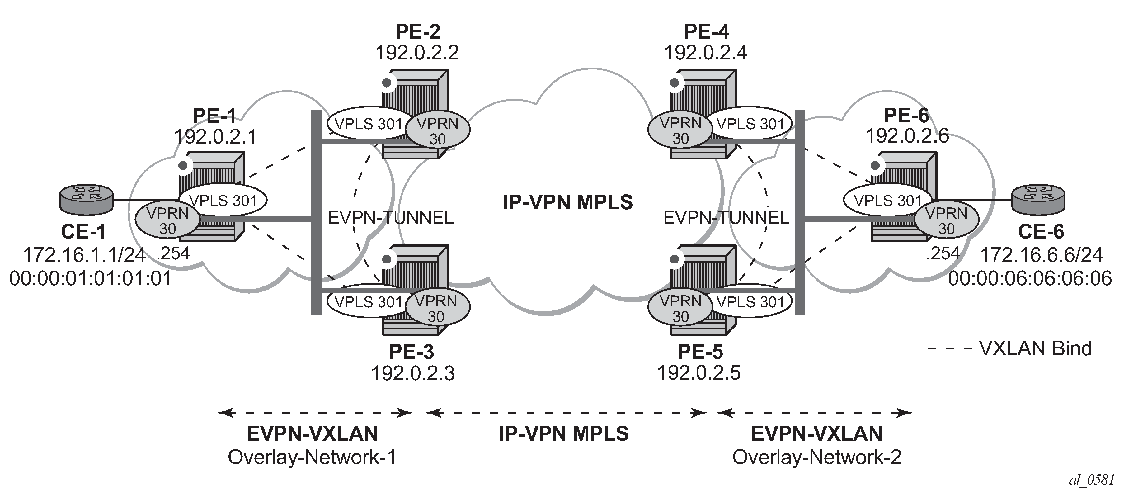
Compared to the preceding use case in EVPN-VXLAN for IRB backhaul R-VPLS services, in this case the R-VPLS connecting the IRB interfaces in Overlay-Network-1 (VPLS "evi-301") does not have any connected host. If that is the case, VPLS "evi-301" can be configured as an EVPN tunnel.
EVPN tunnels are enabled using the evpn-tunnel command under the R-VPLS interface configured on the VPRN. EVPN tunnels bring the following benefits to EVPN-VXLAN IRB backhaul R-VPLS services:
-
Easier and simpler provisioning of the tenant service: if an EVPN tunnel is configured in an IRB backhaul R-VPLS, there is no need to provision the IRB IP addresses in the VPRN. This makes the provisioning easier to automate and saves IP addresses from the tenant IP space.
-
Higher scalability of the IRB backhaul R-VPLS: if EVPN tunnels are enabled, BUM traffic is suppressed in the EVPN-VXLAN IRB backhaul R-VPLS service (it is not required). As a result, the number of VXLAN bindings in IRB backhaul R-VPLS services with EVPN tunnels can be much higher.
As an example, the VPRN "VPRN30" and VPLS "evi-301" configurations on PE-1, PE-2, and PE-3 are shown. Similar configurations are needed in PE-4, PE-5, and PE-6.
# on PE-1:
configure {
    service {
        vpls "evi-301" {
            admin-state enable
            service-id 301
            customer "1"
            vxlan {
                instance 1 {
                    vni 301
                }
            }
            routed-vpls {
            }
            bgp 1 {
                route-distinguisher "192.0.2.1:301"
                route-target {
                    export "target:64500:301"
                    import "target:64500:301"
                }
            }
            bgp-evpn {
                routes {
                    ip-prefix {
                        advertise true
                    }
                }
                vxlan 1 {
                    admin-state enable
                    vxlan-instance 1
                }
            }
        }
        vprn "VPRN30" {
            admin-state enable
            service-id 30
            customer "1"
            interface "int-PE-1-CE-1" {
                ipv4 {
                    primary {
                        address 172.16.1.254
                        prefix-length 24
                    }
                }
                sap 1/2/1:30 {
                }
            }
            interface "int-evi-301" {
                vpls "evi-301" {
                    evpn-tunnel {
                    }
                }
            }
        }
# on PE-2:
configure {
    service {
        vpls "evi-301" {
            admin-state enable
            service-id 301
            customer "1"
            vxlan {
                instance 1 {
                    vni 301
                }
            }
            routed-vpls {
            }
            bgp 1 {
                route-distinguisher "192.0.2.2:301"
                route-target {
                    export "target:64500:301"
                    import "target:64500:301"
                }
            }
            bgp-evpn {
                routes {
                    ip-prefix {
                        advertise true
                    }
                }
                vxlan 1 {
                    admin-state enable
                    vxlan-instance 1
                }
            }
        }
        vprn "VPRN30" {
            admin-state enable
            service-id 30
            customer "1"
            bgp-ipvpn {
                mpls {
                    admin-state enable
                    route-distinguisher "192.0.2.2:30"
                    vrf-target {
                        community "target:64500:30"
                    }
                    auto-bind-tunnel {
                        resolution filter
                        resolution-filter {
                            ldp true
                        }
                    }
                }
            }
            interface "int-evi-301" {
                vpls "evi-301" {
                    evpn-tunnel {
                    }
                }
            }
        }
# on PE-3:
configure {
    service {
        vpls "evi-301" {
            admin-state enable
            service-id 301
            customer "1"
            vxlan {
                instance 1 {
                    vni 301
                }
            }
            routed-vpls {
            }
            bgp 1 {
                route-distinguisher "192.0.2.3:301"
                route-target {
                    export "target:64500:301"
                    import "target:64500:301"
                }
            }
            bgp-evpn {
                routes {
                    ip-prefix {
                        advertise true
                    }
                }
                vxlan 1 {
                    admin-state enable
                    vxlan-instance 1
                }
            }
        }
        vprn "VPRN30" {
            admin-state enable
            service-id 30
            customer "1"
            bgp-ipvpn {
                mpls {
                    admin-state enable
                    route-distinguisher "192.0.2.3:30"
                    vrf-target {
                        community "target:64500:30"
                    }
                    auto-bind-tunnel {
                        resolution filter
                        resolution-filter {
                            ldp true
                        }
                    }
                }
            }
            interface "int-evi-301" {
                vpls "evi-301" {
                    evpn-tunnel {
                    }
                }
            }
        }
As shown in the preceding output, the configuration in the three nodes (PE-1/2/3) for VPLS "evi-301" and VPRN "VPRN30" is similar to the configuration of VPLS "evi-201" and VPRN "VPRN20" in the preceding scenario. When the evpn-tunnel command is added to the VPRN interface, there is no need to configure an IP interface address. The option evpn-tunnel can be enabled independently of routes>ip-prefix>advertise (although no route type 5 advertisements are sent when routes>ip-prefix>advertise false is configured).
A VPRN supports regular IRB backhaul R-VPLS services as well as EVPN tunnel R-VPLS services. A maximum of eight R-VPLS services with routes>ip-prefix>advertise enabled per VPRN is supported (in any combination of regular IRB R-VPLS or EVPN tunnel R-VPLS services). EVPN tunnel R-VPLS services do not support SAPs or SDP-bindings. No frames are flooded in an EVPN tunnel R-VPLS service, and, in fact no inclusive multicast routes are exchanged in R-VPLS services that are configured as EVPN tunnels.
The show service id vxlan destinations command for an R-VPLS service configured as an EVPN tunnel shows <egress VTEP, VNI> bindings excluded from Mcast, in other words, the VXLAN bindings are not used to flood BUM traffic:
[/]
A:admin@PE-2# show service id 301 vxlan destinations

===============================================================================
Egress VTEP, VNI
===============================================================================
Instance    VTEP Address                            Egress VNI  EvpnStatic Num
 Mcast       Oper State                              L2 PBR     SupBcasDom MACs
-------------------------------------------------------------------------------
1           192.0.2.1                               301         evpn       1
 -           Up                                      No          No
1           192.0.2.3                               301         evpn       1
 -           Up                                      No          No
-------------------------------------------------------------------------------
Number of Egress VTEP, VNI : 2
-------------------------------------------------------------------------------
===============================================================================

===============================================================================
BGP EVPN-VXLAN Ethernet Segment Dest
===============================================================================
Instance  Eth SegId                       Num. Macs     Last Change
-------------------------------------------------------------------------------
No Matching Entries
===============================================================================
The process followed upon receiving a route type 5 on a regular IRB R-VPLS interface (preceding scenario) differs from the one for an EVPN tunnel type (this scenario):
-
IRB backhaul R-VPLS VPRN interface:
-
When a route type 2 that includes an IP address is received and it becomes active, the MAC/IP information is added to the FDB and ARP tables. This can be checked with the show router 30 arp command and the show service id 301 fdb detail command.
-
When a route type 5 is received on (for instance) PE-2, and becomes active for the R-VPLS service, the IP prefix is added to the VPRN routing table regardless of the existence of a route type 2 that can resolve the GW IP address. If a packet is received from the WAN side and the IP lookup hits an entry for which the GW IP (IP next-hop) does not have an active ARP entry, the system will ARP to get the MAC. If the ARP is resolved but the MAC is unknown in the FDB table, the system floods the ARP message into the R-VPLS multicast list. Routes type 5 can be checked in the routing table with the show router 30 route-table command and the show router 30 fib 1 command.
-
-
EVPN tunnel R-VPLS VPRN interface:
-
When a route type 2 is received and becomes active, the MAC address is added to the FDB (only). This MAC address is normally a GW MAC address.
-
When a route type 5 is received on (for instance) PE-1, the system looks for the GW MAC address. The IP prefix is added to the VPRN routing table with next hop equal to EVPN-tunnel GW MAC; for example, ET-02:13:ff:00:00:6a is an EVPN tunnel with GW MAC 02:13:ff:00:00:6a. The GW MAC address is added from the GW MAC extended community sent along with the route type 5 for prefix 172.16.6.0/24. If a packet is received from CE-1 and the IP lookup hits an entry for which the next hop is an EVPN tunnel: GW MAC, the system looks up the GW MAC address in the FDB. Normally a route type 2 with the GW MAC address has already been received so that the GW MAC address has been added to the FDB. If the GW MAC address is not present in the FDB, the packet will be dropped.
-
The IP prefixes with GW MAC addresses as next hops for the setup in EVPN-VXLAN in EVPN-tunnel R-VPLS services are displayed in the show router 30 route-table command, as follows:
[/]
A:admin@PE-1# show router 30 route-table

===============================================================================
Route Table (Service: 30)
===============================================================================
Dest Prefix[Flags]                            Type    Proto     Age        Pref
      Next Hop[Interface Name]                                    Metric
-------------------------------------------------------------------------------
172.16.1.0/24                                 Local   Local     00h02m40s  0
       int-PE-1-CE-1                                                0
172.16.6.0/24                                 Remote  EVPN-IFF  00h00m36s  169
       int-evi-301 (ET-02:13:ff:00:00:6a)                           0
-------------------------------------------------------------------------------
No. of Routes: 2
Flags: n = Number of times nexthop is repeated
       B = BGP backup route available
       L = LFA nexthop available
       S = Sticky ECMP requested
===============================================================================
The same routing policies are applied on the core PEs to prevent loops; see Use of routing policies to avoid routing loops in redundant PEs.
The show service id 301 fdb detail command can be used to look for the forwarding information for a GW MAC address:
[/] A:admin@PE-1# show service id 301 fdb detail =============================================================================== Forwarding Database, Service 301 =============================================================================== ServId MAC Source-Identifier Type Last Change Transport:Tnl-Id Age ------------------------------------------------------------------------------- 301 02:0f:ff:00:00:6a cpm Intf 03/02/22 11:52:54 301 02:13:ff:00:00:6a vxlan-1: EvpnS:P 03/02/22 11:53:02 192.0.2.2:301 301 02:17:ff:00:00:6a vxlan-1: EvpnS:P 03/02/22 11:53:09 192.0.2.3:301 ------------------------------------------------------------------------------- No. of MAC Entries: 3 ------------------------------------------------------------------------------- Legend: L=Learned O=Oam P=Protected-MAC C=Conditional S=Static Lf=Leaf =============================================================================== -
IP prefix routes sent for EVPN tunnel R-VPLS services do not contain a GW IP address (the GW IP address is zero) but convey a GW MAC address that is used in the peer VPRN routing table. The following output shows PE-2’s VPRN "VPRN30" interface MAC address sent to PE-1:
[/]
A:admin@PE-2# show router 30 interface "int-evi-301" detail | match "MAC "
MAC Address      : 02:13:ff:00:00:6a    Mac Accounting    : Disabled
When routes>ip-prefix>advertise true is configured, PE-2 sends route type 5 messages to PE-1, as can be seen in the following BGP update for the route toward subnet 172.16.6.0/24 in overlay network 2, using the MAC address as GW MAC address:
# on PE-2:
configure {
    service {
        vpls "evi-301" {
            bgp-evpn {
                routes {
                    ip-prefix {
                        advertise true
                    }
                }
            }
221 2022/03/02 11:54:51.734 UTC MINOR: DEBUG #2001 Base Peer 1: 192.0.2.1
"Peer 1: 192.0.2.1: UPDATE
Peer 1: 192.0.2.1 - Send BGP UPDATE:
    Withdrawn Length = 0
    Total Path Attr Length = 90
    Flag: 0x90 Type: 14 Len: 45 Multiprotocol Reachable NLRI:
        Address Family EVPN
        NextHop len 4 NextHop 192.0.2.2
        Type: EVPN-IP-PREFIX Len: 34 RD: 192.0.2.2:301, tag: 0,
              ip_prefix: 172.16.6.0/24 gw_ip 0.0.0.0 Label: 301 (Raw Label: 0x12d)
    Flag: 0x40 Type: 1 Len: 1 Origin: 0
    Flag: 0x40 Type: 2 Len: 0 AS Path:
    Flag: 0x40 Type: 5 Len: 4 Local Preference: 100
    Flag: 0xc0 Type: 16 Len: 24 Extended Community:
        target:64500:301
        mac-nh:02:13:ff:00:00:6a
        bgp-tunnel-encap:VXLAN
"
In the routing table of VPRN "VPRN30" on PE-2, IP prefixes are shown with an EVPN tunnel next-hop (GW MAC) as opposed to an IP next-hop, therefore, the user may think that no ARP entries are consumed by VPRN "VPRN30". However, internal ARP entries are still consumed in VPRN "VPRN30". Although not shown in the show router 30 arp command, the summary option shows the consumption of internal ARP entries for EVPN.
[/]
A:admin@PE-2# show router 30 route-table

===============================================================================
Route Table (Service: 30)
===============================================================================
Dest Prefix[Flags]                            Type    Proto     Age        Pref
      Next Hop[Interface Name]                                    Metric
-------------------------------------------------------------------------------
172.16.1.0/24                                 Remote  EVPN-IFF  00h04m28s  169
       int-evi-301 (ET-02:0f:ff:00:00:6a)                           0
172.16.6.0/24                                 Remote  BGP VPN   00h02m40s  170
       192.0.2.4 (tunneled)                                         10
-------------------------------------------------------------------------------
No. of Routes: 2
Flags: n = Number of times nexthop is repeated
       B = BGP backup route available
       L = LFA nexthop available
       S = Sticky ECMP requested
===============================================================================
There are no entries in the ARP table:
[/]
A:admin@PE-2# show router 30 arp

===============================================================================
ARP Table (Service: 30)
===============================================================================
IP Address      MAC Address       Expiry    Type   Interface
-------------------------------------------------------------------------------
No Matching Entries Found
===============================================================================
One internal BGP-EVPN ARP entry is consumed, as can be seen as follows:
[/]
A:admin@PE-2# show router 30 arp summary

============================================================
ARP Table Summary (Service: 30)
============================================================
Local ARP Entries    : 1
Static ARP Entries   : 0
Dynamic ARP Entries  : 0
Managed ARP Entries  : 0
Internal ARP Entries : 0
BGP-EVPN ARP Entries : 1
------------------------------------------------------------
No. of ARP Entries   : 2
============================================================
The number of BGP-EVPN ARP entries in the show router 30 arp summary command matches the number of remote valid GW MAC addresses for VPRN "VPRN30".
Routing policies for IP prefixes in EVPN
Routing policies are supported for IP prefixes imported or exported through BGP EVPN. The default import and export behavior for IP prefixes in EVPN can be modified by using routing policies applied either at peer level (config>router>bgp>group/neighbor>import/export) or VPLS level (config>service>vpls>bgp>vsi-import/vsi-export).
When applying routing policies to control the distribution of prefixes between EVPN and IP-VPN, the user must take into account that both families are completely separated as far as BGP is concerned and that when prefixes from a family are imported in the RTM, the BGP attributes are lost to the other family. The use of tags allows the controlled distribution of prefixes across the two families.
Routing policies for egress EVPN routes illustrates how VPN-IPv4 routes are imported into the RTM and then passed onto EVPN for its own processing. VPN-IPv4 routes can be tagged at ingress and this tag is preserved throughout the RTM and EVPN processing so that the tag can be matched by the egress BGP routing policy. In this example, egress EVPN routes matching tag 10, are modified to add a site-of-origin (SOO) community origin:64500:1.
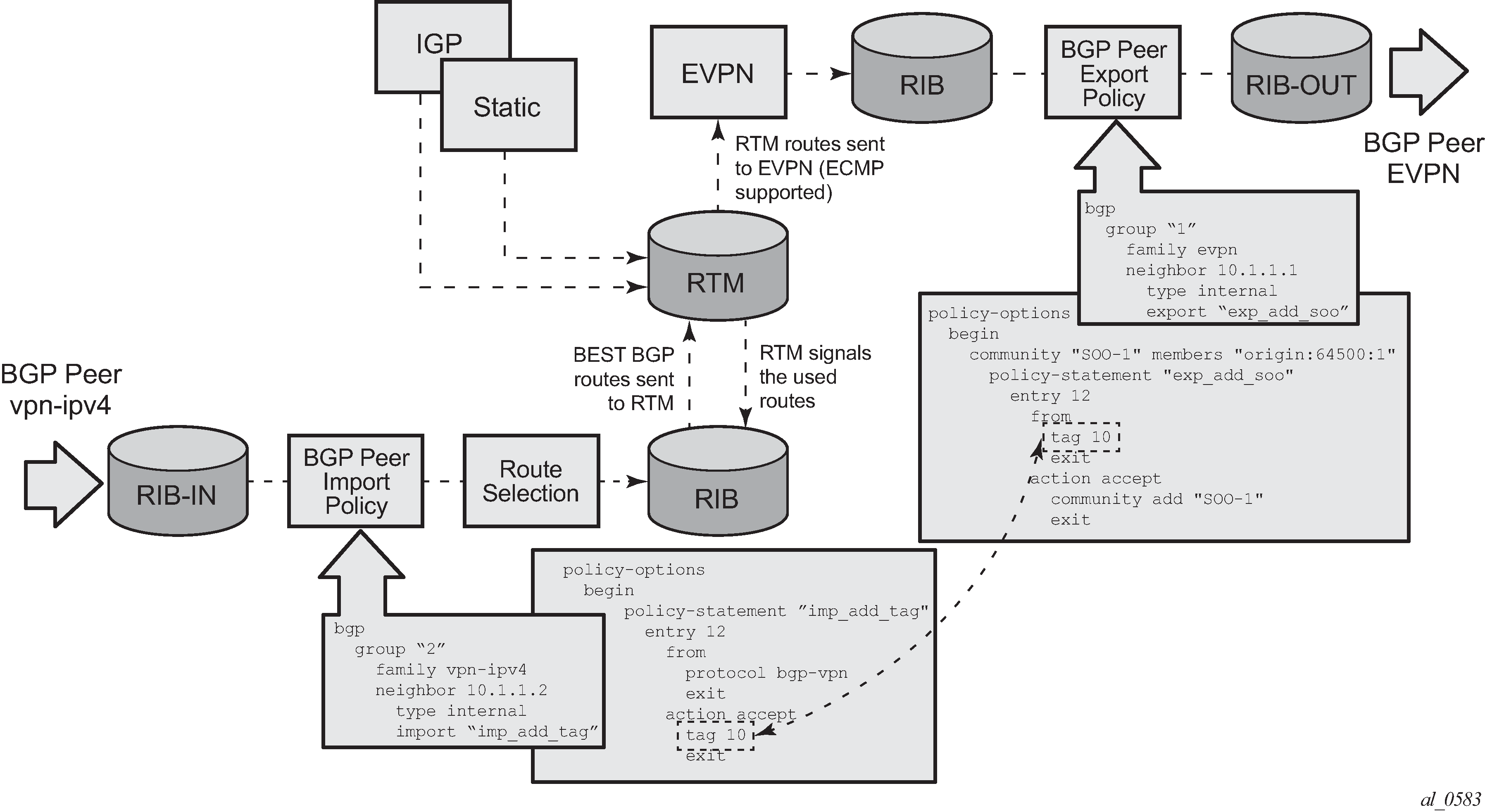
Policy tags can be used to match EVPN IP-prefixes that were learned not only from BGP VPN-IPv4 but also from other routing protocols.
*[ex:/configure policy-options policy-statement "test" entry 10 action]
A:admin@PE-1# tag ?

 tag (<number> | <string>)
 <number>  - <1..4294967295>
 <string>  - <1..32 characters>

    OSPF RIP or IS-IS tag applied to routes
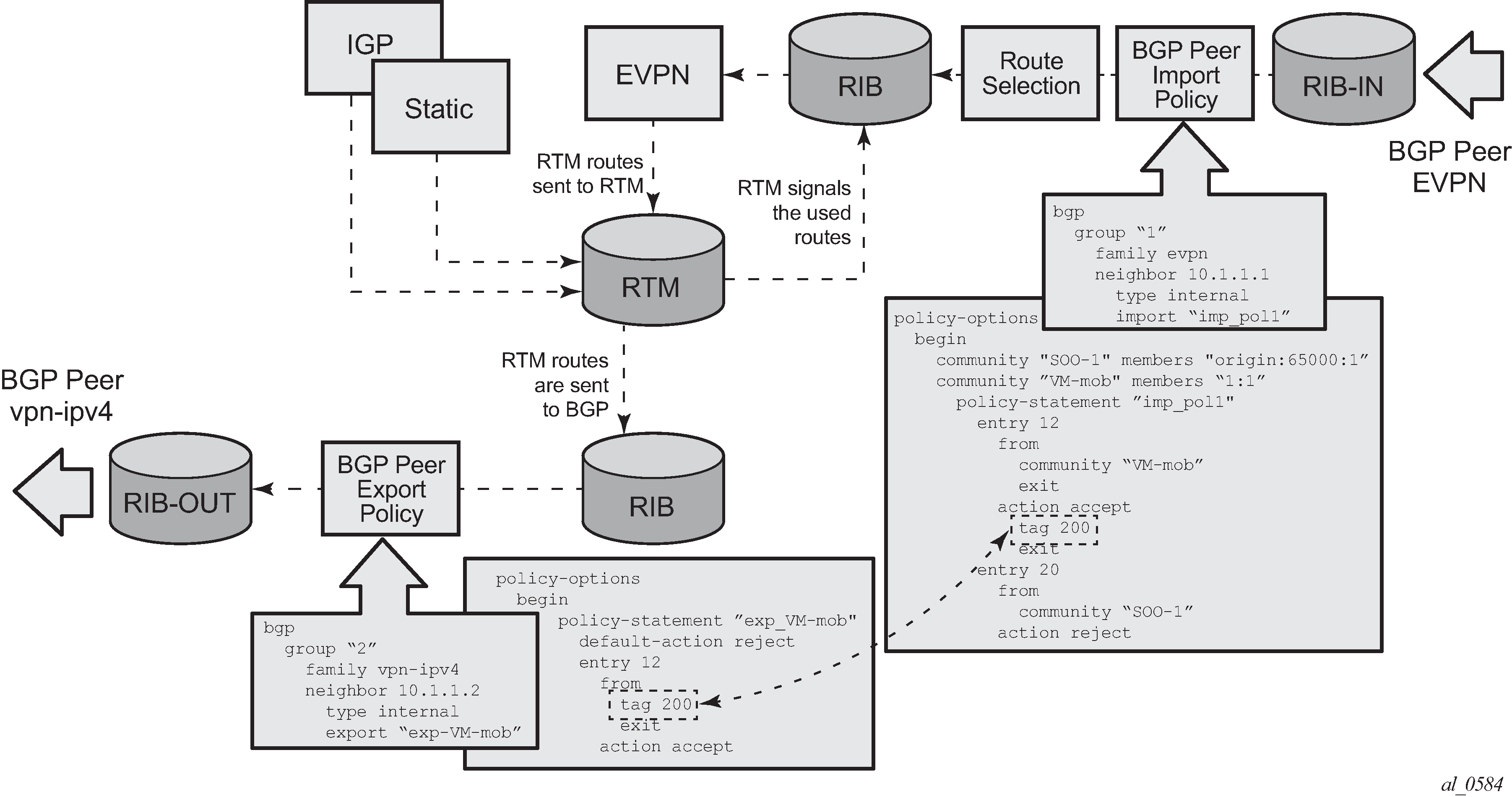
Routing policies for ingress EVPN routes illustrates the reverse workflow: routes imported from EVPN and exported from RTM to BGP VPN-IPv4. In this example, EVPN routes received with community VM-mob are tagged with tag 200. At the egress VPN-IPv4 peers, only the routes with tag 200 are advertised.
The preceding behavior and the use of tags is also valid for vsi-import and vsi-export policies. The behavior can be summarized in the following statements:
-
For EVPN prefix routes received and imported in RTM:
-
Routes can be matched on communities and tags can be added to them. This works at peer level or vsi-import level.
-
Well-known communities [no-export | no-export-subconfed | no-advertise] also require that the routing policies add a tag if the user wants to modify the behavior when exporting to BGP.
-
Routes can be matched based on family EVPN.
-
Routes cannot be matched on prefix list.
-
-
For exporting RTM to EVPN prefix routes:
-
Routes can be matched on tags and based on that, communities added, or routes accepted or rejected, and so on. This works at peer level or vsi-export level.
-
Tags can be added for static routes, RIP, OSPF, IS-IS, and BGP and then be matched in the vsi-export policy for EVPN IP-prefix route advertisement.
-
Tags cannot be added for direct routes.
-
Use of routing policies to avoid routing loops in redundant PEs
When redundant PE VPRN instances are connected to the same R-VPLS service (IRB backhaul or EVPN tunnel R-VPLS) with the routes>ip-prefix>advertise true command enabled, routing loops can occur in two different use cases:
-
Routing loop caused by EVPN and IP-VPN interaction in the RTM.
-
Routing loop caused by EVPN in parallel R-VPLS services.
Policy configuration examples for both cases are provided in the following sections.
Routing loop use-case 1: EVPN and IP-VPN interaction
This use case refers to scenarios with redundant PEs and VPRNs connected to the same R-VPLS with routes>ip-prefix>advertise true. The scenarios in EVPN-VXLAN for IRB backhaul R-VPLS services (EVPN-VXLAN for IRB Backhaul R-VPLS services) and EVPN-VXLAN in EVPN-tunnel R-VPLS services (EVPN-VXLAN in EVPN tunnel R-VPLS services) are examples of this use case. In both scenarios, the following process causes a routing loop:
-
PE-4 advertises IP prefix 172.16.6.0/24 with preference 170 (IP-VPN) to PE-2 and PE-3.
-
PE-2 and PE-3 import prefix 172.16.6.0/24 in the VPRN routing table. PE-2 re-advertises prefix 172.16.6.0/24 with preference 169 (EVPN) to PE-1 and PE-3; PE-3 re-advertises the IP prefix in EVPN to PE-1 and PE-2.
-
PE-2 and PE-3 already have the 172.16.6.0/24 prefix in the VPRN routing table with preference 170 (IP-VPN) but because the IP prefix from EVPN has a lower preference (169), the RTM installs the EVPN prefix in the VPRN routing table.
-
PE-2 advertises the EVPN-learned IP prefix 172.16.6.0/24 to all MP-BGP VPN-IPv4 peers, including PE-3; PE-3 advertises the prefix 172.16.6.0/24 to all MP-BGP VPN-IPv4 peers, including PE-2.
-
PE-2 receives the IP prefix 172.16.6.0/24 again from PE-3 and advertises it in EVPN again, creating a routing loop. The same thing happens in PE-3.
This routing loop also happens in traditional multi-homed IP-VPN scenarios where the PE-CE eBGP and MP-BGP VPN-IPv4/v6 protocols interact in the same VPRN RTM, with different router preferences. In either case (EVPN or eBGP interaction with MP-BGP) the issue can be solved by using routing policies and site-of-origin communities.
Routing policies are applied to PE-2 and PE-3 (also to PE-4 and PE-5) and allow the redundant PEs to reject their own generated routes to avoid the loops. These routing policies can be applied at vsi-import/export level or BGP group/neighbor level. The following output shows an example of routing policies applied at BGP neighbor level for PE-2 (similar policies are applied on PE-3, PE-4, and PE-5). Neighbor or group level policies are the preferred way in this kind of use case: a single set of policies is sufficient, as opposed to a set of policies per service (if the policies are applied at vsi-import or vsi-export level).
The following policies are applied in the BGP group or BGP neighbor context on PE-2:
# on PE-2:
configure {
    policy-options {
        community "SOO-PE-2" {
            member "origin:2:1" { }
        }
        community "SOO-PE-3" {
            member "origin:3:1" { }
        }
        policy-statement "add-SOO_on_export" {
            entry 10 {
                from {
                    tag 2
                }
                action {
                    action-type accept
                    community {
                        add ["SOO-PE-2"]
                    }
                }
            }
            entry 20 {
                from {
                    tag 3
                }
                action {
                    action-type accept
                    community {
                        add ["SOO-PE-3"]
                    }
                }
            }
        }
        policy-statement "reject_based_on_SOO" {
            entry 10 {
                from {
                    community {
                        name "SOO-PE-2"
                    }
                }
                action {
                    action-type reject
                }
            }
            entry 20 {
                from {
                    community {
                        name "SOO-PE-3"
                    }
                }
                action {
                    action-type reject
                }
            }
        }
        policy-statement "add-tag_to_bgp-evpn_routes" {
            entry 10 {
                from {
                    family [evpn]
                }
                action {
                    action-type accept
                    tag 2
                }
            }
        }
        policy-statement "add-tag_to_bgp-vpn_routes" {
            entry 10 {
                from {
                    protocol {
                        name [bgp-vpn]
                    }
                }
                action {
                    action-type accept
                    tag 2
                }
            }
        }
    }
    router "Base" {
        bgp {
            vpn-apply-export true
            vpn-apply-import true
            rapid-withdrawal true
            peer-ip-tracking true
            rapid-update {
                evpn true
            }
            group "DC" {
                peer-as 64500
                family {
                    vpn-ipv4 true
                    evpn true
                }
            }
            group "WAN" {
                peer-as 64500
                family {
                    vpn-ipv4 true
                }
                import {
                    policy ["add-tag_to_bgp-vpn_routes"]
                }
            }
            neighbor "192.0.2.1" {
                group "DC"
                import {
                    policy ["add-tag_to_bgp-evpn_routes"]
                }
            }
            neighbor "192.0.2.3" {
                group "DC"
                import {
                    policy ["reject_based_on_SOO"]
                }
                export {
                    policy ["add-SOO_on_export"]
                }
            }
            neighbor "192.0.2.4" {
                group "WAN"
            }
            neighbor "192.0.2.5" {
                group "WAN"
            }
EVPN and MP-BGP routes are tagged at import; on export, a site-of-origin community is added. Routes exchanged between the two redundant PEs are dropped if they are received by a PE with its own site-of-origin.
Routing loop use-case 2: EVPN in parallel R-VPLS services
If a VPRN is connected to more than one R-VPLS with routes>ip-prefix>advertise true configured, IP prefixes that belong to one R-VPLS are advertised into the other R-VPLS and vice versa. When redundant PEs are used, a routing loop will occur. EVPN in parallel R-VPLS services illustrates this use case. The example shows R-VPLS with an EVPN tunnel configuration, but the same routing loop occurs for regular IRB backhaul R-VPLS services.
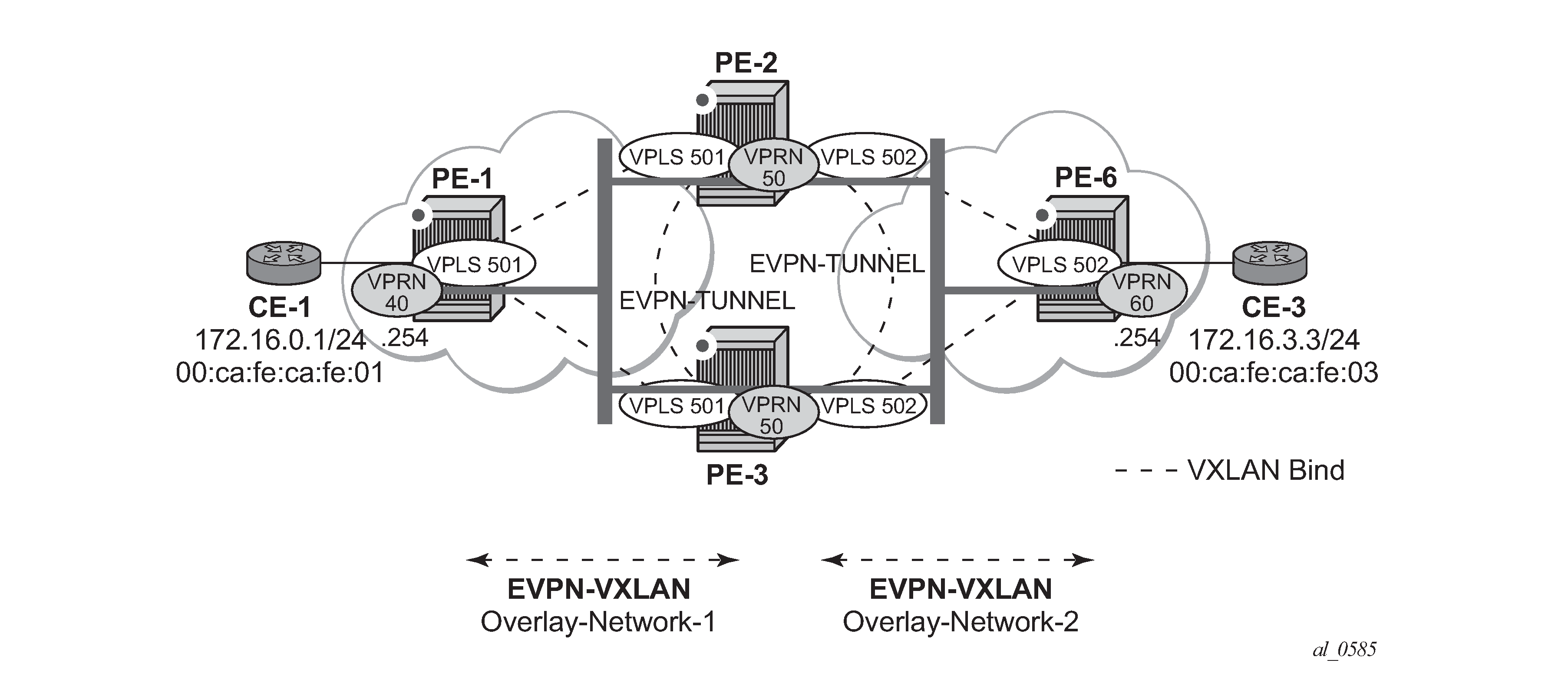
The configuration of VPRN "VPRN50" as well as VPLSs "evi-501" and "evi-502" and the required policies are as follows. For this use case, policies must be applied at vsi-import/export level because more granularity is required when modifying the imported/exported routes.
# on PE-2:
configure {
    policy-options {
        community "SOO-PE-2-RVPLS" {
            member "origin:2:11" { }
        }
        community "SOO-PE-3-RVPLS" {
            member "origin:3:11" { }
        }
        community "SOO_PE-3_RVPLS501" {
            member "origin:3:11" { }
            member "target:64500:501" { }
        }
        community "SOO_PE-3_RVPLS502" {
            member "origin:3:11" { }
            member "target:64500:502" { }
        }
        community "exp_RVPLS501" {
            member "origin:2:11" { }
            member "target:64500:501" { }
        }
        community "exp_RVPLS502" {
            member "origin:2:11" { }
            member "target:64500:502" { }
        }
        policy-statement "vsi-export-policy-501" {
            entry 10 {
                from {
                    tag 12
                }
                action {
                    action-type accept
                    community {
                        add ["SOO_PE-3_RVPLS501"]
                    }
                }
            }
            entry 20 {
                action {
                    action-type accept
                    community {
                        add ["exp_RVPLS501"]
                    }
                }
            }
        }
        policy-statement "vsi-export-policy-502" {
            entry 10 {
                from {
                    tag 12
                }
                action {
                    action-type accept
                    community {
                        add ["SOO_PE-3_RVPLS502"]
                    }
                }
            }
            entry 20 {
                action {
                    action-type accept
                    community {
                        add ["exp_RVPLS502"]
                    }
                }
            }
        }
        policy-statement "vsi-import-policy-501" {
            entry 10 {
                from {
                    community {
                        name "SOO-PE-2-RVPLS"
                    }
                }
                action {
                    action-type reject
                }
            }
            entry 20 {
                from {
                    community {
                        name "SOO_PE-3_RVPLS501"
                    }
                }
                action {
                    action-type accept
                    tag 12
                }
            }
            default-action {
                action-type accept
            }
        }
        policy-statement "vsi-import-policy-502" {
            entry 10 {
                from {
                    community {
                        name "SOO-PE-2-RVPLS"
                    }
                }
                action {
                    action-type reject
                }
            }
            entry 20 {
                from {
                    community {
                        name "SOO_PE-3_RVPLS502"
                    }
                }
                action {
                    action-type accept
                    tag 12
                }
            }
            default-action {
                action-type accept
            }
        }
    }
    service {
        vpls "evi-501" {
            admin-state enable
            service-id 501
            customer "1"
            vxlan {
                instance 1 {
                    vni 501
                }
            }
            routed-vpls {
            }
            bgp 1 {
                route-distinguisher "192.0.2.2:501"
                vsi-import ["vsi-import-policy-501"]
                vsi-export ["vsi-export-policy-501"]
            }
            bgp-evpn {
                routes {
                    ip-prefix {
                        advertise true
                    }
                }
                vxlan 1 {
                    admin-state enable
                    vxlan-instance 1
                }
            }
        }
        vpls "evi-502" {
            admin-state enable
            service-id 502
            customer "1"
            vxlan {
                instance 1 {
                    vni 502
                }
            }
            routed-vpls {
            }
            bgp 1 {
                route-distinguisher "192.0.2.2:502"
                vsi-import ["vsi-import-policy-502"]
                vsi-export ["vsi-export-policy-502"]
            }
            bgp-evpn {
                routes {
                    ip-prefix {
                        advertise true
                    }
                }
                vxlan 1 {
                    admin-state enable
                    vxlan-instance 1
                }
            }
        }
        vprn "VPRN50" {
            admin-state enable
            service-id 50
            customer "1"
            interface "int-evi-501" {
                vpls "evi-501" {
                    evpn-tunnel {
                    }
                }
            }
            interface "int-evi-502" {
                vpls "evi-502" {
                    evpn-tunnel {
                    }
                }
            }
        }
Troubleshooting and debug commands
For general information about EVPN and VXLAN troubleshooting and debug commands, see chapter EVPN for VXLAN Tunnels (Layer 2). The following information focuses on specific commands for Layer-3 applications.
When troubleshooting and operating an EVPN-VXLAN scenario with inter-subnet forwarding, it is important to check the IP prefixes and next-hops, as well as ARP tables and FDB tables:
-
show router <..> route-table
-
show router <..> arp
-
show service id <..> fdb detail
ICMP commands can also help checking the connectivity. When traceroute is used on EVPN-VXLAN in EVPN tunnel interfaces, EVPN tunnel interface hops in the traceroute commands are showing the VPRN loopback address or the other non EVPN-tunnel interface address. In VPRN services where all the interfaces are EVPN tunnels, ICMP packets fail until an IP address is configured. The following output shows a traceroute from VPRN "VPRN30" in PE-1 to CE-6 and from PE-2 to CE-1 (see EVPN-VXLAN in EVPN-tunnel R-VPLS services):
[/]
A:admin@PE-1# traceroute 172.16.6.6 router-instance "VPRN30"
traceroute to 172.16.6.6, 30 hops max, 40 byte packets
  1  0.0.0.0  * * *
  2  0.0.0.0  * * *
  3  172.16.6.254 (172.16.6.254)    4.79 ms  4.65 ms  4.80 ms
  4  172.16.6.6 (172.16.6.6)    5.32 ms  5.12 ms  4.86 ms
[/]
A:admin@PE-2# traceroute 172.16.1.1 router-instance "VPRN30"
traceroute to 172.16.1.1, 30 hops max, 0 byte packets
No route to destination. Address: 172.16.1.1, Router Instance:VPRN30
When troubleshooting R-VPLS services, specifically R-VPLS services configured as EVPN tunnels, the limit of peer PEs per EVPN tunnel service is much higher than for a regular R-VPLS service because the egress <VTEP, VNI> bindings do not have to be added to the multicast flooding list. For this reason, the following tools dump command has been added to check the consumed/total EVPN tunnel next hops. The number of EVPN tunnel next hops matches the number of remote GW MAC addresses per EVPN tunnel R-VPLS service.
[/]
A:admin@PE-1# tools dump service id 501 evpn usage

Evpn Tunnel Interface IP Next Hop: 2/8189
Finally, when troubleshooting EVPN routes and routing policies, the show router bgp routes evpn command and its filters can help:
-
Check that the expected routes are received, properly imported, and communities/tags added/replaced/removed.
-
Check that the expected routes are sent, properly exported, and communities added/replaced/removed.
Examples of EVPN IP prefix routes including communities and tags are the following.
[/]
A:admin@PE-2# show router bgp routes evpn ?

 auto-disc             - Display BGP EVPN Auto-Disc Routes
 eth-seg               - Display BGP EVPN Eth-Seg Routes
 incl-mcast            - Display BGP EVPN Inclusive-Mcast Routes
 ip-prefix             - Display BGP EVPN IPv4-Prefix Routes
 ipv6-prefix           - Display BGP EVPN IPv6-Prefix Routes
 mac                   - Display BGP EVPN Mac Routes
 mcast-join-synch      - Display BGP EVPN Mcast Join Sync Routes
 mcast-leave-synch     - Display BGP EVPN Mcast Leave Sync Routes
 smet                  - Display BGP EVPN Smet Routes
 spmsi-ad              - Display BGP EVPN Spmsi AD Routes
[/]
A:admin@PE-2# show router bgp routes evpn ip-prefix ?

 ip-prefix [[hunt-detail] <keyword>] [rd <string>] [prefix <string>]
           [community <string>] [tag <string>] [next-hop <string>]
           [aspath-regex <string>]

 [hunt-detail] <keyword>
 <keyword>  - (hunt|detail)

 [hunt-detail]         - keywords
 aspath-regex          - string '<1..80 characters>'
 community             - <as-number1:comm-val1>|<ext-comm>|, <well-known-comm>,
                         ext-comm - <type>:{<ip-address:comm-val1>|,
                         <as-number1:comm-val2>|,  <as-number2:comm-val1>},
                         as-number1 - [0..65535], comm-val1 - [0..65535],
                         type  - target|origin, ip-address - a.b.c.d,
                         comm-val2 - [0..4294967295], as-number2  - [0..4294967295],
                         well-known-comm - null|no-export|no-export-subconfed|,
                         no-advertise
 next-hop              - Attribute next-hop for ip-prefix
 prefix                - ip-prefix/ip-prefix-length
 rd                    - {<ip-addr:comm-val>|, <2byte-asnumber:ext-comm-val>|,
                         <4byte-asnumber:comm-val>}
 tag                   - Attribute tag for ip-prefix
Routing policy "vsi-export-policy-502" adds community "origin:2:11 target:64500:502" to the outgoing routes, as can be verified as follows:
[/]
A:admin@PE-2# show router bgp routes evpn ip-prefix hunt prefix 172.16.1.0/24
===============================================================================
 BGP Router ID:192.0.2.2        AS:64500       Local AS:64500
===============================================================================
 Legend -
 Status codes  : u - used, s - suppressed, h - history, d - decayed, * - valid
                 l - leaked, x - stale, > - best, b - backup, p - purge
 Origin codes  : i - IGP, e - EGP, ? - incomplete

===============================================================================
BGP EVPN IP-Prefix Routes
===============================================================================
-------------------------------------------------------------------------------
RIB In Entries
-------------------------------------------------------------------------------
---snip---
-------------------------------------------------------------------------------
RIB Out Entries
-------------------------------------------------------------------------------
Network        : n/a
Nexthop        : 192.0.2.2
Path Id        : None
To             : 192.0.2.1
Res. Nexthop   : n/a
Local Pref.    : 100                    Interface Name : NotAvailable
Aggregator AS  : None                   Aggregator     : None
Atomic Aggr.   : Not Atomic             MED            : None
AIGP Metric    : None                   IGP Cost       : n/a
Connector      : None
Community      : origin:2:11 target:64500:502
                 mac-nh:02:13:ff:00:01:33 bgp-tunnel-encap:VXLAN
Cluster        : No Cluster Members
Originator Id  : None                   Peer Router Id : 192.0.2.1
Origin         : IGP
AS-Path        : No As-Path
EVPN type      : IP-PREFIX
ESI            : n/a
Tag            : 0
Gateway Address: 02:13:ff:00:01:33
Prefix         : 172.16.1.0/24
Route Dist.    : 192.0.2.2:502
MPLS Label     : VNI 502
Route Tag      : 0
Neighbor-AS    : n/a
Orig Validation: N/A
Source Class   : 0                      Dest Class     : 0
---snip---
On PE-2, policy "add-tag_to_bgp-evpn_routes" adds route tag 2 to all BGP EVPN routes, as can be verified in the following output:
[/]
A:admin@PE-2# show router bgp routes evpn ip-prefix prefix 172.16.1.0/24 detail
===============================================================================
 BGP Router ID:192.0.2.2       AS:64500       Local AS:64500
===============================================================================
 Legend -
 Status codes  : u - used, s - suppressed, h - history, d - decayed, * - valid
                 l - leaked, x - stale, > - best, b - backup, p - purge
 Origin codes  : i - IGP, e - EGP, ? - incomplete

===============================================================================
BGP EVPN IP-Prefix Routes
===============================================================================
Original Attributes

Network        : n/a
Nexthop        : 192.0.2.1
Path Id        : None
From           : 192.0.2.1
Res. Nexthop   : 192.168.12.1
Local Pref.    : 100                    Interface Name : int-PE-2-PE-1
Aggregator AS  : None                   Aggregator     : None
Atomic Aggr.   : Not Atomic             MED            : None
AIGP Metric    : None                   IGP Cost       : 10
Connector      : None
Community      : target:64500:201 bgp-tunnel-encap:VXLAN
Cluster        : No Cluster Members
Originator Id  : None                   Peer Router Id : 192.0.2.1
Flags          : Used Valid Best IGP
Route Source   : Internal
AS-Path        : No As-Path
EVPN type      : IP-PREFIX
ESI            : n/a
Tag            : 0
Gateway Address: 172.16.0.1
Prefix         : 172.16.1.0/24
Route Dist.    : 192.0.2.1:201
MPLS Label     : VNI 201
Route Tag      : 0
Neighbor-AS    : n/a
Orig Validation: N/A
Source Class   : 0                      Dest Class     : 0
Add Paths Send : Default
Last Modified  : 00h04m30s

Modified Attributes

Network        : n/a
Nexthop        : 192.0.2.1
Path Id        : None
From           : 192.0.2.1
Res. Nexthop   : 192.168.12.1
Local Pref.    : 100                    Interface Name : int-PE-2-PE-1
Aggregator AS  : None                   Aggregator     : None
Atomic Aggr.   : Not Atomic             MED            : None
AIGP Metric    : None                   IGP Cost       : 10
Connector      : None
Community      : target:64500:201 bgp-tunnel-encap:VXLAN
Cluster        : No Cluster Members
Originator Id  : None                   Peer Router Id : 192.0.2.1
Flags          : Used Valid Best IGP
Route Source   : Internal
AS-Path        : No As-Path
EVPN type      : IP-PREFIX
ESI            : n/a
Tag            : 0
Gateway Address: 172.16.0.1
Prefix         : 172.16.1.0/24
Route Dist.    : 192.0.2.1:201
MPLS Label     : VNI 201
Route Tag      : 2
Neighbor-AS    : n/a
Orig Validation: N/A
Source Class   : 0                      Dest Class     : 0
Add Paths Send : Default
Last Modified  : 00h04m30s

-------------------------------------------------------------------------------
---snip---
Conclusion
SR OS supports not only the EVPN control plane for VXLAN tunnels in Layer 2 applications but also the simultaneous use of EVPN and VXLAN for VPN customers (tenants) with intra and inter-subnet connectivity requirements. R-VPLS services can be configured to provide default gateway connectivity to hosts, IRB backhaul connectivity to VPRN services, and EVPN tunnel connectivity to VPRN services.
When configured to do so, EVPN can advertise IP prefixes and interact with the VPRN RTM to propagate IP prefix connectivity between EVPN and other routing protocols in the VPRN, including IP-VPN. This example has shown how to configure R-VPLS services for all these functions, as well as how to configure routing policies for EVPN-based IP prefixes.