MAG-u resiliency
The Nokia cMAG-c supports a cMAG-c-driven MAG-u resiliency scheme. Learn about this resiliency scheme, the resiliency handling, and deployment use cases.
Terminology for MAG-u resiliency
- fate sharing group (FSG)
- An FSG is a group of sessions that stay together when moved between MAG-u nodes. This guarantees that any associated resources, such as ODSA allocated prefixes, are moved together with the sessions.
- active MAG-u
- In the scope of a single FSG, the active MAG-u is the MAG-u on which the sessions are created and that actively forwards traffic for those sessions.
- standby MAG-u
- In the scope of a single FSG, the standby MAG-u indicates the MAG-u that is ready to install sessions and forward traffic upon failure of the active MAG-u. Whether sessions are proactively created on this MAG-u depends on the chosen resiliency model.
- hot standby
- In the hot standby resiliency model, sessions are proactively created on a standby MAG-u. The standby MAG-u does not attract traffic but is ready to start forwarding as soon as the cMAG-c instructs it to do so.
- warm standby
-
In the warm standby resiliency model, sessions are created solely on the active MAG-u. Sessions on the standby (new active) MAG-u are only created after the active MAG-u fails.
Introduction to cMAG-c-driven MAG-u resiliency
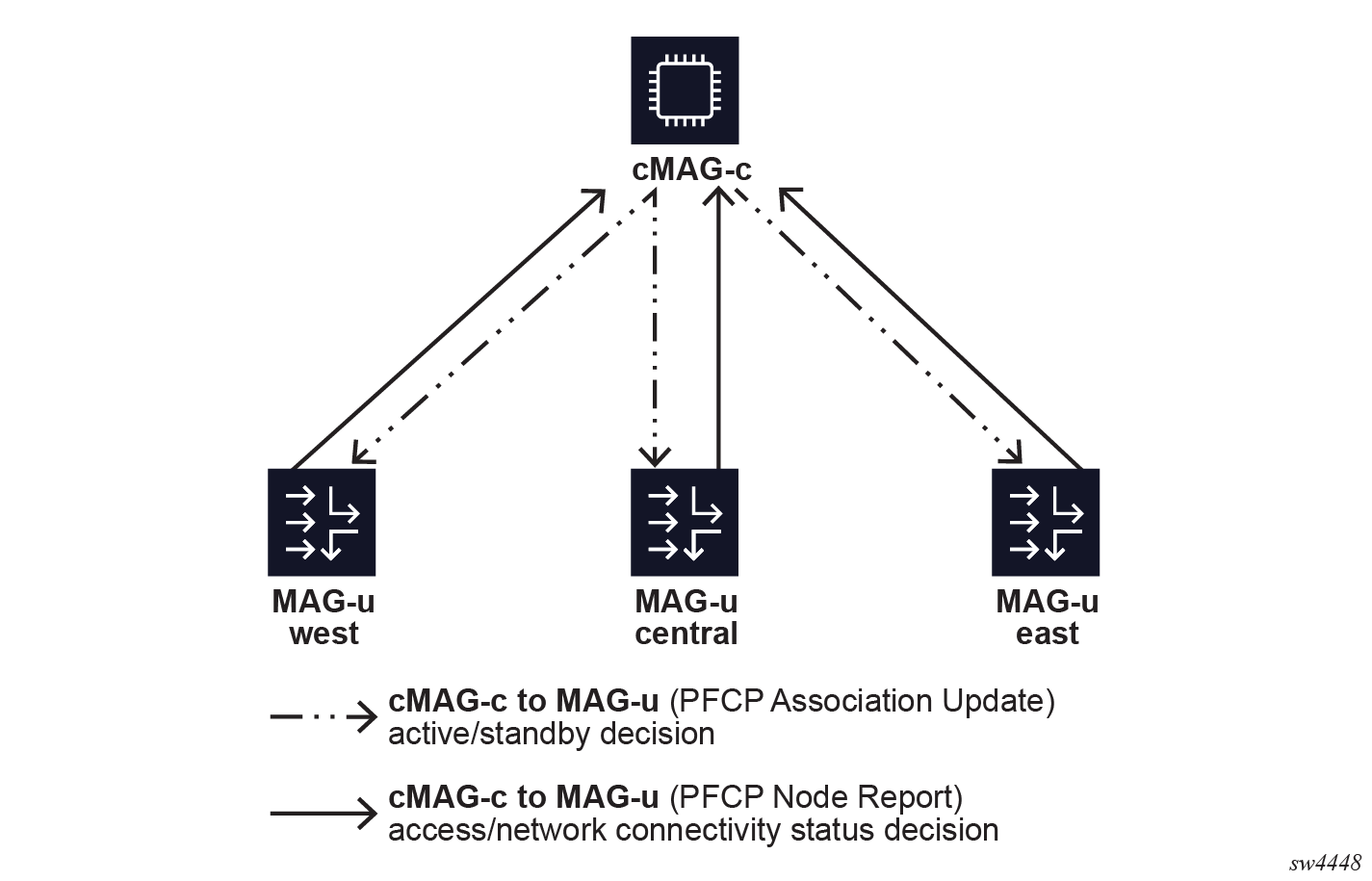
The Nokia cMAG-c supports a cMAG-c-driven MAG-u resiliency scheme. In this scheme, the cMAG-c selects the active and standby MAG-u nodes and the MAG-u nodes must follow this decision. The MAG-u nodes do not communicate directly to negotiate the active or standby role or to synchronize session state. Instead, each MAG-u sends its local status indicators to the cMAG-c; for example, whether it has full connectivity to the access network. The cMAG-c aggregates these status indicators from all MAG-u nodes and makes an informed decision that is sent to the MAG-u nodes. The PFCP node messages of the PFCP association between the MAG-u and cMAG-c that are already in place for session management carry the status indicators and informed decisions.
The following figure shows a high-level overview of communication for MAG-u resiliency.
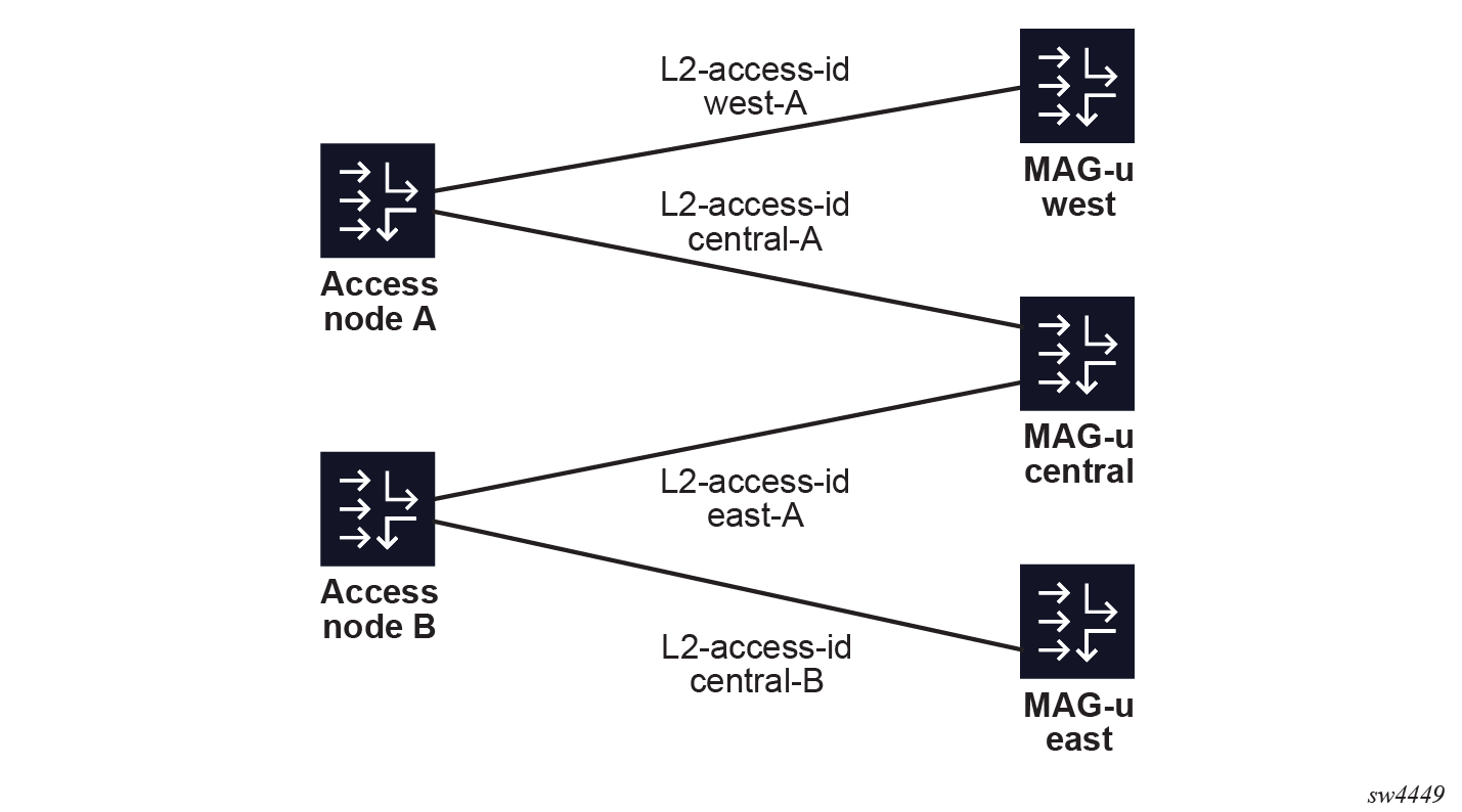
It is possible and often wanted that a MAG-u is active for a subset of the sessions and standby for another subset of the sessions. For example, when two MAG-u nodes are fully available, making both MAG-u nodes active for half of the sessions and standby for the other half of the sessions may be preferred. Similarly, two Layer 2 access IDs (ports) on the same MAG-u can be backed up by two different MAG-u nodes. The following figure shows the use case where the MAG-u "central" is backed up by both the MAG-u nodes "west" and "east" for two different Layer 2 access IDs.
To support all use cases, the cMAG-c assigns sessions to an FSG. The cMAG-c assigns the active or standby state to each FSG. The state applies to all sessions of the FSG, but not to any other session on the same MAG-u nodes. ODSA is also FSG-aware and allocates micro-nets on an FSG basis, instead of a MAG-u basis, to account for FSGs moving between MAG-u nodes.
Modeling a resilient MAG-u deployment using UP groups
The UP group configuration is a key component of the CUPS MAG-u resiliency. This configuration serves as a high-level description of the MAG-u access network so that the cMAG-c knows which MAG-u nodes are interconnected for MAG-u resiliency. Based on the UP group configuration, the cMAG-c automatically generates FSGs for the resiliency functionality. The UP group contains parameters to create the FSGs.
subscriber-management ref-points up groupAt the core of the UP group configuration is a list of MAG-u nodes. The PFCP Node ID IE as signaled during the PFCP association setup procedure identifies each MAG-u. The identifier can be either a name or an IP address. The MAG-u nodes that form the UP group are interconnected and MAG-u resiliency can occur between them.
Fate sharing group creation
The cMAG-c creates a single FSG per configured UP group. The following configuration for the FSG is provisioned via the UP group:
- reference to an FSG profileUse the following command to configure a reference to an FSG profile.
The profile contains detailed parameters on the resiliency behavior; for example, health calculation for each MAG-u. If no profile is provided in the UP group, the UP group behaves as if a profile with default parameters was applied.subscriber-management ref-points up group fsg-profile - preferred indicator
Per MAG-u, a flag indicates whether the MAG-u is active by preference. When the flag is set for a MAG-u, the FSG prefers this MAG-u to be active if all other parameters are equal.
- drain indicator
Per MAG-u, a flag indicates whether the MAG-u is in drain mode. When the flag is set for a MAG-u, the FSG avoids selecting this MAG-u as active. For example, this flag can be used before upgrading a MAG-u to achieve a graceful switchover.
Note: Changing the drain flag for an active MAG-u acts as a MAG-u reselection trigger for the linked FSGs. The cMAG-c moves the sessions after changing the configuration.
Fixed access with broadcast access
Fixed access sessions require the Layer 2 circuit (Layer 2 access ID and VLAN parameters) that is learned from incoming IBCP packets. In a resilient setting, the Layer 2 circuits can differ between the MAG-u nodes. For example, in Multiple backup MAG-us, Layer 2 access ID "central-A" on MAG-u "central" is backed up by Layer 2 access ID "west-A" on MAG-u "west". Because the cMAG-c cannot rely on the initial IBCP messages to learn all the Layer 2 access IDs, the IDs must be configured manually.
A single Layer 2 access ID can be configured per MAG-u in a UP group. When setting up a new session for this UP group, the cMAG-c learns the initial Layer 2 access ID from the incoming IBCP packet, but derives the Layer 2 access IDs for the other MAG-u nodes from the configuration. A UP group-level default can be configured to simplify cases where the Layer 2 access IDs are identically named. See Example for a 1:1 hot standby resiliency with an S-tag per access node for this use case.
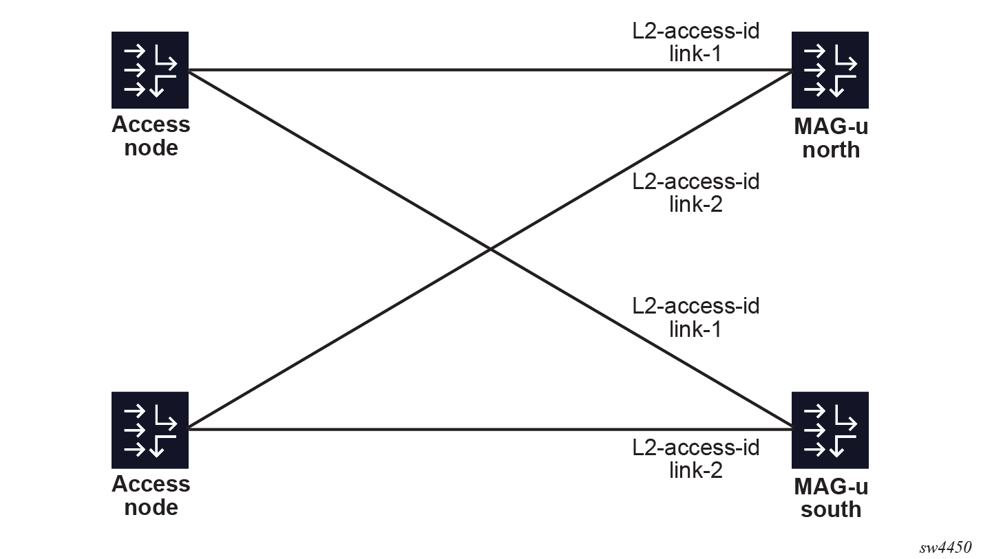
When all MAG-u nodes use identical Layer 2 access IDs, it is possible to list multiple Layer 2 access IDs per UP group at the group level to avoid creating multiple UP groups for each Layer 2 access ID. When this is configured, the MAG-u assumes that each Layer 2 access ID is backed up by the identically named Layer 2 access ID on other MAG-u nodes. The cMAG-c does not assume that there is one big broadcast domain shared between all ports and does not move sessions between differently named Layer 2 access IDs. The following figure shows a UP group that covers two Layer 2 access IDs, named "link-1" and "link2". The sessions on "link-1" cannot be backed up on "link-2" because "link-2" connects to another access node.
# info from running /subscriber-management ref-points up group demo
    subscriber-management {
        ref-points {
            up {
                group demo {
                    l2-access-id [
                        link-1
                        link-2
                    ]
                    peer north {
                    }
                    peer south {
                    }
                }
            }
        }
    }
Similarly, a VLAN range can be configured per MAG-u for both S-tags and C-tags. A UP group-level default is also available. The VLAN range configuration serves the following purposes:
- Split a single Layer 2 access ID in multiple FSGs and set a different preferred status on different MAG-u nodes. In stable conditions, this achieves active/active behavior where some sessions are active on one MAG-u while others are active on another MAG-u. See Example for a 1:1 hot standby resiliency with an S-tag per access node for this use case.
- Set different VLAN ranges on several MAG-u
nodes in more complex aggregation requirements. The cMAG-c automatically adjusts the VLANs learned from IBCP for each MAG-u
based on the difference between the start values of the VLAN ranges of each MAG-u. For
example, if MAG-u A is
configured with range 100 to 200, and MAG-u B
with range 500 to 600, a session with VLAN 150 on MAG-u A
automatically uses VLAN 550 on MAG-u B.
While the start values of the VLAN range can be different, all ranges must have an
equal size. For example, it is not possible to configure a range of 100 to 200 on
one MAG-u,
and 100 to 300 on another MAG-u in
the same UP group.WARNING: VLAN ranges with a different offset over more MAG-u nodes are an advanced use case and should be carefully validated against the deployed aggregation network. To avoid accidentally enabling different offsets when this functionality is not required, Nokia recommends only configuring a VLAN range on the UP group level.
The following subsections provide deployment use cases and example UP group configurations for the MAG-u resiliency concepts.
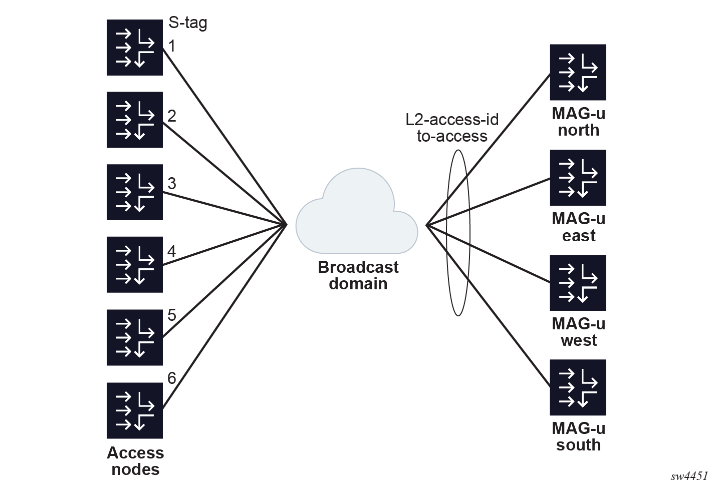
Example for a 1:1 hot standby resiliency with an S-tag per access node
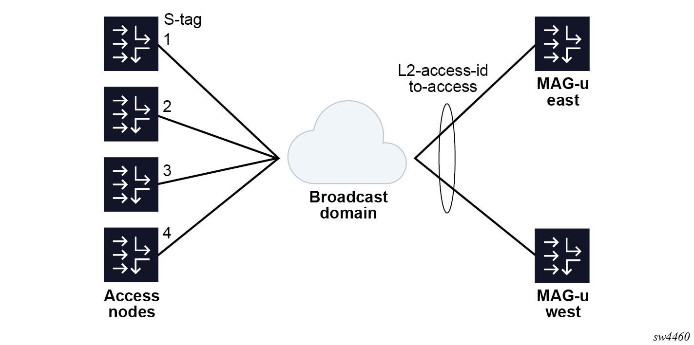
Four access nodes are connected to a pair of MAG-u nodes using a shared broadcast domain. To simplify Layer 2 forwarding, each access node is assigned a unique S-tag. The broadcast domain is connected to each MAG-u through an identically-named Layer 2 access ID on both MAG-u nodes. The cMAG-c makes abstraction of whether this connection is a port, LAG, BGP-VPLS, EVPN, or any similar construct.
- MD-CLI
configure service vpls capture-sap pfcp l2-access-id-alias - classic
CLI
configure service vpls sap pfcp l2-access-id-alias
- Split the Layer 2 access IDs based on S-tag ranges in two UP groups, each serving half of the access nodes.
- Configure a different MAG-u as preferred in each group to make the associated FSG active on the preferred MAG-u as long as that MAG-u is healthy.
# info from running /subscriber-management ref-points up group prefer-east
    subscriber-management {
        ref-points {
            up {
                group prefer-east {
                    l2-access-id [
                        to-access
                    ]
                    s-tag-range {
                        start 1
                        end 2
                    }
                    peer up-east {
                        preferred true
                    }
                    peer up-west {
                        preferred false
                    }
                }
            }
        }
    }
# info from running /subscriber-management ref-points up group prefer-west
    subscriber-management {
        ref-points {
            up {
                group prefer-west {
                    l2-access-id [
                        to-access
                    ]
                    s-tag-range {
                        start 3
                        end 4
                    }
                    peer up-east {
                        preferred false
                    }
                    peer up-west {
                        preferred true
                    }
                }
            }
        }
    }
The following figure shows an example for a 1:1 hot standby resiliency with an S-tag per access node.
Example for a per S-tag 1:1 hot standby resiliency with an S-tag per access node
This example extends the previous model with two access nodes and two MAG-u nodes.
Instead of splitting the MAG-u nodes such that there are two pairs of 1:1 MAG-u nodes, each S-tag range gets a different pair of standby MAG-u nodes as follows:
- S-tag 1 is backed by MAG-u "north" and "east"
- S-tag 2 is backed by MAG-u "east" and "west"
- S-tag 3 is backed by MAG-u "west" and "south"
- S-tag 4 is backed by MAG-u "south" and "north"
- S-tag 5 is backed by MAG-u "north" and "west"
- S-tag 6 is backed by MAG-u "east" and "south"
# info from running /subscriber-management ref-points up group s-tag-*
    subscriber-management {
        ref-points {
            up {
                group s-tag-1 {
                    l2-access-id [
                        to-access
                    ]
                    s-tag-range {
                        start 1
                        end 1
                    }
                    peer up-east {
                    }
                    peer up-north {
                    }
                }
                group s-tag-2 {
                    l2-access-id [
                        to-access
                    ]
                    s-tag-range {
                        start 2
                        end 2
                    }
                    peer up-east {
                    }
                    peer up-west {
                    }
                }
                group s-tag-3 {
                    l2-access-id [
                        to-access
                    ]
                    s-tag-range {
                        start 3
                        end 3
                    }
                    peer up-south {
                    }
                    peer up-west {
                    }
                }
                group s-tag-4 {
                    l2-access-id [
                        to-access
                    ]
                    s-tag-range {
                        start 4
                        end 4
                    }
                    peer up-north {
                    }
                    peer up-south {
                    }
                }
                group s-tag-5 {
                    l2-access-id [
                        to-access
                    ]
                    s-tag-range {
                        start 5
                        end 5
                    }
                    peer up-north {
                    }
                    peer up-west {
                    }
                }
                group s-tag-6 {
                    l2-access-id [
                        to-access
                    ]
                    s-tag-range {
                        start 6
                        end 6
                    }
                    peer up-east {
                    }
                    peer up-south {
                    }
                }
            }
        }
    }
The following figure shows an example of a per S-tag 1:1 hot standby resiliency.
- Two MAG-u nodes have two active FSGs.
- Two MAG-u nodes have one active FSG.
The difference between a MAG-u-level 1:1 model and an S-tag-level 1:1 model lies in the impact of multiple MAG-u failures. For example, compare the deployment where "north" and "south" back up each other and "east" and "west" back up each other without overlap. We assume each S-tag range is responsible for about 1/6th of the traffic.
- When two MAG-u nodes fail in the per-S-tag mode, it always impacts 1/6th of the traffic because each pair of MAG-u nodes is always uniquely responsible for one S-tag out of six. For example, if "north" and "south" fail, S-tag 4 completely fails.
- When two MAG-u nodes fail in the per-MAG-u mode, the impact depends on which nodes fail and that can either impact 0% or 50% of the traffic. For example, if both "north" and "west" fail, there is no lasting traffic impact because they do not back up each other. If both "south" and "north" fail, all traffic of the two S-tags covered by these MAG-u nodes fails.
This effect becomes stronger with more MAG-u nodes and S-tags to distribute. For example, in a model with 10 MAG-u nodes, the configuration can limit a failure of two MAG-u nodes to only affect about 2% of the traffic versus potentially 20% of the traffic if five 1:1 pairs are used.
This model makes the following assumptions on the aggregation model:
- A shared L2 broadcast domain must be available for all MAG-u nodes.
- A suitable granularity to differentiate UP groups must be available, such as S-tags in the example above.
- The MAG-u failures are unrelated. If the MAG-u failures happen in bulk (for example, because they are co-located), it can be better to make sure no co-located MAG-u nodes back up each other instead of to distribute resiliency as much as possible.
Fate sharing groups
Fate sharing groups (FSGs) are groups of sessions on which resiliency operations are performed. FSGs are automatically created based on configured UP groups. The FSGs are provisioned via the UP group.
When an FSG is created, the cMAG-c performs the following operations:
- Map new sessions to the FSG (see Session-to-FSG mapping).
- Determine traffic management parameters to attract traffic only to the MAG-u that serves the specific FSG (see Traffic steering parameters).
- Determine an aggregated health value for each MAG-u in the FSG.
- Upon MAG-u state and health changes, reselect an active and standby MAG-u for the FSG. Any change triggers this reselection, which guarantees that no state change is lost. In many cases, the cMAG-c selects the same active and standby MAG-u as before.
- Upon any active/standby change, update the FSG state on the MAG-u and, if necessary, update the session state on the MAG-u.
FSGs follow an intent-based processing model. The configuration specifies the conditions of resiliency behavior, expressing its intent. For example, the configuration specifies whether switchovers should be revertive and whether there is a preferred MAG-u. The cMAG-c monitors multiple parameters and, if necessary, changes active/standby decisions to better match the intent. The cMAG-c may execute multiple subsequent FSG changes to accomplish this.
Session-to-FSG mapping
When setting up a fixed access session, the cMAG-c uses the MAG-u ID, the Layer 2 access ID, and the VLAN ranges of the triggering IBCP packet to look up a UP group. If a UP group contains this set of parameters, the cMAG-c links the session automatically to the FSG created for that UP group.
Traffic steering parameters
- associates unique uplink and downlink parameters with each FSG
- signals those parameters to the MAG-u as part of creating the FSG when that MAG-u is selected as active or standby MAG-u for that specific FSG
ODSA allocates a unique set of per-FSG subnets (micro-nets). Because the subnets are unique per FSG, the active MAG-u can announce these subnets. To achieve the uniqueness, a session that is linked to an FSG passes the FSG as an allocation context to ODSA. ODSA automatically makes the micro-nets unique in that context.
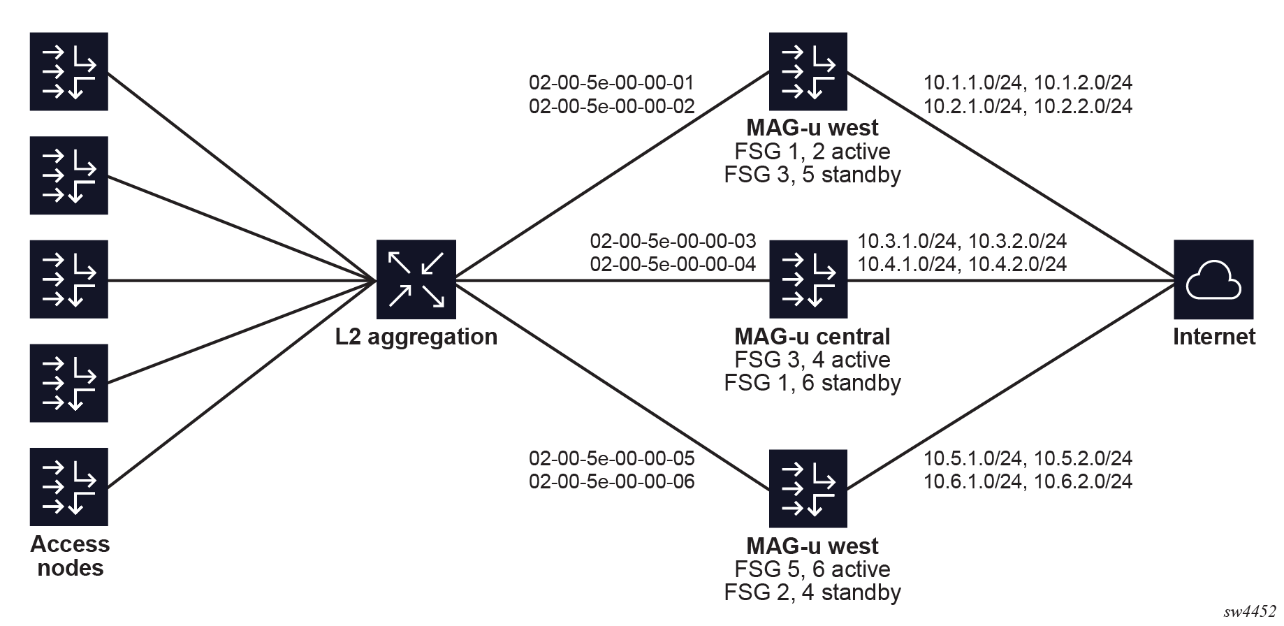
subscriber-management profiles fsg-profile mac-prefix-
FSG 1
MAC 02-00-5e-00-00-01
session subnet 10.1.1.0/24
session subnet 10.1.2.0/24
-
FSG 2
MAC 02-00-5e-00-00-02
session subnet 10.2.1.0/24
session subnet 10.2.2.0/24
-
FSG 3
MAC 02-00-5e-00-00-03
session subnet 10.3.1.0/24
session subnet 10.3.2.0/24
-
FSG 4
MAC 02-00-5e-00-00-04
session subnet 10.4.1.0/24
session subnet 10.4.2.0/24
-
FSG 5
MAC 02-00-5e-00-00-05
session subnet 10.5.1.0/24
session subnet 10.5.2.0/24
-
FSG 6
MAC 02-00-5e-00-00-06
session subnet 10.6.1.0/24
session subnet 10.6.2.0/24
MAG-u health determination
- When the PFCP path between the cMAG-c
and the MAG-u is down
or in headless mode, the health value is -1 (unavailable).Note: If a PFCP association is not set up, the MAG-u is operationally not part of the UP group and has no health.
- When any of the following commands is set to true, the health value is -1
(unavailable).
subscriber-management ref-points up group peer drain subscriber-management ref-points up peer drain - In all other cases, the health value is based on an aggregation of the operational statuses received from the MAG-u.
The MAG-u can signal the following operational status values to the cMAG-c:
- per Layer 2 access ID
A percentage value per Layer 2 access ID indicates the current forwarding capacity compared to the full forwarding capacity. For example, if the Layer 2 access ID represents a LAG with five members where one member failed, the expected capacity is 80%.
- per Layer 3 service (also known as network instance)
A binary connectivity status per Layer 3 service indicates whether the Layer 3 core network is reachable or not (connected or isolated). A Nokia MAG-u additionally augments this value with a percentage value to cover partial failures. The cMAG-c uses the more detailed percentage value if available; otherwise, the cMAG-c interprets the binary connectivity status as 100% for the connected state and 0% for the isolated state.
Not all status values of a single MAG-u apply to a specific FSG. For example, a UP group that only covers a single Layer 2 access ID is not impacted by any other Layer 2 access ID status. The cMAG-c determines the applicable status values as follows:
- By default, the cMAG-c
uses for the aggregation all Layer 2 access IDs
configured for the MAG-u in the
UP group. The following commands configure the Layer 2 access IDs.
subscriber-management ref-points up group peer l2-access-id subscriber-management ref-points up group l2-access-id - The cMAG-c
can exclude configured Layer 2 access IDs from the health calculation. This prevents
the cMAG-c
from automatically setting the health value to 0 if the MAG-u does not
or cannot provide a status value for Layer 2 access IDs. The following command
specifies whether to include Layer 2 access IDs and is true by
default.
subscriber-management profiles fsg-profile health-calculation include-l2-access-ids - The cMAG-c
tracks a list of configured network instances for health aggregation. The following
command configures the tracked network
instances.
subscriber-management profiles fsg-profile health-calculation network-instance
subscriber-management profiles fsg-profile health-calculation aggregation-modeThe options for the aggregation mode are:
- lowest
This mode sets the per-MAG-u health to the lowest value of any Layer 2 access ID and network instance value. A single failure aggressively decreases the health.
- average
This option sets the per-MAG-u health to the arithmetic mean of all Layer 2 access ID and network instance values. A single failure less aggressively impacts the health.
If the MAG-u does not signal a status value for a Layer 2 access ID or network instance that is configured to be tracked, the cMAG-c sets the status value for the respective Layer 2 access ID or network instance to 0%. Because the cMAG-c uses those values in the aggregation calculation, any missing status value sets the MAG-u health to 0% for an aggregation mode that is equal to lowest.
subscriber-management profiles fsg-profile health-calculation failure-thresholdThe cMAG-c maintains a special not-ready indicator for the current standby MAG-u. This indicator is set in the following conditions:
- The MAG-u changes to standby, independent of its previous state or health.
- The MAG-u health becomes unavailable (-1).
The cMAG-c removes the not-ready indicator each time an FSG change successfully completes (see Active/standby change or switchover) and the health of the MAG-u at that time is 0% or higher.
The cMAG-c avoids making a standby MAG-u with the not-ready indicator active unless it has no other choice; for example. when the PFCP association for the active MAG-u is released. This mechanism gives a failed or new standby MAG-u a chance to go through one FSG change sequence to reinstall all the hot standby sessions before it can be made active.
The cMAG-c can put a MAG-u in a lockout state for an FSG. When a MAG-u is in the lockout state, it cannot be made active or standby. Contrary to the other health values, the lockout state is intended to recover from hard failures where it is important that all FSG and related session state is removed from the MAG-u before it is considered active or standby again. See UP lockout for more information.
The following table provides an overview of the states that are kept for MAG-u nodes that have an active association and that are linked to at least one FSG.
| State | Description | Sources |
|---|---|---|
| health |
Value between 0% and 100% or the special value -1 (unavailable) Indicates the health of the MAG-u |
|
| failed indicator |
Indicator that considers the MAG-u failed if its health is less than the failure threshold Enables switchovers in more restrictive (for example, non-revertive) scenarios |
Based on the health state and the threshold configured with the
following
command.
|
| not-ready indicator |
Indicator on the standby MAG-u that does not have all hot standby sessions installed Kept until the standby MAG-u has installed the hot standby sessions |
Set for each new standby MAG-u or a standby MAG-u whose health becomes unavailable (-1). Removed after the first successful FSG change when the health is 0% or higher. |
| lockout |
Failure state in which the MAG-u cannot be made active or standby Kept until the MAG-u is no longer active or standby and a lockout timer has expired |
Applied automatically for multiple failure scenarios, see UP lockout for more information. |
Active/standby selection triggers
- recovery (for example, health up)
- degradation (for example, health down)
- starts a hold timer
- waits for the hold timer expiry
- triggers the active/standby selection
subscriber-management profiles fsg-profile active-standby-selection hold-off-on-recovery
subscriber-management profiles fsg-profile active-standby-selection hold-off-on-degradation- A health increase triggers a recovery hold timer of 5 s.
- A health decrease triggers the default degradation hold timer of 0 ms.
When a trigger occurs while an active/standby change is in progress, the cMAG-c ignores the hold timer of the new trigger and re-evaluates the active/standby selection as soon as the in-progress change completes.
The cMAG-c treats the following events as a recovery trigger:
- health increase; the cause of the health increase is irrelevant and may be because of headless recovery, change of the drain configuration of the MAG-u, or a MAG-u health report
- PFCP association setup, except if it is the first MAG-u set up for the FSG
- UP lockout removal
- intended FSG state not matching the current FSG state after an FSG event (see Active/standby change or switchover).
The cMAG-c treats the following events as a degradation trigger:
- health decrease
- PFCP association release, except if it is already the active or standby MAG-u
- UP lockout acts as a degradation trigger
The following exceptional triggers bypass the normal reselection mechanism because of their big impact:
- The setup of the first PFCP association for an FSG triggers an immediate reselection. The cMAG-c does not wait for the expiry of the recovery hold timer. If the PFCP association being set up is not the first association, it acts as a health increase and the cMAG-c starts the recovery hold timer.
- A PFCP association release for the active or standby MAG-u triggers an immediate reselection, bypassing any hold timers. If an active/standby change is already in progress, the ongoing change is completed first. A PFCP association release for any other MAG-u acts as a health decrease and the cMAG-c starts the degradation hold timer.
- If all MAG-u nodes become headless, the cMAG-c does not trigger any reselection. As soon as the first MAG-u
recovers from headless, the cMAG-c ignores the recovery hold timer but starts a timer based on the configured
path-management heartbeat intervals. The cMAG-c triggers reselection of all MAG-u
nodes when one of the following occurs:
- The timer based on the configured path-management heartbeat intervals expires.
- Five seconds have passed after the last MAG-u recovered.
Note: This mechanism ensures that after a full connectivity failure, all MAG-u nodes have time to recover the PFCP communication. It makes sure that the cMAG-c makes decisions based on the full set of recovered MAG-u nodes and not on the first recovered MAG-u nodes.
Active/standby selection
When an active/standby selection trigger occurs, the cMAG-c re-evaluates the selection of the active and standby MAG-u nodes for an FSG. If only one MAG-u with an active association is available, that specific MAG-u is always selected as the active MAG-u. Otherwise, both the active and standby MAG-u can be reselected.
Replacing the active MAG-u with the current standby MAG-u works in one of the following basic modes:
- revertive
The current standby MAG-u can be selected as the active MAG-u even if the active MAG-u did not fail. The conditions in which the standby MAG-u can become the active MAG-u are the same as the conditions to select the standby MAG-u. Additionally, the standby MAG-u cannot have the not-ready indicator set.
- non-revertive
The current standby MAG-u can only be selected as the active MAG-u if the PFCP association of the current active MAG-u is removed or if the MAG-u is considered failed (see MAG-u health determination), or if the MAG-u is in lockout state (see UP lockout). Otherwise, the current active MAG-u is always reselected as the active MAG-u.
subscriber-management profiles fsg-profile active-standby-selection active-change-without-failureThe following command options are available:
- always
The cMAG-c always uses the revertive mode.
- never
The cMAG-c always uses the non-revertive mode.
- initial-only
The cMAG-c uses the revertive behavior for a short period after the first MAG-u PFCP association for the FSG was set up. After that short period, the cMAG-c automatically switches to the non-revertive mode. This option is useful when the non-revertive mode is required but a predictable active/standby MAG-u is expected during startup of the MAG-u and cMAG-c; for example, to select the preferred MAG-u at startup. When the never option is set, the first MAG-u to come up is always selected as active (and that does not change), independent of its preferred state.
If the standby MAG-u becomes active, the active MAG-u automatically becomes standby. The cMAG-c takes no further action.
The cMAG-c selects a standby MAG-u independent of the revertive mode configuration.
Both the revertive active MAG-u and the standby MAG-u are selected using the following criteria. This is a fall-through list that stops as soon as there is only one MAG-u that meets all the criteria. Any MAG-u for which the PFCP association is down or which is in lockout is not considered, as follows:
- the MAG-u with the highest health (see MAG-u health determination)
- the preferred MAG-u
- the MAG-u
with the lowest number of sessions, simulated as if the FSG would move to that MAG-uNote: To avoid unnecessary FSG changes when the number of sessions on several MAG-u nodes is very similar, the cMAG-c applies a weight multiplier to the FSG session count when it simulates a move to a different MAG-u than the current one.
- the MAG-u with the lowest amount of FSGs, excluding the current FSG, with the goal to provide initial load balancing when no sessions are set up
- the current state of the MAG-u, where the current active MAG-u has priority over the current standby MAG-u that has priority over any backup MAG-u to avoid any unnecessary active or standby changes if all else is equal
- the MAG-u with the lowest IP used in PFCP signaling, with no specific goal other than to have a deterministic tiebreaker when all else is equal
If the result of the active/standby selection differs from the current active/standby selection, the cMAG-c initiates an active/standby change.
If the result of the active/standby selection is the same as the current active/standby selection, but the health of any MAG-u has changed from unavailable (-1) to 0% or higher, the cMAG-c also initiates an active/standby change.
Otherwise, the cMAG-c takes no further action.
Active/standby change or switchover
If the active/standby selection results in a new active or new standby MAG-u, the cMAG-c executes the change on the MAG-u nodes as follows:
-
The cMAG-c updates the PFCP FSG state on all involved MAG-u nodes.
The change procedure ends if the active MAG-u does not positively confirm. If the active MAG-u change times out or explicitly returns an error, the cMAG-c rolls back the changed FSG states and stops the active/standby change procedure.
Changes to other MAG-u nodes (for example, standby MAG-u nodes) may fail. This is even expected in some cases; for example, in 1:1 deployments where the previously active MAG-u has failed and becomes standby, the failed MAG-u is not expected to respond.
A MAG-u that explicitly rejects an explicit FSG update is put into lockout. This triggers a degradation reselection, which is handled as soon as the change is completed. See UP lockout for more information.
- When the active MAG-u confirms
the FSG change, the cMAG-c
starts updating the PFCP session states. The exact update for each session depends
on the change and the session resiliency model as follows:
- warm standby, active/standby switch
The cMAG-c establishes the session on the new active MAG-u and deletes it from the previous active MAG-u.
- warm standby, new standby MAG-u
No updates to the MAG-u nodes are needed.
- warm standby, health change only
No updates to the MAG-u nodes are needed.
- hot standby, active/standby switch
No updates to the MAG-u nodes are needed.
- hot standby, new standby MAG-u
The cMAG-c establishes the session on the new standby MAG-u and deletes it from the previous standby MAG-u if there was one.
- hot standby, health change only
This acts as a trigger to reinstall missing standby sessions on the standby MAG-u.
- warm standby, active/standby switch
- When the standby MAG-u confirms the FSG change, the cMAG-c sends a second FSG update message to the active MAG-u without changing anything. This can be done in parallel with the previous step. The second FSG update message may seem redundant, but is required to resolve a rare race condition in the GARP/ARP signaling for fixed access connections.
- When the session change procedure is completed, the cMAG-c signals any required FSG deletions to the MAG-u.
- When the change is completed, the cMAG-c evaluates whether the current active/standby state matches the expected active/standby state by running the selection logic again (see Active/standby selection). If the states do not match, the cMAG-c automatically triggers a recovery reselection and starts the recovery hold timer (see Active/standby selection triggers).
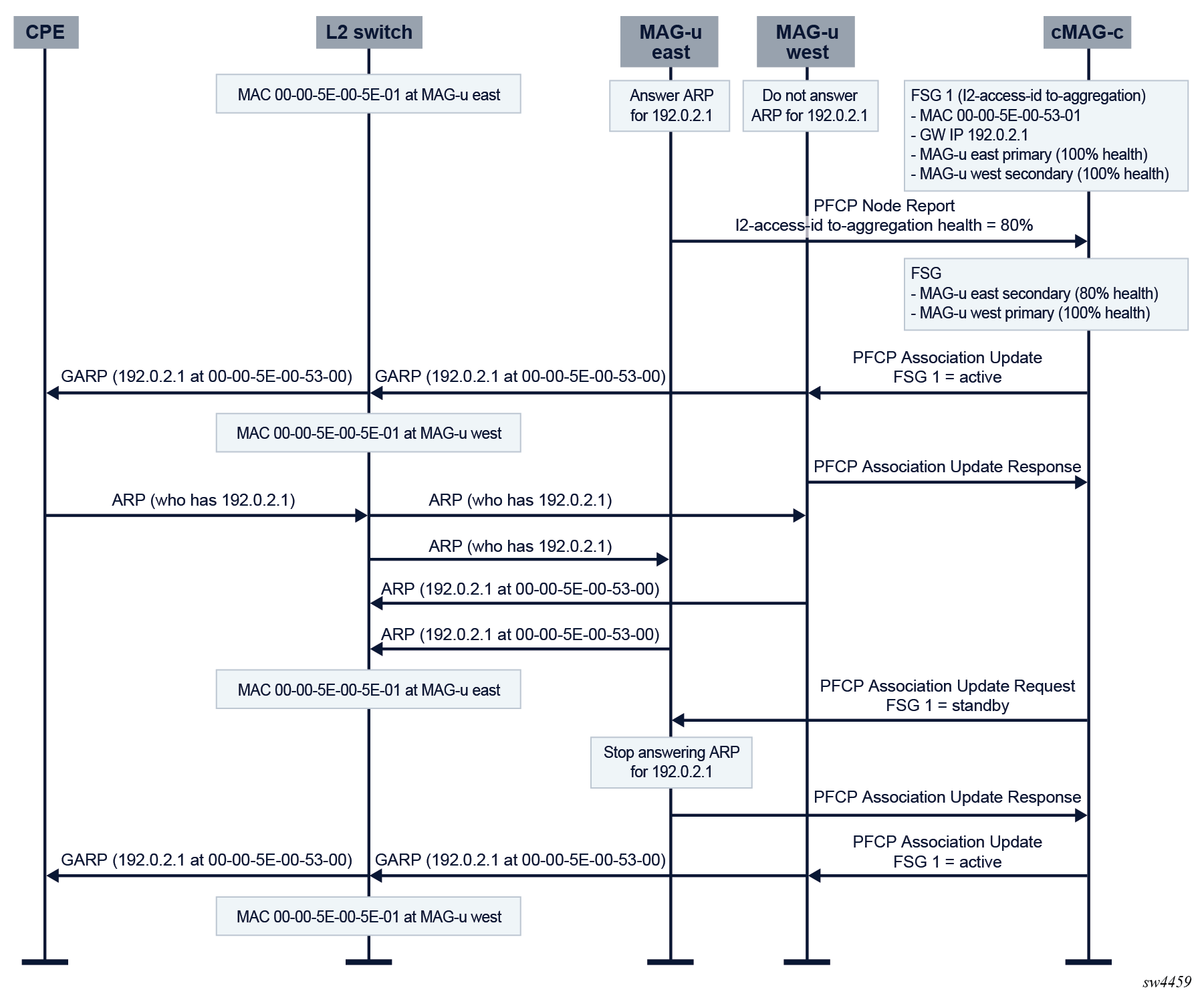
GARP/ARP race conditions
Fixed access connections use per-FSG MAC addresses to attract traffic (see Traffic steering parameters). Most Layer 2 aggregation switches keep a forwarding database (FDB) that points each gateway MAC address to the correct MAG-u to avoid broadcasting traffic. The FDBs are (amongst others) populated by snooping ARP and ND messages. To expedite updates of the FDBs during active/standby switchovers, the Nokia MAG-u generates a gratuitous ARP (GARP) message with the FSG MAC address when the FSG is signaled to become active. However, in a very exceptional case, a single GARP is not enough when the following conditions apply:
- The new standby MAG-u has not yet processed the message that asks it to become standby.
- A regular ARP is sent and broadcast as normal.
- Both MAG-u nodes answer, and the ARP response from the new standby MAG-u comes later than the ARP response of the new active MAG-u.
If the preceding conditions apply, the Layer 2 aggregation switch has a wrong FDB entry. Sending a second update to the new active MAG-u can act as a new GARP trigger to correct the situation. The following figure shows this case.
UP lockout
- an explicit FSG error from the MAG-u when signaling an FSG create, modify, or delete
- the path of a MAG-u going
down, in addition to setting its health to -1 (unavailable) (see MAG-u health determination)Note: This applies only to a full PFCP path down, and not to headless mode. For more information about the differences, see Headless mode. For more information about the interaction of MAG-u resiliency with headless mode, see Interaction with headless mode.
The cMAG-c treats a MAG-u going in lockout as a degradation trigger for the FSG (see Active/standby selection triggers). The cMAG-c attempts to remove the locked out MAG-u from being selected as either active or standby (see Active/standby selection).
subscriber-management profiles fsg-profile active-standby-selection failure-lockout- If the MAG-u is not active or standby for the FSG, the cMAG-c removes the lockout state and triggers a recovery reselection for the FSG.
- Otherwise, the cMAG-c restarts the lockout timer with a fixed value and takes no further action. This guarantees that the MAG-u is removed from the FSG at least one time and starts from a clean slate before it can be made active or standby again.
Warm and hot standby
Warm and hot standby in MAG-u resiliency is a per-session concept that defines how a session is handled on the standby MAG-u:
- Warm standby sessions are created on the standby MAG-u when the MAG-u becomes active. The sessions are not precreated on the standby MAG-u. This saves resources on the standby MAG-u, but it takes a significantly longer time during which there is no forwarding capability for those sessions.
- Hot standby sessions are precreated on the standby MAG-u. As soon as the MAG-u becomes active, it can start forwarding traffic for those sessions. While this consumes more resources than the standby MAG-u, it can offer significantly reduced forwarding loss during switchovers. Depending on the capabilities of the aggregation network, it may even be possible to achieve non-loss planned switchovers; for example, to seamlessly handle MAG-u upgrades.
For hot standby, any procedure that interacts with a MAG-u change (for example, a CoA with a QoS update) first applies the change on the active MAG-u. If the change succeeds, the procedure continues as usual and updates the standby MAG-u in parallel. In the unlikely event that only the standby MAG-u update fails, the cMAG-c does not fail the triggering procedure. Instead, it tries to reapply the update periodically in the background until the standby MAG-u is realigned with the active MAG-u. If this realignment is not resolved when the standby MAG-u becomes active, the cMAG-c does one final attempt to update the session state and, if not successful, locally removes the full session.
subscriber-management profiles fsg-profile default-standby-modeInteraction with headless mode
MAG-u resiliency is supported in combination with the MAG-u headless mode (see Headless mode). When a MAG-u becomes headless, its health becomes unavailable (-1) because the cMAG-c cannot differentiate between a MAG-u toward which communication failed (headless) or a MAG-u that completely failed. See MAG-u health determination for more information.
A MAG-u becoming headless acts as a trigger to perform a potential switchover from active to standby. A switchover cannot be signaled to the headless MAG-u, which operates on stale data. The Nokia MAG-u, by default, uses a heuristic process to determine whether to keep FSGs active or make them standby during headless operations. In rare cases, the MAG-u may keep an FSG active while the cMAG-c has successfully made another MAG-u active. As a result, there is an active/active forwarding situation in which both the headless and non-headless MAG-u nodes of an FSG have an active state. In this scenario, the following applies:
- Uplink QoS cannot always be guaranteed because traffic may switch from one MAG-u to the
other at any time. After headless recovery, the active/standby situation stabilizes
and traffic flows through only one MAG-u with
normal QoS guarantees.Note: Downlink QoS can still be guaranteed when the non-headless MAG-u announces routes with a higher preference than the headless MAG-u to consistently forward downlink traffic through the non-headless MAG-u. Additionally, if the access network updates its uplink forwarding based on downlink traffic, uplink traffic is forwarded through the non-headless MAG-u.
- Accounting reports may be off because traffic on the headless MAG-u is not counted. After headless recovery, the cMAG-c can fetch the missing statistics and the accounting is corrected.
- If there is unicast replication in the access network, these packets may end up being replicated also in the data network. However, this is extremely unlikely as the FSG MAC is most likely known at any point in time.
For more information about the headless heuristics and the downlink routing differentiation, see the 7750 SR and VSR BNG CUPS User Plane Function Guide.
- When a single MAG-u is headless, that MAG-u makes its FSGs standby and the cMAG-c makes the other MAG-u active. This results in an active/standby state as expected.
- When both MAG-u nodes are headless, for example, because of a networking issue at the cMAG-c, the FSG becomes standby on all MAG-u nodes and all traffic is dropped.