Fabric topology
The topological design of fabrics for data centers can vary widely. To accommodate diverse fabric structures, the Fabric Services System uses a modular, tiered approach to representing a fabric's hierarchical layers and their interconnections:
- Tier 1: leaf nodes, with edge-link connectivity
- Tier 2: spine nodes, which connect multiple leaf nodes together
- Tier 3: backbone nodes, which connect multiple fabrics together
- Tier 4: regional backbones, connecting backbone nodes together
This flexible, modular approach allows the Fabric Services System to model a wide range of topologies, grouping sets of leaves, spines, and backbone nodes in various ways and distributing connections between and within these groups in whichever way operators deem most efficient.
Flexible leaf/spine fabrics
At the base of the fabric hierarchy are the leaf nodes, providing downlink and access ports and connected together by one or more spine nodes.
A single data center fabric could include many such collections of leaf nodes, each with their own set of connecting spine nodes. But regardless of their number, an individual flexible leaf/spine structure is the basic building block of a fabric.
When you create a flexible leaf/spine fabric, you specify the number of leaf nodes and spine nodes; the system then proposes an initial topology in which all leaf nodes are linked to all spine nodes.
A simple flexible leaf/spine fabric topology shows a simple representation of a flexible leaf/spine topology, with a pair of leaf nodes (Tier 1) at the bottom of the figure. Each leaf node is linked to both of the spine nodes (Tier 2) at the top of the figure, but not to each other.
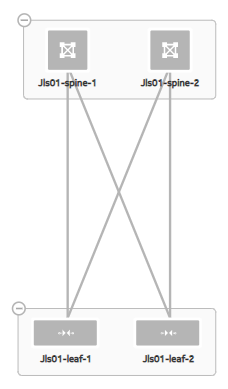
It is possible to design a fabric in which these connections are designed more selectively; for example, a particular set of spine nodes in the fabric could be connected only with particular sets of leaf nodes. But initially, the system proposes a fully connected default design that you can then modify if required.
eBGP peering for PE-CE links: learned route preference
Eventually links are created between leaf nodes and customer equipment; these are PE-CE links. When using eBGP to create such links, multiple paths may present themselves.
The Nokia certified flexible leaf/spine template
The Nokia template for a Flexible Leaf Spine fabric uses the following default values:
|
Parameter |
Template default value |
|---|---|
|
Spine type |
Chassis |
|
T1 layer uplink speed |
G100 |
|
Edge link speed |
G25 |
|
Tier one oversubscription |
1:3 |
|
Tier two oversubscription |
1:1 |
There are many more parameters that can be set for a fabric intent; this table shows only those that are governed by the flexible leaf/spine template.
Backbone fabrics
When a data center is composed of two or more flexible leaf/spine fabrics, these fabrics may need to communicate with each other to distribute traffic and share application workloads between them. You may also want to ensure that existing flexible leaf/spine fabrics use a single exit point to communicate with external networks.
The purpose of the backbone fabric is to provide the point of interconnection and shared egress for one or more flexible leaf/spine fabrics.
When you create a backbone fabric intent, you choose the node type to function (singly or more likely in groups) as the backbone, and then select the set of member flexible leaf/spine fabrics that the backbone fabric connects.
For this reason, you must create and deploy the participating flexible leaf/spine fabrics first, and then add the backbone fabric that connects them. Only fabrics in a Deployed state are eligible for selection and attachment to a new backbone fabric intent.
It is always possible to update the design of the backbone fabric intent to add more fully-deployed flexible leaf/spine fabrics as the data center fabric grows.
For the purpose of flexibility, the system supports the creation of a backbone fabric with only a single member flexible leaf/spine fabric. Such a design may be warranted if the backbone node provides capabilities that the spine nodes cannot. Or, such a fabric may be a forward-looking design that adds the backbone layer in anticipation of additional flexible leaf/spine fabrics to be added in the future.
When you create a backbone fabric intent and select its member flexible leaf/spine fabrics, there is an implicit change to each of those member flexible leaf/spine fabrics that adds the uplink from the spine node to the new backbone node.
For this reason, when you design a backbone fabric intent, the system automatically creates an updated version of each flexible leaf/spine fabric intent that includes this new uplink. When you deploy the backbone intent, the system first deploys the backbone fabric itself; and then the system deploys each of the updated flexible leaf/spine fabric intents to create the uplink to the new backbone.
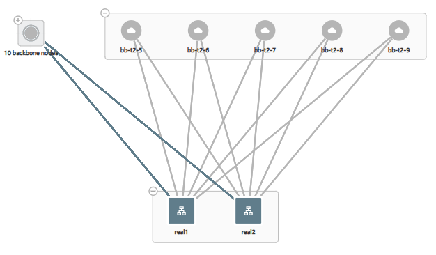
An example of a backbone topology shows a simple representation of a backbone fabric topology. Fifteen backbone nodes (Tier 3) separated into two groups each connect with two fabrics including their own leaves and spines (Tier 2 and Tier 1). Each flexible leaf/spine fabric is represented here as a single, collective icon.
Border leaf
A leaf node can also serve as a backbone node; in this case, it is a "border leaf" node; "leaf" because it can carry EVPN workloads like other leaves, but "border" because unlike other leaf nodes, it communicates with the external network.
Because the node must be capable of capable of carrying EVPN traffic in its role as a leaf node, only EVPN-capable hardware can serve as a border leaf node. This is reflected in the smaller list of hardware options when you select the node type for a border leaf backbone node.
The Nokia certified backbone template
The Nokia template for a backbone fabric uses the following default values:
Parameter |
Template default value |
|---|---|
Node type |
7250 IXR-6 |
Oversubscription |
1:3 |
There are many more parameters that can be set for a fabric intent; this table shows only those that are governed by the backbone template.