Procedure 9-2.2: Add new Alcatel-Lucent 1665 DMX node to BLSR
Important!
This is not a standalone procedure. Perform this procedure only as directed by Procedure 9-2: Add new Alcatel-Lucent 1665 DMX node to network.
Steps
Important!
This procedure assumes that the new Alcatel-Lucent 1665 DMX shelf has been equipped with the required circuit packs, software has been installed, and the shelf has passed the looped transmission tests. If not, refer to Chapter 5, Node turnup procedures.
A new Alcatel-Lucent 1665 DMX node may be added to a bidirectional line switched ring (BLSR) using the following:
A BLSR supports up to 16 nodes.
Complete the following steps to add a new Alcatel-Lucent 1665 DMX node to an OC-48/192 BLSR.
1 |
From the System View menu at a node in the OC-48/192 BLSR,
| ||
2 |
Important! For BLSR applications, the port Application parameter must be provisioned 2F BLSR. Up to 15 BLSR protection groups may be supported by a single network element when the Main slots are equipped with Very Large Fabric LNW59, LNW82, or LNW504 OLIU circuit packs. From the System View menu at the new node, select Configuration → Equipment to access the required ports and provision the port parameters according to the work instructions. Result: The system reports a default K-bytes alarm. Reference: Procedure 4-4: Provision OLIU circuit packs/ports for service | ||
3 |
Select View → Equipment to access the required ports and verify that the ports were provisioned correctly. | ||
4 |
From the system view at the new node,
| ||
5 |
From the System View menu at the new node,
| ||
6 |
Important! The LAPD Role parameter must be provisioned differently at each end of an optical span. For example, if the LAPD Role parameter is provisioned to user-side at one end of an optical span, then the LAPD Role parameter must be provisioned network-side at the other end of the optical span. From the System View menu at the new node,
Result: The system reports inconsistent DCC values and section DCC channel failed alarms. These alarms clear when the new node is connected to BLSR. Reference: Procedure 6-4: Provision DCC terminations | ||
7 |
From the System View menu at the new node, select View → DCC Terminations, verify that the DCC terminations were provisioned correctly and click Close. | ||
8 |
If the new node is added to the BLSR using the Main OLIU circuit packs, determine from either the Network Operations Center (NOC) or the work instructions the synchronization for the new node. If required, select Configuration → Timing/Sync and provision the synchronization parameters according to the work instructions or office records. Reference: Procedure 6-5: Network Element synchronization provisioning | ||
9 |
Determine from either the Network Operations Center (NOC) or the work instructions all the other nodes in the existing ring. Verify through the NOC all existing cross-connections that exist on the adjacent nodes to where the new node will be located. Also, note the source or destination, cross-connection type (for example, 2F BLSR add/drop, 1-way), and cross-connection rate (for example, STS1, STS3c). These will be pass-through cross-connections at the new node. Important! It may be helpful to make a sketch of the network to visualize the required pass-through cross-connections at the new node. To verify the cross-connections, at the adjacent West node select View → Cross-Connections. On the left side of the screen, select the required circuit pack and click Select. Record the Src (source tributary AID), Src NE Name (source network element name) Type, Rate, Dest (destination tributary AID), Dest NE Name (destination network element name), and CKT ID (circuit ID) of the cross-connections that result in traffic directly to and/or from the other adjacent node. These will be pass-through cross-connections at the new node. | ||
10 |
| ||
11 |
If VT1.5/STS-N pass-through cross-connections are not provisioned at the new node, service interruptions can occur. Pass-through cross-connections must be provisioned to support existing traffic on the ring through the new node. At the new node, enter the required VT1.5/STS-N pass-through cross-connections (based on the cross-connection information retrieved in Step 9) by selecting Configuration → Cross-Connections → Create a New Cross-Connection. | ||
12 |
At each node in the BLSR, verify that no BLSR protection switches are present, select View → Rolling Events. Under the line reading RTRV-COND-ALL determine if any protection switches are displayed. Remove all BLSR protection switches before continuing with this procedure. Reference: Alcatel-Lucent 1850 Transport Service Switch (TSS-5) Alarm Messages and Trouble Clearing Guide, 365-372-402 | ||
13 |
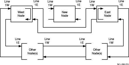
Important! The Force to Protection, Ring switch may cause transmission hits (less than 60 ms). Perform the following: (Refer to the following figure.)

Legend: Line 1W: Line 1W (West port) is the port in slot 1 of the 2F BLSR protection group (for example, Main-1 or FN-A-1). Line 1E: Line 1E (East port) is the port in slot 2 of the 2F BLSR protection group (for example, Main-2 or FN-A-2). | ||
14 |
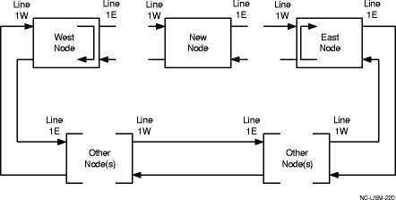
Removal of wrong fiber connections will result in a service interruption. Ensure that you remove only the fiber connections for the optical span being discontinued. Perform the following: (Refer to the following figure.)

Legend: Line 1W: Line 1W (West port) is the port in slot 1 of the 2F BLSR protection group (for example, Main-1 or FN-A-1). Line 1E: Line 1E (East port) is the port in slot 2 of the 2F BLSR protection group (for example, Main-2 or FN-A-2). | ||
15 |
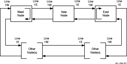
Perform the following: (Refer to the following figure.)
Refer to Procedure 14-4: Perform connection and verification of optical facility. 
Legend: Line 1W: Line 1W (West port) is the port in slot 1 of the 2F BLSR protection group (for example, Main-1 or FN-A-1). Line 1E: Line 1E (East port) is the port in slot 2 of the 2F BLSR protection group (for example, Main-2 or FN-A-2). | ||
16 |
Important! As the ring is connected, nodes automatically communicate with each other using the data communications channel (DCC) and build a ring map. If successful, automatic ring discovery builds a ring map at each node and the Ring Discovery in Progress condition clears. If unsuccessful, the ring map is not complete and alarms are reported. If automatic ring discovery is enabled, wait until the Ring Discovery in Progress condition clears. If other alarms/conditions are reported, refer to the Alcatel-Lucent 1665 Data Multiplexer (DMX) Alarm Messages and Trouble Clearing Guide, 365-372-302 and clear the alarms/conditions. | ||
17 |
From the System View menu at the new node, select Administration → OSI Neighbor Map and verify that the new node is connected to the required adjacent nodes. Important! If the report indicates wrong (or no) fiber connections and DCC-related alarms are reported, select View → DCC Terminations to obtain the View DCC Termination report and verify that the DCC terminations are provisioned correctly. If required, check fiber integrity and verify the node NSAP address is correct using the Administration → View NE Administration command. | ||
18 |
If required at the new node, select View → Timing/Sync and verify the operational synchronization mode of the new node. If the Timing Mode is holdover, check that the incoming timing references are connected. Also check Mode Switching (NA, revertive, or nonrevertive). If timing inputs are used, click the Timing Input Ports tab and check the Input and Output Format. | ||
19 |
If Automatic Ring Discovery is disabled (that is, manual ring discovery), activate the manual ring maps at the existing nodes in the network. Otherwise, continue with the next step. Select Configuration → Activate Manual Ring Map. Select the required Ring ID and click Select. Result: A dialog box appears asking you to confirm activating the manual ring map. Click OK. The inactive manual ring map is now activated. | ||
20 |
If the work instructions specify that the Auto Squelch Map parameter should be Manual at the new node, select Configuration → Equipment to access the required 2F BLSR protection group and provision the Auto Squelch Map parameter to Manual. | ||
21 |
Perform the following:
Important! The Clear switch may cause transmission hits (less than 60 ms). Wait for alarms to clear. | ||
22 |
From the System View menu at the East and West nodes,
| ||
23 |
At the new node and the adjacent nodes, click the Alarm List button and verify that no alarms are present. If required, clear any alarms that are present. Reference: Alcatel-Lucent 1665 Data Multiplexer (DMX) Alarm Messages and Trouble Clearing Guide, 365-372-302 | ||
24 |
Important! Establishing service requires that the proper slots in each terminating node be properly equipped with the correct circuit pack(s) for the type of service being established. It also requires numerous cross-connections in each of the nodes representing the path of the required service. Additionally, transmission tests should be performed to verify the continuity and quality of the established circuit. The new node is now ready for initial service to be established. Reference: End of steps |