Procedure 12-14: Upgrade OC-3 or OC-12 UPSR to a Alcatel-Lucent 1665 DMX OC-48/192 UPSR
 Overview
Use this procedure to perform an in-service upgrade of an existing DDM-2000 OC-3 or OC-12 UPSR, refer to Figure 12-2, Initial configuration for upgrade, to a Alcatel-Lucent 1665 DMX OC-48/192 UPSR. This procedure establishes a final configuration, refer to Figure 12-8, Final configuration in upgrade sequence, with the Alcatel-Lucent 1665 DMX OC-48/192 UPSR serving as a backbone ring for the subtending OC-3/12 ring.
 Privilege level
 Before you begin
Prior to performing this procedure:
-
Refer to Laser safety and Electrostatic discharge information in Chapter 1, Safety.
-
Notify the maintenance center of these planned upgrade activities and that alarms will be generated.
-
At each DDM-2000 OC-3 or OC-12 UPSR node, verify that no alarms, lockouts, loopbacks, or switches are present. Refer to the DDM-2000 User Service Manual (USM) if you need additional instruction. Any existing alarms must be cleared before starting this procedure.
-
This procedure is used to update a DDM-2000 OC-3/12 UPSR to a Alcatel-Lucent 1665 DMX OC-48/192 UPSR. It is assumed that the fiber being used in the current OC-3/12 ring will be used to build the new Alcatel-Lucent 1665 DMX UPSR.
-
With minor changes, this procedure may also be used to move VT1.5 service onto an existing OC-48/192 ring. The fiber connecting the OC-48/192 nodes at each site would already be connected and the OC-48/192 ring would already be carrying service.
-
This procedure uses an existing 3 node DDM-2000 OC-3/12 ring as an example for the OC-3/12 to OC-48/192 ring upgrade. See Figure 12-2, Initial configuration for upgrade. Other OC-3/12 network upgrades are possible and can be done using this procedure with minor modifications. Local procedures will have to be written, using the concepts of this procedure, to upgrade the particular configuration that you have.
-
This procedure assumes that a Alcatel-Lucent 1665 DMX has been installed and equipped, refer to Procedure 5-1: Equip new Alcatel-Lucent 1665 Data Multiplexer for Add/Drop Multiplexer (ADM) applications, at each existing OC-3/12 shelf location. The Alcatel-Lucent 1665 DMX shelf must be equipped with Main OLIUs and OC-3/12 OLIUs (in the Function Group or Growth slots being used to connect to the DDM-2000).
-
The application parameter of the OC-3/12 interfaces on the Alcatel-Lucent 1665 DMX must be set to 0x1 (Release 2 and earlier) or UPSR in Release 3 or later.
Note that in Release 3 or later, the 0X1 application parameter is no longer valid, and you have to use the UPSR application parameter for this configuration. A new parameter has been added to the cross-connection command to accomplish the function of 0X1 application. The new cross-connection parameter is channel application (chappl), with a value of UNSWITCHED.
-
TARP Release 15 or later ring software must be installed on the DDM-2000 shelves.
-
You may also contact Alcatel-Lucent to perform this in-service upgrade. Experienced Alcatel-Lucent installers will help you plan and execute the network upgrade. For more information, contact your Alcatel-Lucent Account Representative.
Steps
Complete the following steps to convert an in-service OC-3/12 UPSR to a Alcatel-Lucent 1665 DMX OC-48/192 UPSR.
1 |
Reference Figure 12-2, Initial configuration for upgrade as the starting point for this procedure. Figure 12-2: Initial configuration for upgrade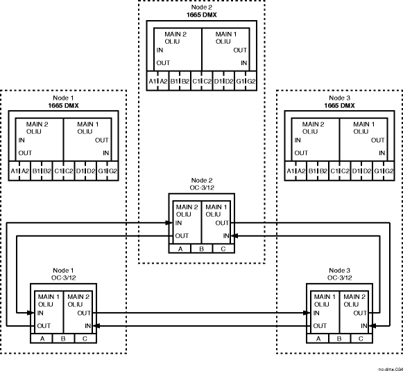 |
2 |
At each Alcatel-Lucent 1665 DMX node, connect the PC and establish a WaveStar® CIT session. Reference: Procedure 14-2: Connect Personal Computer (PC) and establish WaveStar® CIT session |
3 |
At each Alcatel-Lucent 1665 DMX node, select Configuration → DCC Terminations to verify/set Network Side/User Side parameters at each end of the optical span being established. Refer to the DDM-2000 user manual to verify/set NS/US parameters for this configuration. Note that if the default settings were not changed in the DDM-2000 ring configuration and the default settings are retained in the Function or Growth slots of the Alcatel-Lucent 1665 DMX node, no changes should be required. Important! The requirement is that one end of the optical fiber connection must be set to Network-Side and the other end must be set to User-Side. |
4 |
Refer to office records and verify that no duplicate TID settings exist among the existing network nodes and the new network nodes. Important! If duplicate TIDs exist, they must be resolved before continuing. As appropriate, refer to Procedure 7-11: Set/change system TID to change a Alcatel-Lucent 1665 DMX TID. Or, to the User Service Manual of the OC-3/12 subtending shelf. If you need additional instructions to help you complete this step on the DDM-2000 NEs, refer to the DDM-2000 documentation. |
5 |
At the Alcatel-Lucent 1665 DMX Nodes (1, 2, and 3 in this example) select Configuration → Provision to verify/set the Application parameter to 0x1 (Release 2 and earlier) or UPSR (Release 3 and later) for the OC-3 or OC-12 interfaces that are being used for this single-homed configuration. Reference: Procedure 4-4: Provision OLIU circuit packs/ports for service |
6 |
At each of the Alcatel-Lucent 1665 DMX host nodes (nodes 1, 2, and 3 in this example), determine and provision the add/drop cross-connections to support each single-homed OC-3 or OC-12 node. From the System View menu, select Configuration → Cross-Connections to start the Cross-Connection Wizard. Refer to Procedure 10-8: Make single-homed cross-connections. Important! Refer to the OLIU circuit pack descriptions in the descriptive chapters of this document to find the cross-connection capacities for Virtual Tributaries (VTs) for the OLIU circuit packs in the Alcatel-Lucent 1665 DMX. Any channels that are presently in service or cross-connected in the existing DDM-2000 ring must be cross-connected to the single-homed Function or Growth group OLIUs in the Alcatel-Lucent 1665 DMX nodes. In the case of a VT1.5 signal, the same STS-1 may be cross-connected to the OC-3/12 shelves at several Alcatel-Lucent 1665 DMX nodes until the STS-1 signal reaches its capacity of 28 VT1.5 signals. In Release 3 or later, note that the single-homed cross-connections to the DDM-2000 shelves must be cross-connected in the Alcatel-Lucent 1665 DMX from the main OLIUs to the Function or Growth OLIUs using the cross-connection parameter of chappl=UNSWITCHED. The connection between the DDM-2000 and Alcatel-Lucent 1665 DMX is a single-homed connection. In single-homed connections, the Function Group slot A1, B1, C1, D1, or Growth slot G1 OLIU in the Alcatel-Lucent 1665 DMX host shelf connects to the M1 OLIU at the first DDM-2000 shelf from the Alcatel-Lucent 1665 DMX host shelf. M2 OLIU at the first DDM-2000 shelf connects to Function Group slot A2, B2, C2, D2, or Growth slot G2 OLIU in the Alcatel-Lucent 1665 DMX host shelf. This procedure establishes the ring configuration starting from the Alcatel-Lucent 1665 DMX host node to the far-end DDM-2000 shelf and back to the host node. |
7 |
At each Alcatel-Lucent 1665 DMX shelf, determine the channels to be pass-through cross-connected in the Alcatel-Lucent 1665 DMX. Select Configuration → Cross-Connections at each required Alcatel-Lucent 1665 DMX shelf to make all required pass-through cross-connections for the previously selected channels. Important! At each Alcatel-Lucent 1665 DMX node in the ring, pass-through cross-connections must be made for each channel that is carrying traffic and that has not been cross-connected to a circuit pack in a Function or Growth slot in that Alcatel-Lucent 1665 DMX node. Critical or Major alarms will be generated if pass-through cross-connections are not made on each required Alcatel-Lucent 1665 DMX shelf in the ring. Note that in the examples in this procedure there are no pass-through Alcatel-Lucent 1665 DMX nodes. All the Alcatel-Lucent 1665 DMX nodes serve as host nodes to support the single homed configuration. As an example, if another Alcatel-Lucent 1665 DMX node was placed between Alcatel-Lucent 1665 DMX Node 1 and Node 2, then you would provision the necessary pass-through cross-connections at that node. |
8 |
At all Alcatel-Lucent 1665 DMX shelves in the network, select Configuration → Timing/Sync and click on the tab labeled System Timing and for the box that is labeled Synchronization Autoreconfiguration select option disabled. Important! Sync auto-reconfiguration is disabled during this upgrade to avoid timing hits and unnecessary alarms. After the upgrade is completed, it is recommended that sync auto-reconfiguration be enabled at all nodes in the network. |
9 |
As appropriate, at each Alcatel-Lucent 1665 DMX node, select Configuration → DCC Terminations and for the field DCC Channel Parameter Termination State select option enabled. Important! An inconsistent DCC values alarm occurs when the Alcatel-Lucent 1665 DMX OLIUs are looped back and fecom is enabled. The alarm clears as the OLIU loopbacks are removed and the Alcatel-Lucent 1665 DMX and DDM-2000 shelves are interconnected. |
10 |
Starting at any location, disconnect the fiber pair between one DDM-2000 shelf and a neighboring DDM-2000 shelf. For example, in Figure 12-3, First figure in upgrade sequence, disconnect the fiber pairs between DDM-2000 Node 1 and DDM-2000 Node 2. If required, use these fibers to connect Alcatel-Lucent 1665 DMX Node 1 and Alcatel-Lucent 1665 DMX Node 2. Figure 12-3: First figure in upgrade sequence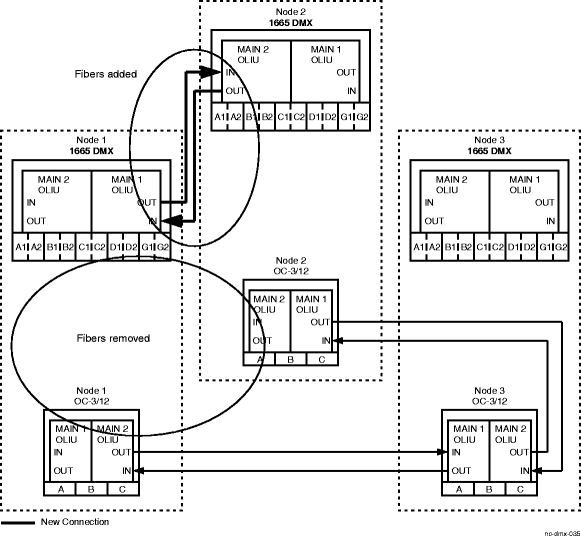
Important! A protection switch may occur when fibers are removed and cause a transmission hit. This procedure begins at one location and progresses around the ring until all optical fiber connections are made. Reference: Procedure 14-4: Perform connection and verification of optical facility |
11 |
At Alcatel-Lucent 1665 DMX Node 1, connect the optical fibers from DDM-2000 Node 1 MAIN1 slot to Alcatel-Lucent 1665 DMX Function Group Slot A1, B1, C1, D1, or Growth slot G1. See Figure 12-4, Second figure in upgrade sequence. Reference: Procedure 14-4: Perform connection and verification of optical facility |
12 |
At Alcatel-Lucent 1665 DMX Node 2, connect the optical fibers from DDM-2000 Node 2 MAIN2 slot to Alcatel-Lucent 1665 DMX Function Group Slot A2, B2, C2, D2, or Growth slot G2. See Figure 12-4, Second figure in upgrade sequence. Figure 12-4: Second figure in upgrade sequence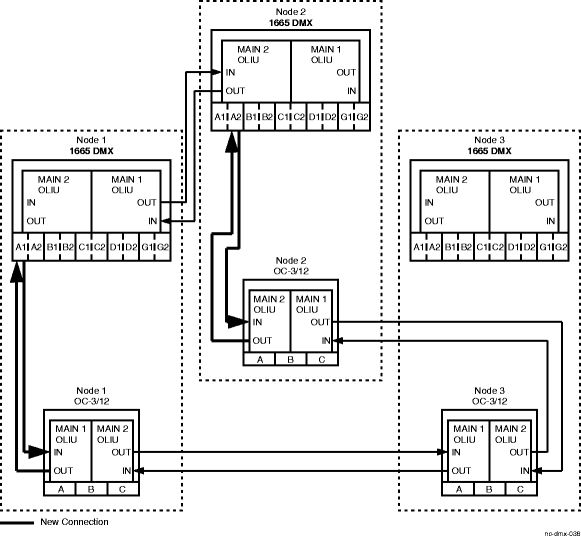
Reference: Procedure 14-4: Perform connection and verification of optical facility |
13 |
Click on the Alarm List button and verify that no alarms are being reported for channels that are connected between MAIN-1 of the DDM-2000 shelf at Node 1 (through the Alcatel-Lucent 1665 DMXs at Nodes 1 and 2) and MAIN-2 of the DDM-2000 at Node 2. If there are any alarms, recheck the cross-connections at the Alcatel-Lucent 1665 DMXs. |
14 |
See Figure 12-5, Third figure in upgrade sequence. Disconnect the fiber pair between DDM-2000 Nodes 2 and 3. If required, use these fibers to connect Alcatel-Lucent 1665 DMX Node 2 and Node 3. Figure 12-5: Third figure in upgrade sequence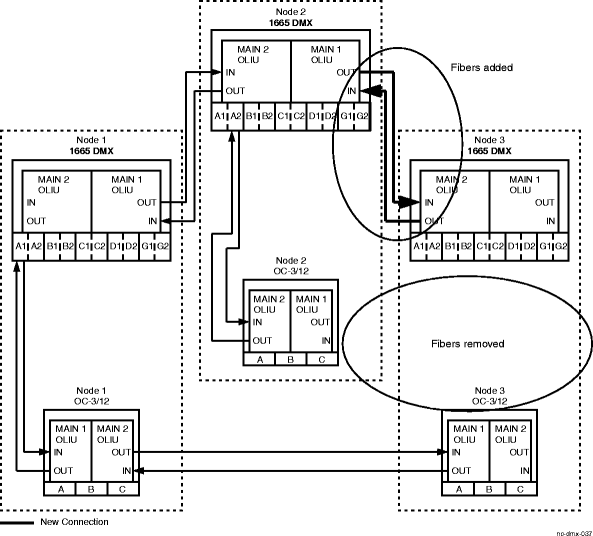
Reference: Procedure 14-4: Perform connection and verification of optical facility |
15 |
See Figure 12-6, Fourth figure in upgrade sequence. At Alcatel-Lucent 1665 DMX Node 2, connect the optical fibers from DDM-2000 Node 2 MAIN1 slot to Alcatel-Lucent 1665 DMX Function Group slot A1, B1, C1, D1, or Growth slot G1. Reference: Procedure 14-4: Perform connection and verification of optical facility |
16 |
At Alcatel-Lucent 1665 DMX Node 3, connect the optical fibers from DDM-2000 Node 3 MAIN2 slot to Alcatel-Lucent 1665 DMX Function Group slot A2, B2, C2, D2, or Growth slot G2. See Figure 12-6, Fourth figure in upgrade sequence. Figure 12-6: Fourth figure in upgrade sequence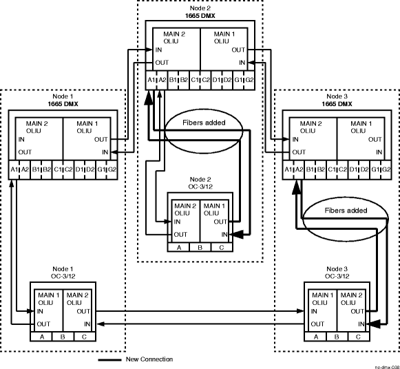
Reference: Procedure 14-4: Perform connection and verification of optical facility |
17 |
Click on the Alarm List button and verify that no alarms are being reported for channels that are connected between MAIN-1 of the DDM-2000 shelf at Node 2 (through the Alcatel-Lucent 1665 DMXs at Nodes 2 and 3) and MAIN-2 of the DDM-2000 at Node 3. If there are any such alarms, recheck the cross-connections at the Alcatel-Lucent 1665 DMXs. |
18 |
See Figure 12-7, Fifth figure in upgrade sequence. Disconnect the fiber pair between DDM-2000 Nodes 2 and 3. If required, use these fibers to connect Alcatel-Lucent 1665 DMX Nodes 1 and 3. Figure 12-7: Fifth figure in upgrade sequence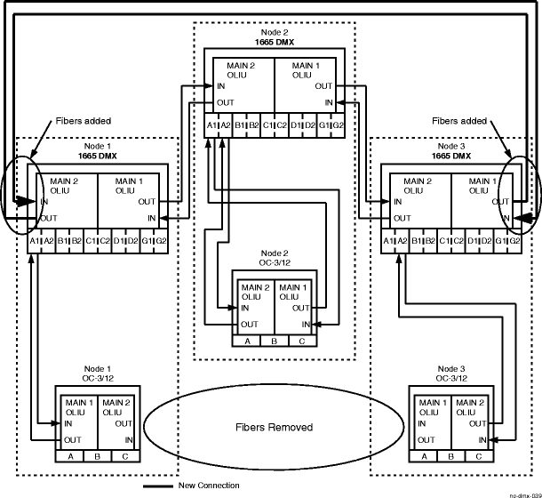
Reference: Procedure 14-4: Perform connection and verification of optical facility |
19 |
See Figure 12-8, Final configuration in upgrade sequence. At Alcatel-Lucent 1665 DMX Node 3, connect the optical fibers from DDM-2000 Node 3 MAIN1 slot to Alcatel-Lucent 1665 DMX Function Group slot A1, B1, C1, D1, or Growth slot G1. Reference: Procedure 14-4: Perform connection and verification of optical facility |
20 |
At Alcatel-Lucent 1665 DMX Node 1, perform the optical fiber connections from DDM MAIN2 slot to Alcatel-Lucent 1665 DMX Function Group Slot A, B, C, D, or G 2. See Figure 12-8, Final configuration in upgrade sequence. Reference: Procedure 14-4: Perform connection and verification of optical facility |
21 |
Click on the Alarm List button and verify that no alarms are being reported for channels that are connected between MAIN-1 of the DDM shelf at Node 3 (through the Alcatel-Lucent 1665 DMXs at Nodes 3, 2, and 1) and MAIN-2 of the DDM at Node 1. If there are any such alarms, recheck the cross-connections at the Alcatel-Lucent 1665 DMXs. |
22 |
Refer to the work instructions and determine the timing/synchronization plan for each node. Select Configuration → Timing/Sync from the System View menu at each node. Click on the tab that is labeled System Timing and select the appropriate options for that particular node. Important! The simplest timing configuration would be to set one Alcatel-Lucent 1665 DMX node to receive external timing from the BITS clock, and all other nodes in the network to receive line timing. Many other timing configurations are possible. |
23 |
At any one of the Alcatel-Lucent 1665 DMX nodes select Administration → OSI Routing Map in order to verify that the UPSR is functional. Figure 12-8: Final configuration in upgrade sequence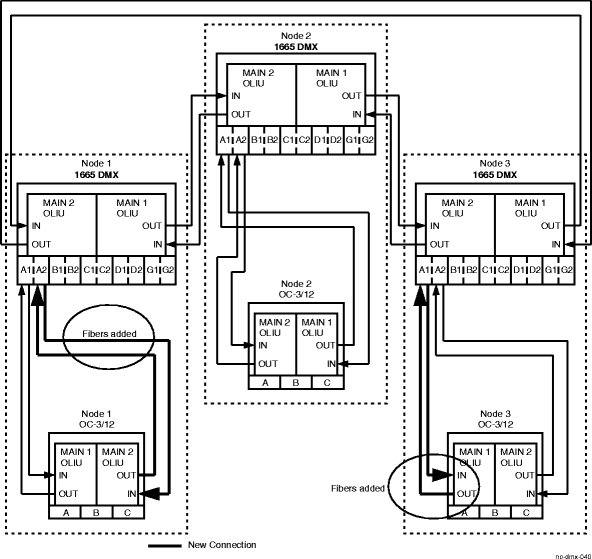
End of steps |