Procedure 14-11: Perform EC-1 transmission test
 Overview
Use this procedure to test an EC-1 port at a stand-alone Alcatel-Lucent 1665 DMX shelf or in a Alcatel-Lucent 1665 DMX network.
If this procedure is being used to perform end-to-end testing in a Alcatel-Lucent 1665 DMX network, it is assumed that the complete Alcatel-Lucent 1665 DMX network configuration (BLSR, UPSR, 1+1, Bidirectional 1+1, or Optimized 1+1) has already been established/tested and that only a particular EC-1 port is being tested at this time.
In end-to-end testing, one shelf is referred to as the near end and the other shelf as the far end. These designations are arbitrary; either shelf can be the near-end or the far-end shelf.
Important!
The Port Maintenance parameter for the affected ports must be provisioned Allow to perform this procedure. If the Port Maintenance parameter for the affected ports is provisioned Inhibit, loopback and test transmission commands for the affected ports are denied.
To view the Port Maintenance parameter, a Privileged, General, Maintenance, or Reports Only user must select Administration → Allow/Inhibit Port Maintenance to access the required port.
To provision the Port Maintenance parameter, a Privileged user must perform Procedure 7-23: Allow/inhibit port/tributary maintenance.
 Privilege level
You must log in as either a Privileged or General user to complete this procedure.
Required equipment
In addition to the equipment listed in Required equipment, an EC-1 SONET Test Set is also required.
 Before you begin
Prior to performing this procedure:
-
Refer to Before you begin in this chapter.
-
Refer to Laser safety and Electrostatic discharge in Chapter 1, Safety.
-
Obtain the work instructions for this procedure and note the assigned AIDs.
-
Select View → Equipment to access the required EC-1 port and verify that the EC-1 port parameters have been provisioned correctly (according to the work instructions) at the terminating Alcatel-Lucent 1665 DMX shelf(s) of the circuit being tested.
If required, select Configuration → Equipment to make EC-1 port provisioning changes.
Refer to Procedure 4-7: Provision DS3/EC1 circuit packs/ports for service for more information.
Steps
Complete the following steps to perform the EC-1 transmission test.
1 |
Important! Proper terminating and pass-through cross-connections must exist at each shelf (including stand-alone shelves) to establish the continuity for the EC-1 circuit being tested. Select Configuration → Cross-Connections to make/verify the proper STS-1 cross-connections for the EC-1 circuit to be tested, as required. Reference: Alcatel-Lucent 1665 Data Multiplexer (DMX) TL1 Message Details, 365-372-306 | ||||||
2 |
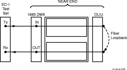
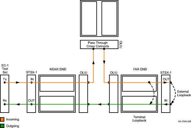
Reference: The following figures show the test arrangements. Figure 14-13: Stand-Alone shelf with OLIU loopback
Figure 14-14: End-to-End EC-1 circuit with far-end loopback | ||||||
3 |
At the near end, connect a SONET test set to the EC-1 port to be tested at the STSX-1 panel or equivalent connection point and apply an EC-1 test signal. | ||||||
4 |
Was the test successful (error free)?
| ||||||
5 |
Is the protection slot associated with the EC-1 circuit under test equipped with a companion DS3/EC1 circuit pack?
| ||||||
6 |
Select Fault → Protection Switch to perform a manual switch from the current active circuit pack to the standby circuit pack. This may cause a hit and register some errors during the switch. | ||||||
7 |
Was the circuit pack protection switch successful (recovered error free)?
| ||||||
8 |
Was the test successful (error free)?
| ||||||
9 |
Are you performing this test for a stand-alone Alcatel-Lucent 1665 DMX shelf or for end-to-end testing within a Alcatel-Lucent 1665 DMX network?
| ||||||
10 |
Remove the fibers used to loop back the circuit under test and disconnect the SONET test set from the STSX-1 panel or equivalent connection point. Important! Unterminated EC-1 circuits require a 75 ohm termination or loopback at the STSX-1 to prevent incoming alarm indications. | ||||||
11 |
Delete the cross-connections entered to perform this procedure. Reference: Procedure 10-4: Discontinue DS3 or EC-1 service | ||||||
12 |
In the System View screen, select Configuration → Update System → Update All to retire existing alarms caused by this procedure. | ||||||
13 |
If required, repeat Step 1 through Step 12 for each EC-1 circuit to be tested. | ||||||
14 |
STOP! End of Procedure. | ||||||
15 |
At the near end, disconnect the SONET test set from the STSX-1 panel or equivalent connection point. | ||||||
16 |
At the near end and far end, delete any cross connections entered to perform this procedure. Reference: Procedure 10-4: Discontinue DS3 or EC-1 service | ||||||
17 |
At the far end, select Fault → Analysis → Loopback to release the terminal loopback, or remove the patch cords at the STSX-1 panel or equivalent connection point the circuit under test. | ||||||
18 |
At the near end and far end, select Configuration → Update System → Update All to retire existing alarms caused by this procedure. | ||||||
19 |
If required, return to Step 1 and repeat this procedure for each EC-1 circuit to be tested. | ||||||
20 |
STOP! End of Procedure. | ||||||
21 |
Has the DS3/EC1 circuit pack that failed this test been replaced?
| ||||||
22 |
Replace the DS3/EC1 circuit pack and repeat this procedure. Reference: Alcatel-Lucent 1665 Data Multiplexer (DMX) Alarm Messages and Trouble Clearing Guide, 365-372-302 | ||||||
23 |
Trouble may be in the STSX-1 cross-connect wiring, EC-1 interface wiring, STS-1 cross-connections in the network, or the shelf backplane. If you continue to experience problems, contact your next level of support. Reference: Alcatel-Lucent 1665 Data Multiplexer (DMX) Alarm Messages and Trouble Clearing Guide, 365-372-302 End of steps |