Procedure 10-7: Make 1+1 (linear extension) cross-connections
 Overview
Use this procedure to provision cross-connections at a Alcatel-Lucent 1665 Data Multiplexer Extend shelf serving as a terminating node for a 1+1 optical extension.. This procedure uses the CIT Cross-Connection Wizard commands to illustrate the provisioning. The same provisioning may be made using the TL1 ent-crs-( ) command. See Alcatel-Lucent 1665 Data Multiplexer Extend (DMXtend) TL1 Message Details, 365-372-328 for rates, types, restrictions, and allowable cross-connections. Note that E1 services require an STS-3c cross-connection.
 Before you begin
Prior to performing this procedure:
-
Refer to Before you begin and Required equipment in this chapter.
-
Refer to Laser safety and Electrostatic discharge in Chapter 1, Safety.
-
Verify that the 1+1 optical extension has been established using the procedures in Procedure 9-4: Establish low-speed 1+1 linear optical extension.
-
Determine the cross-connection types, rates, and terminating nodes for the optical extension.
Steps
Complete the following steps to make the necessary cross-connections.
1 |
Use the WaveStar® CIT to log in to one of the Alcatel-Lucent 1665 DMXtend host nodes providing the 1+1 extension. Reference: Procedure 14-2: Connect Personal Computer (PC) and establish WaveStar® CIT session |
2 |
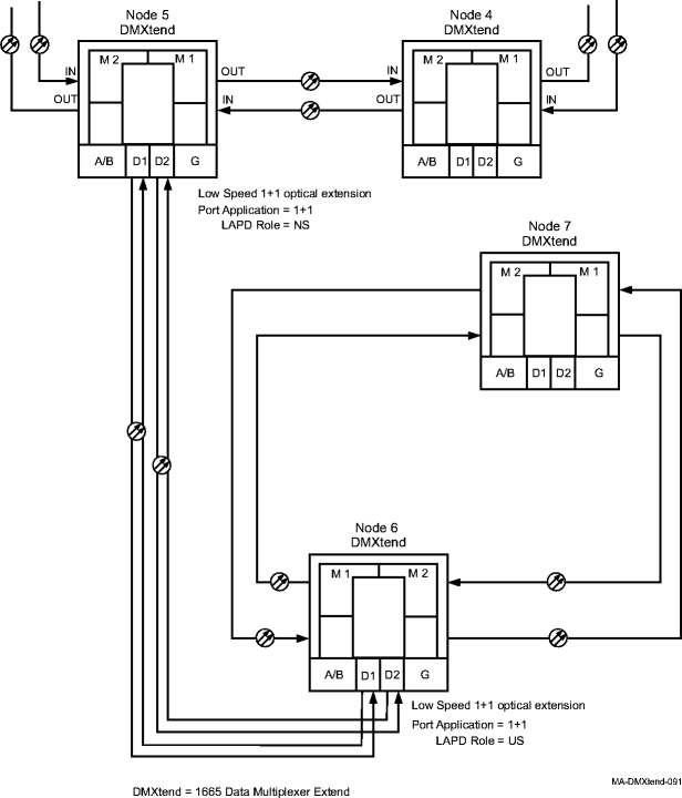
Refer to Figure 10-4, Two Alcatel-Lucent 1665 DMXtend UPSRs connected in a 1+1 (linear extension) for an example of two Alcatel-Lucent 1665 DMXtend UPSRs connected in a 1+1 (linear extension) configuration. Figure 10-4: Two Alcatel-Lucent 1665 DMXtend UPSRs connected in a 1+1 (linear extension) |
3 |
On the System View menu, select Administration → OSI Routing Map to retrieve a node-to-node listing of every node on the Alcatel-Lucent 1665 DMXtend rings. Important! If a drawing of the network is not provided with the work instructions, it is recommended that you draw a simple diagram of the ring (indicating node-to-node connections) and list each node's TID. This command may take several minutes to complete depending on the size of the network. Result: The OSI Routing Map window opens. |
4 |
Verify that the network configuration is the same as specified in the work instructions. Important! All differences between the work instructions and the actual ring configuration must be resolved before continuing. |
5 |
From the work instructions, determine the terminating (add/drop) nodes at each end of the 1+1 optical extension. |
6 |
One at a time, use the WaveStar® CIT to log in to each terminating node. From the System View menu at each node, select View → Equipment. Result: The View Equipment window opens. |
7 |
Find the circuit pack, port, and/or tributaries being used for this service. Select the entity to view, then click the Select button at the bottom of the window. View the provisioning details for the selected entity and verify the entities are properly provisioned. |
8 |
If the entities are not provisioned properly, use the procedures in this chapter to condition the circuit packs/ports for service. |
9 |
From your work instructions, determine the type of cross-connections to be made at each node for the service being established. |
10 |
At each of the terminating nodes for the circuit being established, select View → Cross-Connections from the System View menu to verify that the cross-connections specified on the work instructions may be made. If cross-connections are already assigned or improperly assigned, refer trouble to the provisioning organization. Improperly assigned cross-connections may have to be deleted, or a different timeslot must be selected for the service being selected. |
11 |
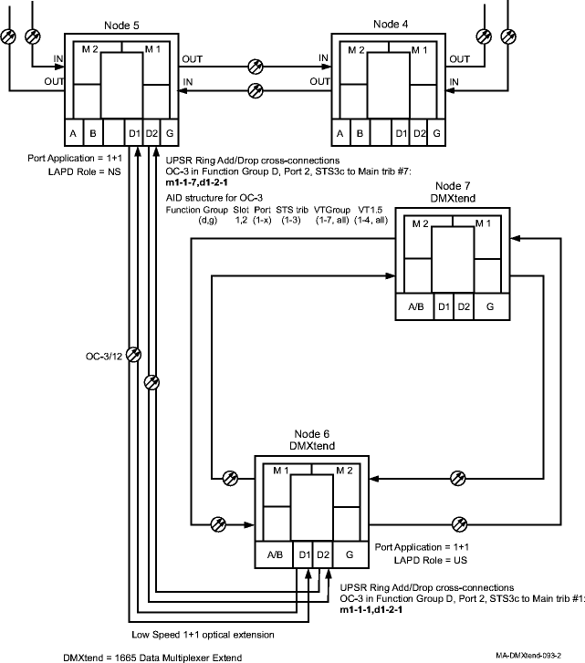
Select Configuration → Cross-Connections from the System View menu to start the Cross-Connection Wizard. Use the Cross-Connection Wizard to provision the add/drop cross-connections at each terminating node serving the optical extension. Figure 10-5, 1+1 STS3c cross-connection examples illustrates an example network with 1+1 STS3c cross-connections at Alcatel-Lucent 1665 DMXtend Nodes 5 and 6. Figure 10-5: 1+1 STS3c cross-connection examples |
12 |
From the System View menu, select View → Cross-Connections at each node to verify that the proper connection has been made. |
13 |
If other cross-connections are to be made, for example, from a terminating node in one ring to a terminating node in the other ring, refer to the appropriate procedures in this chapter to establish the particular service. |
14 |
After all cross-connections have been made, verify that the channels have gone in service at each terminating node. From the System View menu at each terminating node, select View → Equipment. Result: The View Equipment window opens. The provisioned cross-connections create connections to both sides of the ring. The channel state will transition once a good signal is received on either side of the ring. Note there will be channel states on the tributaries of the 1+1 interface as well. |
15 |
Expand the details for the circuit pack being used. Select the required port, then click Select at the bottom of the window. Verify the port AID is correct at the top of the parameter display. |
16 |
Under Port Data/Fault in the parameter display, verify the Port Monitoring Mode is IS (in service). If the Port Monitoring Mode is IS, then Stop, you have completed this procedure. Otherwise, perform one of the following:
Reference: Alcatel-Lucent 1665 Data Multiplexer Extend (DMXtend) Alarm Messages and Trouble Clearing Guide, 365-372-326 End of steps |