Procedure 9-4: Establish low-speed 1+1 linear optical extension
 Overview
Use this procedure to establish a low-speed 1+1 linear OC-3/12/48 optical extension.
Important!
This procedure assumes that the low-speed 1+1 optical linear extension is established by interconnecting a OC-3/12/48 Function/Growth slot pair at the host Alcatel-Lucent 1665 DMXtend to one of the following:
-
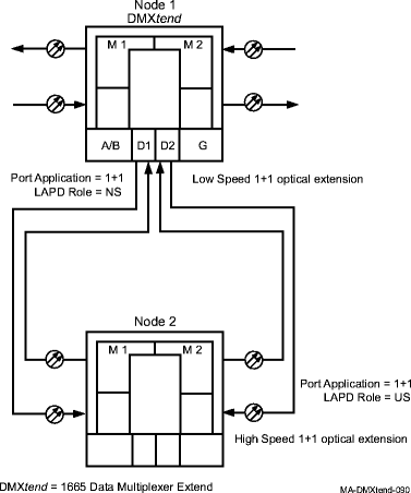
Alcatel-Lucent 1665 DMXtend OC-3/12/48 Main slot pair: Figure 9-3, 1+1 extension example 1 shows an Alcatel-Lucent 1665 DMXtend at Node 1 with low-speed OC-3/12/48 OLIUs in Function slot pair D1/D2 connected to Node 2 Main slot pair. If connecting to the Main slot pair of another Alcatel-Lucent 1665 DMXtend, refer to Procedure 9-1: Establish high-speed end-to-end Alcatel-Lucent 1665 DMXtend network, as required, when performing this procedure.
-
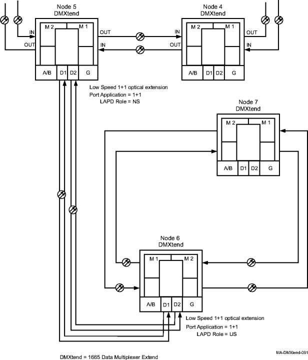
Alcatel-Lucent 1665 DMXtend OC-3/12/48 Function/Growth slot pair: Figure 9-4, 1+1 extension example 2 shows an Alcatel-Lucent 1665 DMXtend at Node 6 with low-speed OC-3/12/48 OLIUs in Function slot pair D1/D2 connected to Node 5 low-speed D1/D2 Function slot pair.
The Function/Growth slot pair at the host Alcatel-Lucent 1665 DMXtend may also be connected to the following:
-
Alcatel-Lucent 1665 DMX OC-3/12/48 Main slot pair or an OC-3/12/48 Function/Growth slot pair: If connecting to an Alcatel-Lucent 1665 DMX, refer to the Alcatel-Lucent 1665 Data Multiplexer (DMX) User Operations Guide, 365-372-301, as required, when performing this procedure.
-
Alcatel-Lucent 1665 DMXplore OC-3/12 Main slot pair: If connecting to an Alcatel-Lucent 1665 DMXplore, refer to the Alcatel-Lucent 1665 Data Multiplexer Explore (DMXplore) User Operations Guide, 365-372-332 as required, when performing this procedure.
Ignore all alarms until the procedure is complete.
 Before you begin
Prior to performing this procedure:
-
Refer to Before you begin and Required equipment in this chapter.
-
Refer to Laser safety and Electrostatic discharge in Chapter 1, Safety.
-
Verify that you have the necessary work instructions detailing the slots, circuit packs, ports, and network element parameters to be used for this procedure.
-
Verify that the network containing the host Alcatel-Lucent 1665 DMXtend node is established and operating properly.
-
Verify that the far-end node being connected to the host Alcatel-Lucent 1665 DMXtend node has been equipped and is operating properly.
Steps
Complete the following steps to establish a low-speed 1+1 optical extension.
1 |
Determine the network configuration using the work instructions and office records. Refer to the examples in Figure 9-3, 1+1 extension example 1 and Figure 9-4, 1+1 extension example 2. | ||||||||
2 |
Important! Two or more shelves in the same network cannot have the same TID. Using the work instructions and office records, verify that no duplicate TID settings exist between the host Alcatel-Lucent 1665 DMXtend and the far-end node. If duplicate TID settings exist, determine new settings and at each site with duplicate TID settings, select Administration → Set TID from the System View menu, and enter new TID settings. Reference: Procedure 7-11: Set/change system TID | ||||||||
3 |
If required, modify the network service access point (NSAP) address and/or enable Level 2 routing capabilities at the host Alcatel-Lucent 1665 DMXtend and the far-end node. Reference: Procedure 7-13: Provision network layer 3 parameters | ||||||||
4 |
At the host Alcatel-Lucent 1665 DMXtend node, verify/install OLIU circuit packs and/or pluggable transmission modules in the Function Group slot pair (D1 and D2, or G1 and G2) being used for access according to the work instructions. Important! If the work instructions or office records do not specify OLIU types, refer to Alcatel-Lucent 1665 Data Multiplexer Extend (DMXtend) Applications and Planning Guide, 365-372-324, for a description of OLIU circuit packs/pluggable transmission modules and applications. Optical line power measurements and/or office records must be used to verify that the span length can be supported. The connections to the Alcatel-Lucent 1665 DMXtend shelf must be in two slots in the same Function/Growth group (for example: D1 and D2). Reference: | ||||||||
5 |
Important! If OSI over DCC is enabled for ports, an inconsistent DCC values alarm is reported when the ports are looped back. If required at the host Alcatel-Lucent 1665 DMXtend node, clear the inconsistent DCC values alarm by disabling OSI over DCC for the required ports. From the System View menu, select Configuration → DCC Terminations and disable OSI Over DCC for the required DCC ports. Reference: Procedure 6-4: Provision DCC terminations | ||||||||
6 |
Important! The port Application parameter must be provisioned 1+1 at both ends of the system or Bidirectional 1+1 at both ends of the system. Bidirectional 1+1 is required when interworking with other vendor's equipment that does not bridge DCC traffic on the active and standby lines. (Alcatel-Lucent 1665 DMXtend supports bridging DCC traffic on the active and standby lines.) Alcatel-Lucent 1665 DMXplore does not support Bidirectional 1+1. From the System View menu at the host Alcatel-Lucent 1665 DMXtend node, select Configuration → Equipment. One at a time, select the required ports, and provision the required port parameters according to the work instructions. Reference: Procedure 4-4: Provision OLIU circuit packs/ports for service | ||||||||
7 |
From the System View menu at the host Alcatel-Lucent 1665 DMXtend node, select Configuration → Equipment. Select the Alcatel-Lucent 1665 DMXtend (AID=system), then click Select at the bottom of the window. If required, provision the 1+1 Protection Priority parameter (1+1 applications only). Click Apply if changes were made, then click Yes to the warning message to make your changes. Click Close to exit. | ||||||||
8 |
At the host Alcatel-Lucent 1665 DMXtend node, verify that the low-speed OC-n ports were provisioned correctly using the View → Equipment command. | ||||||||
9 |
Important! If OSI over DCC is enabled, the LAPD Role parameter must be provisioned differently at each end of an optical span. For example, if the LAPD Role parameter is provisioned to user-side at one end of an optical span, then the LAPD Role parameter must be provisioned network-side at the other end of the optical span. From the System View menu, select Configuration → DCC Terminations and provision the DCC terminations for the required DCC ports according to the work instructions. Result: If OSI over DCC is enabled, an inconsistent DCC values alarm will occur if the OC-n ports are looped back. Reference: Procedure 6-4: Provision DCC terminations | ||||||||
10 |
From the System View menu at the host Alcatel-Lucent 1665 DMXtend node, select View → DCC Terminations and verify that the DCC terminations were provisioned correctly. | ||||||||
11 |
At the far-end node that is connecting to the host Alcatel-Lucent 1665 DMXtend node, provision the required Main/Function/Growth ports, DCC terminations, synchronization, and remote NE status functions according to the work instructions.
| ||||||||
12 |
Important! The circuit pack in slot D1 or G1 of the host Alcatel-Lucent 1665 DMXtend node must be connected to the far-end circuit pack in Main/Function/Growth slot 1, and the circuit pack in slot D2 or G2 of the host Alcatel-Lucent 1665 DMXtend node must be connected to the far-end circuit pack in Main/Function/Growth slot 2. Connect the optical fibers and verify the integrity of the optical span being installed. Reference: Procedure 14-4: Perform connection and verification of optical facility | ||||||||
13 |
Perform end-to-end optical line test. Reference:
| ||||||||
14 |
At each node in the 1+1 linear network, click the Alarm List button and verify that no alarms are present. If required, clear any alarms that are present. Reference: Alcatel-Lucent 1665 Data Multiplexer Extend (DMXtend) Alarm Messages and Trouble Clearing Guide, 365-372-326 | ||||||||
15 |
Important! Establishing service requires that the proper slots in each terminating node be properly equipped with the correct circuit pack(s) for the type of service being established. It also requires numerous cross-connections in each of the nodes representing the path of the required service. Additionally, transmission tests should be performed to verify the continuity and quality of the established circuit. The optical 1+1 linear extension is now ready for initial service to be established. Reference: End of steps |
Figure 9-3: 1+1 extension example 1

Figure 9-4: 1+1 extension example 2
