Procedure 14-22: Establish external test access session in the MON(E or EF) mode
 Overview
Use this procedure to establish a new external test access session in the following test access modes:
To establish an internal test access session in the MONE mode, refer to Procedure 14-30: Establish internal test access session in the MONE mode.
A new external test access session can be created only in the MONE or MONEF test access mode initially. To change the test access mode of an existing test access session, refer to Procedure 14-24: Change test access mode of external test access session.
Important!
The Tributary Maintenance parameter for the affected connected tributaries must be provisioned Allow to perform this procedure. If the Tributary Maintenance parameter for the affected connected tributaries is provisioned to Inhibit, test access commands for the affected ports are denied. Unconnected tributaries are always available for test access.
To view the Tributary Maintenance parameter, a Privileged, General, Maintenance, or Reports Only user must select Administration → Allow/Inhibit Tributary Maintenance to access the required tributary.
To provision the Tributary Maintenance parameter, a Privileged user must perform Procedure 7-23: Allow/inhibit port/tributary maintenance.
 Privilege level
You must log in as either a Privileged, General, or Maintenance user to complete this procedure.
MONE mode
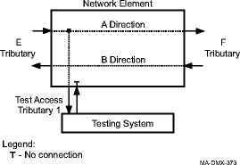
The MONE mode is used to monitor the E Tributary input signal of a one-way cross-connection, a two-way cross-connection, or an idle E Tributary input signal (no cross-connection).
The following figure shows an example of the MONE mode used to monitor the E Tributary input signal of a two-way cross-connection.

If the F Tributary is entered, the F Tributary must be the destination of a one-way cross-connection that has the E Tributary as the source, or the F Tributary must be part of a two-way cross-connection that does not have any other test access sessions on it. If the E Tributary is part of a two-way multicast cross-connection, entering the F Tributary is optional. The system automatically retrieves the other end. The E Tributary or F Tributary cannot be on an Ethernet circuit pack.
MONEF mode
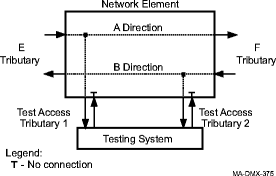
The MONEF mode is used to monitor the E Tributary input signal and the F Tributary input signal of a two-way cross-connection.
The following figure shows an example of the MONEF mode used to monitor two tributaries.

The E Tributary, F Tributary, and two test access tributaries are required. If the E Tributary is part of a two-way cross-connection, entering the F Tributary is optional. The MONEF mode is not supported for tributaries that have one-way cross-connections or idle tributaries (no cross-connections). The E Tributary or F Tributary cannot be on an Ethernet circuit pack.
VT1.5 test access matrix
The "dual tatrib" modes (MONEF and SPLTEF) of VT test access are not possible when the system is equipped with small/medium VT fabric Main OLIUs. This applies to all systems equipped with OC3 or OC12 Main OLIUs.
The table below provides all the VT1.5 test access specifications supported by Alcatel-Lucent 1665 DMXtend. The numbers in the table below indicate the software release number in which that configuration is first supported.
Table 14-1: VT1.5 test access
|
TATRIBs | ||||||||||
|---|---|---|---|---|---|---|---|---|---|---|
|
Slot |
Signal |
A slot |
A/B D/G slots (Elect) |
|||||||
|
DS3 |
EC1 |
TMUX (D–G) |
DS1/E1 |
OC-3 |
OC-12 |
OC48 | ||||
|
LNW39 LNW111 LNW112 LNW391 |
LNW16 LNW19B LNW20 |
LNW18 LNW20 |
LNW7 LNW8 LNW801 |
LNW37 LNW45 LNW55 |
LNW49 LNW55 |
LNW31 LNW55 LNW62 | ||||
|
ETRIB and FTRIB |
Main Add/Drop VT1.5 XC to: 4 |
A–G |
EC1 3 |
R2.0 |
R2.0 |
R2.0 |
R2.0 |
R2.0 |
R3.1 |
R2.0 |
|
TMUX |
R2.0 |
R2.0 |
R2.0 |
R2.0 |
R2.0 |
R3.1 |
R2.0 | |||
|
D–G |
OC-3/12 /48 |
R2.0 |
R2.0 |
R2.0 |
R2.0 |
R2.0 |
R3.1 |
R2.0 | ||
|
DS1/E1 (FN B–G) VT1.5 hairpin to: 4 |
A–G |
EC1 3 |
R2.0 |
R2.0 |
R2.0 |
R2.0 |
R2.0 |
R3.1 |
R2.0 | |
|
TMUX |
R2.0 |
R2.0 |
R2.0 |
R2.0 |
R2.0 |
R3.1 |
R2.0 | |||
|
D–G |
OC-3/12 /48 |
R2.0 |
R2.0 |
R2.0 |
R2.0 |
R2.0 |
R3.1 |
R2.0 | ||
|
OC3/12 /48 (FN D–G) VT1.5 hairpin to: 4 |
A–D |
EC1 3 |
R2.0 |
R2.0 |
R2.0 |
R2.0 |
R2.0 |
R3.1 |
R2.0 | |
|
TMUX |
R2.0 |
R2.0 |
R2.0 |
R2.0 |
R2.0 |
R3.1 |
R2.0 | |||
|
D–G |
OC-3/12 /48 |
R2.0 |
R2.0 |
R2.0 |
R2.0 |
R2.0 |
R3.1 |
R2.0 | ||
|
TMUX (LNW20 portless only) |
R5.0 |
R5.0 |
R5.0 |
R5.0 |
R5.0 |
R5.0 |
R5.0 | |||
Notes:
TATRIB1 and TATRIB2 are always connected to the same optical interface.
Intended for unprotected interfaces to locally-connected testheads only; Network-connected testheads - Future\
Test Access of UPSR Dual Ring Interworking cross-connections not supported
STS-1 test access matrix
The table below provides all the STS-1 test access specifications supported by Alcatel-Lucent 1665 DMXtend. The numbers in the table below represent the software release number in which that configuration is first supported. Test access on STS-3(c) signals is only supported in SPLTA, SPLTE, and MONE modes using the internal test head located in the VLF Main packs for PRBS generation/detection
Table 14-2: STS-1 test access
|
TATRIBs | |||||||||
|---|---|---|---|---|---|---|---|---|---|
|
Slot |
Signal |
B slot |
D & G slots (Elect) |
||||||
|
DS3 |
DS3/EC1 |
TMUX |
OC3 |
OC12 |
OC48 | ||||
|
LNW39 LNW111 LNW112 LNW391 |
LNW16 LNW19B LNW20 |
LNW18 LNW20 |
LNW37 LNW45 LNW55 |
LNW49 LNW55 |
LNW31 LNW55 LNW62 | ||||
|
ETRIB and FTRIB |
B–G |
EC1 |
R2.0 |
R2.0 |
Deny |
R2.0 |
R3.1 |
R3.1 | |
|
D–G |
OC-3/12/ 48 |
R2.0 |
R2.0 |
Deny |
R2.0 |
R3.1 |
R3.1 | ||
|
Thru STS XC |
R3.1 |
R3.1 |
Deny |
R3.1 |
R3.1 |
R3.1 | |||
|
D–G |
DS3/EC1 |
R2.0 |
R2.0 |
Deny |
2.0 |
3.1 |
3.1 | ||
|
D–G |
OC-3/12/ 48 |
R2.0 |
R2.0 |
Deny |
2.0 |
3.1 |
3.1 | ||
|
B–G |
DS3/EC1 |
R2.0 |
R2.0 |
Deny |
2.0 |
3.1 |
3.1 | ||
|
D–G |
OC-3/12/ 48 |
R2.0 |
R2.0 |
Deny |
2.0 |
3.1 |
3.1 | ||
|
D–G |
TMUX |
R5.0 |
R5.0 |
R5.0 |
R5.0 |
R5.0 |
R5.0 | ||
Notes:
TATRIB1 and TATRIB2 are always connected to the same optical interface.
Intended for network-connected testheads where the tributary under test is in one NE and the test head is connected to a different NE.
Test Access of locked cross-connections restricted to electrical TATRIBs
Test Access of UPSR Dual Ring Interworking cross-connections is not supported.
Restrictions
The following restrictions apply when establishing an external test access session in the MON(E or EF) mode.
-
A new external test access session can be created only in the MONE or MONEF test access mode initially.
-
A new test access session is denied if a node or ring network upgrade is active (node is in provisioned Ring Upgrade mode).
-
A new test access session is denied if a transmission test, loopback, or test access session is already active on an affected port.
-
If the Main slots are equipped with LNW40/LNW302/LNW601 OC-3 or LNW38/LNW51/LNW382 OC-12 OLIU circuit packs, the VT1.5 test access cross-connection capacity is limited because of the small VT switch fabric. Therefore, it is recommended that you use only the MONE or SPLTE mode and avoid using ports on the LNW6, LNW7, LNW39, LNW111, and LNW112 circuit packs for the E Tributary, F Tributary, and Test Access Tributaries.
-
If the E Tributary or F tributary is part of a locked DSn cross-connection, the Test Access Tributary connected to the optical side of the locked DSn cross-connection must be an idle tributary of an electrical interface with a matching rate.
-
Test Access of UPSR Dual Ring Interworking cross-connections is not supported.
-
Test Access of VT1.5 through cross-connections (UPSR) is not supported.
-
Up to 12 simultaneous test access sessions are supported, regardless of the test access rate and type (external or internal).
|
NOTICE Service-disruption hazard |
Service interruptions may occur on unintended tributaries if unsupported test access configurations are attempted.
Recheck the address (AID) of the tributary(ies) being tested and the test access tributary(ies). Do not attempt to establish unsupported test access sessions.
 Before you begin
Prior to performing this procedure:
-
Refer to Before you begin and Required equipment in this chapter.
-
Refer to Laser safety and Electrostatic discharge in Chapter 1, Safety.
-
Verify that the work instructions identify the test access mode, test access rate, and the assigned addresses (AIDs) of the tributary(ies) to be tested and the test access tributary(ies).
-
If the work instructions specify optical test access tributaries are to be used, verify that 1+1 optical interfaces to locally-connected testheads exist. If required, refer to Procedure 9-9: Establish low-speed 1+1 unprotected optical linear extension to establish a 1+1 interface to the local testhead.
Steps
Complete the following steps to establish a new external test access session in the MON(E or EF) mode.
1 |
Verify that the Test Access Tributary Tributary Monitoring Mode parameter is provisioned to NMON. Select View → Equipment. Expand the required circuit pack and port details, highlight the required tributary, and click Select to obtain a list of tributary parameters. |
2 |
If required, provision the Test Access Tributary Tributary Monitoring Mode parameter to NMON to avoid possible alarms. Select Configuration → Equipment. Expand the required circuit pack and port details, highlight the required tributary, and click Select. Provision the Tributary Monitoring Mode parameter to NMON. Click Apply and Close. |
3 |
If creating a new test access session between a low-speed electrical port (for example, DS1 or DS3) and a Test Access Tributary, provision the low-speed electrical port Port Monitoring Mode parameter to NMON to avoid possible alarms. Select Configuration → Equipment. Expand the required low-speed electrical circuit pack details, highlight the required low-speed electrical port, and click Select. Provision the Port Monitoring Mode parameter to NMON. Click Apply and Close. |
4 |
From the System View menu select Fault → Analysis → Test Access. Result: The Test Access Wizard appears. |
5 |
Click Create a new test access session, External Test Session, and Next. |
6 |
Follow the directions in the remaining Test Access Wizard screens to create a new external test access session in the MONE or MONEF test access mode at the STS-1 or VT1.5 rate according to the work instructions. |
7 |
Important! A test access session remains in effect until deleted. Verify the test access session parameters, then click Finish at the end of the Test Access Wizard screens. Result: A dialog box appears asking you to confirm executing this command. Click Yes and the Test Access Wizard appears. |
8 |
Click View existing test access sessions and Next. Result: A list of existing test access sessions appears. |
9 |
Verify that the required test access session was created and click Close. End of steps |