Procedure 9-12: Establish DWDM OTU2 line
 Overview
Use this procedure to establish a DWDM OTU2 line.
Important!
This procedure assumes that the DWDM OTU2 line is established by interconnecting two Alcatel-Lucent 1665 DMXtend nodes using LNW705 XM10G/8 10G Muxponder circuit packs. However, the XM10G/8 circuit pack at an Alcatel-Lucent 1665 DMXtend node may also be connected to an XM10G/8 circuit pack at an Alcatel-Lucent 1665 DMX node.
This procedure assumes that the near-end node is an Alcatel-Lucent 1665 DMXtend and the far-end node is either an Alcatel-Lucent 1665 DMXtend or Alcatel-Lucent 1665 DMX.
This procedure assumes that all Alcatel-Lucent 1665 DMXtend shelves have been equipped with the required XM10G/8 circuit packs/pluggable transmission modules and software has been installed. If not, refer to Chapter 5, Node turnup procedures.
Ignore all alarms until the procedure is complete.
 Before you begin
Prior to performing this procedure:
-
Refer to Before you begin in this chapter.
-
Refer to Laser safety and Electrostatic discharge information in Chapter 1, Safety.
-
Verify that the work instructions specify the slots, circuit packs, pluggable transmission modules, ports, and network element parameters to be used for this procedure.
Steps
Complete the following steps to a DWDM OTU2 line.
1 |
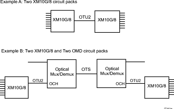
Important! The XM10G/8 circuit pack at the near-end node may be connected to an XM10G/8 circuit pack at the far-end node (initial application), or the XM10G/8 circuit packs may be connected using OMD circuit packs at the near-end and far-end nodes (later applications). Determine the network configuration to be established using the work instructions and office records. Examples:  | ||||||
2 |
Important! The network element TID (target identifier) must be unique in the network. At the near-end node, select Administration → View NE Administration to access the NE administrative parameters. Verify that the NE Parameters and NSAP are provisioned correctly using the work instruction and/or office records and click Close. If provisioning changes are required, refer to the appropriate procedure(s) in Chapter 7, System administration procedures. | ||||||
3 |
At the near-end node, verify/install the required XM10G/8 circuit pack and pluggable transmission module in the required Function/Growth slots. Reference: | ||||||
4 |
At the near-end node, select Configuration → Equipment to access the required XM10G/8 circuit pack and provision the circuit pack/pluggable transmission module/OTU2 port parameters according to the work instructions. Reference: Procedure 4-28: Provision 10G Muxponder circuit pack/optical channel transport unit (OTU2) port | ||||||
5 |
At the far-end node, provision the required node, circuit pack, pluggable transmission module, and OTU2 port functions according to the work instructions.
| ||||||
6 |
| ||||||
7 |
Important! OCH cross-connections to/from an OTU2 port are used to inform the network element about manual fiber connections. This allows the network element to enable alarm reporting and assign the 10G Muxponder internal STS cross-connection fabric to the provisioned client ports. At the near-end and far-end nodes, select Configuration → OCH Cross-Connections to access the OCH Cross-Connection Wizard and provision the required two 1-way OCH cross-connections between the OTU2 port and remote AID (REMAID). | ||||||
8 |
Connect the optical fibers and verify the integrity of the OTU2 line being established. Reference: Procedure 14-4: Perform connection and verification of optical facility | ||||||
9 |
Perform end-to-end OTU2 line test. Reference: Procedure 14-36: Perform end-to-end optical line test on DWDM line | ||||||
10 |
At the near-end and far-end nodes, click the Alarm List button and verify that no alarms are present. If required, clear any alarms that are present. Reference: Alcatel-Lucent 1665 Data Multiplexer Extend (DMXtend) Alarm Messages and Trouble Clearing Guide, 365-372-326 | ||||||
11 |
The OTU2 line is now ready for SONET/GbE/Data client signals to be added. Reference: Procedure 10-16: Add SONET/GbE/Data client signals End of steps |