LAG
A Link Aggregation Group (LAG), based on the IEEE 802.1ax standard (formerly 802.3ad), increases the bandwidth available between two network devices by grouping multiple ports to form one logical interface.
Traffic forwarded to a LAG by the router is load balanced between all active ports in the LAG. The hashing algorithm deployed by Nokia routers ensures that packet sequencing is maintained for individual sessions. Load balancing for packets is performed by the hardware, which provides line rate forwarding for all port types.
LAGs can be either statically configured or formed dynamically with Link Aggregation Control Protocol (LACP). A LAG can consist of same-speed ports or mixed-speed ports.
All ports within a LAG must be of the same Ethernet type (access, network, or hybrid) and have the same encapsulation type (dot1q, QinQ, or null).
The following is an example of static LAG configuration using dot1q access ports.
MD-CLI
[ex:/configure lag "lag-1"]
A:admin@node-2# info
    admin-state enable
    encap-type dot1q
    mode access
    port 1/1/1 {
    }
    port 1/1/2 {
    }
classic CLI
A:node-2>config>lag# info
----------------------------------------------
        mode access
        encap-type dot1q
        port 1/1/1
        port 1/1/2
        no shutdown
----------------------------------------------
LACP
The LACP control protocol, defined by the IEEE 802.3ad standard, specifies the method by which two devices establish and maintain LAGs. When LACP is enabled, SR OS automatically associates LACP-compatible ports into a LAG.
The following is an example of LACP LAG configuration using network ports and a default null encapsulation type.
MD-CLI
[ex:/configure lag "lag-2"]
A:admin@node-2# info
    admin-state enable
    mode network
    lacp {
        mode active
        administrative-key 32768
    }
    port 1/1/3 {
    }
    port 1/1/4 {
    }
classic CLI
A:node-2>config>lag# info
----------------------------------------------
        mode network
        port 1/1/3
        port 1/1/4
        lacp active administrative-key 32768
        no shutdown
----------------------------------------------
LACP multiplexing
The router supports two modes of multiplexing RX/TX control for LACP: coupled and independent.
In coupled mode (default), both RX and TX are enabled or disabled at the same time whenever a port is added or removed from a LAG group.
In independent mode, RX is first enabled when a link state is UP. LACP sends an indication to the far-end that it is ready to receive traffic. Upon the reception of this indication, the far-end system can enable TX. Therefore, in independent RX/TX control, LACP adds a link into a LAG only when it detects that the other end is ready to receive traffic. This minimizes traffic loss that may occur in coupled mode if a port is added into a LAG before notifying the far-end system or before the far-end system is ready to receive traffic. Similarly, on link removals from LAG, LACP turns off the distributing and collecting bit and informs the far-end about the state change. This allows the far-end side to stop sending traffic as soon as possible.
Independent control provides for lossless operation for unicast traffic in most scenarios when adding new members to a LAG or when removing members from a LAG. It also reduces loss for multicast and broadcast traffic.
Note that independent and coupled mode are interoperable (connected systems can have either mode set).
Independent and coupled modes are supported when using PXC ports, however, independent mode is recommended as it provides significant performance improvements.
LACP tunneling
LACP tunneling is supported on Epipe and VPLS services. In a VPLS, the Layer 2 control frames are sent out of all the SAPs configured in the VPLS. This feature should only be used when a VPLS emulates an end-to-end Epipe service (an Epipe configured using a three-point VPLS, with one access SAP and two access-uplink SAP/SDPs for redundant connectivity). The use of LACP tunneling is not recommended if the VPLS is used for multipoint connectivity. When a Layer 2 control frame is forwarded out of a dot1q SAP or a QinQ SAP, the SAP tags of the egress SAP are added to the packet.
The following SAPs can be configured for tunneling the untagged LACP frames (the corresponding protocol tunneling needs to be enabled on the port).
If the port encapsulation is null, a null SAP can be configured on a port to tunnel these packets.
If the port encapsulation is dot1q, either a dot1q explicit null SAP (for example, 1/1/10:0) or a dot1q default SAP (for example, 1/1/11:*) can be used to tunnel these packets.
If the port encapsulation is QinQ, a 0.* SAP (for example, 1/1/10:0.*) can be used to tunnel these packets.
LAG port states may be impacted if LACP frames are lost because of incorrect prioritization and congestion in the network carrying the tunnel.
LAG sub-group
LAG can provide active/standby redundancy by logically dividing LAG into sub-groups. The LAG is divided into sub-groups by either assigning each LAG’s ports to an explicit sub-group (1 by default), or by automatically grouping all LAG’s ports residing on the same line card into a unique sub-group (auto-iom) or by automatically grouping all LAG’s ports residing on the same MDA into a unique sub-group (auto-mda).
When a LAG is divided into sub-groups, only a single sub-group is elected as active. Which sub-group is selected depends on the LAG selection criteria.
The standby state of a port in the LAG is communicated to the remote end using the LAG standby signaling, which can be either lacp for LACP LAG or best-port for static LAG. The following applies for standby state communication:
-
lacp
The standby state of a port is communicated to the remote system using the LACP protocol.
-
best-port
The standby state of a port is communicated by switching the transmit laser off. This requires the LAG to be configured using selection-criteria best-port and standby-signaling power-off.
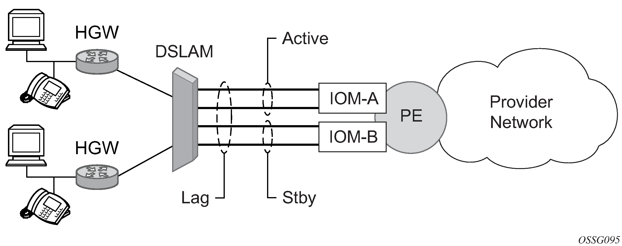
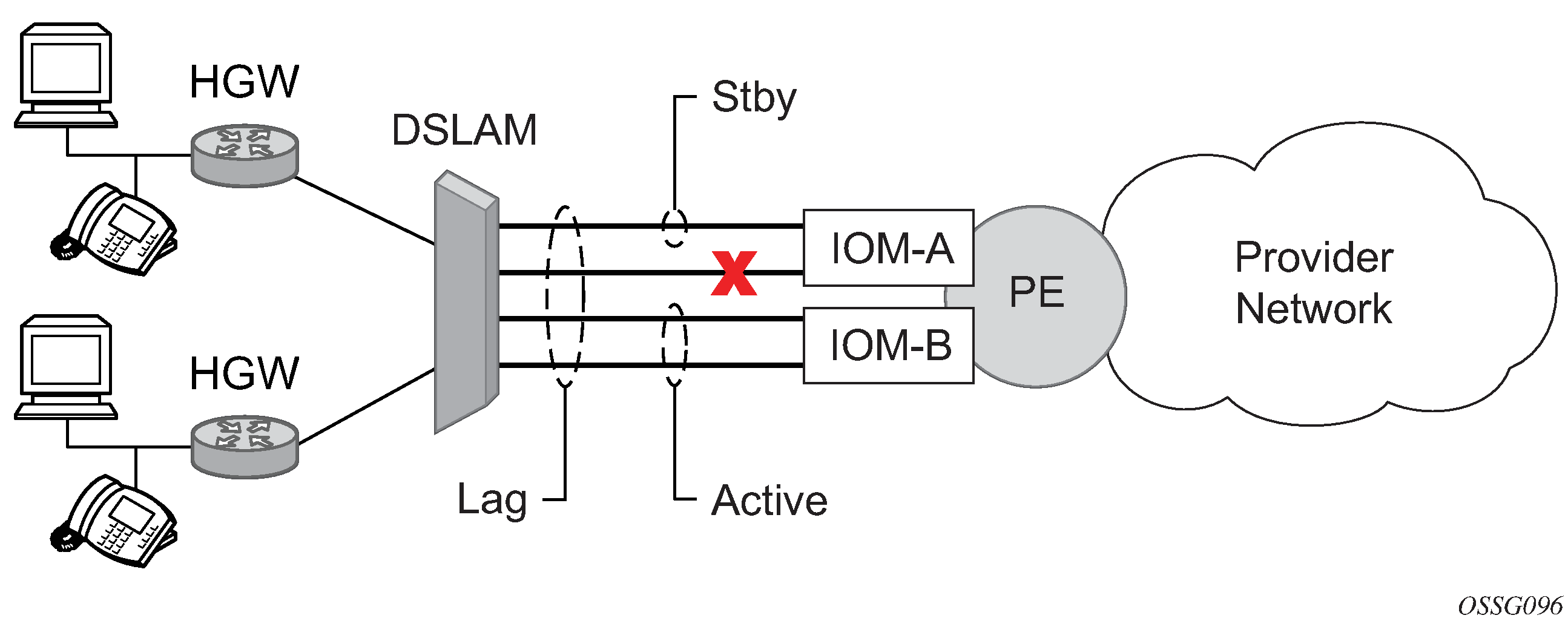
Active/standby LAG operation deployment examples shows how LAG in active/standby mode can be deployed toward a DSLAM access using sub-groups with auto-iom sub-group selection. LAG links are divided into two sub-groups (one per line card).
In case of a link failure, as shown in LAG on access interconnection and LAG on access failure switchover, the switch over behavior ensures that all LAG-members connected to the same IOM as failing link become standby and LAG-members connected to other IOM become active. This way, QoS enforcement constraints are respected, while the maximum of available links is used.
Traffic load balancing options
When a requirement exists to increase the available bandwidth for a logical link that exceeds the physical bandwidth or add redundancy for a physical link, typically one of two methods is applied: equal cost multi-path (ECMP) or Link Aggregation (LAG). A system can deploy both at the same time using ECMP of two or more Link Aggregation Groups (LAG) or single links, or both.
Different types of hashing algorithms can be employed to achieve one of the following objectives:
ECMP and LAG load balancing should be influenced solely by the offered flow packet. This is referred to as per-flow hashing.
ECMP and LAG load balancing should maintain consistent forwarding within a specific service. This is achieved using consistent per-service hashing.
LAG load balancing should maintain consistent forwarding on egress over a single LAG port for a specific network interface, SAP, and so on. This is referred as per link hashing (including explicit per-link hashing with LAG link map profiles). Note that if multiple ECMP paths use a LAG with per-link hashing, the ECMP load balancing is done using either per flow or consistent per service hashing.
These hashing methods are described in the following subsections. Although multiple hashing options may be configured for a specific flow at the same time, only one method is selected to hash the traffic based on the following decreasing priority order:
For ECMP load balancing:
Consistent per-service hashing
Per-flow hashing
For LAG load balancing:
LAG link map profile
Per-link hash
Consistent per-service hashing
Per-flow hashing
Per-flow hashing
Per-flow hashing uses information in a packet as an input to the hash function ensuring that any specific flow maps to the same egress LAG port/ECMP path. Note that because the hash uses information in the packet, traffic for the same SAP/interface may be sprayed across different ports of a LAG or different ECMP paths. If this is not wanted, other hashing methods described in this section can be used to change that behavior. Depending on the type of traffic that needs to be distributed into an ECMP or LAG, or both, different variables are used as input to the hashing algorithm that determines the next hop selection. The following describes default per-flow hashing behavior for those different types of traffic:
VPLS known unicast traffic is hashed based on the IP source and destination addresses for IP traffic, or the MAC source and destination addresses for non-IP traffic. The MAC SA/DA are hashed and then, if the Ethertype is IPv4 or IPv6, the hash is replaced with one based on the IP source address/destination address.
VPLS multicast, broadcast and unknown unicast traffic.
Traffic transmitted on SAPs is not sprayed on a per-frame basis, but instead, the service ID selects ECMP and LAG paths statically.
Traffic transmitted on SDPs is hashed on a per packet basis in the same way as VPLS unicast traffic. However, per packet hashing is applicable only to the distribution of traffic over LAG ports, as the ECMP path is still chosen statically based on the service ID.
Data is hashed twice to get the ECMP path. If LAG and ECMP are performed on the same frame, the data is hashed again to get the LAG port (three hashes for LAG). However, if only LAG is performed, then hashing is only performed twice to get the LAG port.
Multicast traffic transmitted on SAPs with IGMP snooping enabled is load-balanced based on the internal multicast ID, which is unique for every (s,g) record. This way, multicast traffic pertaining to different streams is distributed across different LAG member ports.
The hashing procedure that used to be applied for all VPLS BUM traffic would result in PBB BUM traffic being sent out on BVPLS SAP to follow only a single link when MMRP was not used. Therefore, traffic flooded out on egress BVPLS SAPs is now load spread using the algorithm described above for VPLS known unicast.
Unicast IP traffic routed by a router is hashed using the IP SA/DA in the packet.
MPLS packet hashing at an LSR is based on the whole label stack, along with the incoming port and system IP address. Note that the EXP/TTL information in each label is not included in the hash algorithm. This method is referred to as Label-Only Hash option and is enabled by default, or can be re-instated in CLI by entering the lbl-only option. A few options to further hash on the headers in the payload of the MPLS packet are also provided.
VLL traffic from a service access point is not sprayed on a per-packet basis, but as for VPLS flooded traffic, the service ID selects one of the ECMP/LAG paths. The exception to this is when shared-queuing is configured on an Epipe SAP, or Ipipe SAP, or when H-POL is configured on an Epipe SAP. In those cases, traffic spraying is the same as for VPLS known unicast traffic. Packets of the above VLL services received on a spoke SDP are sprayed the same as for VPLS known unicast traffic.
Note that Cpipe VLL packets are always sprayed based on the service-id in both directions.
Multicast IP traffic is hashed based on an internal multicast ID, which is unique for every record similar to VPLS multicast traffic with IGMP snooping enabled.
If the ECMP index results in the selection of a LAG as the next hop, then the hash result is hashed again and the result of the second hash is input to the modulo like operation to determine the LAG port selection.
When the ECMP set includes an IP interface configured on a spoke SDP (IES/VPRN spoke interface), or a Routed VPLS spoke SDP interface, the unicast IP packets—which is sprayed over this interface—is not further sprayed over multiple RSVP LSPs/LDP FEC (part of the same SDP), or GRE SDP ECMP paths. In this case, a single RSVP LSP, LDP FEC next-hop or GRE SDP ECMP path is selected based on a modulo operation of the service ID. In case the ECMP path selected is a LAG, the second round of the hash, hashes traffic based on the system, port or interface load-balancing settings.
In addition to the above described per-flow hashing inputs, the system supports multiple options to modify default hash inputs.
Layer 4 load balancing
Users can enable Layer 4 load balancing to include TCP/UDP source/destination port numbers in addition to source/destination IP addresses in per-flow hashing of IP packets. By including the Layer 4 information, a SA/DA default hash flow can be sub-divided into multiple finer-granularity flows if the ports used between a specific SA/DA vary.
Layer 4 load balancing can be enabled or disabled at the system or interface level to improve load balancing distribution by including the TCP or UDP source and destination port of the packet to the hash function.
Use the following command to enable layer 4 load balancing at the system level.
configure system load-balancing l4-load-balancingThis setting applies to unicast traffic.
System IP load balancing
This option, when enabled, enhances all per-flow load balancing by adding the system IP address to the hash calculation. This capability avoids polarization of flows when a packet is forwarded through multiple routers with a similar number of ECMP/LAG paths.
Use the following command to enable system IP address load balancing.
configure system load-balancing system-ip-load-balancingSource-only/destination-only hash inputs
A user can include only the source command option or only the destination command option in the hash for inputs that have source/destination context (such as IP address and Layer 4 port). Command options that do not have source/destination context (such as TEID or System IP, for example) are also included in hash as per applicable hash configuration. The functionality ensures that both upstream and downstream traffic hash to the same ECMP path/LAG port on system egress when traffic is sent to a hair-pinned appliance (by configuring source-only hash for incoming traffic on upstream interfaces and destination-only hash for incoming traffic on downstream interfaces).
Use the source and destination command options in the following commands to enable source-only or destination-only hash inputs in load balancing at the Layer 3 interface (service or router) level:
- MD-CLI
configure router interface load-balancing ip-load-balancing configure service vprn interface load-balancing ip-load-balancing configure service ies interface load-balancing ip-load-balancing - classic
CLI
configure router interface load-balancing egr-ip-load-balancing
configure service vprn interface load-balancing egr-ip-load-balancing
configure service ies interface load-balancing egr-ip-load-balancing
Enhanced eLER load balancing
When the user enables the enhanced eLER load balancing option on the egress PEs, load balancing of non-IP traffic over the LAG SAP uses the outer MPLS label stack.
configure system load-balancing eler-enh-load-balancingThe egress PE load-balances non-IP traffic incoming on the network interface using the following options:
- the hash label if the hash label is present in the MPLS label stack
LAG port hash weight
The LAG port hash-weight command customizes the flow hashing distribution between LAG ports by adjusting the weight of each port independently for both same-speed and mixed-speed LAGs.
The following are common rules for using the LAG port hash-weight command.
The configured hash-weight value per port is ignored until the hash-weight command is configured for all the ports in the LAG.
The hash-weight value can be set to port-speed or an integer value from 1 to 100000:
-
port-speed
This assigns an implicit hash-weight value based on the physical port speed.
-
1 to 100000
This value range allows for control of flow hashing distribution between LAG ports.
-
The LAG port hash-weight value is normalized internally to distribute flows between LAG ports. The minimum value returned by this normalization is 1.
When the LAG port hash-weight command is not configured, the value defaults to the port-speed value.
The following table lists the hash-weight values using port-speed per physical port types.
| Port type | Port speed |
|---|---|
| FE port | port-speed value 1 |
| 1GE port | port-speed value 1 |
| 10GE port | port-speed value 10 |
| 25GE port | port-speed value 25 |
| 40GE port | port-speed value 40 |
| 50GE port | port-speed value 50 |
| 100GE port | port-speed value 100 |
| 400GE port | port-speed value 400 |
| 800GE port | port-speed value 800 |
| Other ports | port-speed value 1 |
The LAG port hash-weight capability is supported for both same-speed and mixed-speed LAGs.
Configurable hash weight to control flow distribution
The user can use the LAG port hash-weight to control traffic distribution between LAG ports by adjusting the weight of each port independently.
This capability is especially useful when LAG links on Nokia routers are rate limited by a third-party transport operator providing the connectivity between two sites, as shown in the following figure, where:
-
LAG links 1/1/1 and 1/1/2 are GE
-
LAG link 1/1/1 is rate limited to 300 Mb/s by a third-party transport user
-
LAG Link 1/1/2 is rate limited to 500 Mb/s by a third-party transport user
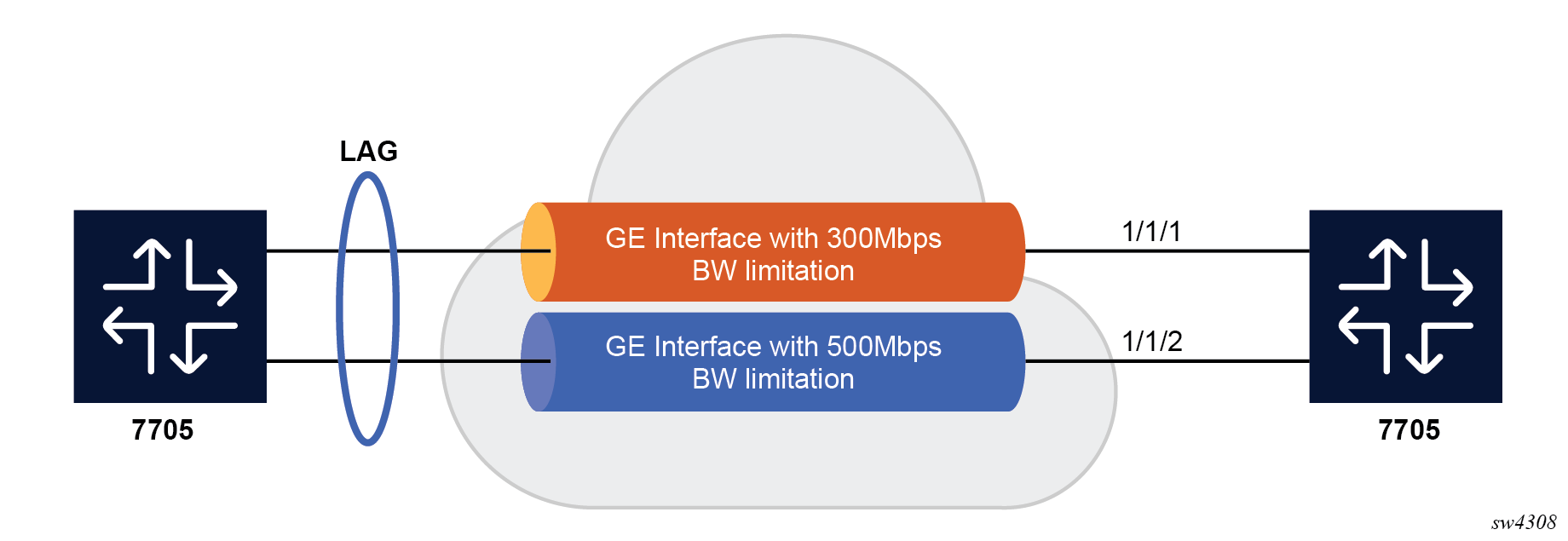
In this context, configure the LAG to adapt the flow distribution between LAG ports according to the bandwidth restrictions on each port that uses customized hash-weight values.
MD-CLI
[ex:/configure lag "lag-5"]
A:admin@node-2# info
    admin-state enable
    port 1/1/1 {
        hash-weight 300
    }
    port 1/1/2 {
        hash-weight 500
    }
classic CLI
A:node-2>config>lag# info
----------------------------------------------
        port 1/1/1 hash-weight 300
        port 1/1/2 hash-weight 500
        no shutdown
----------------------------------------------
Use the following command to display the resulting flow-distribution between active LAG ports.
show lag 3 flow-distribution===============================================================================
Distribution of allocated flows
===============================================================================
Port Bandwidth (Gbps) Hash-weight Flow-share (%)
-------------------------------------------------------------------------------
1/1/1 10.000 300 37.50
1/1/2 10.000 500 62.50
-------------------------------------------------------------------------------
Total operational bandwidth: 20.000
===============================================================================
-
If all ports have a hash-weight configured, other than port-speed, the configured value is used and normalized to modify the hashing between LAG ports.
-
If the LAG ports are all configured to port-speed, or if only some of the ports have a customized hash-weight value, the system uses a hash weight of 1 for every port. For mixed-speed LAGs, the system uses the port-speed value.
Mixed-speed LAGs
Combining ports of different speeds in the same LAG is supported, in service, by adding or removing ports of different speeds.
The different combinations of physical port speeds supported in the same LAG are as follows:
-
1GE and 10GE
-
10GE
The following applies to mixed-speed LAGs:
-
Traffic is load balanced proportionally to the hash-weight value.
-
Both LACP and non-LACP configurations are supported. With LACP enabled, LACP is unaware of physical port speed differences.
-
QoS is distributed according to the following command.
By default, the hash-weight value is taken into account.configure qos adv-config-policy child-control bandwidth-distribution internal-scheduler-weight-mode -
When sub-groups are used, consider the following behavior for selection criteria:
-
highest-count
The highest-count criteria continues to operate on physical link counts. Therefore, a sub-group with lower speed links is selected even if its total bandwidth is lower. For example, a 4 * 10GE sub-group is selected over a 100GE + 10 GE sub-group.
-
highest-weight
The highest-weight criteria continues to operate on user-configured priorities. Therefore, it is expected that configured weights take into account the proportional bandwidth difference between member ports to achieve the wanted behavior. For example, to favor sub-groups with higher bandwidth capacity but lower link count in a 1GE/10GE LAG, set the priority for 10GE ports to a value that is at least 10 times that of the 1GE ports priority value.
-
best-port
The best-port criteria continues to operate on user-configured priorities. Therefore, it is expected that the configured weights take into account proportional bandwidth difference between member ports to achieve the intended behavior.
-
The following are feature limitations for mixed-speed LAGs:
- The PIM lag-usage-optimization command is not supported and must not be configured.
-
LAG member links require the default configuration for egress or ingress rates. Use the following commands to configure the rates:
- MD-CLI
configure port ethernet egress rate configure port ethernet ingress rate - classic
CLI
configure port ethernet egress-rate
configure port ethernet ingress-rate
- MD-CLI
-
ESM is not supported.
-
The following applies to LAN and WAN port combinations in the same LAG:
-
100GE LAN with 10GE WAN is supported.
-
100GE LAN with both 10GE LAN and 10GE WAN is supported.
-
Mixed 10GE LAN and 10GE WAN is supported.
-
The following ports do not support a customized LAG port hash-weight value other than port-speed and are not supported in a mixed-speed LAG:
-
VSM ports
-
10/100 FE ports
-
ESAT ports
-
PXC ports
Adaptive load balancing
Adaptive load balancing (ALB) can be enabled per LAG to resolve traffic imbalance dynamically between LAG member ports. The following can cause traffic distribution imbalance between LAG ports:
-
hashing limitations in the presence of large flows
-
flow bias or service imbalance leading to more traffic over specific ports
ALB actively monitors the traffic rate of each LAG member port and identifies if an optimization is possible to distribute traffic more evenly between LAG ports. The traffic distribution remains flow-based with packets of the same flow egressing a single port of the LAG. The traffic rate of each LAG port is polled at regular intervals, and an optimization is executed only if the ALB tolerance threshold is reached and the minimum bandwidth of the most loaded link in the LAG exceeds the defined bandwidth threshold.
The interval (measured in seconds) for polling LAG statistics from the line cards is configurable. The system optimizes traffic distribution after two polling intervals.
The tolerance is a configurable percentage value corresponding to the difference between the most and least loaded ports in the LAG. The following formula is used to calculate the tolerance:
Using a LAG of two ports as an example, where port A = 10 Gb/s and port B = 8 Gb/s, the difference between the most and least loaded ports in the LAG is equal to the following: (10 - 8) / 10 * 100 = 20%.
The bandwidth threshold defines the minimum bandwidth threshold, expressed in percentage, of the most loaded LAG port egress before ALB optimization is performed.
-
The bandwidth threshold default value is 10% for PXC LAG and 30% for other LAG.
-
ALB is not supported in combination with the configuration of per-link hashing, mixed-speed LAG, customized hashing weights, per FP egress queuing, per FP SAP instances, or ESM.
-
Contact your Nokia technical support representative for more information about scaling when:
- MD-CLI
- more than 16 ports per LAG are used in combination with the max-ports command configured to 64
- more than 8 ports per LAG are used in combination with the max-ports command configured to 32
- classic CLI
- more than 16 ports per LAG are used in combination with LAGs with ID one to 64
- more than 8 ports per LAG are used in combination with LAGs with ID 65 to 800
- MD-CLI
The following example shows an ALB configuration.
MD-CLI
[ex:/configure lag "lag-1"]
A:admin@node-2# info
    encap-type dot1q
    mode access
    adaptive-load-balancing {
        tolerance 20
    }
    port 1/1/1 {
    }
    port 1/1/2 {
    }
classic CLI
A:node-2>config>lag# info
----------------------------------------------
        mode access
        encap-type dot1q
        port 1/1/1
        port 1/1/2
        adaptive-load-balancing tolerance 20
        no shutdown
----------------------------------------------
Consistent per-service hashing
The hashing feature described in this section applies to traffic going over LAG, Ethernet tunnels (eth-tunnel) in load-sharing mode, or CCAG load balancing for VSM redundancy. The feature does not apply to ECMP.
Per-service-hashing was introduced to ensure consistent forwarding of packets belonging to one service. The feature can be enabled using the per-service-hashing command under the following contexts and is valid for Epipe, VPLS, PBB Epipe, IVPLS, BVPLS, EVPN-VPWS and EVPN-VPLS.
configure service epipe load-balancing
configure service vpls load-balancing
The following behavior applies to the usage of the per-service-hashing option.
-
The setting of the PBB Epipe or I-VPLS children dictates the hashing behavior of the traffic destined for or sourced from an Epipe or I-VPLS endpoint (PW/SAP).
-
The setting of the B-VPLS parent dictates the hashing behavior only for transit traffic through the B-VPLS instance (not destined for or sourced from a local I-VPLS or Epipe children).
The following algorithm describes the hash-key used for hashing when the per-service-hashing option is enabled:
-
If the packet is PBB encapsulated (contains an I-TAG Ethertype) at the ingress side and enters a B-VPLS service, use the ISID value from the I-TAG. For PBB encapsulated traffic entering other service types, use the related service ID.
-
If the packet is not PBB encapsulated at the ingress side:
-
For regular (non-PBB) VPLS and Epipe services, use the related service ID.
-
If the packet is originated from an ingress IVPLS or PBB Epipe SAP:
-
If there is an ISID configured, use the related ISID value.
-
If there is no ISID configured, use the related service ID.
-
-
For BVPLS transit traffic use the related flood list ID.
-
Transit traffic is the traffic going between BVPLS endpoints.
-
An example of non-PBB transit traffic in BVPLS is the OAM traffic.
-
-
-
The above rules apply to Unicast, BUM flooded without MMRP or with MMRP, IGMP snooped regardless of traffic type.
Users may sometimes require the capability to query the system for the link in a LAG or Ethernet tunnel that is currently assigned to a specific service-id or ISID.
Use the following command to query the system for the link in a LAG or Ethernet tunnel that is currently assigned to a specific service-id or ISID.
tools dump map-to-phy-port lag 11 service 1ServiceId ServiceName ServiceType Hashing Physical Link
---------- ------------- -------------- ----------------------- -------------
1 i-vpls per-service(if enabled) 3/2/8
A:Dut-B# tools dump map-to-phy-port lag 11 isid 1
ISID Hashing Physical Link
-------- ----------------------- -------------
1 per-service(if enabled) 3/2/8
A:Dut-B# tools dump map-to-phy-port lag 11 isid 1 end-isid 4
ISID Hashing Physical Link
-------- ----------------------- -------------
1 per-service(if enabled) 3/2/8
2 per-service(if enabled) 3/2/7
3 per-service(if enabled) 1/2/2
4 per-service(if enabled) 1/2/3
ESM
In ESM, egress traffic can be load balanced over LAG member ports based on the following entities:
-
per subscriber, in weighted and non-weighted mode
-
per Vport, on non HSQ cards in weighted and non-weighted
-
per secondary shaper on HSQ cards
-
per destination MAC address when ESM is configured in a VPLS (Bridged CO)
ESM over LAGs with configured PW ports require additional considerations:
-
PW SAPs are not supported in VPLS services or on HSQ cards. This means that load balancing per secondary shaper or destination MAC are not supported on PW ports with a LAG configured under them.
-
Load balancing on a PW port associated with a LAG with faceplate member ports (fixed PW ports) can be performed per subscriber or Vport.
-
Load balancing on a FPE (or PXC)-based PW port is performed on two separate LAGs which can be thought of as two stages:
-
Load balancing on a PXC LAG where the subscribers are instantiated. In this first stage, the load balancing can be performed per subscriber or per Vport.
-
The second stage is the LAG over the network faceplate ports over which traffic exits the node. Load balancing is independent of ESM and must be examined in the context of Epipe or EVPN VPWS that is stitched to the PW port.
-
Load balancing per subscriber
Load balancing per subscriber has two modes of operation.
The first mode is native non-weighted per-subscriber load balancing in which traffic is directly hashed per subscriber. Use this mode in SAP and subscriber (1:1) deployments and in SAP and service (N:1) deployments. Examples of services in SAP and services deployments are VoIP, video, or data.
In this mode of operation, the following configuration requirements must be met.
-
Any form of the per-link-hash command in a LAG under the configure lag context must be disabled. This is the default setting.
-
If QoS schedulers or Vports are used on the LAG, their bandwidth must be distributed over LAG member ports in a port-fair operation.
configure lag access adapt-qos port-fairIn this scenario, setting this command option to in adapt-qos to mode link disables per-subscriber load balancing and enables per-Vport load balancing.
configure lag per-link-hash weighted subscriber-hash-mode sapIn this scenario where hashing is performed per SAP, as reflected in the CLI above, in terms of load balancing, per-SAP hashing produces the same results as per-subscriber hashing because SAPs and subscribers are in in a 1:1 relationship. The end result is that the traffic is load balanced per-subscribers, regardless of this indirection between hashing and load-balancing.
With the per-link-hash option enabled, the SAPs (and with this, the subscribers) are dynamically distributed over the LAG member links. This dynamic behavior can be overridden by configuring the lag-link-map-profiles command under the static SAPs or under the msap-policy. This way, each static SAP, or a group of MSAPs sharing the same msap-policy are statically and deterministically assigned to a preordained member port in a LAG.
This mode allows classes and weights to be configured for a group of subscribers with a shared subscriber profile under the following hierarchy.
- MD-CLI
configure subscriber-mgmt sub-profile egress lag-per-link-hash class configure subscriber-mgmt sub-profile egress lag-per-link-hash weight - classic
CLI
configure subscriber-mgmt sub-profile egress lag-per-link-hash class weight
If QoS schedulers and Vports are used on the LAG, their bandwidth should be distributed over LAG member ports in a port-fair operation.
- MD-CLI
configure lag "lag-100" access adapt-qos mode port-fair - classic
CLI
configure lag access adapt-qos port-fair
Load balancing per Vport
Load balancing per Vport applies to user bearing traffic, and not to the control traffic originated or terminated on the BNG, required to setup and maintain sessions, such as PPPoE and DHCP setup and control messages.
Per Vport load balancing has two modes of operation.
In the first mode, non-weighted load balancing based on Vport hashing, the following LAG-related configuration is required.
The per-link-hash command must be disabled.
- MD-CLI
configure lag access adapt-qos mode link - classic
CLI
configure lag access adapt-qos link
If LAG member ports are distributed over multiple forwarding complexes, the following configuration is required.
configure subscriber-mgmt sub-profile vport-hashingThe second mode, weighted load balancing based on Vport hashing, supports class and weight command options per Vport. To enable weighted traffic load balancing per Vport, the following configuration must be enabled.
configure lag per-link-hash weighted subscriber-hash-mode vportThe class and weight can be optionally configured under the Vport definition.
- MD-CLI
configure port ethernet access egress virtual-port lag-per-link-hash class configure port ethernet access egress virtual-port lag-per-link-hash weight - classic
CLI
configure port ethernet access egress vport lag-per-link-hash class weight
Load balancing per secondary shaper
Load balancing based on a secondary shaper is supported only on HSQ cards and only in non-weighted mode. The following LAG-related configuration is required. The per-link-hash command first must be disabled.
- MD-CLI
configure lag "lag-100" access adapt-qos mode link - classic
CLI
configure lag access adapt-qos link
Use the following command to disable per-link-hash.
- MD-CLI
configure lag delete per-link-hash - classic
CLI
configure lag no per-link-hash
Load balancing per destination MAC
This load balancing mode is supported only when ESM is enabled in VPLS in Bridged Central Office (CO) deployments. In this mode of operation, the following configuration is required. The per-link-hash command first must be disabled.
configure subscriber-mgmt msap-policy vpls-only-sap-parameters mac-da-hashing
configure service vpls sap sub-sla-mgmt mac-da-hashing
QoS consideration for access LAG
The following section describes various QoS related features applicable to LAG on access.
Adapt QoS modes
Link Aggregation is supported on the access side with access or hybrid ports. Similarly to LAG on the network side, LAG on access aggregates Ethernet ports into all active or active/standby LAG. The difference with LAG on networks lies in how the QoS or H-QoS is handled. Based on hashing configured, a SAP’s traffic can be sprayed on egress over multiple LAG ports or can always use a single port of a LAG. There are three user-selectable modes that allow the user to best adapt QoS configured to a LAG the SAPs are using:
-
distribute (default)
Use the following command to configure the distributed mode:- MD-CLI
configure lag access adapt-qos mode distribute - classic
CLI
configure lag access adapt-qos distribute
In the distribute mode, the SLA is divided among all line cards proportionate to the number of ports that exist on that line card for a specific LAG. For example, a 100 Mb/s PIR with 2 LAG links on IOM A and 3 LAG links on IOM B would result in IOM A getting 40 Mb/s PIR and IOM B getting 60 Mb/s PIR. Because of this distribution, SLA can be enforced. The disadvantage is that a single flow is limited to IOM’s share of the SLA. This mode of operation may also result in underrun because of hashing imbalance (traffic not sprayed equally over each link). This mode is best suited for services that spray traffic over all links of a LAG.
- MD-CLI
-
link
Use the following command to configure the link mode:- MD-CLI
configure lag access adapt-qos mode link - classic
CLI
configure lag access adapt-qos link
In a link mode the SLA is provided to each port of a LAG. With the example above, each port would get 100 Mb/s PIR. The advantage of this method is that a single flow can now achieve the full SLA. The disadvantage is that the overall SLA can be exceeded, if the flows span multiple ports. This mode is best suited for services that are guaranteed to hash to a single egress port.
- MD-CLI
-
port-fair
Use the following command to configure the port-fair mode:- MD-CLI
configure lag access adapt-qos mode port-fair - classic
CLI
configure lag access adapt-qos port-fair
Port-fair distributes the SLA across multiple line cards relative to the number of active LAG ports per card (in a similar way to distribute mode) with all LAG QoS objects parented to scheduler instances at the physical port level (in a similar way to link mode). This provides a fair distribution of bandwidth between cards and ports whilst ensuring that the port bandwidth is not exceeded. Optimal LAG utilization relies on an even hash spraying of traffic to maximize the use of the schedulers' and ports' bandwidth. With the example above, enabling port-fair would result in all five ports getting 20 Mb/s.
When port-fair mode is enabled, per-Vport hashing is automatically disabled for subscriber traffic such that traffic sent to the Vport no longer uses the Vport as part of the hashing algorithm. Any QoS object for subscribers, and any QoS object for SAPs with explicitly configured hashing to a single egress LAG port, are given the full bandwidth configured for each object (in a similar way to link mode). A Vport used together with an egress port scheduler is supported with a LAG in port-fair mode, whereas it is not supported with a distribute mode LAG.
- MD-CLI
-
distribute include-egr-hash-cfg
Use the following commands to configure the distributed include-egr-hash-cfg mode:- MD-CLI
configure lag access adapt-qos mode distribute configure lag access adapt-qos include-egr-hash-cfg - classic
CLI
configure lag access adapt-qos distribute include-egr-hash-cfg
This mode can be considered a mix of link and distributed mode. The mode uses the configured hashing for LAG/SAP/service to choose either link or distributed adapt-qos modes. The mode allows:
-
SLA enforcement for SAPs that through configuration are guaranteed to hash to a single egress link using full QoS per port (as per link mode)
-
SLA enforcement for SAPs that hash to all LAG links proportional distribution of QoS SLA amongst the line cards (as per distributed mode)
-
SLA enforcement for multi service sites (MSS) that contain any SAPs regardless of their hash configuration using proportional distribution of QoS SLA amongst the line cards (as per distributed mode)
- MD-CLI
The following restrictions apply to adapt-qos distributed include-egr-hash-cfg:
LAG mode must be access or hybrid.
When link-map-profiles or per-link-hash is configured, the user cannot change from include-egr-hash-cfg mode to distribute mode.
The user cannot change from link to include-egr-hash-cfg on a LAG with any configuration.
Adapt QoS bandwidth/rate distribution shows examples of rate/BW distributions based on the adapt-qos mode used.
| distribute | link | port-fair | distribute include-egr-hash-cfg | |
|---|---|---|---|---|
SAP Queues |
% # local links1 | 100% rate |
100% rate (SAP hash to one link) or %# all links2 (SAP hash to all links) |
100% rate (SAP hash to one link) or % # local linksa (SAP hash to all links) |
SAP Scheduler |
% # local linksa |
100% bandwidth |
100% rate (SAP hash to one link) or %# all linksb (SAP hash to all links) |
100% bandwidth (SAP hash to a one link) or % # local linksa (SAP hash to all links) |
SAP MSS Scheduler |
% # local linksa |
100% bandwidth |
% # local linksa |
% # local linksa |
Per-fp-ing-queuing
Per-fp-ing-queuing optimization for LAG ports provides the ability to reduce the number of hardware queues assigned on each LAG SAP on ingress when the flag at LAG level is set for per-fp-ing-queuing.
When the feature is enabled in the configure lag access context, the queue allocation for SAPs on a LAG are optimized and only one queuing set per ingress forwarding path (FP) is allocated instead of one per port.
The following rules apply for configuring the per-fp-ing-queuing at LAG level:
-
To enable per-fp-ing-queuing, the LAG must be in access mode.
-
The LAG mode cannot be set to network mode when the feature is enabled.
-
Per-fp-ing-queuing can only be set if no port members exists in the LAG.
Per-fp-egr-queuing
Per-fp-egr-queuing optimization for LAG ports provides the ability to reduce the number of egress resources consumed by each SAP on a LAG, and by any encap groups that exist on those SAPs.
When the feature is enabled in the configure lag access context, the queue and virtual scheduler allocation are optimized. Only one queuing set and one H-QoS virtual scheduler tree per SAP/encap group is allocated per egress forwarding path (FP) instead of one set per each port of the LAG. In case of a link failure/recovery, egress traffic uses failover queues while the queues are moved over to a newly active link.
Per-fp-egr-queuing can be enabled on existing LAG with services as long as the following conditions are met.
-
The mode of the LAG must be access or hybrid.
-
The port-type of the LAGs must be standard.
-
The LAG must have either per-link-hash enabled or all SAPs on the LAG must use per-service-hashing only and be of a type: VPLS SAP, i-VPLS SAP, or e-Pipe VLL or PBB SAP.
To disable per-fp-egr-queuing, all ports must first be removed from a specific LAG.
Per-fp-sap-instance
Per-fp-sap-instance optimization for LAG ports provides the ability to reduce the number of SAP instance resources consumed by each SAP on a lag.
When the feature is enabled, in the config>lag>access context, a single SAP instance is allocated on ingress and on egress per each forwarding path instead of one per port. Thanks to an optimized resource allocation, the SAP scale on a line card increases, if a LAG has more than one port on that line card. Because SAP instances are only allocated per forwarding path complex, hardware reprogramming must take place when as result of LAG links going down or up, a SAP is moved from one LAG port on a specific line card to another port on a specific line card within the same forwarding complex. This results in an increased data outage when compared to per-fp-sap-instance feature being disabled. During the reprogramming, failover queues are used when SAP queues are reprogrammed to a new port. Any traffic using failover queues is not accounted for in SAPs statistics and is processed at best-effort priority.
The following rules apply when configuring a per-fp-sap-instance on a LAG:
Per-fp-ing-queuing and per-fp-egr-queuing must be enabled.
The functionality can be enabled/disabled on LAG with no member ports only. Services can be configured.
Other restrictions:
SAP instance optimization applies to LAG-level. Whether a LAG is sub-divided into sub-groups or not, the resources are allocated per forwarding path for all complexes LAG’s links are configured on (that is irrespective of whether a sub-group a SAP is configured on uses that complex or not).
Egress statistics continue to be returned per port when SAP instance optimization is enabled. If a LAG links are on a single forwarding complex, all ports but one have no change in statistics for the last interval – unless a SAP moved between ports during the interval.
Rollback that changes per-fp-sap-instance configuration is service impacting.
LAG hold-down timers
Users can configure multiple hold-down timers that allow control how quickly LAG responds to operational port state changes. The following timers are supported:
-
port-level hold-time up/down timer
This optional timer allows user to control delay for adding/removing a port from LAG when the port comes UP/goes DOWN. Each LAG port runs the same value of the timer, configured on the primary LAG link. See the Port Link Dampening description in Port features for more details on this timer.
-
sub-group-level hold-time timer
This optional timer allows user to control delay for a switch to a new candidate sub-group selected by LAG sub-group selection algorithm from the current, operationally UP sub-group. The timer can also be configured to never expire, which prevents a switch from operationally up sub-group to a new candidate sub-group (manual switchover is possible using tools perform force lag command). Note that, if the port link dampening is deployed, the port level timer must expire before the sub-group-selection takes place and this timer is started. Sub-group-level hold-down timer is supported with LAGs running LACP only.
-
LAG-level hold-time down timer
This optional timer allows user to control delay for declaring a LAG operationally down when the available links fall below the required port/BW minimum. The timer is recommended for LAG connecting to MC-LAG systems. The timer prevents a LAG going down when MC-LAG switchover executes break-before-make switch. Note that, if the port link dampening is deployed, the port level timer must expire before the LAG operational status is processed and this timer is started.
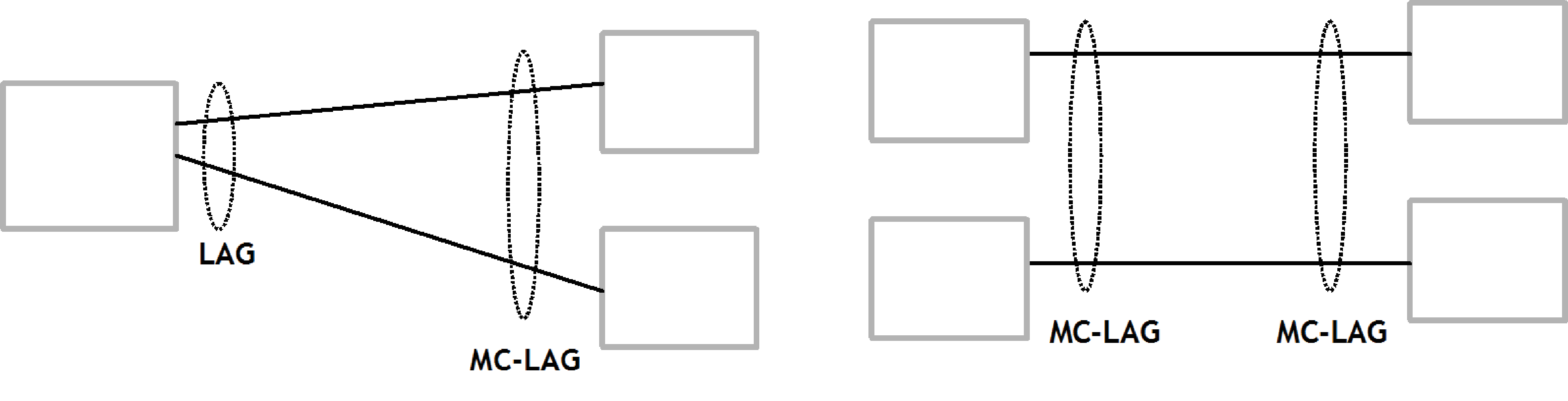
Multi-Chassis LAG
Multi-Chassis LAG (MC-LAG) is an extension of the LAG concept. MC-LAG provides node-level redundancy, in addition to the link-level redundancy provided by LAG.
Typically, MC-LAG is deployed in a network-wide scenario providing redundant connection between different end points. The whole scenario is then built by combination of different mechanisms (for example, MC-LAG and redundant pseudowire to provide e2e redundant p2p connection or dual homing of DSLAMs in Layer 2/3 TPSDA).
Overview
Multichassis LAG is a method of providing redundant Layer 2/3 access connectivity that extends beyond link level protection by allowing two systems to share a common LAG end point.
The multiservice access node (MSAN) node is connected with multiple links toward a redundant pair of Layer 2/3 aggregation nodes such that both link and node level redundancy, are provided. By using a multichassis LAG protocol, the paired Layer 2/3 aggregation nodes (referred to as redundant-pair) appears to be a single node utilizing LACP toward the access node. The multichassis LAG protocol between a redundant-pair ensures a synchronized forwarding plane to and from the access node and synchronizes the link state information between the redundant-pair nodes such that correct LACP messaging is provided to the access node from both redundant-pair nodes.
To ensure SLAs and deterministic forwarding characteristics between the access and the redundant-pair node, MC-LAG provides an active/standby operation to and from the access node. LACP is used to manage the available LAG links into active and standby states, which ensures that links from only one aggregation node are active at a time to and from the access node.
configure lag standby-signaling power-offThe selection of the common system ID, system-priority, and administrative-key are used in LACP messages so that partner systems consider all links as part of the same LAG.
The selection algorithm is extended to allow the selection of the active sub-group.
A sub-group definition in the LAG context is local to the single box, which means that if sub-groups configured on two different systems have the same sub-group-id, they are still considered two separate sub-groups within the specified LAG.
Multiple sub-groups per PE in an MC-LAG are supported.
In the case where there is a tie in the selection algorithm, (for example, two sub-groups with identical aggregate weight (or number of active links), the group that is local to the system with the lower system LACP priority and LAG system ID is used.
An inter-chassis communication channel allows LACP support on both systems. The inter-chassis communication channel supports the following:
Connections at the IP level that do not require a direct link between two nodes. The IP address configured at the neighbor system is one of the addresses of the system (interface or loop-back IP address).
A communication protocol that provides a heartbeat mechanism to enhance the robustness of the MC-LAG operation and to detect node failures.
User actions on any node that force an operational change.
LAG group-ids that do not have to match between neighbor systems. At the same time, there can be multiple LAG groups between the same pair of neighbors.
Verifying the configuration of physical characteristics, such as speed and auto-negotiation, and initiating user notifications (traps) if errors exist. Consistency of MC-LAG configuration (system-id, administrative-key, and system-priority) is provided. Similarly, the load-balancing mode of operation must be consistently configured on both nodes.
Traffic over the signaling link encryption using a user-configurable message digest key.
MC-LAG provides active/standby status to other software applications to build a reliable solution.
MC-LAG Layer 2 dual-homing to remote PE pairs and MC-LAG Layer 2 dual homing to local PE pairs show the different combinations of MC-LAG attachments that are supported. The supported configurations can be sub-divided into following sub-groups:
-
Dual-homing to remote PE pairs
-
both end-points attached with MC-LAG
-
one end-point attached
-
-
Dual-homing to local PE pair
-
both end-points attached with MC-LAG
-
one end-point attached with MC-LAG
-
both end-points attached with MC-LAG to two overlapping pairs
-
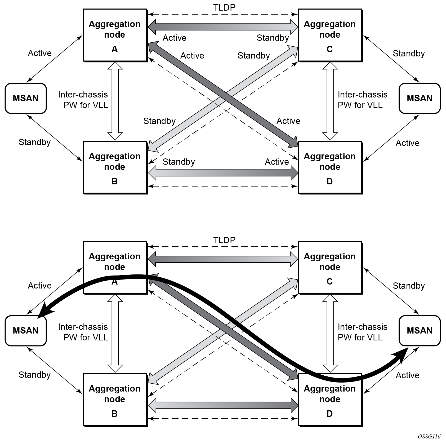
The forwarding behavior of the nodes abide by the following principles. Note that logical destination (actual forwarding decision) is primarily determined by the service (VPLS or VLL) and the principle below applies only if destination or source is based on MC-LAG:
-
Packets received from the network are forwarded to all local active links of the specific destination-sap based on conversation hashing. In case there are no local active links, the packets are cross-connected to inter-chassis pseudowire.
-
Packets received from the MC-LAG sap are forwarded to active destination pseudowire or active local links of destination-sap. In case there are no such objects available at the local node, the packets are cross-connected to inter-chassis pseudowire.
MC-LAG and SRRP
MC-LAG and Subscriber Routed Redundancy Protocol (SRRP) enable dual-homed links from any IEEE 802.1ax (formerly 802.3ad) standards-based access device (for example, a IP DSLAM, Ethernet switch or a Video on Demand server) to multiple Layer 2/3 or Layer 3 aggregation nodes. In contrast with slow recovery mechanisms such as Spanning Tree, multichassis LAG provides synchronized and stateful redundancy for VPN services or triple play subscribers in the event of the access link or aggregation node failing, with zero impact to end users and their services.
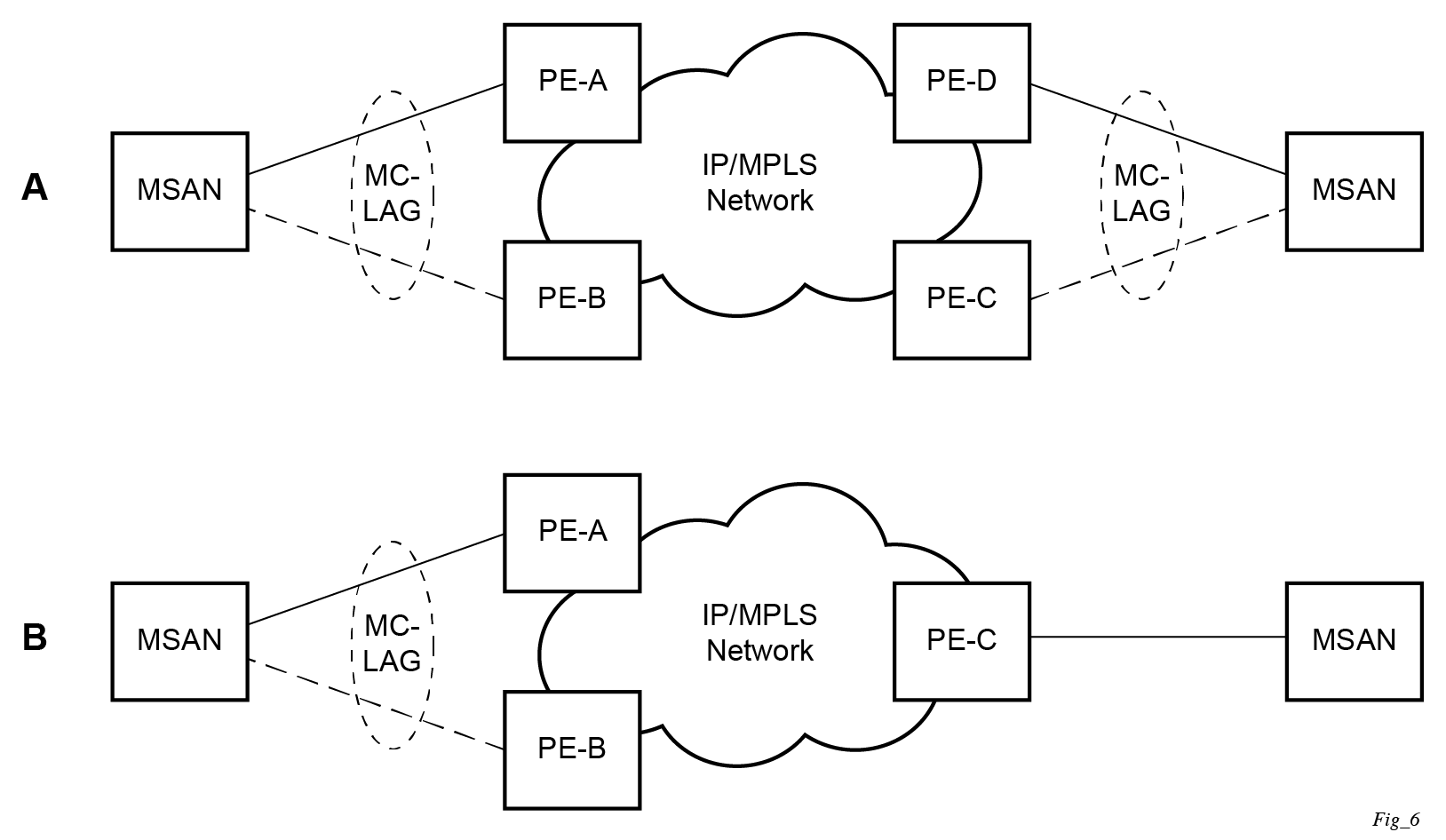
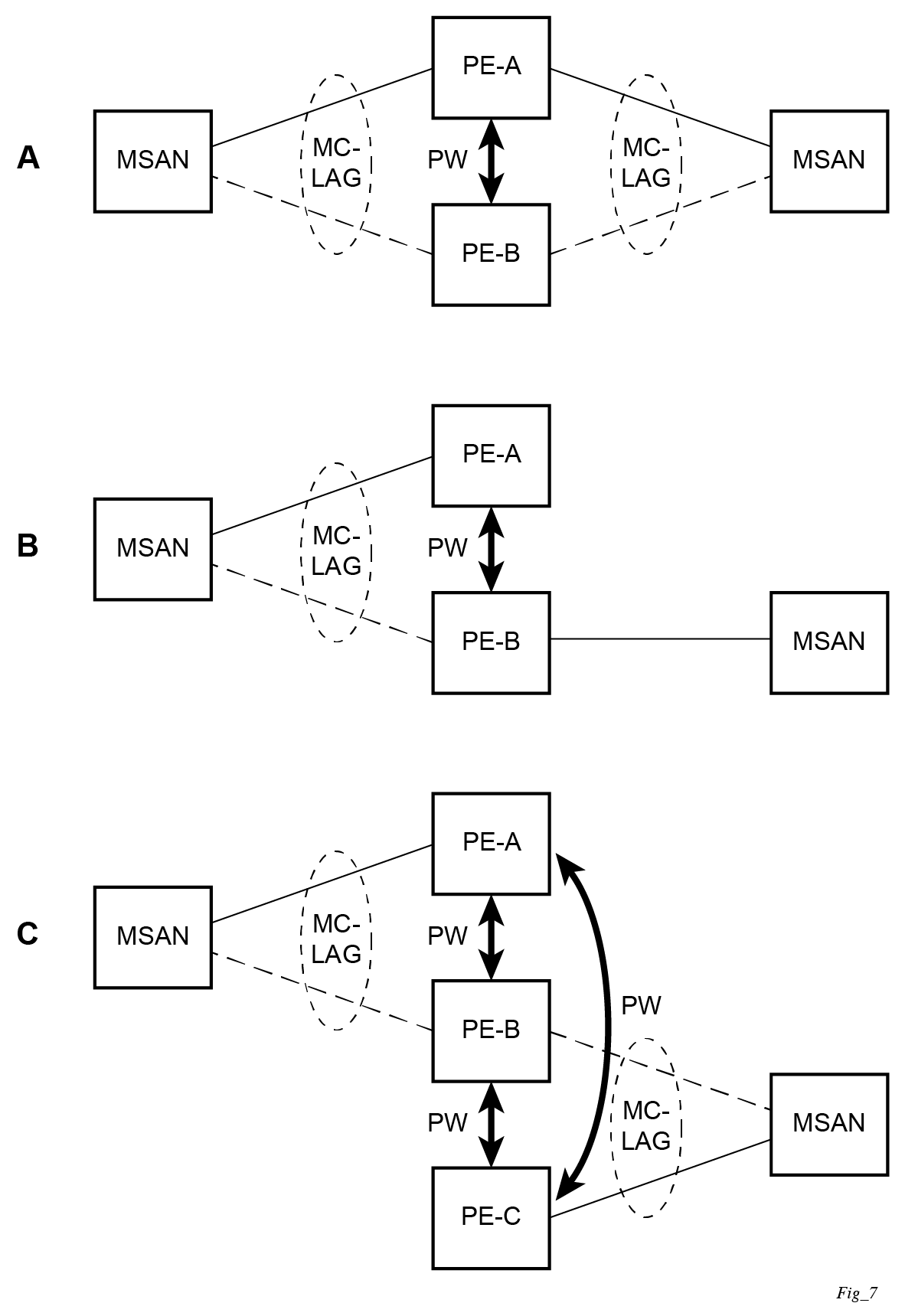
P2P redundant connection across Layer 2/3 VPN network
Point-to-Point (P2P) redundant connection through a Layer 2 VPN network shows the connection between two multiservice access nodes (MSANs) across a network based on Layer 2/3 VPN pseudowires. The connection between MSAN and a pair of PE routers is realized by MC-LAG. From an MSAN perspective, a redundant pair of PE routers acts as a single partner in LACP negotiation. At any time, only one of the routers has an active link in a specified LAG. The status of LAG links is reflected in status signaling of pseudowires set between all participating PEs. The combination of active and stand-by states across LAG links as well as pseudowires gives only one unique path between a pair of MSANs.
Note that the configuration in Point-to-Point (P2P) redundant connection through a Layer 2 VPN network shows one particular configuration of VLL connections based on MC-LAG, particularly the VLL connection where two ends (SAPs) are on two different redundant-pairs. In addition to this, other configurations are possible, such as:
Both ends of the same VLL connections are local to the same redundant-pair.
One end VLL endpoint is on a redundant-pair the other on single (local or remote) node.
DSLAM dual-homing in a Layer 2/3 TPSDA model
The following figure shows a network configuration where DSLAM is dual-homed to a pair of redundant PEs by using MC-LAG. In the aggregation network, a redundant pair of PEs is connecting to a VPLS service, which provides a reliable connection to a single or pair of Broadband Service Routers (BSRs).
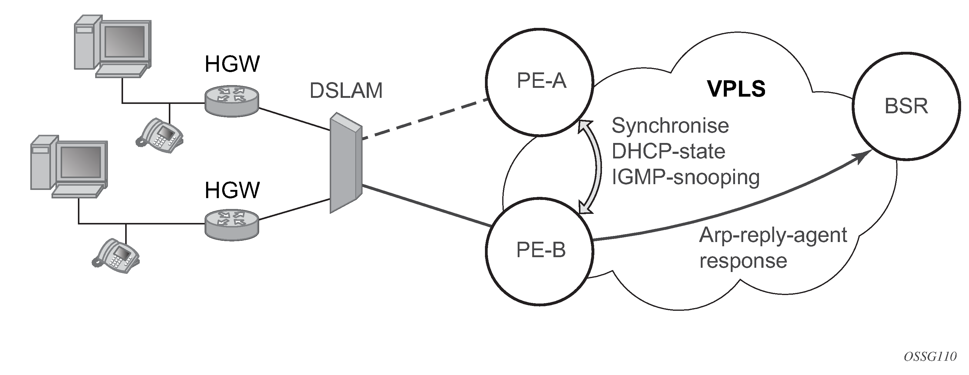
MC-LAG and pseudowire connectivity, PE-A and PE-B implement enhanced subscriber management features based on DHCP-snooping and creating dynamic states for every subscriber-host. As in any point of time there is only one PE active, it is necessary to provide the mechanism for synchronizing subscriber-host state-information between active PE (where the state is learned) and stand-by PE. In addition, VPLS core must be aware of active PE to forward all subscriber traffic to a PE with an active LAG link. The mechanism for this synchronization is outside of the scope of this document.
LAG port and hash-weight thresholds
The following sections provide information on LAG port and hash-weight thresholds.
LAG IGP cost
When using a LAG, it is possible to take an operational link degradation into consideration by setting a configurable degradation threshold. The following alternative settings are available through configuration:
configure lag port-threshold
configure lag hash-weight-threshold
When the LAG operates under normal circumstances and is included in an IS-IS or OSPF routing instance, the LAG must be associated with an IGP link cost. This LAG cost can either be statically configured in the IGP context or set dynamically by the LAG based upon the combination of the interface speed and reference bandwidth.
Under operational LAG degradation however, it is possible for the LAG to set a new updated dynamic or static threshold cost taking the gravity of the degradation into consideration.
As a consequence, there are some IGP link cost alternatives available, for which the most appropriate must be selected. The IGP uses the following priority rules to select the most appropriate IGP link cost:
-
Static LAG cost (from the LAG threshold action during degradation)
-
Explicit configured IGP cost (from the configuration under the IGP routing protocol context)
-
Dynamic link cost (from the LAG threshold action during degradation)
-
Default metric (no cost is set anywhere)
For example:
-
Static LAG cost overrules the configured metric.
-
Dynamic cost does not overrule configured metric or static LAG cost.
Adjusting the operational state of the LAG
Instead of changing the IGP cost, when using a LAG, a user can also configure to take the operational state of the links or link degradation into consideration to adjust the operational state of the LAG. Use the action command option of the following command to control the operational state of the LAG:
- MD-CLI
configure lag string port-threshold - classic
CLI
configure lag lag-id port-threshold
When the total number of operational links for the LAG is at or below the configured threshold value, the LAG operational state is brought down. If the number of operational links for the LAG exceeds the threshold value, the operational state of LAG is brought up.
For LAGs with PXC sub-ports also the operational state can be controlled through the port-threshold action down configuration described in the preceding information.
Similar to port threshold, use the hash-weight threshold to control the operational state of the LAG. Use the action option in the following the command to control the operational state of the LAG:
- MD-CLI
configure lag string hash-weight-threshold - classic
CLI
configure lag lag-id hash-weight-threshold
When the sum of hash weights of all the operational links of LAG is at or below the configured threshold value (weight), the LAG operational state is brought down. If the sum of hash weights of all operational LAG links exceeds the hash-weight threshold value, the operational state of LAG is brought up.