Ports
Port types
Before a port can be configured, the slot must be provisioned with a card type and MDA type.
Nokia routers support the following port types:
-
Ethernet
Supported Ethernet port types include:
-
Fast Ethernet (100BASE-T)
-
Gb Ethernet (1GbE, 1000BASE-T)
-
10 Gb Ethernet (10GbE, 10GBASE-X)
Router ports must be configured as either access, hybrid, or network. The default is network.
-
-
access
Access ports are configured for customer facing traffic on which services are configured. If a Service Access Port (SAP) is to be configured on the port or channel, it must be configured as an access port or channel. When a port is configured for access mode, the appropriate encapsulation type must be configured to distinguish the services on the port or channel. After a port has been configured for access mode, one or more services can be configured on the port or channel depending on the encapsulation value.
-
network
Network ports are configured for network-facing traffic. These ports participate in the service provider transport or infrastructure network. Dot1q is supported on network ports.
-
hybrid
Hybrid ports are configured for access and network-facing traffic. While the default mode of an Ethernet port remains network, the mode of a port cannot be changed between the access, network, and hybrid values unless the port is shut down and the configured SAPs or interfaces are deleted. Hybrid ports allow a single port to operate in both access and network modes. The MTU of a port in hybrid mode is the same as in network mode, except for the 10/100 MDA. The default encapsulation for hybrid port mode is dot1q; it also supports QinQ encapsulation on the port level. Null hybrid port mode is not supported. After the port is changed to hybrid, the default MTU of the port is changed to match the value of 9212 bytes currently used in network mode (higher than an access port). This is to ensure that both SAP and network VLANs can be accommodated. The only exception is when the port is a 10/100 Fast Ethernet. In those cases, the MTU in hybrid mode is set to 1522 bytes, which corresponds to the default access MTU with QinQ, which is larger than the network dot1q MTU or access dot1q MTU for this type of Ethernet port. The configuration of all command options in access and network contexts continues to be done within the port using the same CLI hierarchy as in existing implementation. The difference is that a port configured in mode hybrid allows both ingress and egress contexts to be configured concurrently. An Ethernet port configured in hybrid mode can have two values of encapsulation type: dot1q and QinQ. The NULL value is not supported because a single SAP is allowed, and can be achieved by configuring the port in the access mode, or a single network IP interface is allowed, which can be achieved by configuring the port in network mode. Hybrid mode can be enabled on a LAG port when the port is part of a single chassis LAG configuration. When the port is part of a multichassis LAG configuration, it can only be configured to access mode because MC-LAG is not supported on a network port and consequently is not supported on a hybrid port. The same restriction applies to a port that is part of an MC-Ring configuration.
For a hybrid port, use the following commands to split the amount of allocated port buffers in each ingress and egress equally between network and access contexts:
-
MD-CLI
configure port hybrid-buffer-allocation ingress-weight access network configure port hybrid-buffer-allocation egress-weight access network -
classic CLI
configure port hybrid-buffer-allocation ing-weight access network
configure port hybrid-buffer-allocation egr-weight access network
Adapting the terminology in buffer-pools, the port’s access active bandwidth and network active bandwidth in each ingress and egress are derived as follows (egress formulas shown only):
-
total-hybrid-port-egress-weights = access-weight + network-weight
-
hybrid-port-access-egress-factor = access-weight / total-hybrid-port-egress-weights
-
hybrid-port-network-egress-factor = network-weight / total-hybrid-port-egress-weights
-
port-access-active-egress-bandwidth = port-active-egress-bandwidth x
-
hybrid-port-access-egress-factor
-
port-network-active-egress-bandwidth = port-active-egress-bandwidth x
-
hybrid-port-network-egress-factor
-
-
WAN PHY
10 G Ethernet ports can be configured in WAN PHY mode. Use commands in the following context to configure 10 G Ethernet ports in WAN PHY mode.
configure port ethernet xgigWhen configuring the port to be in WAN mode, you can change specific SONET/SDH command options to reflect the SONET/SDH requirements for this port.
-
SONET-SDH and TDM
Supported SONET-SDH and TDM port types include:
-
DS-1/E-1 channel
-
OC3/STM-1
-
OC12/STM-4
-
-
Link Aggregation (LAG)
LAG can be used to group multiple ports into one logical link. The aggregation of multiple physical links allows for load sharing and offers seamless redundancy. If one of the links fails, traffic is redistributed over the remaining links.
-
Automatic Protection Switching (APS)
Automatic Protection Switching (APS) is a means to provide redundancy on SONET equipment to guard against linear unidirectional or bidirectional failures. The network elements (NEs) in a SONET/SDH network constantly monitor the health of the network. When a failure is detected, the network proceeds through a coordinated pre-defined sequence of steps to transfer (or switchover) live traffic to the backup facility (called protection facility.) This is done very quickly to minimize lost traffic. Traffic remains on the protection facility until the primary facility (called working facility) fault is cleared, at which time the traffic may optionally be reverted to the working facility.
-
Optical Transport Network (OTN)
Including OTU2, OTU2e, OTU3, and OTU4. OTU2 encapsulates 10-Gigabit Ethernet WAN and adds FEC (Forward Error Correction). OTU2e encapsulates 10-Gigabit Ethernet LAN and adds FEC (Forward Error Correction). OTU4 encapsulates 100-Gigabit Ethernet and adds FEC.
-
connector
A QSFP28 (or QSFP-DD) connector that can accept transceiver modules including breakout connectors to multiple physical ports. For example, a QSFP28 connector can support ten 10 Gb Ethernet ports. The connectors themselves cannot be used as ports in other commands, however, the breakout ports can be used as any Ethernet port.
Ethernet ports
This section provides information about the support Ethernet port and pluggable transceiver types for 7705 SAR Gen 2 platforms.
The following table lists the supported speeds for pluggable transceiver types.
| Pluggable transceiver type | Supported speeds |
|---|---|
| SFP |
SFP transceivers support speeds of 1 Gb/s, unless 100 Mb/s support is noted in other table footnotes. |
| SFP+ | SFP+ transceivers support speeds of 10 Gb/s. |
| 7705 SAR Gen 2 hardware |
Physical port type |
Accepted pluggable transceivers | |
|---|---|---|---|
| SFP | SFP+ | ||
| 7705 SAR-1 | SFP | ✓ | |
| SFP+ | ✓ | ✓ | |
Port features
Port State and Operational State
There are two port attributes that are related and similar but have slightly different meanings: Port State and Operational State (or Operational Status).
The following descriptions are based on normal individual ports. Many of the same concepts apply to other objects that are modeled as ports in the router such as APS groups but the show output descriptions for these objects should be consulted for the details.
-
Port State
-
Displayed in port summaries such as show port or show port 1/1
-
tmnxPortState in the TIMETRA-PORT-MIB
-
Values: None, Ghost, Down (linkDown), Link Up, Up
-
-
Operational State
-
Displayed in the show output of a specific port such as show port 2/1/3
-
tmnxPortOperStatus in the TIMETRA-PORT-MIB
-
Values: Up (inService), Down (outOfService)
-
The behavior of Port State and Operational State are different for a port with link protocols configured (for example, LACP for Ethernet ports). A port with link protocols configured only transitions to the Up Port State when the physical link is up and all the configured protocols are up. A port with no link protocols configured transitions from Down to Link Up and then to Up immediately after the physical link layer is up.
The linkDown and linkUp log events (events 2004 and 2005 in the SNMP application group) are associated with transitions of the port Operational State. Note that these events map to the RFC 2863, The Interfaces Group MIB, (which obsoletes RFC 2233, The Interfaces Group MIB using SMIv2) linkDown and linkUp traps as mentioned in the SNMPv2-MIB.
An Operational State of Up indicates that the port is ready to transmit service traffic (the port is physically up and any configured link protocols are up). The relationship between port Operational State and Port State is shown in Relationship of Port state and Oper state.
|
Port state |
Operational state (Oper state or Oper status) (as displayed in ‟show port x/y/z”) | |
|---|---|---|
|
Port State (as displayed in the show port summary) |
For ports that have no link layer protocols configured |
For ports that have link layer protocols configured (PPP, LACP, 802.3ah EFM, 802.1ag Eth-CFM) |
|
Up |
Up |
Up |
|
Link Up (indicates the physical link is ready) |
Up |
Down |
|
Down |
Down |
Down |
Exponential Port Dampening
Exponential Port Dampening (EPD) provides the ability to automatically block a port from reuse for a period of time after physical link-down and physical link-up events. If a series of down-up events occur close together, EPD keeps the port’s operational state down for a longer period than if only one down-up event has occurred. The router avoids using that port if external events are causing the link state to fluctuate. The more events that occur, the longer the port is kept down and avoided by the routing protocols.
EPD behavior uses a fixed penalty amount per link-down event and a half-life decay equation to reduce these penalties over time. The following equation defines exponential decay:
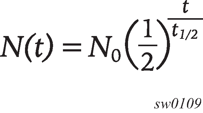
where:
N(t) is the quantity that still remains after a time t
N0 is the initial quantity
t½ is the half-life
In dampening, N0 refers to the starting penalties from the last link-down event. The quantity N(t) refers to the decayed penalties at a specific time, and is calculated starting from the last link-down event (that is, from the time when N0 last changed).
This equation can also be used on a periodic basis by updating the initial quantity value N0 each period and then computing the new penalty over the period (t).
The following figure shows an example usage of the EDP feature.
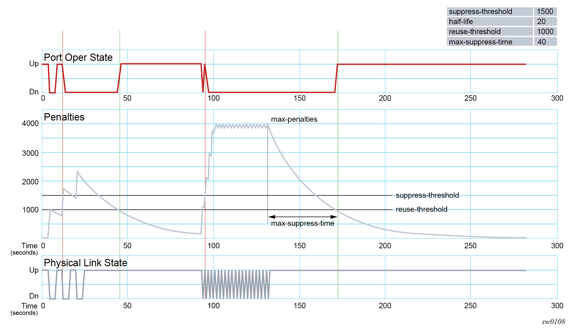
At time (t = 0) in the preceding figure, the initial condition has the link up, the accumulated penalties are zero, the dampening state is idle, and the port operational state is up. The following series of events and actions occur.
t = 5: link-down event
the accumulated penalties are incremented by 1000
the accumulated penalties now equal 1000, which is less than the suppress threshold (of 1500), so the dampening state is idle
because the dampening state is idle, link-down is passed to the upper layer
link-down triggers the port operational state to down
t = 9: link-up event
the accumulated penalties equal 869, which is less than the suppress threshold, so the dampening state remains as idle
because the dampening state is idle, link-up is passed to the upper layer
link-up triggers the port operational state to up
t = 13: link-down event
the accumulated penalties are incremented by 1000
the accumulated penalties now equal 1755, which is greater than the suppress threshold, so the dampening state is changed to active
because the dampening state just transitioned to active, link-down is passed to the upper layer
link-down triggers the port operational state to down
t = 17: link-up event
the accumulated penalties equal 1527, which is above the reuse threshold (of 1000) and greater than the suppress threshold, so the dampening state remains as active
because the dampening state is active, link-up is not passed to the upper layer
the port operational state remains down
t = 21: link-down event
the accumulated penalties are incremented by 1000
the accumulated penalties now equal 2327, which is above the reuse threshold, so the dampening state remains as active
because the dampening state is active, link-down is not passed to the upper layer
the port operational state remains down
t = 25: link-up event
the accumulated penalties equal 2024, which is above the reuse threshold, so dampening state remains as active
because the dampening state is active, link-up is not passed to the upper layer
the port operational state remains down
t = 46: accumulated penalties drop below the reuse threshold
the accumulated penalties drop below the reuse threshold, so the dampening state changes to idle
because the dampening state is idle and the current link state is up, link-up is passed to the upper layer
the port operational state changes to up
t = 94 to 133: link-down and link-up events every second
similar to previous events, the accumulated penalties increment on every link-down event
the dampening state transitions to active at t = 96, and link state events are not sent to the upper layer after that time
the upper layer keeps the port operational state down after t = 96
the accumulated penalties increment to a maximum of 4000
t = 133: final link event of link-up
the accumulated penalties equal 3863
the dampening state remains active and link state events are not sent to the upper layer
the upper layer keeps the port operational state down
t = 172: accumulated penalties drop below the reuse threshold
the accumulated penalties drop below the reuse threshold, so the dampening state changes to idle
because the dampening state is idle and the current link state is up, link-up is passed to the upper layer
the port operational state changes to up
Forward Error Correction
Users can use Forward Error Correction (FEC) on some ports to improve either the transmission reliability or reach, or both. FEC must always be used on some interface types while it is optional for other interface types. Also, some interface types allow more than one type of FEC. No matter what the setting of the FEC attributes, the transmitter and the receiver must have the same configuration, or the link will not work. The setting of FEC on a specific port is dependent on the interface type and the specific optical transceiver in use.
For coherent optics, the FEC (host and media) do not need to be configured and are automatically inherited and enabled based on the specific module and configured coherent mode of operation.
Contact your Nokia representative for information about the options based on the transceiver in use.