System management
This chapter provides information about configuring basic system management parameters.
System management commands
System management commands allow you to configure basic system management functions, such as the system name, contact, router location and coordinates, as well as time zones, Network Time Protocol (NTP), Simple Network Time Protocol (SNTP) synchronization, Precision Time Protocol (PTP), and CRON.
System information
This section describes the system information components.
Name
You can configure a name for the system device. The name is used in the prompt string. Only one system name can be configured. If multiple system names are configured the last one encountered overwrites the previous entry. Use the following command to configure the system name.
configure system nameContact
Use the contact command to specify the name of a system administrator, IT staff member, or other administrative entity.
Use the following command to configure the contact.
configure system contactLocation
Use the location command to specify the location of the device. For example, enter the city, building address, floor, room number, and so on, where the router is located.
Use the following command to configure the location.
configure system locationCoordinates
You can optionally configure the GPS location of the device. If the string contains special characters (#, $, spaces, and so on), the entire string must be enclosed within double quotes. Use the following command to configure the system coordinates.
configure system coordinatesNaming objects
Avoid configuring named objects with a name that starts with ‟_tmnx_” and with ‟_” in general.
Common language location identifier
A Common Language Location Identifier (CLLI) for the device is an 11-character standardized code string that uniquely identifies the geographic location of places and specific functional categories of equipment unique to the telecommunications industry. The CLLI code is stored in the Nokia Chassis MIB tmnxChassisCLLICode object.
The CLLI code can be any ASCII printable text string of up to 11 characters.
DNS security extensions
DNS Security (DNSSEC) Extensions are now implemented in the SR OS, allowing operators to configure DNS behavior of the router to evaluate whether the Authenticated Data bit was set in the response received from the recursive name server and to trust the response, or ignore it.
System time
Routers are equipped with a real-time system clock for timekeeping purposes. When set, the system clock always operates on Coordinated Universal Time (UTC), but the software has options for local time translation as well as system clock synchronization.
Time zones
Setting a time zone in SR OS allows for times to be displayed in the local time rather instead of UTC. SR OS has both user-defined and system-defined time zones.
A user-defined time zone has a user-assigned name of up to four printable ASCII characters in length and is unique from the system-defined time zones. For user-defined time zones, the offset from UTC is configured as well as any summer time adjustment for the time zone.
configure system time prefer-local-timeTime strings include the following:
- log filenames and log header information
- times in rollback information
- times in rollback and configuration files header information
- times related to CRON scripts
- times related to CRON scripts
- times in the event handler system
- times in NETCONF and gRPC date-and-time leafs
configure log log-id time-formatThe SR OS system-defined time zones are listed in the following table, which includes both time zones with and without daylight saving (summer) time adjustment.
| Acronym | Time zone name | UTC offset |
|---|---|---|
Europe: |
||
GMT |
Greenwich Mean Time |
UTC |
BST |
British Summer Time |
UTC +1 |
IST |
Irish Summer Time |
UTC +1* |
WET |
Western Europe Time |
UTC |
WEST |
Western Europe Summer Time |
UTC +1 |
CET |
Central Europe Time |
UTC +1 |
CEST |
Central Europe Summer Time |
UTC +2 |
EET |
Eastern Europe Time |
UTC +2 |
EEST |
Eastern Europe Summer Time |
UTC +3 |
MSK |
Moscow Time |
UTC +3 |
MSD |
Moscow Summer Time |
UTC +4 |
US and Canada: |
||
AST |
Atlantic Standard Time |
UTC -4 |
ADT |
Atlantic Daylight Time |
UTC -3 |
EST |
Eastern Standard Time |
UTC -5 |
EDT |
Eastern Daylight Saving Time |
UTC -4 |
ET |
Eastern Time |
Either as EST or EDT, depending on place and time of year |
CST |
Central Standard Time |
UTC -6 |
CDT |
Central Daylight Saving Time |
UTC -5 |
CT |
Central Time |
Either as CST or CDT, depending on place and time of year |
MST |
Mountain Standard Time |
UTC -7 |
MDT |
Mountain Daylight Saving Time |
UTC -6 |
MT |
Mountain Time |
Either as MST or MDT, depending on place and time of year |
PST |
Pacific Standard Time |
UTC -8 |
PDT |
Pacific Daylight Saving Time |
UTC -7 |
PT |
Pacific Time |
Either as PST or PDT, depending on place and time of year |
HST |
Hawaiian Standard Time |
UTC -10 |
AKST |
Alaska Standard Time |
UTC -9 |
AKDT |
Alaska Standard Daylight Saving Time |
UTC -8 |
Australia and New Zealand: |
||
AWST |
Western Standard Time (for example, Perth) |
UTC +8 hours |
ACST |
Central Standard Time (for example, Darwin) |
UTC +9.5 hours |
AEST |
Eastern Standard/Summer Time (for example, Canberra) |
UTC +10 hours |
NZT |
New Zealand Standard Time |
UTC +12 hours |
NZDT |
New Zealand Daylight Saving Time |
UTC +13 hours |
NTP
NTP is the Network Time Protocol defined in RFC 1305, Network Time Protocol (Version 3) Specification, Implementation and Analysis and RFC 5905, Network Time Protocol Version 4: Protocol and Algorithms Specification. It allows for the participating network nodes to keep time more accurately and more importantly they can maintain time in a more synchronized fashion between all participating network nodes.
SR OS uses an NTP process based on a reference build provided by the Network Time Foundation. Nokia strongly recommends that the users review RFC 8633, Network Time Protocol Best Current Practices, when they plan to use NTP with the router. The RFC section ‟Using Enough Time Sources” indicates that using only two time sources (NTP servers) can introduce instability if they provide conflicting information. To maintain accurate time, Nokia recommends configuring three or more NTP servers.
NTP uses stratum levels to define the number of hops from a reference clock. The reference clock is considered to be a stratum-0 device that is assumed to be accurate with little or no delay. Stratum-0 servers cannot be used in a network. However, they can be directly connected to devices that operate as stratum-1 servers. A stratum-1 server is an NTP server with a directly-connected device that provides Coordinated Universal Time (UTC), such as a GPS or atomic clock.
The higher stratum levels are separated from the stratum-1 server over a network path, therefore, a stratum-2 server receives its time over a network link from a stratum-1 server. A stratum-3 server receives its time over a network link from a stratum-2 server.
SR OS routers normally operate as a stratum-2 or higher device. The router relies on an external stratum-1 server to source accurate time into the network. However, SR OS also allows for the use of the local PTP recovered time to be sourced into NTP. In this latter case, the local PTP source appears as a stratum-0 server and SR OS advertises itself as a stratum-1 server. Activation of the PTP source into NTP may impact the network NTP topology because the SR OS router is promoted to stratum-1.
SR OS router runs a single NTP clock which then operates NTP message exchanges with external NTP clocks. Exchanges can be made with external NTP clients, servers, and peers. These exchanges can be through the base, management, or VPRN routing instances.
NTP operates associations between clocks as either client or server, symmetric active and symmetric passive, or broadcast modes. These modes of operation are applied according to which elements are configured on the router. To run server mode, the operator must enable NTP server mode for the base and each needed VPRN routing instance. To run client mode, the operator must configure external servers. If both the local router and remote router are configured with each other as peers, then the router operates in symmetric active mode. If only one side of the association has peering configured, then the modes are symmetric passive. To operate using broadcast mode, interfaces must be configured to transmit as broadcast servers or receive as broadcast clients.
NTP server operation for both unicast and broadcast communication within a VPRN is configured within the VPRN (see "NTP Within a VPRN Service" in the 7705 SAR Gen 2 Layer 3 Services Guide: IES and VPRN).
The following NTP elements are supported:
-
server mode
In this mode, the node advertises the ability to act as a clock source for other network elements. The node, by default, transmits NTP packets in NTP version 4 mode.
-
authentication keys
Authentication keys implement increased security support in carrier and other networks. Both DES and MD5 authentication are supported, as well as multiple keys.
-
operation in symmetric active mode
This capability requires that NTP be synchronized with a specific node that is considered more trustworthy or accurate than other nodes carrying NTP in the system. This mode requires that a specific peer is set.
-
server and peer addressing using IPv6
Both external servers and external peers may be defined using IPv6 or IPv4 addresses. Other features (such as multicast, broadcast) use IPv4 addressing only.
-
broadcast or multicast modes
When operating in these modes, the node receives or sends using either a multicast (default 224.0.1.1) or a broadcast address. Multicast is supported only on the CPM MGMT port.
-
alert when NTP server is not available
When none of the configured servers are reachable on the node, the system reverts to manual timekeeping and issues a critical alarm. When a server becomes available, a trap is issued indicating that standard operation has resumed.
-
NTP and SNTP
If both NTP and SNTP are enabled on the node, then SNTP transitions to an operationally down state. If NTP is removed from the configuration or shut down, then SNTP resumes an operationally up state.
-
gradual clock adjustment
As several applications (such as Service Assurance Agent (SAA)) can use the clock, and if determined that a major (128 ms or more) adjustment needs to be performed, the adjustment is performed by programmatically stepping the clock. If a minor (less than 128 ms) adjustment must be performed, then the adjustment is performed by either speeding up or slowing down the clock.
-
To avoid the generation of too many events/trap the NTP module rates limit the generation of events/traps to three per second. At that point a single trap is generated that indicates that event/trap squashing is taking place.
CRON
The CRON feature supports periodic and date and time-based scheduling in SR OS. CRON can be used, for example, to schedule Service Assurance Agent (SAA) functions. CRON functionality includes the ability to specify scripts that need to be run, when they are scheduled, including one-time only functionality (one-shot), interval and calendar functions. Scheduled reboots, peer turn ups, service assurance agent tests and more can all be scheduled with CRON, as well as OAM events, such as connectivity checks, or troubleshooting runs.
CRON supports the schedule element. The schedule function configures the type of schedule to run, including one-time only (one-shot), periodic, or calendar-based runs. All runs are determined by month, day of month or weekday, hour, minute, and interval (seconds).
GNSS
The 7705 SAR-Hx and 7705 SAR-Mx support frequency synchronization using a Layer 1 interface, such as Synchronous Ethernet (SyncE), and ToD synchronization using protocols such as NTP or PTP. In cases where these methods are not possible or where accuracy cannot be ensured for the service, you can deploy a GNSS receiver as a synchronous timing source. GNSS data is used to provide network-independent frequency and ToD synchronization.
GNSS receivers on the 7705 SAR-Hx and 7705 SAR-Mx support GPS and Galileo reference using an integrated GNSS RF port.
A 7705 SAR-Hx or 7705 SAR-Mx chassis equipped with a GNSS receiver and an attached GNSS antenna can be configured to receive frequency traceable to Stratum-1 (PRC/PRS). The GNSS receiver provides a synchronization clock to the SSU in the router with the corresponding QL for SSM. This frequency is distributed to the rest of the router from the SSU as configured with the following commands:
- MD-CLI
configure system central-frequency-clock ref-order configure system central-frequency-clock ql-selection - classic
CLI
configure system sync-if-timing ref-order
configure system sync-if-timing ql-selection
If GNSS signal loss or jamming causes timing information to become unavailable, the GNSS receiver automatically prevents the output of clock or synchronization data to the system. In this case, the system can revert to alternate timing sources.With Assisted Partial Timing Support (APTS), the system can perform a seamless switch when reverting to a backup PTP session; see GNSS failure with APTS.
GNSS failure with APTS
When the G.8275.2 profile is used for GNSS-enabled 7705 SAR Gen 2 platforms, the APTS capability frequently measures and stores the delay offset between the GNSS time and a backup PTP session time. If a GNSS failure occurs, the backup PTP session automatically becomes the selected reference for time and frequency, and the stored delay offset value is added to or subtracted from the backup PTP session time to keep time and phase for the router as accurate as possible.
When GNSS has recovered and is stable, the system automatically switches back to GNSS for the time and frequency reference, and backup PTP monitoring and delay measurement resumes.
Network synchronization
This section describes network synchronization capabilities available on 7705 SAR Gen 2 platforms. These capabilities involve multiple approaches to network timing; namely SyncE, Adaptive clocking, and a Precision Time Protocol (PTP) IEEE 1588v2. These features address barriers to entry by:
-
providing the synchronization quality required by the mobile space, such as radio operations and circuit emulation services (CES) transport
-
augmenting and potentially replacing the existing timing infrastructure, and delivering high-quality network timing for frequency and time-sensitive wireline applications
The network time architecture in the following figure shows how network synchronization is commonly distributed in a hierarchical PTP topology at the physical layer.
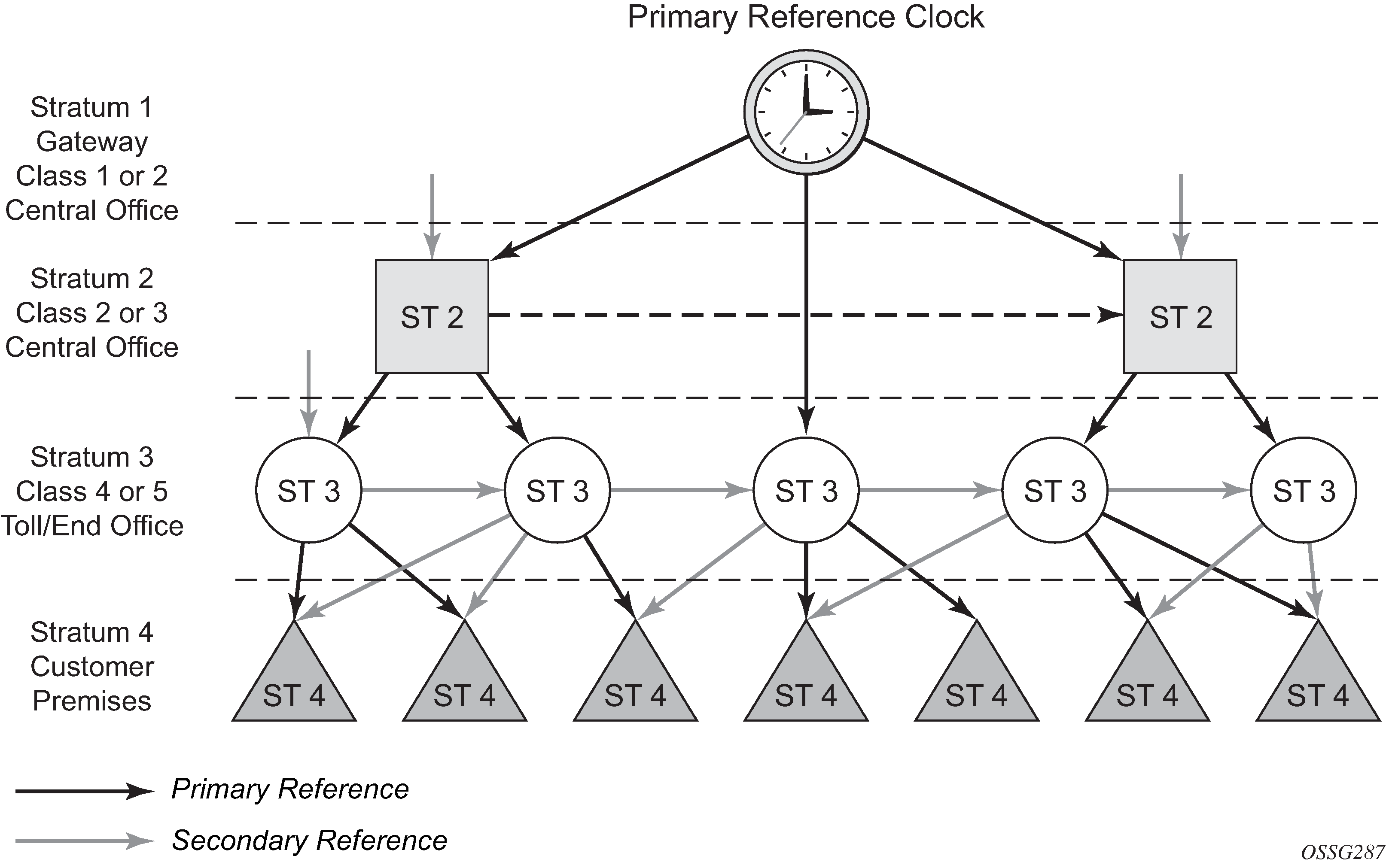
The architecture shown in the preceding figure provides the following benefits:
-
limits the need for high-quality clocks at each network element and only requires reliable and accurate replication of the input to remain traceable to its reference
-
uses reliable physical media to provide transport of the timing signal. It does not consume any bandwidth and requires limited additional processing
The synchronization network is designed so a clock always receives timing from a clock of equal or higher stratum level or quality level (QL). This ensures that if an upstream clock has a fault condition (for example, loses its reference and enters a holdover or free-run state) and begins to drift in frequency, the downstream clock is able to follow it. For greater reliability and robustness, most offices and nodes have at least two synchronization references that can be selected in priority order (such as primary and secondary).
Further levels of resiliency can be provided by designing a capability in the node clock that operates within prescribed network performance specifications in the absence of any reference for a specified period. A clock operating in this mode is said to hold the last known state over (or holdover) until the reference lock is once again achieved. Each level in the timing hierarchy is associated with minimum levels of network performance.
Each synchronization capable port can be independently configured to transmit data using the node reference timing or loop timing.
Specifically for SyncE, transmitting a reference clock through a chain of Ethernet equipment requires that all equipment supports SyncE. A single piece of non-SyncE equipment breaks the chain. Although Ethernet frames still get through, the recovered line timing is not traceable to an acceptable stratum source and downstream devices should not use it.
Central synchronization subsystem
The timing subsystem for platforms has a central clock located on the CPM (motherboard). The timing subsystem performs many duties of the network element clock as defined by Telcordia (GR-1244-CORE) and ITU-T G.781.
The system can select from up to four timing inputs to train the local oscillator. The priority order of these references must be specified. This is a simple ordered list of inputs: {ref1, ref2, ptp, gnss}. The CPM clock output has the ability to drive the clocking for all line cards in the system. The routers support selection of the node reference using QL indications. The following figure shows this selection process.
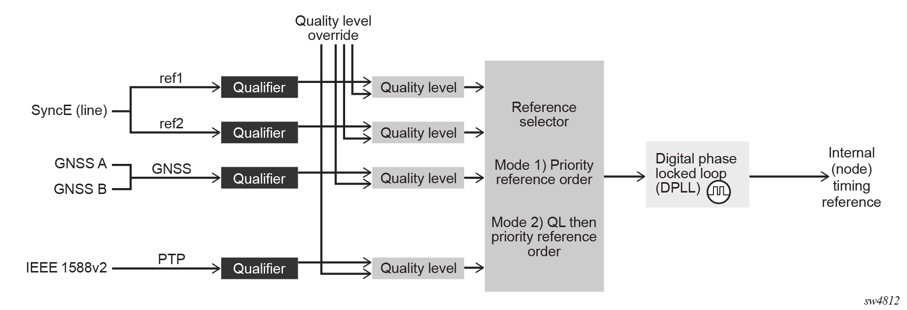
The recovered clock can derive its timing from any of the following:
-
SyncE ports
- GNSS RF ports
-
IEEE 1588v2 timeReceiver port (PTP)
When QL selection mode is disabled, the reversion setting controls when the central clock can reselect a previously failed reference.
The following table lists the selection operation for two references in both revertive and non-revertive modes:
| Status of reference A | Status of reference B | Active reference non-revertive case | Active reference revertive case |
|---|---|---|---|
|
OK |
OK |
A |
A |
|
Failed |
OK |
B |
B |
|
OK |
OK |
B |
A |
|
OK |
Failed |
A |
A |
|
OK |
OK |
A |
A |
|
Failed |
Failed |
holdover |
holdover |
|
OK |
Failed |
A |
A |
|
Failed |
Failed |
holdover |
holdover |
|
Failed |
OK |
B |
B |
|
Failed |
Failed |
holdover |
holdover |
|
OK |
OK |
A or B |
A |
Synchronization Status Messages
Synchronization Status Messages (SSMs) allow the synchronization distribution network to determine the QL of the clock sourcing a specific synchronization trail. This allows a network element (NE) to select the best of multiple input synchronization trails. SSMs have been defined for various transport protocols, including T1/E1 and SyncE, for interaction with office clocks (such as BITS or SSUs) and embedded NE clocks.
SSMs allow equipment to autonomously provision and reconfigure (by reference switching) their synchronization references, while helping to avoid the creation of timing loops. These messages are particularly useful to allow synchronization reconfigurations when timing is distributed in both directions around a ring.
The following sections provide details about the SSM message functionality for different signal types. These functions apply to all platforms that support the signal type.
E1 signals
E1 signals can indicate the QL of the source generating the timing information using the SSM as specified in Recommendation G.704.
One of the Sa4 to Sa8 bits (the actual Sa bit is for user selection) is allocated for SSMs. To prevent ambiguities in pattern recognition, it is necessary to align the first bit (San1) with frame 1 of a G.704 E1 multi-frame.
A San bit is one of a 4-bit nibble, San1 to San4. San1 is the most significant bit; San4 is the least significant bit.
The message set in San1 to San4 is a copy of the set defined in SDH bits 5 to 8 of byte S1.
SyncE
Traditionally, Ethernet-based networks employ the physical layer transmitter clock to be derived from an inexpensive +/-100ppm crystal oscillator and the receiver locks onto it. There is no need for long term frequency stability because the data is packetized and can be buffered. For the same reason there is no need for consistency between the frequencies of different links. However, you can derive the physical layer transmitter clock from a high quality frequency reference by replacing the crystal with a frequency source traceable to a primary reference clock. This would not affect the operation of any of the Ethernet layers, for which this change would be transparent. The receiver at the far end of the link would lock onto the physical layer clock of the received signal, and therefore gain access to a highly accurate and stable frequency reference. Then, in a manner analogous to conventional hierarchical network synchronization, this receiver could lock the transmission clock of its other ports to this frequency reference and a fully time synchronous network could be established.
The advantage of using SyncE compared with methods that rely on sending timing information in packets over an unclocked physical layer, is that it is not influenced by impairments introduced by the higher levels of the networking technology (packet loss, packet delay variation). Hence, the frequency accuracy and stability may be expected to exceed those of networks with unsynchronized physical layers.
SyncE allows users to gracefully integrate existing systems and future deployments into conventional industry-standard synchronization hierarchy. The concept behind SyncE is analogous to SONET/SDH system timing capabilities. It allows the user to select any (optical) Ethernet port as a candidate timing reference. The recovered timing from this port is then used to time the system (for example, the CPM locks to this configured reference selection). The user then could ensure that any of system output would be locked to a stable traceable frequency source.
Fixed copper Ethernet ports in the 1000BASE-T mode of operation depend on the 802.3 link timing for the SyncE functionality, in accordance with recommendations in ITU-T G.8262. The 802.3 link timing states must align with the wanted direction of SyncE timing flow. When a fixed copper Ethernet port is specified as an input reference for the node or when it is removed as an input reference for the node, an 802.3 link auto-negotiation is triggered to ensure the link timing aligns properly.
The SSM of SyncE uses an Ethernet OAM PDU that uses the slow protocol subtype. For a complete description of the format and processing, see ITU-T G.8264.
Timing reference selection based on QL
For a SyncE interface that supports Ethernet Synchronization Message Channel (ESMC), a timing input or PTP clock class provides a QL value to indicate the source of timing of the far-end transmitter. These values provide input to the selection process on the nodal timing subsystem. This selection process determines which input to use to generate the signal on the SSM egress ports and the reference to use to synchronize the nodal clock, as follows:
For the two reference inputs (ref1 and ref2), if the interface configuration supports the reception of a QL over SSM or ESMC, the QL value is associated with the timing derived from that input.
For the two reference inputs, if the interface configuration is T1 with SF framing, the quality level associated with the input is QL-UNKNOWN.
For the two reference inputs, if they are SyncE ports and the ESMC is disabled, the QL value associated with that input is QL-UNKNOWN.
For the two reference inputs, if the interface configuration supports the reception of a QL over SSM (and not ESMC), and no SSM value has been received, the QL value associated with the input is QL-STU.
For the two reference inputs, if the interface configuration supports the reception of a QL over SSM or ESMC, but the QL value received over the interface is not valid for the type of interface, the QL value associated with that input is QL-INVALID.
For the two reference inputs, if they are external synchronization ports, the QL value associated with the input is QL-UNKNOWN.
For the two reference inputs, if they are SyncE ports and the ESMC is enabled, but no valid ESMC Information PDU has been received within the previous 5 s, the QL value associated with that input is QL-FAILED.
For GNSS reference input, the QL is PRS if a frequency is successfully recovered; otherwise, the QL is QL-FAILED.
If the user has configured an override for the QL associated with an input, the node displays both the received and override QL value for the input. If no value has been received, the associated value is displayed instead.
After the QL values have been associated with the system timing inputs, the two reference inputs and the external input timing ports are processed by the system timing module to select a source for the SSU. This selection process is as follows.
- Before an input can be used as a potential timing source, it must be enabled using the following command:
- MD-CLI
configure system central-frequency-clock ql-selection - classic
CLI
configure system sync-if-timing ql-selection
- MD-CLI
configure system central-frequency-clock ref-order - classic
CLI
configure system sync-if-timing ref-order
- MD-CLI
If the ql-selection command is enabled, the priority of the inputs is calculated using the associated QL value of the input and the priority order configured under the ref-order command. The inputs are ordered by the internal relative QL based on their associated QL values. If two or more inputs have the same quality level value, they are placed in order based on where they appear in the ref-order priority. The priority order for the SETG is based on both the reference inputs and the external synchronization input ports.
After a prioritized list of inputs is calculated, the SETG and the external synchronization output ports are configured to use the inputs in their respective orders.
After the SETG and external synchronization output ports priority lists are programmed, the highest-qualified priority input is used. To be qualified, the signal is monitored to ensure that it has the expected format and a frequency that is within the pull-in range of the SETG.
Extended QL TLV for ESMC messaging
SR OS supports the extended QL TLV of the ESMC message as defined in ITU-T G.8264. This TLV allows the communication of newer QL values and some synchronization trail information up to the current clock. The newly added QL values include:
-
QL_ePRTC
-
QL_PRTC
-
QL_PRC
-
QL_eEEC
Clock source QL definitions
The following clock source QLs have been identified for tracking network timing flow. These levels make up all the defined network deployment options described in Recommendation G.803 and G.781. The Option I network is developed on the original European SDH model. The Option II network is developed on the North American SONET model.
In addition to the QL values received over the SSM of an interface, the standards also define additional codes for internal use. These include the following:
-
QL INVx is generated internally by the system if and when an unallocated SSM value is received, where x represents the binary value of this SSM. All independent values are assigned as the single value of QL-INVALID.
-
QL FAILED is generated internally by the system if and when the terminated network synchronization distribution trail is in the signal fail state.
Additionally, QL-UNKNOWN is an internal QL used to differentiate from a received QL-STU code. For the purposes of QL selection, it is considered equivalent.
The following table lists the synchronization message coding and source priorities for SSM received.
| SSM value received on port | Internal relative QL | |||
|---|---|---|---|---|
| SDH interface or SyncE interface in SDH mode | SONET interface or SyncE interface in SONET mode | E1 interface | T1 interface (ESF) | |
|
0010 (prc) |
0001 (prs) |
0010 (prc) |
00000100 11111111 (prs) |
1. Best quality |
|
0000 (stu) |
00001000 11111111 (stu) |
2. |
||
|
0111 (st2) |
00001100 11111111 (ST2) |
3. |
||
|
0100 (ssua) |
0100 (tnc) |
0100 (ssua) |
01111000 11111111 (TNC) |
4. |
|
1101 (st3e) |
01111100 11111111 (ST3E) |
5. |
||
|
1000 (ssub) |
1000 (ssub) |
6. |
||
|
1010 (st3/eec2) |
00010000 11111111 (ST3) |
7. |
||
|
1011 (sec/eec1) |
1011 (sec) |
8. Lowest quality qualified in QL-enabled mode |
||
|
1100 (smc) |
00100010 11111111 (smc) |
9. |
||
|
00101000 11111111 (st4) |
10. |
|||
|
1110 (pno) |
01000000 11111111 (pno) |
11. |
||
|
1111 (dnu) |
1111 (dus) |
1111 (dnu) |
00110000 11111111 (dus) |
12. |
|
Any other |
Any other |
Any other |
N/A |
13. QL_INVALID |
|
14. QL-FAILED |
||||
|
15. QL-UNC |
||||
The following table lists the synchronization message coding and source priorities for SSM transmitted.
| Internal relative QL | SSM values transmitted by interface of type | |||
|---|---|---|---|---|
| SDH interface or SyncE interface in SDH mode | SONET interface or SyncE interface in SONET mode | E1 interface | T1 interface (ESF) | |
|
1. Best quality |
0010 (prc) |
0001 (PRS) |
0010 (prc) |
00000100 11111111 (PRS) |
|
2. |
0100 (ssua) |
0000 (stu) |
0100 (ssua) |
00001000 11111111 (stu) |
|
3. |
0100 (ssua) |
0111 (st2) |
0100 (ssua) |
00001100 11111111 (st2) |
|
4. |
0100 (ssua) |
0100 (tnc) |
0100 (ssua) |
01111000 11111111 (tnc) |
|
5. |
1000 (ssub) |
1101 (st3e) |
1000 (ssub) |
01111100 11111111 (st3e) |
|
6. |
1000 (ssub) |
1010 (st3/eec2) |
1000 (ssub) |
00010000 11111111 (st3) |
|
7. |
1011 (sec/eec1) |
1010 (st3/eec2) |
1011 (sec) |
00010000 11111111 (st3) |
|
8. Lowest quality qualified in QL-enabled mode |
1011 (sec/ eec1) |
1100 (smc) |
1011 (sec) |
00100010 11111111 (smc) |
|
9. |
1111 (dnu) |
1100 (smc) |
1111 (dnu) |
00100010 11111111 (smc) |
|
10. |
1111 (dnu) |
1111 (dus) |
1111 (dnu) |
00101000 11111111 (st4) |
|
11. |
1111 (dnu) |
1110 (pno) |
1111 (dnu) |
01000000 11111111 (pno) |
|
12. |
1111 (dnu) |
1111 (dus) |
1111 (dnu) |
00110000 11111111 (dus) |
|
13. QL_INVALID |
1111 (dnu) |
1111 (dus) |
1111 (dnu) |
00110000 11111111 (dus) |
|
14. QL-FAILED |
1111 (dnu) |
1111 (dus) |
1111 (dnu) |
00110000 11111111 (dus) |
|
15. QL-UNC |
1011 (sec/eec1) |
1010 (st3/eec2) |
1011 (sec) |
00010000 11111111 (st3) |
Advanced G.781 features
The central clock of the node supports several advanced features of the ITU-T G.781 standard. These include the specification of minimum acceptable QL values for the input references and the specification of a Wait To Restore timer for input references. These features allow for more options in the management of the synchronization topology.
IEEE 1588v2 PTP
PTP is a timing-over-packet protocol defined in the IEEE 1588v2 standard 1588 PTP 2008.
PTP may be deployed as an alternative timing-over-packet option to Adaptive Clock Recovery (ACR). PTP provides the capability to synchronize network elements to a Stratum-1 clock or primary reference clock (PRC) traceable frequency source over a network that may or may not be PTP-aware. PTP has several advantages over ACR. It is a standards-based protocol, has lower bandwidth requirements, can transport both frequency and time, and can potentially provide better performance.
Support is provided for an ordinary clock in timeReceiver or timeTransmitter mode or a boundary clock. When configured as an ordinary clock timeTransmitter, PTP can only be used for the distribution of a frequency reference, not a time reference. The boundary clock and ordinary clock timeReceiver can be used for both frequency and time distribution.
The ordinary clock timeTransmitter, ordinary clock timeReceiver, and boundary clock communicate with neighboring IEEE 1588v2 clocks. These neighbor clocks can be ordinary clock timeTransmitters, ordinary clock timeReceivers, or boundary clocks. The communication can be based on either unicast IPv4/IPv6 sessions transported through IP interfaces or multicast Ethernet transported through Ethernet ports.
- MD-CLI
configure system security source-address ipv6 address configure service vprn source-address ipv6 address - classic
CLI
configure system security source-address application6
configure service vprn source-address application6
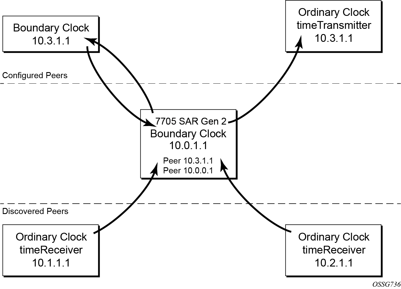
For the unicast IP sessions, the external clocks are labeled "peers". There are two types of peers: configured and discovered. An ordinary clock timeReceiver or a boundary clock should have configured peers for each PTP neighbor clock from which it may accept synchronization information. The router initiates unicast sessions with all configured peers. An ordinary clock timeTransmitter or boundary clock accepts unicast session requests from external peers. If the peer is not a configured peer, then it is considered a discovered peer. An ordinary clock timeTransmitter or boundary clock can deliver synchronization information toward discovered peers. The following figure shows the relationship of various neighbor clocks using unicast IP sessions to communicate with a 7705 SAR Gen 2 configured as a boundary clock with two configured peers.
For multicast Ethernet operation, the router listens for and transmits PTP messages using the configured multicast MAC address. Neighbor clocks are discovered via the reception of messages through an enabled Ethernet port. An ordinary clock timeTransmitter, ordinary clock timeReceiver, and a boundary clock support more than one neighbor PTP clock connecting into a single port. This may be encountered with the deployment of an Ethernet multicast LAN segment between the local clock and the neighbor PTP ports using an end-to-end transparent clock or an Ethernet switch. The Ethernet switch is not recommended because of the introduction of PDV and potential performance degradation, but it can be used if appropriate to the application.
Ethernet multicast ports shows the relationship of various neighbor clocks using multicast Ethernet sessions to a 7705 SAR Gen 2 configured as a boundary clock. The 7705 SAR Gen 2 has three ports configured for multicast Ethernet communications. Port 1/2/1 of the 7705 SAR Gen 2 shows a connection where two neighbor clocks connect to one port of the 7705 SAR Gen 2 through an end-to-end transparent clock.
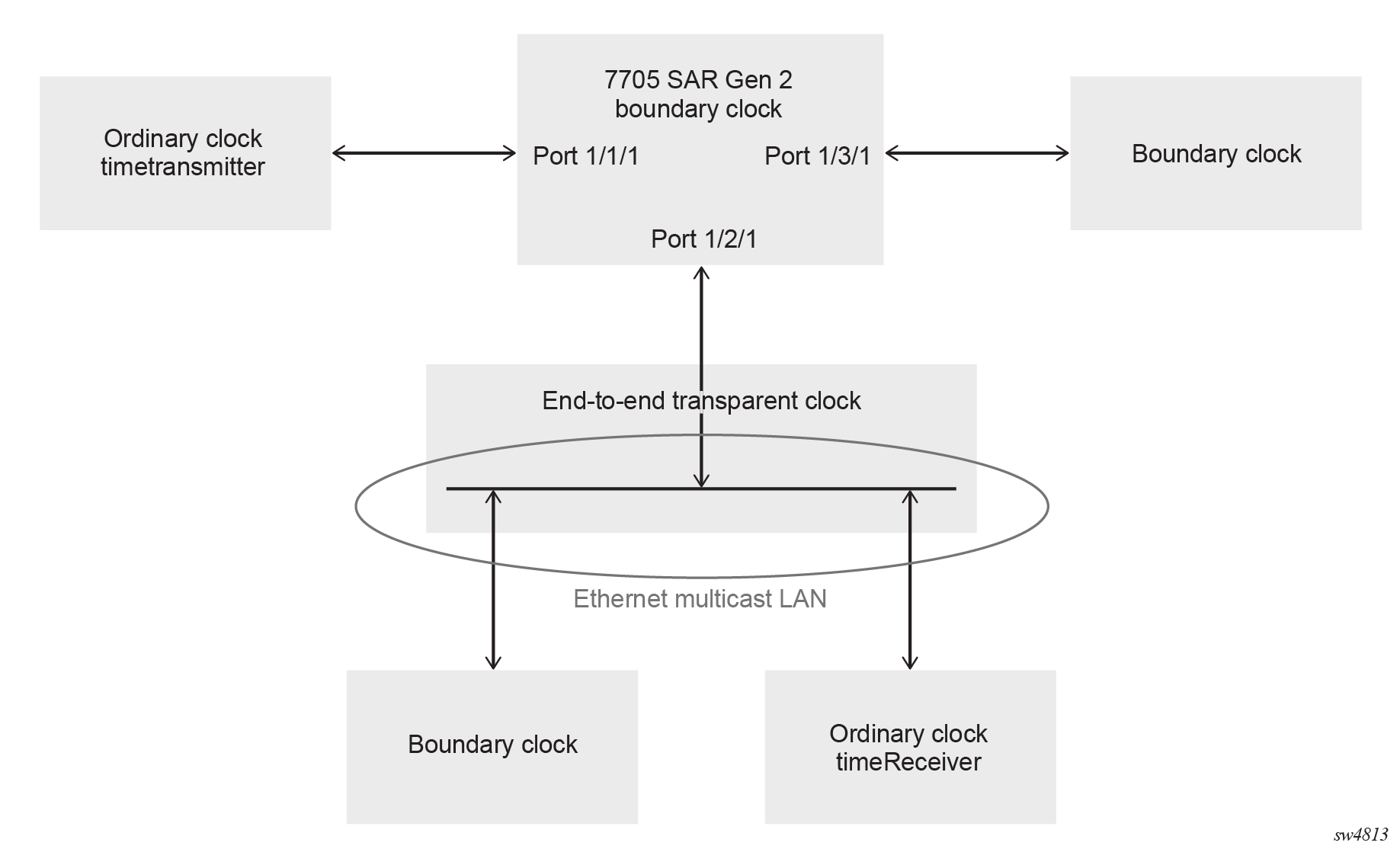
The ordinary clock timeTransmitter, ordinary clock timeReceiver, and boundary clock allow PTP operation over both unicast IPv4/IPv6 and multicast Ethernet at the same time.
The IEEE 1588v2 standard includes the concept of PTP profiles. These profiles are defined by industry groups or standards bodies that define how IEEE 1588v2 should be used for a specific application.
The following profiles are supported on the 7705 SAR Gen 2:
-
IEEE 1588v2 (ieee1588-2008)
-
G.8265.1 (g8265dot1-2010)
-
G.8275.1 (g8275dot1-2014)
-
IEC 61850-9-3 (iec-61850-9-3-2016)
-
C37.238 (c37dot238-2017)
-
G.8275.2 (g8275dot2-2016)
When an ordinary clock timeReceiver or a boundary clock receives Announce messages from one or more configured peers or multicast neighbors, it executes a Best TimeTransmitter Clock Algorithm (BTCA) to determine the state of communication between itself and the peers. The system uses the BTCA to create a hierarchical topology allowing the flow of synchronization information from the best source (the grandmaster clock) out through the network to all boundary and timeReceiver clocks. Each profile has a dedicated BTCA.
If the profile setting for the clock is ieee1588-2008, iec-61850-9-3-2016, or c37dot238-2017, the precedence order for the BTCA is as follows:
-
priority1
-
clockClass
-
clockAccuracy
-
PTP variance (offsetScaledLogVariance)
-
priority2
-
clockIdentity
-
stepsRemoved from the grandmaster
The ordinary clock timeTransmitter, ordinary clock timeReceiver, and boundary clock set their local parameters as listed in the following table.
| Parameter | Value |
|---|---|
|
clockIdentity |
Chassis MAC address following the guidelines of 7.5.2.2.2 of IEEE 1588 |
|
clockClass |
6 — local clock is configured using a time reference from a GNSS receiver 7 — local clock is in holdover after losing time reference from the local GNSS receiver for no more than ten minutes 13 — local clock configured as ordinary clock timeTransmitter and is locked to an external reference 14 — local clock configured as ordinary clock timeTransmitter and in holdover after having been locked to an external source 248 — local clock configured as ordinary clock timeTransmitter and is in free run or the router is configured as a boundary clock 255 — local clock configured as ordinary clock timeReceiver |
|
clockAccuracy |
FE — unknown 21 — when using a time reference from a GNSS receiver |
|
offsetScaledLogVariance |
FFFF — not computed |
If the profile setting for the clock is g8265dot1-2010, the precedence order for the best timeTransmitter selection algorithm is:
-
clockClass
-
priority
The ordinary clock timeTransmitter, ordinary clock timeReceiver, and boundary clock use local settings as listed in the following table.
| Parameter | Value |
|---|---|
|
clockClass |
80-110 — value corresponding to the QL out of the central clock as per Table 1/G.8265.1 255 — the clock is configured as ordinary clock timeReceiver |
|
domain number |
0 to 255 — configured domain value must be within this range when the G.8265.1 profile is used, and is 4 by default |
The g8265dot1-2010 profile is for use in an environment with only ordinary clock timeTransmitters and timeReceivers for frequency distribution.
If the profile setting for the clock is g8275dot1-2014, the precedence order for the best timeTransmitter selection algorithm is very similar to that used with the default profile. It ignores priority1, includes a localPriority, and includes the ability to force a port to never enter timeReceiver state (timeTransmitter-only).
The precedence is as follows:
-
clockClass
-
clockAccuracy
-
PTP variance (offsetScaledLogVariance)
-
priority2
-
localPriority
-
clockIdentity (See Note)
-
stepsRemoved from the grandmaster
This step is typically skipped when comparing two clocks with advertised clock class of less than 128, which is the case for most grandmaster clocks.
The ordinary clock timeTransmitter, ordinary clock timeReceiver, and boundary clock use local settings listed in the following table.
| Parameter | Value |
|---|---|
|
clockIdentity |
Chassis MAC address following the guidelines of 7.5.2.2.2 of IEEE 1588 |
|
clockClass |
165 — local clock configured to a boundary clock and the boundary clock was previously locked to a grandmaster with a clock class of 6 248 — local clock configured as boundary clock 255 — local clock configured as ordinary clock timeReceiver |
|
clockAccuracy |
FE — unknown |
|
offsetScaledLogVariance |
FFFF — not computed |
If the profile setting for the clock is g8275dot2-2016, the precedence order for the best master selection algorithm is very similar to that used with the g8275dot1-2014 profile. It ignores the priority1 parameter, includes a localPriority parameter, and includes the ability to force a port to never enter slave state (master-only). The precedence is as follows:
-
clockClass
-
clockAccuracy
-
PTP variance (offsetScaledLogVariance)
-
priority2
-
localPriority
-
clockIdentity
-
stepsRemoved from the grandmaster
The following table describes the local parameter settings when the profile setting for the clock is g8275dot2-2016.
|
Parameter |
Value and Description |
|---|---|
|
clockIdentity |
Chassis MAC address following the guidelines of 7.5.2.2.2 of IEEE 1588 |
|
clockClass |
6 — local clock is using a time reference from a GNSS receiver 165 — local clock is configured as a boundary clock in holdover; the boundary clock was previously locked to a grandmaster clock with a clock class of 6 248 — local clock is configured as a grandmaster clock or boundary clock in free-run mode 255 — local clock is configured as an ordinary clock slave |
|
clockAccuracy |
0xFE — unknown 0x21 — when using a time reference from a GNSS receiver |
|
offsetScaledLogVariance |
0xFFFF — not computed 0x4e5d (1.8E-15) — when using a time reference from a GNSS receiver |
There is a limit on the number of external PTP clocks to which the ordinary clock timeReceiver or boundary clock requests unicast service (number of configured peers). There is also a limit to the number of external PTP clocks to which the ordinary clock timeTransmitter or boundary clock grants unicast service (number of discovered peers). An association where the boundary clock has a symmetric relationship with another boundary clock (in other words, they both have the other as a configured peer) consumes a request and a grant unicast service in each router.
The number of configured Ethernet ports is not restricted.
There are limits to the maximum transmitted and received event message rates supported in the router. Each unicast IP service established consumes a portion of one of the unicast message limits. When either limit is reached, the device sends a grant response with zero in the duration field to refuse additional unicast service requests.
See the scaling guide for the appropriate release for the specific unicast message limits related to PTP.
Multicast messages are not considered when validating the unicast message limit. When multicast messaging on Ethernet ports is enabled, the PTP load must be monitored to ensure usage capabilities are not exceeded. If the capacity usage reaches 100%, the PTP software process on the router is at its limit of transmitting and receiving PTP packets.
Several commands are available for use to monitor PTP load:
-
Use the following command to identify the load of the PTP software process.
show system cpu -
Use the following command to display aggregate packet rates.
show system ptp statistics
Because the volume of PTP messages received over the Ethernet ports is unpredictable, use the statistics commands to identify the source of the message load..
Use the following commands to display received packet rates.
show system ptp port
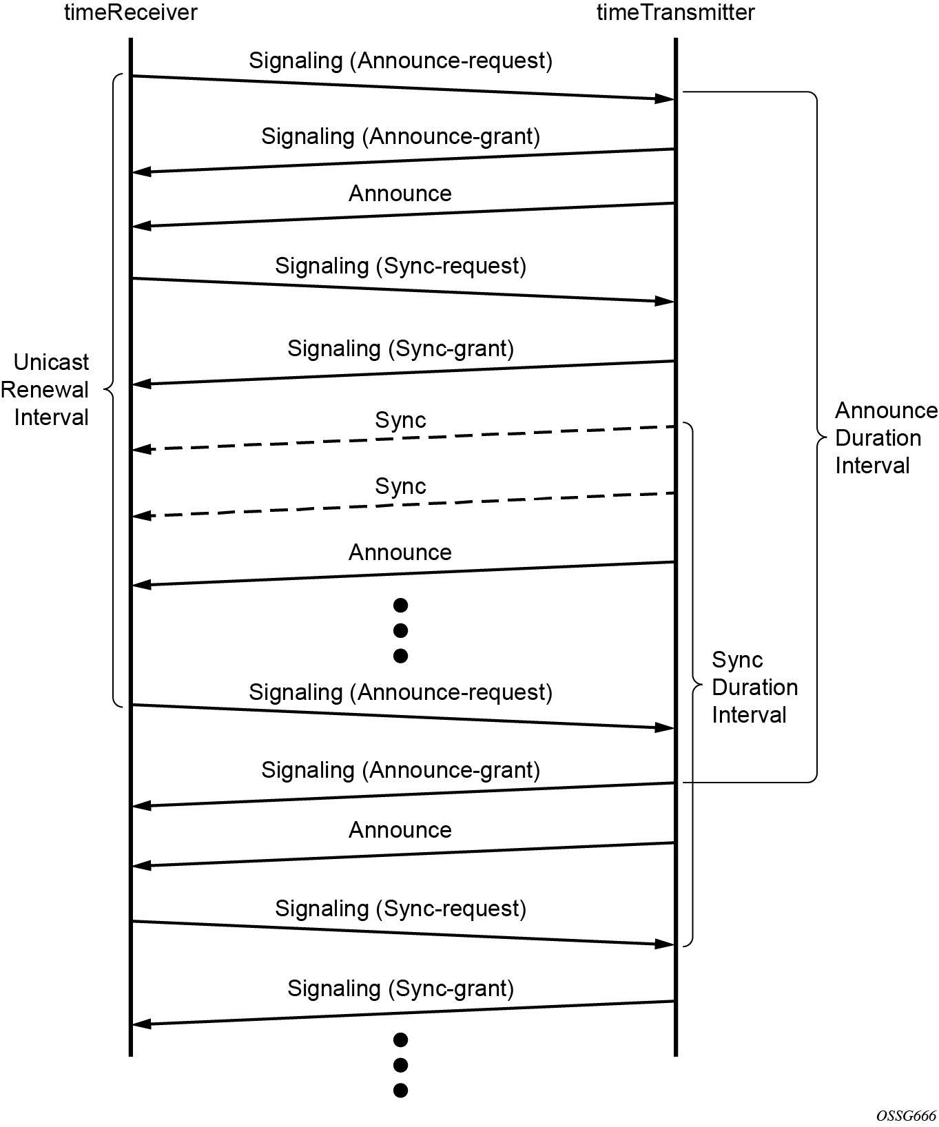
show system ptp port detailMessaging sequence between the PTP timeReceiver clock and PTP timeTransmitter clock shows the unicast negotiation procedure performed between a timeReceiver and a peer clock that is selected to be the timeTransmitter clock. The timeReceiver clock requests Announce messages from all peer clocks but only request Sync and Delay_Resp messages from the clock selected to be the timeTransmitter clock.
PTP clock synchronization
The IEEE 1588v2 standard synchronizes the frequency and time from a timeTransmitter clock to one or more timeReceiver clocks over a packet stream. This packet-based synchronization standard defines transport to use UDP/IP with unicast or Ethernet with multicast.
As part of the basic synchronization timing computation, a number of event messages are defined for synchronization messaging between the PTP timeReceiver port and PTP timeTransmitter port. A one-step or two-step synchronization operation can be used, with the two-step operation requiring a follow-up message after each synchronization message. Ordinary clock timeTransmitter and boundary clock timeTransmitter ports use one-step operation; ordinary clock timeReceiver and boundary clock timeReceiver ports can accept messages from either one-step or two-step operation timeTransmitter ports.
The IEEE 1588v2 standard includes a mechanism to control the topology for synchronization distribution. The Best TimeTransmitter Clock Algorithm (BTCA) defines the states for the PTP ports on a clock. One port is set into timeReceiver state and the other ports are set to timeTransmitter (or passive) states. Ports in timeReceiver state recovered synchronization delivered by from an external PTP clock and ports in timeTransmitter state transmit synchronization to toward external PTP clocks.
The following figure shows the basic synchronization timing computation between the PTP timeReceiver clock and PTP best timeTransmitter. This figure illustrates the offset of the timeReceiver clock referenced to the best timeTransmitter signal during startup.
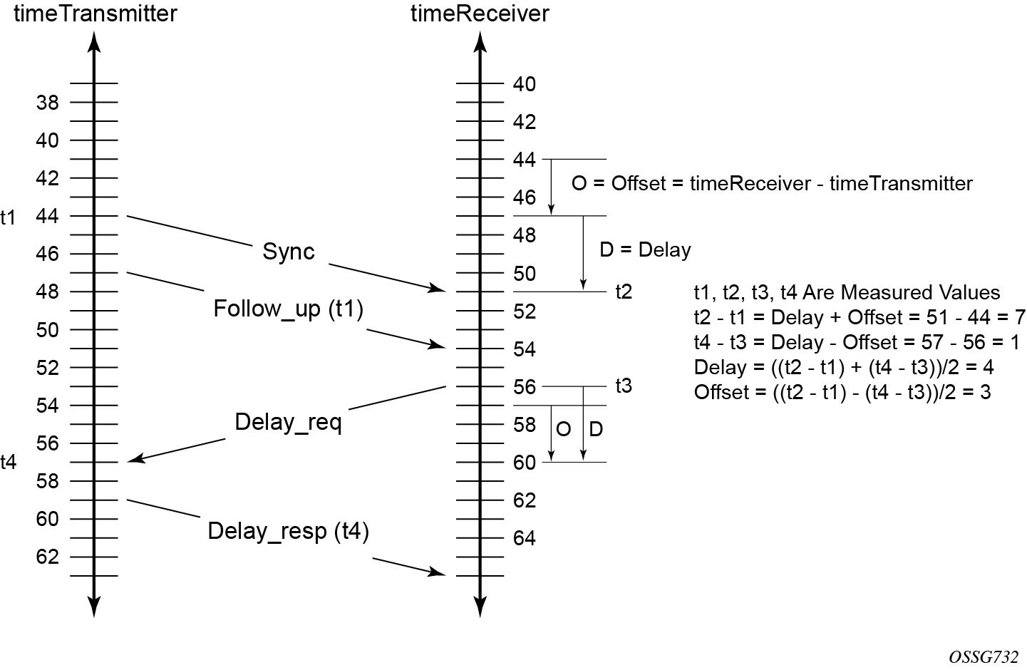
When using IEEE 1588v2 for distribution of a frequency reference, the timeReceiver calculates a message delay from the timeTransmitter to the timeReceiver based on the timestamps exchanged. A sequence of these calculated delays contain information of the relative frequencies of the timeTransmitter clock and timeReceiver clock but has a noise component related to the PDV experienced across the network. The timeReceiver must filter the PDV effects to extract the relative frequency data, then adjust the timeReceiver frequency to align with the timeTransmitter frequency.
When using IEEE 1588v2 for distribution of time, the 7705 SAR-Hx and 7705 SAR-Mx use the four timestamps exchanged using the IEEE 1588v2 messages to determine the offset between the router time base and the external timeTransmitter clock time base. The router determines the offset adjustment and then in between these adjustments, the router maintains the progression of time using the frequency from the central clock of the router. This allows time to be maintained using a SyncE input source even if the IEEE 1588v2 communications fail. When using IEEE 1588v2 for time distribution, the central clock should at a minimum have a system timing input reference enabled.
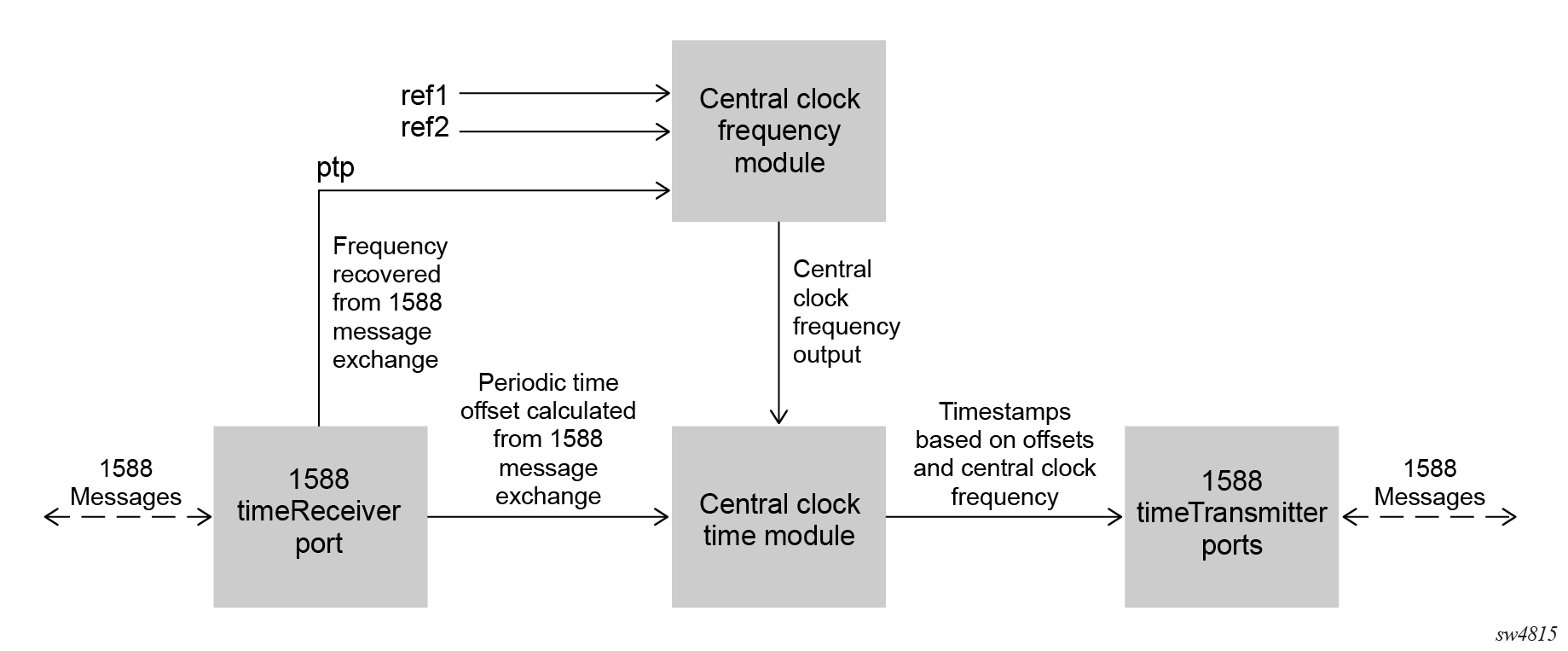
The following figure shows a logical model for using PTP/1588 for network synchronization.
Synchronization uncertainty
The PTP protocol uses the BTCA to build the network topology from a PTP grandmaster, through one or more boundary clocks, and into timeReceiver clocks. This mechanism relies on the grandmaster information contained in the Announce messages sent between these clocks. While the BTCA is designed to create the topology quickly and without any timing loops, it does not account for the time it takes for each clock to synchronize its local time with that of its newly selected parent clock.
To address this, the IEEE and ITU-T adds the synchronizationUncertain bit to the header of Announce message. A grandmaster or boundary clock sets this bit to true when it is calibrating. In addition, if this bit is set to true in the Announce messages from its parent clock, the boundary clock always transmits this bit as true. This allows the topology to settle quickly, but also provides an indication to the final timeReceiver clocks as to when they can trust the time being delivered by the network.
The optional synchronizationUncertain bit (flagField octet 1, bit 6) defined in the G.8275.1, G.8275.2, and IEEE 1588 specifications in Announce messages indicates the synchronization uncertainty of the PTP clock to the user and downstream clocks. A synchronizationUncertain bit value of 1 indicates a SyncUncertain TRUE state, meaning the local clock is still in the transient phase and attempting to achieve stability. A synchronizationUncertain bit value of 0 indicates a SyncUncertain FALSE state, meaning the local clock has reached the steady state phase.
Transition to the SyncUncertain FALSE state occurs when all of the following conditions are true for a number of consecutive, stable PTP time update windows:
- the parent PTP clock is in a SyncUncertain FALSE state
- PTP time recovery is locked
- the grandmaster PTP clock is Clock Class 6 or 7
- the central frequency clock is locked, and the QL of the frequency is QL-PRC/QL-PRS
- PTP frequency recovery is locked if PTP is used for frequency and the profile is G.8275.2 or IEEE 1588v2
The transition back to the SyncUncertain TRUE state occurs if any of the preceding conditions are not met, even momentarily, and the stable PTP time update window count resets to 0.
- MD-CLI
configure system ptp tx-while-sync-uncertain false - classic
CLI
configure system ptp no tx-while-sync-uncertain
Performance considerations
Although IEEE 1588v2 can be used on a network that is not PTP-aware, the use of PTP-aware network elements (boundary clocks) within the packet-switched network improves synchronization performance by reducing the impact of PDV between the grandmaster clock and the timeReceiver clock. When IEEE 1588v2 is used to distribute high-accuracy time, such as for mobile base station phase requirements, the network architecture requires the deployment of PTP awareness in every device between the grandmaster clock and the mobile base station timeReceiver.
In addition, performance is also improved by the removal of any PDV caused by internal queuing within the boundary clock or timeReceiver clock. This is accomplished with hardware that is capable of detecting and time stamping the IEEE 1588v2 packets at the Ethernet interface. This capability is referred to as port-based timestamping.
Port-based timestamping of PTP messages
To meet the stringent performance requirements of PTP mobile network applications, the 1588 packets must be timestamped at the ingress and egress ports. This requires the use of 1588 port-based timestamping on the ports handling the PTP messages. This avoids any possible PDV that may be introduced between the port and the CPM. The ability to timestamp in the interface hardware is provided on a subset of the MDA assemblies of the routers.
When configuring the ptp-hw-assist command for PTP over IP, a loopback address must be used for PTP to ensure these message are timestamped at the port, even after the routing topology changes. To configure the loopback address, use one of the following commands:
-
MD-CLI
configure system security source-address ipv4 ptp address configure system security source-address ipv6 ptp address -
classic CLI
configure system security source-address application ptp
configure system security source-address application6 ptp
Enabling the ptp-hw-assist command option within a Layer 3 interface is only supported if one of the following conditions is met:
-
all physical ports contained in the interface support PBT for PTP over UDP/IPv4
-
all physical ports contained in the interface support PBT for PTP over UDP/IPv6 and a loopback IPv6 address is configured for PTP using the following commands:
-
MD-CLI
configure system security source-address ipv6 ptp address address configure service vprn source-address ipv6 ptp address address -
classic CLI
configure system security source-address application6 ptp ip-int-name | ip-address
configure service vprn source-address application6 ptp ip-int-name | ip-address
-
While the ptp-hw-assist feature supports port timestamping for a single router interface per physical port, the ptp-timestamping port-level configuration feature supports port timestamping for multiple router interfaces per physical port. The ptp-timestamping feature applies port timestamping to PTP messages using UDP/IPv4 or UDP/IPv6 transport. The destination IP addresses specified under the port-level ptp-timestamping feature should be configured as one of the source addresses defined for PTP use.
The ptp-timestamping feature enables the local PTP clock to use PTP over IP over multiple router interfaces per physical port. This feature can also be used for router interfaces across different router instances that have the same local PTP IP address.
When using the ptp-timestamping feature, all received messages that match the characteristics (PTP protocol, UDP over IP with the configured address, PTP event message) must be delivered to the PTP process of the node.
PTP capabilities
To exchange PTP messages between the router and an external 1588 clock, a unicast session must be established for each PTP message type using the unicast negotiation procedures. The router allows the configuration of the message rate to be requested from external 1588 clocks. The router also supports a range of message rates that it grants to requests received from the external 1588 clocks. The IEEE 1588 standard allows the grantor port to respond with a shorter duration than what was in the request. The router can accept such a grant and uses that duration. The router issues a renegotiation before the duration expires.
The following table describes the ranges for both the rates that the 7705 SAR-Hx, and 7705 SAR-Mx can request and grant.
| Message type | Rates requested | Rates granted | ||
|---|---|---|---|---|
| Minimum | Maximum | Minimum | Maximum | |
Announce |
1 packet every 16 seconds |
8 packets per second |
1 packet every 16 seconds |
8 packets per second |
Sync |
1 packet per second |
64 packet per second |
1 packet per second |
128 packet per second |
Delay_Resp |
1 packet per second |
64 packets per second |
1 packet per second |
128 packets per second |
(Duration) |
300 |
300 |
1 |
1000 |
State and statistics data for each PTP peer are available to assist in detecting failures or unusual situations.
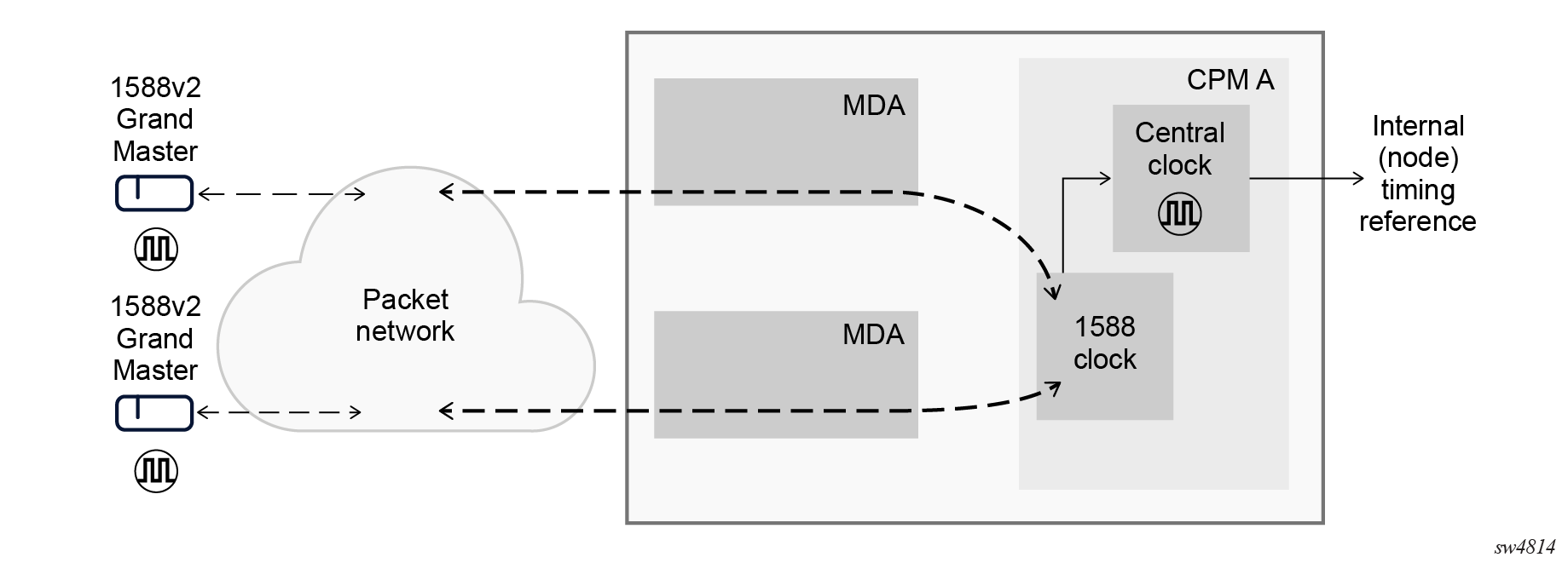
PTP ordinary timeReceiver clock for frequency
Traditionally, only clock frequency is required to ensure smooth transmission in a synchronous network. The PTP ordinary clock with timeReceiver capability on the router provides another option to reference a Stratum-1 traceable clock across a packet-switched network. The recovered clock can be referenced by the internal SSU and distributed to all slots and ports.
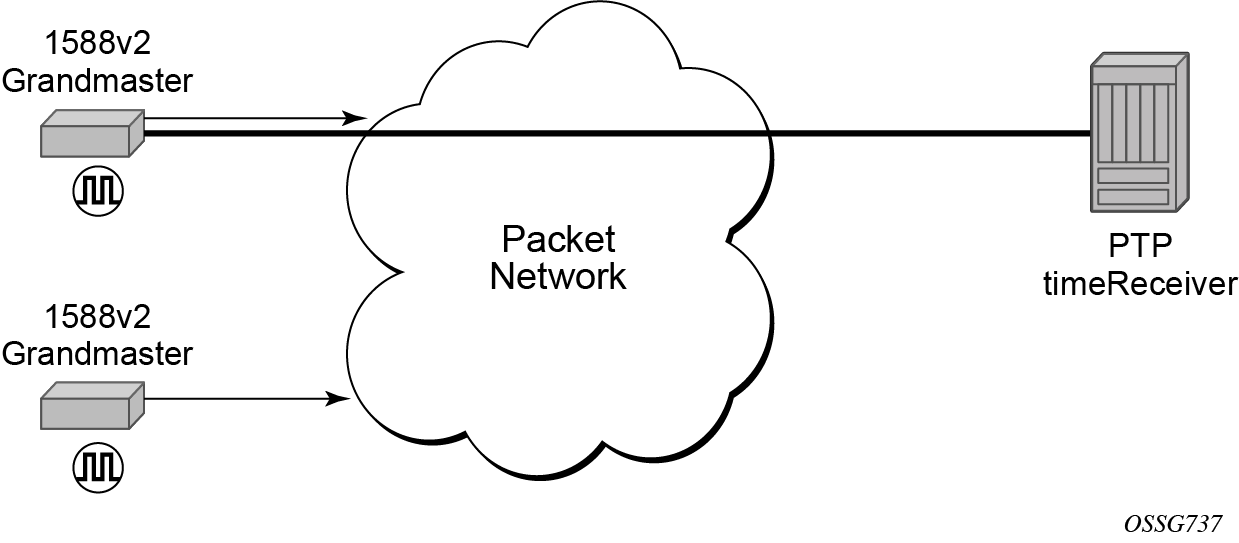
The following figure shows a PTP ordinary timeReceiver clock network configuration.
The PTP timeReceiver capability is implemented on the CPM, version 3 or later. The IEEE 1588v2 messages can ingress and egress the router on any line interface. The following figure shows the operation of an ordinary PTP clock in timeReceiver mode.
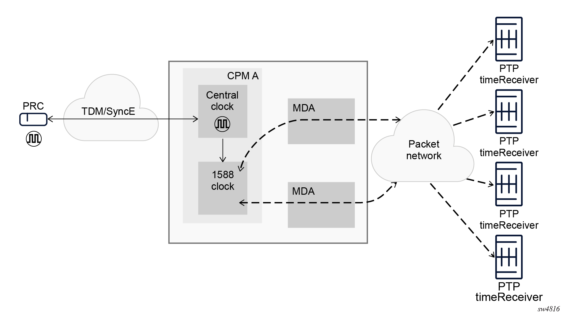
PTP ordinary timeTransmitter clock for frequency
The router supports the PTP ordinary clock in timeTransmitter mode. Normally, an IEEE 1588v2 grandmaster is used to support many timeReceivers and boundary clocks in the network. In cases where only a small number of timeReceivers and boundary clocks exist and only frequency is required, a PTP integrated timeTransmitter clock can greatly reduce hardware and management costs to implement PTP across the network. It also provides an opportunity to achieve better performance by placing a timeTransmitter clock closer to the edge of the network, as close to the timeReceiver clocks as possible. The following figure shows a PTP timeTransmitter clock network configuration.
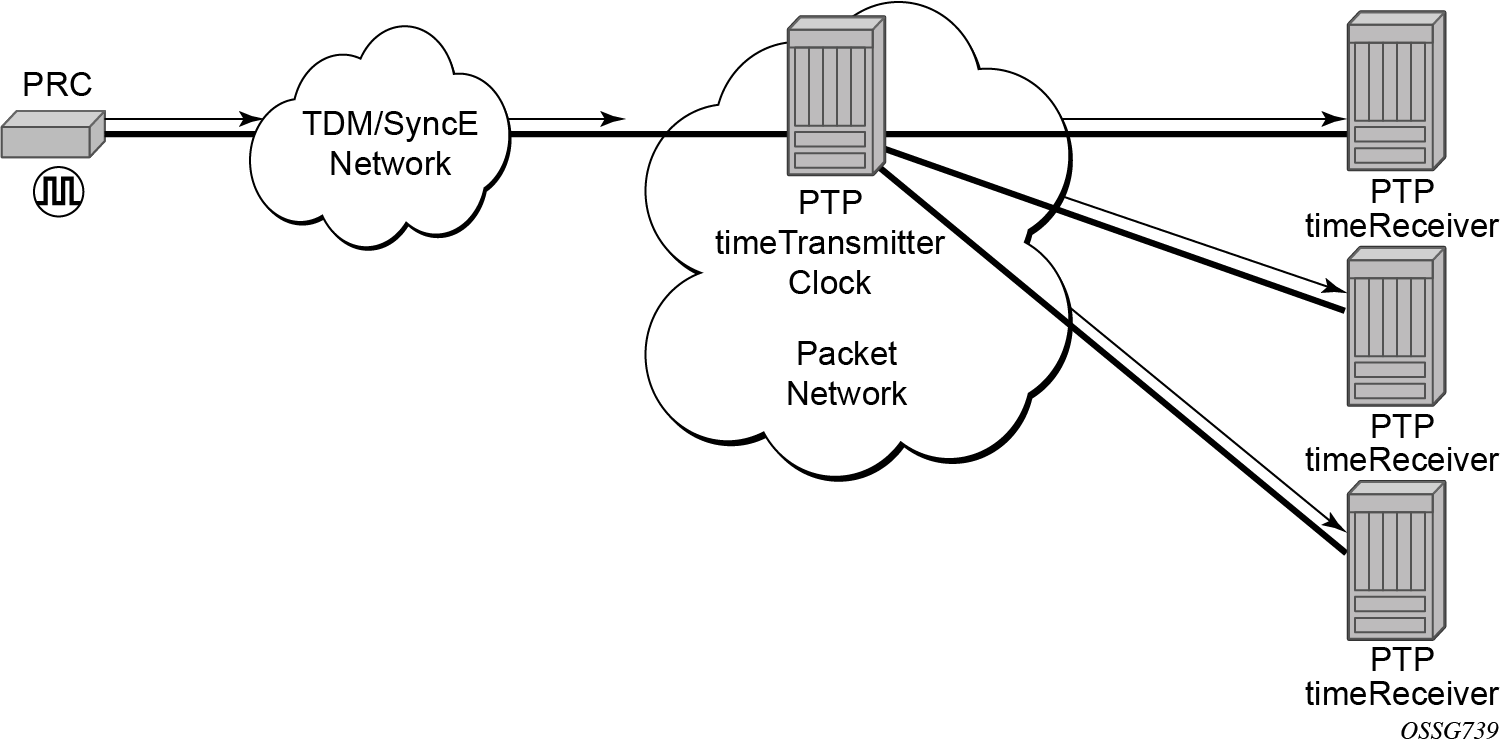
All packets are routed to their destination via the best route as determined in the route table, as shown in the following figure. It does not matter which ports are used to ingress and egress these packets (unless port based time stamping is enabled for higher performance).
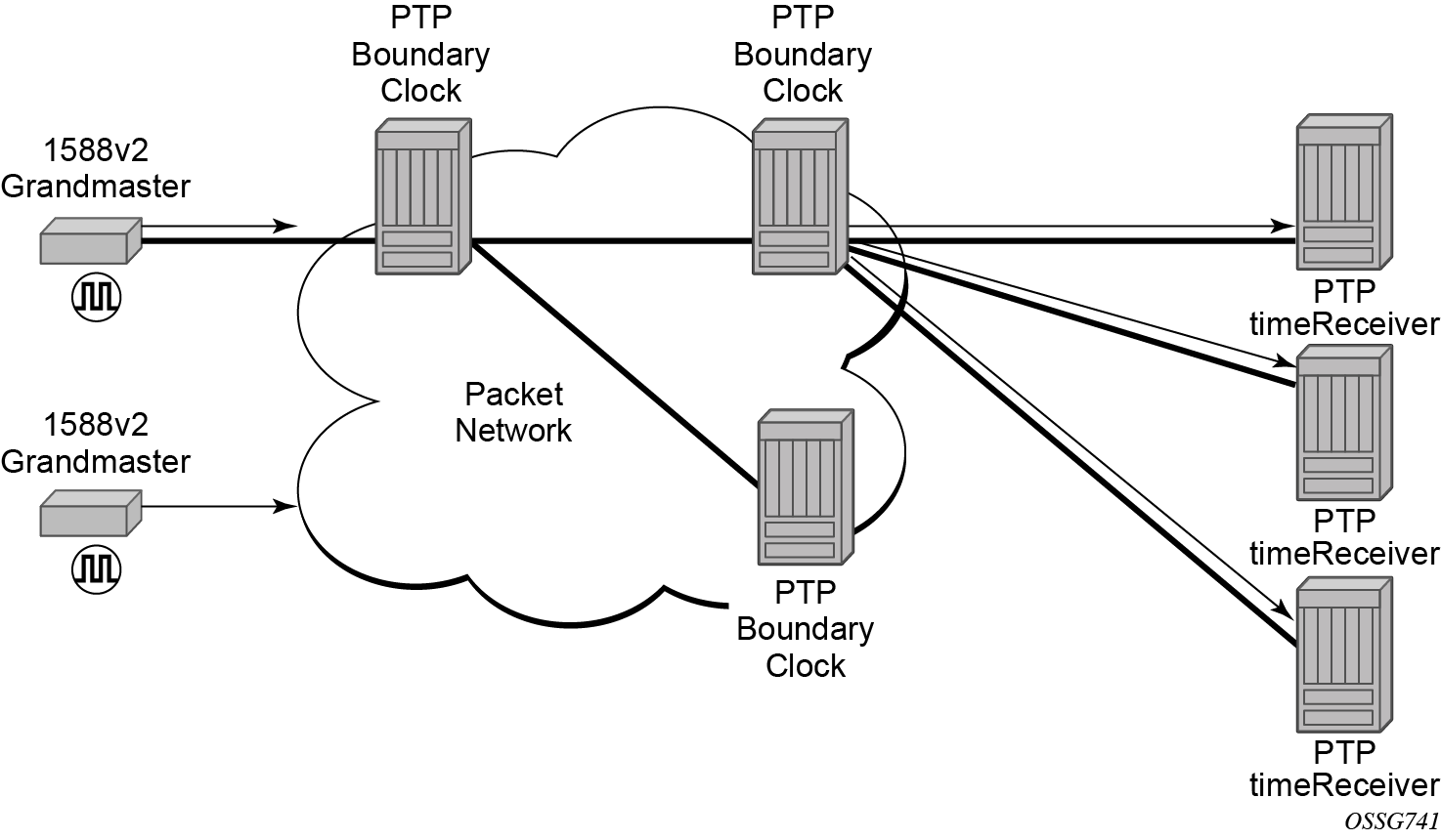
PTP boundary clock for frequency and time
The router supports boundary clock PTP devices in both timeTransmitter and timeReceiver states.
IEEE 1588v2 can function across a packet network that is not PTP-aware. However, the performance may be unsatisfactory and unpredictable. PDV across the packet network varies with the number of hops, link speeds, utilization rates, and the inherent behavior of the routers. By using routers with boundary clock functionality in the path between the grandmaster clock and the timeReceiver clock, one long path over many hops is split into multiple shorter segments, allowing better PDV control and improved timeReceiver performance. This allows PTP to function as a valid timing option in more network deployments, allowing better scalability and increased robustness in specific topologies, such as rings.
Boundary clocks can simultaneously function as a PTP timeReceiver of an upstream grandmaster (ordinary clock) or boundary clock, and as a PTP timeTransmitter of downstream timeReceivers (ordinary clock) and boundary clocks, as shown in the following figure.
Nokia strongly recommends using port-based timestamping in every network element between the grandmaster and the end timeReceiver application to achieve time accuracies of one microsecond required by mobile applications.
The router always uses the frequency output of the central frequency clock to maintain the timebase within the router. When using the G.8275.1 profile, it is mandatory to have the central frequency clock configured to use a Layer 1 frequency source, such as a SyncE port. For other profiles, Nokia recommends using a Layer 1 frequency source. If a Layer 1 frequency source is unavailable, enable PTP as a source for the central frequency clock to have frequency for timestamping traceable to a high accuracy source.
When a router with an enabled GNSS port is configured with boundary clock functionality, the boundary clock acts as a grandmaster clock. The timeReceiver function stops and the timeTransmitter ports use frequency and time recovered from the GNSS port.
PTP timeTransmitter clock for frequency and time distribution
PTP timeTransmitter clock capability for frequency and time distribution is implemented on the7705 SAR-Hx and 7705 SAR-Mx.
GNSS must be the active system timing and frequency reference for routers that are used as a grandmaster clock. The PTP timeTransmitter clock can be used for frequency and time distribution. See Configuring system timing to use a GNSS RF port for information about configuring the router to use GNSS as a system timing reference.
Use the following commands to configure the router as a grandmaster clock:
- MD-CLI
configure system ptp profile ieee1588-2008 configure system ptp clock-type master-only configure system ptp admin-state enable - classic
CLI
configure system ptp profile ieee1588-2008
configure system ptp clock-type ordinary master
configure system ptp no shutdown
ITU-T G.8275.2 profile and APTS
The 7705 SAR-Hx and 7705 SAR-Mx support Recommendation ITU-T G.8275.2, which, similar to Recommendation ITU-T G.8275.1, specifies the architecture that allows the distribution of time and phasing. Recommendation ITU-T G.8275.1 supports full-timing from the network and Recommendation ITU-T G.8275.2 supports partial-timing (PTS) and APTS.
When the router is configured to use the G.8275.1 or G.8275.2 profile, it uses an alternate BTCA for best timeTransmitter clock selection. This BTCA includes a PTP dataset comparison that is defined in IEEE 1588-2008, but with the following differences:
- the priority1 value is removed from the dataset comparison
- the master-only value must be considered
- multiple active grandmaster clocks are allowed; therefore, the BTCA selects the nearest clock of equal quality
- a port-level local-priority attribute value is used to select a timeReceiver port if two ports receive an Announce message. This attribute is used as a tiebreaker in the dataset comparison algorithm if all other previous attributes of the datasets being compared are equal.
- the local-priority value is considered for the default dataset
When the clock is configured as a boundary clock, the GNSS is treated as a virtual PTP port into the BTCA. On systems with redundant GNSS, the preference in the BTCA shall be the local GNSS followed by the standby GNSS. The GNSS receiver shall only be considered into the BTCA if it is in locked state. Also in these systems, when one of the GNSS is selected as the parent clock, there may still be a PTP port running frequency and time recovery from a remote PTP timeTransmitter port as a backup. The ptp statistics reflect this backup session.
When the PTP clock is configured to use the G.8275.2 profile without GNSS configured, the clock operates using PTS. When the PTP clock is configured to use the G.8275.2 profile and the internal GNSS is configured and operationally up, GNSS is the preferred reference by default and is selected as the source of time for PTP. For extra resilience, APTS can be deployed by configuring a PTP backup over a network with PTP support to a remote grandmaster clock.
When the clock is configured as a boundary clock, the GNSS is treated as a virtual PTP port into the BTCA. On systems with redundant GNSS, the preference in the BTCA is the local GNSS followed by the standby GNSS. The GNSS receiver is considered into the BTCA when it is in locked state. Also in these systems, when one of the GNSS is selected as the parent clock, there may still be a PTP port running frequency and time recovery from a remote PTP timeTransmitter port as a backup. The PTP statistics reflect this backup session.
During normal operation, the local GNSS source is the reference for time and frequency. If the GNSS source fails, the PTP backup is automatically used to keep the clocks synchronized and stable. The delay offset value, which is calculated while the GNSS source was up, is applied to the PTP backup to keep time and phase as accurate as possible. See GNSS failure with APTS for more information about APTS functionality during a GNSS failure.
The following table describes the mapping between ITU-T G.8275.2 and PTP clock types. T-BC-A and T-TSC-A clocks are applicable to APTS.
| Clock type from ITU-T G.8275.2 | Description | Clock type from IEEE 1588 |
|---|---|---|
|
T-GM |
timeTransmitter ordinary clock (clock with a single PTP port; cannot be a timeReceiver from another PTP clock) |
Ordinary clock |
|
timeTransmitter boundary clock (clock with multiple PTP ports; cannot be a timeReceiver from another PTP clock) |
Boundary clock1 |
|
|
T-BC-P (partial) |
Boundary clock (may become a grandmaster clock, or may be a timeReceiver from another PTP clock) |
Boundary clock |
|
T-BC-A (assisted partial) |
Boundary clock assisted by a local time reference that is used as a primary source of time (may become a grandmaster clock, or may be a timeReceiver to another PTP clock) |
Boundary clock2 |
|
T-TSC-P (partial) |
Always timeReceiver; single-port ordinary clock |
Ordinary clock |
|
PTP clock at the end of the PTP synchronization chain; multiple port clock |
Boundary clock1 |
|
|
T-TSC-A (assisted partial) |
Always timeReceiver; single-port ordinary clock assisted by a local time reference that is used as a primary source of time |
Ordinary clock2 |
|
PTP clock at the end of the PTP synchronization chain; multiple-port clock assisted by a local time reference that is used as a primary source of time |
PTP message encapsulations
For physical ports located on an MDA on the 7705 SAR-Hx and 7705 SAR-Mx, PTP messages are supported in the following encapsulations:
- PTP within raw Ethernet (no VLAN header)
- PTP within UDP/IPv4 or UDP/IPv6 within raw Ethernet (no VLAN header)
No other encapsulations are supported.
PTP time for system time and OAM time
PTP has the potential to provide much more accurate time into the router than can be obtained with NTP. This PTP recovered time can be made available for system time and OAM packet timestamping to improve the accuracy of logged events and OAM delay measurements. To activate PTP as the source for these internal time bases, allocate PTP as a local server into NTP. This allows the NTP time recovery to use PTP as a time source and then distribute it to system time and the OAM process within the router. This activation also affects the operation of the NTP server within the SR OS. The PTP server appears as an NTP stratum 0 server. Consequently the SR OS advertises itself as an NTP Stratum 1 server to external peers and clients. This activation may impact the NTP topology.
PTP within routing instances
PTP is supported over direct Ethernet encapsulation (that is, PTP ports) and UDP/IP encapsulation (that is, PTP peers). PTP ports operate below the routing plane. They can be used on appropriate ports irrespective of any type of router interface also on the port. PTP peers operate at the routing plane and have restrictions based on and across the following router instances.
Transmission and reception of PTP messages using PTP peers is supported in the following contexts:
-
Network interface in the Base routing instance (configure router interface)
-
IES interface (configure service ies interface)
-
VPRN interface (configure service vprn interface)
Transmission and reception of PTP messages using PTP peers is not supported in the following contexts:
-
IES spoke SDP interface (configure service ies spoke-sdp interface)
-
VPRN spoke SDP interface (configure service vprn spoke-sdp interface)
-
VPRN transport tunnel (configure service vprn auto-bind-tunnel or configure service vprn spoke-sdp)
-
Any interface of the management router instance
-
Any interface of the vpls-management router instance
-
Any interface of a user created CPM router instance
It is important to note that there is only one PTP clock within the router. All PTP ports and PTP peers communicate into one clock instance. Only one router instance may have PTP peers configured, which means that only that router instance (or PTP port) can run the timeReceiver functionality and recover time from an external PTP clock. All other router instances only support the dynamic PTP peers. The PTP process in the router only includes outward server time toward the dynamic PTP peers. The dynamic PTP peers are shared across all router instances. If controlling the number of dynamic peers that can be consumed by a routing instance is required, the user must configure it specifically for that routing instance.
PTSF-unusable for G.8275.1
The PTP clock in the router monitors the Sync, Follow_Up (if present), and Delay_Resp messages received from external neighbor ports. If a high variation is detected in the network path between the external neighbor port and the local port, that neighbor port is considered unusable (PTSF-unusable as defined in the ITU-T G.8275.1 recommendation). When a neighbor is unusable, all Announce messages from that neighbor are discarded on reception and excluded from the BTCA. If the neighbor is the parent clock to the local clock, the local clock must either select a new parent clock or go into holdover. In addition, any neighbor clock marked as unusable cannot act as the parent to the local PTP clock until the underlying condition is investigated and resolved, and the unusable state is cleared. The unusable state is cleared when PTP, PTSF-unusable monitoring, or the local PTP port is administratively disabled; when the PTP port is deleted; or when the external neighbor port stops sending messages to the node. The user can also clear the state by using the following command.
clear system ptp port neighbor ptsf-unusableProfile interworking
There is one PTP clock within an SR OS system. The clock runs a BTCA and can set a port into timeReceiver state to recover frequency, time, or both. The recovery process is controlled by the rules of a primary profile. The SR OS also allows frequency, time, or both to be distributed outward from the clock using PTP messages that conform to the rules of an alternate profile. The primary profile and alternate profiles include a command option to configure the standard profile that defines these rules. The following guidelines apply to profile interworking on the 7705 SAR-Hx and 7705 SAR-Mx:
- Alternate profiles can only be configured if the primary profile is using standard profile g8275dot1-2014 or g8275dot2-2016.
- Alternate profiles can use standard profiles g8265dot1-2010, ieee1588-2008, g8275dot1-2014, g8275dot2-2016, iec-61850-9-3-2016, or c37dot238-2017.
- The primary profile and an alternate profile can use the same standard profile.
- Multiple alternate profiles can also use the same standard profile.
Alternate profiles are associated with PTP ports and peers. Alternate profile associations are configured for PTP ports and learned by PTP peers. PTP peer alternate profiles are learned by matching the domain number of received unicast messaging with the domain of the configured alternate profile. Configured peers always use the primary profile.
Additionally, if the log-delay-interval and log-sync-interval commands are not changed from their default values, the values change if the primary profile changes. This behavior may result in an unexpected message rate if the default values are retained.
The following table lists the profile interworking between the primary and alternate profiles depending on the standard profile used as the primary on the 7705 SAR-Hx and 7705 SAR-Mx.
| Standard profile used in primary profile | Standard profile allowed in alternate profile |
|---|---|
|
g8275dot1-2014 |
g8265dot1-2010 ieee1588-2008 g8275dot1-2014 g8275dot2-2016 iec-61850-9-3-2016 c37dot238-2017 |
|
g8275dot2-2016 |
g8265dot1-2010 ieee1588-2008 g8275dot1-2014 g8275dot2-2016 iec-61850-9-3-2016 c37dot238-2017 |
|
g8265dot1-2010 ieee1588-2008 iec-61850-9-3-2016 c37dot238-2017 |
Not allowed |
Annex J performance monitoring statistics
Support is provided for the collection of performance monitoring statistics for the time recovery algorithm based on Annex J/IEEE1588-2019. The following table describes the record index values.
|
Record index value |
Record shown |
|---|---|
|
0 |
current 15-minute interval |
|
1-96 |
15-minute interval within the last 24 hours |
|
97 |
current 24-hour interval |
|
98 |
previous 24-hour interval |
|
501 |
current minute interval |
|
502-516 |
one-minute interval within the last 15 minutes |
Each record includes the average, minimum, maximum, and standard deviation for the following statistics:
- offset-from-master
- mean-path-delay
- timeTransmitter-to-timeReceiverDelay (master-to-slave-delay)
- timeReceiver-to-timeTransmitter delay (slave-to-master-delay)
These performance statistics are available in the following scenarios:
- local active timeReceiver port to remote PTP parent
- local active GNSS to backup PTP port
- local active timeReceiver port to other selected local PTP ports
In the local active timeReceiver port to remote PTP parent scenario, the local active timeReceiver port and the remote parent timeTransmitter port are compared. In a system where the PTP has stabilized, the offset-from-master tends toward 0. A high value indicates that the PTP path has high packet delay variation or high asymmetry.
In the local active GNSS to backup PTP port scenario, when a platform includes a GNSS receiver that is being used as a PTP time source with G.8275.1 or G.8275.2 as the PTP profile, the PTP clock runs a PTP timeReceiver port with an external timeTransmitter port, if one is available. If the PTP clock runs a PTP timeReceiver port, the Annex J statistics are computed as a comparison between the timeReceiver computed time and the GNSS time. Computing the Annex J statistics this way can provide a good indication for PTP performance should the GNSS lose lock and the node switches to use PTP input as its source of time.
In the local active timeReceiver port to other selected local PTP ports scenario, the local active timeReceiver port and another timeReceiver port in the router are compared. Up to four timeReceiver ports can be monitored simultaneously. In this case, these timeReceiver port are designated to be monitored by configuring the PTP port (or PTP peer) to be a monitorReceiver. At the remote end of these monitored PTP ports, the timeTransmitter port can be configured to be monitorSender so that the monitor process can proceed correctly, no matter the PTP state of the port.
PTP path trace
SR OS supports PTP path trace of IEEE1588-2019 clause 16.2. This feature records and displays the chain of PTP clocks from the local clock up to the grandmaster clock.
A node-level configuration option allows the user to include or exclude the PATH_TRACE TLV. If this feature is enabled and the Announce message received from the parent clock does not include the TLV, the SR OS boundary clock creates the TLV with the local clock identity and includes that TLV in the Announce message transmitted by the node.
SR OS supports a maximum length chain of 40 clocks in the PATH_TRACE TLV. If this number is exceeded, SR OS includes only the closest 40 clock identifiers in the transmitted PATH_TRACE TLV.
IP hashing as an LSR
It is now possible to include IP header in the hash routine at an LSR for the purpose of spraying labeled-IPv4 and labeled-IPv6 packets over multiple equal cost paths in ECMP in an LDP LSP and over multiple links of a LAG group in all types of LSPs.
A couple of configurable options are supported. The first option is referred to as the Label-IP Hash option and is designated in the CLI as lbl-ip. When enabled, the hash algorithm parses down the label stack and after it hits the bottom of the stack, it checks the next nibble. If the nibble value is four or six then it assumes it is an IPv4 or IPv6 packet. The result of the hash of the label stack, along with the incoming port and system IP address, is fed into another hash along with source and destination address fields in the IP packet's header. The second option is referred to as IP-only hash and is enabled in CLI using ip-only. It operates the same way as the Label-IP Hash method except the hash is performed exclusively on the source and destination address fields in the IP packet header. This method supports both IPv4 and IPv6 payload.
By default, MPLS packet hashing at an LSR is based on the whole label stack, along with the incoming port and system IP address. This method is referred to as the Label-Only Hash option and is enabled by entering lbl-only.
configure system load-balancing lsr-load-balancingAuto-provisioning
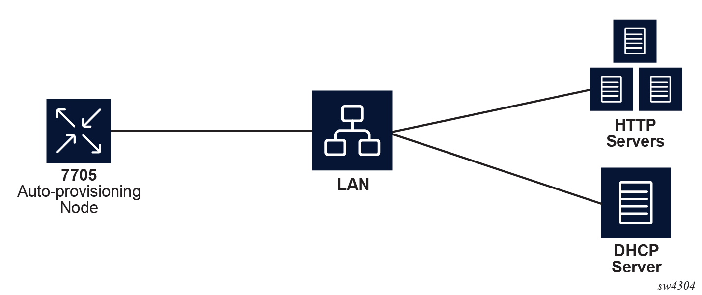
Auto-provisioning is used to provision a node using an external DHCP server and file server. It is used to obtain a configuration file and an image file from an external server using an in-band mechanism. Auto-provisioning is not compatible with an out-of-band management port.
Before using auto-provisioning, the SR OS must be booted up and running the application image. In addition, it needs to have some minimum configuration before the auto-provision script is executed by the operator.
After the auto-provision application is triggered using a tools command, SR OS checks all operationally up ports without IP addresses and send DHCP discovery to these interfaces. The DHCP server needs to be configured with Option 67 and the user must provide the SR OS with the URL of a file server and the corresponding directory for the image.
Example of a network with no DHCP relay to Example of a network with multiple subnets describe scenarios in which auto-provisioning are used.
In Example of a network with no DHCP relay, there is no DHCP relay and all IP addresses are assigned from a single pool.
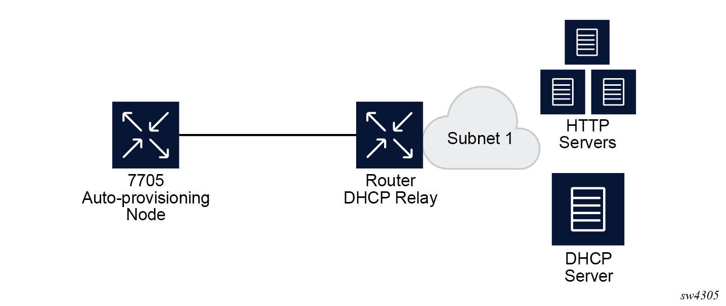
In Example of a network with a DHCP relay, there is a DHCP relay which injects the Option 82 as a gateway address. The DHCP server is assigned the IP address from the pool dictated by the gateway address option 82. The DHCP server and HTTP server are in the same subnet. The DHCP offer has option 3 "router" which is used for a default gateway creation on the 7705 SAR Gen 2.
In Example of a network with multiple subnets, all components are in different subnets. The DHCP relay adds Option 82 to the DHCP request as the gateway address which is used for pool selection. The DHCP server must add option 3 configured with the gateway address of the HTTP server.
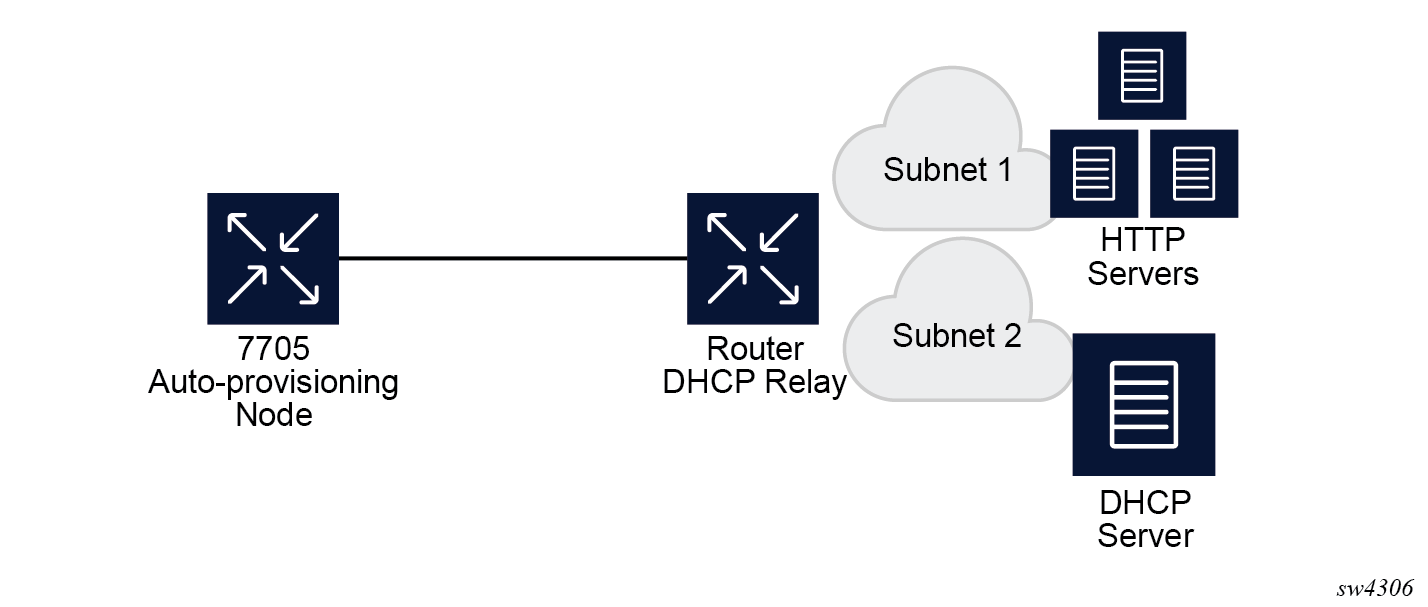
Auto-provisioning limits
The following are some configuration limits for auto-provisioning:
A maximum of 12 Layer 3 interfaces are supported for auto-provisioning.
Only IPv4 auto-provisioning is supported.
It is highly recommended to only have a basic card, MDA, port, and interface configuration as described in this document and no additional static routes or IGP or BGP protocols when performing auto-provisioning because auto-provisioning installs default static routes that may be affected by any extra routing configuration.
A maximum of 255 characters is supported for the remote URL (200 character maximum for the filepath, the rest for the main URL consisting of the protocol, login credentials, and host IP). A maximum of 200 characters is supported for the local URL. The local file or folder name must not exceed 99 characters.
The maximum number of file pairs for each image/config record is 10.
Auto-provisioning process
In this process, the node detects operational ports, attempts to discover its IP address, and downloads the relevant files for provisioning.
The node sends a DHCP discovery request to the DHCP server using the out-of-band management port. If DHCP discovery is unsuccessful, the node reattempts it using the in-band management ports.
After DHCP discovery is successful, the DHCP server returns an IPv4 or IPv6 FTP or HTTP URL of a file server from which the node can retrieve provisioning information.
The node downloads the provisioning information and performs the auto-provisioning according to the specifications in the files.
After the node is successfully provisioned, it automatically reboots and becomes operationally up.
See Provisioning files for more information about the auto-provisioning process.
The SR OS can also initiate the auto-provisioning process using a tools command.
Auto-provisioning DHCP rules
The following are the DHCP rules in the auto-provisioning stage:
First, auto-provisioning walks through the interfaces with a configured port, where the port is in operational status up, one by one.
It sends a DHCP request to the first configured interface with a port up and no IP address configured.
-
If, on this interface, multiple DHCP offers arrives, only the first offer is sent to the auto-provisioning task and the other offers are ignored. This could occur if the node is on a LAN and multiple DHCP servers are connected to the interface.
-
The DHCP client has an exponential retry mechanism. If the DHCP offer does not arrive from the server, the client resends a DHCP request at 2, 4, 8, 32 and 64 s, with 64 s being the maximum timeout, If the 64 s timeout interval is reached, the DHCP client keeps retrying every 64 s. The user can configure a timeout value. If no DHCP offer has arrived by this timeout value, the auto-provisioning process moves to the next interface.
-
If the DHCP offer arrives on the port and the DHCP client task does not acknowledge the DHCP offer, for any reason, it disables the DHCP client and remove the IP from the port.
-
If the DHCP offer arrives on the port and the DHCP client acknowledges the offer, it sends the information to auto-provisioning. If auto-provisioning does not like the offer, because there is no Option 67, Option 67 is malformed, or for any other reason listed in Auto-provisioning failure, the auto-provisioning process deconfigures the DHCP client and the DHCP client sends a DHCP release, and unassigns the IP address.
-
In case of failure, more information is displayed by the auto-provisioning process and the process moves to the next port that is up and does not have an IP address.
-
If auto-provisioning is successful using the offer and its option, the provisioning file download starts though the protocol dictated by Option 67.
The auto-provisioning command is CLI blocking. All information about the auto-provisioning process is displayed on the CLI and logged.
Auto-provisioning failure
Auto-provisioning fails for the following reasons:
There is no Option 67.
The Option 67 format is not acceptable to auto-provisioning.
The format is a URL or DNS is not supported. There is a failure in the download provisioning file or the server is not reachable.
There is failure in the download of the image or config file using the provisioning file information, for example, the server is not available, the wrong directory is listed, or the wrong credentials are given.
The image or config fails to copy to the compact flash.
The image or config fails to sync to the inactive CPM.
The BOF does not point to the compact flash, for example, it is pointing to the network.
If the auto-provisioning procedure on this interface fails, then auto-provisioning does the following:
Displays information about the blocked CLI and in the log, describing the failure in detail.
Updates the DHCP task so the DHCP task can take the appropriate actions to release the IP address on the interface. This is done by sending a DHCP release for the DHCP ack received from the server.
Goes to the next interface with port up and no IP address.
Note: If no other interface with port up is found, the auto-provisioning task stops and a failure error is displayed on the CLI and in the log.
Administrative tasks
This section contains information to perform administrative tasks.
Saving configurations
Whenever configuration changes are made, the modified configuration must be saved so they are not lost when the system is rebooted.
Configuration files are saved by executing explicit command syntax which includes the file URL location to save the configuration file as well as options to save both default and non-default configuration parameters. Boot option file (BOF) parameters specify where the system should search for configuration and image files as well as other operational parameters during system initialization.
For more information about boot option files, see the Boot Options section.
Specifying post-boot configuration files
Two post-boot configuration extension files are supported and are triggered when either a successful or failed boot configuration file is processed. The boot-bad-exec and boot-good-exec commands specify URLs for the CLI scripts to be run following the completion of the bootup configuration. A URL must be specified or no action is taken.
For example, after a configuration file is successfully loaded, the specified URL can contain a nearly identical configuration file with specific commands enabled or disabled, or particular parameters specified and according to the script which loads that file.
Network timing
In Time Domain Multiplexed (TDM)-based networks (for example, SONET or SDH circuit- switched networks), the concept of network timing is used to prevent over-run or under-run issues where circuits are groomed (rebundled) and switched. Hardware exists in each node that takes a common clock derived from an internal oscillator, a specific receive interface, or special BITS interface and provides it to each synchronous interface in the system. Usually, each synchronous interface is allowed to choose between using the chassis-provided clock or the clocking recovered from the received signal on the interface. The clocking is used to drive the transmit side of the interface. The appropriate configuration at each node which defines how interface clocking is handled must be considered when designing a network that has a centralized timing source so each interface is operating in a synchronous manner.
The effect of timing on a network is dependent on the nature of the type of traffic carried on the network. With bit-wise synchronous traffic (traditional circuit-based voice or video), non-synchronous transmissions cause a loss of information in the streams affecting performance. With packet-based traffic, the applications expect and handle jitter and latency inherent to packet-based networks. When a packet-based network is used to carry voice or video traffic, the applications use data compression and elasticity buffering to compensate for jitter and latency. The network itself relies on appropriate Quality of Service (QoS) definitions and network provisioning to further minimize the jitter and latency the application may experience.
Power supplies
SR OS supports a power-supply command to configure the type and number of power supplies present in the chassis. The operational status of a power source is always displayed by the LEDs on the Control Processor/Switch Fabric Module (CP/SFM) front panel, but the power supply information must be explicitly configured in order for a power supply alarm to be generated if a power source becomes operationally disabled.
System router instances
SR OS supports multiple Layer 3 router instances. These instances have their own IP addressing spaces and configuration options. Router instances are isolated from each other.
The following are the different types of router instances in SR OS:
Base
All SR OS routers have the base router instance: the system created default router instance used to forward user IP traffic among router line card ports. Router interfaces (that is, network interfaces configured under configure router [Base]) and IES services and interfaces exist in the base router instance. The base router instance is identified in SNMP as vRtrType = baseRouter (1) and has a vRtrID of 1.
VPRN instances
Another type of router instance is the set of operator configured VPRN services. Each VPRN service has a unique router instance. For more information about VPRN services and their associated router instances, see the 7705 SAR Gen 2 Layer 3 Services Guide: IES and VPRN. VPRN router instances are identified in SNMP as vRtrType = vprn (2), and the vRtrID is dynamically allocated.
Special system router instances
SR OS routers also support the following special router instances:
management
The management router instance is a system created router instance that is used for management of the router. The management router instance is bound to CPM/CCM ports A/1 and B/1. This is a CPM router instance which cannot be renamed or deleted by an operator. The management router instance is identified in SNMP as vRtrType = vr(3), and the vRtrID is 4095.
vpls-management
The vpls-management router instance is used for management of VPLS services. It is identified in SNMP as vRtrType = vr(3), and the vRtrID is 4094.
User created CPM router instances
User created CPM router instances are user defined router instances that are mainly used with Ethernet ports on the CPM/CCM cards: CPM router instances only use CPM/CCM Ethernet ports as interfaces. CPM router instances have a user-defined name and are the only types of non-VPRN router instances that can be created by the user. User created CPM router instances are identified in SNMP as vRtrType = vr(3), and the vRtrID is dynamically allocated.
Some management protocols can use either the base routing instance (in-band) or the management routing instance (out-of-band). A listing of these protocols can be found in the CPM Filter: Protocols and Ports section of the 7705 SAR Gen 2 System Management Guide. Unless otherwise stated in the detailed description of the protocol, when the server or client for the protocol is reachable via the management routing instance, those protocol messages use the management interface for the protocol communication.
If BOF is set up with autoconfiguration and the DHCP server provides a general default route such as 0.0.0.0/0, with some protocols (like PCEP, TACACS+, RADIUS, and LDAP), Authentication, Authorization, Accounting (AAA) always prefers OOB over in-band connectivity. This is because these protocols prefer to use the OOB management port first. If a matching route is not found, in-band is attempted. The static route provided by DHCP must be properly set to ensure the correct route preference is made by these protocols.
System configuration process overview
The following figure shows the process for basic system provisioning.
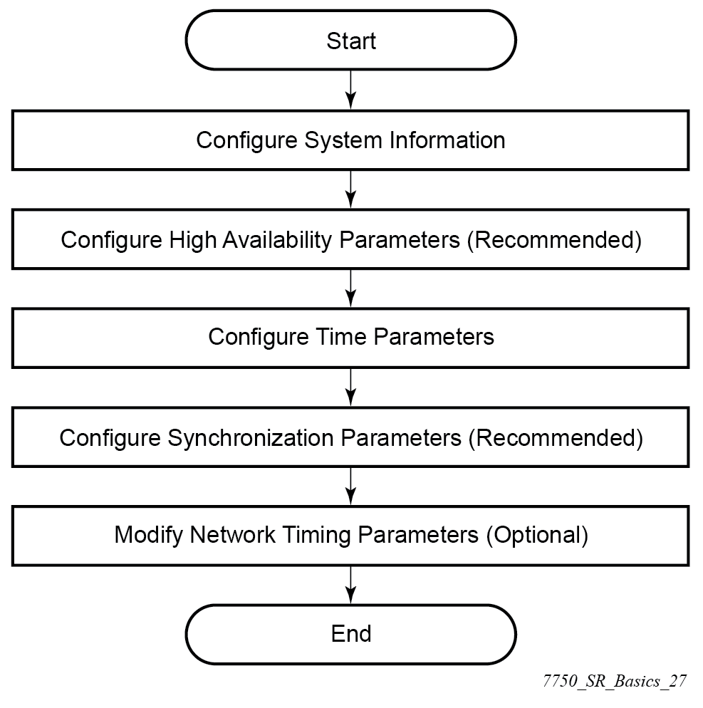
Saving configurations manually
Whenever configuration changes are made, the modified configuration must be saved so the changes are persistent when the system is rebooted. The system uses the configuration and image files, as well as other operational parameters necessary for system initialization, according to the locations specified in the boot option file (BOF) parameters. For more information about BOFs, see the System initialization and boot options chapter of this manual.
Configuration files can be manually saved in two ways with the admin save command:
-
When a location is specified as a parameter after the command, the system saves the configuration to the file URL that is entered.
- When a location is not specified, the system saves the configuration to the current BOF primary configuration location. If the primary configuration location (path or filename) has changed since the last boot, the new configuration location is used.
If the save attempt fails to the primary location, the system does not try to save the file to the secondary or tertiary configuration locations unless the path and filename are explicitly specified with the admin save command.
The classic CLI provides additional options for saving the configuration that are not needed in the MD-CLI. See the specific command descriptions in the 7705 SAR Gen 2 Classic CLI Command Reference Guide for more information.
Common configuration tasks
This section provides an overview of the CLI commands used to configure system parameters:
System information
This section describes the basic system information commands that configure the system name of the router, contact information, location (such as an address, floor, room number, and so on), CLLI code, and global positioning system (GPS) coordinates.
System name
The device's system name is used in the prompt string. Only one system name can be configured; if multiple system names are configured, the last one overwrites the previous entry.
Use the following command to configure the system name.
configure system nameContact
Use the contact command to specify the name of a system administrator, IT staff member, or other administrative entity.
Use the following command to configure the contact.
configure system contactLocation
Use the location command to specify the location of the device. For example, enter the city, building address, floor, room number, and so on, where the router is located.
Use the following command to configure the location.
configure system locationCLLI code
The Common Language Location Code (CLLI code) is an 11-character standardized geographic identifier that is used to uniquely identify the geographic location of a router.
Use the following command to configure the CLLI code.
configure system clli-codeGPS coordinates
Use the optional coordinates command to specify the GPS location of the device. If the string contains special characters (#, $, spaces, and so on), the entire string must be enclosed within double quotes.
Use the following command to configure the coordinates.
configure system coordinatesSystem time elements
The system clock maintains time according to Coordinated Universal Time (UTC). Configure the time zone and summer time (daylight saving time) command options to correctly display time according to the local time zone.
Zone
The zone command sets the time zone and time zone UTC offset for the router. SR OS supports system-defined and user-defined time zones. The system-defined time zones and offsets are listed in System-defined time zones and UTC offsets.
configure system time zoneSummer (daylight saving) time
Configure the start and end dates and offset for summer (daylight saving) time to override system defaults or for user-defined time zones. When configured, the time will be adjusted by changing to the configured offset when summer time starts and returning to the configured offset when summer time ends.
Use commands in the following context to configure the start day, end day, and offset of the summer.
configure system time dst-zoneIf the time zone configured is listed in System-defined time zones and UTC offsets, the start and end command options and offset do not need to be configured with this command unless there is a need to override the system defaults. The command will return an error if the start and end dates and times are not available either in System-defined time zones and UTC offsets or entered as optional command options in this command.
NTP
NTP is the Network Time Protocol defined in RFC 1305, Network Time Protocol (Version 3) Specification, Implementation and Analysis and RFC 5905, Network Time Protocol Version 4: Protocol and Algorithms Specification. It allows for the participating network nodes to keep time more accurately and more importantly they can maintain time in a more synchronized fashion between all participating network nodes.
SR OS uses an NTP process based on a reference build provided by the Network Time Foundation. Nokia strongly recommends that the users review RFC 8633, Network Time Protocol Best Current Practices, when they plan to use NTP with the router. The RFC section ‟Using Enough Time Sources” indicates that using only two time sources (NTP servers) can introduce instability if they provide conflicting information. To maintain accurate time, Nokia recommends configuring three or more NTP servers.
NTP uses stratum levels to define the number of hops from a reference clock. The reference clock is considered to be a stratum-0 device that is assumed to be accurate with little or no delay. Stratum-0 servers cannot be used in a network. However, they can be directly connected to devices that operate as stratum-1 servers. A stratum-1 server is an NTP server with a directly-connected device that provides Coordinated Universal Time (UTC), such as a GPS or atomic clock.
The higher stratum levels are separated from the stratum-1 server over a network path, therefore, a stratum-2 server receives its time over a network link from a stratum-1 server. A stratum-3 server receives its time over a network link from a stratum-2 server.
SR OS routers normally operate as a stratum-2 or higher device. The router relies on an external stratum-1 server to source accurate time into the network. However, SR OS also allows for the use of the local PTP recovered time to be sourced into NTP. In this latter case, the local PTP source appears as a stratum-0 server and SR OS advertises itself as a stratum-1 server. Activation of the PTP source into NTP may impact the network NTP topology because the SR OS router is promoted to stratum-1.
SR OS router runs a single NTP clock which then operates NTP message exchanges with external NTP clocks. Exchanges can be made with external NTP clients, servers, and peers. These exchanges can be through the base, management, or VPRN routing instances.
NTP operates associations between clocks as either client or server, symmetric active and symmetric passive, or broadcast modes. These modes of operation are applied according to which elements are configured on the router. To run server mode, the operator must enable NTP server mode for the base and each needed VPRN routing instance. To run client mode, the operator must configure external servers. If both the local router and remote router are configured with each other as peers, then the router operates in symmetric active mode. If only one side of the association has peering configured, then the modes are symmetric passive. To operate using broadcast mode, interfaces must be configured to transmit as broadcast servers or receive as broadcast clients.
NTP server operation for both unicast and broadcast communication within a VPRN is configured within the VPRN (see "NTP Within a VPRN Service" in the 7705 SAR Gen 2 Layer 3 Services Guide: IES and VPRN).
The following NTP elements are supported:
-
server mode
In this mode, the node advertises the ability to act as a clock source for other network elements. The node, by default, transmits NTP packets in NTP version 4 mode.
-
authentication keys
Authentication keys implement increased security support in carrier and other networks. Both DES and MD5 authentication are supported, as well as multiple keys.
-
operation in symmetric active mode
This capability requires that NTP be synchronized with a specific node that is considered more trustworthy or accurate than other nodes carrying NTP in the system. This mode requires that a specific peer is set.
-
server and peer addressing using IPv6
Both external servers and external peers may be defined using IPv6 or IPv4 addresses. Other features (such as multicast, broadcast) use IPv4 addressing only.
-
broadcast or multicast modes
When operating in these modes, the node receives or sends using either a multicast (default 224.0.1.1) or a broadcast address. Multicast is supported only on the CPM MGMT port.
-
alert when NTP server is not available
When none of the configured servers are reachable on the node, the system reverts to manual timekeeping and issues a critical alarm. When a server becomes available, a trap is issued indicating that standard operation has resumed.
-
NTP and SNTP
If both NTP and SNTP are enabled on the node, then SNTP transitions to an operationally down state. If NTP is removed from the configuration or shut down, then SNTP resumes an operationally up state.
-
gradual clock adjustment
As several applications (such as Service Assurance Agent (SAA)) can use the clock, and if determined that a major (128 ms or more) adjustment needs to be performed, the adjustment is performed by programmatically stepping the clock. If a minor (less than 128 ms) adjustment must be performed, then the adjustment is performed by either speeding up or slowing down the clock.
-
To avoid the generation of too many events/trap the NTP module rates limit the generation of events/traps to three per second. At that point a single trap is generated that indicates that event/trap squashing is taking place.
Authentication-check
NTP supports an authentication mechanism to provide some security and access control to servers and clients. The authentication check feature provides the option to skip the rejection of NTP PDUs that do not match the authentication key or authentication type requirements.
The default behavior when authentication is configured is to reject all NTP PDUs that have a mismatch in either the authentication key ID, type, or key.
When authentication check is configured, NTP PDUs are authenticated on receipt. However, mismatches cause a counter to be increased, one counter for key ID, one for type, and one for key value mismatches.
Use commands in the following context to enable authentication check.
configure system time ntp authentication-checkMD-CLI
[ex:/configure system time ntp]
A:admin@node-2# info
    admin-state enable
    authentication-check true
classic CLI
A:node-2>config>system>time>ntp# info
----------------------------------------------
                authentication-check
                no shutdown
----------------------------------------------
Authentication-key
The authentication-key command configures an authentication key ID, key type, and key used to authenticate NTP PDUs sent to and received from other network elements participating in the NTP. For authentication to work, the authentication key ID, authentication type, and authentication key value must match.
MD-CLI
[ex:/configure system time ntp]
A:admin@node-2# info
    admin-state enable
    authentication-key 1 {
        key "OAwgNUlbzgI hash2"
        type des
    }
classic CLI
A:node-2>config>system>time>ntp# info
----------------------------------------------
                shutdown
                authentication-key 1 key "OAwgNUlbzgI" hash2 type des
----------------------------------------------
Broadcast
The broadcast command is used to transmit broadcast packets on a given interface. Interfaces in the base routing context or the management interface may be specified. Due the relative ease of spoofing of broadcast messages, it is strongly recommended to use authentication with broadcast mode. The messages are transmitted using a destination address that is the NTP Broadcast address. The following example enables NTP and configures the broadcast interface.
MD-CLI
[ex:/configure system time ntp]
A:admin@node-2# info
    admin-state enable
    broadcast "Base" interface-name "int11" {
        version 4
        ttl 127
    }
classic CLI
A:node-2>config>system>time>ntp# info
----------------------------------------------
                broadcast interface int11 version 4 ttl 127
                no shutdown
----------------------------------------------
Broadcastclient
The broadcastclient command enables listening to NTP broadcast messages on the specified interface. Interfaces in the base routing context or the management interface may be specified. Due the relative ease of spoofing of broadcast messages, it is strongly recommended to use authentication with broadcast mode. The messages must have a destination address of the NTP Broadcast address. The following example enables NTP and configures the broadcast client.
MD-CLI
[ex:/configure system time ntp]
A:admin@node-2# info
    admin-state enable
    broadcast-client "Base" interface-name "int11" {
    }
classic CLI
A:node-2>config>system>time>ntp# info
----------------------------------------------
                broadcastclient interface int11
                no shutdown
----------------------------------------------
Multicast
When configuring NTP the node can be configured to transmit or receive multicast packets on the CPM MGMT port. Broadcast and multicast messages can easily be spoofed; therefore, authentication is strongly recommended. Multicast is used to configure the transmission of NTP multicast messages. When transmitting multicast NTP messages the default address of 224.0.1.1 is used. The following example enables NTP and multicast.
MD-CLI
[ex:/configure system time ntp]
A:admin@node-2# info
    admin-state enable
    multicast {
    }
classic CLI
A:node-2>config>system>time>ntp# info
----------------------------------------------
                multicast
                no shutdown
----------------------------------------------
Multicastclient
The multicastclient command is used to configure an address to receive multicast NTP messages on the CPM MGMT port. Broadcast and multicast messages can easily be spoofed, therefore, authentication is strongly recommended. If multicastclient is not configured, all NTP multicast traffic is ignored. The following example enables NTP and configures the address to receive multicast NTP messages.
MD-CLI
[ex:/configure system time ntp]
A:admin@node-2# info
    admin-state enable
    multicast-client {
        authenticate true
    }
classic CLI
A:node-2>config>system>time>ntp# info
----------------------------------------------
                multicastclient
                no shutdown
----------------------------------------------
NTP-server
The ntp-server command configures the node to assume the role of an NTP server. Unless the server command is used, this node will function as an NTP client only and will not distribute the time to downstream network elements. If the authenticate command option is specified, the NTP server requires client packets to be authenticated.
The following is an example of a configuration output of NTP enabled with the ntp-server command configured.
MD-CLI
[ex:/configure system time ntp]
A:admin@node-2# info
    admin-state enable
    ntp-server {
        authenticate true
    }
classic CLI
A:node-2>config>system>time>ntp# info
----------------------------------------------
        no shutdown
        ntp-server
----------------------------------------------
Peer
Configuration of an NTP peer configures symmetric active mode for the configured peer. Although any system can be configured to peer with any other NTP node, Nokia recommends configuring authentication and to configure known time servers as their peers. Administratively disable this command to remove the configured peer.
Use commands in the following context to configure symmetric active mode.
configure system time ntp peerMD-CLI
[ex:/configure system time ntp]
A:admin@node-2# info
    admin-state enable
    peer 192.168.1.1 router-instance "Base" {
        key-id 1
    }
classic CLI
A:node-2>config>system>time>ntp# info
----------------------------------------------
            no shutdown
            peer 192.168.1.1 key-id 1
----------------------------------------------
Server
The server command is used when the node should operate in client mode with the NTP server specified in the address field. Up to ten NTP servers can be configured. The following example enables NTP and configures the server.
MD-CLI
[ex:/configure system time ntp]
A:admin@node-2# info
    admin-state enable
    server 192.168.1.1 router-instance "Base" {
        key-id 1
    }
classic CLI
A:node-2>config>system>time>ntp# info
----------------------------------------------
                no shutdown
                server 192.168.1.1 key 1
----------------------------------------------
SNTP
SNTP is a compact, client-only version of NTP. SNTP can only receive the time from SNTP/NTP servers; it cannot be used to provide time services to other systems. SNTP can be configured in either broadcast or unicast client mode.
SNTP time elements include the Broadcast-client and Server-address.
Use the commands in the following context to configure the SNTP.
configure system time sntpBroadcast-client
- MD-CLI
configure system time sntp sntp-state broadcast - classic
CLI
configure system time sntp broadcast-client
The following example shows SNTP enabled with the broadcast client.
MD-CLI
[ex:/configure system time sntp]
A:admin@node-2# info
    admin-state enable
    sntp-state broadcast
classic CLI
A:node-2>config>system>time>sntp# info
----------------------------------------------
                broadcast-client
                no shutdown
----------------------------------------------
Server-address
- MD-CLI
configure system time sntp server - classic
CLI
configure system time sntp server-address
The following is an example of a configuration output of SNTP enabled with the server-address command configured.
MD-CLI
[ex:/configure system time sntp]
A:admin@node-2# info
    admin-state enable
    server 10.10.0.94 {
        version 1
        prefer true
        interval 100
    }
classic CLI
A:node-2>config>system>time>sntp# info
----------------------------------------------
                server-address 10.10.0.94 version 1 preferred interval 100
                no shutdown
----------------------------------------------
CRON
The CRON feature supports periodic and date and time-based scheduling in SR OS. CRON can be used, for example, to schedule Service Assurance Agent (SAA) functions. CRON functionality includes the ability to specify scripts that need to be run, when they are scheduled, including one-time only functionality (one-shot), interval and calendar functions. Scheduled reboots, peer turn ups, service assurance agent tests and more can all be scheduled with CRON, as well as OAM events, such as connectivity checks, or troubleshooting runs.
CRON supports the schedule element. The schedule function configures the type of schedule to run, including one-time only (one-shot), periodic, or calendar-based runs. All runs are determined by month, day of month or weekday, hour, minute, and interval (seconds).
Schedule
The schedule command configures the type of schedule to run, including one-time only (oneshot), periodic, or calendar-based runs. All runs are determined by month, day of the month or weekday, hour, minute, and interval (seconds). If the end-time and interval command options are both configured, whichever condition is reached first is applied.
The following is an example of a configuration output that schedules a script named ‟test” to run every 15 minutes on the 17th of each month and every Friday until noon on July 17, 2007.
MD-CLI
[ex:/configure system cron]
A:admin@node-2# info
    schedule "test" owner "TiMOS CLI" {
        day-of-month [17]
        minute [0 15 30 45]
        weekday [friday]
        end-time {
            date-and-time 2007-07-17T12:00:00.0+00:00
        }
    }
classic CLI
*A:node-2>config>system>cron# info
----------------------------------------------
        schedule "test"
            shutdown
            day-of-month 17
            minute 0 15 30 45
            weekday friday
            end-time 2007/07/17 12:00
        exit
----------------------------------------------
ANCP enhancements
Persistency is available for subscriber ANCP attributes and is stored on the on-board compact flash card. ANCP data stays persistent during an ISSU as well as node reboots. During recovery, ANCP attributes are first restored fully from the persistence file, and incoming ANCP sessions are temporarily on hold. Afterwards, new ANCP data can overwrite any existing values. This new data is then stored into the compact flash in preparation for the next event.
Configuration backups
You can specify the maximum number of configuration and classic CLI index backups stored in the configuration primary location.
For example, the maximum number of backups is set to 5 and the configuration file is called xyz.cfg. When the configuration is saved, the most recent file is renamed with a .1 extension. Each subsequent file increments the numeric extension until the maximum count is reached. The oldest file (5) is deleted as more recent files are saved.
-
config.cfg
-
config.cfg.1
-
config.cfg.2
-
config.cfg.3
-
config.cfg.4
-
config.cfg.5
Each persistent index file is updated at the same time as the associated configuration file. When the index file is updated, the save is performed to config.cfg and the classic CLI index file is created as config.ndx. Synchronization between the active and standby SF/CPMSF/CPM is performed for all configurations and their associated persistent index files.
Use the following commands to specify the maximum number of backup versions of the configuration and index files kept in the primary location:
- MD-CLI
configure system management-interface configuration-save configuration-backups - classic
CLI
configure system config-backup
The following example shows the command usage to set the maximum number of backup versions of the configuration and index files kept in the primary location to 7.
MD-CLI
[ex:/configure]
A:admin@node-2# system management-interface configuration-save configuration-backups 7
classic CLI
A:node-2# system config-backup 7Configuration backup configuration output (MD-CLI)
[ex:/configure system]
A:admin@node-2# info
    contact "Fred Information Technology"
    name "node-2"
    location "Bldg.1-floor 2-Room 201"
    coordinates "N 45 58 23, W 34 56 12"
    clli-code "abcdefg1234"
...
 management-interface {
        configuration-save {
            configuration-backups 7
        }
...
Configuration backup configuration output (classic CLI)
A:node-2>config>system>time# info
#------------------------------------------
echo "System Configuration"
#------------------------------------------
        name "node-2"
        contact "Fred Information Technology"
        location "Bldg.1-floor 2-Room 201"
        clli-code "abcdefg1234"
        coordinates "N 45 58 23, W 34 56 12"
        config-backup 7
...
----------------------------------------------
System timing
When network timing is required for synchronous interfaces in the router, a timing subsystem provides a clock to all synchronous interfaces within the system.
This section describes the commands used to configure and control the timing subsystem.
Entering edit mode
Use the following command to enter the edit mode and edit timing references.
configure system sync-if-timing beginThe following is an example of an error message that is displayed if you try to modify sync-if-timing parameters without entering the begin keyword.
A:node-2>config>system>sync-if-timing>ref1# source-port 2/1/1
MINOR: CLI The sync-if-
timing must be in edit mode by calling begin before any changes can be made.
MINOR: CLI Unable to set source port for ref1 to 2/1/1.
A:node-2>config>system>sync-if-timing>ref1#
Configuring timing references
Use commands in the following context to configure timing reference settings:
- MD-CLI
configure system central-frequency-clock - classic
CLI
configure system sync-if-timing
The source port specified for ref1 and ref2 is dependent on the router model type and chassis slot.
Using the revert command
The revert function allows the clock to revert to a higher-priority reference if the current reference goes offline or becomes unstable.
When mode is non-revertive, a failed clock source is not selected again. If a node enters holdover because the references are in a previously failed state, the revertive switching mode enables the node to select one of the previously failed references, instead of going into holdover.
- MD-CLI
configure system central-frequency-clock revert true - classic
CLI
configure system sync-if-timing revert
- MD-CLI
configure system central-frequency-clock revert false - classic
CLI
configure system sync-if-timing no revert
Committing and discarding changes
Use the following command to save changes made to the timing references during a session. Modifications are not persistent across system boots unless this command is used.
- MD-CLI
configure system central-frequency-clock commit - classic
CLI
configure system sync-if-timing commit
Use the following command to discard changes that have been made to the timing references during a session:
- MD-CLI
configure system central-frequency-clock discard - classic
CLI
configure system sync-if-timing abort
Forcing a specific reference
The debug sync-if-timing force-reference command should only be used to test and debug problems. Network synchronization problems may appear if network elements are left with this manual override setting. When the system timing reference input has been forced, it may be cleared using the no force-reference command.
Force the CPM clock to use a specific input reference using the force-reference command.
When the command is executed, the CPM clock on the active CPM immediately switches its input reference to that specified by the command. If the specified input is not available (shutdown), or in a disqualified state, the CPM clock shall use the next qualified input reference based on the selection rules.
On a CPM activity switch, the force command is cleared and normal reference selection is determined.
Configuring system timing to use a GNSS RF port
Use the following command to configure a GNSS RF port as a system timing reference:
- MD-CLI
configure system central-frequency-clock gnss admin-state enable - classic
CLI
configure system sync-if-timing gnss no shutdown
Timing reference configuration (MD-CLI)
[ex:/configure system central-frequency-clock]
A:admin@node-2# info
    gnss {
        admin-state enable
    }
Timing reference configuration (classic CLI)
A:node-2>config>system>sync-if-timing# info
----------------------------------------------
            gnss
               no shutdown
            exit
----------------------------------------------
Configuring power supply
The 7705 SAR-1, 7705 SAR-Hx, and 7705 SAR-Mx support component redundancy for the power supply feeds. The use of up to two power supply feeds for 1+1 power redundancy is supported. A power feed can fail without impacting traffic when a redundant power feed configuration is in use.
The following outputs show the chassis power supply information on 7705 SAR Gen 2 platforms.
Power supply information on 7705 SAR-1
A:node-2 show chassis power-supply
===============================================================================
Chassis 1 Detail
===============================================================================
Power Supply Information
  Number of power supplies          : 2

  Power supply number               : 1
    Power supply type               : ac single
    Status                          : up
    AC power                        : within range
    DC power                        : within range

  Power supply number               : 2
    Power supply type               : ac single
    Status                          : up
    AC power                        : within range
    DC power                        : within range
===============================================================================
Power supply information on 7705 SAR-Hx
A:node:2# show chassis power-supply
===============================================================================
Chassis 1 Detail
===============================================================================
Power Supply Information
  Number of power supplies          : 2

  Power supply number               : 1
    Power supply type               : ac single
    Power supply model              : peq
    Status                          : up
    AC power                        : within range
    DC power                        : within range
    Over temp                       : within range
    Hardware Data
      Part number                   : 3HE20432AARA01
      CLEI code                     : INPSAJ6FAA
      Serial number                 : NS2531XI371
      Manufacture date              : 08042025
      Manufacturing deviations      : (Not Specified)
      Manufacturing assembly number :
      Administrative state          : up
      Operational state             : up
      Time of last boot             : N/A
      Current alarm state           : alarm cleared

  Power supply number               : 2
    Power supply type               : ac single
    Power supply model              : peq
    Status                          : up
    AC power                        : within range
    DC power                        : within range
    Over temp                       : within range
    Hardware Data
      Part number                   : 3HE20432AARA01
      CLEI code                     : INPSAJ6FAA
      Serial number                 : NS2535XL610
      Manufacture date              : 09172025
      Manufacturing deviations      : (Not Specified)
      Manufacturing assembly number :
      Administrative state          : up
      Operational state             : up
      Time of last boot             : N/A
      Current alarm state           : alarm cleared
===============================================================================
Power supply information on 7705 SAR-Mx
A:node:2# show chassis power-supply
===============================================================================
Chassis 1 Detail
===============================================================================
Power Supply Information
  Number of power supplies          : 2

  Power supply number               : 1
    Power supply type               : ac single
    Power supply model              : peq
    Status                          : up
    AC power                        : within range
    DC power                        : within range
    Over temp                       : within range
    Hardware Data
      Part number                   : 3HE20432AARA01
      CLEI code                     : INPSAJ6FAA
      Serial number                 : NS2546XT816
      Manufacture date              : 11112025
      Manufacturing deviations      : (Not Specified)
      Manufacturing assembly number :
      Administrative state          : up
      Operational state             : up
      Time of last boot             : N/A
      Current alarm state           : alarm cleared

  Power supply number               : 2
    Power supply type               : ac single
    Power supply model              : peq
    Status                          : up
    AC power                        : within range
    DC power                        : within range
    Over temp                       : within range
    Hardware Data
      Part number                   : 3HE20432AARA01
      CLEI code                     : INPSAJ6FAA
      Serial number                 : NS2535XL610
      Manufacture date              : 09172025
      Manufacturing deviations      : (Not Specified)
      Manufacturing assembly number :
      Administrative state          : up
      Operational state             : up
      Time of last boot             : N/A
      Current alarm state           : alarm cleared
===============================================================================
Configuring multichassis redundancy for LAG
When configuring the associated LAG ID, the LAG must be in access mode and LACP must be enabled. The following example configures multichassis redundancy features.
MD-CLI
[ex:/configure redundancy multi-chassis]
A:admin@node-2# info
    peer 10.10.10.2 {
        admin-state enable
        description "Mc-Lag peer 10.10.10.2"
        mc-lag {
            admin-state enable
            lag "lag-1" {
                lacp-key 32666
                system-id 00:00:00:33:33:33
                system-priority 32888
            }
        }
    }
classic CLI
A:node-2>config>redundancy>multi-chassis# info
---------------------------------------------
        peer 10.10.10.2 create
            description "Mc-Lag peer 10.10.10.2"
            mc-lag
                no shutdown
            exit
            no shutdown
        exit
---------------------------------------------
Post-boot configuration extension files
Two post-boot configuration extension files are supported and are triggered when either a successful or failed boot configuration file is processed. The commands specify URLs for the CLI scripts to be run following the completion of the startup configuration. A URL must be specified or no action is taken. The commands are persistent between router reboots and are included in the configuration saves.
Use the following commands to specify the CLI scripts that are run following the completion of the boot-up configuration.
configure system boot-bad-exec
configure system boot-good-exec
Show command output and console messages
Use the following command to show the current value of the bad and good exec URLs and indicate whether a post-boot configuration extension file was executed when the system was booted.
show system informationIf an extension file was executed, the command also indicates whether it completed successfully.
The following example shows the show output for the 7705 SAR-1.
Show system information output for the 7705 SAR-1
===============================================================================
System Information
===============================================================================
System Name            : node-2
System Type            : 7705 SAR-1
...
BOF Source             : cf3:
Image Source           : primary
Config Source          : N/A
Last Booted Config File: N/A
Last Boot Cfg Version  : N/A
Last Boot Config Header: N/A
Last Boot Index Version: N/A
Last Boot Index Header : N/A
Last Saved Config      : ftp://test:test@192.168.xx.xxx/./images/dut-bg.cfg
Time Last Saved        : 2025/03/27 20:12:15
Changes Since Last Save: No
User Last Modified     : admin
Max Cfg/BOF Backup Rev : 5
Cfg-OK Script          : ftp://test:test@192.168.xx.xxx/./images/env.cfg
Cfg-OK Script Status   : success
Cfg-Fail Script        : N/A
Cfg-Fail Script Status : not used
...
===============================================================================
When executing a post-boot configuration extension file, status messages are displayed on the console before the ‟Login” prompt.
The following example shows a failed bootup configuration that caused a boot-bad-exec file containing another error to be executed.
Failed start-up configuration error message
Attempting to exec configuration file:
’ftp://test:test@192.168.xx.xxx/./12.cfg’ ...
System Configuration
Log Configuration
MAJOR: CLI #1009 An error occurred while processing a CLI command -
File ftp://test:test@192.168.xx.xxx/./12.cfg, Line 195: Command "log" failed.
CRITICAL: CLI #1002 An error occurred while processing the configuration file.
The system configuration is missing or incomplete.
MAJOR: CLI #1008 The SNMP daemon is disabled.
If desired, enable SNMP with the ’config>system>snmp no shutdown’ command.
Attempting to exec configuration failure extension file:
’ftp://test:test@192.168.xx.xxx/./fail.cfg’ ...
Config fail extension
Enabling SNMP daemon
MAJOR: CLI #1009 An error occurred while processing a CLI command -
File ftp://test:test@192.168.xx.xxx/./fail.cfg, Line 5: Command "abc log" failed.
TiMOS-B-x.0.Rx both/hops ALCATEL Copyright (c) 2000-20011 Alcatel-Lucent.
All rights reserved. All use subject to applicable license agreements.
Built on Thu Nov 207 19:19:11 PST 2008 by builder in /rel5x.0/b1/Rx/panos/main


Login:
Configuring system monitoring thresholds
This section provides information about configuring system monitoring thresholds.
Creating events
The event command controls the generation and notification of threshold crossing events configured with the alarm and hc-alarm (high capacity) commands. When a threshold crossing event is triggered, the rmon event configuration optionally specifies whether an entry in the alarm table is created to record the occurrence of the event. It can also specify whether an SNMP trap be generated for the event. There are two notifications for threshold crossing events: a rising alarm and a falling alarm.
Creating an event entry in the alarm table does not create a corresponding entry in the event logs. However, when the event is set to trap, the generation of a rising alarm or falling alarm notification creates an entry in the event logs and that is distributed to whatever log destinations are configured: console, session, memory, file, syslog, or SNMP trap destination. The log message includes a rising or falling threshold crossing event indicator, the sample type (absolute or delta), the sampled value, the threshold value, the RMON alarm ID, the associated RMON event ID, and the sampled SNMP object identifier.
The alarm command configures an entry in the RMON-MIB::alarmTable. The hc-alarm command configures an entry in the HC-ALARM-MI:: hcAlarmTable. These commands control the monitoring and triggering of threshold crossing events. For notification or logging of a threshold crossing event to occur, there must be at least one associated rmon event configured.
The agent periodically takes statistical sample values from the MIB OID specified for monitoring and compares them to thresholds that have been configured. The alarm and hc-alarm commands configure the MIB OID to be monitored, the polling period (interval), sampling type (absolute or delta value), and rising and falling threshold parameters. If a sample has crossed a threshold value, the associated event is generated.
Preconfigured CLI threshold commands are available. Preconfigured commands hide some of the complexities of configuring RMON alarm and event commands and perform the same function. The preconfigured commands do not require the user to know the SNMP object identifier to be sampled. The preconfigured threshold configurations include memory warnings and alarms and compact flash usage warnings and alarms.
MD-CLI
[ex:/configure system thresholds]
A:admin@node-2# info
    cflash-cap-warn-percent "cf1-B:" {
        rising-threshold 100
        falling-threshold 50
        interval 240
        startup-alarm either
    }
    kb-memory-use-alarm {
        rising-threshold 50000000
        falling-threshold 45999999
        interval 500
        startup-alarm either
    }
    rmon {
        event 5 {
            description "alarm testing"
            owner "Timos CLI"
        }
    }
classic CLI
A:node-2>config>system>thresholds# info
----------------------------------------------
            rmon
                event 5 description "alarm testing" owner "Timos CLI"
            exit
            cflash-cap-warn cf1-B: rising-threshold 2000000 falling-threshold
1999900 interval 240 trap
            memory-use-alarm rising-threshold 50000000 falling-threshold
45999999 interval 500
----------------------------------------------
Configuring LLDP
Use the commands in the following context to configure LLDP.
configure system lldpLLDP default configuration (MD-CLI)
[ex:/configure system lldp]
A:admin@node-2# info detail
 ## apply-groups
 ## apply-groups-exclude
    admin-state enable
    tx-credit-max 5
    message-fast-tx 1
    message-fast-tx-init 4
    tx-interval 30
    tx-hold-multiplier 4
    reinit-delay 2
    notification-interval 5
LLDP default configuration (classic CLI)
A:node-2>config>system>lldp# info detail
----------------------------------------------
             no tx-interval
             no tx-hold-multiplier
             no reinit-delay
             no notification-interval
             no tx-credit-max
             no message-fast-tx
             no message-fast-tx-init
             no shutdown
----------------------------------------------
LLDP port configuration (MD-CLI)
[ex:/configure port 1/1/1 ethernet lldp]
A:admin@node-2# info
    dest-mac nearest-bridge {
        receive true
        transmit true
        tx-tlvs {
            port-desc true
            sys-cap true
        }
        tx-mgmt-address system {
            admin-state enable
        }
    }
LLDP port configuration (classic CLI)
A:node-2>config>port>ethernet>lldp# info
----------------------------------------------
       dest-mac nearest-bridge
              admin-status tx-rx
              tx-tlvs port-desc sys-cap
              tx-mgmt-address system
       exit
----------------------------------------------
Global system LLDP configuration (MD-CLI)
[ex:/configure system lldp]
A:admin@node-2# info
    tx-interval 10
    tx-hold-multiplier 2
    reinit-delay 5
    notification-interval 10
Global system LLDP configuration (classic CLI)
A:node-2>config>system>lldp# info
----------------------------------------------
        tx-interval 10
        tx-hold-multiplier 2
        reinit-delay 5
        notification-interval 10
----------------------------------------------
Monitoring datapath statistics
This section provides information about monitoring datapath statistics on the 7705 SAR Gen 2.
Virtual FP utilization
The 7705 SAR Gen 2 allocates CPU cores to different system tasks based on the active system profile. See System profiles for more information about system profiles.
Use the following command to display the virtual FP utilization for each task.
show card virtual fpVirtual FP utilization on profile A
===============================================================================
Card 1 Virtual Forwarding Plane Statistics
===============================================================================
Task                   vCPUs            Average        Maximum
                                        Utilization    Utilization
-------------------------------------------------------------------------------
NIC                    2                0.00 %         0.00 %
Worker                 8                0.04 %         0.04 %
Scheduler              1                0.00 %         0.00 %
BufferMgr              1                8.06 %         8.06 %
===============================================================================
Buffer pools and congestion status
Use the following command to display buffer pool utilization and congestion status.
tools dump system congestion-status cardBuffer pool utilization and congestion status
===============================================================================
System congestion status
===============================================================================
Settings
Packet size                                      : jumbo
Early discard                                    : disabled

Packet pool
Average free buffers (%)                         : 96
Current free buffers                             : 410436 / 411395

Congestion status
Current                                          : not-congested
Last second                                      : not-congested
Last minute                                      : not-congested
Last 5 minutes                                   : not-congested
Last 30 minutes                                  : not-congested
===============================================================================
FP input-output statistics
The 7705 SAR Gen 2 supports displaying FP input-output statistics at the port, MDA, or card level. In the MD-CLI, state commands also provide the ability to display counters for individual statistics.
In the MD-CLI, use the commands in the following contexts to display individual statistics counters.
state port fp input-output statistics
state mda fp input-output statistics
state card fp input-output statistics
Use the commands in the following contexts to display aggregated FP statistics.
tools dump port fp input-output statistics
tools dump mda fp input-output statistics
tools dump card fp input-output statistics
In the port context, the commands display per-port FP statistics. The commands are supported on all embedded Ethernet ports. For per-port statistics, the router supports displaying either the cumulative statistics since the last system reboot, or the statistics accumulated since they were last cleared using the clear port fp input-output statistics command. The latter is useful for debugging purposes.
In the mda context, the commands display the aggregated FP statistics of all ports on the specified MDA. These commands are supported for all MDAs. Unlike with ports, the aggregated MDA FP statistics cannot be cleared directly. However, using the clear port command to clear the information on a specific MDA (for example, 1/1) also clears the FP utilization statistics for that MDA.
In the card context, the commands display the aggregated statistics of all ports for all MDAs on the card. These statistics cannot be cleared.
The following output shows the state FP statistics counters available for monitoring at the card level.
state card fp input-output statistics
[/state card 1 fp 1 input-output statistics cumulative]
A:admin@node-2# tree
+-- congestion-group-rejected-bytes
+-- congestion-group-rejected-frames
+-- egress-broadcast-bytes
+-- egress-broadcast-frames
+-- egress-confirmed-frames
+-- egress-discarded-frames
+-- egress-multicast-bytes
+-- egress-multicast-frames
+-- ingress-broadcast-bytes
+-- ingress-broadcast-frames
+-- ingress-discarded-frames
+-- ingress-filtered-frames
+-- ingress-multicast-bytes
+-- ingress-multicast-frames
+-- ingress-no-buffer-discards
+-- mac-rx-alignment-errors
+-- mac-rx-all-bytes
+-- mac-rx-all-frames
+-- mac-rx-broadcast-frames
+-- mac-rx-bytes
+-- mac-rx-control-frames
+-- mac-rx-discarded-frames
+-- mac-rx-fcs-errors
+-- mac-rx-fragmented-frames
+-- mac-rx-frame-discards-not-truncated
+-- mac-rx-frame-errors
+-- mac-rx-frame-ok
+-- mac-rx-frames-1024-to-1518-bytes
+-- mac-rx-frames-128-to-255-bytes
+-- mac-rx-frames-1519-to-max-bytes
+-- mac-rx-frames-256-to-511-bytes
+-- mac-rx-frames-512-to-1023-bytes
+-- mac-rx-frames-64-bytes
+-- mac-rx-frames-65-to-127-bytes
+-- mac-rx-jabber-frames
+-- mac-rx-multicast-frames
+-- mac-rx-oversized-frames
+-- mac-rx-pause-frames
+-- mac-rx-undersized-frames
+-- mac-rx-unicast-frames
+-- mac-rx-vlan-frames
+-- mac-tx-all-bytes
+-- mac-tx-all-frames
+-- mac-tx-broadcast-frames
+-- mac-tx-broadcast-pause-frames
+-- mac-tx-bytes
+-- mac-tx-control-frames
+-- mac-tx-fcs-errors
+-- mac-tx-frame-errors
+-- mac-tx-frame-ok
+-- mac-tx-frames-1024-to-1518-bytes
+-- mac-tx-frames-128-to-255-bytes
+-- mac-tx-frames-1519-to-max-bytes
+-- mac-tx-frames-256-to-511-bytes
+-- mac-tx-frames-512-to-1023-bytes
+-- mac-tx-frames-64-bytes
+-- mac-tx-frames-65-to-127-bytes
+-- mac-tx-multicast-frames
+-- mac-tx-undersized-frames
+-- mac-tx-unicast-frames
+-- mac-tx-vlan-frames
+-- rx-errors
+-- rx-good-bytes
+-- rx-good-packets
+-- rx-memory-buffer-allocation-errors
+-- rx-missed-errors
+-- rx-queue-0-bytes
+-- rx-queue-0-errors
+-- rx-queue-0-packets
+-- rx-queue-1-bytes
+-- rx-queue-1-errors
+-- rx-queue-1-packets
+-- rx-queue-2-bytes
+-- rx-queue-2-errors
+-- rx-queue-2-packets
+-- rx-queue-3-bytes
+-- rx-queue-3-errors
+-- rx-queue-3-packets
+-- traffic-class-0-policer-count-green
+-- traffic-class-0-policer-count-red
+-- traffic-class-0-policer-count-rered
+-- traffic-class-0-policer-count-reyellow
+-- traffic-class-0-policer-count-yellow
+-- traffic-class-1-policer-count-green
+-- traffic-class-1-policer-count-red
+-- traffic-class-1-policer-count-rered
+-- traffic-class-1-policer-count-reyellow
+-- traffic-class-1-policer-count-yellow
+-- traffic-class-2-policer-count-green
+-- traffic-class-2-policer-count-red
+-- traffic-class-2-policer-count-rered
+-- traffic-class-2-policer-count-reyellow
+-- traffic-class-2-policer-count-yellow
+-- traffic-class-3-policer-count-green
+-- traffic-class-3-policer-count-red
+-- traffic-class-3-policer-count-rered
+-- traffic-class-3-policer-count-reyellow
+-- traffic-class-3-policer-count-yellow
+-- traffic-class-4-policer-count-green
+-- traffic-class-4-policer-count-red
+-- traffic-class-4-policer-count-rered
+-- traffic-class-4-policer-count-reyellow
+-- traffic-class-4-policer-count-yellow
+-- traffic-class-5-policer-count-green
+-- traffic-class-5-policer-count-red
+-- traffic-class-5-policer-count-rered
+-- traffic-class-5-policer-count-reyellow
+-- traffic-class-5-policer-count-yellow
+-- traffic-class-6-policer-count-green
+-- traffic-class-6-policer-count-red
+-- traffic-class-6-policer-count-rered
+-- traffic-class-6-policer-count-reyellow
+-- traffic-class-6-policer-count-yellow
+-- traffic-class-7-policer-count-green
+-- traffic-class-7-policer-count-red
+-- traffic-class-7-policer-count-rered
+-- traffic-class-7-policer-count-reyellow
+-- traffic-class-7-policer-count-yellow
+-- tx-errors
+-- tx-good-bytes
+-- tx-good-packets
+-- tx-queue-0-bytes
+-- tx-queue-0-packets
The following output is an example of FP statistics information at the card level.
tools dump card fp input-output statistics
A:node-2>tools>dump>card>fp>input-output# statistics cumulative

Forwarding Path Statistics for Card 1:

    Rx Good Packets                            :                0
    Tx Good Packets                            :                0
    Rx Good Bytes                              :                0
    Tx Good Bytes                              :                0
    Rx Missed Errors                           :                0
    Rx Errors                                  :                0
    Tx Errors                                  :                0
    Rx Memory Buffer Allocation Errors         :                0
    Rx Queue 0 Packets                         :                0
    Rx Queue 0 Bytes                           :                0
    Rx Queue 0 Errors                          :                0
    Rx Queue 1 Packets                         :                0
    Rx Queue 1 Bytes                           :                0
    Rx Queue 1 Errors                          :                0
    Rx Queue 2 Packets                         :                0
    Rx Queue 2 Bytes                           :                0
    Rx Queue 2 Errors                          :                0
    Rx Queue 3 Packets                         :                0
    Rx Queue 3 Bytes                           :                0
    Rx Queue 3 Errors                          :                0
    Tx Queue 0 Packets                         :                0
    Tx Queue 0 Bytes                           :                0
    Ingress Multicast Frames                   :                0
    Ingress Multicast Bytes                    :                0
    Ingress Broadcast Frames                   :                0
    Ingress Broadcast Bytes                    :                0
    Egress Multicast Frames                    :                0
    Egress Multicast Bytes                     :                0
    Egress Broadcast Frames                    :                0
    Egress Broadcast Bytes                     :                0
    Ingress Filtered Frames                    :                0
    Ingress Discarded Frames                   :                0
    Ingress No Buffer Discards                 :                0
    Egress Discarded Frames                    :                0
    Egress Confirmed Frames                    :                0
    Congestion Group Rejected Frames           :                0
    Congestion Group Rejected Bytes            :                0
    Traffic Class 0 Policer Count Red          :                0
    Traffic Class 0 Policer Count Yellow       :                0
    Traffic Class 0 Policer Count Green        :                0
    Traffic Class 0 Policer Count Re-Red       :                0
    Traffic Class 0 Policer Count Re-Yellow    :                0
    Traffic Class 1 Policer Count Red          :                0
    Traffic Class 1 Policer Count Yellow       :                0
    Traffic Class 1 Policer Count Green        :                0
    Traffic Class 1 Policer Count Re-Red       :                0
    Traffic Class 1 Policer Count Re-Yellow    :                0
    Traffic Class 2 Policer Count Red          :                0
    Traffic Class 2 Policer Count Yellow       :                0
    Traffic Class 2 Policer Count Green        :                0
    Traffic Class 2 Policer Count Re-Red       :                0
    Traffic Class 2 Policer Count Re-Yellow    :                0
    Traffic Class 3 Policer Count Red          :                0
    Traffic Class 3 Policer Count Yellow       :                0
    Traffic Class 3 Policer Count Green        :                0
    Traffic Class 3 Policer Count Re-Red       :                0
    Traffic Class 3 Policer Count Re-Yellow    :                0
    Traffic Class 4 Policer Count Red          :                0
    Traffic Class 4 Policer Count Yellow       :                0
    Traffic Class 4 Policer Count Green        :                0
    Traffic Class 4 Policer Count Re-Red       :                0
    Traffic Class 4 Policer Count Re-Yellow    :                0
    Traffic Class 5 Policer Count Red          :                0
    Traffic Class 5 Policer Count Yellow       :                0
    Traffic Class 5 Policer Count Green        :                0
    Traffic Class 5 Policer Count Re-Red       :                0
    Traffic Class 5 Policer Count Re-Yellow    :                0
    Traffic Class 6 Policer Count Red          :                0
    Traffic Class 6 Policer Count Yellow       :                0
    Traffic Class 6 Policer Count Green        :                0
    Traffic Class 6 Policer Count Re-Red       :                0
    Traffic Class 6 Policer Count Re-Yellow    :                0
    Traffic Class 7 Policer Count Red          :                0
    Traffic Class 7 Policer Count Yellow       :                0
    Traffic Class 7 Policer Count Green        :                0
    Traffic Class 7 Policer Count Re-Red       :                0
    Traffic Class 7 Policer Count Re-Yellow    :                0
    MAC Rx Frames 64 Bytes                     :                0
    MAC Rx Frames 65-127 Bytes                 :                0
    MAC Rx Frames 128-255 Bytes                :                0
    MAC Rx Frames 256-511 Bytes                :                0
    MAC Rx Frames 512-1023 Bytes               :                0
    MAC Rx Frames 1024-1518 Bytes              :                0
    MAC Rx Frames 1519-Max Bytes               :                0
    MAC Rx Fragmented Frames                   :                0
    MAC Rx Jabber Frames                       :                0
    MAC Rx Discarded Frames                    :                0
    MAC Rx Alignment Errors                    :                0
    MAC Tx Undersized Frames                   :                0
    MAC Rx Oversized Frames                    :                0
    MAC Rx Pause Frames                        :                0
    MAC Tx Broadcast Pause Frames              :                0
    MAC Rx Bytes                               :                0
    MAC Rx Multicast Frames                    :                0
    MAC Rx Broadcast Frames                    :                0
    MAC Rx All Frames                          :                0
    MAC Rx Unicast Frames                      :                0
    MAC Rx Frame Errors                        :                0
    MAC Tx Bytes                               :                0
    MAC Tx Multicast Frames                    :                0
    MAC Tx Broadcast Frames                    :                0
    MAC Tx Unicast Frames                      :                0
    MAC Tx Frame Errors                        :                0
    MAC Rx Frames OK                           :                0
    MAC Tx Frames OK                           :                0
    MAC Tx Frames 64 Bytes                     :                0
    MAC Tx Frames 65-127 Bytes                 :                0
    MAC Tx Frames 128-255 Bytes                :                0
    MAC Tx Frames 256-511 Bytes                :                0
    MAC Tx Frames 512-1023 Bytes               :                0
    MAC Tx Frames 1024-1518 Bytes              :                0
    MAC Tx Frames 1519-Max Bytes               :                0
    MAC Rx All Bytes                           :                0
    MAC Rx FCS Errors                          :                0
    MAC Rx VLAN Frames                         :                0
    MAC Rx Undersized Frames                   :                0
    MAC Rx Control Frames                      :                0
    MAC Rx Frame Discards Not Truncated        :                0
    MAC Tx All Bytes                           :                0
    MAC Tx FCS Errors                          :                0
    MAC Tx VLAN Frames                         :                0
    MAC Tx All Frames                          :                0
    MAC Tx Control Frames                      :                0