MPLS and RSVP-TE
This chapter provides information required to configure Multiprotocol Label Switching (MPLS) and Resource Reservation Protocol for Traffic Engineering (RSVP-TE) for the 7705 SAR. For information about dynamic LSPs with LDP, see the chapter Label Distribution Protocol.
Topics in this chapter include:
Overview
The 7705 SAR provides MPLS technology using static LSPs, RSVP-TE for traffic-engineered signaled routing of LSPs and LDP for non-traffic-engineered signaled routing of LSPs. A network operator may choose to use any combination of static LSPs, RSVP-TE, and LDP to establish paths for services. RSVP-TE and LDP are considered to be Layer 2.5 protocols.
The 7705 SAR can be used as an ingress and egress Label Edge Router (iLER and eLER), and as a transit router. A transit router is also referred to as a Label Switch Router (LSR).
OSPF and IS-IS are the interior gateway protocols with traffic engineering extensions (IGP-TE) available to the 7705 SAR. These are the Layer 3 protocols. Typically, one or the other of these gateway protocols will be in use in the network. Whichever protocol is the chosen gateway protocol, it must be working in order for LDP or RSVP-TE to function. These Layer 3 protocols identify the next hop, which is information needed by the Layer 2.5 protocols (LDP or RSVP-TE) in order to assign labels.
In addition, the 7705 SAR provides link and node redundancy protection through LSP redundancy and Fast Reroute (FRR) features.
The LSP redundancy and FRR features have the ability to take shared risk link groups (SRLGs) into consideration when the Constrained Shortest Path First (CSPF) algorithm is used to determine an alternate LSP. The selection of a route is determined by the IGP-TE protocol. The added constraints imposed by SRLGs and CSPF ensure that the redundant route selected will be unique from the principal route (route being protected); that is, it will use physical equipment that is different from the equipment that carries the principal route. CSPF will constrain the alternate route to be the shortest possible alternative route. There may be more than one alternative route.
MPLS
Multiprotocol Label Switching (MPLS) is a label switching technology that provides the ability to set up connection-oriented paths over a connectionless IP network. MPLS facilitates network traffic flow and provides a mechanism to engineer network traffic patterns independently from routing tables. MPLS sets up a specific path for a sequence of packets. The packets are identified by a label inserted into each packet.
MPLS is independent of any routing protocol but is considered multiprotocol because it works with protocols such as IP, ATM, Ethernet, and circuit emulation.
This section contains the following topics:
Traffic Engineering for MPLS
Without traffic engineering (TE), routers route traffic according to the Shortest Path First (SPF) algorithm, disregarding congestion or packet types.
With traffic engineering, network traffic is routed efficiently to maximize throughput and minimize delay. Traffic engineering facilitates traffic flows to be mapped to the destination through a less-congested path than the one selected by the SPF algorithm.
MPLS directs a flow of IP packets along a label switched path (LSP). LSPs are simplex, meaning that the traffic flows in one direction (unidirectional) from an ingress router to an egress router. Two LSPs are required for duplex (bidirectional) traffic. Each LSP carries traffic in a specific direction, forwarding packets from one router to the next across the MPLS domain.
When an ingress router receives a packet, it adds an MPLS header to the packet and forwards it to the next hop in the LSP. The labeled packet is forwarded along the LSP path (from next hop to next hop) until it reaches the destination point. The MPLS header is removed and the packet is forwarded based on Layer 3 information such as the IP destination address. The physical path of the LSP is not constrained to the shortest path that the IGP would choose using SPF to reach the destination IP address.
TE Metric and IGP Metric
When the TE metric is selected for an LSP, the shortest path computation will select an LSP path based on the TE metric constraints instead of the IGP metric (for OSPF and IS-IS), which is the default metric. The user configures the TE metric under the router>mpls>interface context and the IGP metric under the router>ospf>area> interface context (for OSPF) and the router>isis>if>level context (for IS-IS). Both the TE and IGP metrics are advertised by OSPF and IS-IS for each link in the network.
The TE metric is part of the traffic engineering extensions of the IGP protocols. For more information about the OSPF and IS-IS routing protocols, see the 7705 SAR Routing Protocols Guide.
Typically, the TE metric is used to allow Constrained Shortest Path First (CSPF) to represent a dual TE topology for the purpose of computing LSP paths, where one TE topology is based on the RSVP-TE database and the other is based on the IGP-TE database.
An LSP dedicated to real-time and delay-sensitive user and control traffic has its path computed by CSPF using the TE metric. The user configures the TE metric to represent the amount of delay, or combined delay and jitter, of the link. In this case, the shortest path satisfying the constraints of the LSP path will effectively represent the shortest-delay path.
An LSP dedicated to non-delay-sensitive user and control traffic has its path computed by CSPF using the IGP metric. The IGP metric could represent the link bandwidth or some other value as required.
When the use of the TE metric is enabled for an LSP, the CSPF process will first eliminate all links in the network topology that do not meet the constraints specified for the LSP path; the constraints include bandwidth, admin-groups, and hop limit. CSPF will then run the SPF algorithm on the remaining links. The shortest path among all the SPF paths will be selected based on the TE metric instead of the IGP metric. The TE metric is only used in CSPF computations for MPLS paths and not in the regular SPF computation for IP reachability.
Operational metrics of LSPs that use the TE metric in CSPF path calculations can be overridden with the user-configured administrative LSP metric.
MPLS Label Stack
Routers that support MPLS are known as Label Edge Routers (LERs) and Label Switch Routers (LSRs). MPLS requires a set of procedures to enhance network layer packets with label stacks, which turns them into labeled packets. In order to initiate, transmit, or terminate a labeled packet on a particular data link, an LER or LSR must support the encoding technique which, when given a label stack and a network layer packet, produces a labeled packet.
In MPLS, packets can carry not just one label, but a set of labels in a stack. An LSR can swap the label at the top of the stack, pop the stack (that is, remove the top label), or swap the label and push one or more labels onto the stack. The processing of a labeled packet is completely independent of the level of hierarchy. The processing is always based on the top label, without regard for the possibility that other labels may have been above it in the past or that other labels may be below it at present.
As described in RFC 3032, MPLS Label Stack Encoding, the label stack is represented as a sequence of ‟label stack entries”. Each label stack entry is represented by 4 octets. Label Structure shows the structure of a label and Packet/Label Field Description describes the fields. Label Packet Placement shows the label placement in a packet.
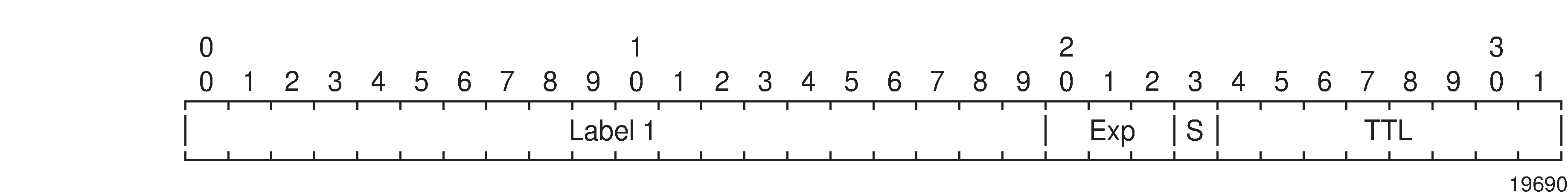
Field |
Description |
|---|---|
Label |
This 20-bit field carries the actual value (unstructured) of the label. |
Exp |
This 3-bit field is reserved for experimental use. It is currently used for Class of Service (CoS). |
S |
This bit is set to 1 for the last entry (bottom) in the label stack and 0 for all other label stack entries. |
TTL |
This 8-bit field is used to encode a time-to-live value. |
A stack can carry several labels, organized in a last in/first out order. The top of the label stack appears first in the packet and the bottom of the stack appears last (Label Packet Placement).

The label value at the top of the stack is looked up when a labeled packet is received. A successful lookup reveals:
the next hop where the packet is to be forwarded
the operation to be performed on the label stack before forwarding
In addition, the lookup may reveal outgoing data link encapsulation and other information needed to properly forward the packet.
An empty label stack can be thought of as an unlabeled packet. An empty label stack has zero (0) depth. The label at the bottom of the stack is referred to as the Level 1 label. The label above it (if it exists) is the Level 2 label, and so on. The label at the top of the stack is referred to as the Level m label.
Label Values
The 7705 SAR uses RSVP-TE and LDP protocols for label forwarding, For packet-based services such as VLL, the 7705 SAR uses T-LDP for signaling PW labels between peer nodes.
Packets traveling along an LSP are identified by the packet label, which is the 20-bit, unsigned integer (see Label Edge and Label Switch Routers). The range is 0 through 1 048 575. Label values 0 to 15 are reserved and are defined below:
A value of 0 represents the IPv4 Explicit NULL label. This label value is legal only at the bottom of the label stack if the label stack is immediately followed by an IPv4 header, in which case the packet forwarding is based on the IPv4 header. If the IPv4 Explicit NULL label is not at the bottom of the label stack, then the packet forwarding is based on the subsequent label.
A value of 1 represents the router alert label. This label value is legal anywhere in the label stack except at the bottom. When a received packet contains this label value at the top of the label stack, it is delivered to a local software module for processing. The actual packet forwarding is determined by the label beneath it in the stack. However, if the packet is further forwarded, the router alert label should be pushed back onto the label stack before forwarding. The use of this label is analogous to the use of the router alert option in IP packets. Since this label cannot be at the bottom of the stack, it is not associated with a particular network layer protocol.
A value of 3 represents the Implicit NULL label. An LER advertises this when it is requesting penultimate hop popping (PHP) and expecting unlabeled packets. The label value 3 should never appear in the label stack.
A value of 7 represents the entropy label indicator (ELI). The ELI is a special-purpose MPLS label that indicates that the entropy label (EL) follows it in the stack.
Values 4 through 6 and 8 through 15 are reserved for future use.
Ingress Label Values (Pop Labels) lists the label ranges available for use by ingress labels (pop labels).
Label Values |
Description |
|---|---|
16 through 31 |
Reserved for future use |
32 through 1023 |
Available for static outer LSP tunnel label assignment |
1024 through 2047 |
Reserved for future use |
|
2048 through 18 4311 |
Statically assigned for services (inner pseudowire label) |
32 768 through 131 071 |
Dynamically assigned for both MPLS and services |
131 072 through 1 048 575 |
Reserved for future use |
- In addition, users can define part of the dynamic label range from 18 432 to 131 071 to be the range of labels for the segment routing global block (SRBG).
Egress Label Values (Push Labels) lists the label ranges available for use by egress labels (push labels).
Label Values |
Description |
|---|---|
16 through 1 048 575 |
Can be used for static LSP tunnel and static PW labels |
16 through 1 048 575 |
Can be dynamically assigned for both MPLS tunnel labels and PW labels |
MPLS Entropy Labels
This section contains information about the following topics:
Overview of Entropy Labels
The 7705 SAR supports MPLS entropy labels on RSVP-TE and SR-TE LSPs, as per RFC 6790. The entropy label provides greater granularity for load balancing on an LSR where load balancing is typically based on the MPLS label stack.
The ability of a node to receive and process an entropy label for an LSP is signaled using capability signaling (referred to as entropy label capability (ELC)). Entropy labels are supported on RSVP-TE and SR-TE tunnels.
Inserting an entropy label adds two labels in the MPLS label stack: the entropy label itself and the entropy label indicator (ELI).
The entropy label is inserted directly below the tunnel label and closest to the service payload that has advertised entropy label capability (which may be above the bottom of the stack). The value of the entropy label is calculated at the iLER and is based on a hash of the packet payload header content and other system parameters at ingress. For more information about hashing inputs, see the ‟Per-Flow Hashing” section in the 7705 SAR Interface Configuration Guide.
The ELI is inserted by the iLER. The ELI is a special-purpose MPLS label (value = 7) that indicates that the entropy label is the next label in the stack.
Entropy label capability is advertised at the tunnel level by the far-end node (eLER). This capability can be advertised for an RSVP-TE FEC or an SR-TE tunnel on IS-IS or OSPF. Capability signaling is not supported for point-to-multipoint LSPs, BGP tunnels, or LDP FECs. An LSR used for RSVP-TE and SR-TE tunnels will pass the entropy label capability signal from the downstream LSP segment to upstream peers. However, earlier releases that do not support entropy label functionality will pass the capability flag transparently, without altering the value.
The insertion of an entropy label by the upstream LER on a tunnel enabled for entropy label capability is enabled on a per-service basis. The entropy label is only inserted if the downstream peer has signaled entropy label support. The upstream LER only inserts a single entropy label, even if multiple LSP labels exist in a label stack.
The 7705 SAR supports the entropy label feature for the following services:
Cpipe, Epipe, and Ipipe access to spoke SDP
Cpipe, Epipe, and Ipipe spoke SDP to spoke SDP (vc-switching)
VPLS SAP to VPLS spoke SDP or mesh SDP
VPLS spoke SDP to VPLS spoke SDP
VPRN for RSVP-TE
R-VPLS
IGP shortcut
IS-IS for SR-TE
OSPF for SR-TE
Entropy label capability on RSVP-TE LSPs is enabled on the eLER using the config>router>rsvp>entropy-label-capability command.
At the iLER, the insertion of the entropy label into the label stack is enabled using the entropy-label command under the service, mesh SDP, or spoke SDP context or under the config>router>isis (or ospf)>segment-routing context for SR-TE LSPs.
The entropy label requires the insertion of two additional labels in the label stack. In some cases, this may result in an unsupported label stack depth or large changes in the label stack depth during the lifetime of an LSP (for example, due to switching from a primary path with entropy label capability enabled to a secondary path for which the far end has not signaled entropy label capability).
The entropy-label command under the config>router>mpls and config>router>mpls>lsp contexts provides local control at the head end of an LSP over whether the entropy label is inserted on an LSP by overriding the entropy label capability signaled from the far-end LER, and control over how the additional label stack depth is accounted for. This allows the user to avoid entropy label insertion where there is a risk of the label stack depth becoming too great.
For entropy labels that are supported on LDP tunnels with remote-LFA protection (that is, for rsvp-shortcut), only loop-free alternate protect (lfa-protect) and LFA (lfa-only) are allowed.
Support of entropy labels over RSVP-TE and SR-TE tunnels are the only valid options, except when the 7705 SAR is the LER node with BGP labeled unicast (BGP-LU) tunnels. A 7705 SAR in an LER role can push and pop an entropy label for Epipe and VPLS services with a BGP-LU tunnel riding over an RSVP-TE LSP. Conversely, a 7705 SAR does not support being in an ABR or ASBR role with BGP-LU. Summary of Entropy Label Support lists entropy label support on the 7705 SAR.
Service |
RSVP-TE |
SR-TE |
|---|---|---|
Epipe |
Yes |
Yes |
Ipipe |
Yes |
Yes |
Cpipe |
Yes |
Yes |
Apipe, Fpipe, Hpipe |
No |
No |
VPRN (MP-BGP) |
Yes |
Yes |
VPRN (Layer 3 spoke SDP) |
Yes |
Yes |
IES (Layer 3 spoke SDP) |
Yes |
Yes |
VPLS SDP (spoke/mesh SDP) |
Yes |
Yes |
LDP over IGP shortcut (RSVP) |
Yes |
N/A |
IGP shortcut (SR) |
N/A |
No |
LDP FRR over RSVP |
Yes |
N/A |
LDP stitching over SR (SR to LDP) |
N/A |
Yes1 |
LDP stitching over SR (LDP to SR) |
No |
No |
|
BGP LU 2 |
Yes |
Yes |
SR |
No |
Yes |
EVPN VPLS |
Yes |
Yes |
EVPN Epipe |
Yes |
Yes |
R-VPLS |
Yes |
Yes |
IGP shortcut |
Yes |
No |
SR FRR over TI-LFA or R-LFA |
N/A |
Yes |
Static route with tunnel next hop |
Yes |
Yes |
- On the SR segment because the SR head end injects the entropy label.
- For services that support entropy label.
Inserting and Processing the Entropy Label
This section contains inserting and processing information about the following node types:
Ingress LER
The procedures at the iLER are as specified in section 4.2 of RFC 6790. In general, the router inserts an entropy label into the label stack if the downstream node for the LSP tunnel has signaled support for entropy label and the entropy label is enabled for the particular service.
RFC 6790 specifies that the iLER can insert several entropy labels in the label stack where the LSP hierarchy exists, one for each LSP in the hierarchy. However, this could result in unreasonably large label stacks. Therefore, when there are multiple LSPs in a hierarchy (for example, LDP over RSVP-TE), the router only inserts a single EL/ELI pair within the innermost LSP label closest to the service payload that has advertised entropy label capability.
The router inserts an entropy label on a tunnel that is entropy label-capable when the service has entropy label enabled, even if an implicit or explicit NULL label has been signaled by the downstream LSR or LER. This ensures consistent behavior and ensures that the entropy label value as determined by the iLER is maintained where a tunnel with an implicit NULL label is stitched at a downstream LSR.
LSR
If an LSR is configured for load balancing and an entropy label is found in the label stack, the LSR will take the entropy label into account in the hashing algorithm as follows:
label-only: the entropy label is used as input to the hash routine and the rest of the label stack is ignored.
label-ip: the entropy label and the IP packet are used as input to the hash routine and the rest of the label stack is ignored.
If penultimate hop popping (PHP) has been requested by a next-hop LER, the LSR will retain any entropy label found immediately below the tunnel label that is to be popped. The system will retain and use the entropy label information as input to the local hash routine if an applicable LSR load-balancing mode has been configured.
For more information about LSR load balancing, see the LSR Hashing section in the 7705 SAR Interface Configuration Guide.
Egress LER
At an eLER, if an ELI and entropy label are detected in the label stack, both the ELI and entropy label are popped and the packet processed as normal. This occurs whether or not the system has signaled entropy label capability.
If an ELI is popped that has the bottom of stack (BoS) bit set, the system will discard the packet.
Entropy Label on OAM Packets
Service OAM packets also include an entropy label and ELI if entropy label capability is signaled for the corresponding tunnel and entropy label is enabled for the service. The EL/ELI pair is inserted at the same level in the label stack as it is in user data packets; that is, within the innermost LSP label context closest to the service payload that has advertised entropy label capability. The EL/ELI pair will therefore always reside at a different level in the label stack from special-purpose labels related to the service payload (for example, the router alert label).
OAM packets at the LSP level, such as LSP ping and LSP trace, do not have the EL/ELI pair inserted.
Segment Routing Entropy Label and IPSec, ESPI Hashing, and NGE
Segment routing with entropy label can be used with IPSec and NGE services and with ESPI hashing, as listed below:
IPSec and segment routing entropy label
IPSec over BGP 3107 over segment routing with entropy label
IPSec over static route over segment routing with entropy label
VLL over GRE over IPSec over BGP 3107 over segment routing with entropy label
VLL over GRE over IPSec over static route over segment routing with entropy label
ESPI hashing GRT/VPRN
NGE
VLL, VPLS, and VPRN NGE interaction with entropy label
Entropy Label Configuration
Entropy Label and Load Balancing illustrates the use of entropy labels at the service level.
The iLER has entropy label enabled under an applicable service context and the eLER has entropy label capability enabled. The iLER inserts the ELI and the EL into the label stack. The entropy label value is based on the service ID for point-to-point Layer 2 services.
At the LSR, if hashing is enabled, the LSR recognizes the ELI and uses the entropy label value as the hash result. If the entropy-label command had been disabled at the iLER, the LSR would not find the ELI and would default to hashing based on the label stack, if applicable.
At the ingress LER:
config>service>cpipe>spoke-sdp>entropy-label
config>service>epipe>spoke-sdp>entropy-label
config>service>ipipe>spoke-sdp>entropy-label
config>service>vpls>spoke-sdp>entropy-label
config>service>vpls>mesh-sdp>entropy-label
config>service>vprn>entropy-label
config>service>vprn>interface>spoke-sdp>entropy-label
config>router>isis>segment-routing>entropy-label
config>router>ospf>segment-routing>entropy-label
At the egress LER:
config>router>entropy-label
config>router>rsvp>entropy-label-capability
config>router>mpls>lsp>entropy-label
config>router>isis>entropy-label>override-tunnel-elc
config>router>ospf>entropy-label>override-tunnel-elc
The per-service-hashing command and the l4-load-balancing, teid-load-balancing, and spi-load-balancing commands are mutually exclusive.
For IP traffic, use the l4-load-balancing command. For IP traffic with mobile payload, use the teid-load-balancing and/or the spi-load-balancing command.
Label Edge and Label Switch Routers
A 7705 SAR performs different functions based on its position in an LSP—ingress, egress, or transit—as described in the following list:
ingress Label Edge Router (iLER) — The router at the beginning of an LSP is the iLER. The ingress router encapsulates packets with an MPLS header and forwards the packets to the next router along the path. An LSP can only have one ingress router.
Label Switching Router (LSR) — An LSR can be any intermediate router in the LSP between the ingress and egress routers, swapping the incoming label with the outgoing MPLS label and forwarding the MPLS packets it receives to the next router in the LSP. An LSP can have 0 to 253 transit routers.
egress Label Edge Router (eLER) — The router at the end of an LSP is the eLER. The egress router strips the MPLS encapsulation, which changes it from an MPLS packet to a data packet, and then forwards the packet to its final destination using information in the forwarding table. An LSP can have only one egress router. The ingress and egress routers in an LSP cannot be the same router.
A router in a network can act as an ingress, egress, or transit router for one or more LSPs, depending on the network design.
Constrained-path LSPs are signaled and are confined to one Interior Gateway Protocol (IGP) area. These LSPs cannot cross an autonomous system (AS) boundary.
Static LSPs can cross AS boundaries. The intermediate hops are manually configured so that the LSP has no dependence on the IGP topology or a local forwarding table.
LSP Types
The following LSP types are supported:
static LSPs — a static LSP specifies a static path. All routers that the LSP traverses must be configured manually with labels. No RSVP-TE or LDP signaling is required. Static LSPs are discussed in this chapter.
signaled LSPs — LSPs are set up using the RSVP-TE or LDP signaling protocol. The signaling protocol allows labels to be assigned from an ingress router to the egress router. Signaling is triggered by the ingress routers. Configuration is required only on the ingress router and is not required on intermediate routers. Signaling also facilitates path selection. RSVP-TE is discussed in this chapter, and LDP is discussed in Label Distribution Protocol.
There are two types of signaled LSP:
explicit-path LSPs — MPLS uses RSVP-TE to set up explicit-path LSPs. The hops within the LSP are configured manually. The intermediate hops must be configured as either strict or loose, meaning that the LSP must take either a direct path from the previous hop router to this router (strict) or can traverse other routers (loose). This enables the user to control how the path is set up. Explicit-path LSPs are similar to static LSPs but require less configuration. See RSVP and RSVP-TE. An explicit path that has not specified any hops will follow the IGP route.
constrained-path LSPs — for constrained-path LSPs, the intermediate hops of the LSP are dynamically assigned. A constrained-path LSP relies on the Constrained Shortest Path First (CSPF) routing algorithm to find a path that satisfies the constraints for the LSP. In turn, CSPF relies on the topology database provided by an extended IGP such as OSPF or IS-IS.
Once the path is found by CSPF, RSVP-TE uses the path to request the LSP setup. CSPF calculates the shortest path based on the constraints provided, such as bandwidth, class of service, and specified hops.
If Fast Reroute (FRR) is configured, the ingress router signals the downstream routers so that each downstream router can preconfigure a detour route for the LSP that will be used if there is a failure on the original LSP. If a downstream router does not support FRR, the request is ignored and the router continues to support the original LSP. This can cause some of the detour routes to fail, but the original LSP is not impacted. For more information about FRR, see RSVP-TE Fast Reroute (FRR).
No bandwidth is reserved for the reroute path. If the user enters a value in the bandwidth parameter in the config>router>mpls>lsp>fast-reroute context, it will have no effect on establishing the backup LSP. The following warning message is displayed:
‟The fast reroute bandwidth command is not supported in this release.”
RSVP and RSVP-TE
The Resource Reservation Protocol (RSVP) is a network control protocol used by a host to request specific qualities of service from the network for particular application data streams or flows. RSVP is also used by routers to deliver quality of service (QoS) requests to all nodes along the paths of the flows and to establish and maintain operational state to provide the requested service. In general, RSVP requests result in resources reserved in each node along the data path.
The Resource Reservation Protocol for Traffic Engineering (RSVP-TE) is an extended version of RSVP for MPLS. RSVP-TE uses traffic engineering extensions to support automatic signaling of LSPs. MPLS uses RSVP-TE to set up traffic-engineered LSPs. See RSVP-TE Extensions for MPLS for more information.
RSVP-TE Overview
RSVP-TE requests resources for simplex (unidirectional) flows. Therefore, RSVP-TE treats a sender as logically distinct from a receiver, although the same application process may act as both a sender and a receiver at the same time. Duplex flows require two LSPs, to carry traffic in each direction.
RSVP-TE is a signaling protocol, not a routing protocol. RSVP-TE operates with unicast and multicast routing protocols. Routing protocols determine where packets are forwarded. RSVP-TE consults local routing tables to relay RSVP-TE messages.
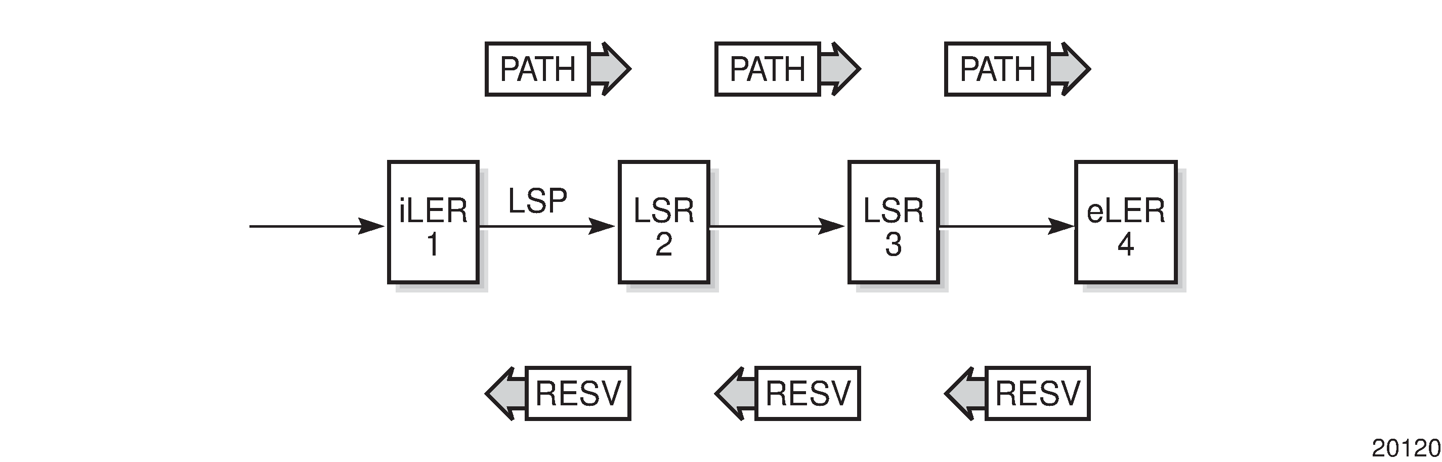
RSVP-TE uses two message types to set up LSPs, PATH and RESV. Establishing LSPs depicts the process to establish an LSP.
The sender (the ingress LER (iLER)) sends PATH messages toward the receiver, (the egress LER (eLER)) to indicate the forwarding equivalence class (FEC) for which label bindings are desired. PATH messages are used to signal and request the label bindings required to establish the LSP from ingress to egress. Each router along the path observes the traffic type.
PATH messages facilitate the routers along the path to make the necessary bandwidth reservations and distribute the label binding to the router upstream.
The eLER sends label binding information in the RESV messages in response to PATH messages received.
The LSP is considered operational when the iLER receives the label binding information.
LSP Using RSVP-TE Path Setup displays an example of an LSP path set up using RSVP-TE. The ingress label edge router (iLER 1) transmits an RSVP-TE PATH message (path: 30.30.30.1) downstream to the egress label edge router (eLER 4). The PATH message contains a label request object that requests intermediate LSRs and the eLER to provide a label binding for this path.
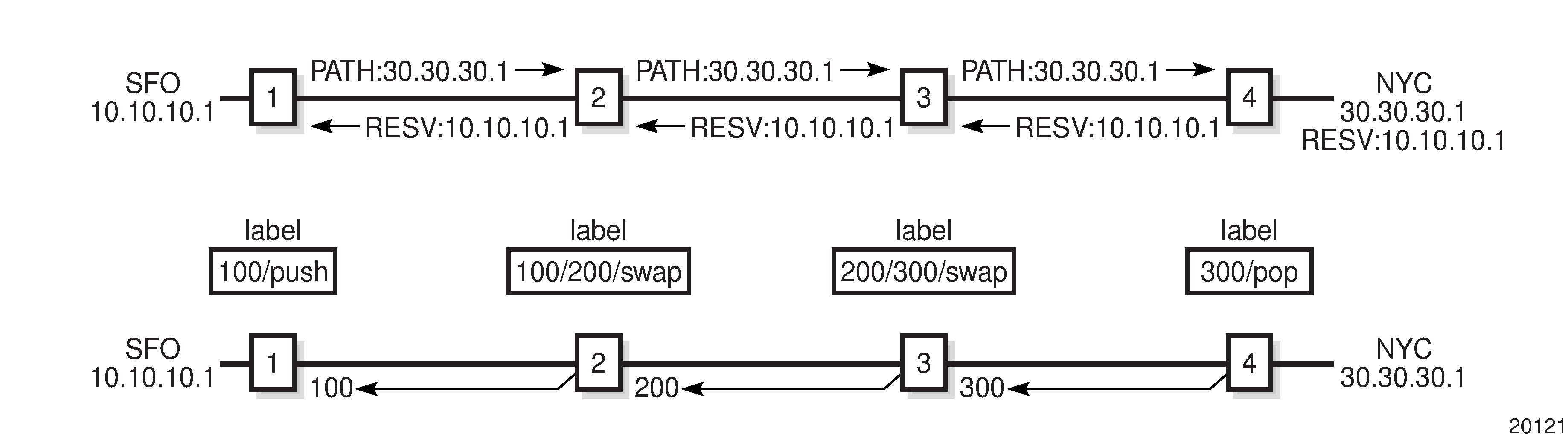
In addition to the label request object, an RSVP-TE PATH message can also contain a number of optional objects:
explicit route object (ERO) — forces the RSVP-TE PATH message to follow the path specified by the ERO (independent of the IGP shortest path)
record route object (RRO) — allows the iLER to receive a listing of the LSRs that the LSP tunnel actually traverses
session attribute object — controls the path setup priority, holding priority, and local rerouting features
Upon receiving a PATH message containing a label request object, the eLER transmits an RESV message that contains a label object. The label object contains the label binding that the downstream LSR communicates to its upstream neighbor. The RESV message is sent upstream towards the iLER, in a direction opposite to that followed by the PATH message. Each LSR that processes the RESV message carrying a label object uses the received label for outgoing traffic associated with the specific LSP. When the RESV message arrives at the ingress LSR, the LSP is established.
Using RSVP-TE for MPLS
Hosts and routers that support both MPLS and RSVP-TE can associate labels with RSVP-TE flows. When MPLS and RSVP-TE are combined, the definition of a flow can be made more flexible. Once an LSP is established, the traffic through the path is defined by the label applied at the ingress node of the LSP. The mapping of label to traffic can be accomplished using a variety of criteria. The set of packets that are assigned the same label value by a specific node are considered to belong to the same Forwarding Equivalence Class (FEC) that defines the RSVP-TE flow.
For use with MPLS, RSVP-TE already has the resource reservation component built in, making it ideal to reserve resources for LSPs.
RSVP-TE Extensions for MPLS
The RSVP-TE extensions enable MPLS to support the creation of explicitly routed LSPs, with or without resource reservation. Several of the features enabled by these extensions were implemented to meet the requirements for traffic engineering over MPLS, which enables the creation of traffic trunks with specific characteristics. None of the TE extensions result in backward compatibility problems with traditional RSVP implementations.
To run properly, the traffic engineering capabilities of RSVP-TE require an underlying TE-enabled IGP routing protocol. The 7705 SAR supports OSPF and IS-IS with TE extensions.
Routing protocols make it possible to advertise the constraints imposed over various links in the network. For example, in order for the nodes in a network to choose the best link for signaling a tunnel, the capacity of a particular link and the amount of reservable capacity must be advertised by the IGP. RSVP-TE makes use of these constraints to request the setup of a path or LSP that traverses only those links that are part of an administrative group (admin groups are described in the following list). Therefore, both RSVP-TE and the IGP-TE (that is, OSPF-TE or IS-IS-TE for the 7705 SAR) must be enabled and running simultaneously.
The following TE capabilities are supported:
hop limit — the hop limit is the maximum number of LSRs that a given LSP can traverse, including the ingress and the egress LERs. Typically, the hop limit is used to control the maximum delay time for mission-critical traffic such as voice traffic.
The hop limit applies to the primary LSP, any backup LSPs, and LSPs configured to be used in Fast Reroute (FRR) situations.
admin groups — administrative groups provide a way to define which LSR nodes should be included or excluded while signaling an LSP. For example, it might be desirable to avoid some nodes or links that are known to be used heavily from being included in the path of an LSP, or to include a specific LSR node to ensure that a newly signaled RSVP-TE tunnel traverses that LSR node.
Administrative groups apply to both primary and secondary LSPs. They are defined under the config>router>if-attribute context, and are applied at the MPLS interface level, as well as at the LSP and the primary and secondary LSP levels through include and exclude commands.
bandwidth — the bandwidth capability (supported by RSVP-TE), is similar to the Connection Admission Control (CAC) function in ATM. During the establishment phase of RSVP-TE, the LSP PATH message contains the bandwidth reservation request. If the requested capacity is available, the RESV message confirms the reservation request. The amount of reserved bandwidth stated in the request is deducted from the amount of reservable bandwidth for each link over which the LSP traverses.
The bandwidth capability applies to both primary and secondary LSPs, and LSPs configured to be used in Fast Reroute (FRR) situations.
Hello Protocol
The Hello protocol detects the loss of a neighbor node (node failure detection) or the reset of a neighbor’s RSVP-TE state information. In standard RSVP, neighbor monitoring occurs as part of the RSVP soft-state model. The reservation state is maintained as cached information that is first installed and then periodically refreshed by the ingress and egress LERs. If the state is not refreshed within a specified time interval, the LSR discards the state because it assumes that either the neighbor node has been lost or its RSVP-TE state information has been reset.
The Hello protocol extension is composed of a Hello message, a Hello request object and a Hello ACK object. Hello processing between two neighbors supports independent selection of failure detection intervals. Each neighbor can automatically issue Hello request objects. Each Hello request object is answered by a Hello ACK object.
Authentication
Protocol authentication protects against malicious attacks on the communications between routing protocol neighbors. These attacks could either disrupt communications or inject incorrect routing information into the systems routing table. The use of authentication keys can help to protect routing protocols from these types of attacks.
All RSVP-TE protocol exchanges can be authenticated. This guarantees that only trusted routers can participate in autonomous system routing.
Authentication must be explicitly configured and can be done using two separate mechanisms:
configuration of an explicit authentication key and algorithm using the authentication-key command
configuration of an authentication keychain using the auth-keychain command
Either the authentication-key command or the auth-keychain command can be used by RSVP-TE, but both cannot be supported at the same time. If both commands are configured, the auth-keychain configuration will be applied and the authentication-key command will be ignored.
By default, authentication is not enabled on an interface.
Authentication Key
When enabled on an RSVP-TE interface with the authentication-key command, authentication of RSVP messages operates in both directions of the interface. A node maintains a security association with its neighbors for each authentication key. The following items are stored in the context of this security association:
the HMAC-MD5 authentication algorithm
the key used with the authentication algorithm
the lifetime of the key. A key is a user-generated key using third-party software or hardware. The value is entered as a static string into the CLI configuration of the RSVP interface. The key will continue to be valid until it is removed from that RSVP interface.
the source address of the sending system
the latest sending sequence number used with this key identifier
The RSVP sender transmits an authenticating digest of the RSVP message, computed using the shared authentication key and a keyed hash algorithm. The message digest is included in an Integrity object that also contains a Flags field, a Key Identifier field, and a Sequence Number field. The RSVP sender complies with the procedures for RSVP message generation in RFC 2747, RSVP Cryptographic Authentication.
An RSVP receiver uses the key together with the authentication algorithm to process received RSVP messages.
If a point of local repair (PLR) node switches the path of the LSP to a bypass LSP, it does not send the integrity object in the RSVP messages over the bypass tunnel. If an integrity object is received from the merge point (MP) node, then the message is discarded since there is no security association with the next-next-hop MP node.
The 7705 SAR MD5 implementation does not support the authentication challenge procedures in RFC 2747.
Authentication Keychains
The keychain mechanism allows for the creation of keys used to authenticate RSVP-TE communications. Each keychain entry defines the authentication attributes to be used in authenticating RSVP-TE messages from remote peers or neighbors; the entry must include at least one key entry to be valid. The keychain mechanism also allows authentication keys to be changed without affecting the state of the RSVP-TE adjacencies and supports stronger authentication algorithms than plaintext and MD5.
Keychains are configured in the config>system>security>keychain context. For more information about configuring keychains, see the 7705 SAR System Management Guide, ‟TCP Enhanced Authentication and Keychain Authentication”.
The keychain is then associated with an RSVP-TE interface with the auth-keychain command.
For a key entry to be valid, it must include a valid key, the current system clock value must be within the begin and end time of the key entry, and the algorithm specified must be supported by RSVP-TE.
RSVP-TE supports the following authentication algorithms:
HMAC-MD5
HMAC-SHA-1-96
HMAC-SHA-1
HMAC-SHA-256
Keychain errors are handled as follows.
If a keychain exists but there are no active key entries with an authentication type that matches the type supported by RSVP-TE, inbound RSVP-TE packets will not be authenticated and will be discarded and no outbound RSVP-TE packets will be sent.
If a keychain exists but the last key entry has expired, a log entry will be raised indicating that all keychain entries have expired.
RSVP-TE requires that the protocol continue to authenticate inbound and outbound traffic using the last valid authentication key.
Non-Router ID Addresses as Destinations and Hops
The address of a configured loopback interface, other than the router ID, can be used as the destination of an RSVP LSP. For a constrained-path LSP, CSPF searches for the best path that matches the constraints across all areas or levels of the IGP where this address is reachable. If the address is the router ID of the destination node, then CSPF selects the best path across all areas or levels of the IGP for that router ID, regardless of which area or level the router ID is reachable for as an interface.
The address of a loopback interface other than the router ID can also be configured as a hop in the LSP path hop definition. If the hop is ‟strict” and corresponds to the router ID of the node, the CSPF path may use any TE-enabled link to the downstream node based on best cost. If the hop is ‟strict” and does not correspond to the router ID of the node, CSPF will fail.
RSVP LSP and LDP FEC Statistics
RSVP LSP and LDP FEC statistics allow operators to monitor traffic being forwarded between any two PE routers and for all services using an RSVP or LDP SDP. If the LSP is used as a shortcut to transport BGP LU, VPRN traffic over MP-BGP or IGP prefixes, statistics are collected for these IP packets being forwarded.
The following statistics are collected for each RSVP LSP or LDP FEC:
per forwarding class forwarded in-profile packet count
per forwarding class forwarded in-profile byte count
per forwarding class forwarded out-of-profile packet count
per forwarding class forwarded out-of-profile byte count
For an RSVP LSP, these counters are available for the egress data path at the ingress LER and for the ingress data path at the egress LER.
For an LDP FEC, these counters are available for the egress data path at the ingress LER and LSR. Because an ingress LER is also potentially an LSR for an LDP FEC, combined egress data path statistics are provided whenever applicable.
OAM packets that are forwarded using LSP encapsulation, such as LSP ping and LSP trace, are also included in the above counters.
Dropped packets and bytes for an RSVP LSP or LDP FEC are not counted on the ingress LER.
Octet counters are for the entire frame and include the label stack and Layer 2 header and padding, similar to existing MPLS interface counters. For that reason, ingress and egress octet counters for an RSVP LSP may differ slightly if the type of interface or encapsulation is different (POS, Ethernet null, or Ethernet dot1q).
RSVP LSP and LDP FEC statistics counters can be retrieved by:
using the CLI show command for the RSVP LSP or the LDP FEC
using the CLI monitor command applied to a specific RSVP LSP or LDP FEC
using an SNMPv3 interface to query the MIB
accessing an accounting file if statistics collection is enabled with the default or a user-specified accounting policy for the RSVP LSP or LDP FEC
RSVP LSP and LDP FEC statistics counters are not saved to an accounting file unless statistics collection is enabled and the specific RSVP LSP or LDP FEC statistics collection record is included in the default accounting policy or in a user-defined accounting policy using the following commands:
RSVP LSP ingress data path counters
config>router>mpls>ingress-statistics>lsp>collect-stats
config>router>mpls>ingress-statistics>lsp>accounting-policy policy-id
RSVP LSP egress data path counters
config>router>mpls>lsp>egress-statistics>collect-stats
config>router>mpls>lsp>egress-statistics>accounting-policy policy-id
LDP FEC egress data path counters
config>router>ldp>egress-statistics>fec-prefix>collect-stats
config>router>ldp>egress-statistics>fec-prefix>accounting-policy policy-id
Configuring RSVP LSP Statistics at Ingress LER
At the ingress LER, statistics are configured in the egress data path of an originating LSP with the config>router>mpls>lsp>egress-statistics command in the LSP configuration at the head-end node. Statistics collection in the egress data path is enabled after the user executes the no shutdown command in the egress-statistics context. By default, this function is in a shutdown state.
Statistics cannot be configured if the LSP name contains a colon (:), which is used as a field separator by the ingress LER for encoding the LSP and path names into the RSVP Session Name field in the Session_Attribute object.
The no form of the egress-statistics command disables statistics collection in the egress data path and removes the accounting policy association from the RSVP LSP. Users can choose to disable statistics in the egress data path while keeping the accounting policy association of the RSVP LSP with the config>router>mpls>lsp>egress-statistics shutdown command.
The same set of counters are updated for packets forwarded over any path of the LSP. In the steady state, counters are updated for packets forwarded over the active path of the LSP. The active path can be the primary path, one of the secondary paths, the FRR detour path, or the FRR bypass path when the head-end node is also the PLR.
The LSP counters are maintained over the lifetime of the LSP as long as statistics are enabled. The user can clear the counters with the clear>router>mpls>lsp-egress-stats [lsp-name] command.
LSP statistics are not collected on a dynamic or static bypass tunnel. LSP egress statistics are also not collected if the head-end node is also the penultimate-popping hop (PHP) node for a single-hop LSP using an implicit null label. However, if any label is pushed onto the label stack, for example, the Layer 2 or Layer 3 service label, the egress statistics are counted for the LSP even if the transport MPLS label is not present.
When a hierarchy of LSPs is in use, statistics collection on the outermost label corresponding to the tunneling LSP and on the inner labels, corresponding to the tunneled LSPs, are mutually exclusive. The outermost label takes precedence. Consequently, when the user enables statistics collection on an RSVP LSP that is also used for tunneling LDP FECs with the LDP over RSVP shortcut, statistics will be collected on the RSVP LSP only. No statistics are collected for an LDP FEC tunneled over this RSVP LSP even if the user enabled statistics collection on the FEC. When the user disables statistics collection on the RSVP LSP, statistics collection, if enabled, will be performed on the tunneled LDP FEC.
LSP statistics are not collected on static LSPs. Auto-LSP templates do not support LSP statistics collection.
Configuring RSVP LSP Statistics at Egress LER
At the egress LER, statistics are configured in the ingress data path of a terminating LSP by entering the LSP name, along with the ingress LER system interface address, with the config>router>mpls>ingress-statistics>lsp lsp-name sender ip-address command. Statistics collection is enabled in the ingress data path after the user executes the no shutdown command in the ingress-statistics context. By default, this function is in a shutdown state.
The LSP name must correspond to the name configured by the user at the ingress LER. Statistics cannot be configured if the LSP name contains a colon (:), which is used as a field separator by the ingress LER for encoding the LSP and path names into the RSVP Session Name field in the Session_Attribute object.
The no form of the ingress-statistics command disables statistics collection in the ingress data path and removes the accounting policy association from the RSVP LSP. Users can choose to disable statistics in the ingress data path while keeping the accounting policy association of the RSVP LSP with the config>router>mpls>ingress-statistics>lsp>shutdown command.
The same set of counters are updated for packets received over any path of the LSP. In the steady state, the counters are updated for packets received over the active path of the LSP. The active path can be the primary path, one of the secondary paths, the FRR detour path, or the FRR bypass path when the tail-end node is also the MP.
The LSP counters are maintained over the lifetime of the LSP as long as statistics are enabled. The user can clear the counters with the clear>router>mpls>lsp-ingress-stats ip-address lsp lsp-name command.
When a hierarchy of LSPs is in use, statistics collection on the outermost label corresponding to the tunneling LSP and on the inner labels, corresponding to the tunneled LSPs, are mutually exclusive. The outermost label takes precedence.
Because ingress data path statistics are not supported for an LDP FEC, there are no statistics collected for an LDP FEC, however if the LDP FEC is tunneled over an RSVP shortcut LSP that has LSP ingress statistics configured, the statistics are collected for the RSVP LSP
The user can enable statistics collection on a manual bypass LSP terminating on the egress LER. However, all LSPs whose primary path is protected by the manual bypass will not collect statistics when they activate forwarding over the manual bypass. If the user disables statistics collection on the manual bypass LSP, statistics collection, if enabled, is continued on the protected LSP when the bypass LSP is activated.
A flag in the output of the show command for the LSP statistics will indicate if there were no path state blocks (PSBs) that matched the specified LSP name at any given point in time. This could be due to the absence of the RSVP session or to the presence of a session type that is not supported; for example, the LSP name matched a point-to-multipoint LSP. The counters will show all zero values, which could otherwise be confused with an LSP with a valid matched PSB that is not receiving packets.
Configuring LDP FEC Statistics
At the ingress LER and LSR, statistics collection is configured in the egress data path of an LDP FEC by specifying the FEC prefix with the config>router>ldp>egress-statistics>fec-prefix command. Statistics collection is enabled in the egress data path after the user executes the no shutdown command under the egress-statistics context. By default, this function is in a shutdown state.
The no form of the egress-statistics command disables statistics collection in the egress data path and removes the accounting policy association from the LDP FEC. Users can choose to disable statistics in the egress data path while keeping the accounting policy association of the LDP FEC with the config>router>ldp>egress-statistics>fec-prefix>shutdown command.
Statistics collection applies to prefix FECs imported from both LDP neighbors and T-LDP neighbors.
The egress data path counters are updated for both originating and transit packets. Originating packets may be service packets or IP user and control packets forwarded either as BGP LU over LDP FEC or as VPRN traffic (MP-BGP) over LDP FEC or simply over LDP FEC IGP shortcut. Transit packets of the FEC are label-switched on this node.
When ECMP is enabled and multiple paths exist for a FEC, the same set of counters is updated for each packet forwarded over any of the ECMP links for as long as this FEC is active.
The LDP FEC counters are maintained over the lifetime of the FEC as long as statistics are enabled. The user can clear the counters with the clear>router>ldp>fec-egress-statistics command.
For more information about LDP FEC statistics commands, see LDP Commands.
RSVP-TE Signaling
RSVP-TE-based signaling provides a means to establish tunnels dynamically.
RSVP-TE uses the Downstream on Demand (DOD) label distribution mode, sending PATH messages from the ingress LER node to the egress LER and RESV messages in the reverse direction. DOD label distribution is a router’s response to an explicit request from another router for label binding information. The DOD mode is in contrast to LDP on the 7705 SAR, which uses the Downstream Unsolicited (DU) label distribution mode for both PWs and LSPs. A router in DU mode will distribute label bindings to another router that has not explicitly requested the label bindings.
RSVP-TE signaling is supported when the 7705 SAR is deployed as an LER and as an LSR. When used as an LER, the 7705 SAR uses RSVP-TE signaling to set up constrained paths because only the LER knows all the constraints imposed on the LSP. When used as an LSR, the 7705 SAR uses RSVP-TE to interpret the RSVP-TE messages (including all the constraints).
With RSVP-TE, users can choose which services and PWs may use a particular LSP. One-to-one or many-to-one scenarios for binding PWs to RSVP-TE LSPs is supported, which is similar to binding PWs to static LSPs. Furthermore, each RSVP-TE LSP can be configured with its own set of attributes and constraints.
General Attributes of RSVP-TE
The following general attributes of RSVP-TE on the 7705 SAR are supported:
Bidirectional Forwarding Detection
Bidirectional Forwarding Detection (BFD) is supported on the 7705 SAR. In the case of BFD for RSVP-TE, an RSVP-TE enabled link is registered with the BFD state machine, and if a failure occurs the RSVP-TE interface is taken out of service. The BFD implementation on the 7705 SAR works on a hop-by-hop basis, and if BFD detects a link failure, only the two directly connected MPLS nodes are aware of that failure. If the node that detects the link failure is an LSR node, it generates PATH-ERR messages to the originators (the LER nodes) of the failing LSPs. If FRR is configured, the detecting node takes corrective action itself. See LSP Redundancy and RSVP-TE Fast Reroute (FRR) for more information about these topics.
Timers
The following timers are implemented to ensure the successful operation of RSVP-TE:
bypass-resignal-timer — the bypass resignal timer defines the time between the global reoptimization of all dynamic bypass RSVP-TE LSPs. For more information, see Bypass Resignal Timer.
hold-timer — the hold timer defines the amount of time before an LSP is brought up and is in service, which provides protection against unreliable nodes and links
resignal-timer — the resignal timer is used in conjunction with the route optimization process, especially after a reroute has occurred. If the newly computed path for an LSP has a better metric than the currently recorded hop list, an attempt is made to resignal that LSP, and if the attempt is successful, a make-before-break switchover occurs. If the attempt to resignal an LSP fails, the LSP continues to use the existing path and another resignal attempt is made the next time the timer expires.
When the resignal timer expires, a trap and syslog message are generated.
retry-timer — the retry timer defines a period of time before a resignal attempt is made after an LSP failure. This delay time protects network resources against excessive signaling overhead.
LSP Resignal Limit
When an LSP fails, an LER node tries to resignal it. The following limit can be configured:
retry-limit — the retry limit defines the number of resignaling attempts in order to conserve the resources of the nodes in the network. There could be a serious loss of capacity due to a link failure where an infinite number of retries generate unnecessary message overhead.
RSVP-TE Message Pacing
RSVP-TE message pacing provides a means to limit the overwhelming number of RSVP-TE signaling messages that can occur in large MPLS networks during node failures. RSVP-TE message pacing allows the messages to be sent in timed intervals.
To protect nodes from receiving too many messages, the following message pacing parameters can be configured:
msg-pacing — message pacing can be enabled or disabled
max-burst — maximum burst defines the number of RSVP-TE messages that can be sent in the specified period of time
period — period defines the interval of time used in conjunction with the max-burst parameter to send message pacing RSVP-TE messages
Message pacing needs to be enabled on all the nodes in a network to ensure the efficient operation of tier-1 nodes. Message pacing affects the number of RSVP-TE messages that a particular node can generate, not the number of messages it can receive. Therefore, each node must be paced at a rate that allows the most loaded MPLS nodes to keep up with the number of messages they receive.
RSVP-TE Overhead Refresh Reduction
RFC 2961, RSVP Refresh Overhead Reduction Extensions, defines enhancements to the RSVP-TE signaling protocol that reduce refresh overhead, which are in addition to the message pacing function.
These extensions are:
-
RSVP-TE message bundling — RSVP-TE message bundling reduces the total number of RSVP-TE messages by aggregating the status information of multiple LSPs into a single RSVP-TE PDU. The 7705 SAR supports the receipt and processing of bundled RSVP-TE messages but not the transmission of bundled messages as specified in RFC 2961, section 3.3.
-
reliable message delivery — reliable message delivery extends RSVP-TE to support MESSAGE_ACK. Each RSVP-TE PDU has a unique message-id for sequence tracking purposes. When an RSVP-TE message arrives, the recipient acknowledges the reception of the specific message-id (this is similar to TCP ACK messages). Lost PDUs can be detected and re-sent with this method, which helps reduce the refresh rate because there are two endpoints tracking the received/lost messages.
-
summary refresh — the summary refresh capability uses a single message-id list to replace many individual refresh messages and sends negative ACKs (NACKs) for any message-id that cannot be matched (verified). The summary refresh capability reduces the number of message exchanges and message processing between peers. It does not reduce the amount of soft state stored in the node. The term soft state refers to the control state in hosts and routers that will expire if not refreshed within a specified amount of time (see RFC 2205 for information about soft state).
These capabilities can be enabled on a per-RSVP-TE interface basis and are referred to collectively as ‟refresh overhead reduction extensions”. When refresh-reduction is enabled on a 7705 SAR RSVP-TE interface, the node indicates this to its peer by setting a refresh-reduction-capable bit in the flags field of the common RSVP-TE header. If both peers of an RSVP-TE interface set this bit, all three of the capabilities listed above can be used. The node monitors the setting of this bit in received RSVP-TE messages from the peer on the interface. If the bit is cleared, the node stops sending summary refresh messages. If a peer did not set the refresh-reduction-capable bit, a 7705 SAR node does not attempt to send summary refresh messages.
Also, reliable delivery of RSVP-TE messages over the RSVP-TE interface can be enabled using the reliable-delivery option.
RSVP-TE Reservation Styles
LSPs can be signaled with explicit reservation styles for the reservation of resources, such as bandwidth. A reservation style describes a set of attributes for a reservation, including the sharing attributes and sender selection attributes. The style information is part of the LSP configuration. The 7705 SAR supports two reservation styles:
fixed filter (FF) — the fixed filter (FF) reservation style specifies an explicit list of senders and a distinct reservation for each of them. Each sender has a dedicated reservation that is not shared with other senders. Each sender is identified by an IP address and a local identification number, the LSP ID. Because each sender has its own reservation, a unique label and a separate LSP can be constructed for each sender-receiver pair. For traditional RSVP applications, the FF reservation style is ideal for a video distribution application in which each channel (or source) requires a separate pipe for each of the individual video streams.
shared explicit (SE) — the shared explicit (SE) reservation style creates a single reservation over a link that is shared by an explicit list of senders. Because each sender is explicitly listed in the RESV message, different labels can be assigned to different sender-receiver pairs, thereby creating separate LSPs.
If the FRR option is enabled for the LSP and the facility FRR method is selected at the head-end node, only the SE reservation style is allowed. If a 7705 SAR PLR node receives a PATH message with fast reroute requested with facility method and the FF reservation style, it will reject the reservation. The one-to-one backup method supports both FF and SE styles.
Implicit Null Label
The implicit null label option enables an eLER to receive MPLS packets from the previous-hop LSR without the outer LSP label.
The implicit null label is included in RESV messages sent by the eLER to the previous-hop LSR. When the implicit null label is signaled to the LSR, it pops the outer label before sending the MPLS packet to the eLER; this is known as penultimate hop popping.
The implicit null label option can be enabled for all RSVP-TE interfaces and for all RSVP-TE LSPs for which the router is the eLER by using the implicit-null-label command in the config>router>rsvp context.
RSVP-TE must be shut down before this command can be used.
The implicit null label option can also be enabled or disabled on a specific RSVP-TE interface, overriding the RSVP-TE level configuration, by using the implicit-null-label {enable | disable} command in the config>router>rsvp>interface context.
The implicit null label is enabled for all LSPs for which the router is the eLER and for which the PATH message is received from the previous-hop LSR over the RSVP-TE interface.
With facility backup, if the eLER is also the merge point (MP) node, the incoming interface for the PATH refresh message over the bypass tunnel dictates whether the packet will use the implicit null label. Similarly, with one-to-one backup, if the eLER is also the detour merge point (DMP) node, the incoming interface for the PATH refresh message over the detour LSP dictates whether the packet will use the implicit null label.
The RSVP-TE interface must be shut down before this command can be used.
RSVP-TE Entropy Labels
The 7705 SAR supports entropy labels as described in MPLS Entropy Labels.
LSP Redundancy
Each primary LSP can be protected by up to two secondary LSPs. When the LER detects a primary LSP failure, it signals its secondary LSPs, if any have been configured, and automatically switches to the first one that is available. LSP redundancy supports shared risk link groups (SRLG). See Shared Risk Link Groups for more information about SRLG.
LSP redundancy differs from the Fast Reroute (FRR) feature in that LSP redundancy is controlled by the LER that initiated the LSP, whereas FRR uses the node that detects the failure to take recovery action. This means that LSP redundancy takes longer to reroute traffic than FRR because failure messages need to traverse multiple hops to reach the LER and activate LSP redundancy, whereas an FRR-configured node responds immediately to bypass the failed node or link. See RSVP-TE Fast Reroute (FRR) for more information on FRR.
The following parameters can be configured for primary and secondary LSPs:
bandwidth — the amount of bandwidth needed for the secondary LSP can be reserved and can be any value; it does not need to be identical to the value reserved by the primary LSP. Bandwidth reservation can be set to 0, which is equivalent to reserving no bandwidth.
inclusion and exclusion of nodes — by including or excluding certain nodes, you can ensure that the primary and secondary LSPs do not traverse the same nodes and therefore ensure successful recovery. Each secondary LSP can have its own list of included and excluded nodes.
hop limit — the hop limit is the maximum number of LSRs that a secondary LSP can traverse, including the ingress and egress LERs.
standby (secondary LSPs only) — when a secondary LSP is configured for standby mode, it is signaled immediately and is ready to take over traffic the moment the LER learns of a primary LSP failure. This mode is also called hot-standby mode.
When a secondary LSP is not in standby mode, then it is only signaled when the primary LSP fails. If there is more than one secondary LSP, they are all signaled at the same time (upon detection of a primary LSP failure) and the first one to come up is used.
If a path-preference priority value is configured for standby secondary LSP paths, the standby secondary LSP configured with the highest path priority becomes the active LSP when the primary LSP fails.
Make-Before-Break (MBB) Procedures for LSP and Path Parameter Configuration Changes
The Make-Before-Break (MBB) procedure allows an LSP to switch from an existing working path to a new path without interrupting service. The MBB procedure does this by first signaling the new path when it is operationally up, having the ingress LER move the traffic to the new path, and then allowing the ingress LER to tear down the original path.
The MBB procedure is invoked during the following operations:
timer-based and manual resignal of an LSP path
Fast Reroute (FRR) global revertive procedures
Traffic Engineering (TE) graceful shutdown procedures
update of the secondary path due to an update to the primary path SRLG
LSP primary or secondary path name change
LSP or path configuration parameter change
MBB procedure coverage has been extended to most of the other LSP-level and path-level parameters as follows:
including or excluding admin groups at the LSP and path levels
enabling or disabling the LSP-level CSPF option
enabling or disabling LSP-level use-te-metric parameters when the CSPF option is enabled
enabling or disabling the LSP-level hop-limit option in the fast-reroute context
enabling the LSP-level least-fill option
enabling or disabling the LSP-level adspec option
changing between node-protect and no node-protect (link-protect) values in the LSP-level fast-reroute option
changing the LSP-level and path-level hop-limit parameter values
enabling or disabling primary or secondary path record or record-label options
The MBB procedure is not supported on a manual bypass LSP.
Automatic Creation of RSVP-TE LSPs
Automatic creation of RSVP-TE LSPs enables the automated creation of point-to-point RSVP-TE LSPs within a single IGP IS-IS level or OSPF area that can subsequently be used by services and/or IGP shortcuts. The feature is divided into two modes: creation of an RSVP-TE LSP mesh, and creation of single-hop RSVP-TE LSPs.
When creating an RSVP-TE LSP mesh, the mesh can be full or partial, the extent of which is governed by a prefix list containing the system addresses of all nodes that should form part of the mesh. When using single-hop RSVP-TE LSPs, point-to-point LSPs are established to all directly connected neighbors.
The use of automatically created RSVP-TE LSPs avoids manual configuration of RSVP-TE LSP meshes. Even when provisioning tools are used to automatically provision these LSPs, automatic creation of a mesh still provides a benefit by avoiding increased configuration file sizes.
Automatic Creation of RSVP-TE LSP Mesh (Auto-LSP)
This feature enables the automatic creation of an RSVP-TE point-to-point LSP to a destination node whose router ID matches a prefix in the specified peer prefix policy. This LSP type is referred to as an auto-created LSP mesh. To start the process of automatically creating an RSVP-TE LSP mesh, the user must create a route policy referencing a prefix list. This prefix list contains the system addresses of all nodes that are required to be in the mesh, and can be entered as a series of /32 addresses, or simply as a range.
After the route policy is created, the user must create an LSP template containing the common parameters that are used to establish all point-to-point LSPs within the mesh. The template must be created with the keyword mesh-p2p:
config>router>mpls>lsp-template template-name mesh-p2p
Upon creation of the template, CSPF is automatically enabled and cannot be disabled. The template must also reference a default path before it can be placed in a no shutdown state.
Next, the user must associate the LSP template with the previously defined route policy, and this is accomplished using the auto-lsp lsp-template command:
config>router>mpls>auto-lsp lsp-template template-name policy peer-prefix-policy
Once the auto-lsp lsp-template command is entered, the system starts the process of establishing the point-to-point LSPs. The prefixes defined in the prefix list are checked, and if a prefix corresponds to a router ID that is present in the Traffic Engineering (TE) database, the system instantiates a CSPF-computed primary path to that prefix using the parameters specified in the LSP template.
Multiple templates can be associated with the same or different peer prefix policies. Each application of an LSP template with a given prefix in the prefix list results in the instantiation of a single CSPF-computed LSP primary path using the LSP template parameters, as long as the prefix corresponds to a router ID for a node in the TE database. Auto LSP does not support the automatic signaling of a secondary path for an LSP. If the signaling of multiple LSPs to the same destination node is required, a separate LSP template must be associated with a prefix list that contains the same destination node address. Each instantiated LSP will have a unique LSP ID and a unique tunnel ID.
The auto-created LSP is installed in the Tunnel Table Manager (TTM) and is available to applications such as resolution of BGP label routes, and resolution of BGP, IGP, and static routes. The auto-created LSP can also be used for auto-binding by a VPRN service. The auto-created LSP cannot be used as a provisioned SDP for explicit binding by services.
The auto-created LSP mesh can be signaled over both numbered and unnumbered RSVP-TE interfaces.
Up to five peer prefix policies can be associated with an LSP template. Every time the user executes the auto-lsp command with the same or different prefix policy associations or changes the prefix policy associated with an LSP template, the system re-evaluates the prefix policy. The outcome of the re-evaluation indicates to MPLS whether an existing LSP must be torn down or a new LSP must be signaled to a destination address that is already in the TE database.
If a /32 prefix is added to or removed from a prefix list associated with an LSP template, or if a prefix range is expanded or narrowed, the prefix policy re-evaluation is performed. Whether the prefix list contains one or more specific /32 addresses or a range of addresses, MPLS requires an external trigger to instantiate an LSP to a node whose address matches an entry in the prefix list. The external trigger is when the router with a router ID matching an address in the prefix list appears in the TE database. The TE database provides the trigger to MPLS.
The user must perform a no shutdown of the template before it takes effect. When a template is in use, the user must shut down the template before changing any parameters except for those LSP parameters for which the change can be handled with the Make-Before-Break (MBB) procedures (see Make-Before-Break (MBB) Procedures for LSP and Path Parameter Configuration Changes). When the template is shut down and parameters are added, removed, or modified, the existing instances of the LSP using this template are torn down and resignaled.
MBB procedures for manual and timer-based resignaling of the LSP, and for TE graceful shutdown, are supported.
The tools>perform>router>mpls>update-path command is not supported for mesh LSPs.
The one-to-one option under the fast-reroute command is also not supported.
If the TE database loses the router ID while the LSP is up, it will perform an update to the MPLS that states that the router ID is no longer in the TE database. This occurs whether the bypass backup path is activated or not. This will cause MPLS to tear down all mesh LSPs to this router ID. However, if the destination router is not a neighbor of the ingress LER and the user shuts down the IGP instance on the destination router, the router ID corresponding to the IGP instance will only be deleted from the TE database on the ingress LER after the LSA/LSP times out. If the user brings the IGP instance back up before the LSA/LSP times out, the ingress LER will delete and reinstall the same router ID at the receipt of the updated LSA/LSP. The RSVP-TE LSPs destined for this router ID will be deleted and re-established. All other failure conditions will cause the LSP to activate the bypass backup LSP or to go down without being deleted.
Multi-Area and Multi-Instance Support
A router that does not have TE links within a given IGP area or level will not have its router ID discovered in the TE database by other routers in this area or level. In other words, an auto-created LSP mesh cannot be signaled to a router that does not participate in the area or level of the ingress LER.
A mesh LSP can be signaled using TE links that belong to the same IGP area even if the router ID of the ingress and egress routers are interfaces reachable in a different area. In this case, the LSP is considered to be an intra-area LSP.
If multiple instances of IS-IS are configured on a router, each with its own router ID, the TE database on other routers will be able to discover TE links advertised by each instance. In this case, an instance of an LSP can be signaled to each router ID with a CSPF path computed using TE links within each instance.
If multiple instances of IS-IS are configured on a destination router, each with the same router ID, a single instance of LSP will be signaled from other routers. If the user shuts down one IGP instance, this will have no impact as long as the other IGP instances remain up. The LSP will remain up and will forward traffic using the same TE links. The same behavior exists with a provisioned LSP.
Mesh LSP Name Encoding
When the ingress LER signals the path of an auto-created mesh LSP, it includes the name of the LSP and the path name in the Session Name field of the Session Attribute object in the PATH message. The encoding is as follows:
Session Name: <lsp-name::path-name>, where the lsp-name component is encoded as follows:
TemplateName-DestIpv4Address-TunnelId
where DestIpv4Address is the address of the destination of the auto-created LSP.
Automatic Creation of an RSVP-TE Single-Hop LSP
If the one-hop option is specified instead of a prefix policy, the auto-lsp command enables the automatic signaling of single-hop, point-to-point LSPs using the specified template to all directly connected neighbors. This LSP type is referred to as auto-created single-hop LSPs of type one-hop. Unlike the automatically created RSVP-TE LSP mesh, the automatically created single-hop RSVP-TE LSPs have no requirement for a prefix list to be referenced.
The first requirement is to create an LSP template containing the common parameters used to establish each single-hop LSP. The template must be created with the keyword one-hop-p2p:
config>router>mpls>lsp-template template-name one-hop-p2p
Upon creation of the template, CSPF is automatically enabled (and cannot be disabled), and the hop-limit is set to a value of two. The hop-limit defines the number of nodes the LSP may traverse, and since these are single-hop LSPs to adjacent neighbors, a limit of two is sufficient. The template must also reference a default path before it can be placed in the no shutdown state.
The next requirement is to trigger the creation of single-hop LSPs using the auto-lsp lsp-template command:
config>router>mpls>auto-lsp lsp-template template-name one-hop
The LSP and path parameters and options supported in an LSP template of type one-hop-p2p are the same as those in the LSP template of type mesh-p2p. The show command for auto-lsp will display the actual outgoing interface address in the ‟from” field.
The auto-created single-hop LSP can be signaled over both numbered and unnumbered RSVP-TE interfaces.
When the one-hop command is executed, the TE database keeps track of each TE link to a directly connected IGP neighbor whose router ID is discovered. MPLS then signals an LSP with a destination address matching the router ID of the neighbor and with a strict hop consisting of the address of the interface used by the TE link. The auto-lsp command with the one-hop option results in one or more LSPs signaled to the IGP neighbor.
Only the router ID of the first IGP instance of the neighbor that advertises a TE link causes the LSP to be signaled. If another IGP instance with a different router ID advertises the same TE link, no action is taken and the existing LSP is kept up. If the router ID originally used disappears from the TE database, the LSP is kept up and is now associated with the other router ID.
The state of a single-hop LSP that is signaled displays the following behavior.
If the interface used by the TE link goes down or BFD times out and the RSVP-TE interface is registered with BFD, the LSP path moves to the bypass backup LSP if the primary path is associated with one.
If the association of the TE link with a router ID is removed from the TE database while the single-hop LSP is up, the single-hop LSP is torn down whether the bypass backup path is activated or not. This occurs if the interface used by the TE link is deleted or if the interface is shut down in the context of RSVP-TE.
If the TE database loses the router ID while the LSP is up, it will perform two separate updates to MPLS, whether the bypass backup path is activated or not. The first one updates the loss of the TE link association, which will cause the single-hop LSP to be torn down. The other update states that the router ID is no longer in the TE database, which will cause MPLS to tear down all mesh LSPs to this router ID. A shutdown at the neighbor of the IGP instance that advertised the router ID will cause the router ID to be removed from the ingress LER node immediately after the last IGP adjacency is lost and not be subject to time-out as it is for a non-directly connected destination router.
All other feature behavior and limitations are the same as for an auto-created LSP mesh.
Automatic ABR Selection for Inter-area LSPs
Inter-area RSVP point-to-point LSPs support automatic area border router (ABR) selection at the ingress LER. The ABR does not need to be included as a loose hop in the LSP path definition.
CSPF can now compute all segments of a multi-segment, inter-area LSP path in one operation. Previously, MPLS made separate requests to CSPF for each segment.
For LSP path establishment, the explicit route object (ERO) in the PATH message is expanded on ABRs where the next hop is a loose hop in the LSP path definition. For ERO expansion to operate, the cspf-on-loose-hop command must be enabled under the mpls context on the ABR to allow the ABR to perform a CSPF calculation. If CSPF calculations are not performed, CSPF for the LSP path fails at the head-end node as TE information for links in another area are not available.
Automatic ABR Selection for Inter-Area LSP illustrates the role of each node in the signaling of an inter-area LSP with automatic ABR selection.
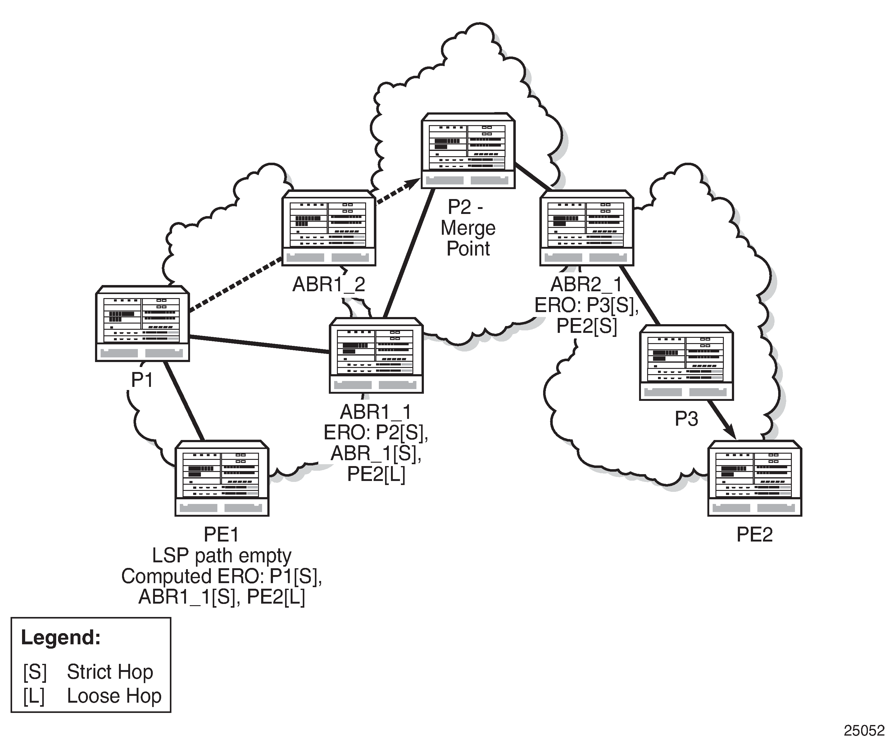
CSPF for an inter-area LSP operates as follows:
CSPF in the ingress LER node determines that an LSP is inter-area by performing a route lookup with the destination address of a point-to-point LSP, such as the address in the ‟to” field of the LSP configuration. If there is no intra-area route to the destination address, the LSP is considered to be inter-area.
When the path of the LSP is empty, CPSF computes a single-segment, intra-area path to an ABR that advertised a prefix matching the destination address of the LSP.
If the path of the LSP contains one or more hops, CSPF computes a multi-segment, intra-area path including the hops that are in the area of the ingress LER node.
If all hops are in the area of the ingress LER, the calculated path ends on an ABR that advertised a prefix matching the destination address of the LSP.
When there are one or more hops that are not in the area of the ingress LER, the calculated path ends on an ABR that advertised a prefix matching the first-hop address that is not in the area of the ingress LER.
Note the following special case of a multi-segment, inter-area LSP. If CSPF hits a hop that can be reached via an intra-area path but that resides on an ABR, CSPF only calculates a path up to that ABR. This is because there is a better chance to reach the destination of the LSP by first signaling the LSP up to that ABR and continuing the path calculation from there on by having the ABR expand the remaining hops in the ERO.
If there is more than one ABR that advertised a prefix, CSPF calculates a path for all ABRs. Only the shortest path is withheld. If more than one path is the shortest path, CSPF picks a path randomly or based on the least-fill criterion if least-fill is enabled. If more than one ABR satisfies the least-fill criterion, CSPF also picks one path randomly.
The path for an intra-area LSP cannot exit and re-enter the local area of the ingress LER. This behavior was possible in prior implementations when the user specified a loose hop outside the local area or when the only available path was via TE links outside the local area.
Rerouting of Inter-area LSPs
In prior implementations, an inter-area LSP path would have been rerouted if a failure or a topology change occurred in the local area or in a remote area while the ABR loose hop in the path definition was still up. If the transit/inter-area (exit) ABR failed or was put into node TE graceful shutdown, or if IS-IS went into overload mode, the LSP path would remain down at the ingress LER.
With automatic ABR selection, the ingress LER can reroute an inter-area LSP primary path via a different ABR in the following situations:
When the local exit ABR fails, there are two cases to consider:
If the primary path is not protected at the ABR, and is therefore torn down by the previous hop in the path, then the ingress LER retries the LSP primary path via the ABR that currently has the best path for the destination prefix of the LSP.
If the primary path is protected at the ABR with a manual or dynamic bypass LSP, the ingress LER will receive a PathErr message with a notification of protection becoming active downstream and a RESV message with a Local-Protection-In-Use flag set. At the receipt of the first of these two messages, the ingress LER performs a Global Revertive MBB procedure to optimize the LSP primary path via the ABR that currently has the best path for the destination prefix of the LSP.
When the local exit ABR node goes into IS-IS overload or is put into node TE graceful shutdown, the ingress LER performs an MBB procedure to optimize the LSP primary path via the ABR that currently has the best path for the destination prefix of the LSP. The MBB is performed at the receipt of the PathErr message for the node TE shutdown, or at the next timer or manual optimization of the LSP path if the IS-IS overload bit is received.
Behavior of MPLS Options in Inter-area LSPs
The automatic ABR selection for an inter-area LSP does not change the prior implementation of inter-area LSP behavior for many of the LSP-level and path-level options. However, there are a number of enhancements introduced by the automatic ABR selection feature.
Features such as path bandwidth reservation and admin-groups continue to operate within the scope of all areas since they rely on propagating the parameter information in the PATH message across the area boundary.
The TE graceful shutdown feature continues to support MBB of the LSP path to avoid the link or node that originated the PathErr message as long as the link or node is in the local area of the ingress LER. If the PathErr originated in a remote area, the ingress LER is not able to avoid the link or node when it performs the MBB since it computes the path to the local exit ABR only. However, there is an exception to this. An enhancement has been added to cause the upstream ABRs in the current path of the LSP to record the link or node to avoid and use the record in subsequent ERO expansions. This means that if the ingress LER computes a new MBB path that goes through the same exit ABR as the current path, and all ABRs upstream of the node or link that originated the PathErr message are also selected in the new MBB path when the ERO is expanded, then the new path will also avoid this link or node.
MBB support has been expanded to avoid the ABR when the node is put into TE graceful shutdown.
The use-te-metric option in CSPF cannot be propagated across the area boundary and therefore operates within the scope of the local area of the ingress LER. This is a new behavior.
The srlg option on the bypass LSP continues to operate locally at each PLR within each area. The PLR protecting the ABR checks the SRLG constraint for the path of the bypass within the local area.
The srlg option on the secondary path is allowed to operate within the scope of the local area of the ingress LER with the automatic ABR selection feature.
The least-fill option support with an inter-area LSP is introduced with the automatic ABR selection feature. When this option is enabled, CSPF applies the least-fill criterion to select the path segment to the exit ABR in the local area.
The PLR must indicate to CSPF that a request to a one-to-one detour LSP path must remain within the local area. If the destination for the detour, which is the same as that of the LSP, is outside of the area, CSPF must return no path.
With the automatic ABR selection feature, timer-based resignaling of the inter-area LSP path is supported and the path is resignaled if the cost of the path segment to the local exit ABR changes. The cost shown for the inter-area LSP at the ingress LER is the cost of the path segments to the ABR.
Inter-area LSP Support of OSPF Virtual Links
The OSPF virtual link extends area 0 for a router that is not connected to area 0 (OSPF backbone area). All prefixes in area 0 appear to be reachable via an intra-area path. However, the prefixes are not reachable since the path crosses the transit area through which the virtual link is set up to reach the area 0 remote nodes.
The TE database in a router learns all of the remote TE links in area 0 from the ABR connected to the transit area, but an intra-area LSP path using these TE links cannot be signaled within area 0 since none of these links are directly connected to this node.
The inter-area LSP feature can identify when the destination of an LSP is reachable via a virtual link. In that case, CSPF automatically computes and signals an inter-area LSP via the ABRs that are connected to the transit area.
However, when the ingress LER for the LSP is the ABR connected to the transit area, and the destination of the LSP is the address corresponding to another ABR router-id in that same transit area, CSPF computes and signals an intra-area LSP using the transit area TE links, even when the destination router-id is only part of area 0.
ABR FRR Protection for Inter-area LSP
For protection of the ABR, the upstream node of the ABR acts as a PLR, and the next-hop node to the protected domain border router is the merge point (MP). Both manual and dynamic bypass are available to protect the ABR.
Manual bypass protection only works when a proper completely strict path is provisioned that avoids the ABR.
Dynamic bypass protection provides for the automatic computation, signaling, and association with the primary path of an inter-area point-to-point LSP to provide ABR protection. ABR Protection Using Dynamic Bypass LSP illustrates the role of each node in ABR protection using a dynamic bypass LSP.
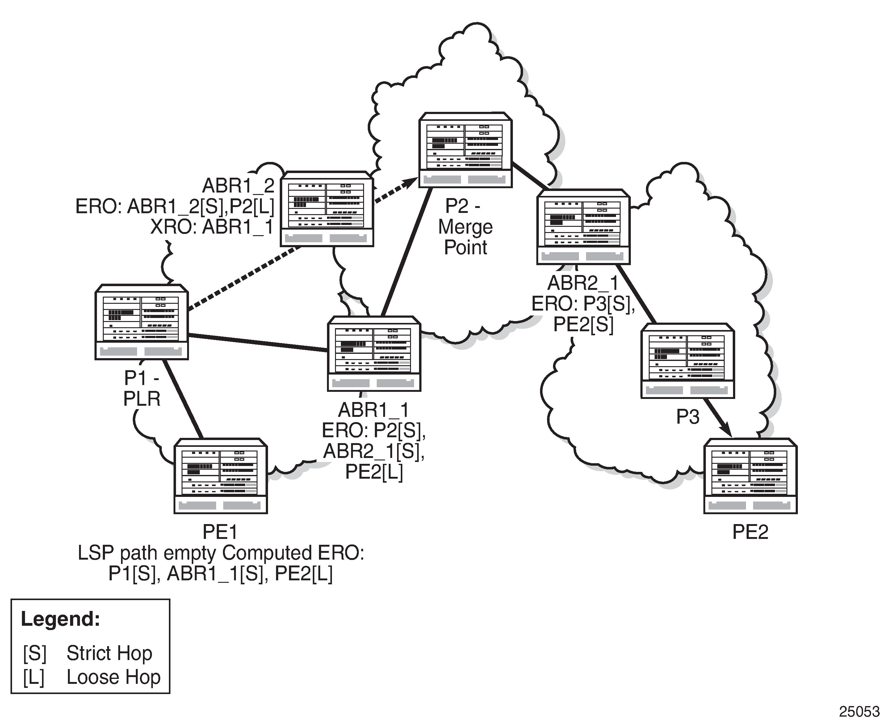
In order for a PLR within the local area of the ingress LER to provide ABR protection, it must dynamically signal a bypass LSP and associate it with the primary path of the inter-area LSP using the following procedures.
The PLR must inspect the RRO node-id of the LSP primary path to determine the address of the node immediately downstream of the ABR in the other area.
The PLR signals an inter-area bypass LSP with a destination address set to the address downstream of the ABR and with the exclude route object (XRO) set to exclude the node-id of the protected ABR.
The request to CSPF is for a path to the merge point (that is, the next-next-hop in the RRO received in the RESV message for the primary path) along with the constraint to exclude the protected ABR and the include/exclude admin groups of the primary path. If CSPF returns a path that can only go to an intermediate hop, then the PLR signals the dynamic bypass and automatically includes the XRO with the address of the protected ABR and propagates the admin-group constraints of the primary path into the Session Attribute object of the bypass LSP. Otherwise, the PLR signals the dynamic bypass directly to the merge point node with no XRO in the PATH message.
If a node-protect dynamic bypass cannot be found or signaled, the PLR attempts a link-protect dynamic bypass LSP. As with the existing implementation of dynamic bypass within the same area, the PLR attempts in the background to signal a node-protect bypass at the receipt of every third RESV refresh message for the primary path.
Refresh reduction over dynamic bypass only works if the RRO node-id also contains the interface address. Otherwise, the neighbor is not created once the bypass is activated by the PLR. The Path state then times out after three refreshes following the activation of the bypass backup LSP.
A one-to-one detour backup LSP cannot be used at the PLR for the protection of the ABR. As a result, a 7705 SAR, acting as a PLR, will not signal a one-to-one detour LSP for ABR protection. In addition, an ABR will reject a PATH message, received from a third party implementation, with a detour object and with the ERO having the next hop loose. This is performed whether the cspf-on-loose option is enabled or not on the 7705 SAR. In other words, the 7705 SAR, working as a transit ABR for the detour path, rejects the signaling of an inter-area detour backup LSP.
Preference Option for Standby Secondary LSP Paths
The path-preference command allows priority values to be assigned to standby secondary LSP paths. This command can only be used for secondary LSP paths that have been configured in standby mode.
When the primary LSP becomes inactive, the standby secondary LSP with the highest path priority (lowest path-preference value) is chosen from the qualifying standby secondary LSPs to become the active LSP. This functionality allows a user to choose a path for one of the standby secondary LSPs that may, for example, be over a more reliable link or over a link with a lower latency.
If multiple standby secondary LSP paths have the same priority value, the system selects the path with the lowest uptime.
RSVP-TE Fast Reroute (FRR)
FRR is a mechanism to protect against RSVP-TE signaled LSP failures by reacting to these failures as soon as possible. FRR is set up from the iLER, which signals the transit routers to precompute their backup LSPs. FRR creates a precomputed backup LSP from each node in the LSP path. If a link or LSP between two routers fails, traffic is rerouted immediately onto the precomputed backup LSP.
The 7705 SAR supports FRR facility backup and one-to-one backup.
Facility backup mode allows FRR to be enabled on an aggregate basis and protects a whole node or a whole link, regardless of the number of LSPs using that link. In other words, facility backup mode creates a common bypass tunnel to protect all LSP paths traversing a common facility path. It provides flexibility, faster provisioning, and faster convergence times compared with one-to-one backup or LSP redundancy. One-to-one backup allows FRR to be enabled on a per-LSP basis.
With both methods, MPLS switches build many possible detour routes on the nodes between the ingress and egress nodes of an LSP. The facility backup method creates a detour route between two nodes, called a bypass tunnel, which is a single tunnel that follows the primary LSP path except where the link or node has failed. Traffic then switches to the bypass tunnel. The bypass tunnel merges with the original LSP path at the merge point (MP) as soon as possible. The one-to-one backup method creates a detour route, called a detour LSP, for each LSP that needs to be rerouted. Unlike the bypass tunnel, the detour LSP takes the best path to the termination point, and does not merge with the original LSP as soon as possible. The detour LSPs of a one-to-one backup LSP can merge at a detour merge point (DMP), which can either be at the termination point or at a point along the primary LSP.
One of the major differences between facility and one-to-one backup is the scalability offered by the protection method. In facility backup mode, all LSPs of the same type are rerouted over the bypass tunnel. Hence they are all protected against the failure of a node or link in the network. In facility backup mode, each LSR along the path verifies that it has a bypass tunnel available to meet its requirements; otherwise, if it can, it signals a new bypass tunnel based on the requirements. If a new LSP is configured for FRR facility backup, the existing backup tunnels are scanned and if any one of them can be used for recovery, it is preferred. If there are no common links, then a new bypass tunnel will be signaled, assuming that the LSP requirements can be met. One-to-one backup mode uses similar reroute and protection methods except a detour route is applied on a per-LSP basis.
The 7705 SAR uses CSPF to calculate the explicit route and dynamically signal the FRR LSP.
With facility backup mode, routers check the contents of the Record Route Object (RRO) in the received RESV message to determine the bypass tunnel endpoint in the FRR facility. For link protection, the router uses the RRO to check the IP address of the next-hop router attached to the far end of the link along with the label allocation information and to build the bypass tunnel. This label is preserved until the LSP is merged at the MP. For node protection, the router uses the RRO to determine the next-next-hop router and the label it is expecting. The collection of RRO information is enabled through the record and record-label options.
If, after this process, another LSP requests FRR using the facility backup method, the router checks and compares its session object to the existing session objects and if there is a match, the router binds that LSP to the same bypass tunnel. If there is no match, another bypass is created.
FRR Terminology
FRR Terminology provides definitions of terms used for FRR.
Term |
Definition |
|---|---|
Backup path |
The LSP that is responsible for backing up a protected LSP. A backup path can be a backup tunnel (facility backup) or a detour LSP (one-to-one backup). |
Backup tunnel |
The LSP that is used to back up one of the many LSPs in FRR facility (many-to-one) backup |
Bypass tunnel |
An LSP that is used to protect a set of LSPs passing over a common facility in FRR facility backup. A bypass tunnel can be configured manually or dynamically (see Dynamic and Manual Bypass LSPs). |
CSPF |
Constraint-based shortest path first |
Detour route |
Any alternate route that protects the primary path, such as a secondary path, FRR bypass tunnel, or FRR detour LSP. The term ‟detour route” should not be confused with the term ‟detour LSP”. Detour route is a general term that refers to any alternate route, while detour LSP is a specific term that applies to one-to-one backup. |
Detour LSP |
The LSP that is used to reroute traffic around a failure in FRR one-to-one backup. The term ‟detour LSP” should not be confused with the term ‟detour route”. Detour route is a general term that refers to any alternate route, while detour LSP is a specific term that applies to one-to-one backup. |
DMP |
Detour merge point In the case of one-to-one backup, this is an LSR where multiple detours converge. Only one detour is signaled beyond that LSR. |
Disjoint |
See SRLG disjoint |
Facility backup |
A local repair method in which a single bypass tunnel is used to protect one or more LSPs that traverse the PLR, the resource being protected, and the Merge Point (in that order). Facility backup is distinct from a one-to-one backup tunnel, which has one backup path per protected path. |
MP |
Merge point The LSR where one or more backup tunnels rejoin the path of the protected LSP downstream of the potential failure. The same LSR may be both an MP and a PLR simultaneously. |
NHOP bypass tunnel |
Next-hop bypass tunnel A backup tunnel that bypasses a single link of the protected LSP |
NNHOP bypass tunnel |
Next-next-hop bypass tunnel A backup tunnel that bypasses a single node of the protected LSP |
One-to-one backup |
A local repair method in which a backup LSP is separately created for each protected LSP at a PLR |
PLR |
Point of local repair The head-end router of a backup tunnel or a detour LSP, where the term local repair refers to techniques used to repair an LSP tunnel quickly when a node or link along an LSP path fails |
Primary path |
An LSP that uses the routers specified by the path defined by the primary path-name command |
Protected LSP |
An LSP is protected at a given hop if it has one or more associated backup tunnels originating at that hop |
Reroutable LSP |
Any LSP for which the head-end router requests local protection |
Secondary path |
An LSP that protects a primary path that uses LSP redundancy protection rather than FRR protection |
|
SRLG disjoint |
A path is considered to be SRLG disjoint from a given link or node if the path does not use any links or nodes that belong to the same SRLG as the given link or node |
Bypass Resignal Timer
When the bypass resignal timer is enabled, MPLS makes a request to CSPF for the best path for each dynamic bypass LSP originated on the node. The constraints of the first associated LSP primary path that originally triggered the signaling of the bypass LSP must be satisfied. In order to do this, MPLS saves the original Path State Block (PSB) of the LSP primary path, even if the path is torn down.
If CSPF returns no path or returns a new path that is equal in cost to the current path, the PSB associations are not updated. If CSPF returns a new path with a different cost from the current one, MPLS signals it.
When the new path is successfully signaled, MPLS evaluates each PSB of each PLR (that is, each unique avoid-node or avoid-link constraint) associated with the older bypass LSP path to check whether the corresponding LSP primary path constraints are still satisfied by the new bypass LSP path. If the constraints are satisfied, the PSB association is moved to the new bypass LSP.
If the constraints are not satisfied, the PSB remains associated with the older bypass LSP and will be checked at the next background PSB re-evaluation or at the next timed or manual bypass reoptimization. Additionally, if the older bypass LSP is SRLG disjoint with a primary path that has the non-strict SRLG condition and the new bypass LSP is not SRLG disjoint, the PSB association is not moved.
If a PLR associated with a bypass LSP is active, the corresponding PSBs remain associated with the older bypass LSP until the global revertive make-before-break (MBB) operation tears down all corresponding primary paths, which also causes the older bypass LSP to be torn down.
When the bypass resignal timer is configured, a PSB re-evaluation task is initiated that runs in the background of each RSVP-TE session to determine whether an existing manual or dynamic bypass is more optimal for that session. If the PSB re-evaluation task finds a more optimal bypass, it moves the PSB association to it. If the PLR for this session is active, no action is taken and the PSB is re-examined at the next re-evaluation.
The periodic bypass reoptimization feature evaluates only the PSBs of the PLRs associated with that bypass LSP and only against the new bypass LSP path. The background re-evaluation task will, however, audit all PSBs on the system against all existing manual and dynamic bypass LSPs. PSBs that have not been moved by the dynamic or manual reoptimization of a bypass LSP, due to the PSB constraints not being met by the new signaled bypass LSP path, will be re-evaluated by the background task against all existing manual and dynamic bypass LSPs.
The background re-evaluation task also checks for PSBs that have requested a node-protect bypass LSP but are currently associated with a link-protect bypass LSP, as well as PSBs that have requested FRR protection and have no association. The background task is in addition to the attempt made when an RESV message is received on the protected LSP path, which ensures the association is completed faster.
This feature is not supported with inter-area dynamic bypass LSPs.
FRR Behavior
The FRR MPLS facility backup method and one-to-one backup method are configured on the ingress LER (iLER) by using the fast-reroute command.
The behavior of an LSP at an iLER with both FRR and a standby LSP path configured is as follows.
When a downstream detour route (alternative path) becomes active at a Point of Local Repair (PLR):
The iLER switches to the standby LSP path as soon as it is notified of the reroute. If the primary LSP path is subsequently repaired at the PLR, the LSP switches back to the primary path. If the standby path goes down, the LSP is switched back to the primary path, even though the primary path is still on the detour route at the PLR.
If the primary path goes down at the iLER while the LSP is on the standby path, the detour route at the iLER is torn down and, for one-to-one backup detour routes, a ‟path tear” is sent for the detour route. In other words, the detour route at the iLER does not protect the standby LSP. If and when the primary LSP is again successfully resignaled, the iLER detour route will be restarted.
When the primary LSP fails at the iLER:
The LSP switches to the detour route. If the primary path undergoes a global revertive recovery, the LSP switches back to the primary path. If the LSP is on the detour route and the detour route fails, the LSP is switched to the standby path.
Administrative groups are not taken into account when creating the detour routes for LSPs.
Dynamic and Manual Bypass LSPs
Users can disable dynamic bypass creation on a per-node basis using the config>router>mpls>dynamic-bypass command. Disabling dynamic bypass means that manual bypass is enabled. Dynamic bypass is enabled by default.
Dynamic bypass tunnels are implemented as per RFC 4090, Fast Reroute Extensions to RSVP-TE for LSP Tunnels. When an LSP is signaled and the Local Protection flag in the Session_attribute object is set, or the FRR object in the PATH message indicates that facility backup is desired, the PLR establishes a bypass tunnel to provide node and link protection. If there exists a bypass LSP that merges with the protected LSP at a downstream node, and if this LSP satisfies the constraints in the FRR object, then this bypass tunnel is selected and used. The frr-object command specifies whether facility backup is signaled in the FRR object.
The manual bypass feature allows an LSP to be preconfigured from a Point of Local Repair (PLR) that will be used exclusively for bypass protection. When a PATH message for a new LSP requests bypass protection, the node first checks for a manual bypass tunnel that satisfies the path constraints. If one is found, it is selected and used. If no manual bypass tunnel is found, the 7705 SAR dynamically signals a bypass LSP in the default behavior. To configure a manual bypass LSP, use the bypass-only option in the config>router>mpls>lsp lsp-name [bypass-only] command.
When a PLR activates a bypass backup LSP and subsequently receives a RESV refresh message for the original primary LSP path reservation over the restored interface, the PLR does not generate a ResvErr packet downstream. In addition, the MP node, once it becomes active, does not propagate a downstream ResvErr message received packet for the original primary LSP path reservation.
See Configuring Manual Bypass Tunnels for configuration information.
Bypass LSP Selection Rules for the PLR
Bypass Tunnel Node Example shows an example of a network used to illustrate the LSP selection rules for a PLR bypass scenario.
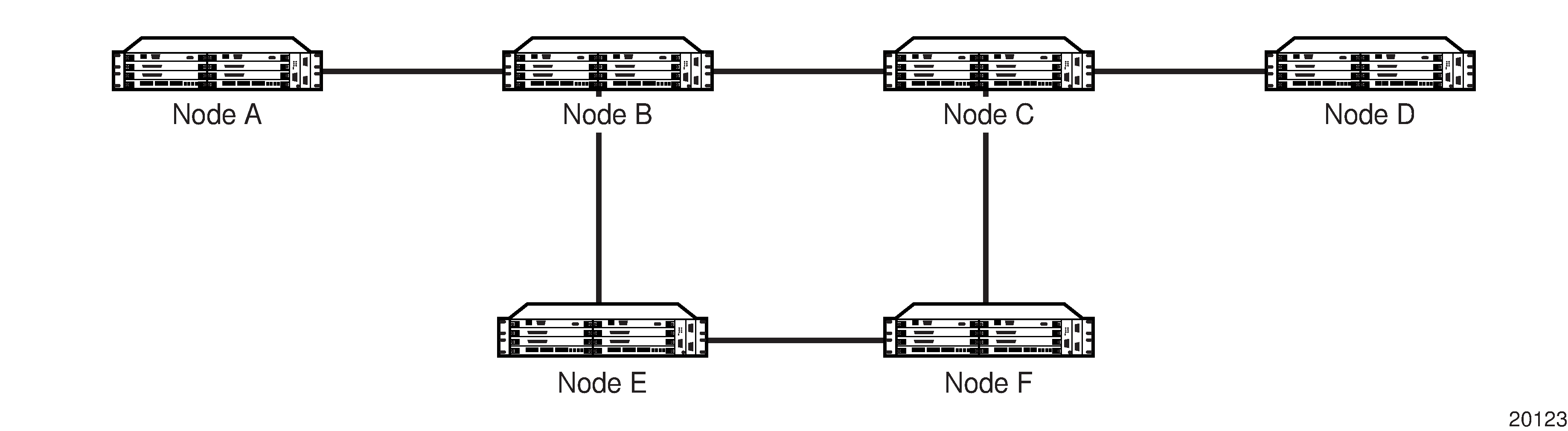
The PLR uses the following rules to select a bypass LSP from among multiple bypass LSPs (manually and dynamically created) when establishing the primary LSP path or when searching for a bypass for a protected LSP that does not have an association with a bypass tunnel.
The MPLS/RSVP-TE task in the PLR node checks for an existing manual bypass tunnel that satisfies the constraints. If the PATH message for the primary LSP path indicated that node protection is desired, which is the default LSP FRR setting at the head-end node, then the MPLS/RSVP-TE task searches for a node-protect bypass LSP. If the PATH message for the primary LSP path indicated that link protection is desired, then it searches for a link-protect bypass LSP.
If multiple manual bypass LSPs satisfying the path constraints exist, the PLR will prefer a manual bypass LSP terminating closer to the PLR over a manual bypass LSP terminating further away. If multiple manual bypass LSPs satisfying the path constraints terminate on the same downstream node, the PLR selects the one with the lowest IGP path cost, or if there is a tie, it picks the first one available.
If none of the manual bypass LSPs satisfy the constraints and dynamic bypass tunnels have not been disabled on the PLR node, then the MPLS/RSVP-TE task in the PLR node checks to determine if any of the already established dynamic bypass LSPs of the requested type satisfy the constraints.
If none of the dynamic bypass LSPs satisfy the constraints, then the MPLS/RSVP-TE task will ask CSPF to check if a new dynamic bypass of the requested type, node-protect or link-protect, can be established.
If the PATH message for the primary LSP path indicated node protection is desired, and no manual bypass was found after Step 1, and/or no dynamic bypass LSP was found after three attempts to perform Step 3, the MPLS/RSVP-TE task will repeat Steps 1 to 3 looking for a suitable link-protect bypass LSP. If none are found, the primary LSP will have no protection and the PLR node must clear the Local Protection Available flag in the IPv4 address sub-object of the RRO, starting in the next RESV refresh message it sends upstream.
If the PATH message for the primary LSP path indicated link protection is desired, and no manual bypass was found after Step 1, and/or no dynamic bypass LSP was found after performing Step 3, the primary LSP will have no protection and the PLR node must clear the Local Protection Available flag in the IPv4 address sub-object of the RRO, starting in the next RESV refresh message it sends upstream. The PLR will not search for a node-protect bypass LSP in this case.
If the PLR node successfully makes an association, it must set the Local Protection Available flag in the IPv4 address sub-object of the RRO, starting in the next RESV refresh message it sends upstream.
For all primary LSPs that requested FRR protection but are not currently associated with a bypass tunnel, the PLR node—upon reception of an RESV refresh message on the primary LSP path—repeats Steps 1 to 7.
If the user disables dynamic bypass tunnels on a node while dynamic bypass tunnels are activated and passing traffic, traffic loss will occur on the protected LSP. Furthermore, if no manual bypass tunnel exists that satisfies the constraints of the protected LSP, the LSP will remain without protection.
If the user configures a bypass tunnel on Node B (Bypass Tunnel Node Example) and dynamic bypass tunnels have been disabled, LSPs that had been previously signaled and that were not associated with any manual bypass tunnel (for example, none existed) will be associated with the manual bypass tunnel, if it is suitable. The node checks for the availability of a suitable bypass tunnel for each of the outstanding LSPs every time an RESV message is received for these LSPs.
If the user configures a bypass tunnel on Node B and dynamic bypass tunnels have not been disabled, LSPs that had been previously signaled over dynamic bypass tunnels will not automatically be switched to the manual bypass tunnel, even if the manual bypass tunnel is a more optimized path. The user must perform a make-before-break switchover at the head end of these LSPs. The make-before-break process is enabled using the adaptive option.
If the manual bypass tunnel goes into the down state on Node B and dynamic bypass tunnels have been disabled, Node B (PLR) will clear the ‟protection available” flag in the RRO IPv4 sub-object in the next RESV refresh message for each affected LSP. It will then try to associate each of these LSPs with one of the manual bypass tunnels that are still up. If it finds one, it will make the association and set the ‟protection available” flag in the next RESV refresh message for each of these LSPs. If it cannot find one, it will keep checking for one every time an RESV message is received for each of the remaining LSPs. When the manual bypass tunnel is back up, the LSPs that did not find a match are associated back with this tunnel and the protection available flag is set starting in the next RESV refresh message.
If the manual bypass tunnel goes into the down state on Node B and dynamic bypass tunnels have not been disabled, Node B will automatically signal a dynamic bypass tunnel to protect the LSPs if a suitable one does not exist. Similarly, if an LSP is signaled while the manual bypass tunnel is in the down state, the node will only signal a dynamic bypass tunnel if the user has not disabled dynamic tunnels. When the manual bypass tunnel is back up, the node will not switch the protected LSPs from the dynamic bypass tunnel to the manual bypass tunnel.
FRR Node Protection (Facility Backup)
The MPLS Fast Reroute (FRR) functionality enables PLRs to be aware of the lack of node protection and lets them regularly probe for a node bypass via the node-protect command.
When enabled, the node-protect command provides node protection for the specified LSP. If node protection cannot be provided, link protection is attempted. If link protection cannot be provided, no protection is provided. When disabled via the no form of the command, link protection is attempted, and if link protection cannot be provided, no protection is provided.
For example, assume the following for the LSP scenario in FRR Node-Protection Example.
LSP_1 is between PE_1 and PE_2 (via P1 and P2), and has CSPF, FRR facility backup, and FRR node protection enabled.
P1 protects P2 with bypass nodes P1 - P3 - P4 - PE_4 - PE_3.
If P4 fails, P1 tries to establish the bypass node three times.
When the bypass node creation fails (there is no bypass route), P1 will protect link P1-P2.
P1 protects the link to P2 through P1 - P5 - P2.
P4 returns online.
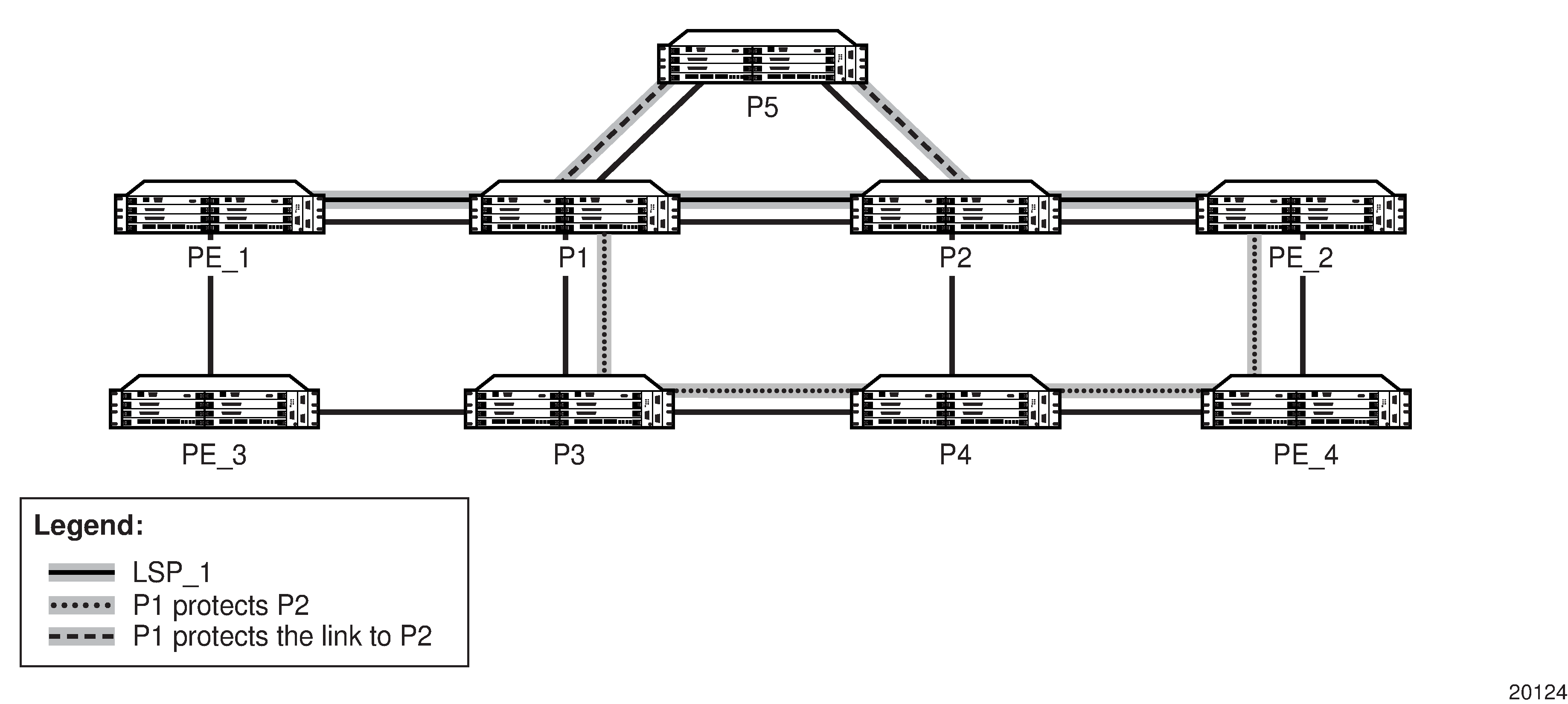
LSP_1 had requested node protection, but due to lack of an available path it could only obtain link protection. Therefore, every 60 s, the PLR for LSP_1 will search for a new path that might be able to provide node protection. When P4 is back online and such a path is available, a new bypass tunnel will be signaled and LSP_1 will be associated with this new bypass tunnel.
Admin Group Support on Facility Bypass Backup LSPs
Admin group support on facility bypass backup LSPs provides for the inclusion of the LSP primary path admin-group constraints in the computation of an FRR facility bypass backup LSP to protect the primary LSP path. Admin group constraints are honored by all nodes in the LSP path both for primary and FRR backup LSPs.
This feature is supported on primary paths of an RSVP point-to-point LSP in both intra-area and inter-area TE where applicable.
This feature is not supported on one-to-one detour backup LSPs.
FRR Over Unnumbered Interfaces
When the PLR is the ingress LER node and the outgoing interface of the bypass LSP is unnumbered, the user must assign a borrowed IP address to the interface that is different from the system interface; otherwise, the bypass LSP will not come up.
In addition, the PLR node includes the IF_ID RSVP_HOP object (C-Type = 3) in the PATH message if the outgoing interface of the bypass LSP is unnumbered. If the outgoing interface of the bypass LSP is numbered, the PLR node includes the IPv4 RSVP_HOP object (C-Type = 1).
When the MP node receives the PATH message over the bypass LSP, it creates the merge-point context for the protected LSP and associates it with the existing state if any of the following is satisfied:
-
the C-Type value of the RSVP_HOP object has changed
-
the C-Type is the value for the IF_ID RSVP_HOP object (C-Type = 3) and it has not changed, but the IF_ID TLV is different
-
the IPv4 Next/Previous Hop Address field in the RSVP_HOP object has changed, regardless of the C-Type value
This behavior at the PLR and MP nodes is the same for both link protection and node protection FRR.
See RSVP-TE Support for Unnumbered Interfaces for information about unnumbered interfaces.
Shared Risk Link Groups
A shared risk link group (SRLG) represents a set of interfaces (or links) that share the same risk of failing because they may be subjected to the same resource failures or defects. Two examples where the same risk of failure exists are fiber links that share the same conduit, and multiple wavelengths that share the same fiber.
SRLGs are supported by both LSP redundancy protection and FRR protection. SRLGs allow the user to prepare a detour route that is disjoint from the primary LSP path. See Disjoint and Non-disjoint Paths.
The SRLG feature ensures that a primary and secondary LSP path, or a bypass tunnel or detour LSP path, do not share SRLGs. That is, they do not share the same sets of links that are considered to have a similar (or identical) chance of failure.
To use SRLGs, the user first creates an SRLG by assigning one or more routers to the SRLG. Then, the user links the SRLG to an MPLS interface and enables the SRLG feature on the LSP path. SRLGs cannot be assigned to the system interface.
SRLGs for Secondary LSP Paths
SRLGs for secondary LSP paths apply when LSP redundancy protection is used.
When setting up the secondary path, enable the srlg option on the secondary path to ensure that CSPF includes the SRLG constraint in its route calculation. To make an accurate computation, CSPF requires that the primary LSP be established and in the up state (because the head-end LER needs the most current explicit route object (ERO) for the primary path, and the most current ERO is built during primary path CSPF computation). The ERO includes the list of SRLGs.
At the establishment of a secondary path with the SRLG constraint, the MPLS/RSVP-TE task queries CSPF again, which provides the list of SRLGs to be avoided. CSPF prunes all links having interfaces that belong to the same SRLGs as the interfaces included in the ERO of the primary path. If CSPF finds an eligible path, the secondary path is set up. If CSPF does not find an eligible path, MPLS/RSVP-TE keeps retrying the requests to CSPF.
SRLGs for FRR LSP Paths
When setting up the FRR bypass or detour LSP, enable the srlg-frr option on FRR to ensure that CSPF includes the SRLG constraint in its route calculation. CSPF prunes all links that are in the SRLG being used by the primary LSP during the calculation of the FRR path. If one or more paths are found, CSPF sets up the FRR bypass or detour LSP based on the best cost and signals the FRR LSP.
If there is no path found based on the above calculation and the srlg-frr command has the strict option set, then the FRR LSP is not set up and the MPLS/RSVP-TE task keeps trying to set up a path. If the strict option is not set, then the FRR LSP is set up based on the other TE constraints (that is, excluding the SRLG constraint).
Disjoint and Non-disjoint Paths
A path is considered to be SRLG disjoint from a given link (or node) if the path does not use any links (or nodes) that belong to the same SRLG as the given link (or node). Eligible disjoint paths are found by CSPF when the SRLG constraint is included in the CSPF route calculation (referred to as the strict SRLG condition).
When LSP redundancy is used, the secondary LSP is always signaled with a strict SRLG condition.
When FRR is used, the FRR bypass or detour LSP may have a strict or non-strict SRLG condition. If the strict option is used with the srlg-frr command, then the bypass LSP must be on the list of eligible paths found by the CSPF calculation that included the SRLG constraint. If the strict option is not used, then it is possible for the bypass or detour LSP to be non-disjoint. The non-disjoint case is supported only if the SRLG is not strict.
At the PLR, if an FRR tunnel is needed to protect a primary LSP, the priority order for selecting that FRR tunnel is as follows:
Manual bypass disjoint
Manual bypass non-disjoint (eligible only if srlg-frr is non-strict)
Dynamic bypass disjoint
Dynamic bypass non-disjoint (eligible only if srlg-frr is non-strict)
A bypass or a detour LSP path is not guaranteed to be SRLG disjoint from the primary path. This is because only the SRLG constraint of the outgoing interface at the PLR that the primary path is using is considered in the CSPF calculation.
Enabling Disjoint Backup Paths
A typical application of the SRLG feature is to provide automatic setup of secondary LSPs or FRR bypass or detour LSPs, in order to minimize the probability that they share the same failure risks with the primary LSP path (see Disjoint Primary and Secondary LSPs and Disjoint FRR Bypass LSPs).
Disjoint Primary and Secondary LSPs illustrates SRLG when LSP redundancy is used, where SRLG_1 contains the interfaces that define links A-B, B-C, and C-D. The primary path uses these links to connect node A to node D. In the event of a failure along the primary path, the secondary path cannot use any of the links in SRLG_1 and takes the path from node A to nodes E, F, G, H, J, and D.
Disjoint FRR Bypass LSPs illustrates SRLG when FRR bypass is used, where SRLG_1 is the same as in Disjoint Primary and Secondary LSPs. Since FRR bypass is used, the following possible reroutes may occur, depending on where the failure occurs:
if node B fails, the bypass is from node A to nodes E, F, G, H, and C
if node C fails, the bypass is from node B to nodes F, G, H, J, and D
if link C-D fails, the bypass is from node C to nodes H, J, and D
The SRLG feature is supported on OSPF and IS-IS interfaces for which RSVP-TE is enabled.
The following steps describe how to enable SRLG disjoint backup paths for LSP redundancy and FRR.
LSP Redundancy for Primary/Secondary (standby) SRLG Disjoint Configuration
Create an SRLG-group (similar to creating an admin group).
Link the SRLG-group to MPLS interfaces.
Configure primary and secondary LSP paths, and enable SRLG on the secondary LSP path. The SRLG secondary LSP paths will always perform a strict CSPF query.
The setting of the srlg-frr command is irrelevant in this case (see the srlg-frr command).
FRR Bypass Tunnel or Detour LSP SRLG Disjoint Configuration
Create an SRLG-group (similar to creating an admin group).
Link the SRLG-group to MPLS interfaces.
Enable the strict option on the srlg-frr command, which is a system-wide command that forces the CSPF calculation for every LSP path to take any configured SRLG memberships into account.
Configure primary FRR (facility backup or one-to-one backup) LSP paths. Each PLR will create a bypass or detour LSP that will only avoid the SRLG memberships configured on the primary LSP path egress interface. For one-to-one backup, detour-detour merging is out of the control of the PLR. The PLR will not ensure that the FRR detour will be prohibited from merging with a colliding detour LSP. For facility backup, given that there are several bypass types to bind to, the priority rules shown in Disjoint and Non-disjoint Paths are used.
Manually configured bypasses that do not use CSPF are not considered as possible backup paths.
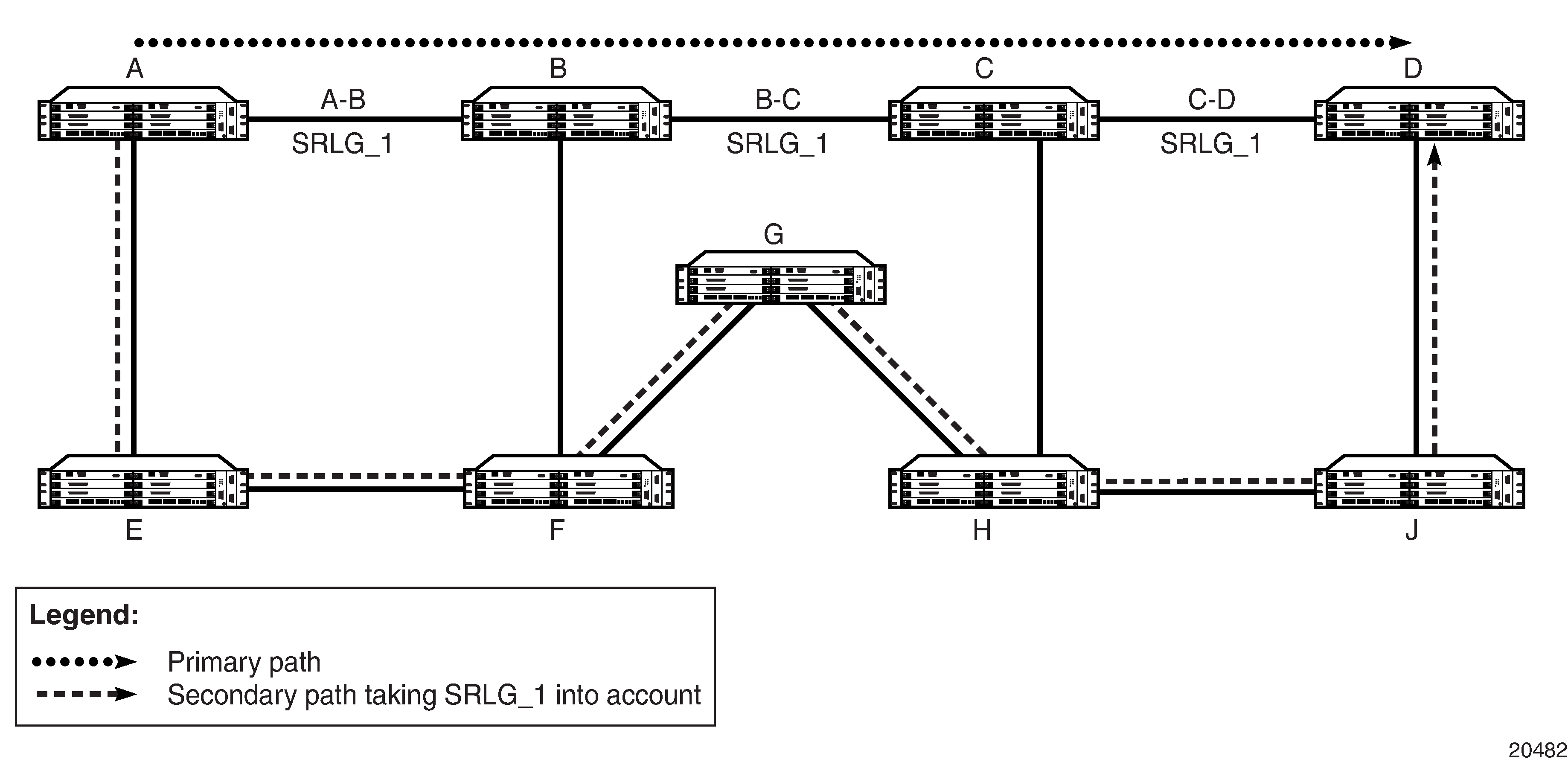
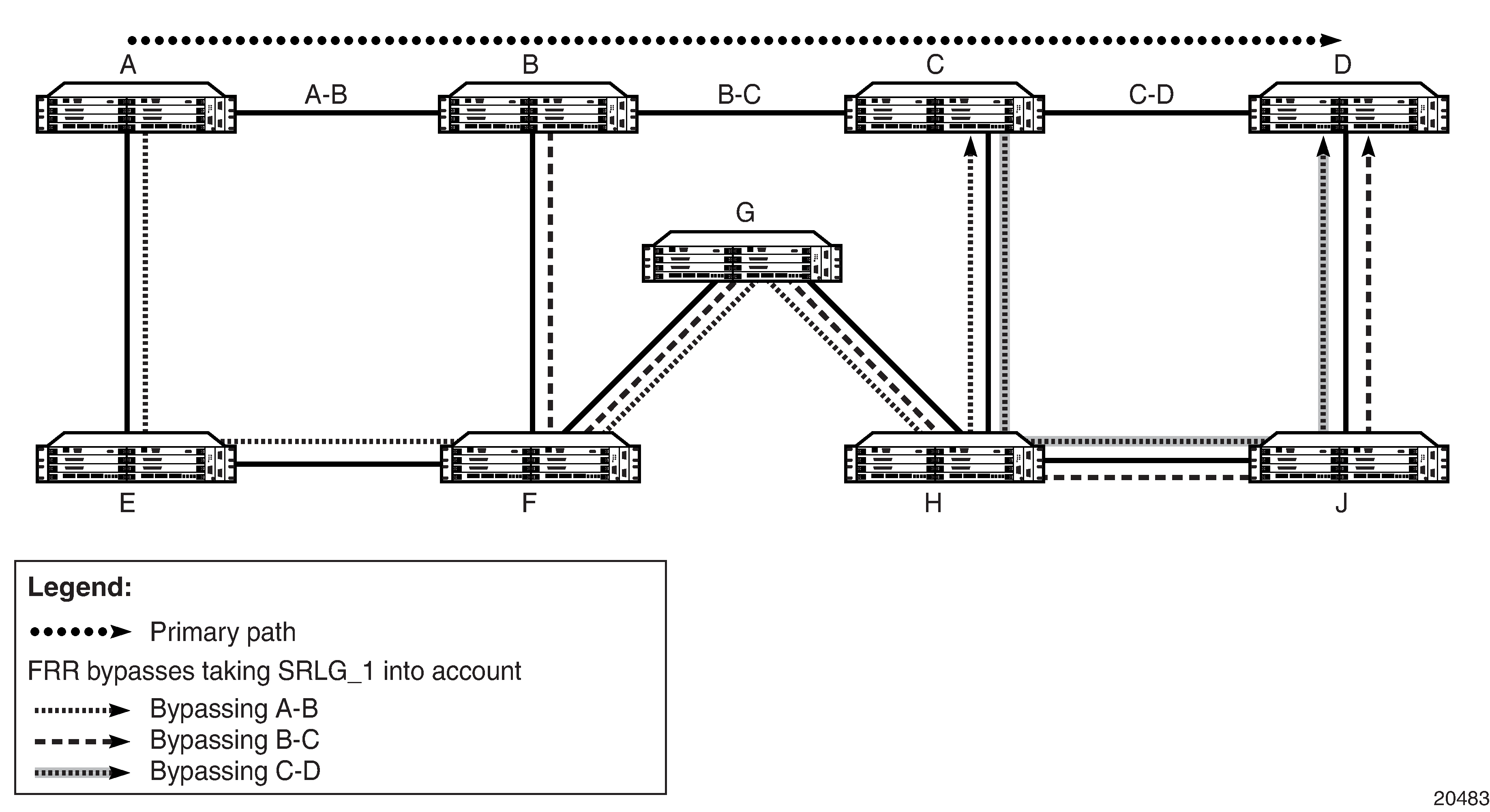
RSVP-TE Graceful Shutdown
RSVP-TE graceful shutdown provides a method to reroute transit LSPs in a bulk fashion away from a node prior to maintenance of that node. A PathErr message with the error code ‟Local Maintenance on TE Link required Flag” (if the affected network element is a link) or the error code ‟Local node maintenance required” (if the affected network element is the node) is sent before the links or node are taken out of service.
When an LER receives the message, it performs a make-before-break on the LSP path to move the LSPs away from the links/nodes whose IP addresses are indicated in the PathErr message and reroute them. Affected link/node resources are flagged in the TE database so that other routers will signal LSPs using the affected resources only as a last resort.
Graceful shutdown can be enabled on a per-interface basis or on all interfaces on the node if the whole node must be taken out of service.
RSVP-TE Support for Unnumbered Interfaces
Unnumbered interfaces are point-to-point interfaces that are not explicitly configured with a dedicated IP address and subnet; instead, they borrow (or link to) an IP address from another interface on the system (the system IP address, another loopback interface, or any other numbered interface) and use it as the source IP address for packets originating from the interface. For more information about support for unnumbered interfaces, see the 7705 SAR Router Configuration Guide, Unnumbered Interfaces.
Unnumbered IP interfaces can be used via RSVP-TE for signaling traffic engineering (TE) LSPs.
Supporting RSVP-TE over unnumbered interfaces requires the ability to:
carry TE information over unnumbered links in IS-IS-TE or OSPF-TE extensions
specify unnumbered interfaces in RSVP-TE signaling
An unnumbered IP interface is identified uniquely on a router in the network by the tuple (router ID, ifindex). An LSR at each end of the link assigns a system-wide unique interface index to the unnumbered interface. IS-IS, OSPF, MPLS (RSVP-TE, LDP), and OAM use this tuple to advertise the link information, signal LSPs over the interface, or send and respond to an MPLS echo request message over an unnumbered interface.
The borrowed IP address for an unnumbered interface is configured using the following CLI command, with the default value set to the system interface address: config>router>interface>unnumbered {ip-int-name | ip-address}.
To support unnumbered TE links in IS-IS, a new sub-TLV of the extended IS reachability TLV is added, which encodes the link local identifiers and link remote identifiers as defined in RFC 5307, IS-IS Extensions in Support of Generalized Multi-Protocol Label Switching (GMPLS).
To support unnumbered TE links in OSPF, a new sub-TLV of the Link TLV is added, which encodes the link local identifiers and link remote identifiers as defined in RFC 4203, \OSPF Extensions in Support of Generalized Multi-Protocol Label Switching (GMPLS).
To support unnumbered TE links in RSVP-TE, a new sub-object of the Explicit Route Object (ERO) is added to specify unnumbered links and a new sub-object of the Route Record Object (RRO) is added to record that the LSP traversed an unnumbered link, as per RFC 3477, Signalling Unnumbered Links in Resource ReSerVation Protocol - Traffic Engineering (RSVP-TE). As well, a new IF_ID RSVP_HOP object with a C-Type of 3 is added as per section 8.1.1 of RFC 3473, Generalized Multi-Protocol Label Switching (GMPLS) Signaling Resource ReserVation Protocol-Traffic Engineering (RSVP-TE) Extensions. The IPv4 Next/Previous Hop Address field in the object is set to the borrowed IP interface address.
The unnumbered IP interface address is advertised by IS-IS-TE or OSPF-TE, and CSPF can include it in the computation of a path for a point-to-point LSP. However, this feature does not support defining an unnumbered interface as a hop in the path definition of an LSP.
A router creates an RSVP neighbor over an unnumbered interface using the tuple (router ID, ifindex). The router ID of the router that advertised an unnumbered interface index is obtained from the TE database. Therefore, if traffic engineering is disabled in IS-IS or OSPF, a non-CSPF LSP that has its next hop over an unnumbered interface will not come up at the ingress LER because the router ID of the neighbor that has the next hop of the PATH message cannot be looked up. The LSP path will remain operationally down with the error ‟noRouteToDestination”. If a PATH message is received at the LSR for which traffic engineering was disabled and the next hop for the LSP is over an unnumbered interface, a PathErr message is sent back to the ingress LER with the error code of 24 ‟Routing Problem” and an error value of 5 ‟No route available toward destination”.
All MPLS (RSVP-TE and LDP) features supported for numbered IP interfaces are supported for unnumbered interfaces, with the following exceptions:
configuration of a router ID with a value other than system interface
signaling of an LSP with an ERO based on a loose or strict hop using an unnumbered TE link in the path hop definition
signaling of a one-to-one detour LSP over an unnumbered interface
RSVP Hello messages and all Hello-related capabilities, such as Graceful-Restart Helper
RSVP refresh reduction on an unnumbered interface
The unnumbered interface feature also extends the support of LSP ping and LSP traceroute to point-to-point LSPs that have unnumbered TE links in their path.
PCEP Support for RSVP-TE LSPs
The Path Computation Element Communication Protocol (PCEP) is one of several protocols used for communication between a wide area network (WAN) software-defined network (SDN) controller and network elements.
The 7705 SAR operates as a PCE Client (PCC) only, supporting PCC capabilities for RSVP-TE LSPs.
The following MPLS-level and LSP-level CLI commands are used to configure RSVP-TE LSPs in a router acting as a PCC. See MPLS and RSVP-TE Command Reference for command descriptions. See the PCEP Support for RSVP-TE LSPs section in the PCEP chapter for information about using these commands.
-
config>router>mpls>
pce-report rsvp-te {enable | disable}
-
config>router>mpls>lsp>
path-profile profile-id [path-group group-id]
path-computation-method pce
pce-control
pce-report {enable | disable | inherit}
-
config>router>mpls>lsp-template>
pce-report {enable | disable | inherit}
Segment Routing with Traffic Engineering (SR-TE)
Segment routing adds the ability to perform shortest path routing and source routing using the concept of abstract segments to IS-IS and OSPF routing protocols. A segment can represent a local prefix of a node, a specific adjacency of the node (interface/next hop), a service context, or a specific explicit path over the network. For each segment, the IGP advertises an identifier referred to as a Segment ID (SID).
When segment routing is used together with the MPLS data plane, the SID is a standard MPLS label. A router forwarding a packet using segment routing will therefore push one or more MPLS labels.
Segment routing using MPLS labels can be used in both shortest path routing applications (see the 7705 SAR Routing Protocols Guide for information) and in traffic engineering (TE) applications, as described in this section.
The following are the objectives and applications of segment routing:
ability for a node to specify a unicast shortest-route or source-routed forwarding path with the same mechanism; IGP can be reused to minimize the number of control plane protocols
ability to use IGP-based MPLS tunnels without the addition of any other signaling protocol
ability to tunnel services from ingress PE to egress PE with or without an explicit path and without requiring forwarding plane or control plane state in intermediate nodes
ability to use Layer 3 spoke SDP interfaces to support multicast for segment routing. See the 7705 SAR Routing Protocols Guide, ‟Multicast for Segment Routing”.
FRR: ability to expand coverage of basic LFA to any topology with the use of a source-routed backup path; precomputation and setup of backup path without additional signaling
support for LFA policies with shared-risk constraints, admin-groups, and link/node protection
support for SR-TE entropy labels
support for TE that includes loose/strict options, distributed and centralized TE, path disjointness, ECMP awareness, and limited or no per-service state on midpoint and tail-end routers
support for fine-grained flow steering and service chaining via a centralized stateful Path Computation Element (PCE) such as the one provided by the Nokia Network Services Platform (NSP)
SR-TE Support
The following MPLS commands and modes are supported:
global [router] MPLS-level commands and modes:
interface, lsp, path, shutdown, sr-te-resignal-timer
LSP-level commands and modes:
bfd, bgp-transport-tunnel, exclude, hop-limit, include, label-stack-reduction, local-sr-protection, metric, path-computation-method, primary, metric-type, retry-limit, retry-timer, shutdown, to, from, vprn-auto-bind
primary path-level commands and modes:
bandwidth, bfd, exclude, hop-limit, include, shutdown
secondary path-level commands and modes:
bandwidth, bfd, exclude, hop-limit, include, path-preference, shutdown, standby
The following MPLS commands and modes are not supported:
global MPLS-level commands and modes not applicable to SR-TE LSPs (configuration is ignored):
admin-group-frr, auto-lsp, bypass-resignal-timer, cspf-on-loose-hop, dynamic-bypass, frr-object, hold-timer, least-fill-min-thd, least-fill-reoptim-thd, logger-event-bundling, lsp-template, srlg-frr, static-lsp, static-lsp-fast-retry
LSP-level commands and modes not supported with SR-TE LSPs (configuration is blocked):
adaptive, adspec, fast-reroute, least-fill, propagate-admin-group, rsvp-resv-style
LSP-level commands and modes not supported with SR-TE LSPs (configuration is ignored):
igp-shortcut
primary path-level commands and modes not supported with SR-TE LSPs (configuration is blocked):
adaptive, record, record-label
secondary path-level commands and modes not supported with SR-TE LSPs (configuration is blocked):
adaptive, record, record-label
The user can associate an empty path or a path with strict or loose explicit hops with the primary paths of the SR-TE LSP using the hop, primary, and secondary CLI commands.
A hop that corresponds to an adjacency SID must be identified with its far-end host IP address (next hop) on the subnet. If the local-end host IP address is provided, this hop is ignored because this router can have multiple adjacencies (next hops) on the same subnet.
A hop that corresponds to a node SID is identified by the prefix address.
Details of processing the user-configured path hops are provided in SR-TE LSP Instantiation.
SR-TE LSP Instantiation
When an SR-TE LSP is configured on the router, its path can be computed by the router or by an external TE controller referred to as a PCE. This feature works with the Nokia stateful PCE that is part of the Network Services Platform (NSP).
The 7705 SAR supports three different modes of operation configurable on a per- SR-TE LSP basis.
-
When the path of the LSP is computed by the router acting as a PCE client (PCC), the LSP is referred to as PCC-initiated and PCC-controlled.
A PCC-initiated and controlled SR-TE LSP has the following characteristics:
-
can contain strict or loose hops, or a combination of both
-
supports both a basic hop-to-label translation and a full CSPF as a path computation method
-
has the capability to report an SR-TE LSP to synchronize the LSP database of a stateful PCE server using the pce-report option, but the LSP path cannot be updated by the PCE. The control of the LSP is maintained by the PCC.
-
-
When the path of the LSP is computed by the PCE at the request of the PCC, it is referred to as PCC-initiated and PCE-computed.
A PCC-initiated and PCE-computed SR-TE LSP supports the passive stateful mode, which enables the path-computation-method pce option for the SR-TE LSP so that the PCE can perform path computation at the request of the PCC only. The PCC retains control.
The capability exists to report an SR-TE LSP to synchronize the LSP database of a stateful PCE server using the pce-report option.
-
When the path of the LSP is computed and updated by the PCE following a delegation from the PCC, it is referred to as PCC-initiated and PCE-controlled.
A PCC-initiated and PCE-controlled SR-TE LSP allows active stateful mode, which enables the pce-control option for the SR-TE LSP so that the PCE can perform path computation and updates following a network event without the explicit request from the PCC. The PCC delegates full control.
The user can configure the path computation requests only (PCE-computed) or both path computation requests and path updates (PCE-controlled) to the PCE for a specific LSP using the path-computation-method pce and pce-control commands.
The path-computation-method pce option sends the path computation request to the PCE instead of the local CSPF. When this option is enabled, the PCE acts in passive stateful mode for this LSP. In other words, the PCE can perform path computations for the LSP only at the request of the router. This is used in cases where the operator wants to use the PCE specific path computation algorithm instead of the local router CSPF algorithm.
The default value is no path-computation-method.
The user can also enable the router's full local CSPF path computation method. See SR-TE LSP Path Computation Using Local CSPF for more details.
The pce-control option allows the router to delegate full control of the LSP to the PCE (PCE-controlled). Enabling this option means that the PCE is acting in active stateful mode for this LSP and the PCE can reroute the path following a failure or to reoptimize the path and update the router without requiring a request from the router.
-
The user can delegate LSP path computation to either the local CSPF or can use an explicit path with hop-to-label translation.
-
The user can delegate LSPs that have the LSP path computation to the PCE via path-computation-method pce keyword. The LSP maintains its latest active path computed by the PCE or the router at the time it was delegated. The PCE will only make an update to the path at the next network event or reoptimization. The default value is no pce-control.
In all cases, the PCC LSP database is synchronized with the PCE LSP database using the PCEP path computation state report (PCRpt) message for LSPs that have the pce-report command enabled.
The global MPLS- level pce-report command can be used to enable or disable PCE reporting for all SR-TE LSPs for the purpose of LSP database synchronization. This configuration is inherited by all LSPs of a particular type. The PCE reports both CSPF and non-CSPF LSPs. The default value is disabled (no pce-report). This default value controls the introduction of the PCE into an existing network and allows the operator to decide if all LSP types need to be reported.
The LSP-level pce-report command overrides the global configuration for PCE reporting for an LSP. The default value is to inherit the global MPLS-level value. The inherit value reconfigures the LSP to inherit the global configuration for that LSP type.
For more information about configuring PCC-initiated and PCC-controlled LSPs, see Configuring PCC-controlled, PCE-computed, and PCE-controlled SR-TE LSPs.
PCC-initiated and PCC-controlled LSPs
For PCC-initiated and PCC-controlled LSPs, the user configures the LSP name, primary path name, and optional secondary path name with the path information in the referenced path name, entering a full or partial explicit path with all or some hops to the destination of the LSP. Each hop is specified as an address of a node or an address of the next hop of a TE link. Optionally, each hop can be specified as a SID value that corresponds to the MPLS label to use on a hop. If this option is used, the whole path must consist of SIDs.
The router supports both full local CSPF and basic hop-to-label translation path computation methods for an SR-TE LSP. In addition, the user can configure a path for the SR-TE LSP by explicitly entering SID label values.
To configure the primary path or secondary path to always use a specific link whenever it is up, the strict hop must be entered as an address corresponding to the next hop of an adjacency SID. If the strict hop corresponds to a loopback address, it is translated to an adjacency SID as explained below and therefore there is no guarantee that the same TE link is picked.
To use an SR-TE path that consists of unprotected adjacency SIDs, each hop of the path must be configured as a strict hop with the address matching the next hop of the adjacency SID and protection on each of these adjacencies must be disabled as explained in SR-TE LSP Path Computation.
MPLS assigns a tunnel ID to the SR-TE LSP and a path ID to each new instantiation of the primary path, as for an RSVP-TE LSP. These IDs represent the MBB path of the same SR-TE LSP, which must coexist during the update of the primary path.
When local CSPF is not configured, the router retains full control of the path of the LSP and the full or partially explicit path is instantiated as is and no other constraint (such as SRLG, admin-group, hop-count, or bandwidth) is checked. Only the LSP path label stack size is checked by MPLS against the maximum value configured for the LSP after the TE database (TE-DB) hop-to-label translation returns the label stack. See SR-TE LSP Path Computation for more information about this check.
The ingress LER performs the following steps to resolve the user-entered path before programming it in the data path:
-
MPLS passes the path information to the TE-DB, which converts the list of hops into a label stack by scanning the TE-DB for adjacency and node SID information that belongs to the router or link identified by each hop address. If the conversion is successful, the TE-DB will return the actual selected hop SIDs plus labels as well as the configured path hop addresses that were used as the input for this conversion.
Details of this step are as follows:
-
A loose hop with an address matching any interface (loopback or not) of a router (identified by router ID) is always translated to a node SID. If the prefix matching the hop address has a node SID in the TE-DB, it will be selected by preference. If not, the node SID of any loopback interface of the same router that owns the hop address is selected. In the latter case, the lowest IP address of that router that has a /32 prefix-SID is selected.
-
A strict hop with an address matching any interface (loopback or not) of a router (identified by router ID) is always translated to an adjacency SID. If the hop address matches the host address reachable in a local subnet from the previous hop, the adjacency SID of that adjacency is selected. If the hop address matches a loopback interface, it is translated to the adjacency SID of any link from the previous hop that terminates on the router owning the loopback. The adjacency SID label of the selected link is used.
In both cases, it is possible to have multiple matching previous hops if the interface is a LAN interface. If there are multiple hops, the adjacency SID with the lowest interface address is selected.
-
All IGP instances are scanned from the lowest to the highest instance ID, beginning with IS-IS instances and then the OSPF instance; not only the IGP instance that resolved the prefix of the destination address of the LSP in the RTM is used. For the first instance where all specified path hop addresses can be translated, the label stack is selected. The hop-to-SID/label translation tool does not support paths that cross area boundaries. All SID/labels of a given path are therefore taken from the same IGP area and instance.
Note: For the hop-to-label translation to operate, the user must enable TE on the network links by adding the network interfaces to MPLS and RSVP. In addition, the user must enable the traffic-engineering option on all participating router IGP instances. If a router has the database-export option enabled in the participating IGP instances to populate the TE-DB with the learned IGP link-state information, then enabling of the traffic-engineering option is not required. For consistency, it is recommended that the traffic-engineering option always be enabled.
-
-
The ingress LER validates the first hop of the path to determine the outgoing interface and next hop to forward the packet to, and programs the data path according to the following conditions.
-
If the first hop corresponds to an adjacency SID (host address of next hop on the link’s subnet), the adjacency SID label is not pushed. In other words, the ingress LER treats forwarding to a local interface as a push of an implicit null label.
-
If the first hop is a node SID of a downstream router, the node SID label is pushed.
In both cases, the SR-TE LSP tracks and uses the SR shortest path tunnel of the SID of the first hop.
-
-
If the router is configured as a PCC and has a PCEP session to a PCE, the router sends a PCRpt message to update the PCE with the Up state and the RRO object for each LSP that has the pce-report option enabled. The PE router does not set the delegation control flag to keep LSP control. The state of the LSP is now synchronized between the router and the PCE.
Guidelines for Using PCC-initiated and PCC-controlled LSPs
The 7705 SAR supports both a full local CSPF and a basic hop-to-label translation path computation methods for a SR-TE LSP. In addition, the user can configure a path for the SR-TE LSP by explicitly entering SID label values.
The ingress LER can use any of the following methods to detect if a path is down, or is not optimal, and to take corrective action:
- Failure of the top SID detected via a local failure or an IGP network event. In this case, the LSP path goes down and MPLS retries it.
- Timeout of the seamless BFD session when enabled on the LSP and the failure-action is set to the value of failover-or-down. In this case, the path goes down and MPLS retries it.
- Receipt of an IGP link event in the TE database. In this case, MPLS performs an as-needed reoptimization of the paths of all SR-TE LSPs if the user enabled the MPLS level command sr-te-resignal resignal-on-igp-event. This capability only works when the path computation method is the local CSPF. It allows the ingress LER not only to detect a single remote failure event which causes packets to drop but also a network event which causes a node SID to reroute and therefore forwarding packets on a potentially sub-optimal TE path.
- Performing a manual or timer based resignal of the SR-TE LSP. This applies only when the path computation method is the local CSPF. In this case, MPLS reoptimizes the paths of all SR-TE LSPs.
With both the hop-to-label path computation method and the user configured SID labels, the ingress LER does not monitor network events that affect the reachability of the adjacency SID or node SID used in the label stack of the LSP, except for the top SID. As a result, the label stack may not be updated to reflect changes in the path except when seamless BFD is used to detect failure of the path. It is therefore recommended to use this type of SR-TE LSP in the following configurations only:
- empty path
- path with a single node-SID loose-hop
- path of an LSP to a directly-connected router (single-hop LSP) with an adjacency-SID or a node-SID loose/strict hop
- strict path with hops consisting of adjacencies explicitly configured in the path as IP addresses or SID labels.
PCC-initiated and PCE-computed/controlled LSP
In the PCC-initiated and PCE-computed/controlled LSP mode of operation, the ingress LER uses PCEP to communicate with a PCE-based external TE controller (also referred to as the PCE). The router instantiates a PCEP session to the PCE. The router is referred to as the PCE client (PCC).
When the user enables the path-computation-method pce option for one or more SR-TE LSPs, the PCE performs path computations at the request of the PCC, which is referred to as passive stateful mode. If the user enables the pce-control option for an LSP, the PCE can also perform both path computation and periodic reoptimization of the LSP path without an explicit request from the PCC. This is referred to as active stateful mode.
For the PCC to communicate with a PCE about the management of the path of an SR-TE LSP, the router implements the extensions to PCEP in support of segment routing (see PCEP for more information).This feature works with the Nokia stateful PCE, which is part of the network services platform (NSP).
The following steps describe configuring a PCC-initiated SR-TE LSP when passive or active control is given to the PCE.
-
The SR-TE LSP configuration is created on the PE router using the CLI or NSP NFM-P.
The configuration dictates which PCE stateful mode is desired: active (pce-control option enabled) or passive (path-computation-method pce enabled and pce-control disabled).
-
The PCC assigns a unique PLSP-ID to the LSP. The PLSP-ID uniquely identifies the LSP on a PCEP session and must remain constant during its lifetime. The PCC on the router tracks the association of {PLSP-ID, SRP-ID} to {tunnel-ID, path-ID} and uses the latter to communicate with MPLS about a specific path of the LSP.
-
The PE router does not validate the entered path. While the PCC can include the IRO objects for any loose or strict hop in the configured LSP path in the path computation request (PCReq) message to the PCE, the PCE ignores the IRO objects and computes the path with the other constraints.
-
The PE router sends a PCReq message to the PCE to request a path for the LSP and includes the LSP parameters in the METRIC object, the LSPA object, and the BANDWIDTH object. It also includes the LSP object with the assigned PLSP-ID. At this point, the PCC does not delegate control of the LSP to the PCE.
-
The PCE computes a new path, reserves the bandwidth, and returns the path in a path computation reply (PCRep) message with the computed ERO in the ERO object. It also includes the LSP object with the unique PLSP-ID, the METRIC object with the computed metric value if any, and the BANDWIDTH object.
Note: In order for the PCE to use the SRLG path diversity and admin-group constraints in the path computation, the user must configure the SRLG and admin-group membership against the MPLS interface and verify that the traffic-engineering option is enabled in the IGP. This causes the IGP to flood the link SRLG and admin-group membership in its participating area and for the PCE to learn it in its TE database. -
The PE router updates the CSM and the data path with the new path.
Up to this step, the PCC and PCE are using passive stateful PCE procedures. The next steps synchronize the LSP database of the PCC and PCE for both PCE-computed and PCE-controlled LSPs. They also initiate the active PCE stateful procedures for the PCE-controlled LSP only.
-
The PE router sends a PCRpt message to update the PCE with the Up state and the RRO as confirmation, including the LSP object with the unique PLSP-ID. For a PCE-controlled LSP, the PE router also sets a delegation control flag to delegate control to the PCE. The state of the LSP is now synchronized between the router and the PCE.
-
Following a network event or reoptimization, the PCE computes a new path for a PCE-controlled LSP and returns it in a path computation update (PCUpd) message with the new ERO. It includes the LSP object with the same unique PLSP-ID assigned by the PCC and the stateful request parameter (SRP) object with a unique SRP-ID number to track error and state messages specific to this new path.
-
The PE router updates the CSM and the data path with the new path.
-
The PE router sends a new PCRpt message to update the PCE with the Up state and the RRO as confirmation. The state of the LSP is now synchronized between the router and the PCE.
-
If the user makes any configuration change to the PCE-computed or PCE-controlled LSP, MPLS requests the PCC to revoke delegation in a PCRpt message (PCE-controlled only), and then MPLS and the PCC follow the above steps to convey the changed constraint to the PCE, which will result in a new path programmed into the data path, the LSP databases of the PCC and PCE to be synchronized, and the delegation to be returned to the PCE.
For SR-TE LSPs, MBB is not supported. Therefore, the PCC first tears down the LSP and sends a PCRpt message to the PCE with the remove flag set to 1 before following this configuration change procedure.
The following steps are for an LSP with an active path.
-
If the user enabled the path-computation-method pce option on a PCC-controlled LSP that has an active path, no action is performed until the next time the router needs a path for the LSP following a network event or an LSP parameter change. At that point, the procedures above are followed.
-
If the user enabled the pce-control option on a PCC-controlled or PCE-computed LSP that has an active path, the PCC will issue a PCRpt message to the PCE with the Up state and the RRO of the active path. The PCC will set the delegation control flag to delegate control to the PCE. The PCE will keep the active path of the LSP and will not update until the next network event or reoptimization. At that point, the procedures above are followed.
The PCE supports the computation of disjoint paths for two different LSPs originating or terminating on the same or different PE routers. To indicate this constraint to the PCE, the user must configure the PCE path profile ID and path group ID that the LSP belongs to. These parameters are passed transparently by the PCC to the PCE and are therefore opaque data to the router. The user can configure the path profile and path group using the path-profile profile-id [path-group group-id] command.
The association of the optional path group ID is to allow the PCE to determine which profile ID this path group ID must be used with. One path group ID is allowed per profile ID. The user can, however, enter the same path group ID with multiple profile IDs by executing this command multiple times. A maximum of five entries of path-profile [path-group] can be associated with the same LSP. More details of the operation of the PCE path profile are provided in the PCEP chapter.
SR-TE LSP Path Computation
For PCC-controlled SR-TE LSPs, CSPF is supported on the router. See SR-TE LSP Path Computation Using Local CSPF for details about the full local CSPF path computation method. By default, the path is computed using the hop-to-label translation method. In this case, MPLS makes a request to the TE-DB to get the label corresponding to each hop entered by the user in the primary path of the SR-TE LSP. See PCC-initiated and PCC-controlled LSPs for details of the hop-to-label translation.
The user can configure the path computation request of a CSPF-enabled SR-TE LSP to be forwarded to a PCE instead of the local router CSPF by enabling the path-computation-method pce option, as described in SR-TE LSP Instantiation. The user can further delegate the reoptimization of the LSP to the PCE by enabling the pce-control option. In both cases, the PCE is responsible for determining the label required for each returned explicit hop and includes this in the SR-ERO.
In all cases, the user can configure the maximum number of labels that the ingress LER can push for a particular SR-TE LSP by using the max-sr-labels command.
This command is used to set a limit on the maximum label stack size of the SR-TE LSP primary path to allow room to insert additional transport, service, and other labels when packets are forwarded in a particular context.
- CLI Syntax:
config>router>mpls>lsp>max-sr-labels label-stack-size [additional-frr-labels labels]
The max-sr-labels label-stack-size value should be set to account for the desired maximum label stack of the primary path of the SR-TE LSP. Its range is 1 to 11 and the default value is 6.
The value in additional-frr-labels labels should be set to account for additional labels inserted by remote LFA or Topology Independent LFA (TI-LFA) for the backup next hop of the SR-TE LSP. Its range is 0 to 4 labels with a default value of 1.
The sum of both label values represents the worst-case transport of SR label stack size for this SR-TE LSP and is populated by MPLS in the TTM such that services and shortcut applications can check it to decide if a service can be bound or a route can be resolved to this SR-TE LSP. More details of the label stack size check and requirements in various services and shortcut applications are provided in Service and Shortcut Application SR-TE Label Stack Check.
The maximum label stack supported by the router is discussed in Data Path Support. The maximum label stack is always signaled by the PCC in the PCEP Open object as part of the SR-PCE-CAPABILITY TLV. It is referred to as the Maximum Stack Depth (MSD).
In addition, the per-LSP value for the max-sr-labels label-stack-size option, if configured, is signaled by the PCC to the PCE in the SID Depth value in a METRIC object for both a PCE-computed LSP and a PCE-controlled LSP. The PCE will compute and provide the full explicit path with TE links specified. If there is no path with the number of hops lower than the MSD value or the SID Depth value (if signaled), a reply with no path will be returned to the PCC.
For a PCC-controlled LSP, if the label stack returned by the TE-DB hop-to-label translation exceeds the per-LSP maximum SR label stack size, the LSP is brought down.
Service and Shortcut Application SR-TE Label Stack Check
Each service and shortcut application on the router performs a check of the resulting net label stack after pushing all the labels required for forwarding the packet in that context. The MPLS module populates each SR-TE LSP in the TTM with the maximum transport label stack size, which consists of the sum of the values in max-sr-labels label-stack-size and additional-frr-labels labels.
Each service or shortcut application then adds the additional, context-specific labels, such as service label and NGE label, required to forward the packet in that context, and checks that the resulting net label stack size does not exceed the maximum label stack supported by the router.
If the check succeeds, the service is bound or the prefix is resolved to the SR-TE LSP. If the check fails, the service will not bind to this SR-TE LSP. Instead, the service will either find another SR-TE LSP or another tunnel of a different type to bind to, if the user configured the use of other tunnel types. Otherwise, the service will go down.
When the service uses an SDP with one or more SR-TE LSPs (up to eight), the spoke SDP bound to this SDP will remain operationally down as long as at least one SR-TE LSP fails the check. In this case, the spoke SDP flag ‟labelStackLimitExceeded” will be displayed in the show output of the service. As well, the prefix will not get resolved to the SR-TE LSP and will either be resolved to another SR-TE LSP or another tunnel type or become unresolved.
The value of additional-frr-labels labels is checked against the maximum value across all IGP instances of the parameter frr-overhead. The frr-overhead parameter value is computed within an IGP instance as shown in Parameter Values for frr-overhead. For more information about FRR overhead, see the Segment Routing in Shortest Path Forwarding section in the 7705 SAR Routing Protocols Guide.
Condition |
Parameter Value |
|---|---|
segment-routing is disabled in the IGP instance |
0 |
segment-routing is enabled but remote-lfa is disabled and ti-lfa is disabled |
0 |
segment-routing is enabled and remote-lfa is enabled but ti-lfa is disabled |
1 |
segment-routing is enabled and ti-lfa is enabled, regardless of whether remote-lfa is enabled or disabled |
ti-lfa max-sr-frr-labels label |
When the user configures or changes the configuration of additional-frr-labels, MPLS ensures that the new value accommodates the frr-overhead parameter value across all IGP instances.
For example:
The user configures the config>router>isis>loopfree-alternates>remote-lfa command.
The user creates a new SR-TE LSP or changes the configuration of an existing SR-TE LSP as follows: mpls>lsp>max-sr-labels 10 additional-frr-labels 0.
Performing a no shutdown of the new LSP or changing the existing LSP configuration will be blocked because the IS-IS instance enabled remote LFA, which requires one additional label on top of the 10 SR labels of the primary path of the SR-TE LSP.
If the check is successful, MPLS adds max-sr-labels and additional-frr-labels and checks that the sum is lower than or equal to the maximum label stack supported by the router. MPLS then populates the value of {max-sr-labels + additional-frr-labels}, along with tunnel information in the TTM, and also passes max-sr-labels to the PCEP module.
Conversely, if the user tries a configuration change that results in a change to the computed frr-overhead, the IGP will check that all SR-TE LSPs can properly account for the overhead; otherwise, the change is rejected. On the IGP, enabling remote-lfa may cause the frr-overhead value to change.
For example:
An MPLS LSP is administratively enabled and has mpls>lsp>max-sr-labels 10 additional-frr-overhead 0 configured.
The current configuration in IS-IS or OSPFv2 has the loopfree-alternates command disabled.
The user attempts to configure loopfree-alternates>remote-lfa for IS-IS or OSPFv2. This changes frr-overhead to 1.
This configuration change would be blocked.
When the user configures the ti-lfa command, the max-sr-frr-labels value parameter is used to limit the search for the LFA backup next hop, as follows:
0 — the IGP LFA SPF restricts the search to the TI-LFA backup next hop that does not require a repair tunnel, meaning that the P node and Q node are the same and match a neighbor. This is also the case when both P and Q nodes match the advertising router for a prefix. For information about P nodes and Q nodes, see draft-francois-rtgwg-segment-routing-ti-lfa-04 (Topology Independent Fast Reroute using Segment Routing).
1 to 3 — the IGP LFA SPF widens the search to include a repair tunnel to a P node that is connected to the Q nodes with zero to two hops for a total of three labels maximum: one node SID-to-P node and two adjacency SIDs from the P node to the Q node. If the P node is a neighbor of the computing node, its node SID is compressed, meaning that up to three adjacency SIDs can separate the P and Q nodes.
2 (default) — this corresponds to a repair tunnel to a non-adjacent P node that is adjacent to the Q node. If the P node is a neighbor of the computing node, the node SID of the P node is compressed and the default value of two labels corresponds to two adjacency SIDs between the P and Q nodes.
When the user attempts to change the max-sr-frr-labels parameter to a value that results in a change to the computed FRR overhead, the IGP checks that all SR-TE LSPs can properly account for the overhead based on the configuration of the LSP max-sr-labels and additional-frr-labels values; otherwise, the change is rejected.
The FRR overhead is computed by the IGP and its value is shown in Parameter Values for frr-overhead.
The above LFA commands allow the user to enable the base LFA feature with the loopfree-alternates command, and to add remote LFA with the remote-lfa command and TI-LFA with the ti-lfa command. For more information, see the Segment Routing in Shortest Path Forwarding section in the 7705 SAR Routing Protocols Guide.
SR-TE LSP Path Computation Using Local CSPF
This section describes full local CSPF path computation for SR-TE LSP paths.
By default, SR-TE LSP paths use the hop-to-label translation method. The path-computation-method command overrides the default and allows the path-computation method to be set to local CSPF or PCE. The PCE path computation method is not supported with the SR-TE LSP template.
Extending MPLS and TE database CSPF Support to SR-TE LSPs
The following MPLS and TE database features extend CSPF support to SR-TE LSPs:
- IPv4 SR-TE LSP
- local CSPF on both primary and secondary standby paths of an IPv4 SR-TE LSP
- support path computation in single area OSPFv2 and IS-IS IGP instances
-
computes full explicit TE paths using TE links as hops and returning a list of adjacency SIDs. The details of the CSPF path computation are provided in SR-TE Specific TE-DB Changes.
- use random path selection in the presence of ECMP paths that satisfy the LSP and path constraints. Least-fill path selection is not required.
- provide an option to reduce or compress the label stack such that the adjacency SIDs corresponding to a segment of the explicit path are replaced with a node SID whenever the constraints of the path are met by all the ECMP paths to that node SID. For more details, see SR-TE LSP Path Label Stack Reduction.
- use legacy TE link attributes as in RSVP-TE LSP CSPF
- Uses timer reoptimization of all paths of the SR-TE LSP that are in the operational up state. This differs from the RSVP-TE LSP resignal timer feature that reoptimizes the active path of the LSP only. MPLS provides the current path of the SR-TE LSP and TE-DB updates the total IGP or TE metric of the path, checking the validity of the hops and labels as per current TE-DB link information. CSPF then calculates a new path and provides both the new and metric updated current path back to MPLS. MPLS programs the new path only if the total metric of the new computed path is different than the updated metric of the current path, or if one or more hops or labels of the current path are invalid. Otherwise, the current path is considered one of the most optimal ECMP paths and is not updated in the data path. Timer resignal applies only to the CSPF computation method and not to the ip-to-label computation method.
- use manual reoptimization of a path of the SR-TE LSP. In this case, the new computed path is always programmed even if the metric or SID list is the same.
-
Supports ad hoc (as needed) reoptimization. As-needed resignaling of all SR-TE LSPs is triggered if one or more IGP link down events are received in the TE-DB.
After the reoptimization is triggered, the behavior is the same as the timer-based resignal or the delay option of the manual resignal. MPLS forces the expiry of the resignal timer and asks the TE-DB to reevaluate the active paths of all SR-TE LSPs. The re-evaluation consists of updating the total IGP or TE metric of the current path, checking the validity of the hops and labels, and computing a new CSPF for each SR-TE LSP. MPLS programs the new path only if the total metric of the new computed path is different from the updated metric of the current path, or if one or more hops or labels of the current path are invalid. Otherwise, the current path is considered one of the most optimal ECMP paths and is not updated in the data path.
- support unnumbered interfaces in the path computation. There is no support for configuring an unnumbered interface as a hop in the path of the LSP. The path can be empty or include hops with the address of a system or loopback interface, but path computation can return a path that uses TE links corresponding to unnumbered interfaces.
- support admin-group, hop-count, IGP metric, and TE-metric constraints
- Bandwidth constraint is not supported because SR-TE LSP does not have an LSR state to book bandwidth. The bandwidth parameter, when enabled on the LSP path, has no impact on local CSPF path calculation. However, the bandwidth parameter is passed to PCE when it is the selected path computation method. PCE reserves bandwidth for the SR-TE LSP path accordingly.
SR-TE Specific TE-DB Changes
When the traffic-engineering command is enabled in an OSPFv2 instance, only local and remote TE-enabled links are added into the TE-DB. A TE-link is a link that has one or more TE attributes added to it in the MPLS interface context. Link TE attributes are TE metric, bandwidth, and membership in an SRLG or an admin group.
To allow local CSPF to compute an SR-TE LSP with SR-enabled links that do not have TE attributes, the 7705 SAR implements the following changes:
- OSPFv2 passes all links, whether they are TE-enabled or SR-enabled, to the TE-DB, as currently performed by IS-IS.
- TE-DB relaxes the link back-check when performing a CSPF calculation to ensure that there is at least one link from the remote router to the local router. Because OSPFv2 advertises the remote link IP address or remote link identifier only when a link is TE-enabled, the strict check about the reverse direction of a TE-link cannot be performed if the link is SR-enabled but not TE-enabled.
As a result, even if an interface is administratively shut down in MPLS, an SR-TE LSP path that uses this interface does not go operationally down.
SR-TE LSP Specific CSPF Changes
The local CSPF for an SR-TE LSP is performed in two phases. Phase 1 computes a fully explicit path with all TE links to the destination specified, as in the case of an RSVP-TE LSP. If the user has enabled label stack reduction or compression for this LSP, Phase 2 is applied to reduce the label stack so that adjacency SIDs corresponding to a segment of the explicit path are replaced with a node SID whenever the constraints of the path are met by all the ECMP paths to that node SID. For more details, see SR-TE LSP Path Label Stack Reduction.
The CSPF computation algorithm for the fully explicit path in Phase 1 remains mostly unchanged from its behavior in RSVP-TE LSP.
The meaning of a strict and loose hop in the path of the LSP is the same as in CSPF for RSVP-TE LSP. A strict hop means that the path from the previous hop must be a direct link. A loose hop means the path from the previous hop can traverse intermediate routers.
A loose hop may be represented by a set of back-to-back adjacency SIDs if not all paths to the node SID of that loose hop satisfy the path TE constraints. This is different from the IP-to-label path computation method where a loose hop always matches a node SID because no TE constraints are checked in the path to that loose hop.
When the label stack of the path is reduced or compressed, a strict hop may be represented by a node SID if all the links from the previous hop satisfy the path TE constraints. This is different from the IP-to-label path computation method where a strict hop always matches an adjacency SID.
The first phase of CSPF returns a full explicit path with each TE link specified all the way to the destination. The label stack may contain protected or unprotected adjacency SIDs. The user can configure the type of adjacency protection for the SR-TE LSP using a CLI command as described in SR-TE LSP Path Protection.
The 7705 SAR does not support the origination of a global adjacency SID. If received from a third-party router implementation, it is added into the TE database but is not used in any CSPF path computation.
SR-TE LSP Path Protection
SR-TE LSP allows the user to configure whether the path of the LSP must use protected or unprotected adjacencies exclusively for all links of the path.
When the 7705 SAR forms an IGP adjacency over a link and the segment-routing context is enabled in the IGP instance, the static or dynamic label assigned to the adjacency is advertised in the link adjacency SID sub-TLV. By default, an adjacency is always eligible for LFA/RLFA/TI-LFA protection and the B-flag in the sub-TLV is set. The presence of a B-flag does not reflect the instant state of the availability of the adjacency LFA backup; it reflects that the adjacency is eligible for protection. The SR-TE LSP using the adjacency in its path still comes up if the adjacency does not have a backup programmed in the data path at that instant. Use the config>router>isis>interface>no sid-protection command to disable protection. When protection is disabled, the B-flag is cleared and the adjacency is not eligible for protection by LFA, remote LFA, or TI-LFA.
The local CSPF on the 7705 SAR can use all local and remote SIDs to compute a path for an SR-TE LSP based on the needed local protection property.
The 7705 SAR applies the following path protection behaviors when local CSPF is enabled on an SR-TE LSP:
-
If the local-sr-protection command is not enabled or is set to preferred, the local CSPF prefers a protected adjacency over an unprotected adjacency whenever both exist for a TE link. This is done on a link-by-link basis after the path is computed based on the LSP path constraints. This means that the protection state of the adjacency is not used as a constraint in the path computation. It is only used to select a SID among multiple SIDs after the path is selected. The computed path can combine both types of adjacencies.
If multiples ECMP paths satisfy the constraints of the LSP path, one path is selected randomly and the SID selection above applies. There is no check if the selected path has the highest number of protected adjacencies.
-
If the local-sr-protection command is set to mandatory, CSPF uses it as an additional path constraint and selects protected adjacencies exclusively in computing the path of the SR-TE LSP.
If no path satisfies the other LSP path constraints and consists of all TE links with protected adjacencies, the path computation returns no path.
-
If the local-sr-protection command is set to none, CSPF uses it as an additional path constraint and selects unprotected adjacencies exclusively in computing the path of the SR-TE LSP.
If no path satisfies the other LSP path constraints and consists of all TE links with unprotected adjacencies, the path computation returns no path.
The local-sr-protection command impacts PCE-computed and PCE-controlled SR-TE LSPs. When the local-sr-protection command is set to the default value preferred or to the explicit value of mandatory, the local-protection-desired flag (L-flag) in the LSPA object in the PCReq (Request) message or in the PCRpt (Report) message is set to a value of 1.
When the local-sr-protection command is set to none, the local-protection-desired flag (L-flag) in the LSPA object is cleared. The PCE path computation checks this flag to decide if protected adjacencies are used in preference to unprotected adjacencies (L-flag set) or must not be used at all (L-flag clear) in the computation of the SR-TE LSP path.
SR-TE LSP Path Label Stack Reduction
Label stack reduction is used to reduce the label stack so ingress PE routers with a lower maximum SID depth (MSD) can still work. It can also be used to spray packets over ECMP paths to an intermediate node SID when all these paths satisfy the constraints of the SR-TE LSP path. This feature can be useful even if the resulting label stack is not reduced.
When label stack reduction is enabled on an LSP, local CSPF performs a second phase where the label stack reduction algorithm is used to replace adjacency SIDs corresponding to a segment of the explicit path with a node SID whenever the constraints of the path are met by all the ECMP paths to that node SID.
The label stack reduction algorithm uses the following procedure:
- In Phase 1, the CSPF returns up to three fully explicit ECMP paths that are eligible for label stack reduction. These paths are equal cost from the point of view of the IGP metric or TE metric as configured for that SR-TE LSP.
- Each fully explicit path of the SR-TE LSP that is computed in Phase 1 of the CSPF is split into a number of segments that are delimited by the user-configured loose or strict hops in the path of the LSP. Label stack reduction is applied to each segment separately.
-
Label stack reduction in Phase 2 consists of traversing the CSPF tree for each ECMP path returned in Phase 1, then attempting to find the farthest node SID in a path segment that can be used to summarize the entire path up to that node SID. This requires that all links of ECMP paths are able to reach the node SID from the current node on the CSPF tree to satisfy all the TE constraints of the SRTE LSP paths. In this case, ECMP is based on the IGP metric because this is what routers use in the datapath when forwarding a packet to the node SID.
If the TE metric is enabled for the SR-TE LSP, one of the constraints is that the TE metric must be the same value for all the IGP metric ECMP paths to the node SID.
-
CSPF in Phase 2 selects the first candidate ECMP path from Phase 1 that reduces the label stack and also complies with the maximum label stack size constraint configured by the sr-te-cspf command.
-
The CSPF path computation in Phase 1 always avoids a loop over the same hop and the label stack reduction algorithm prevents a path from looping over the same hop because of the normal routing process. For example, it checks if the same node is involved in the ECMP paths of more than one segment of the LSP path and builds the label stack to avoid this situation.
-
During the MBB procedure of a timer or the manual reoptimization of an SR-TE LSP path, the TE-DB performs the following steps in addition to the initial path computation.
- MPLS provides the TE-DB with the current working path of the SR-TE LSP.
- The TE-DB updates the path’s metric based on the IGP or TE link metric (if
the TE metric enabled for the SR-TE LSP).
- For each adjacency SID, the TE-DB verifies that the related link and SID are still in its database and that the link fulfills the LSP constraints. If so, it picks up the current metric.
- For each node SID, the TE-DB verifies that the related prefix and SID are still available, and if so, checks that all the links on the shortest IGP path to the node owning the node SID fulfill the SR-TE LSP path constraints. This step reuses the same checks detailed in step 3.
- CSPF computes a new path with or without label stack reduction as described in steps 1, 2, and 3.
- The TE-DB returns both paths to MPLS. MPLS always programs the new path in the case of a manual reoptimization. MPLS compares the metric of the new path to the current path and if different, programs the new path in the case of a timer reoptimization.
- The TE-DB sends the reduced path ERO and label stack to MPLS, along with the
following information:
- a list of SRLGs of each hop in the ERO, represented by a node SID, including the SRLGs used by links in all ECMP paths to reach that node SID from the previous hop
- the cost of each hop in the ERO represented by an adjacency SID. The cost corresponds to the IGP metric or TE metric (if the TE metric is enabled for the SR-TE LSP) of that link.
-
the cost of each hop in the ERO represented by a node SID, which corresponds to the cumulated IGP metric or TE metric (if the TE metric is enabled for the SR-TE LSP) to reach the node SID from the previous hop using the fully explicit path computed in Phase 1.
-
the total cost or computed metric of the SR-TE LSP path. This consists of the cumulated IGP metric or TE metric (if TE metric enabled for the SR-TE LSP) of all hops of the fully explicit path computed in Phase 1 of the CSPF.
-
If label stack reduction is disabled, the values of the max-sr-labels and the hop-limit are applied to the full explicit path in Phase 1. The minimum of the two values is used as a constraint in the full explicit path computation. If the resulting ECMP paths net hop-count in Phase 1 exceeds this minimum value, the TE-DB does not return a path to MPLS.
-
If label stack reduction is enabled, the values of the max-sr-labels and the hop-limit are both ignored in Phase 1. However, the max-sr-labels value is used as a constraint in Phase 2. If the Phase 2 reduction of all candidate paths results in a net label stack size that exceeds the max-sr-labels value, the TE-DB does not return a path to MPLS.
-
The label stack reduction algorithm uses a node SID to replace a segment of the SR-TE LSP path; using a prefix SID with the N-flag clear is not supported.
Interaction With SR-TE LSP Path Protection
Label stack reduction is only attempted when the path protection local-sr-protection command is disabled or configured as preferred.
If local-sr-protection is configured as none or mandatory, the label-stack-reduction command is ignored, and the fully explicit path computed in Phase 1 is returned by the TE-DB CSPF routine to MPLS. This is because the node SID that is used to replace an adjacency SID can be unprotected or protected by LFA, based on local configuration on each router that resolves the node SID. However, this information is not directly advertised into the TE-DB. Therefore, CSPF cannot enforce the protection constraint requested along the path to that node SID.
Examples of SR-TE LSP Path Label Stack Reduction
The following figure shows a metro aggregation network with three levels of rings for aggregating regional traffic from edge ring routers to a PE router.
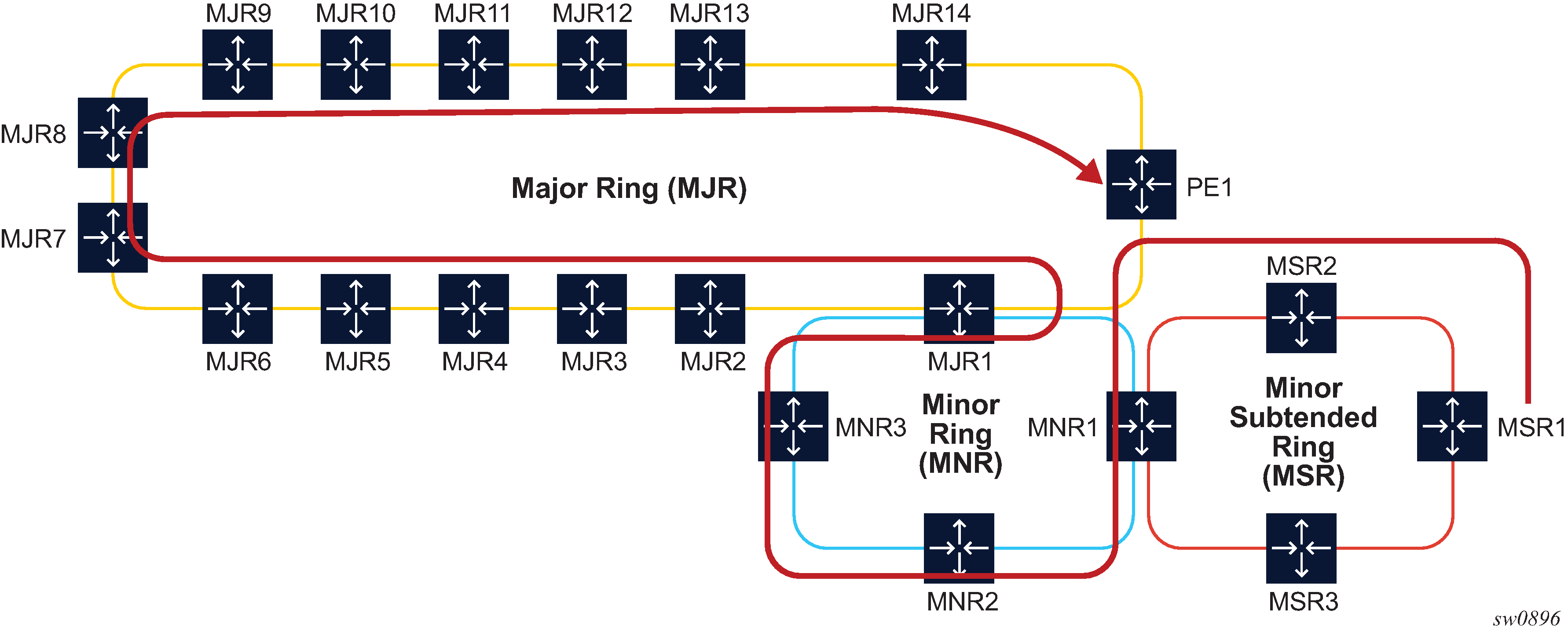
The path of the highlighted LSP uses admin groups to force the traffic eastwards or westwards over the 3-ring topologies such that it uses the longest path possible. Assume all links in the bottom-most ring1 have admin-group=east1 for the eastward direction and admin-group=west1 for the westward direction.
Similarly, links in the middle ring2 have admin-group=east2 and admin-group=west2, and links in the top-most ring3 have admin-group=east3 and admin-group=west3. To achieve the longest path shown, the LSP or path should have an include statement: include east1 west2 east3. The fully explicit path computed in Phase 1 of CSPF results in label stack of size 18.
The label stack reduction algorithm searches for the farthest node SID in that path, which can replace a segment of the strict path while maintaining the admin-group constraints. The reduced label stack contains the SID adjacency MSR1-MSR2, the found node SIDs plus the node SID of the destination for a total of four labels to be pushed on the packet (the label for the adjacency MSR1-MSR2 is not pushed):
{N-SID MNR2, N-SID of MNR3, N-SID of MJR8, N-SID of PE1}
The following figure shows a topology example that creates two TE planes by applying a common admin group to all links of a specified plane. There are a total of four ECMP paths to reach PE2 from PE1: two within the red plane and two within the blue plane.
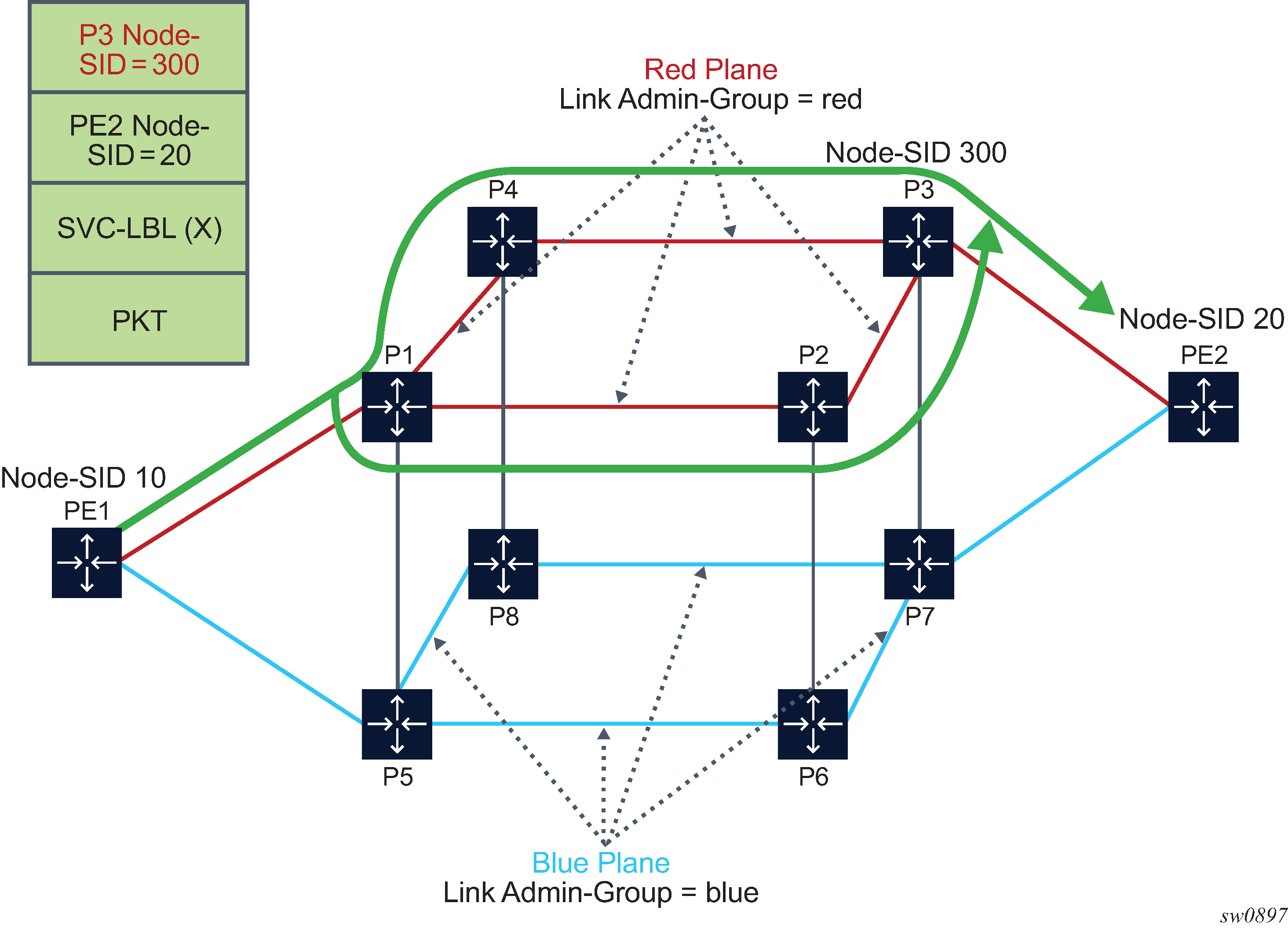
For an SR-TE LSP from PE1 to PE2, which includes the red admin group as a constraint, Phase 1 of CSPF results in two fully explicit paths using adjacency SID of the red TE links:
path 1 = {PE1-P1, P1-P2, P2-P3, P3-PE2}
path 2 = {PE1-P1, P1-P4, P4-P3, P3-PE2}
Phase 2 of CSPF finds node SID of P3 as the farthest hop it can reach directly from PE1 while still satisfying the constraint to include the red admin-group constraint. If the node SID of PE2 is used as the only SID, then traffic would also be sent over the blue links. The reduced label stack is:
{P3 Node-SID=300, PE2 Node-SID=20}.
The resulting SR-TE LSP path combines the two explicit paths from Phase 1 into a single path with ECMP support.
SR-TE LSP Paths Using Explicit SIDs
The 7705 SAR allows an explicit SID value to be configured for each hop in an SR-TE LSP path. The SID value for an SR-TE LSP hop is configured using the sid-label parameter under the config>router>mpls>path>hop context.
The sid-value parameter specifies an MPLS label value for that hop in the path.
The 7705 SAR supports a path computation method per LSP while allowing a mix-and-match configuration for primary and secondary paths. For example, primary and secondary paths can be different types: IP-to-hop paths or SID-based paths.
A path containing SID label hops is used even if the path computation method is configured at the LSP level. The path computation method is ignored and the router brings up the path configured with explicit SIDs.
When SIDs are explicitly configured for a path, the user must provide all of the necessary SIDs to reach the destination. The router does not validate whether the whole label stack provided is correct other than checking that the top SID is programmed locally. A path can come up even if it contains SIDs that are invalid. The user or controller programming the path should ensure that the SIDs are correct.
A path must consist of either all SIDs or all IP address hops.
Paths containing explicit SID values can only be used by SR-TE LSPs.
SR-TE LSP Protection
The router supports local protection of a particular segment of an SR-TE LSP and end-to-end protection of the complete SR-TE LSP.
Each path is locally protected along the network using LFA or remote-LFA next hop whenever possible. The protection of a node SID reuses the LFA and remote LFA features introduced with segment routing shortest path tunnels; the protection of an adjacency SID has been added to the 7705 SAR in the specific context of an SR-TE LSP to augment the protection level. The user must enable the loopfree-alternates>remote-lfa command in IS-IS or OSPF.
An SR-TE LSP has state at the ingress LER only. The LSR has state for the node SID and adjacency SID, whose labels are programmed in the label stack of the received packet and which represent the part of the ERO of the SR-TE LSP on this router and downstream of this router. In order to provide protection for an SR-TE LSP, each LSR node must attempt to program a link-protect or node-protect LFA next hop in the ILM record of a node SID or an adjacency SID, and the LER node must do the same in the LTN record of the SR-TE LSP. The following are details of the behavior.
If the ILM record is for a node SID of a downstream router that is not directly connected, the ILM of this node SID points to the backup NHLFE computed by the LFA SPF and programmed by the SR module for this node SID. Depending on the topology and LFA policy used, this can be a link-protect or node-protect LFA next hop.
This behavior is already supported in the SR shortest path tunnel feature at both the LER and LSR. Therefore, an SR-TE LSP that transits at an LSR and that matches the ILM of a downstream node SID automatically takes advantage of this protection when enabled. If required, node SID protection can be disabled under the IGP instance by excluding the prefix of the node SID from the LFA.
If the ILM is for a node SID of a directly connected router, the LFA SPF only provides link protection. The ILM or LTN record of this node SID points to the backup NHLFE of this LFA next hop. An SR-TE LSP that transits at an LSR and that matches the ILM of a neighboring node SID automatically takes advantage of this protection when enabled.
Note: Only link protection is possible in this case because packets matching this ILM record can either terminate on the neighboring router owning the node SID or can be forwarded to different next hops of the neighboring router, that is, to different next next-hops of the LSR providing the protection. The LSR providing the connection does not have context to distinguish among all possible SR-TE LSPs and therefore can only protect the link to the neighboring router.If the ILM or LTN record is for an adjacency SID, it is treated as in the case of a node SID of a directly connected router.
When protecting an adjacency SID, the PLR first tries to select a parallel link to the node SID of the directly connected neighbor. That is the case when the node SID is reachable over parallel links. The selection is based on lowest interface ID. If no parallel links exist, regular LFA/remote LFA algorithms are applied to find a loopfree path to reach the node SID of the neighbor via other neighbors.
The ILM or LTN for the adjacency SID must point to this backup NHLFE and will benefit from FRR link protection. As a result, an SR-TE LSP that transits at an LSR and matches the ILM of a local adjacency SID automatically takes advantage of this protection when enabled.
At the ingress LER, the LTN record points to the SR-TE LSP NHLFE, which points to the NHLFE of the SR shortest path tunnel to the node SID or adjacency SID of the first hop in the ERO of the SR-TE LSP. The FRR link or node protection at the ingress LER is inherited directly from the SR shortest path tunnel.
If an adjacency to a neighbor fails, the IGP withdraws the advertisement of the link TLV information as well as its adjacency SID sub-TLV. However, the LTN or ILM record of the adjacency SID must be kept in the data path for a sufficient period of time to allow the ingress LER to compute a new path after the IGP converges. If the adjacency is restored before the timer expires, the timer is aborted as soon as the new ILM or LTN records are updated with the new primary and backup NHLFE information. By default, the ILM/LTN and NHLFE information is kept for a period of 15 s.
The adjacency SID hold timer is configured using the adj-sid-hold command and activated when the adjacency to the neighbor fails due to the following conditions:
the network IP interface went down due to a link or port failure or due to the user performing a shutdown of the port
the user shuts down the network IP interface in the config>router or config>router>ospf/isis context
The adjacency SID hold timer is not activated if the user deletes an interface in the config>router>ospf/isis context.
The adjacency SID hold timer does not apply to the ILM or LTN of a node SID, because NHLFE information is updated in the data path as soon as the IGP is converged locally and a new primary and LFA backup next hops have been computed.
The label information of the primary path of the adjacency SID is maintained and reprogrammed if the adjacency is restored before the timer expires. However, the backup NHLFE may change when a new LFA SPF is run while the adjacency ILM is being held by the timer running. An update to the backup NHLFE is performed immediately following the LFA SPF and may cause packets to drop.
A new protect group ID (PG-ID) is assigned each time an adjacency comes back up. This PG-ID is used by the ILM of the adjacency SID and the ILMs of all downstream node SIDs that resolve to the same next hop.
While protection is enabled globally for all node SIDs and local adjacency SIDs when the user enables the loopfree-alternates command in IS-IS or OSPF at the LER and LSR, there are applications where the user wants traffic to never divert from the strict hop computed by CSPF for an SR-TE LSP. In that case, the user can disable protection for all adjacency SIDs formed over a particular network IP interface using the sid-protection command.
The protection state of an adjacency SID is advertised in the B-FLAG of the IS-IS or OSPF Adjacency SID sub-TLV. No mechanism exists in PCEP for the PCC to signal to the PCE the constraint to use only adjacency SIDs, which are not protected. The path profile ID is configured in the PCE with the no-protection constraint.
Local Protection
Each path can be locally protected through the network using LFA, remote LFA, or TI-LFA next hop whenever possible. The protection of a node SID reuses the LFA and remote LFA features introduced with SR shortest path tunnels. The protection of an adjacency SID has been added to the 7705 SAR in the specific context of an SR-TE LSP to augment the protection level. The user must enable the LFA, remote LFA, or TI-LFA option in IS-IS or OSPF.
This behavior is supported in the SR shortest path tunnel feature at both the LER and LSR. An SR-TE LSP that transits at an LSR and that matches the ILM of a downstream node SID automatically takes advantage of this protection when enabled. If required, node SID protection can be disabled under the IGP instance by excluding the prefix of the SID node from LFA.
End-to-End Protection
This section provides a brief introduction to end-to-end protection for SR-TE LSPs. See Seamless BFD for SR-TE LSPs for detailed information about protection switching using seamless BFD (S-BFD) and a configured failure action.
The 7705 SAR supports end-to-end protection for SR-TE LSPs using secondary or standby paths. Standby paths (secondary paths with standby enabled) are permanently programmed in the data path, while secondary paths are only programmed when they are activated. S-BFD is used for end-to-end connectivity checking. The failure-action failover-or-down command under the bfd context of the LSP configures a switchover from the currently active path to an available standby or secondary path if the S-BFD session fails on the currently active path. If S-BFD is not configured, the router that is local to a segment can only detect failures of the top SID for that segment.
End-to-end protection with S-BFD can be combined with local protection but it is recommended that the S-BFD control packet timers be set to a value high enough to allow sufficient time for any local protection action for a particular segment to complete without triggering S-BFD to go down on the end-to-end LSP path.
In order to prevent failures between the paths of an SR-TE LSP (for example, to prevent a failure of a primary path that affects its standby backup path), disjoint paths should be configured.
Seamless BFD for SR-TE LSPs
The 7705 SAR supports seamless BFD (S-BFD). Unlike LSP BFD, S-BFD does not rely on the traditional BFD session bootstrapping process or session state at the tail end of a session. Instead, when S-BFD is initialized the system selects a set of discriminators for the reflector or initiator function.
One S-BFD reflector is configured per system in the config>bfd>seamless-bfd context. A mapping between reflector discriminators and their IP addresses is configured on the initiator in the config>router>bfd>seamless-bfd context.
For information about seamless BFD, see the 7705 SAR Router Configuration Guide, Seamless BFD.
This section describes the application of S-BFD to SR-TE LSPs and the LSP configuration required for this feature.
S-BFD is supported in the following SR-TE contexts:
PCC-initiated:
SR-TE LSP level
SR-TE primary path
SR-TE secondary and standby paths
Configuration of S-BFD on SR-TE LSPs
For PCC-initiated or PCC-controlled LSPs, the head end of an S-BFD session is configured under the SR-TE LSP context, the SR-TE primary path context, or the SR-TE secondary path context by using the following commands:
config>router>mpls>lsp lsp-name sr-te>bfd
config>router>mpls>lsp lsp-name sr-te>primary>bfd
config>router>mpls>lsp lsp-name sr-te>secondary>bfd
The remote discriminator value is determined by passing the to address of the LSP to BFD, which then matches it to a mapping table of peer IP addresses to reflector remote discriminators. If there is no match for the to address of the LSP, a BFD session is not established on the LSP or path.
The referenced BFD template must specify parameters that are consistent with an S-BFD session; for example, the endpoint type must be np.
S-BFD can be configured at the LSP level, as follows:
configure>router>mpls>lsp <name> sr-te
      bfd
        [no] bfd-enable
        [no] bfd-template
        [no] failure-action
        [no] wait-for-up-timer <seconds>
        exit
When S-BFD is configured at the LSP level, separate S-BFD sessions with the same configuration are enabled on all primary, secondary, and standby paths of the LSP.
Alternatively, S-BFD can be configured on the primary path or secondary path of the LSP, as follows:
configure>router>mpls>lsp <name> sr-te
   primary <name>
      bfd
        [no] bfd-enable
        [no] bfd-template <name>
        [no] wait-for-up-timer <seconds>
        exit
configure>router>mpls>lsp <name> sr-te
   secondary <name>
      bfd
        [no] bfd-enable
        [no] bfd-template <name>
        [no] wait-for-up-timer <seconds>
        exit
      standby
The wait-for-up-timer command only applies if the configured failure action is failover-or-down. For more information, see Support for BFD Failure Action with SR-TE LSPs.
Support for BFD Failure Action with SR-TE LSPs
S-BFD provides a mechanism to check the data path forwarding for an SR-TE LSP. If an S-BFD session fails, the LSP can be brought operationally down when the failure-action command is configured with the failover-or-down option. When the failure-action command is not configured, an S-BFD failure will only raise a trap. The failure-action command is available in the following context:
configure>router>mpls
   lsp <name> sr-te
      bfd
        failure-action failover-or-down
        no failure-action
The failure-action command is configured at the LSP level. It can be configured whether S-BFD is applied at the LSP level or the individual path level. The failure-action command can be configured even if the BFD template is not yet configured.
For LSPs configured with a primary path and a secondary or standby path and a failure action of failover-or-down, the following points apply.
The path is held in an operationally down state when its S-BFD session is down.
If all paths are operationally down, the SR-TE LSP is taken operationally down and a trap is generated.
If S-BFD is enabled at the LSP or active path level, a switchover from the active path to an available path is triggered if the S-BFD session fails on the active path (primary or standby).
If S-BFD is not enabled on the active path and this path is shut down, a switchover is triggered.
If S-BFD is enabled on the candidate standby or secondary path, this path is only selected if S-BFD is up.
An inactive standby path configured with S-BFD is only available to become active if it is not operationally down; that is, its S-BFD session is up and all other criteria for it to become operational are true. The path is held in an inactive state if the S-BFD session is down.
The system does not revert to the primary path or start a reversion timer when the primary path is either administratively down or operationally down, because the S-BFD session is not up or down for any other reason.
For LSPs configured with only one path and a failure action of failover-or-down, the following points apply.
The path is held in an operationally down state when its S-BFD session is down.
If the path is operationally down, the LSP is taken operationally down and a trap is generated.
Note: S-BFD packets can still be sent on an operationally down SR-TE LSP.
For LSPs configured with one or more paths but no configured failure action, a BFD trap is raised when the LSP goes down. The path state does not change.
SR-TE LSP State Changes and Failure Actions Based on S-BFD
When a path is first configured with S-BFD, it is held operationally down until BFD comes up (subject to the BFD wait time).
The BFD wait-for-up-timer is started when BFD is first enabled on a path or when an existing S-BFD session transitions from up to down. If this timer expires before S-BFD is up, the path is torn down and the LSP retry timer is started.
In the S-BFD up-to-down case, if there is only one path, the LSP is torn down when S-BFD fails and then deprogrammed when the wait-for-up-timer expires.
If all the paths of an LSP are operationally down due to S-BFD, the LSP is taken operationally down and the BFD wait-for-up-timer is started for each path. If one or more paths do not have S-BFD configured or are otherwise not down, the LSP is not taken operationally down.
When an existing S-BFD session fails on a path and the failure action is failover-or-down, the configured failure action is activated, the path is put into the operationally down state, and a trap is raised. The state and reason code are displayed with the show>router>bfd>seamless-bfd command.
S-BFD Operational Considerations
A minimum control packet timer transmit interval of 10 ms can be configured. To maximize the reliability of S-BFD connectivity checking in scaled scenarios with short timers, situations where BFD may go down due to normal changes of the next hop of an LSP path at the head end must be avoided. It is therefore recommended that LFA not be configured at the head-end LER when using S-BFD with sub-second timers. When LFA is not configured, protection of the SR-TE LSP is still provided end-to-end by the combination of S-BFD connectivity checking and primary or secondary path protection.
Similar to LDP and RSVP functionality, S-BFD uses a single path for a loose hop; multiple S-BFD sessions for each of the ECMP paths or spraying of S-BFD packets across the paths is not supported. S-BFD is not down until all the ECMP paths of the loose hop go down.
Static Route Resolution Using SR-TE LSPs
Static route packets can be forwarded to an indirect next hop over an SR-TE LSP programmed in the TTM with the following static route tunnel binding command:
- CLI Syntax:
config>router>static-route-entry ip-prefix/prefix-length [mcast]indirect ip-addresstunnel-next-hopresolution {any | disabled | filter}resolution-filter[no] sr-te[no] lsp lsp-nameexitexitexitexit
BGP Label Route Resolution Using SR-TE LSPs
An SR-TE LSP programmed in the TTM can be used for resolving the next hop of a BGP IPv4 label route with the following BGP transport tunnel command:
- CLI Syntax:
config>router>bgp>next-hop-res>label-route-transport-tunnel[no] family {label-ipv4 | vpn}resolution {any | disabled | filter}resolution-filter[no] sr-teexitexitexit
Service Packet Forwarding Using SR-TE LSPs
An SDP sub-type of the MPLS encapsulation type allows service binding of up to eight SR-TE LSPs programmed in the TTM by MPLS. The following example shows how to bind an SR-TE LSP to an MPLS SDP:
- Example:
configure service sdp 100 mpls createconfig>service>sdp$ sr-te-lsp lsp-name
The destination address of all LSPs must match the SDP far-end address. Service data packets are sprayed over the set of LSPs in the SDP using the same procedures as for tunnel selection in ECMP. In all cases, the SDP can only spray packets over a maximum of eight next hops. Each SR-TE LSP can, however, have up to eight next hops at the ingress LER when the first segment is a node SID-based SR tunnel. The SDP selects one next hop from each SR-TE LSP until the maximum number of eight next hops for the SDP is reached.
The tunnel-far-end option is not supported. In addition, the mixed-lsp-mode option does not support the sr-te tunnel type.
The signaling protocol for the service labels for an SDP using an SR-TE LSP can be configured to static (off), T-LDP (tldp), or BGP (bgp).
An SR-TE LSP can be used in VPRN auto-bind with the following commands:
- CLI Syntax:
config>service>vprn>auto-bind-tunnelresolution {any | disabled | filter}resolution-filter[no] sr-teexitexit
Both VPN-IPv4 and VPN-IPv6 (6VPE) are supported in a VPRN service using segment routing transport tunnels with the auto-bind-tunnel command.
This auto-bind-tunnel command is also supported with BGP EVPN service, as shown below:
- CLI Syntax:
config>service>vpls>bgp-evpn>mpls>auto-bind-tunnelresolution {any | disabled | filter}resolution-filter[no] sr-teexitexit
The following service contexts are supported with SR-TE LSPs:
VLL, VPLS, IES/VPRN spoke SDP and interface, and r-VPLS
Epipe and VPLS services under BGP EVPN
intra-AS BGP VPRN for VPN-IPv4 and VPN-IPv6 prefixes with both auto-bind and explicit SDP
inter-AS option C for VPN-IPv4 and VPN-IPv6 VPRN prefix resolution
multicast over IES/VPRN spoke interface with spoke SDP over an SR-TE LSP
Data Path Support
The support of SR-TE in the data path requires that the ingress LER push a label stack where each label represents a hop, a TE link, or a node, in the ERO for the LSP path computed by the router or the PCE. However, only the label and the outgoing interface to the first strict or loose hop in the ERO factor into the forwarding decision of the ingress LER. In other words, the SR-TE LSP only needs to track the reachability of the first strict or loose hop.
The first strict or loose hop of the SR-TE LSP is represented as an NHFLE to the SR shortest path tunnel. The rest of the SR-TE label stack can have a larger size and is modeled as another NHLFE referred to as a ‟super NHLFE”.
Therefore, an SR-TE LSP is modeled in the ingress LER data path as a hierarchical LSP with the super NHLFE tunneled over the NHLFE of the SR shortest path tunnel to the first strict or loose hop in the SR-TE LSP path ERO.
Some characteristics of this design are as follows.
The design saves on NHLFE usage. When many SR TE LSPs are going to the same first hop, they will be using the same SR shortest path tunnel and will consume one super NHLFE each, but they will be pointing to a single NHLFE, or set of NHLFEs, when ECMP exists for the first strict or loose hop, of the first-hop SR tunnel.
The ingress LER does not need to program a separate backup super NHLFE. Instead, the single super NHLFE will automatically begin forwarding packets over the LFA backup path of the SR tunnel to the first hop as soon as it is activated.
There is an exception to the above model in the case where the user configured an empty path SR-TE LSP that uses the router’s hop-to-label translation. In this case, the SR-TE LSP will use the NHLFE of the node SID of the destination router. The super NHLFE is null in this case.
If the first segment is a node SID tunnel and multiple next hops exist, ECMP spraying is supported at the ingress LER.
If the first-hop SR tunnel, node SID, or adjacency SID goes down, the SR module informs MPLS that the outer tunnel is down and MPLS brings the SR-TE LSP down and requests the SR to delete the SR-TE LSP in the IOM.
The data path behavior at the LSR and egress LER for an SR-TE LSP is similar to that of the shortest path tunnel because there is no tunnel state in these nodes. The forwarding of the packet is based on processing the incoming label stack consisting of a node SID and/or adjacency SID label. If the ILM is for a node SID and multiple next hops exist, ECMP spraying is supported at the LSR.
The link-protect LFA backup next hop for an adjacency SID can be programmed at the ingress LER and LSR nodes (as explained in SR-TE LSP Protection).
A maximum of 12 labels, including all transport (including entropy), service, NGE, and OAM labels, can be pushed. The label stack size for the SR-TE LSP can be 1 to 11 labels, with a default value of 6.
The label stack size manipulation includes the following LER and LSR roles:
LER role:
push up to 12 labels depending on the service type
pop up to 8 labels
LSR role:
pop up to 5 labels and swap 1 label for a total of 6 labels
LSR hash of a packet with up to 10 labels
An example of the label stack pushed by the ingress LER and by an LSR acting as a PLR is illustrated in SR-TE LSP Label Stack Programming.
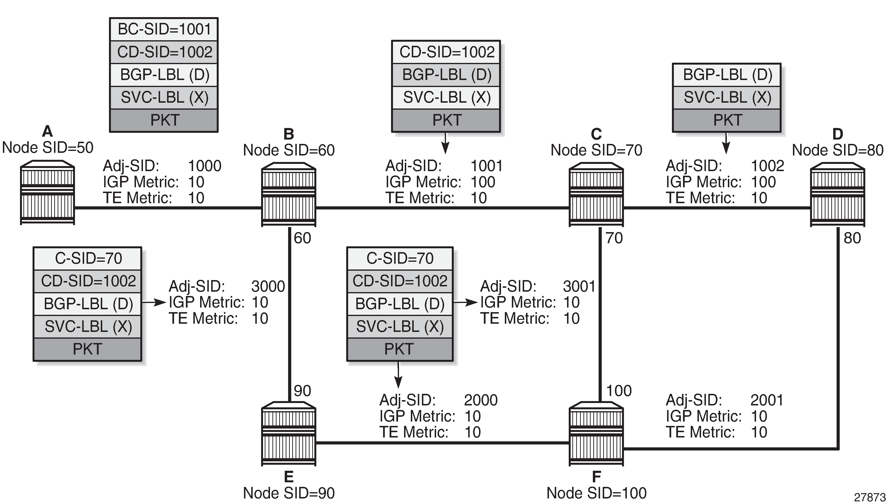
On node A, the user configures an SR-TE LSP to node D with a list of explicit strict hops mapping to the adjacency SID of links A-B, B-C, and C-D.
Ingress LER A programs a super NHLFE consisting of the label for the adjacency over link C-D and points it to the already programmed NHLFE of the SR tunnel of its local adjacency over link A-B. The latter NHLFE has the top label and also the outgoing interface to send the packet to.
LSR Node B already programmed the primary NHLFE for the adjacency SID over link C-D and has the ILM with label 1001 point to it. In addition, node B will preprogram the link-protect LFA backup next hop for link B-C and point the same ILM to it.
VPRN service in node A forwards a packet to the VPN-IPv4 prefix X advertised by BGP peer D. SR-TE LSP Label Stack Programming shows the resulting data path at each node for the primary path and for the FRR backup path at LSR B.
SR-TE LSP Metric and MTU Settings
The MPLS module assigns an SR-TE LSP the maximum LSP metric value of 16 777 215 when the local router provides the hop-to-label translation for its path. For an SR-TE LSP that uses local CSPF or PCE for path computation or has its control delegated to the PCE (pce-control enabled), the latter will return the computed LSP IGP or TE metric in the PCReq and PCUpd messages. In all cases, the user can override the returned value by configuring an admin metric using the command config>router>mpls>lsp>metric.
The MTU setting of an SR-TE LSP is derived from the MTU of the outgoing SR shortest path tunnel it is using, adjusted with the size of the super NHLFE label stack size.
The following are the details of this calculation:
SR_Tunnel_MTU = MIN {Cfg_SR_MTU, IGP_Tunnel_MTU – (1+ frr-overhead)✕4}
where:
Cfg_SR_MTU is the MTU configured by the user for all SR tunnels within a particular IGP instance using config>router>ospf/isis>segment-routing>tunnel-mtu. If no value was configured by the user, the SR tunnel MTU will be fully determined by the IGP interface calculation. This calculation is performed by the IGP and passed to the SR module each time it changes due to an updated resolution of the node SID.
IGP_Tunnel_MTU is the minimum of the IS-IS or OSPF interface MTU among all the ECMP paths or among the primary and LFA backup paths of this SR tunnel.
frr-overhead is set to 1 if segment-routing and remote-lfa options are enabled in the IGP instance; otherwise, it is set to 0.
This calculation is performed by the IGP and passed to the SR module each time it changes due to an updated resolution of the node SID.
The 7705 SAR also provides the MTU for the adjacency SID tunnel because it is needed in an SR-TE LSP if the first hop in the ERO is an adjacency SID. In that case, the calculation for SR_Tunnel_MTU, initially introduced for a node SID tunnel, is applied to get the MTU of the adjacency SID tunnel.
The MTU of the SR-TE LSP is derived as follows:
SRTE_LSP_MTU = SR_Tunnel_MTU – numLabels✕4
where:
SR_Tunnel_MTU is the MTU SR tunnel shortest path that the SR-TE LSP is using. The 7705 SAR also provides the MTU for the adjacency SID tunnel because it is needed in an SR-TE LSP if the first hop in the ERO is an adjacency SID. In that case, the calculation for SR_Tunnel_MTU (given above), initially introduced for a node SID tunnel, is applied to get the MTU of the adjacency SID tunnel.
numLabels is the number of labels found in the super NHLFE of the SR-TE LSP. At LER, the super NHLFE is pointing to the SR tunnel NHLFE, which has a primary and a backup NHLFE.
This calculation is performed by the SR module and is updated each time the SR-TE LSP path changes or the SR tunnel it is using is updated.
SR-TE Entropy Labels
The 7705 SAR supports SR-TE entropy labels as described in MPLS Entropy Labels.
Weighted ECMP by RSVP-TE or SR-TE LSPs
ECMP over MPLS LSPs implements packet spraying across multiple RSVP-TE or SR-TE LSPs within the same ECMP set.
ECMP RSVP-TE or SR-TE packet spraying consists of hashing the relevant fields in the header of a labeled packet and selecting the next-hop tunnel based on the modulo operation of the output of the hash and the number of ECMP tunnels. The maximum number of ECMP tunnels selected from the Tunnel Table Manager (TTM) matches the value of the user-configured ecmp command. Only LSPs with the same lowest LSP metric can be part of the ECMP set. If the number of these LSPs is higher than the value configured with the ecmp command, the LSPs with the lowest tunnel IDs are selected first.
The ecmp command context for setting the number of routes that are used on a service is as follows:
for VPRN auto-bind weighted ECMP: config>service>vprn>auto-bind-tunnel>ecmp max-ecmp-routes
for OSPF PE-CE weighted ECMP: config>service>vprn>ecmp max-ecmp-routes
for VPN route-reflector forwarding with next-hop-self: config>router>ecmp max-ecmp-routes
for weighted ECMP for SDPs: the number of LSPs specified in the command config>service>sdp>lsp lspx lspy lspz or config>service>sdp>sr-te-lsp lspx lspy lspz
for EVPN auto-bind weighted ECMP: config>service>epipe>bgp-evpn>mpls>auto-bind-tunnel>ecmp max-ecmp-routes or config>service>vpls>bgp-evpn>mpls>auto-bind-tunnel>ecmp max-ecmp-routes
With the weighted ECMP functionality, the load-balancing weight of the LSP is normalized by the system and then used to bias the amount of traffic forwarded over each LSP.
Weighted ECMP is supported on the following services:
VPRN with auto-bind tunnels
EVPN-VPWS and EVPN-VPLS with auto-bind tunnels
IES and VPRN Layer 3 spoke-SDP terminated interfaces
Epipe services with spoke SDPs
Ipipe services with spoke SDPs
VPLS services with spoke or mesh SDPs
VPRN OSPF PE-CE interfaces
The weight of the LSP is configured using the config>router>mpls>lsp>load-balancing-weight weight and config>router>mpls>lsp-template>load-balancing-weight weight commands.
Weighted ECMP for VPRN Services with Auto-bind
Weighted ECMP for VPRN services with auto-bind is enabled using the config>service>vprn>auto-bind-tunnel>weighted-ecmp command. This command is applicable if the auto-bind tunnel is configured for RSVP or SR-TE using the config>service>vprn>auto-bind-tunnel>resolution-filter>rsvp/sr-te command.
If weighted ECMP is enabled, a path is selected based on the output of the configured hashing algorithm. Packet paths are then mapped to LSPs for the service in proportion to the configured load-balancing weight of the LSP. The hash is based on the system load-balancing configuration. Weighted ECMP is disabled by default.
If an LSP in the ECMP set has no load-balancing weight configured, and the ECMP is set to a specific next hop, regular ECMP spraying is used.
Weighted ECMP for EVPN
ECMP for Layer 2 unicast traffic on Epipe and VPLS services for EVPN-MPLS destinations is enabled using the config>service>epipe>bgp-evpn>mpls>auto-bind-tunnel>ecmp command or config>service>vpls>bgp-evpn>mpls>auto-bind-tunnel>ecmp command. These commands allow the resolution of an EVPN-MPLS next hop to a group of ECMP tunnels of type RSVP-TE or SR-TE.
Weighted ECMP is enabled using the config>service>epipe>bgp-evpn>mpls> auto-bind-tunnel>weighted-ecmp command or config>service>vpls>bgp-evpn>mpls>auto-bind-tunnel>weighted-ecmp command. These commands allow packets to be sprayed across LSPs in the ECMP set according to the outcome of the hash algorithm and the configured load-balancing weight of each LSP.
EVPN VPWS ECMP and weighted ECMP behave like a non-EVPN Layer 2 Epipe and perform per-service ID hashing.
EVPN VPLS ECMP and weighted ECMP behave like a non-EVPN Layer 2 VPLS and perform per-service ID hashing but also include an internal egress ID.
Weighted ECMP for SDPs
Weighted ECMP for IES or VPRN Layer 3 spoke SDP interfaces, Epipe and Ipipe services with SDPs, and VPLS services with spoke or mesh SDPs is enabled using the config>service>sdp>weighted-ecmp command. This command is applicable when the SDP has RSVP-TE LSPs configured using the config>service>sdp>lsp command or SR-TE LSPs configured using the config>service>sdp>sr-te-lsp command.
When weighted ECMP is enabled on an SDP, a path is selected based on the configured hash. Paths are then load-balanced across the LSPs used by the SDP according to the normalized LSP load-balancing weight configured using the load-balancing-weight command. This means that consecutive packets of a particular service use the same LSP, but the overall load handled by LSPs to the SDP far end is balanced according to the load-balancing weight if all services using the SDP send the same bandwidth and there are more services using the SDP than there are LSPs for the SDP.
If an LSP in the ECMP set has no load-balancing weight configured, ECMP is applied to packets based on the output of the hash for the service ID.
MPLS Service Usage
The 7705 SAR routers enable service providers to deliver virtual private networks (VPNs) and Internet access using Generic Routing Encapsulation (GRE), IP, and/or MPLS tunnels, with Ethernet and/or SONET/SDH interfaces.
Service Destination Points
A service destination point (SDP) acts as a logical way of directing traffic from one 7705 SAR router to another through a unidirectional (one-way) service tunnel. The SDP terminates at the far-end 7705 SAR router, which directs packets to the correct service egress service access point (SAP) on that device. All services mapped to an SDP use the GRE, IP, or MPLS transport encapsulation type.
For information about service transport tunnels, see the 7705 SAR Services Guide. Service transport tunnels can support up to eight forwarding classes and can be used by multiple services.
MPLS and RSVP-TE Configuration Process Overview
MPLS and RSVP-TE Configuration and Implementation Flow displays the process to configure MPLS and RSVP-TE parameters.
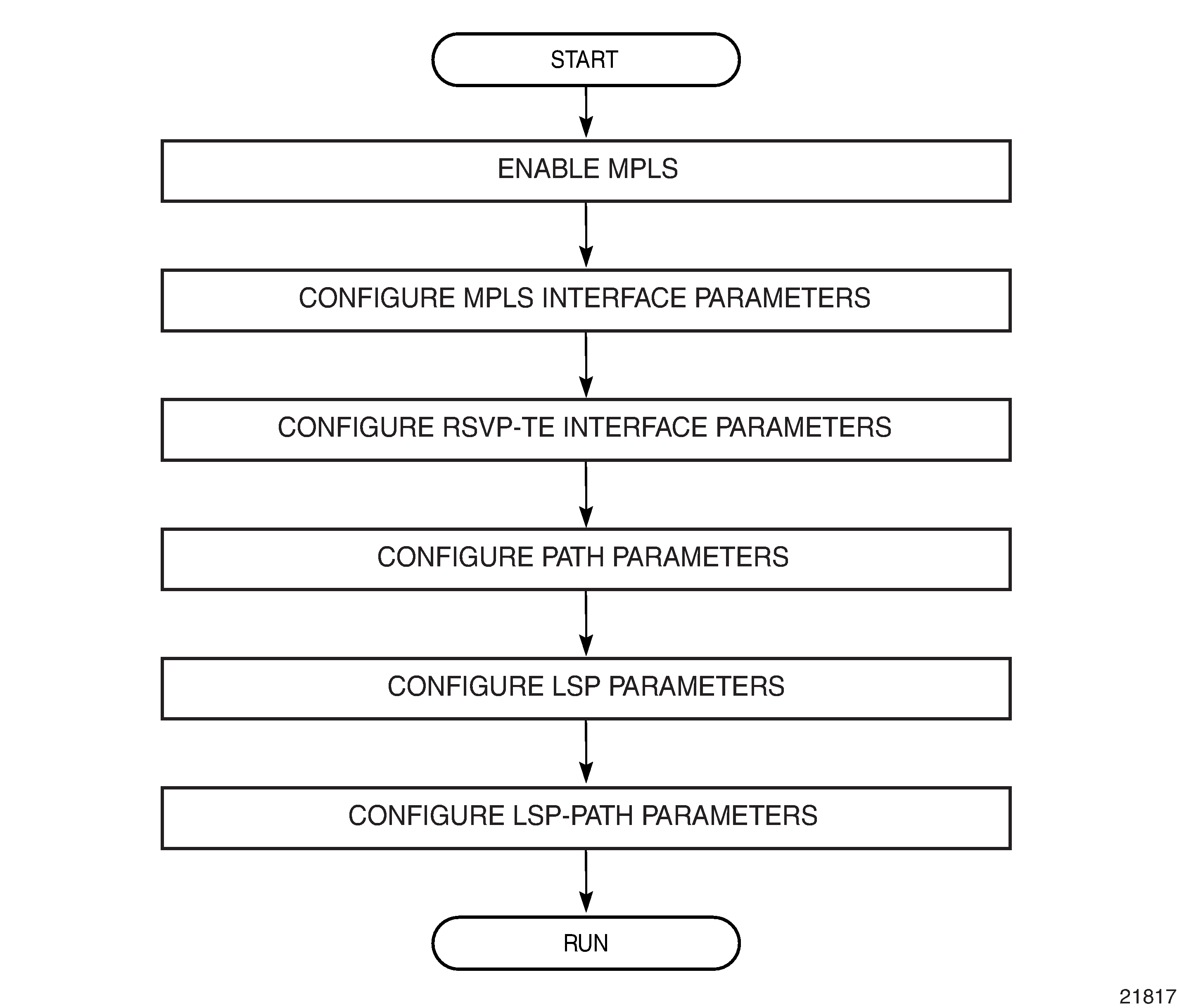
Configuration Notes
Network and system interfaces must be configured in the config>router>interface context before they can be specified in MPLS. See the 7705 SAR Router Configuration Guide for interface configuration information.
This section describes MPLS and RSVP-TE guidelines and caveats.
Interfaces must already be configured in the config>router>interface context before they can be specified in MPLS and RSVP.
A router interface must be specified in the config>router>mpls context in order to apply it or modify parameters in the config>router>rsvp context.
A system interface must be configured and specified in the config>router>mpls context.
Paths must be created before they can be applied to an LSP.
CSPF must be enabled in order for administrative groups and SRLGs to be relevant.
Configuring MPLS and RSVP-TE with CLI
This section provides information to configure MPLS and RSVP-TE using the CLI.
Topics in this section include:
MPLS Configuration Overview
MPLS enables routers to forward traffic based on a label embedded in the packet header. A router examines the label to determine the next hop for the packet, instead of router address lookups to the next node when forwarding packets.
To implement MPLS on an LSP for outer tunnel and pseudowire assignment, the following entities must be configured:
Signaling Protocol (for RSVP-TE or LDP)
Router Interface
At least one router interface and one system interface must be defined in the config>router>interface context in order to configure MPLS on an interface.
E-LSP for Differentiated Services
An EXP-inferred LSP (E-LSP) is an LSP that can support a variety of VLLs or traffic types. Up to eight types of traffic can be multiplexed over an E-LSP.
The prioritization of mission-critical traffic is handled by the settings of the three EXP bits. The EXP bits designate the importance of a particular packet. The classification and queuing at the Provider (P) or Provider Edge (PE) nodes typically take place based on the value of the EXP bits. See the 7705 SAR Quality of Service Guide for more information about the use of EXP bits and differentiated services on the 7705 SAR.
Paths
To configure signaled LSPs, you must first create one or more named paths on the ingress router using the config>router>mpls>path command. For each path, the transit routers (hops) in the path are specified.
LSPs
The 7705 SAR supports static and dynamic LSPs.
To configure MPLS-signaled (dynamic) LSPs, the LSP must run from an ingress LER to an egress LER. Configure the dynamic LSP only at the ingress router, and either configure the LSP to allow the router software to make the forwarding decisions or configure some or all routers in the LSP path statically. The LSP is set up by RSVP-TE signaling messages. The 7705 SAR automatically manages label values. Labels that are automatically assigned have values ranging from 1024 through 1 048 575 (see Label Values).
A static LSP is a manually configured LSP where the next hop IP address and the outgoing label are explicitly specified.
To establish a static LSP, an LSP must be configured from an ingress LER to an egress LER. Labels must be manually assigned and the label values must be within the range of 32 to 1023 (see Label Values).
Pseudowires
To configure PW/VLL labels, the PW/VLL service must be configured. PW/VLL labels can be configured manually as statically allocated labels using any unused label within the static label range. Pseudowire/VLL labels can also be dynamically assigned by targeted LDP. Statically allocated labels and dynamically allocated labels are designated differently in the label information base.
PW/VLL labels are uniquely identified against a 7705 SAR, not against an interface or module.
As defined in RFC 3036, LDP Specification, and RFC 4447 Pseudowire Setup and Maintenance Using the Label Distribution Protocol (LDP), label distribution is handled in the Downstream Unsolicited (DU) mode. Generic Label TLV is used for all setup and maintenance operations.
Signaling Protocol
For static LSPs, the path and the label mappings and actions configured at each hop must be specified manually. RSVP-TE or LDP is not required for static LSPs.
For dynamic LSPs, RSVP-TE or LDP must be turned on. See RSVP and RSVP-TE or Label Distribution Protocol.
To implement dynamic pseudowire/VLL labels, entities must be enabled as follows:
-
MPLS must be enabled on all routers that are part of a static LSP
-
LDP must be enabled on the ingress and egress LERs
When MPLS is enabled and either RSVP-TE or LDP is also enabled, MPLS uses RSVP-TE or LDP to set up the configured LSPs. For example, when you configure an LSP with both MPLS and RSVP-TE running, RSVP-TE initiates a session to create the LSP. RSVP-TE uses the local router as the RSVP-TE session sender and the LSP destination as the RSVP-TE session receiver. Once the RSVP-TE session is created, the LSP is set up on the path created by the session. If the session is not successfully created, RSVP-TE notifies MPLS; MPLS can then either initiate backup paths or retry the initial path.
Basic MPLS Configuration
This section provides information to configure MPLS and gives configuration examples of common configuration tasks. To enable MPLS on a 7705 SAR router, you must configure at least one MPLS interface. The MPLS interface is configured in the config>router> mpls context. The other MPLS configuration parameters are optional.
The following example displays an MPLS configuration output. The admin-group is configured in the config>router>if-attribute context and associated with the MPLS interface in the config>router>mpls>interface context.
A:ALU-1>config>router>if-attr# info
------------------------------------------
            admin-group "green" value 15
            admin-group "yellow" value 20
            admin-group "red" value 25
------------------------------------------
A:ALU-1>config>router>mpls# info
------------------------------------------
            interface "system"
            exit
            interface "StaticLabelPop"
                admin-group "green"
                label-map 50
                    pop
                    no shutdown
                exit
            exit
            interface "StaticLabelPop"
                label-map 35
                    swap 36 nexthop 10.10.10.91
                    no shutdown
                exit
            exit
            path "to-NYC"
                hop 1 10.10.10.104 strict
                no shutdown
            exit
            path "secondary-path"
                no shutdown
            exit
            lsp "lsp-to-eastcoast"
                to 10.10.10.104
                from 10.10.10.103
                fast-reroute one-to-one
                exit
                primary "to-NYC"
                exit
                secondary "secondary-path"
                exit
                no shutdown
            exit
            static-lsp "StaticLabelPush"
                to 10.10.11.105
                push 60 nexthop 10.10.11.105
                no shutdown
            exit
            no shutdown
Common Configuration Tasks
This section provides a brief overview of the tasks to configure MPLS and provides the CLI commands.
The following protocols must be enabled on each participating router:
MPLS
RSVP-TE (for RSVP-TE-signaled MPLS only)
LDP
In order for MPLS to run, you must configure at least one MPLS interface in the config>router>mpls context.
An interface must be created in the config>router>interface context before it can be applied to MPLS.
In the config>router>mpls context, configure the path parameters. A path specifies some or all hops from ingress to egress. A path can be used by multiple LSPs.
When an LSP is created, the egress router must be specified in the to command and at least one primary or secondary path must be specified. All other settings under the LSP hierarchy are optional.
Configuring MPLS Components
Use the MPLS and RSVP-TE CLI syntax shown in the following information for:
Configuring Global MPLS Parameters
Admin groups can signify link colors, such as red, yellow, or green, or some other link quality. Shared risk link groups (SRLGs) are lists of interfaces that share the same risk of failure due to shared resources. MPLS interfaces advertise the admin groups and SRLGs that they support. CSPF uses the information when paths are computed for constraint-based LSPs. CSPF must be enabled in order for admin groups and SRLGs to be relevant.
Admin groups and SRLGs are created in the config>router>if-attribute context. Other global parameters are created in the config>router>mpls context.
To configure global MPLS parameters, enter the following commands:
- CLI Syntax:
config>router>if-attributeadmin-group group-name value group-valuesrlg-group group-name value group-value
- CLI Syntax:
config>router>mplsbypass-resignal-timer minutesdynamic-bypass [enable | disable]frr-objecthold-timer secondsresignal-timer minutessrlg-frr [strict]
- Example:
config>router# if-attributeconfig>router>if-attr# admin-group ‟green” value 15config>router>if-attr# admin-group ‟red” value 25config>router>if-attr# admin-group ‟yellow” value 20config>router>if-attr# srlg-group ‟SRLG_fiber_1” value 50config>router>if-attr# exitconfig>router# mplsconfig>router>mpls# frr-objectconfig>router>mpls# bypass-resignal-timer 120config>router>mpls# hold-timer 3config>router>mpls# resignal-timer 500config>router>mpls# srlg-frr strict
The following example displays a global MPLS configuration output.
A:ALU-1>config>router>if-attr# info
----------------------------------------------
            admin-group "green" value 15
            admin-group "red" value 25
            admin-group "yellow" value 20
            srlg-group "SRLG_fiber_1" value 50
----------------------------------------------

A:ALU-1>config>router>mpls# info
----------------------------------------------
            frr-object
            bypass-resignal-timer 120
            hold-timer 3
            resignal-timer 500
            srlg-frr strict
----------------------------------------------
A:ALU-1>config>router>mpls# info
Configuring an MPLS Interface
The interface must exist in the system before it can be configured as an MPLS interface; see the 7705 SAR Router Configuration Guide for more information.
Once the MPLS protocol instance is created, the no shutdown command is not required since MPLS is administratively enabled upon creation. Configure the label-map parameters if the interface is used in a static LSP.
Use the following CLI syntax to configure an MPLS interface on a router:
- CLI Syntax:
config>router>mplsinterface ip-int-nameadmin-group group-name [group-name...(up to 5 max)]label-map in-labelpopswap out-label next-hop ip-addressno shutdownsrlg-group group-name [group-name...(up to 5 max)]te-metric valueno shutdown
- Example:
config>router# mplsconfig>router>mpls# interfaceto-104config>router>mpls>if# label-map35config>router>mpls>if>label-map# swap 36 next-hop 10.10.10.91config>router>mpls>if>label-map# no shutdownconfig>router>mpls>if>label-map# exitconfig>router>mpls>if#srlg-group ‟SRLG_fiber_1”config>router>mpls>if#no shutdownconfig>router>mpls# exit
The following example displays the interface configuration output.
A:ALU-1>config>router>mpls# info
----------------------------------------------
            interface "to-104"
                admin-group "green"
                admin-group "red"
                admin-group "yellow"
                label-map 35
                    swap 36 nexthop 10.10.10.91
                    no shutdown
                srlg-group "SRLG_fiber_1"
                exit
            exit
            no shutdown
Configuring MPLS Paths
When configuring an MPLS path for LSPs, the IP address of each hop that the LSP should traverse on its way to the egress router must be specified. The intermediate hops must be configured as either strict or loose, meaning that the LSP must take either a direct path from the previous hop router to this router (strict) or can traverse other routers (loose).
Use the following CLI syntax to configure a path:
- CLI Syntax:
config>router>mplspath path-namehop hop-index ip-address {strict|loose}no shutdown
The following example displays a path configuration output.
A:ALU-1>config>router>mpls# info
------------------------------------------
            interface "system"
            exit
            path "to-NYC"
                hop 1 10.10.10.103 strict
                hop 2 10.10.0.210 strict
                hop 3 10.10.0.215 loose
            exit
            path "secondary-path"
                hop 1 10.10.0.121 strict
                hop 2 10.10.0.145 strict
                hop 3 10.10.0.1 strict
                no shutdown
            exit
------------------------------------------
A:ALU-1>config>router>mpls#
Configuring an MPLS LSP
When configuring an LSP, you must specify the IP address of the egress router in the to statement. You must also specify the primary path to be used. Secondary paths can be explicitly configured or signaled upon the failure of the primary path. All other statements are optional.
The following displays an MPLS LSP configuration.
A:ALU-1>config>router>mplp# info
----------------------------------------------
...
            lsp "lsp-to-eastcoast"
                to 192.0.2.41
                rsvp-resv-style ff
                cspf
                include "red"
                exclude "green"
                adspec
                fast-reroute one-to-one
                exit
                primary "to-NYC"
                    hop-limit 10
                exit
                secondary "secondary-path"
                    bandwidth 50000
                exit
                no shutdown
            exit
            no shutdown
----------------------------------------------
A:ALU-1>config>router>mpls#
Configuring a Static LSP
An LSP can be explicitly (manually) configured. The reserved range of static LSP labels is 32 to 1023. Static LSPs are configured on every node along the LSP path. The label’s forwarding information includes the address of the next hop router.
Use the following CLI syntax to configure a static LSP:
- CLI Syntax:
config>router>mplsstatic-lsplsp-nametoip-addresspushlabelnexthopip-addressno shutdown
- Example:
config>router# mplsconfig>router>mpls# static-lspstatic-LSPconfig>router>mpls>static-lsp$ to10.10.10.124config>router>mpls>static-lsp# push60nexthop10.10.42.3config>router>mpls>static-lsp#no shutdownconfig>router>mpls>static-lsp# exit
The following example displays the static LSP configuration output.
ALU-1>config>router>mpls# info
----------------------------------------------
...
            static-lsp "static-LSP"
                to 10.10.10.124
                push 60 nexthop 10.10.42.3
                no shutdown
            exit
----------------------------------------------
Configuring a Fast-Retry Timer for Static LSPs
A fast-retry timer can be configured for static LSPs. When a static LSP is trying to come up, MPLS tries to resolve the ARP entry for the next hop of the LSP. This request may fail because the next hop might still be down or unavailable. In that case, MPLS starts a retry timer before making the next request. The fast-retry command allows the user to configure the retry timer so that the LSP comes up shortly after the next hop is available.
Use the following CLI syntax to configure a fast-retry timer for static LSPs:
- CLI Syntax:
config>router>mplsstatic-lsp-fast-retry seconds
- Example:
config>router# mplsconfig>router>mpls# static-lsp-fast-retry 15
Configuring Manual Bypass Tunnels
Consider the following network setup in Manual Bypass Tunnels. Assume that a manual bypass tunnel must be configured on Node B.
Disable dynamic bypass tunnels on Node B.
The CLI syntax for this configuration is:
config>router>mpls>dynamic-bypass [disable | enable]
By default, dynamic bypass tunnels are enabled.
Configure an LSP on Node B, such as B-E-F-C, which will be used only as a bypass. Specify each hop in the path and assign its strict or loose option; in this case, the bypass LSP will have a strict path. Designate the LSP as a primary LSP.
The CLI syntax for this configuration is:
config>router>mpls>path path-name >hop hop-index ip-address [strict | loose]
config>router>mpls>lsp lsp-name bypass-only
(see also the configuration example below)
Including the bypass-only keyword disables some options under the LSP configuration. See Disabled and Enabled Options for Bypass-Only.
Table 7. Disabled and Enabled Options for Bypass-Only Disabled Options
Enabled Options
bandwidth
fast-reroute
secondary
adaptive
adspec
cspf
exclude
hop-limit
include
metric
Configure an LSP from A to D and indicate fast-reroute bypass protection by selecting facility as the FRR method.
The CLI syntax for this configuration is:
config>router>mpls>lsp lsp-name>fast-reroute facility
If the LSP from A to D goes through Node B and bypass is requested, the next hop is Node C, and there is a manually configured bypass-only tunnel from B to C that excludes link BC (that is, path BEFC), then Node B uses the bypass-only tunnel.
The following example displays a bypass tunnel configuration output.
A:ALU-48>config>router>mpls># info
-------------------------------------------
...
            path "BEFC"
                hop 10 10.10.10.11 strict
                hop 10 10.10.10.12 strict
                hop 10 10.10.10.13 strict
                no shutdown
            exit
            lsp "bypass-BC" bypass-only
                to 10.10.10.15
                primary "BEFC"
                exit
                no shutdown
...
-------------------------------------------
Configuring RSVP-TE Parameters and Interfaces
RSVP-TE is used to set up LSPs. RSVP-TE must be enabled on the router interfaces that are participating in signaled LSPs. The default values can be modified in the config>router>rsvp context.
Initially, interfaces are configured in the config>router>mpls>interface context. Only these existing (MPLS) interfaces are available to be modified in the config>router>rsvp context. Interfaces cannot be directly added in the rsvp context.
The following example displays an RSVP-TE configuration output.
A:ALU-1>config>router>rsvp# info
----------------------------------------------
          keep-multiplier 3
          refresh-time 30
          no msg-pacing
          rapid-retransmit-time 5
          rapid-retry-limit 3
          refresh-reduction-over-bypass disable
          no graceful-shutdown
          no entropy-label-capability
          node-id-in-rro exclude
          interface "system"
             no shutdown
          exit
          interface to-104
             hello-interval 4000
             no shutdown
          exit
          no shutdown
----------------------------------------------
A:ALU-1>config>router>rsvp#
Configuring RSVP-TE Message Pacing Parameters
RSVP-TE message pacing maintains a count of the messages that were dropped because the output queue for the egress interface was full.
Use the following CLI syntax to configure RSVP-TE message pacing parameters:
- CLI Syntax:
config>router>rsvpno shutdownmsg-pacingperiod milli-secondsmax-burst number
The following example displays an RSVP-TE message pacing configuration output.
A:ALU-1>config>router>rsvp# info
----------------------------------------------
            keep-multiplier 5
            refresh-time 60
            msg-pacing
                period 400
                max-burst 400
            exit
            interface "system"
                no shutdown
            exit
            interface to-104
                hello-interval 4000
                no shutdown
            exit
            no shutdown
----------------------------------------------
A:ALU-1>config>router>rsvp#
MPLS Configuration Management Tasks
This section discusses the following MPLS configuration management tasks:
Deleting MPLS
The no form of the mpls command typically removes an MPLS instance and all associated information. However, MPLS must be disabled (shut down) and all SDP bindings to LSPs removed before an MPLS instance can be deleted. Once MPLS is shut down, the no mpls command deletes the protocol instance and removes all configuration parameters for the MPLS instance.
If MPLS is not shut down first, when the no mpls command is executed, a warning message on the console indicates that MPLS is still administratively up.
To delete the MPLS instance:
Disable the MPLS instance using the shutdown command.
Remove the MPLS instance from the router using the no mpls command.
- CLI Syntax:
config>router# no mpls
Modifying MPLS Parameters
Modifying an MPLS LSP
Some MPLS LSP parameters (such as primary and secondary), must be shut down before they can be edited or deleted from the configuration.
The following example displays an MPLS LSP configuration output. See Configuring an MPLS Interface.
A:ALU-1>>config>router>mpls>lsp# info
----------------------------------------------
                shutdown
                to 10.10.10.104
                from 10.10.10.103
                rsvp-resv-style ff
                include "red"
                exclude "green"
                fast-reroute one-to-one
                exit
                primary "to-NYC"
                    hop-limit 50
                exit
                secondary "secondary-path"
                exit
----------------------------------------------
A:ALU-1>config>router>mpls#
Modifying MPLS Path Parameters
To modify path parameters, the config>router>mpls>path context must be shut down first.
The following example displays an MPLS path configuration output. See Configuring MPLS Paths.
A:ALU-1>config>router>mpls# info
#------------------------------------------
echo "MPLS"
#------------------------------------------
...
            path "secondary-path"
                hop 1 10.10.0.111 strict
                hop 2 10.10.0.222 strict
                hop 3 10.10.0.123 strict
                no shutdown
            exit
            path "to-NYC"
                hop 1 10.10.10.104 strict
                hop 2 10.10.0.210 strict
                no shutdown
            exit
----------------------------------------------
Modifying MPLS Static LSP Parameters
Use the show>service>router>static-lsp command to display a list of LSPs.
To modify static LSP parameters, the config>router>mpls>static-lsp lsp-name context must be shut down.
To modify an LSP:
Access the specific LSP by specifying the LSP name, and then shut it down.
Enter the parameter to modify and then enter the new information.
- Example:
config>router# mplsconfig>router>mpls# static-lsp "static-LSP"config>router>mpls>static-lsp# shutdownconfig>router>mpls>static-lsp# to 10.10.0.234config>router>mpls>static-lsp# push 1023 nexthop 10.10.8.114config>router>mpls>static-lsp#no shutdownconfig>router>mpls>static-lsp# exit
The following example displays the static LSP configuration output.
ALU-1>config>router>mpls# info
----------------------------------------------
...
            static-lsp "static-LSP"
                to 10.10.10.234
                push 1023 nexthop 10.10.8.114
                no shutdown
            exit
            no shutdown
----------------------------------------------
ALU-1>config>router>mpls#
Deleting an MPLS Interface
To delete an interface from the MPLS configuration:
Administratively disable the interface using the shutdown command.
Delete the interface with the no interface command.
- CLI Syntax:
mplsinterface ip-int-nameshutdownexitno interface ip-int-name
- Example:
config>router# mplsconfig>router>mpls# interface to-104config>router>mpls>if# shutdownconfig>router>mpls>if# exitconfig>router>mpls# no interface to-104
The following example displays the configuration output when interface ‟to-104” has been deleted.
A:ALU-1>config>router>mpls# info
----------------------------------------------
...
admin-group "green" 15
            admin-group "red" 25
            admin-group "yellow" 20
            interface "system"
            exit
            no shutdown
----------------------------------------------
A:ALU-1>config>router>mpls#
RSVP-TE Configuration Management Tasks
This section discusses the following RSVP-TE configuration management tasks:
Modifying RSVP-TE Parameters
Only interfaces configured in the MPLS context can be modified in the rsvp context.
The no rsvp command deletes this RSVP-TE protocol instance and removes all configuration parameters for this RSVP-TE instance. The shutdown command suspends the execution and maintains the existing configuration.
The following example displays a modified RSVP-TE configuration output.
A:ALU-1>config>router>rsvp# info
----------------------------------------------
            keep-multiplier 5
            refresh-time 60
            msg-pacing
                period 400
                max-burst 400
            exit
            rapid-retransmit-time 5
            rapid-retry-limit 3
            refresh-reduction-over-bypass disable
            no graceful-shutdown
            no entropy-label-capability
            no implicit-null-label
            node-id-in-rro exclude
            interface "system"
            exit
            interface "test1"
                hello-interval 5000
            exit
            no shutdown
----------------------------------------------
A:ALU-1>config>router>rsvp#
Modifying RSVP-TE Message Pacing Parameters
RSVP-TE message pacing maintains a count of the messages that were dropped because the output queue for the egress interface was full.
The following example displays a modified RSVP-TE message pacing configuration output. See Configuring RSVP-TE Message Pacing Parameters.
A:ALU-1>config>router>rsvp# info
----------------------------------------------
            keep-multiplier 5
            refresh-time 60
            msg-pacing
                period 200
                max-burst 200
            exit
            interface "system"
            exit
            interface "to-104"
            exit
            no shutdown
----------------------------------------------
A:ALU-1>config>router>rsvp#
Deleting an Interface from RSVP-TE
Interfaces cannot be deleted directly from the RSVP-TE configuration. Because an interface is created in the mpls context and then configured in the rsvp context, it can only be deleted in the mpls context This removes the association from RSVP-TE.
Configuring and Operating SR-TE
This section provides information about the configuration and operation of the Segment Routing with Traffic Engineering (SR-TE) LSP. It covers the following topics:
SR-TE Configuration Prerequisites
To configure SR-TE, the user must first configure the prerequisite parameters.
First, configure the label space partition for the Segment Routing Global Block (SRGB) for all participating routers in the segment routing domain by using the mpls-labels>sr-labels command.
- Example:
configure>router>mpls-labelssr-labels start 200000 end 200400exit
Enable segment routing, traffic engineering, and advertisement of router capability in all participating IGP instances in all participating routers by using the traffic-engineering, advertise-router-capability, and segment-routing commands.
- Example:
ospf 0traffic-engineeringadvertise-router-capability arealoopfree-alternates remote-lfaarea 0.0.0.202stubno summariesexitinterface "system"node-sid index 194no shutdownexitinterface "toSim199"interface-type point-to-pointno shutdownexitinterface "toSim213"interface-type point-to-pointno shutdownexitinterface "toSim219"interface-type point-to-pointmetric 2000no shutdownexitexitsegment-routingprefix-sid-range globalentropy-label {force-disable | enable}no shutdownexitno shutdownexit
Configure a segment routing tunnel MTU for the IGP instance, if required, by using the tunnel-mtu command.
- Example:
prefix-sid-range globaltunnel-mtu 1500no shutdown
Assign a node SID to each loopback interface that a router would use as the destination of a segment routing tunnel by using the node-sid command.
- Example:
ospf 0area 0.0.0.202interface "system"node-sid index 194no shutdownexit
SR-TE LSP Configuration Overview
An SR-TE LSP can be configured as an LSP using the existing CLI command hierarchy under the MPLS context and specifying the sr-te LSP type.
- CLI Syntax:
config>router>mpls>lsp lsp-name | sr-te
A primary path can be configured for the SR-TE LSP.
Use the following CLI syntax to associate an empty path or a path with strict or loose explicit hops with the primary paths of the SR-TE LSP:
- CLI Syntax:
config>router>mpls>path>hop hop-index ip-address {strict | loose}config>router>mpls>lsp>primary path-name
Configuring Path Computation and Control for SR-TE LSPs
Use the following syntax to configure the path computation requests only (PCE-computed) or both path computation requests and path updates (PCE-controlled) to the PCE for a specific LSP:
- CLI Syntax:
config>router>mpls>lsp>path-computation-method pceconfig>router>mpls>lsp>pce-control
The PCC LSP database is synchronized with the PCE LSP database using the PCEP PCRpt (PCE Report) message for LSPs that have the following commands enabled:
- CLI Syntax:
config>router>mpls>pce-report sr-te {enable | disable}config>router>mpls>lsp>pce-report {enable | disable | inherit}
Configuring Path Profile and Group for PCC-initiated and PCE-computed/controlled LSPs
The PCE supports the computation of disjoint paths for two different LSPs originating or terminating on the same or different PE routers. To indicate this constraint to the PCE, the user must configure the PCE path profile ID and path group ID that the LSP belongs to. These parameters are passed transparently by the PCC to the PCE and are therefore opaque data to the router. Use the following syntax to configure the path profile and path group:
- CLI Syntax:
config>router>mpls>lsp>path-profile profile-id [path-group group-id]
The association of the optional path group ID is to allow the PCE to determine which profile ID this path group ID must be used with. One path group ID is allowed per profile ID. The user can, however, enter the same path group ID with multiple profile IDs by executing this command multiple times. A maximum of five entries of path-profile [path-group] can be associated with the same LSP. More details of the operation of the PCE path profile are provided in the PCEP chapter.
Configuring SR-TE LSP Label Stack Size
Use the following syntax to configure the maximum number of labels that the ingress LER can push for a specific SR-TE LSP:
- CLI Syntax:
config>router>mpls>lsp>max-sr-labels label-stack-size
This command allows the user to reduce the SR-TE LSP label stack size by accounting for additional transport (including entropy), service, and other labels when packets are forwarded in a particular context. See Data Path Support for more information about label stack size requirements in various forwarding contexts. If the CSPF on the PCE or the router's hop-to-label translation cannot find a path that meets the maximum SR label stack, the SR-TE LSP will remain on its current path or will remain down if it has no path. The range is 1 to 11 labels with a default value of 6.
Configuring Adjacency SID Parameters
Configure the adjacency hold timer for the LFA or remote LFA backup next hop of an adjacency SID.
Use the following syntax to configure the length time that LTN or ILM records of an adjacency SID are kept:
- CLI Syntax:
config>router>ospf>segment-routing>adj-sid-hold seconds[1..300, default 15]config>router>isis>segment-routing>adj-sid-hold seconds[1..300, default 15]
- Example:
adj-sid-hold 15prefix-sid-range globalno tunnel-table-prefno tunnel-mtuno backup-node-sidno shutdown
While protection is enabled globally for all node SIDs and local adjacency SIDs when the user enables the loopfree-alternates option in IS-IS or OSPF at the LER and LSR, there are applications where the user wants traffic to never divert from the strict hop computed by CSPF for an SR-TE LSP. In that case, use the following syntax to disable protection for all adjacency SIDs formed over a particular network IP interface:
- CLI Syntax:
config>router>ospf>area>if>no sid-protectionconfig>router>isis>if>no sid-protection
- Example:
node-sid index 194no sid-protectionno shutdown
Configuring PCC-controlled, PCE-computed, and PCE-controlled SR-TE LSPs
The following example shows the configuration of PCEP PCC parameters on LER routers that require peering with the PCE server:
- Example:
keepalive 30dead-timer 120no local-addressunknown-message-rate 10report-path-constraintspeer 192.0.0.226no shutdownexitno shutdown
The following example shows the configuration of a PCC-controlled SR-TE LSP that is not reported to the PCE:
- Example:
lsp "to-SanFrancisco" sr-teto 192.0.2.211path-computation-method local-cspfpce-report disablemetric 10primary "loose-anycast"exitno shutdownexit
The following example shows the configuration of a PCC-controlled SR-TE LSP that is reported to the PCE:
- Example:
lsp "to-SanFrancisco" sr-teto 192.0.2.211path-computation-method local-cspfpce-report enablemetric 10primary "loose-anycast"exitno shutdownexit
The following example shows the configuration of a PCE-computed SR-TE LSP that is reported to the PCE:
- Example:
lsp "to-SanFrancisco" sr-teto 192.0.2.211path-computation-method pcepce-report enablemetric 10primary "loose-anycast"exitno shutdownexit
The following example shows the configuration of a PCE-controlled SR-TE LSP with no PCE path profile:
- Example:
lsp "from Reno to Atlanta no Profile" sr-teto 192.0.2.224path-computation-method pcepce-report enablepce-controlprimary "empty"exitno shutdownexit
The following example shows the configuration of a PCE-controlled SR-TE LSP with a PCE path profile and a maximum label stack set to a non-default value:
- Example:
lsp "from Reno to Atlanta no Profile" sr-teto 192.0.2.224max-sr-labels 8 additional-frr-labels 1path-computation-method pcepce-report enablepce-controlpath-profile 10 path-group 2primary "empty"bandwidth 15exitno shutdownexit
MPLS and RSVP-TE Command Reference
Command Hierarchies
Tools Commands (see the Tools section of the 7705 SAR OAM and Diagnostics Guide)
MPLS Commands
config
    - router [router-name]
        - [no] mpls
            - [no] admin-group-frr
            - auto-lsp lsp-template template-name {policy peer-prefix-policy [peer-prefix-policy...(up to 5 max)] | one-hop}
            - no auto-lsp lsp-template template-name
            - bypass-resignal-timer minutes
            - no bypass-resignal-timer
            - [no] cspf-on-loose-hop
            - dynamic-bypass [enable | disable]
            - entropy-label rsvp-te {force-disable | enable}
            - entropy-label sr-te {force-disable | enable}
            - [no] frr-object
            - hold-timer seconds
            - no hold-timer
            - ingress-statistics
                - [no] lsp lsp-name sender ip-address
                    - accounting-policy policy-id
                    - no accounting-policy
                    - [no] collect-stats
                    - [no] shutdown
            - [no] interface ip-int-name
                - [no] admin-group group-name [group-name...(up to 5 max)]
                - [no] label-map in-label
                    - [no] pop
                    - swap out-label nexthop ip-address
                    - no swap
                    - [no] shutdown
                - [no] shutdown
                - [no] srlg-group group-name [group-name...(up to 5 max)]
                - te-metric value
                - no te-metric
            - least-fill-min-thd percent
            - no least-fill-min-thd
            - least-fill-reoptim-thd percent
            - no least-fill-reoptim-thd
            - [no] logger-event-bundling
            - [no] lsp lsp-name [bypass-only] [sr-te]
                - [no] adaptive
                - [no] adspec
                - bfd
                    - [no] bfd-enable
                    - bfd-template name
                    - no bfd-template
                    - failure-action failover-or-down
                    - no failure-action
                    - wait-for-up-timer seconds
                    - no wait-for-up-timer
                - bgp-transport-tunnel {include | exclude}
                - [no] cspf [use-te-metric]
                - [no] egress-statistics
                    - accounting-policy policy-id
                    - no accounting-policy
                    - [no] collect-stats
                    - [no] shutdown
                - entropy-label {force-disable | inherit | enable}
                - [no] exclude group-name [group-name...(up to 5 max)]
                - fallback-path-computation-method [none]
                - no fallback-path-computation-method
                - [no] fast-reroute [frr-method]
                    - hop-limit limit
                    - no hop-limit
                    - [no] node-protect
                    - [no] propagate-admin-group
                - from ip-address
                - hop-limit number
                - no hop-limit
                - igp-shortcut [lfa-protect | lfa-only | relative-metric [offset]]
                - no igp-shortcut
                - [no] include group-name [group-name...(up to 5 max)]
                - [no] label-stack-reduction
                - [no] least-fill
                - load-balancing-weight weight
                - no load-balancing-weight
                - local-sr-protection local-sr-protection
                - no local-sr-protection
                - max-sr-labels label-stack-size [additional-frr-labels labels]
                - no max-sr-labels
                - metric metric
                - metric-type metric-type
                - no metric-type
                - path-computation-method path-computation-method
                - no path-computation-method
                - path-profile profile-id [path-group group-id]
                - no path-profile profile-id
                - pce-associations
                    - [no] diversity diversity-assoc-name
                    - [no] policy policy-assoc-name
                - [no] pce-control
                - pce-report {enable | disable | inherit}
                - [no] primary path-name
                    - [no] adaptive
                    - bandwidth rate-in-mpbs
                    - no bandwidth
                    - bfd
                        - [no] bfd-enable
                        - bfd-template name
                        - no bfd-template
                        - wait-for-up-timer seconds
                        - no wait-for-up-timer
                    - [no] exclude group-name [group-name...(up to 5 max)]
                    - hop-limit number
                    - no hop-limit
                    - [no] include group-name [group-name...(up to 5 max)]
                    - [no] record
                    - [no] record-label
                    - [no] shutdown
                - [no] propagate-admin-group
                - retry-limit number
                - no retry-limit
                - retry-timer seconds
                - no retry-timer
                - rsvp-resv-style [se | ff]
                - [no] secondary path-name
                    - [no] adaptive
                    - bandwidth rate-in-mbps
                    - no bandwidth
                    - bfd
                        - [no] bfd-enable
                        - bfd-template name
                        - no bfd-template
                        - wait-for-up-timer seconds
                        - no wait-for-up-timer
                    - [no] exclude group-name [group-name...(up to 5 max)]
                    - hop-limit number
                    - no hop-limit
                    - [no] include group-name [group-name...(up to 5 max)]
                    - path-preference preference-number
                    - no path-preference
                    - [no] record
                    - [no] record-label
                    - [no] shutdown
                    - [no] srlg
                    - [no] standby
                - [no] shutdown
                - to ip-address
                - vprn-auto-bind [include | exclude]
                - no vprn-auto-bind
            - lsp-template template-name
            - lsp-template template-name mesh-p2p
            - lsp-template template-name one-hop-p2p
            - no lsp-template template-name  [one-hop-p2p | mesh-p2p]
                - [no] adaptive
                - [no] adspec
                -  bgp-transport-tunnel {include | exclude}
                - [no] cspf [use-te-metric]
                - [no] default-path path-name
                - [no] exclude group-name [group-name...(up to 5 max)]
                - [no] fast-reroute [frr-method]
                    - hop-limit limit
                    - no hop-limit
                    - [no] node-protect
                    - [no] propagate-admin-group
                - from ip-address
                - hop-limit number
                - no hop-limit
                - igp-shortcut [lfa-protect | lfa-only] [relative-metric [offset]]
                - no igp-shortcut
                - [no] include group-name [group-name...(up to 5 max)]
                - [no] least-fill
                - load-balancing-weight weight
                - no load-balancing-weight
                - metric metric
                - pce-report {enable | disable | inherit}
                - [no] propagate-admin-group
                - retry-limit number
                - no retry-limit
                - retry-timer seconds
                - no retry-timer
                - [no] shutdown
                - vprn-auto-bind [include | exclude]
            - [no] path path-name
                - hop hop-index ip-address {strict | loose}
                - hop hop-index sid-label sid-value
                - no hop hop-index
                - [no] shutdown
            - pce-report rsvp-te {enable | disable}
            - pce-report sr-te {enable | disable}
            - resignal-timer minutes
            - no resignal-timer
            - srlg-frr [strict]
            - no srlg-frr
            - sr-te-resignal-timer minutes
            - no sr-te-resignal-timer
            - [no] shutdown
            - [no] static-lsp lsp-name
                - push label nexthop ip-address
                - no push label
                - to ip-address
                - [no] shutdown
            - static-lsp-fast-retry seconds
            - no static-lsp-fast-retry
RSVP-TE Commands
config
    - router
        - [no] rsvp
            - [no] entropy-label-capability
            - [no] graceful-shutdown
            - [no] implicit-null-label
            - [no] interface ip-int-name
                - auth-keychain name
                - no auth-keychain
                - authentication-key {authentication-key | hash-key} [hash | hash2]
                - no authentication-key
                - [no] bfd-enable
                - [no] graceful-shutdown
                - hello-interval milli-seconds
                - no hello-interval
                - implicit-null-label {enable | disable}
                - no implicit-null-label
                - [no] refresh-reduction
                    - [no] reliable-delivery
                - [no] shutdown
                - subscription percentage
                - no subscription
            - [no] keep-multiplier number
            - no keep-multiplier
            - [no] msg-pacing
                - max-burst number
                - no max-burst
                - period milli-seconds
                - no period
            - node-id-in-rro {include | exclude}
            - rapid-retransmit-time hundred-milliseconds
            - no rapid-retransmit-time
            - rapid-retry-limit number
            - no rapid-retry-limit
            - refresh-reduction-over-bypass [enable | disable]
            - refresh-time seconds
            - no refresh-time
            - [no] shutdown
Show Commands
show
    - router
        - mpls
            - admin-group group-name
            - bypass-tunnel [to ip-address] [protected-lsp [lsp-name]] [dynamic | manual] [detail]
            - interface [ip-int-name | ip-address] [label-map [label]]
            - interface [ip-int-name | ip-address] statistics
            - lsp [lsp-name] [status {up | down}] [from ip-address| to ip-address] [detail] [auto-lsp {all | mesh-p2p | one-hop-p2p}]
            - lsp {transit | terminate} [status {up | down}] [from ip-address | to ip-address | lsp-name name] [detail]
            - lsp count
            - lsp [lsp-name] activepath [auto-lsp {all | mesh-p2p | one-hop-p2p}]
            - lsp [lsp-name] path [path-name] [status {up | down}] [detail] [auto-lsp {all | mesh-p2p | one-hop-p2p}]
            - lsp [lsp-name] path [path-name] mbb [auto-lsp {all | mesh-p2p | one-hop-p2p}]
            - lsp-egress-stats [type lsp-type] [active] [template-match]
            - lsp-egress-stats lsp lsp-name
            - lsp-ingress-stats [type lsp-type] [active] [template-match SessionNameString [sender ip-address]]
            - lsp-ingress-stats lsp lsp-name sender ip-address
            - lsp-template [lsp-template-name] bindings
            - lsp-template [lsp-template-name] detail
            - path [path-name] [lsp-binding]
            - sr-te-lsp [lsp-name] [status {up | down}] [detail] path [path-name]
            - sr-te-lsp [lsp-name] [detail]
            - sr-te-lsp [sp-name] [status {up | down}] [to ip-address] [detail]
            - static-lsp [lsp-name]
            - static-lsp [lsp-type]
            - static-lsp count
            - status
show
    - router
        - mpls-labels
            - label start-label [end-label | in-use | label-owner]
            - label-range
            - summary
show
    - router
        - bfd
            - seamless-bfd
            - session lsp-index lsp-index [path-lspid path-lspid] [detail]
            - session lsp-name lsp-name [path-lspid path-lspid] [detail]
            - session lsp-path [detail]
            - session lsp-path prefix ip-prefix/prefix-length [src ip-address] [detail]
        - rsvp
            - interface [ip-int-name | ip-address] statistics [detail]
            - neighbor [ip-address] [detail]
            - session [session-type] [from ip-address| to ip-address| lsp-name name] [status {up | down}] [detail]
            - statistics
            - status
Clear Commands
clear
    - router
        - mpls
            - interface [ip-int-name] [statistics]
            - lsp [lsp-name]
            - lsp-egress-stats [lsp-name]
            - lsp-ingress-stats [ip-address lsp lsp-name]
        - rsvp
            - interface [ip-int-name] [statistics]
            - statistics
Monitor Commands
monitor
    - router
        - mpls
            - interface interface [interface...[(up to 5 max)] [interval seconds] [repeat repeat] [absolute | rate]
            - lsp-egress-stats lsp lsp-name [interval seconds] [repeat repeat] [absolute | rate]
            - lsp-ingress-stats lsp lsp-name [interval seconds] [repeat repeat] [absolute | rate] ip-address
    - rsvp
            - interface interface [interface...[(up to 5 max)] [interval seconds] [repeat repeat] [absolute | rate]
Debug Commands
debug
    - router
        - [no] mpls [lsp lsp-name] [sender source-address] [endpoint endpoint-address] [tunnel-id tunnel-id] [lsp-id lsp-id] [interface ip-int-name]
            - [no] event
                - all [detail]
                - no all
                - frr [detail]
                - no frr
                - iom [detail]
                - no iom
                - lsp-setup [detail]
                - no lsp-setup
                - mbb [detail]
                - no mbb
                - misc [detail]
                - no misc
                - xc [detail]
                - no xc
        - [no] rsvp [lsp lsp-name] [sender sender-address] [endpoint endpoint-address] [tunnel-id tunnel-id] [lsp-id lsp-id] [interface ip-int-name]
            - [no] event
                - all [detail]
                - no all
                - auth
                - no auth
                - misc [detail]
                - no misc
                - nbr [detail]
                - no nbr
                - path [detail]
                - no path
                - resv [detail]
                - no resv
                - rr
                - no rr
            - [no] packet
                - ack [detail]
                - no ack
                - all [detail]
                - no all
                - bundle [detail]
                - no bundle
                - hello [detail]
                - no hello
                - path [detail]
                - no path
                - patherr [detail]
                - no patherr
                - pathtear [detail]
                - no pathtear
                - resv [detail]
                - no resv
                - resverr [detail]
                - no resverr
                - resvtear [detail]
                - no resvtear
                - srefresh [detail]
                - no srefresh
Command Descriptions
Configuration Commands (MPLS)
Generic Commands
shutdown
Syntax
[no] shutdown
Context
config>router>mpls
config>router>mpls>ingress-statistics>lsp
config>router>mpls>interface
config>router>mpls>if>label-map
config>router>mpls>lsp>egress-statistics
config>router>mpls>path
config>router>mpls>static-lsp
Description
The shutdown command administratively disables an entity. The operational state of the entity is disabled as well as the operational state of any entities contained within. When disabled, an entity does not change, reset, or remove any configuration settings or statistics. Many objects must be shut down before they can be deleted. Many entities must be explicitly enabled using the no shutdown command.
In the label-map context, all packets that match the specified in-label are dropped when the label map is shut down.
In the path context, this command disables the existing LSPs using this path. All services using these LSPs are affected. Binding information, however, is retained in those LSPs. Paths are created in the shutdown state.
The no form of this command places the entity into an administratively enabled state. In the mpls and mpls>interface contexts, this triggers any LSPs that were previously defined under the associated context to come back up. In the path context, the no form of this command administratively enables the path and all LSPs—where the path is defined as a primary or a standby secondary path—are (re)established.
Default
mpls — no shutdown
interface — shutdown
label-map — no shutdown
path — shutdown
static-lsp — shutdown
MPLS Global Commands
mpls
Syntax
[no] mpls
Context
config>router
Description
This command creates the MPLS protocol instance and enables MPLS configuration. The MPLS protocol instance is not created by default, but once it is created, a no shutdown command is not required since MPLS is enabled automatically. The shutdown command administratively disables MPLS.
The no form of this command deletes this MPLS protocol instance and all configuration parameters for this MPLS instance.
MPLS must be shut down and all SDP bindings to LSPs removed before the MPLS instance can be deleted. If MPLS is not shut down, when the no mpls command is executed, a warning message on the console indicates that MPLS is still administratively up.
admin-group-frr
Syntax
[no] admin-group-frr
Context
config>router>mpls
Description
This command enables the use of admin-group constraints in the association of a manual or dynamic bypass LSP with the primary LSP path at a Point-of-Local Repair (PLR) node.
When this command is enabled, each PLR node reads the admin-group constraints in the FAST_REROUTE object in the PATH message of the LSP primary path. If the FAST_REROUTE object is not included in the PATH message, the PLR reads the admin-group constraints from the SESSION_ATTRIBUTE object in the PATH message.
If the PLR is also the ingress LER for the LSP primary path, it only uses the admin-group constraint from the LSP and/or path level configurations.
The PLR node then uses the admin-group constraints along with other constraints, such as hop-limit and SRLG, to select a manual or dynamic bypass LSP among those that are already in use.
If none of the manual or dynamic bypass LSPs satisfies the admin-group constraints and/or the other constraints, the PLR node will request CSPF for a path that merges the closest to the protected link or node and includes or excludes the specified admin-group IDs.
Changes to this command (enabling or disabling) will apply only to new attempts to find a valid bypass.
The no form of this command disables the use of administrative group constraints on a FRR backup LSP at a PLR node.
Default
no admin-group-frr
auto-lsp
Syntax
auto-lsp lsp-template template-name {policy peer-prefix-policy [peer-prefix-policy...(up to 5 max)] | one-hop}
no auto-lsp lsp-template template-name
Context
config>router>mpls
Description
This command enables the automatic creation of an RSVP-TE point-to-point LSP within a single IGP IS-IS level or OSPF area that can subsequently be used by services and/or IGP shortcuts. It can be used to create an RSVP-TE LSP mesh to a destination node whose router ID matches a prefix in a specified previously created peer prefix policy, or to create single-hop RSVP-TE LSPs. These LSP types are referred to as auto LSP of type mesh or auto LSP of type one-hop.
Multiple templates can be associated with the same or different peer prefix policies. Each application of an LSP template with a given prefix in the prefix list results in the instantiation of a single CSPF-computed LSP primary path using the LSP template parameters, as long as the prefix corresponds to a router ID for a node in the TE database. Auto LSP does not support the automatic signaling of a secondary path for an LSP. If the signaling of multiple LSPs to the same destination node is required, a separate LSP template must be associated with a prefix list that contains the same destination node address. Each instantiated LSP will have a unique LSP ID and a unique tunnel ID. Auto LSP also does not support the signaling of a non-CSPF LSP. The selection of the no cspf option in the LSP template is blocked.
Up to five peer prefix policies can be associated with an LSP template. Every time the user executes the above command with the same or different prefix policy associations or a prefix policy associated with the LSP template, the system re-evaluates the prefix policy. The outcome of the re-evaluation indicates to MPLS whether an existing LSP must be torn down or a new LSP must be signaled to a destination address that is already in the TE database.
If a /32 prefix is added to or removed from a prefix list associated with the template, or if a prefix range is expanded or narrowed, the prefix policy re-evaluation described above is performed.
A no shutdown of the template must be performed before it takes effect. When a template is in use, it must be shut down before the user can make any changes to the parameters except for LSP parameters for which the change can be handled with the Make-Before-Break (MBB) procedures. This includes fast-reroute with or without the hop-limit or node-protect options. When the template is shut down and parameters are added, removed or modified, the existing instances of the LSP using this template are torn down and resignaled.
The trigger to signal the LSP is when the router with a router ID matching a prefix in the prefix list appears in the TE database. The signaled LSP is installed in the Tunnel Table Manager (TTM) and is available to applications such as resolution of BGP label routes, and resolution of BGP, IGP, and static routes. It can also be used for auto-binding by a VPRN service but cannot be used as a provisioned SDP for explicit binding.
Except for the MBB limitations to the configuration parameter change in the LSP template, MBB procedures for manual and timer-based resignaling of the LSP, and for TE graceful shutdown, are supported.
The one-to-one option under fast-reroute is not supported.
If the one-hop option is specified instead of a prefix policy, this command enables the automatic signaling of single-hop, point-to-point LSPs using the specified template to all directly connected neighbors. This LSP type is referred to as auto LSP of type one-hop. When the above command is executed, the TE database keeps track of each TE link to a directly connected IGP neighbor whose router ID is discovered. It then instructs MPLS to signal an LSP with a destination address matching the router ID of the neighbor and with a strict hop consisting of the address of the interface used by the TE link. This results in one or more LSPs signaled to the neighboring router.
For an LSP mesh, the no form of this command deletes all LSPs signaled using the specified template and prefix policy. When the one-hop option is used, the no form of the command deletes all single-hop LSPs signaled using the specified template to all directly connected neighbors.
Default
n/a
Parameters
- template-name
-
specifies an LSP template name
- one-hop
-
specifies that the template type is one-hop LSP, rather than LSP mesh
- peer-prefix-policy
-
specifies a peer prefix policy name. The prefix policy must already be defined.
bypass-resignal-timer
Syntax
bypass-resignal-timer minutes
no bypass-resignal-timer
Context
config>router>mpls
Description
This command triggers the periodic global reoptimization of all dynamic bypass LSP paths associated with RSVP point-to-point LSPs. The operation is performed at each expiry of the timer.
The no form of this command disables the periodic global reoptimization of dynamic bypass LSP paths.
Default
no bypass-resignal-timer
Parameters
- minutes
-
the time that MPLS waits before attempting to resignal dynamic bypass LSP paths originated on the system
cspf-on-loose-hop
Syntax
[no] cspf-on-loose-hop
Context
config>router>mpls
Description
This command enables the option to perform CSPF calculations to the next loose hop or the final destination of the LSP on the LSR. On receiving a PATH message on the LSR and processing all local hops in the received ERO, if the next hop is loose, then the LSR does a CSPF calculation to the next loose hop (this is known as ERO expansion). On successful completion of the CSPF calculation, the ERO in the PATH message is modified to include the newly calculated intermediate hops and the message is propagated forward to the next hop. This allows for the setting up of inter-area LSPs based on the ERO expansion method.
The LSP may fail to set up if this option is enabled on an LSR that is not an ABR and that receives a PATH message without a proper next loose hop in the ERO. The cspf-on-loose-hop configuration can change dynamically and is applied to the new LSP setup after changes are made.
Default
no cspf-on-loose-hop
dynamic-bypass
Syntax
dynamic-bypass [enable | disable]
Context
config>router>mpls
Description
This command disables the creation of dynamic bypass LSPs in FRR. One or more manual bypass LSPs must be configured to protect the primary LSP path at the PLR nodes.
Default
enable
entropy-label
Syntax
entropy-label rsvp-te {force-disable | enable}
entropy-label sr-te {force-disable | enable}
Context
config>router>mpls
Description
This command enables or disables the use of entropy labels for MPLS RSVP-TE and SR-TE LSPs.
If entropy-label is enabled, the entropy label and entropy label indicator (ELI) are inserted in the label stack. In some cases, this may result in an unsupported label stack depth or large changes in the label stack depth during the lifetime of an LSP (for example, due to switching from a primary path with entropy label capability (ELC) enabled to a secondary path for which the far end has not signaled ELC).
This command provides local control at the head end of an RSVP-TE or SR-TE LSP over whether an entropy label is inserted on the LSP by overriding the ELC signaled from the far-end LER, and control over how the additional label stack depth is accounted for.
By default, the value of entropy-label is inherited from the MPLS level. This command overrides the default MPLS behavior on a per-LSP basis. For auto LSPs, it can only be configured in LSP templates of type one-hop-p2p and mesh-p2p.
When the value of entropy-label changes at either the MPLS level or the LSP level, the new operational value does not take effect until the LSP is resignaled. A shutdown/no shutdown command must be performed on the LSP to enable the new value.
The user can use the clear command or bounce MPLS using the shutdown/no shutdown command to force the new value to take effect for a large numbers of LSPs.
Default
entropy-label disable
Parameters
- rsvp-te
-
indicates that the entropy-label command applies to RSVP-TE LSPs
- sr-te
-
indicates that the entropy-label command applies to SR-TE LSPs
- force-disable
-
the ingress LER will not consider the entropy label or the ELI in the label stack while sending the information to the TTM and NHLFE. The system will mark the TTM and NHLFE as ELC not supported, and applications will not insert an entropy label or ELI in the label stack.
- enable
-
the ingress LER will take into consideration what is signaled from the egress node for ELC for marking the NHLFE, while the TTM is always marked. Although applications will only insert the entropy label if the far end signals ELC, the additional two labels of the entropy label and ELI are always accounted for.
frr-object
Syntax
[no] frr-object
Context
config>router>mpls
Description
This command specifies whether signaling the FAST_REROUTE object is on or off. The value is ignored if fast reroute is disabled for the LSP or if the LSP is using one-to-one backup.
Default
frr-object — by default, the value is inherited by all LSPs
hold-timer
Syntax
hold-timer seconds
no hold-timer
Context
config>router>mpls
Description
This command specifies the amount of time that the ingress node waits before programming its data plane and declaring to the service module that the LSP status is up.
The no form of the command disables the hold-timer.
Parameters
- seconds
-
specifies the hold time, in seconds
least-fill-min-thd
Syntax
least-fill-min-thd percent
no least-fill-min-thd
Context
config>router>mpls
Description
This parameter is used in the least-fill path selection process. See the description of the least-fill command for information about the least-fill path selection process. When comparing the percentages of least available link bandwidth across the available paths, whenever two percentages differ by less than the value configured as the least-fill minimum threshold, CSPF considers them to be equal and applies a random number generator to select the path.
The no form of the command resets this parameter to its default value.
Default
5
Parameters
- percent
-
specifies the least fill minimum threshold value as a percentage
least-fill-reoptim-thd
Syntax
least-fill-reoptim-thd percent
no least-fill-reoptim-thd
Context
config>router>mpls
Description
This parameter is used in the least-fill path selection process. See the description of the least-fill command for information about the least-fill path selection process.
During a timer-based resignaling of an LSP path that has the least-fill option enabled, CSPF first updates the least-available bandwidth value for the current path of this LSP. It then applies the least-fill path selection method to select a new path for this LSP. If the new computed path has the same cost as the current path, CSPF compares the least-available bandwidth values of the two paths and if the difference exceeds the user-configured optimization threshold, MPLS generates a trap to indicate that a better least-fill path is available for this LSP. This trap can be used by an external SNMP-based device to trigger a manual resignaling of the LSP path, since the timer-based resignaling will not resignal the path in this case. MPLS generates a path update trap at the first MBB event that results in the resignaling of the LSP path. This clears the eligibility status of the path at the SNMP device.
The no form of the command resets this parameter to its default value.
Default
10
Parameters
- percent
-
specifies the least fill reoptimization threshold value as a percentage
logger-event-bundling
Syntax
[no] logger-event-bundling
Context
config>router>mpls
Description
This command merges two of the most commonly generated MPLS traps, vRtrMplsXCCreate and vRtrMplsXCDelete, which can be generated at both the LER and LSR, into the new vRtrMplsSessionsModified trap. In addition, this command bundles traps of multiple RSVP sessions, such as LSPs, into this new trap.
This trap bundling allows the user to minimize trap generation in an MPLS network. MPLS trap throttling is not applied to the vRtrMplsSessionsModified trap.
The no version of the command disables the merging and bundling of the vRtrMplsXCCreate and vRtrMplsXCDelete traps.
pce-report
Syntax
pce-report rsvp-te {enable|disable}
pce-report sr-te {enable|disable}
Context
config>router>mpls
Description
This command separately configures the reporting modes to a PCE for RSVP-TE or SR-TE LSPs.
The PCC LSP database is synchronized with the PCE LSP database using the PCEP PCRpt (PCE Report) message for PCC-controlled, PCE-computed, and PCE-controlled LSPs.
The global MPLS-level pce-report command can be used to enable or disable PCE reporting for all SR-TE LSPs or RSVP-TE LSPs during PCE LSP database synchronization. This configuration is inherited by all LSPs of a particular type (RSVP-TE LSPs or SR-TE LSPs). The PCC reports both CSPF and non-CSPF LSPs.
The LSP-level pce-report command overrides the global configuration for the reporting of an LSP to the PCE (see config>router>mpls>lsp>pce-report). The default configuration is to inherit the global MPLS-level configuration.
The default configuration is disabled. This default configuration is meant to control the introduction of a PCE into an existing network and let the operator decide whether all RSVP-TE LSPs or SR-TE LSPs need to be reported. If PCE reporting is disabled for an LSP, either due to inheritance of the global MPLS configuration or due to LSP-level configuration, enabling the pce-control option for the LSP has no effect.
Default
pce-report rsvp-te disable
pce-report sr-te disable
Parameters
- rsvp-te {enable | disable}
-
specifies to enable or disable PCE reporting for all RSVP-TE LSPs
- sr-te {enable | disable}
-
specifies to enable or disable PCE reporting for all SR-TE LSPs
resignal-timer
Syntax
resignal-timer minutes
no resignal-timer
Context
config>router>mpls
Description
This command specifies the value for the LSP resignal timer. The resignal timer is the time, in minutes, that the 7705 SAR software waits before attempting to resignal the LSPs.
When the resignal timer expires, if the newly computed path for an LSP has a better metric than that for the currently recorded hop list, an attempt is made to resignal that LSP using the make-before-break (MBB) mechanism. If the attempt to resignal an LSP fails, the LSP will continue to use the existing path and a resignal will be attempted the next time the timer expires.
When the resignal timer expires, a trap and syslog message are generated.
The no form of the command disables timer-based LSP resignaling.
Default
no resignal-timer
Parameters
- minutes
-
specifies the time the software waits before attempting to resignal the LSPs, in minutes
srlg-frr
Syntax
srlg-frr [strict]
no srlg-frr
Context
config>router>mpls
Description
This system-wide command enables or disables the use of the shared risk link group (SRLG) constraint in the computation of an FRR bypass or detour LSP for any primary LSP path on the system. When srlg-frr is enabled, CSPF includes the SRLG constraint in the computation of an FRR bypass or detour LSP for protecting the primary LSP path.
The strict option is a system-wide option that forces the CSPF to consider any configured SRLG membership lists in its calculation of every LSP path.
CSPF prunes all links with interfaces that belong to the same SRLG as the interface being protected, where the interface being protected is the outgoing interface at the PLR used by the primary path.
If one or more paths are found, the MPLS/RSVP-TE task selects one path based on best cost and signals the setup of the FRR bypass or detour LSP. If no path is found and the user included the strict option, the FRR bypass or detour LSP is not set up and the MPLS/RSVP-TE task keeps retrying the request to CSPF. If no path is found and the strict option is disabled, if a path exists that meets all the TE constraints except the SRLG constraint, then the FRR bypass or detour LSP is set up.
An FRR bypass or detour LSP is not guaranteed to be SRLG disjoint from the primary path. This is because only the SRLG constraint of the outgoing interface at the PLR that the primary path is using is checked.
When the MPLS/RSVP-TE task is searching for an SRLG bypass tunnel to associate with the primary path of the protected LSP, the task does the following steps.
-
First, the task checks for any configured manual bypass LSP that has CSPF enabled and that satisfies the SRLG constraints.
-
The task skips any non-CSPF bypass LSP since there is no ERO returned with which to check the SRLG constraint.
-
If no path is found, the task checks for an existing dynamic bypass LSP that satisfies the SRLG and other primary path constraints.
-
If no bypass path is found, then the task makes a request to CSPF to try to create one.
Once the primary path of the LSP is set up and is operationally up, any subsequent changes to the SRLG membership of an interface that the primary path is using will not be considered by the MPLS/RSVP-TE task at the PLR for FRR bypass or detour LSP association until the next opportunity that the primary path is resignaled. The path may be resignaled due to a failure or to a make-before-break (MBB) operation. A make-before-break operation occurs as a result of a global revertive operation, a reoptimization of the LSP path (timer-based or manual), or a change by the user to any of the path constraints.
Once the FRR bypass or detour LSP is set up and is operationally up, any subsequent change to the SRLG membership of an interface that the FRR bypass or detour LSP is using will not be considered by the MPLS/RSVP-TE task at the PLR until the next opportunity that the association with the primary LSP path is rechecked. The association is rechecked if the FRR bypass or detour LSP is reoptimized. Detour routes are not reoptimized and are resignaled if the primary path is down.
The user must first shut down MPLS before enabling or disabling the srlg-frr option in CLI.
An RSVP-TE interface can belong to a maximum of 64 SRLGs. The user creates SRLGs using the config>router>mpls>srlg-group command. The user associates the SRLGs with an RSVP-TE interface using the srlg-group command in the config>router> mpls>interface context.
The no form of the command reverts to the default value.
Default
no srlg-frr
Parameters
- strict
-
specifies that the CSPF calculation for the FRR backup must include the SRLG constraint and the backup must be on the resulting list of eligible backup paths
sr-te-resignal-timer
Syntax
sr-te-resignal-timer minutes
no sr-te-resignal-timer
Context
config>router>mpls
Description
This command specifies the value for the SR-TE LSP resignal timer when the path computation method is set to the local CSPF or the PCE algorithm.
The resignal timer is the time, in minutes, that the 7705 SAR software waits before attempting to reoptimize all paths of all SR-TE LSPs. The reoptimization is performed by either the local CSPF or the PCE algorithm, as configured by the path-computation-method command.
When local CSPF is used and the resignal timer expires, the 7705 SAR provides the current path of the SR-TE LSP and the TE-DB updates the total IGP or TE metric of the current path and checks the validity of the hops and labels. CSPF then computes a new path for each SR-TE LSP. MPLS programs the new path only if the total metric of the new computed path is different from the updated metric of the current path, or if one or more hops or labels of the current path are invalid. Otherwise, the current path is considered to be one of the most optimal ECMP paths and is not updated in the datapath.
The no form of this command disables timer-based LSP resignaling.
Default
no sr-te-resignal-timer
Parameters
- minutes
-
specifies the time the software waits before attempting to resignal the SR-TE LSPs
RSVP LSP Statistics Commands
ingress-statistics
Syntax
ingress-statistics
Context
config>router>mpls
Description
This command enters the context to configure LSP ingress statistics.
Default
n/a
lsp
Syntax
[no] lsp lsp-name sender ip-address
Context
config>router>mpls>ingress-statistics
Description
This command configures statistics in the ingress data path of a terminating RSVP LSP at an egress LER. The LSP name must correspond to the name configured by the user at the ingress LER. It must not contain a colon (:), which is used as a field separator by the ingress LER for encoding the LSP and path names into the RSVP Session Name field in the Session_Attribute object. The user must also execute the no shutdown command in this context to enable statistics collection.
The no form of this command disables statistics for this RSVP LSP in the ingress data path and removes the accounting policy association from the LSP.
Default
n/a
Parameters
- lsp-name
the LSP name as configured at the ingress LER, up to 32 characters in length
- ip-address
the IP address of the ingress LER for the LSP
accounting-policy
Syntax
accounting-policy policy-id
no accounting-policy
Context
config>router>mpls>ingr-stats>lsp
config>router>mpls>lsp>egress-statistics
Description
This command associates an accounting policy with an RSVP LSP. Only one accounting policy at a time can be associated with an RSVP LSP on a particular node.
An accounting policy must first be configured in the config>log>accounting-policy context before it can be associated; otherwise an error message is generated.
The no form of this command removes the accounting policy association.
Default
no accounting-policy
Parameters
- policy-id
the accounting policy ID
collect-stats
Syntax
[no] collect-stats
Context
config>router>mpls>ingr-stats>lsp
config>router>mpls>lsp>egress-statistics
Description
This command enables accounting and statistical data collection.
The collected statistic counters can be retrieved via show and monitor commands or with the SNMPv3 interface. The counters can be saved to an accounting file if the specific statistics collection record is included in the default accounting policy or in a user-defined accounting policy.
If the no collect-stats command is issued, the statistics are still accumulated by the forwarding engine. However, the CPU will not obtain the results and write them to the accounting file. If a subsequent collect-stats command is issued, then the counters written to the accounting file will include all the traffic that went through while the no collect-stats command was in effect.
Default
no collect-stats
egress-statistics
Syntax
[no] egress-statistics
Context
config>router>mpls>lsp
Description
This command configures statistics in the egress data path of an originating LSP at a head-end node. The user must also execute the no shutdown command in this context to enable statistics collection.
The no form of this command disables the statistics in the egress data path and removes the accounting policy association from the RSVP LSP.
Default
no egress-statistics
Interface Commands
interface
Syntax
[no] interface ip-int-name
Context
config>router>mpls
Description
This command enables MPLS protocol support on an IP interface. MPLS commands are not executed on an IP interface where MPLS is not enabled.
The no form of this command deletes all MPLS commands that are defined under the interface, such as label-map. The interface must be shut down before it can be deleted. If the interface is not shut down, the no interface ip-int-name command issues a warning message on the console indicating that the interface is administratively up.
Default
shutdown
Parameters
- ip-int-name
identifies the network IP interface. The interface name character string cannot be in the form of an IP address. Allowed values are any string up to 32 characters long composed of printable, 7-bit ASCII characters. If the string contains special characters (such as #, $, or spaces), the entire string must be enclosed within double quotes.
admin-group
Syntax
[no] admin-group group-name [group-name...(up to 5 max)]
Context
config>router>mpls>interface
Description
This command associates admin groups with this interface. The admin group must already be defined in the config>router>if-attribute context (see the 7705 SAR Router Configuration Guide, ‟IP Router Command Reference”).
Up to five groups can be specified with one command. When an admin group is bound to one or more interfaces, its value cannot be changed until all bindings are removed.
When associated with MPLS interfaces, the interfaces can be included or excluded in the LSP path definition by matching on the admin-group name. CSPF will calculate a path that satisfies the admin-group include and exclude constraints.
The configured admin-group membership is applied in all levels or areas that the interface is participating in. The same interface cannot have different memberships in different levels or areas.
The admin groups bound to an MPLS interface are advertised area-wide in TE link TLVs and sub-TLVs when the traffic-engineering option is enabled in IS-IS or OSPF.
The no form of this command deletes the association of this interface with one or more of the admin groups.
Default
no admin-group
Parameters
- group-name
specifies the name of the group. The group names should be the same across all routers in the MPLS domain.
srlg-group
Syntax
[no] srlg-group group-name [group-name...(up to 5 max)]
Context
config>router>mpls>interface
Description
This command associates an MPLS interface with one or more SRLGs. The SRLG must already be defined in the config>router>if-attribute context (see the 7705 SAR Router Configuration Guide, ‟IP Router Command Reference”).
Up to five SRLGs can be specified with one command. When an SRLG is bound to one or more interfaces, its value cannot be changed until all bindings are removed.
When SRLGs are associated with MPLS interfaces, CSPF at an LER will exclude the SRLGs of interfaces used by the LSP primary path when calculating the route of the secondary path. CSPF at an LER or LSR will also exclude the SRLGs of the outgoing interface of the primary LSP path in the calculation of the path of the FRR backup LSP. This provides a path disjoint between the primary path and the secondary path or FRR backup path of an LSP.
The configured SRLG membership is applied in all levels or areas that the interface is participating in. The same interface cannot have different memberships in different levels or areas.
SRLGs bound to an MPLS interface are advertised area-wide in TE link TLVs and sub-TLVs when the traffic-engineering option is enabled in IS-IS or OSPF.
The no form of this command deletes the association of this interface with one or more of the SRLGs.
Default
n/a
Parameters
- group-name
specifies the name of the SRLG. The group names should be the same across all routers in the MPLS domain.
te-metric
Syntax
te-metric value
no te-metric
Context
config>router>mpls>interface
Description
This command configures the traffic engineering metric used on the interface. This metric is in addition to the interface metric used by IGP for the shortest path computation.
This metric is flooded as part of the TE parameters for the interface using an opaque LSA or an LSP. The OSPF-TE metric is encoded as a sub-TLV type 5 in the Link TLV. The metric value is encoded as a 32-bit unsigned integer. The IS-IS-TE metric is encoded as sub-TLV type 18 as part of the extended IS reachability TLV. The metric value is encoded as a 24-bit unsigned integer.
When the use of the TE metric is enabled for an LSP, CSPF will first prune all links in the network topology that do not meet the constraints specified for the LSP path. Such constraints include bandwidth, admin-groups, and hop limit. Then, CSPF will run an SPF on the remaining links. The shortest path among the all SPF paths will be selected based on the TE metric instead of the IGP metric, which is used by default.
The TE metric in CSPF LSP path computation can be configured by entering the command config>router>mpls>lsp lsp-name>cspf use-te-metric.
The TE metric is only used in CSPF computations for MPLS paths and not in the regular SPF computation for IP reachability.
The no form of the command reverts to the default value.
Default
no te-metric
Parameters
- value
1 to 16777215
Interface Label-Map Commands
label-map
Syntax
[no] label-map in-label
Context
config>router>mpls>interface
Description
This command is used on either transit or egress LSP routers when a static LSP is defined. The static LSP on the ingress router is initiated using the config>router>mpls>static-lsp lsp-name command. The in-label is associated with a pop action or a swap action, but not both. If both actions are specified, the last action specified takes effect.
The no form of this command deletes the static LSP configuration associated with the in-label.
Parameters
- in-label
specifies the incoming MPLS label on which to match
pop
Syntax
[no] pop
Context
config>router>mpls>if>label-map
Description
This command specifies that the incoming label must be popped (removed). No label stacking is supported for a static LSP. The service header follows the top label. Once the label is popped, the packet is forwarded based on the service header.
The no form of this command removes the pop action for the in-label.
Default
n/a
swap
Syntax
swap out-label nexthop ip-address
no swap
Context
config>router>mpls>if>label-map
Description
This command swaps the incoming label and specifies the outgoing label and next-hop IP address on an LSR for a static LSP.
The no form of this command removes the swap action associated with the in-label.
Default
n/a
Parameters
- out-label
specifies the label value to be swapped with the in-label. Label values 16 through 1048575 are defined as follows:
Label values 16 through 31 are 7705 SAR reserved
Label values 32 through 1023 are available for static assignment
Label values 1024 through 2047 are reserved for future use
Label values 2048 through 18431 are statically assigned for services
Label values 28672 through 131071 are dynamically assigned for both MPLS and services
Label values 131072 through 1048575 are reserved for future use
- ip-address
specifies the IP address to forward to. If an ARP entry for the next hop exists, then the static LSP will be marked operational. If an ARP entry does not exist, software will set the operational status of the static LSP to down and continue to ARP for the configured next-hop at a fixed interval.
LSP and LSP Template Commands
lsp
Syntax
[no] lsp lsp-name[bypass-only | sr-te]
Context
config>router>mpls
Description
This command creates an LSP that is signaled dynamically by the 7705 SAR.
When the LSP is created, the egress router must be specified using the to command and at least one primary or secondary path must be specified. All other statements under the LSP hierarchy are optional.
LSPs are created in the administratively down (shutdown) state.
The no form of this command deletes the LSP. All configuration information associated with this LSP is lost. The LSP must be administratively shut down and unbound from all SDPs before it can be deleted.
Default
n/a
Parameters
- lsp-name
-
specifies the name that identifies the LSP. The LSP name can be up to 32 characters long and must be unique.
- bypass-only
-
defines an LSP as a manual bypass LSP exclusively. When a PATH message for a new LSP requests bypass protection, the PLR first checks if a manual bypass tunnel satisfying the path constraints exists. If one is found, the 7705 SAR selects it. If no manual bypass tunnel is found, the 7705 SAR dynamically signals a bypass LSP as the default behavior. The CLI for this feature includes a command that provides the user with the option to disable dynamic bypass creation on a per-node basis.
- sr-te
-
defines an LSP as a segment routing LSP exclusively
lsp-template
Syntax
lsp-template template-name
lsp-template template-name mesh-p2p
lsp-template template-name one-hop-p2p
no lsp-template template-name
Context
config>router>mpls
Description
This command creates an LSP template that is referenced when dynamic LSP creation is required. The LSP template type, mesh-p2p or one-hop-p2p, must be specified when the template is first created.
The no form of this command deletes the LSP template. The LSP template cannot be deleted if a client application is using it.
Parameters
- template-name
-
specifies an LSP template name up to 32 characters in length. The LSP template name and the LSP name cannot be the same.
- mesh-p2p | one-hop-p2p
-
specifies the type of LSP the template signals
adaptive
Syntax
[no] adaptive
Context
config>router>mpls>lsp
config>router>mpls>lsp-template
Description
This command enables the make-before-break (MBB) functionality for an LSP, LSP path, or LSP instance created using an LSP template. When enabled for the LSP, a make-before-break operation will be performed for the primary path and all the secondary paths of the LSP.
Default
adaptive
adspec
Syntax
[no] adspec
Context
config>router>mpls>lsp
config>router>mpls>lsp-template
Description
When enabled, the advertised data (ADSPEC) object will be included in RSVP-TE messages.
Default
no adspec
bfd
Syntax
bfd
Context
config>router>mpls>lsp
config>router>mpls>lsp>primary
config>router>mpls>lsp>secondary
Description
This command enables the context to configure seamless BFD (S-BFD) parameters on an LSP that is defined as an SR-TE LSP. The configuration in the config>router>mpls>lsp> secondary context is valid only for SR-TE LSPs.
bfd-enable
Syntax
[no] bfd-enable
Context
config>router>mpls>lsp>bfd
config>router>mpls>lsp>primary>bfd
config>router>mpls>lsp>secondary>bfd
Description
This command enables S-BFD for an SR-TE LSP. The BFD template must be configured in the config>router>bfd context before issuing the bfd-enable command.
The no form of this command disables S-BFD on the SR-TE LSP.
Default
no bfd-enable
bfd-template
Syntax
bfd-template name
no bfd-template
Context
config>router>mpls>lsp>bfd
config>router>mpls>lsp>primary>bfd
config>router>mpls>lsp>secondary>bfd
Description
This command specifies the BFD template to be used for an S-BFD session on an SR-TE LSP. The BFD template is configured in the config>router>bfd context and defines the parameters used during the session, such as the minimum transmit and receive intervals for control packets.
The no form of this command removes the template.
Default
no bfd-template
Parameters
- name
-
the name of the existing BFD template
failure-action
Syntax
failure-action failover-or-down
no failure-action
Context
config>router>mpls>lsp>bfd
Description
This command configures the resulting action when BFD fails on an SR-TE LSP.
A failure action of failover-or-down means that a switchover from the active path is triggered if the BFD session fails on the active path (primary or standby). If there is no available path to switch to, the LSP is taken operationally down. This failure action is only applicable to SR-TE LSPs.
The system generates an SNMP trap if BFD fails on an LSP, regardless of whether a failure action is configured.
The no form of the command removes the configuration.
Default
no failure-action
Parameters
- failover-or-down
-
the active path of an SR-TE LSP switches to the secondary path, or the LSP goes operationally down if no other path is available
wait-for-up-timer
Syntax
wait-for-up-timer seconds
no wait-for-up-timer
Context
config>router>mpls>lsp>bfd
config>router>mpls>lsp>primary>bfd
config>router>mpls>lsp>secondary>bfd
Description
This command configures the time to wait for BFD to come up on a path. This timer applies to SR-TE LSPs. The timer is started when BFD is first enabled on a path or BFD transitions from up to down. If the timer expires before BFD comes up, the path is torn down and the retry timer is started.
The wait-for-up-timer command is only available if the configured failure action is failover-or-down.
The no form of the command resets the timer to the default value.
Default
4
Parameters
- seconds
-
the time to wait for BFD to come up
bgp-transport-tunnel
Syntax
bgp-transport-tunnel {include | exclude}
Context
config>router>mpls>lsp
config>router>mpls>lsp-template
Description
This command allows an RSVP-TE LSP to be used as a transport LSP for BGP tunnel routes or blocks it from being used.
Default
include
Parameters
- include
-
allows an RSVP-TE LSP to be used as a transport LSP from the ASBR to a local PE router, from an ingress PE to the ASBR in the local AS or between multihop EBGP peers with ASBR-to-ASBR adjacency
- exclude
-
blocks an RSVP-TE LSP from being used as a transport LSP from the ASBR to a local PE router, from an ingress PE to the ASBR in the local AS or between multihop EBGP peers with ASBR-to-ASBR adjacency
cspf
Syntax
[no] cspf [use-te-metric]
Context
config>router>mpls>lsp
config>router>mpls>lsp-template
Description
This command enables Constrained Shortest Path First (CSPF) computation for constrained-path LSPs. Constrained-path LSPs are the LSPs that take configuration constraints into account. CSPF is also used to calculate the FRR bypass or detour LSP routes when fast reroute is enabled.
Explicitly configured LSPs where each hop from ingress to egress is specified do not use CSPF. The LSP is set up using RSVP-TE signaling from ingress to egress.
If an LSP is configured with fast-reroute specified but does not enable CSPF, neither global revertive nor local revertive will be available for the LSP to recover.
When an LSP template is created, CSPF is automatically enabled and cannot be disabled.
Default
no cspf
Parameters
- use-te-metric
-
specifies to use the TE metric for the purpose of the LSP path computation by CSPF
default-path
Syntax
default-path path-name
Context
config>router>mpls>lsp-template
Description
This command specifies the default path to be used for signaling an LSP created using the LSP template. You must reference a default path before the template is put in a no shutdown state.
Parameters
- path-name
-
specifies the default path name to be used
entropy-label
Syntax
entropy-label {force-disable | inherit | enable}
Context
config>router>mpls>lsp
Description
This command configures the use of entropy labels for an LSP.
If entropy-label is enabled, the entropy label and entropy label indicator (ELI) are inserted in the label stack. In some cases, this may result in an unsupported label stack depth or large changes in the label stack depth during the lifetime of an LSP (for example, due to switching from a primary path with ELC enabled to a secondary path for which the far end has not signaled ELC).
This command provides local control at the head end of an RSVP LSP over whether an entropy label is inserted on an LSP by overriding the ELC signaled from the far-end LER, and control over how the additional label stack depth is accounted for.
By default, the value of entropy-label is inherited from the MPLS level. This command overrides the default MPLS behavior on a per-LSP basis. For auto LSPs, it can only be configured in LSP templates of type one-hop-p2p and mesh-p2p.
Under the LSP context, when the value of entropy-label is set to enable, the ingress LER considers what is signaled from the egress node for ELC when marking the NHLFE as entropy-label-capable. When the value of entropy-label is set to enable at the LSP level, the system always marks the LSP as entropy label-capable regardless of the signaled value, in order to ensure that the potential additional label stack depth is accounted for. In this scenario, the TTM and NHLFE can be out of synchronization based on what is configured at the egress node. That is, the application will always account for the entropy label and ELI in the label stack without taking into consideration the signaled value of the ELC.
When the value of entropy-label changes at either the MPLS level or the LSP level, the new operational value does not take effect until the LSP is resignaled. A shutdown/no shutdown command must be performed to enable the new value.
The user can use the clear command or bounce MPLS using the shutdown/no shutdown command to force the new value to take effect for a large numbers of LSPs.
Default
entropy-label inherit
Parameters
- force-disable
-
the ingress LER will not consider the entropy label and ELI in the label stack while sending the information to the TTM and NHLFE. The system will mark the TTM and NHLFE as ELC not supported, and applications will not insert an entropy label or entropy label indicator in the label stack.
- inherit
-
the value of entropy-label is inherited from the setting in the MPLS context
- enable
-
the ingress LER will take into consideration what is signaled from the egress node for ELC for marking the NHLFE, while the TTM is always marked. Although applications will only insert the entropy label if the far end signals ELC, the additional two labels of the entropy label and ELI are always accounted for.
exclude
Syntax
[no] exclude group-name[group-name...(up to 5 max)]
Context
config>router>mpls>lsp
config>router>mpls>lsp>primary
config>router>mpls>lsp>secondary
config>router>mpls>lsp-template
Description
This command specifies the admin groups to be excluded when an LSP is set up. Up to 5 groups per operation can be specified, up to 32 maximum. The admin groups are defined in the config>router>if-attribute context.
Use the no form of the command to remove the exclude command.
Default
no exclude
Parameters
- group-name
-
specifies the existing group name to be excluded when an LSP is set up
fallback-path-computation-method
Syntax
fallback-path-computation-method [none]
no fallback-path-computation-method
Context
config>router>mpls>lsp
Description
This command specifies the fallback path computation method used if all configured PCEs are down or are signaling overload and the redelegation timer has expired. This method is used regardless of whether the LSP is PCE-controlled and PCE-computed, or just PCE-computed.
The no form of this command removes the fallback path computation method used.
Default
fallback-path-computation-method none
Parameters
- none
- specifies to fall back to using the hop-to-label computation for SR-TE LSPs
fast-reroute
Syntax
[no] fast-reroute [frr-method]
Context
config>router>mpls>lsp
config>router>mpls>lsp-template
Description
This command creates a precomputed protection LSP from each node in the path of the LSP. If a link or LSP failure occurs between two nodes, traffic is immediately rerouted on the precomputed protection LSP. When fast-reroute is specified, the default fast-reroute method is the one-to-one method.
When fast-reroute is enabled, each node along the path of the LSP tries to establish a protection LSP as follows.
-
Each upstream node sets up a protection LSP that avoids only the immediate downstream node, and merges back onto the actual path of the LSP as soon as possible.
-
If it is not possible to set up a protection LSP that avoids the immediate downstream node, a protection LSP can be set up to the downstream node on a different interface.
-
The protection LSP may take one or more hops (see igp-shortcut) before merging back onto the main LSP path.
-
When the upstream node detects a downstream link or node failure, the ingress router switches traffic to a standby path if one was set up for the LSP.
FRR is available only for the primary path. No configuration is required on the transit hops of the LSP. The ingress router will signal all intermediate routers using RSVP-TE to set up their protection LSP. TE must be enabled for fast reroute to work.
CSPF must be enabled for fast reroute to work. If an LSP is configured with fast-reroute frr-method specified but does not enable CSPF, neither global revertive nor local revertive will be available for the LSP to recover.
The one-to-one fast reroute method creates a separate detour LSP for each backed-up LSP. One-to-one is not supported for LSP templates.
The facility fast reroute method, sometimes called many-to-one, takes advantage of the MPLS label stack. Instead of creating a separate LSP for every backed-up LSP, a single LSP is created that serves to back up a set of LSPs. This LSP tunnel is called a bypass tunnel. The bypass tunnel must intersect the path of the original LSPs somewhere downstream of the point of local repair (PLR). This constrains the set of LSPs being backed up via that bypass tunnel to those LSPs that pass through a common downstream node. All LSPs that pass through the PLR and through this common node that do not also use the facilities involved in the bypass tunnel are candidates for this set of LSPs.
The no form of the fast-reroute command removes the protection LSP from each node on the primary path. This command will also remove configuration information about the hop-limit and the bandwidth for the detour routes.
Default
no fast-reroute
Parameters
- frr-method
-
specifies the fast reroute method to use
hop-limit
Syntax
hop-limit limit
no hop-limit
Context
config>router>mpls>lsp>fast-reroute
config>router>mpls>lsp-template>fast-reroute
Description
For fast reroute, this command defines how many more routers a protection tunnel is allowed to traverse compared with the LSP itself. For example, if an LSP traverses four routers, any protection tunnel for the LSP can be no more than 10 router hops, including the ingress and egress routers.
The no form of the command reverts to the default value.
Default
16
Parameters
- limit
-
specifies the maximum number of hops
node-protect
Syntax
[no] node-protect
Context
config>router>mpls>lsp>fast-reroute
config>router>mpls>lsp-template>fast-reroute
Description
This command enables or disables node and link protection on the specified LSP. Node protection ensures that traffic from an LSP traversing a neighboring router will reach its destination even if the neighboring router fails.
When node-protect is enabled, the 7705 SAR provides node protection on the specified LSP. If node protection cannot be provided, link protection is attempted. If link protection cannot be provided, there will be no protection.
The no form of this command provides link protection. If link protection cannot be provided, there will be no protection.
Default
node-protect (for an LSP)
no node-protect (for an LSP template)
propagate-admin-group
Syntax
[no] propagate-admin-group
Context
config>router>mpls>lsp>fast-reroute
config>router>mpls>lsp-template>fast-reroute
Description
The command enables the signaling of the primary LSP path admin-group constraints in the FAST_REROUTE object at the ingress LER.
When this command is executed, the admin-group constraints configured in the context of the point-to-point LSP primary path, or the constraints configured in the context of the LSP and inherited by the primary path, are copied into the FAST_REROUTE object. The admin-group constraints are copied into the ‟include-any” or ‟exclude-any” fields.
The ingress LER propagates these constraints to the downstream nodes during the signaling of the LSP so that the downstream nodes can include the constraints in the selection of the FRR backup LSP for the LSP primary path.
The ingress LER inserts the FAST_REROUTE object by default in a primary LSP PATH message.
The same admin-group constraints can be copied into the SESSION_ATTRIBUTE object using the propagate-admin-group command at the config>router>mpls>lsp level. They are intended for the use of an LSR, typically an ABR, to expand the ERO of an inter-area LSP path. They are also used by any LSR node in the path of a CSPF or non-CSPF LSP to check the admin-group constraints against the ERO whether the hop is strict or loose.
The primary path admin-group constraints can be copied into the FAST_REROUTE object only, the SESSION_ATTRIBUTE object only, or both. The PLR rules for processing the admin-group constraints can make use of either of the two objects.
If the FAST_REROUTE object is disabled (no frr-object), the admin-group constraints will not be propagated.
Default
no propagate-admin-group
from
Syntax
from ip-address
Context
config>router>mpls>lsp
config>router>mpls>lsp-template
Description
This command specifies the IP address of the ingress router for the LSP. When this command is not specified, the system IP address is used. IP addresses that are not defined in the system are allowed.
If an invalid IP address is entered, LSP bring-up fails and an error is logged. This command is only allowed for an LSP template of type mesh-p2p.
If an interface IP address is specified as the from address, and the egress interface of the next-hop IP address is a different interface, the LSP is not signaled. As the egress interface changes due to changes in the routing topology, an LSP recovers if the from IP address is the system IP address and not a specific interface IP address.
Only one from address can be configured.
Default
system IP address
Parameters
- ip-address
-
specifies the IP address of the ingress router. This can be either the interface or the system IP address. If the IP address is local, the LSP must egress through that local interface, which ensures local strictness.
hop-limit
Syntax
hop-limit number
no hop-limit
Context
config>router>mpls>lsp
config>router>mpls>lsp-template
Description
This command specifies the maximum number of hops that an LSP can traverse, including the ingress and egress routers. An LSP is not set up if the hop limit is exceeded. This value can be changed dynamically for an LSP that is already set up. If the new value is less than the current number of hops of the established LSP, the LSP is brought down. The 7705 SAR then tries to re-establish the LSP within the new hop-limit number. If the new value is equal to or greater than the current number of hops of the established LSP, the LSP is not affected.
The no form of this command returns the parameter to the default value.
Default
255 (LSP and LSP mesh template)
2 (one-hop template)
Parameters
- number
-
specifies the number of hops the LSP can traverse, expressed as an integer
igp-shortcut
Syntax
igp-shortcut [lfa-protect | lfa-only] [relative-metric [offset]]
no igp-shortcut
Context
config>router>mpls>lsp
config>router>mpls>lsp-template
Description
This command enables the use of an RSVP-TE LSP by OSPF or IS-IS routing protocols as a shortcut or as a forwarding adjacency for resolving IGP routes.
When the rsvp-shortcut or the advertise-tunnel-link command is enabled at the OSPF or IS-IS instance level, all RSVP-TE LSPs originating on this node are eligible by default as long as the destination address of the LSP, as configured with the config>router>mpls>lsp>to command, corresponds to a router ID of a remote node.
If the command is used with no options, and the rsvp-shortcut command is enabled, the LSP is included in the main SPF but not in the LFA SPF algorithm. If the advertise-tunnel-link command is enabled, the tunnel is advertised as a point-to-point link if it has the best LSP metric, is included in the main SPF if advertised, but is not included in the LFA SPF algorithm.
If the command is used with the lfa-protect option, and the rsvp-shortcut command is enabled, an LSP can be included in both the main SPF and the LFA SPF algorithm. If the advertise-tunnel-link command is enabled, the tunnel is advertised as a point-to-point link if it has the best LSP metric, is included in the main SPF if advertised, and is included in the LFA SPF algorithm whether it is advertised or not.
For a given prefix, the LSP can be used either as a primary next hop or as an LFA next hop, but not both. If the main SPF calculation selects a tunneled primary next hop for a prefix, the LFA SPF calculation will not select an LFA next hop for this prefix and the protection of this prefix will rely on the RSVP-TE LSP FRR protection. If the main SPF calculation selects a direct primary next hop, the LFA SPF calculation will select an LFA next hop for this prefix but will prefer a direct LFA next hop over a tunneled LFA next hop.
If the command is used with the lfa-only option, and the rsvp-shortcut command is enabled, an LSP can be included in the LFA SPF algorithm only. If the advertise-tunnel-link command is enabled, the tunnel is not advertised as a point-to-point link, is not included in the main SPF, and is only included in the LFA SPF algorithm.
When the lfa-only option is enabled, the introduction of IGP shortcuts does not affect the main SPF decision. For a given prefix, the main SPF calculation always selects a direct primary next hop. The LFA SPF calculation will select an LFA next hop for this prefix but will prefer a direct LFA next hop over a tunneled LFA next hop.
When the relative-metric option is enabled, IGP will apply the shortest IGP cost between the endpoints of the LSP plus the value of the offset (instead of the LSP operational metric) when calculating the cost of a prefix that is resolved to the LSP. The offset value is optional and defaults to zero. The minimum net cost for a prefix is one (1) after applying the offset. The Tunnel Table Manager (TTM) continues to show the LSP operational metric as provided by MPLS; therefore, applications such as BGP and static route shortcuts will continue to use the LSP operational metric.
The relative-metric option and the lfa-protect or the lfa-only options are mutually exclusive. An LSP with the relative-metric option enabled cannot be included in the LFA SPF calculation and the relative-metric option cannot be enabled if the LSP is included in the LFA SPF calculation when the rsvp-shortcut option is enabled in the IGP.
The relative-metric option is ignored when forwarding adjacency is enabled in OSPF or IS-IS. In this case, IGP advertises the LSP as a point-to-point unnumbered link along with the LSP operational metric as returned by MPLS and capped to the maximum link metric allowed in that IGP.
Both the main SPF and the LFA SPF algorithms use the local IGP database to resolve the routes.
The no form of this command disables the use of an RSVP-TE LSP by OSPF or IS-IS as a shortcut or a forwarding adjacency for resolving IGP routes.
For more information about IGP shortcuts and LFA, see the 7705 SAR Routing Protocols Guide, ‟LDP and IP Fast Reroute (FRR) for OSPF Prefixes” and ‟LDP and IP Fast Reroute (FRR) for IS-IS Prefixes”.
Default
igp-shortcut — all RSVP-TE LSPs originating on this node are eligible by default as long as the destination address of the LSP corresponds to a router ID of a remote node
Parameters
- lfa-protect
-
an LSP is included in both the main SPF and the LFA SPF calculation
- lfa-only
-
an LSP is included in the LFA SPF calculation only
- relative-metric [offset]
-
the shortest IGP cost between the endpoints of the LSP plus the configured offset, instead of the LSP operational metric returned by MPLS, is used when calculating the cost of prefix resolved to this LSP. The offset parameter is optional. If the relative-metric option is enabled without specifying the offset parameter value, a value of 0 is used.
include
Syntax
[no] include group-name[group-name...(up to 5max)]
Context
config>router>mpls>lsp
config>router>mpls>lsp>primary
config>router>mpls>lsp>secondary
config>router>mpls>lsp-template
Description
This command specifies the admin groups to be included when an LSP is set up. Up to 5 groups per operation can be specified, and up to 32 maximum.
The no form of the command deletes the specified groups in the specified context.
Default
no include
Parameters
- group-name
-
specifies admin groups to be included when an LSP is set up
label-stack-reduction
Syntax
[no] label-stack-reduction
Context
config>router>mpls>lsp
Description
This command enables label stack size reduction for an SR-TE LSP.
The label stack reduction algorithm attempts to replace adjacency SIDs corresponding to a segment of the explicit path with a node SID whenever the constraints of the path are met by all the ECMP paths to that node SID.
The no form of this command returns the command to its default value.
Default
no label-stack-reduction
least-fill
Syntax
[no] least-fill
Context
config>router>mpls>lsp
config>router>mpls>lsp-template
Description
This command enables the use of the least-fill path selection method for the computation of the path of this LSP.
When MPLS requests the computation of a path for this LSP, CSPF finds all equal-cost shortest paths that satisfy the constraints of this path. Then, CSPF identifies the single link in each of these paths that has the least available bandwidth as a percentage of its maximum reservable bandwidth. It then selects the path that has the highest percentage available bandwidth. CSPF identifies the least-available bandwidth link in each equal-cost path after it has accounted for the bandwidth of the new requested path of this LSP.
CSPF applies the least-fill path selection method to all requests for a path, primary and secondary, of an LSP for which this option is enabled. The bandwidth of the path can be any value, including zero.
MPLS resignals and moves the LSP to the new path in the following cases:
-
initial LSP path signaling
-
retry of an LSP path after failure
-
MBB due to an LSP path configuration change, that is, a user change to the bandwidth parameter of the primary or secondary path, or a user enabling of the fast-reroute option for the LSP
-
MBB of the path due to an update to the primary path SRLG
-
MBB due to fast reroute global revertive procedures on the primary path
-
manual resignaling of an LSP path or of all LSP paths by the user
During a manual resignaling of an LSP path, MPLS always resignals the path even if the new path is the same as the current path and even if the metric of the new path is the same as the metric of the current path.
During a timer-based resignaling of an LSP path that has the least-fill option enabled, MPLS only resignals the path if the metric of the new path is different from the metric of the current path.
Default
no least-fill - the path of an LSP is randomly chosen among a set of equal-cost paths
load-balancing-weight
Syntax
load-balancing-weight weight
no load-balancing-weight
Context
config>router>mpls>lsp>load-balancing-weight
config>router>mpls>lsp-template>load-balancing-weight
Description
This command assigns a weight to an MPLS LSP or an MPLS LSP template for use in weighted load balancing (weighted ECMP) over MPLS.
The no form of this command removes the load-balancing weight from the LSP or LSP template.
Default
0
Parameters
- number
-
a 32-bit integer representing the weight of the LSP
local-sr-protection
Syntax
local-sr-protection local-sr-protection
no local-sr-protection
Context
config>router>mpls>lsp
Description
This command configures the SR LFA protection needed for the adjacencies used in the path computation of an SR-TE LSP by the local CSPF.
The default value of the command is preferred. The local CSPF will prefer a protected adjacency over an unprotected adjacency whenever both exist for a TE link. However, the entire computed path can combine both types of adjacencies.
When local SR protection is configured as mandatory, the local CSPF uses it as an additional path constraint and selects protected adjacencies exclusively in computing the path of the SR-TE LSP. CSPF returns no path if all candidate paths that otherwise satisfy all other LSP path constraints do not have an unprotected SID for each of their TE links.
When local SR protection is configured as none, the local CSPF uses it as an additional path constraint and selects unprotected adjacencies exclusively in computing the path of the SR-TE LSP. CSPF returns no path if all candidate paths that otherwise satisfy all other LSP path constraints do not have a protected SID for each of their TE links.
The no form of this command returns the command to its default value.
Default
preferred
Parameters
- local-sr-protection
-
the local CSPF protection method for SR-TE LSPs
max-sr-labels
Syntax
max-sr-labels label-stack-size[additional-frr-labels labels]
no max-sr-labels
Context
config>router>mpls>lsp
Description
This command configures the maximum number of labels that the ingress LER can push for an SR-TE LSP.
This command is used to allow room to insert additional transport, service, and other labels when packets are forwarded in a context.
The max-sr-labels label-stack-size value should reflect the desired maximum label stack of the primary path of the SR-TE LSP.
The value in additional-frr-labels labels should reflect additional labels inserted by remote LFA for the backup next hop of the SR-TE LSP.
The sum of both label values represents the worst-case transport of SR label stack size for this SR-TE LSP. The sum is populated by MPLS in the Tunnel Table Manager (TTM) so that services and shortcut applications can check the TTM to determine whether a service can be bound or a route can be resolved to this SR-TE LSP.
The maximum label stack supported by the router is always signaled by the PCC in the PCEP Open object as part of the SR-PCE-CAPABILITY TLV. The maximum label stack is referred to as the Maximum Stack Depth (MSD).
In addition, the per-LSP value for the max-sr-labels option, if configured, is signaled by the PCC to the PCE in the Segment-ID (SID) Depth value in a METRIC object for both a PCE-computed LSP and a PCE-controlled LSP. The PCE will compute and provide the full explicit path with TE links specified. If there is no path with the number of hops lower than the MSD value or the SID Depth value (if signaled), a reply with no path will be returned to the PCC.
For a PCC-controlled LSP, if the label stack returned by the TE-DB hop-to-label translation exceeds the per-LSP maximum label stack size for the SR, the LSP is brought down.
Default
max-sr-labels 6
additional-frr-labels 1
Parameters
- label-stack-size
-
specifies the label stack size of the primary path of the SR-TE LSP
- additional-frr-labels labels
-
sets the number of additional labels inserted by remote LFA for the backup next hop of the SR-TE LSP
metric
Syntax
metric metric
Context
config>router>mpls>lsp
config>router>mpls>lsp-template
Description
This command specifies the metric for this LSP, which is used to select an LSP from among a set of LSPs that are destined for the same egress router. The LSP with the lowest metric will be selected.
The operational metric for an LSP that uses the TE metric in CSPF path calculations can be overridden by the configured administrative LSP metric parameter.
Default
1
Parameters
- metric
-
specifies the metric for this LSP
metric-type
Syntax
metric-type metric-type
no metric-type
Context
config>router>mpls>lsp
Description
This command specifies the link metric type to use in the SR-TE LSP path computation by either the local CSPF or the PCE algorithm.
The no form of this command returns the metric to its default value.
Default
igp
Parameters
- metric-type
-
specifies the metric for this LSP
path-computation-method
Syntax
path-computation-method path-computation-method
no path-computation-method
Context
config>router>mpls>lsp
Description
This command configures the path computation method of an SR-TE LSP as either local CSPF or the PCE.
If no specific path computation method is configured for an SR-TE LSP, it uses the hop-to-label path computation method.
The no form of this command returns to the default path computation method for the LSP.
Default
no path-computation-method
Parameters
- path-computation-method
-
specifies the path computation method for this LSP
path-profile
Syntax
path-profile profile-id [path-group group-id]
no path-profile profile-id
Context
config>router>mpls>lsp
Description
This command configures the PCE path profile and path group ID.
The PCE supports the computation of disjoint paths for two different LSPs originating or terminating on the same or different PE routers. In order to indicate this constraint to the PCE, the user must configure the PCE path profile ID and path group ID that the PCE-computed or PCE-controlled LSP belongs to. These parameters are passed transparently by the PCC to the PCE and are thus opaque data to the router.
The association of the optional path group ID is to allow the PCE to determine which profile ID this path group ID must be used with. One path group ID is allowed per profile ID. The user can, however, enter the same path group ID with multiple profile IDs by executing this command multiple times. A maximum of five entries of path-profile [path-group] can be associated with the same LSP.
Parameters
- profile-id
-
specifies the profile ID
- group-id
-
specifies the path group ID
pce-associations
Syntax
pce-associations
Context
config>router>mpls>lsp
Description
This command enables the context to configure LSP bindings with one or more PCEP association groups.
diversity
Syntax
[no] diversity diversity-assoc-name
Context
config>router>mpls>lsp>pce-assoc
Description
This command binds the LSP to the specified diversity association group. The diversity association name must exist under the PCC. Up to five diversity associations can be configured per LSP.
The no form of the command removes the LSP binding from the specified diversity association group.
Parameters
- diversity-assoc-name
-
the name of an existing diversity association
policy
Syntax
[no] policy policy-assoc-name
Context
config>router>mpls>lsp>pce-assoc
Description
This command binds the LSP to the specified policy association group. The policy association name must exist under the PCC. Up to five policy associations can be configured per LSP.
The no form of the command removes the LSP binding from the specified policy association group.
Parameters
- policy-assoc-name
-
the name of an existing policy association
pce-control
Syntax
[no] pce-control
Context
config>router>mpls>lsp
Description
This command enables a PCE-controlled LSP mode of operation for RSVP-TE LSPs and SR-TE LSPs.
The pce-control option means that the PCC router delegates full control of the LSP to the PCE (PCE-controlled). Enabling PCE control means that the PCE is acting in active stateful mode for this LSP; the PCE will be able to reroute the path following a failure or reoptimize the path and update the router without the PCC router requesting the update.
The user can delegate CSPF and non-CSPF LSPs, or LSPs that have the path-computation-method pce option enabled or disabled. The LSP maintains its latest active path computed by the PCE or the PCC router at the time it is delegated. The PCE will only make an update to the path at the next network event or reoptimization.
The default configuration is no pce-control. The enabling of the pce-control option or path-computation-method pce option requires that the cspf option first be enabled; otherwise, this configuration will be rejected. Conversely, an attempt to disable the cspf option on an LSP that has the pce-control option or path-computation-method pce option enabled will be rejected.
If PCE reporting is disabled for the LSP, either due to inheritance from the MPLS-level configuration or due to LSP-level configuration, enabling the pce-control option for the LSP has no effect.
Default
no pce-control
pce-report
Syntax
pce-report {enable | disable | inherit}
Context
config>router>mpls>lsp
config>router>mpls>lsp-template
Description
This command configures the reporting mode to a PCE for an RSVP-TE LSP.
The PCC LSP database is synchronized with the PCE LSP database using the PCEP PCRpt (PCE Report) message for PCC-controlled, PCE-computed, and PCE-controlled LSPs.
The global MPLS-level pce-report command can be used to enable or disable PCE reporting for all RSVP-TE LSPs during PCE LSP database synchronization (see config>router>mpls>pce-report).
The LSP-level pce-report command overrides the global configuration for the reporting of an LSP to the PCE. The default configuration is to inherit the global MPLS-level configuration. The inherit option reconfigures the LSP to inherit the global configuration.
Default
pce-report inherit
Parameters
- enable
-
enables PCE reporting
- disable
-
disables PCE reporting
- inherit
-
inherits the global configuration for PCE reporting
propagate-admin-group
Syntax
[no] propagate-admin-group
Context
config>router>mpls>lsp
config>router>mpls>lsp-template
Description
This command enables propagation of the SESSION_ATTRIBUTE object with resource affinity (C-type 1) in the PATH message. If a SESSION_ATTRIBUTE object with resource affinity is received at an LSR, the LSR will check the compatibility of admin groups received in the PATH message against configured admin groups on the egress interface of the LSP.
To support admin groups for inter-area LSPs, the ingress node must configure the propagation of admin groups within the SESSION_ATTRIBUTE object. If a PATH message is received by an LSR node that has the cspf-on-loose-hop option enabled and the message includes admin groups, then the ERO expansion by CSPF to calculate the path to the next loose hop will include the admin-group constraints received from the ingress node.
If this command is disabled, the SESSION_ATTRIBUTE object without resource affinity (C-Type 7) is propagated in the PATH message and CSPF at the LSR node will not include admin-group constraints.
If the configuration of this command is changed (enabled or disabled), the LSP will perform a make-before-break (MBB).
Default
no propagate-admin-group
retry-limit
Syntax
retry-limit number
no retry-limit
Context
config>router>mpls>lsp
config>router>mpls>lsp-template
Description
This optional command specifies the number of attempts software should make to re-establish the LSP after it has failed. After each successful attempt, the counter is reset to zero.
When the specified number is reached, no more attempts are made and the LSP path is put into the shutdown state.
Use the config>router>mpls>lsp lsp-name>no shutdown command to bring up the path after the retry limit is exceeded.
The no form of this command resets the parameter to the default value.
Default
0
Parameters
- number
-
specifies the number of times that the 7705 SAR software will attempt to re-establish the LSP after it has failed. Allowed values are integers in the range of 0 to 10000, where 0 indicates to retry forever.
retry-timer
Syntax
retry-timer seconds
no retry-timer
Context
config>router>mpls>lsp
config>router>mpls>lsp-template
Description
This command configures the time, in seconds, between LSP re-establishment attempts after the LSP has failed.
The no form of this command reverts to the default value.
Default
30
Parameters
- seconds
-
specifies the amount of time, in seconds, between attempts to re-establish the LSP after it has failed
rsvp-resv-style
Syntax
rsvp-resv-style [se | ff]
Context
config>router>mpls>lsp
Description
This command specifies the RSVP-TE reservation style, shared explicit (se) or fixed filter (ff). A reservation style is a set of control options that specify a number of supported parameters. The style information is part of the LSP configuration.
Default
se
Parameters
- ff
-
fixed filter is single reservation with an explicit scope. This reservation style specifies an explicit list of senders and a distinct reservation for each of them. A specific reservation request is created for data packets from a particular sender. The reservation scope is determined by an explicit list of senders.
- se
-
shared explicit is shared reservation with a limited scope. This reservation style specifies a shared reservation environment with an explicit reservation scope. This reservation style creates a single reservation over a link that is shared by an explicit list of senders. Because each sender is explicitly listed in the RESV message, different labels can be assigned to different sender-receiver pairs, thereby creating separate LSPs.
shutdown
Syntax
[no] shutdown
Context
config>router>mpls>lsp
config>router>mpls>lsp>primary
config>router>mpls>lsp>secondary
config>router>mpls>lsp-template
Description
This lsp form of this command disables the existing LSP, including the primary and any standby secondary paths.
The primary and secondary forms of this command administratively disable an LSP path and disable an existing LSP. Shutting down an LSP path does not change other configuration parameters for the LSP path.
To shut down only the primary path, enter the config>router>mpls>lsp lsp-name> primary path-name> shutdown command.
To shut down a specific standby secondary path, enter the config>router>mpls>lsp lsp-name> secondary path-name>shutdown command. The existing configuration of the LSP is preserved.
The lsp-template form of this command disables the existing LSP template.
Use the no form of this command to restart the LSP or LSP template. LSPs and LSP templates are created in a shutdown state. Use this command to administratively bring up the LSP or LSP template.
Default
lsp — shutdown
primary — no shutdown
secondary — no shutdown
lsp-template — shutdown
to
Syntax
to ip-address
Context
config>router>mpls>lsp
Description
This command specifies the IP address of the egress router for the LSP. This command is mandatory to create an LSP.
An IP address for which a route does not exist is allowed in the configuration. If the LSP signaling fails because the destination is not reachable, an error is logged and the LSP operational status is set to down.
If the to address does not match the SDP address, the LSP is not included in the SDP definition.
Default
n/a
Parameters
- ip-address
-
specifies the IP address of the egress router
vprn-auto-bind
Syntax
vprn-auto-bind [include | exclude]
Context
config>router>mpls>lsp
config>router>mpls>lsp-template
Description
This command determines whether the associated LSP can be used as part of the auto-bind feature for VPRN services. By default, an LSP is allowed to be used by the auto-bind feature.
When VPRN auto-bind is set to exclude, the associated LSP is not used by the auto-bind feature for VPRN services.
Default
include
Parameters
- include
-
allows an associated LSP to be used by auto-bind for VPRN services
- exclude
-
prevents the associated LSP from being used with the auto-bind feature for VPRN services
Primary and Secondary Path Commands
primary
Syntax
[no] primary path-name
Context
config>router>mpls>lsp
Description
This command specifies a preferred path for the LSP. This command is optional only if the secondary path-name is included in the LSP definition. Only one primary path can be defined for an LSP.
Some of the attributes of the LSP, such as the bandwidth and hop limit, can be optionally specified as the attributes of the primary path. The attributes specified in the primary path-name command override the comparable LSP attributes that are defined in the config>router>mpls>lsp context.
The no form of this command deletes the association of this path-name from the lsp lsp-name. All configurations specific to this primary path, such as record, bandwidth, and hop limit, are deleted. The primary path must be shut down first in order to delete it. The no primary command will not result in any action except a warning message on the console indicating that the primary path is administratively up.
Default
n/a
Parameters
- path-name
specifies the case-sensitive alphanumeric name label for the LSP path, up to 32 characters in length
secondary
Syntax
[no] secondary path-name
Context
config>router>mpls>lsp
Description
This command specifies an alternative path that the LSP uses if the primary path is not available. This command is optional and is not required if the config>router>mpls>lsp lsp-name> primary path-name command is specified. After the switchover from the primary path to the secondary path, the 7705 SAR software continuously tries to revert to the primary path. The switch back to the primary path is based on the retry-timer interval.
Up to two secondary paths can be specified. Both secondary paths are considered equal, and the first available path is used. The 7705 SAR software will not switch back between secondary paths.
The 7705 SAR software starts signaling all non-standby secondary paths at the same time. Retry counters are maintained for each unsuccessful attempt. Once the retry limit is reached on a path, software will not attempt to signal the path and administratively shuts down the path. The first successfully established path is made the active path for the LSP.
The no form of this command removes the association between this path-name and lsp-name. All specific configurations for this association are deleted. The secondary path must be shut down first in order to delete it. The no secondary path-name command will not result in any action except a warning message on the console indicating that the secondary path is administratively up.
Default
n/a
Parameters
- path-name
specifies the case-sensitive alphanumeric name label for the LSP path, up to 32 characters in length
adaptive
Syntax
[no] adaptive
Context
config>router>mpls>lsp>primary
config>router>mpls>lsp>secondary
Description
This command enables the make-before-break (MBB) functionality for an LSP or a primary or secondary LSP path. When enabled for the LSP, a make-before-break operation will be performed for the primary path and all the secondary paths of the LSP.
Default
adaptive
bandwidth
Syntax
bandwidth rate-in-mbps
no bandwidth
Context
config>router>mpls>lsp>primary
config>router>mpls>lsp>secondary
Description
This command specifies the amount of bandwidth to be reserved for the LSP path.
The no form of this command resets bandwidth parameters (no bandwidth is reserved).
Default
no bandwidth — bandwidth setting in the global LSP configuration
Parameters
- rate-in-mbps
specifies the amount of bandwidth reserved for the LSP path in Mb/s
hop-limit
Syntax
hop-limit number
no hop-limit
Context
config>router>mpls>lsp>primary
config>router>mpls>lsp>secondary
Description
This optional command overrides the config>router>mpls>lsp lsp-name>hop-limit command. This command specifies the total number of hops that an LSP traverses, including the ingress and egress routers.
This value can be changed dynamically for an LSP that is already set up. If the new value is less than the current number of hops of the established LSP, then the LSP is brought down. MPLS then tries to re-establish the LSP within the new hop-limit number. If the new value is equal to or greater than the current hops of the established LSP, then the LSP will be unaffected.
The no form of this command resets the hop limit to the value defined under the LSP definition using the config>router>mpls>lsp lsp-name>hop-limit command.
Default
no hop-limit
Parameters
- number
specifies the number of hops the LSP can traverse, expressed as an integer
path-preference
Syntax
path-preference preference-number
no path-preference
Context
config>router>mpls>lsp>secondary
Description
This command allows a priority value to be assigned to a standby secondary LSP path. The secondary LSP path must be configured in standby mode using the standby command to ensure that it is signaled and maintained indefinitely in a hot-standby state. The standby secondary LSP path configured with the highest priority (the lowest path-preference value) is made the active LSP when the primary LSP is not in use. If multiple standby secondary LSP paths are configured wit the same value, the system selects the path with the lowest uptime.
If all standby secondary paths have the default path-preference value, a non-standby secondary path remains the active path even though a configured standby secondary path is available.
This command only applies to secondary LSP paths that have been configured in standby mode.
The no form of the command resets the path-preference value to its default.
Default
255
Parameters
- preference-number
specifies a priority value for a standby secondary LSP path; the lower the value, the higher the priority.
record
Syntax
[no] record
Context
config>router>mpls>lsp>primary
config>router>mpls>lsp>secondary
Description
This command enables recording of all the hops that an LSP path traverses. Enabling record increases the size of the PATH and RESV refresh messages for the LSP, since this information is carried end-to-end along the path of the LSP. The increase in control traffic per LSP may impact scalability.
The no form of this command disables the recording of all the hops for the given LSP. There are no restrictions as to when the no command can be used. The no form of this command also disables the record-label command.
Default
record
record-label
Syntax
[no] record-label
Context
config>router>mpls>lsp>primary
config>router>mpls>lsp>secondary
Description
This command enables recording of all the labels at each node that an LSP path traverses. Enabling the record-label command will also enable the record command, if it is not already enabled.
The no form of this command disables the recording of the hops that an LSP path traverses.
Default
record-label
srlg
Syntax
[no] srlg
Context
config>router>mpls>lsp>secondary
Description
This command enables the use of the SRLG constraint in the CSPF computation of a secondary path for an RSVP-TE LSP at the head-end LER. When this feature is enabled, CSPF includes the SRLG constraint in the computation of the secondary RSVP-TE LSP path.
CSPF requires that the primary LSP be established already and in the up state, since the head-end LER needs the most current ERO computed by CSPF for the primary path and CSPF includes the list of SRLGs in the ERO during the CSPF computation of the primary path. At a subsequent establishment of a secondary path with the SRLG constraint, the MPLS/RSVP-TE task queries CSPF again, which provides the list of SRLG numbers to be avoided. CSPF prunes all links with interfaces that belong to the same SRLGs as the interfaces included in the ERO of the primary path. If CSPF finds a path, the secondary path is set up. If CSPF does not find a path, MPLS/RSVP-TE keeps retrying the requests to CSPF.
If CSPF is not enabled on the LSP (using the lsp lsp-name>cspf command), a secondary path of that LSP that includes the SRLG constraint is shut down and a specific failure code indicates the exact reason for the failure in the show>router>mpls>lsp>path> detail output.
At initial primary LSP path establishment, if the primary path does not come up or is not configured, the SRLG secondary path is not signaled and is put in the down state. A specific failure code indicates the exact reason for the failure in the show>router>mpls>lsp>path> detail output. However, if a non-SRLG secondary path was configured, such as a secondary path with the SRLG option disabled, MPLS/RSVP-TE task signals it and the LSP uses it.
As soon as the primary path is configured and successfully established, MPLS/RSVP-TE moves the LSP to the primary path and signals all SRLG secondary paths.
Any time the primary path is reoptimized, has undergone a make-before-break (MBB) operation, or has come back up after being down, the MPLS/RSVP-TE task checks with CSPF to determine if the SRLG secondary path should be resignaled. If the MPLS/RSVP-TE task finds that the current secondary path is no longer SRLG disjoint — for example, the path became ineligible — it puts the path on a delayed make-before-break immediately after the expiry of the retry timer. If MBB fails on the first try, the secondary path is torn down and the path is put on retry.
At the next opportunity (that is, when the primary path goes down), the LSP uses of an eligible SRLG secondary path if the secondary path is in the up state. If all secondary eligible SRLG paths are in the down state, MPLS/RSVP-TE uses a non-SRLG secondary path if the path is configured and in the up state. If, while the LSP is using a non-SRLG secondary path, an eligible SRLG secondary path comes back up, MPLS/RSVP-TE will not switch the path of the LSP to it. As soon as the primary path is resignaled and comes up with a new SRLG list, MPLS/RSVP-TE resignals the secondary path using the new SRLG list.
A secondary path that becomes ineligible as a result of an update to the SRLG membership list of the primary path will have its ineligibility status removed when any of the following events occurs:
A successful MBB operation of the standby SRLG path occurs, making it eligible again.
The standby path goes down, in which case MPLS/RSVP-TE puts the standby on retry when the retry timer expires. If successful, it becomes eligible. If not successful after the retry timer expires or the number of retries reaches the configured retry-limit value, it is left down.
The primary path goes down, in which case the ineligible secondary path is immediately torn down and will only be resignaled when the primary path comes back up with a new SRLG list.
Once the primary path of the LSP is set up and is operationally up, any subsequent changes to the SRLG membership of an interface that the primary path is using is not considered until the next opportunity that the primary path is resignaled. The primary path may be resignaled due to a failure or to a make-before-break operation. A make-before-break operation occurs as a result of a global revertive operation, a timer-based or manual reoptimization of the LSP path, or a change by the user to any of the path constraints.
Once an SRLG secondary path is set up and is operationally up, any subsequent changes to the SRLG membership of an interface that the secondary path is using is not considered until the next opportunity that the secondary path is resignaled. The secondary path is resignaled due to a failure, to a resignaling of the primary path, or to a make-before-break operation. A make-before-break operation occurs as a result of a timer-based or manual reoptimization of the secondary path, or a change by the user to any of the path constraints of the secondary path, including enabling or disabling the SRLG constraint itself.
In addition, any user-configured include or exclude admin group statements for this secondary path are checked along with the SRLG constraints by CSPF.
The no form of the command reverts to the default value.
Default
no srlg
standby
Syntax
[no] standby
Context
config>router>mpls>lsp>secondary
Description
The secondary path LSP is normally signaled if the primary path LSP fails. The standby keyword ensures that the standby secondary path LSP is signaled and maintained indefinitely in a hot-standby state. When the primary path is re-established, the traffic is switched back to the primary path LSP.
The no form of this command specifies that the secondary LSP is signaled when the primary path LSP fails.
Default
n/a
LSP Path Commands
path
Syntax
[no] path path-name
Context
config>router>mpls
Description
This command creates the path to be used for an LSP. A path can be used by multiple LSPs. A path can specify some or all hops from ingress to egress and they can be either strict or loose. A path can also be empty (no path-name specified), in which case the LSP is set up based on the IGP (best effort) calculated shortest path to the egress router. Paths are created in a shutdown state. A path must be shut down before making any changes (adding or deleting hops) to the path. When a path is shut down, any LSP using the path becomes operationally down.
To create a strict path from the ingress to the egress router, the ingress and the egress routers must be included in the path statement.
The no form of this command deletes the path and all its associated configuration information. All the LSPs that are currently using this path will be affected. Additionally, all the services that are actively using these LSPs will be affected. A path must be shut down and unbound from all LSPs using the path before it can be deleted. The no path path-name command will not result in any action except a warning message on the console indicating that the path may be in use.
Default
n/a
Parameters
- path-name
specifies the unique case-sensitive alphanumeric name label for the LSP path, up to 32 characters in length
hop
Syntax
hop hop-index ip-address{strict | loose}
hop hop-indexsid-label sid-value
no hop hop-index
Context
config>router>mpls>path
Description
This command specifies the IP address of the hops that the LSP should traverse on its way to the egress router. The IP address can be the interface IP address, a loopback IP address, or the system IP address. If the system IP address is specified, the LSP can choose the best available interface.
Optionally, the LSP ingress and egress IP addresses can be included as the first and last hop. A hop list can include the ingress interface IP address, the system IP address, and the egress IP address of any of the hops being specified.
When the sid-label parameter is specified, this command specifies an MPLS label value for a hop in the path of an SR-TE LSP. The label value implied by the SID is only used when the path is used by an SR-TE LSP. The loose and strict options do not apply for a hop containing a SID label; a SID hop must always be strict.
When the IP address is specified, the hop must be configured as either loose or strict. The loose option specifies that the route taken by the LSP from the previous hop to this hop can traverse other routers. The strict option specifies that the LSP must take a direct path from the previous hop router to this router. No transit routers between the previous router and this router are allowed. If the IP address specified is the interface address, that is the interface the LSP must use. If there are direct parallel links between the previous router and this router and if the system IP address is specified, then any one of the available interfaces can be used by the LSP. The user must ensure that the previous router and this router have a direct link. For both options, multiple hop entries with the same IP address are flagged as errors.
The no form of this command deletes hop list entries for the path. All the LSPs currently using this path are affected. Additionally, all services actively using these LSPs are affected. The path must be first shut down in order to delete the hop from the hop list. The no hop hop-index command does not result in any action other than generating a warning message indicating that the path is administratively up.
Default
n/a
Parameters
- hop-index
specifies the hop index, which is used to order the specified hops. The LSP always traverses from the lowest hop index to the highest. The hop index does not need to be sequential.
- ip-address
specifies the system, loopback, or network interface IP address of the transit router
- sid-value
specifies any valid MPLS/SR label value. The value is not restricted by any locally defined label ranges.
- strict
specifies that the LSP must take a direct path from the previous hop router to this router. No transit routers between the previous router and this router are allowed.
- loose
specifies that the route taken by the LSP from the previous hop to this hop can traverse other routers
Static LSP Commands
static-lsp
Syntax
[no] static-lsp lsp-name
Context
config>router>mpls
Description
This command configures static LSPs on the ingress router. The static LSP is a manually configured LSP where the next-hop IP address and the outgoing label (push) must be specified.
The no form of this command deletes this static LSP and associated information.
The LSP must be shut down before it can be deleted. If the LSP is not shut down, the no static-lsp lsp-name command generates a warning message on the console indicating that the LSP is administratively up.
Parameters
- lsp-name
identifies the LSP. Allowed values are any string up to 32 characters long composed of printable, 7-bit ASCII characters. If the string contains special characters (such as #, $, or spaces), the entire string must be enclosed within double quotes.
push
Syntax
push label nexthop ip-address
no push label
Context
config>router>mpls>static-lsp
Description
This command specifies the label to be pushed onto the label stack and the next-hop IP address for the static LSP.
The no form of this command removes the association of the label to push for the static LSP.
Parameters
- label
specifies the label to push on the label stack
Label values 16 through 31 are 7705 SAR reserved
Label values 32 through 1023 are available for static assignment
Label values 1024 through 2047 are reserved for future use
Label values 2048 through 18431 are statically assigned for services
Label values 28672 through 131071 are dynamically assigned for both MPLS and services
Label values 131072 through 1048575 are reserved for future use.
- ip-address
specifies the IP address of the next hop towards the LSP egress router. If an ARP entry for the next hop exists, then the static LSP is marked operational. If an ARP entry does not exist, the software sets the operational status of the static LSP to down and continues to send an ARP request for the configured next hop at fixed intervals.
to
Syntax
to ip-address
Context
config>router>mpls>static-lsp
Description
This command specifies the system IP address of the egress router for the static LSP. For LSPs that are used as transport tunnels for services, the to ip-address must be the system IP address. If the to ip-address does not match the SDP address, the LSP is not included in the SDP definition.
This command is required when creating an LSP.
Default
n/a
Parameters
- ip-address
identifies the egress router system address
static-lsp-fast-retry
Syntax
static-lsp-fast-retry seconds
no static-lsp-fast-retry
Context
config>router>mpls
Description
This command specifies the fast-retry timer that can be configured for static LSPs. When a static LSP is trying to come up, MPLS tries to resolve the ARP entry for the next hop of the LSP. If the next hop is still down or unavailable, the request may fail. In that case, MPLS starts a non-configurable timer of 30 seconds before making the next request. The fast-retry timer allows the user to configure a shorter retry timer so that the LSP comes up shortly after the next hop is available.
Default
30
Parameters
- seconds
fast-retry timer value, in seconds
Configuration Commands (RSVP-TE)
Generic Commands
shutdown
Syntax
[no] shutdown
Context
config>router>rsvp
config>router>rsvp>interface
Description
This command disables the RSVP-TE protocol instance or the RSVP-related functions for the interface. The RSVP-TE configuration information associated with this interface is retained. When RSVP-TE is administratively disabled, all the RSVP-TE sessions are torn down.
The no form of this command administratively enables RSVP-TE on the interface.
Default
shutdown
RSVP-TE Global Commands
rsvp
Syntax
[no] rsvp
Context
config>router
Description
This command creates the RSVP-TE protocol instance and enables RSVP-TE configuration.
RSVP-TE is enabled by default.
RSVP-TE is used to set up LSPs. RSVP-TE should be enabled on all router interfaces that participate in signaled LSPs.
The no form of this command deletes this RSVP-TE protocol instance and removes all configuration parameters for this RSVP-TE instance. To suspend the execution and maintain the existing configuration, use the shutdown command. RSVP-TE must be shut down before the RSVP-TE instance can be deleted. If RSVP-TE is not shut down, the no rsvp command does nothing except issue a warning message on the console indicating that RSVP-TE is still administratively enabled.
Default
no shutdown
entropy-label-capability
Syntax
[no] entropy-label-capability
Context
config>router>rsvp
Description
This command enables or disables the entropy label capability for an RSVP-TE LSP. When enabled, the egress LER (eLER) signals to the ingress LER (iLER) that the LSP is capable of using entropy labels.
The no form of the command disables entropy label capability.
Default
no entropy-label-capability
graceful-shutdown
Syntax
[no] graceful-shutdown
Context
config>router>rsvp
config>router>rsvp>interface
Description
This command initiates a graceful shutdown of the specified RSVP interface (referred to as a maintenance interface) or all RSVP interfaces on the node (referred to as a maintenance node). When this command is executed, the node performs the following operations in no specific order.
A PathErr message with an error sub-code of ‟Local Maintenance on TE Link required” is generated for each LSP that is in transit at this node and is using a maintenance interface as its outgoing interface. A PathErr message with the error code ‟Local node maintenance required” is generated if all interfaces are affected.
A single make-before-break attempt is performed for all adaptive CSPF LSPs that originate on the node and whose paths make use of the maintenance interfaces listed in the PathErr message. If an alternative path for an affected LSP is not found, the LSP is maintained on its current path. The maintenance node also tears down and resignals any bypass or detour LSP that uses the maintenance interfaces as soon as they are not active. The maintenance node floods an IGP TE LSA/LSP containing a Link TLV for the links under graceful shutdown with the Traffic Engineering metric set to 0xffffffff and the Unreserved Bandwidth parameter set to zero (0).
Upon receipt of the PathErr message, an intermediate LSR tears down and resignals any bypass LSP whose path makes use of the listed maintenance interfaces as soon as no associations with a protected LSP are active. The node does not take any action on a detour LSP whose path makes use of the listed maintenance interfaces.
Upon receipt of the PathErr message, a head-end LER performs a single make-before-break attempt on the affected adaptive CSPF LSP. If an alternative path is not found, the LSP is maintained on its current path.
A node does not take any action on the paths of the following originating LSPs after receiving the PathErr message:
an adaptive CSPF LSP for which the PathErr indicates a node address in the address list and the node corresponds to the destination of the LSP. In this case, there are no alternative paths that can be found.
an adaptive CSPF LSP whose path has explicit hops defined using the listed maintenance interfaces or node
a CSPF LSP that has the adaptive option disabled and whose current path is over the listed maintenance interfaces in the PathErr message. These are not subject to make-before-break.
a non-CSPF LSP whose current path is over the listed maintenance interfaces in the PathErr message
Upon receipt of the updated IPG TE LSA/LSP for the maintenance interfaces, the head-end LER updates the TE database. This information will be used at the next scheduled CSPF computation for any LSP whose path might traverse any of the maintenance interfaces.
The no form of the command disables the graceful shutdown operation at the RSVP interface level or at the RSVP level. The configured TE parameters of the maintenance links are restored and the maintenance node floods the links.
Default
n/a
implicit-null-label
Syntax
[no] implicit-null-label
Context
config>router>rsvp
Description
This command enables the implicit null label to be included in RESV messages sent by the egress LER (eLER) to the previous-hop LSR. The implicit null label is enabled for all LSPs for which the router is the eLER.
When the implicit null label is signaled to the LSR, it pops the outer label before sending the MPLS packet to the eLER; this is known as penultimate hop popping.
RSVP-TE must be shut down before this command can be used.
The no form of this command disables the signaling of the implicit null label.
Default
no implicit-null-label
keep-multiplier
Syntax
[no] keep-multiplier number
no keep-multiplier
Context
config>router>rsvp
Description
This command is used by RSVP-TE to declare that a reservation is down or the neighbor is down. The keep-multiplier number is used with the refresh-time command to determine when RSVP-TE will declare the session down.
The no form of this command reverts to the default value.
Default
3
Parameters
- number
specifies the keep-multiplier value
node-id-in-rro
Syntax
node-id-in-rro {include | exclude}
Context
config>router>rsvp
Description
This command enables the option to include the node-id sub-object in the RRO. Propagation of the node-id sub-object is required to provide fast reroute protection for an LSP that spans multiple area domains.
Default
exclude
Parameters
- include
the node-id sub-object is included in the RRO
- exclude
the node-id sub-object is not included in the RRO
rapid-retransmit-time
Syntax
rapid-retransmit-time hundred-milliseconds
no rapid-retransmit-time
Context
config>router>rsvp
Description
This command is used to define the value of the rapid retransmission interval. This is used in the retransmission mechanism based on an exponential backoff timer in order to handle unacknowledged message-_id objects. The RSVP-TE message with the same message-id is retransmitted every 2 ✕ rapid-retransmit-time interval. The node will stop retransmission of unacknowledged RSVP-TE messages whenever the updated backoff interval exceeds the value of the regular refresh interval or the number of retransmissions reaches the value of the rapid-retry-limit parameter, whichever comes first.
The rapid retransmission interval must be smaller than the regular refresh interval configured in config>router>rsvp>refresh-time.
The no form of this command reverts to the default value.
Default
5 (which represents 500 msec)
Parameters
- hundred-milliseconds
1 to 100, in units of 100 msec
rapid-retry-limit
Syntax
rapid-retry-limit number
no rapid-retry-limit
Context
config>router>rsvp
Description
This command is used to define the value of the rapid retry limit. This is used in the retransmission mechanism based on an exponential backoff timer in order to handle unacknowledged message_id objects. The RSVP-TE message with the same message_id is retransmitted every 2 ✕ rapid-retransmit-time interval. The node will stop retransmission of unacknowledged RSVP-TE messages whenever the updated backoff interval exceeds the value of the regular refresh interval or the number of retransmissions reaches the value of the rapid-retry-limit parameter, whichever comes first.
The no form of this command reverts to the default value.
Default
3
Parameters
- number
1 to 6, integer values
refresh-reduction-over-bypass
Syntax
refresh-reduction-over-bypass [enable | disable]
Context
config>router>rsvp
Description
This command enables the refresh reduction capabilities over all bypass tunnels originating on this 7705 SAR PLR node or terminating on this 7705 SAR Merge Point (MP) node.
By default, this is disabled. Since a bypass tunnel may merge with the primary LSP path in a node downstream of the next hop, there is no direct interface between the PLR and the MP node and it is possible that the latter will not accept summary refresh messages received over the bypass. When disabled, the node as a PLR or MP will not set the ‟Refresh-Reduction-Capable” bit on RSVP-TE messages pertaining to LSP paths tunneled over the bypass. It will also not send message-id in RSVP-TE messages. This effectively disables summary refresh.
Default
disable
refresh-time
Syntax
refresh-time seconds
no refresh-time
Context
config>router>rsvp
Description
This command controls the interval, in seconds, between the successive PATH and RESV refresh messages. RSVP-TE declares the session down after it misses keep-multiplier number consecutive refresh messages. The no form of this command reverts to the default value.
Default
30
Parameters
- seconds
-
specifies the refresh time in seconds
Interface Commands
interface
Syntax
[no] interface ip-int-name
Context
config>router>rsvp
Description
This command enables RSVP-TE protocol support on an IP interface. No RSVP-TE commands are executed on an IP interface where RSVP-TE is not enabled.
The no form of this command deletes all RSVP-TE commands such as hello-interval and subscription, which are defined for the interface. The RSVP-TE interface must be shut down before it can be deleted. If the interface is not shut down, the no interface ip-int-name command does nothing except issue a warning message on the console indicating that the interface is administratively up.
Parameters
- ip-int-name
specifies the network IP interface. The interface name cannot be in the form of an IP address. Allowed values are any string up to 32 characters long composed of printable, 7-bit ASCII characters. If the string contains special characters (such as #, $, or spaces), the entire string must be enclosed within double quotes.
auth-keychain
Syntax
auth-keychain name
no auth-keychain
Context
config>router>rsvp>interface
Description
This command associates an authentication keychain with the RSVP-TE interface. The keychain is a collection of keys used to authenticate RSVP-TE messages from remote peers. The keychain allows the rollover of authentication keys during the lifetime of a session and also supports stronger authentication algorithms than clear text and MD5.
The keychain must already be defined in the config>system>security>keychain context.
Either the authentication-key command or the auth-keychain command can be used by RSVP-TE, but both cannot be supported at the same time. If both commands are configured, the auth-keychain configuration will be applied and the authentication-key command will be ignored.
By default, authentication is not enabled.
Default
no auth-keychain
Parameters
- name
the name of an existing keychain, up to 32 characters
authentication-key
Syntax
authentication-key {authentication-key|hash-key}[hash | hash2]
no authentication-key
Context
config>router>rsvp>interface
Description
This command specifies the authentication key to be used between RSVP-TE neighbors to authenticate RSVP-TE messages. Authentication uses the MD5 message-based digest.
When enabled on an RSVP-TE interface, authentication of RSVP-TE messages operates in both directions of the interface.
A 7705 SAR node maintains a security association using one authentication key for each interface to a neighbor. The following items are stored in the context of this security association:
the HMAC-MD5 authentication algorithm
the key used with the authentication algorithm
the lifetime of the key; the user-entered key is valid until the user deletes it from the interface
the source address of the sending system
the latest sending sequence number used with this key identifier
A 7705 SAR RSVP-TE sender transmits an authenticating digest of the RSVP-TE message, computed using the shared authentication key and a keyed hash algorithm. The message digest is included in an integrity object that also contains a flags field, a key identifier field, and a sequence number field. The 7705 SAR RSVP-TE sender complies with the procedures for RSVP-TE message generation in RFC 2747, RSVP Cryptographic Authentication.
A 7705 SAR RSVP-TE receiver uses the key together with the authentication algorithm to process received RSVP-TE messages.
When a PLR node switches the path of the LSP to a bypass LSP, it does not send the integrity object in the RSVP-TE messages sent over the bypass tunnel. If the PLR receives an RSVP-TE message with an integrity object, it will perform the digest verification for the key of the interface over which the packet was received. If this fails, the packet is dropped. If the received RSVP-TE message is an RESV message and does not have an integrity object, then the PLR node will accept it only if it originated from the MP node.
A 7705 SAR MP node will accept RSVP-TE messages received over the bypass tunnel with and without the integrity object. If an integrity object is present, the proper digest verification for the key of the interface over which the packet was received is performed. If this fails, the packet is dropped.
The 7705 SAR MD5 implementation does not support the authentication challenge procedures in RFC 2747.
Either the authentication-key command or the auth-keychain command can be used by RSVP-TE, but both cannot be supported at the same time. If both commands are configured, the auth-keychain configuration will be applied and the authentication-key command will be ignored.
The no form of this command disables authentication.
Default
no authentication-key — the authentication key value is the null string
Parameters
- authentication-key
specifies the authentication key. The key can be any combination of ASCII characters up to 16 characters in length (unencrypted). If the string contains special characters (such as #, $, or spaces), the entire string must be enclosed within double quotes.
- hash-key
specifies the hash key. The key can be any combination of up 33 alphanumeric characters. If spaces are used in the string, enclose the entire string in quotation marks (‟ ”).
This is useful when a user must configure the parameter, but for security purposes, the actual unencrypted key value is not provided.
- hash
specifies the key is entered in an encrypted form. If the hash keyword is not used, the key is assumed to be in a non-encrypted, clear text form. For security, all keys are stored in encrypted form in the configuration file with the hash parameter specified.
- hash2
specifies the key is entered in a more complex encrypted form. If the hash2 keyword is not used, the less-encrypted hash form is assumed.
bfd-enable
Syntax
[no] bfd-enable
Context
config>router>rsvp>interface
Description
This command enables the use of bidirectional forwarding (BFD) to control the state of the associated RSVP-TE interface. This causes RSVP-TE to register the interface with the BFD session on that interface.
The user configures the BFD session parameters, such as transmit-interval, receive-interval, and multiplier, under the IP interface in the config>router>if>bfd context.
The BFD session on the interface might already have been started because of a prior registration with another protocol; for example, OSPF or IS-IS.
The registration of an RSVP-TE interface with BFD is performed when a neighbor gets its first session, which means registration occurs when this node sends or receives a new PATH message over the interface. However, if the session did not come up due to not receiving an RESV for a new PATH message sent after the maximum number of retries, the LSP is shut down and the node deregisters with BFD. In general, the registration of RSVP-TE with BFD is removed as soon as the last RSVP-TE session is cleared.
The registration of an RSVP-TE interface with BFD is performed independently of whether RSVP-TE hello is enabled on the interface or not. However, hello timeout clears all sessions toward the neighbor and RSVP-TE deregisters with BFD at the clearing of the last session.
An RSVP-TE session is associated with a neighbor based on the interface address that the PATH message is sent to. If multiple interfaces exist to the same node, each interface is treated as a separate RSVP-TE neighbor. The user must enable BFD on each interface, and RSVP-TE will register with the BFD session running with each of those neighbors independently.
Similarly, disabling BFD on the interface results in removing registration of the interface with BFD.
When a BFD session transitions to the down state, the following actions are triggered. For RSVP-TE signaled LSPs, this triggers activation of FRR bypass or detour backup LSPs (PLR role), global revertive (head-end role), and switchover to secondary (if any) (head-end role) for affected LSPs with FRR enabled. It triggers a switchover to secondary (if any) and scheduling of retries for signaling the primary path of the non-FRR-affected LSPs (head-end role).
The no form of this command removes BFD from the associated RSVP-TE protocol adjacency.
Default
no bfd-enable
hello-interval
Syntax
hello-interval milli-seconds
no hello-interval
Context
config>router>rsvp>interface
Description
This command configures the time interval between RSVP-TE hello messages.
RSVP-TE hello packets are used to detect loss of RSVP-TE connectivity with the neighboring node. Hello packets detect the loss of a neighbor more quickly than it would take for the RSVP-TE session to time out based on the refresh interval. After the loss of the of keep-multiplier number consecutive hello packets, the neighbor is declared to be in a down state.
The no form of this command reverts to the default value of the hello-interval. To disable sending hello messages, set the value to zero.
Default
3000
Parameters
- milli-seconds
specifies the RSVP-TE hello interval in milliseconds, in multiples of 1000. A 0 (zero) value disables the sending of RSVP-TE hello messages.
implicit-null-label
Syntax
implicit-null-label {enable | disable}
no implicit-null-label
Context
config>router>rsvp>interface
Description
This command enables or disables the use of the implicit null label over a specific RSVP-TE interface.
The implicit null label is enabled for all LSPs for which the router is the eLER and for which the PATH message is received from the previous-hop LSR over the RSVP-TE interface.
With facility backup, if the eLER is also the merge point (MP) node, the incoming interface for the PATH refresh message over the bypass tunnel dictates whether the packet will use the implicit null label. Similarly, with one-to-one backup, if the eLER is also the detour merge point (DMP) node, the incoming interface for the PATH refresh message over the detour LSP dictates whether the packet will use the implicit null label.
By default, an RSVP-TE interface inherits the RSVP-TE level configuration.
The interface must be shut down before this command can be used.
The no form of this command resets the interface to the RSVP-TE level configuration.
Default
no implicit-null-label
Parameters
- enable
enables the implicit null label on the interface
- disable
disables the implicit null label on the interface
refresh-reduction
Syntax
[no] refresh-reduction
Context
config>router>rsvp>interface
Description
This command enables the use of the RSVP-TE overhead refresh reduction capabilities on this RSVP-TE interface.
When this option is enabled, a 7705 SAR node will enable support for three capabilities:
it will accept bundle RSVP-TE messages from its peer over this interface
it will attempt to perform reliable RSVP-TE message delivery to its peer
it will use summary refresh messages to refresh PATH and RESV states
The reliable message delivery must be explicitly enabled by the user after refresh reduction is enabled. The other two capabilities are enabled immediately.
A bundle RSVP-TE message is intended to reduce the overall message handling load. A bundle message consists of a bundle header followed by one or more bundle sub-messages. A sub-message can be any regular RSVP-TE message except another bundle message. A 7705 SAR node will only process received bundle RSVP-TE messages but will not generate them.
When reliable RSVP-TE message delivery is supported by both the node and its peer over the RSVP-TE interface, an RSVP-TE message is sent with a message_id object. A message_id object can be added to any RSVP-TE message when sent individually or as a sub-message of a bundle message.
If the sender sets the ack_desired flag in the message_id object, the receiver acknowledges the receipt of the RSVP-TE message by piggy-backing a message_ack object to the next RSVP-TE message it sends to its peer. Alternatively, an ACK message can also be used to send the message_ack object. In both cases, one or many message_ack objects could be included in the same message.
The 7705 SAR supports the sending of separate ACK messages only, but is capable of processing received message_ack objects piggy-backed to hop-by-hop RSVP-TE messages, such as PATH and RESV.
The 7705 SAR sets the ack_desired flag only in non-refresh RSVP-TE messages and in refresh messages that contain new state information.
A retransmission mechanism based on an exponential backoff timer is supported in order to handle unacknowledged message_id objects. The RSVP-TE message with the same message_id is retransmitted every 2 ✕ rapid-retransmit-time interval. The rapid-retransmit-time is referred to as the rapid retransmission interval because it must be smaller than the regular refresh interval configured in the config>router>rsvp>refresh-time context.
There is also a maximum number of retransmissions of an unacknowledged RSVP-TE message rapid-retry-limit. The node will stop retransmission of unacknowledged RSVP-TE messages whenever the updated backoff interval exceeds the value of the regular refresh-time interval or the number of retransmissions reaches the value of the rapid-retry-limit parameter, whichever comes first. These two parameters are configurable globally on a system in the config>router>rsvp context.
Summary refresh consists of sending a summary refresh message containing a message_id list object. The fields of this object are populated each with the value of the message_identifier field in the message_id object of a previously sent individual PATH or RESV message. The summary refresh message is sent every refresh regular interval as configured by the user using the refresh-time command in the config>router>rsvp context. The receiver checks each message_id object against the saved PATH and RESV states. If a match is found, the state is updated as if a regular PATH or RESV refresh message was received from the peer. If a specific message_identifier field does not match, then the node sends a message_id_nack object to the originator of the message.
The above capabilities are referred to collectively as ‟refresh overhead reduction extensions”. When the refresh-reduction is enabled on a 7705 SAR RSVP-TE interface, the node indicates this to its peer by setting a ‟refresh-reduction-capable” bit in the flags field of the common RSVP-TE header. If both peers of an RSVP-TE interface set this bit, all the above three capabilities can be used. Furthermore, the node monitors the settings of this bit in received RSVP-TE messages from the peer on the interface. As soon as this bit is cleared, the 7705 SAR stops sending summary refresh messages. If a peer did not set the ‟refresh-reduction-capable” bit, a node does not attempt to send summary refresh messages.
However, if the peer did not set the ‟refresh-reduction-capable” bit, then a node with refresh reduction enabled and reliable message delivery enabled will still attempt to perform reliable message delivery with this peer. If the peer does not support the message_id object, it returns the error message ‟unknown object class”. In this case, the 7705 SAR node retransmits the RSVP-TE message without the message_id object and reverts to using this method for future messages destined for this peer.
The no form of the command reverts to the default value.
Default
no refresh-reduction
reliable-delivery
Syntax
[no] reliable-delivery
Context
config>router>rsvp>if>refresh-reduction
Description
This command enables reliable delivery of RSVP-TE messages over the RSVP-TE interface. When refresh-reduction is enabled on an interface and reliable-delivery is disabled, then the 7705 SAR will send a message_id and not set ACK desired in the RSVP-TE messages over the interface.
The 7705 SAR does not expect an ACK but will accept it if received. The node will also accept message ID and reply with an ACK when requested. In this case, if the neighbor set the ‟refresh-reduction-capable” bit in the flags field of the common RSVP-TE header, the node will enter summary refresh for a specific message_id it sent regardless of whether it received an ACK or not to this message from the neighbor.
When the reliable-delivery option is enabled on any interface, RSVP-TE message pacing is disabled on all RSVP-TE interfaces of the system; for example, the user cannot enable the msg-pacing option in the config>router>rsvp context, and an error message is returned in CLI. When the msg-pacing option is enabled, the user cannot enable the reliable-delivery option on any interface on this system. An error message will also be generated in CLI after such an attempt.
The no form of the command reverts to the default value.
Default
no reliable-delivery
subscription
Syntax
subscription percentage
no subscription
Context
config>router>rsvp>interface
Description
This command configures the percentage of the link bandwidth that RSVP-TE can use for reservation and sets a limit for the amount of over-subscription or under-subscription allowed on the interface.
When the subscription is set to zero, no new sessions are permitted on this interface. If the percentage is exceeded, the reservation is rejected and a log message is generated.
The no form of this command resets the percentage to the default value.
Default
100
Parameters
- percentage
specifies the percentage of the interface’s bandwidth that RSVP-TE allows to be used for reservations
Message Pacing Commands
msg-pacing
Syntax
[no] msg-pacing
Context
config>router>rsvp
Description
This command enables RSVP-TE message pacing, which is defined by the max-burst and period commands. A count is kept of the messages that were dropped because the output queue for the interface used for message pacing was full.
Default
no msg-pacing
max-burst
Syntax
max-burst number
no max-burst
Context
config>router>rsvp>msg-pacing
Description
This command specifies the maximum number of RSVP-TE messages that can be sent under normal operating conditions, as specified by the period command. The no form of this command reverts to the default value.
Default
650
Parameters
- number
maximum number of RSVP-TE messages
period
Syntax
period milli-seconds
no period
Context
config>router>rsvp>msg-pacing
Description
This command specifies the time interval, in milliseconds, during which the router can send RSVP-TE messages, as specified by the max-burst command. The no form of this command reverts to the default value.
Default
100
Parameters
- milli-seconds
the time interval during which the router can send RSVP-TE messages
Show Commands (MPLS)
admin-group
Syntax
admin-group group-name
Context
show>router>mpls
Description
This command displays MPLS administrative group information.
Parameters
- group-name
specifies the administrative group name
Output
The following output is an example of MPLS administrative group information, and Router MPLS Admin-Group Field Descriptions describes the fields.
Output ExampleA:ALU-1# show router mpls admin-group
=================================================
MPLS Administrative Groups
=================================================
Group Name Group Value
-------------------------------------------------
green 15
red 25
yellow 20
-------------------------------------------------
No. of Groups: 3
=================================================
A:ALU-1#
Label |
Description |
|---|---|
Group Name |
The name of the administrative group. The name identifies the administrative group within a router instance. |
Group Value |
The unique group value associated with the administrative group. If the value displays ‟-1”, then the group value for this entry has not been set. |
No. of Groups |
The total number of configured administrative groups within the router instance |
bypass-tunnel
Syntax
bypass-tunnel [to ip-address] [protected-lsp [lsp-name]] [dynamic | manual] [detail]
Context
show>router>mpls
Description
If fast reroute is enabled on an LSP and the facility method is selected, instead of creating a separate LSP for every LSP that is to be backed up, a single LSP is created that serves as a backup for a set of LSPs. This type of LSP tunnel is called a bypass tunnel.
Parameters
- ip-address
specifies the IP address of the egress router
- lsp-name
specifies the name of the LSP protected by the bypass tunnel
- dynamic
displays dynamically assigned labels for bypass protection
- manual
displays manually assigned labels for bypass protection
- detail
displays detailed information
Output
The following output is an example of MPLS bypass tunnel information, and Router MPLS Bypass-Tunnel Field Descriptions describes the fields.
Output ExampleA:ALU-12>show>router>mpls# bypass-tunnel to 10.20.1.4
===============================================================================
Legend : m - Manual d - Dynamic
===============================================================================
To State Out I/F Out Label Reserved Protected Type
BW (Kbps) LSP Count
-------------------------------------------------------------------------------
10.20.1.4 Up lag *-* 131071 0
-------------------------------------------------------------------------------
Bypass Tunnels : 1
===============================================================================
A:ALU-12>show>router>mpls#
Label |
Description |
|---|---|
To |
The system IP address of the egress router |
State |
The administrative state of the LSP |
Out I/F |
The name of the network IP interface |
Out Label |
The incoming MPLS label on which to match |
Reserved BW (Kbps) |
The amount of bandwidth in kilobytes per second (Kbps) reserved for the LSP |
Protected LSP Count |
The number of times this LSP has used a protected LSP |
Type |
The type of protected LSP |
interface
Syntax
interface [ip-int-name | ip-address] [label-map [label]]
interface [ip-int-name | ip-address] statistics
Context
show>router>mpls
Description
This command displays MPLS interface information.
Parameters
- ip-int-name
identifies the network IP interface. The interface name cannot be in the form of an IP address. Allowed values are any string up to 32 characters long composed of printable, 7-bit ASCII characters. If the string contains special characters (such as #, $, or spaces), the entire string must be enclosed within double quotes.
- ip-address
specifies the system or network interface IP address
- label-map label
specifies the MPLS label on which to match
- statistics
displays IP address and the number of packets and octets sent and received on an interface basis
Output
The following output is an example of MPLS interface information, and Router MPLS Interface Field Descriptions describes the fields.
Output ExampleALU-12# show router mpls interface
===============================================================================
MPLS Interfaces
===============================================================================
Interface Port-id Adm Opr TE-metric
-------------------------------------------------------------------------------
system vport-1 Up Up None
Admin Groups None
Srlg Groups None
ip-10.10.1.2 1/1/1 Up Up None
Admin Groups None
Srlg Groups None
ip-10.10.4.2 1/1/2 Up Up None
Admin Groups None
Srlg Groups None
ip-10.10.3.2 1/1/3 Up Up None
Admin Groups None
Srlg Groups None
-------------------------------------------------------------------------------
Interfaces : 4
===============================================================================
*A:ALU-48>config>router>mpls# show router mpls interface "to-104" label-map 35
===============================================================================
MPLS Interface : to-104 (Label-Map 35)
===============================================================================
In Label  In I/F     Out Label Out I/F    Next Hop          Type      Adm  Opr
-------------------------------------------------------------------------------
35        1/1/1      n/a       n/a        n/a               Static    Up   Down
-------------------------------------------------------------------------------
Interfaces : 1
===============================================================================
*A:ALU-48>config>router>mpls#
ALU-12# show router mpls interface statistics
===============================================================================
MPLS Interface (statistics)
===============================================================================
Interface      : ip-10.10.1.1
  Transmitted  : Pkts - 6                     Octets - 540
  Received     : Pkts - 0                     Octets - 0
  Invalid      : Labels             - 0
  Invalid      : IPoMPLS Pkts       - 0
  Invalid      : Stack Too Big Pkts - 0
  Invalid      : TTL Expired Pkts   - 0
  Invalid      : Other Discard Pkts - 0
  Last Invalid : Label Value        - 0
  Last Invalid : Label Position     - 0
Interface      : ip-10.10.2.1
  Transmitted  : Pkts - 0                     Octets - 0
  Received     : Pkts - 0                     Octets - 0
  Invalid      : Labels             - 0
  Invalid      : IPoMPLS Pkts       - 0
  Invalid      : Stack Too Big Pkts - 0
  Invalid      : TTL Expired Pkts   - 0
  Invalid      : Other Discard Pkts - 0
  Last Invalid : Label Value        - 0
  Last Invalid : Label Position     - 0
===============================================================================
ALU-12#
Label |
Description |
|---|---|
Interface |
The interface name |
Port-id |
The port ID in the slot/mda/port format |
Adm |
The administrative state of the interface |
Opr |
The operational state of the interface |
Te-metric |
The traffic engineering metric used on the interface |
Srlg Groups |
The shared risk link group (SRLG) |
Interfaces |
The total number of interfaces |
Transmitted |
The number of packets and octets transmitted from the interface |
Received |
The number of packets and octets received |
In Label |
The ingress label |
In I/F |
The ingress interface |
Out Label |
The egress label |
Out I/F |
The egress interface |
Next Hop |
The next-hop IP address for the static LSP |
Type |
Indicates whether the label value is statically or dynamically assigned |
|
Invalid |
Labels — the number of incoming packets discarded due to invalid labels |
|
IPoMPLS Pkts — the number of incoming labeled packets discarded due to invalid IP packet headers in the packet |
|
Stack Too Big Pkts — the number of incoming packets discarded due to having greater than the maximum number of labels in the label stack (that is, greater than five) |
|
TTL Expired Pkts — the number of incoming packets discarded due to exceeding the maximum Time-To-Live (TTL) value |
|
Other Discard Pkts — the number of incoming packets discarded due to internal errors (for example, memory corruption or invalid label table programming) |
|
Last Invalid |
Label Value — the value of the last invalid label received |
Label Position — the position in the label stack of the last invalid label received |
lsp
Syntax
lsp [lsp-name] [status {up | down}] [from ip-address | to ip-address] [detail] [auto-lsp {all | mesh-p2p | one-hop-p2p}]
lsp {transit | terminate} [status {up | down}] [from ip-address | to ip-address |lsp-namename] [detail]
lsp count
lsp [lsp-name] activepath [auto-lsp {all | mesh-p2p | one-hop-p2p}]
lsp [lsp-name] path [path-name] [status {up | down}] [detail] [auto-lsp {all | mesh-p2p | one-hop-p2p}]
lsp [lsp-name] path [path-name] mbb [auto-lsp {all | mesh-p2p | one-hop-p2p}]
Context
show>router>mpls
Description
This command displays LSP details.
Parameters
- lsp-name
specifies the name of the LSP used in the path
- status up
displays an LSP that is operationally up
- status down
displays an LSP that is operationally down
- from ip-address
displays the IP address of the ingress router for the LSP
- to ip-address
displays the IP address of the egress router for the LSP
- transit
displays the LSPs that transit the router
- terminate
displays the LSPs that terminate at the router
- name
displays the IP address of the named LSP
- count
displays the total number of LSPs
- activepath
displays the present path being used to forward traffic
- path-name
specifies the name of the path carrying the LSP
- mbb
displays make-before-break (MBB) information
- detail
displays detailed information
- auto-lsp {all | mesh-p2p | one-hop-p2p}
specifies the type of auto LSP or all auto LSPs
Output
The following outputs are examples of MPLS LSP information:
-
MPLS LSP (Output Example, Router MPLS LSP Field Descriptions)
-
MPLS LSP Detail (Output Example, MPLS LSP Detail Field Descriptions)
-
MPLS LSP Path Detail (Output Example, Router MPLS LSP Path Detail Field Descriptions)
-
MPLS LSP Path MBB (Output Example, Router MPLS LSP Path MBB Field Descriptions )
-
MPLS Auto LSP (Output Example, Router MPLS Auto LSP Field Descriptions)
A:ALU-48# show router mpls lsp
===============================================================================
MPLS LSPs (Originating)
===============================================================================
LSP Name                           To                  Fastfail     Adm   Opr
                                                       Config
-------------------------------------------------------------------------------
to-104                             10.10.10.104        Yes          Up    Up
to-103                             10.0.0.0            Yes          Up    Up
to-99                              10.10.10.99         No           Up    Up
to-100                             10.10.10.100        No           Up    Up
to-49                              10.20.30.49         No           Dwn   Up
-------------------------------------------------------------------------------
LSPs : 5
===============================================================================
A:ALU-48#
*A:ALU-48# show router mpls lsp to-104
===============================================================================
MPLS LSPs (Originating)
===============================================================================
LSP Name                           To                  Fastfail     Adm   Opr
                                                       Config
-------------------------------------------------------------------------------
to-104                             10.10.10.104        Yes          Up    Dwn
-------------------------------------------------------------------------------
LSPs : 1
===============================================================================
*A:ALU-48#
|
Label |
Description |
|---|---|
|
LSP Name |
The name of the LSP used in the path |
|
To |
The system IP address of the egress router for the LSP |
|
FastFail Config |
enabled — fast reroute is enabled. In the event of a failure, traffic is immediately rerouted on the precomputed protection LSP, thus minimizing packet loss |
|
disabled — there is no protection LSP from each node on the primary path |
|
|
Adm State |
Down — the path is administratively disabled |
|
Up — the path is administratively enabled |
|
|
Oper State |
Down — the path is operationally down |
|
Up — the path is operationally up |
|
|
LSPs |
The total number of LSPs configured |
# show router mpls lsp detail
===============================================================================
MPLS LSPs (Originating) (Detail)
===============================================================================
Legend :
    + - Inherited
===============================================================================
-------------------------------------------------------------------------------
Type : Originating
-------------------------------------------------------------------------------
LSP Name   : C_F_1
LSP Type        : RegularLsp                LSP Tunnel ID        : 1
LSP Index       : 1                         TTM Tunnel Id        : 1
From            : 10.20.1.3
To              : 10.20.1.6
Adm State       : Up                        Oper State           : Up
LSP Up Time     : 0d 00:07:27               LSP Down Time        : 0d 00:00:00
Transitions     : 3                         Path Changes         : 3
Retry Limit     : 0                         Retry Timer          : 20 sec
Signaling       : RSVP                      Resv. Style          : SE
Hop Limit       : 255                       Negotiated MTU       : 1500
Adaptive        : Enabled                   ClassType            : 0
FastReroute     : Disabled                  Oper FR              : Disabled
PathCompMethod  : pce                       ADSPEC               : Enabled
FallbkPathComp  : none
Metric          : N/A                       Metric Type          : igp
Load Bal Wt     : N/A                       ClassForwarding      : Disabled
Include Grps    :                           Exclude Grps         :
None                                           None
Least Fill      : Disabled
BFD Template    : None                      BFD Ping Intvl       : 60
BFD Enable      : False                     BFD Failure-action   : None
WaitForUpTimer  : 4

Revert Timer    : Disabled                  Next Revert In       : N/A
Entropy Label   : Enabled+                  Oper Entropy Label   : Enabled
Negotiated EL   : Disabled
Auto BW         : Disabled
LdpOverRsvp     : Enabled
VprnAutoBind    : Enabled
IGP Shortcut    : Enabled                   BGP Shortcut         : Enabled
IGP LFA         : Disabled                  IGP Rel Metric       : Disabled
BGPTransTun     : Enabled
Oper Metric     : 100
Prop Adm Grp    : Disabled
PCE Report      : Enabled
PCE Control     : Enabled
Path Profile    : None
Admin Tags      : None
Lsp Self Ping   : Disabled+                 Self Ping Timeouts   : 0
SelfPingOAMFail*: 0

Primary(a)      : C_F_1
                                            Up Time              : 0d 00:07:28
Bandwidth       : 0 Mbps
===============================================================================
* indicates that the corresponding row element may have been truncated.|
Label |
Description |
|---|---|
|
LSP Name |
The name of the LSP used in the path |
|
LSP Type |
The type of LSP used in the path |
|
LSP Tunnel ID |
The LSP tunnel identifier |
|
LSP Index |
The LSP index value |
|
TTM Tunnel Id |
The Tunnel Table Manager tunnel identifier |
|
From |
The IP address of the ingress router for the LSP |
|
To |
The system IP address of the egress router for the LSP |
|
Adm State |
Down — the path is administratively disabled |
|
Up — the path is administratively enabled |
|
|
Oper State |
Down — the path is operationally down |
|
Up — the path is operationally up |
|
|
LSP Up Time |
The length of time that the LSP has been operational |
|
LSP Down Time |
The total time that the LSP has not been operational |
|
Transitions |
The number of transitions that have occurred for the LSP |
|
Path Changes |
The number of path changes this LSP has had. For every path change (path down, path up, path change), a corresponding syslog/trap (if enabled) is generated. |
|
Retry Limit |
The number of attempts that the software should make to re-establish the LSP after it has failed |
|
Retry Timer |
The time, in seconds, for LSP re-establishment attempts after an LSP failure |
|
Signaling |
The signaling style |
|
Style |
SE (shared explicit) — specifies a shared reservation environment with a limited reservation scope. This reservation style creates a single reservation over a link that is shared by an explicit list of senders. |
|
FF (fixed filter) — specifies a dedicated reservation environment with an explicit reservation scope. This reservation style specifies an explicit list of senders and a distinct reservation for each of them. |
|
|
Hop Limit |
The maximum number of hops that an LSP can traverse, including the ingress and egress routers |
|
MTU |
The size of the maximum transmission unit (MTU) that is negotiated during establishment of the LSP |
|
Adaptive |
Indicates whether the make-before-break option is enabled or disabled for resignaled paths |
|
ClassType |
The class type value |
|
FastReroute |
Enabled — fast reroute is enabled. In the event of a failure, traffic is immediately rerouted on the precomputed protection LSP, thus minimizing packet loss. |
|
Disabled — there is no protection LSP from each node on the primary path |
|
|
Oper FR |
Indicates whether FRR has been enabled or disabled |
| PathCompMethod |
pce — PCE path computation method is configured local-cspf — Local CSPF path computation method is configured |
| FallbkPathComp |
none — No fallback method is configured local-cspf — Local CSPF fallback is configured |
|
CSPF |
Indicates whether CSPF has been enabled or disabled |
|
Metric |
The TE metric value |
|
Load Bal Wt |
The load balancing weight value |
|
Include Grps |
The admin groups that are to be included by an LSP when signaling a path |
|
Exclude Grps |
The admin groups that are to be avoided by an LSP when signaling a path |
|
Least Fill |
Indicates whether the least fill option is enabled or disabled |
|
Entropy Label |
Indicates whether the entropy label capability is enabled or disabled |
|
Oper Entropy Label |
Indicates whether the entropy label capability is operational or not operational |
|
Negotiated EL |
Indicates whether the negotiated entropy label capability is enabled or disabled |
|
Auto BW |
Indicates whether auto-bandwidth adjustment is enabled or disabled |
|
VprnAutoBind |
Indicates whether VPRN auto-bind tunneling is enabled or disabled |
|
IGP Shortcut |
Indicates whether the IGP shortcut option is enabled or disabled |
|
IGP LFA |
Indicates whether the IGP Loop-Free Alternate option is enabled or disabled |
|
IGP Rel Metric |
Indicates whether the IGP relative metric option is enabled or disabled |
|
BGPTransTun |
Indicates whether the BGP transport tunnel option is enabled or disabled |
|
Oper Metric |
The LSP operational metric value |
|
Prop Adm Grp |
Indicates whether the propagate administrative group option is enabled or disabled |
|
PCE Report |
Specifies the PCE reporting mode, either enabled, disabled, or inherited |
|
PCE Compute |
Indicates whether the PCE computation option is enabled or disabled |
|
PCE Control |
Indicates whether the PCE control option is enabled or disabled |
|
Primary (a) |
The preferred path for the LSP |
|
Up Time |
The length of time that the path has been up |
|
Bandwidth |
The amount of bandwidth in megabits per second (Mbps) reserved for the LSP path |
# show router mpls lsp path detail
===============================================================================
MPLS LSP  Path  (Detail)
===============================================================================
Legend :
    @ - Detour Available              # - Detour In Use
    b - Bandwidth Protected           n - Node Protected
    s - Soft Preemption
    S - Strict                        L - Loose
    A - ABR                           + - Inherited
===============================================================================
-------------------------------------------------------------------------------
LSP C_F_1
Path C_F_1
-------------------------------------------------------------------------------
LSP Name    : C_F_1
From             : 10.20.1.3
To               : 10.20.1.6
Admin State      : Up                      Oper State        : Up
Path Name   : C_F_1
Path LSP ID      : 49666                   Path Type         : Primary
Path Admin       : Up                      Path Oper         : Up
Out Interface    : 1/1/1                   Out Label         : 524248
Path Up Time     : 0d 00:07:18             Path Down Time    : 0d 00:00:00
Retry Limit      : 0                       Retry Timer       : 20 sec
Retry Attempt    : 0                       Next Retry In     : 0 sec

BFD Configuration and State
Template         : None                    Ping Interval     : 60
Enable           : False                   State             : notApplicable
WaitForUpTimer   : 4 sec                   OperWaitForUpTimer: N/A
WaitForUpTmLeft  : 0 sec

Adspec           : Enabled                 Oper Adspec       : Enabled
PathCompMethod   : pce                     OperPathCompMethod: pce
MetricType       : igp                     Oper MetricType   : igp
Least Fill       : Disabled                Oper LeastFill    : Disabled
FRR              : Disabled                Oper FRR          : Disabled
Propagate Adm Grp: Disabled                Oper Prop Adm Grp : Disabled
Inter-area       : N/A

PCE Report       : Enabled                 Oper PCE Report   : Enabled
PCE Control      : Enabled                 Oper PCE Control  : Enabled
PCE Update ID    : 0

Neg MTU          : 1500                    Oper MTU          : 1500
Bandwidth        : No Reservation          Oper Bandwidth    : 0 Mbps
Hop Limit        : 255                     Oper HopLimit     : 255
Record Route     : Record                  Oper Record Route : Record
Record Label     : Record                  Oper Record Label : Record
Setup Priority   : 7                       Oper SetupPriority: 7
Hold Priority    : 0                       Oper HoldPriority : 0
Class Type       : 0                       Oper CT           : 0
Backup CT        : None
MainCT Retry     : n/a
    Rem          :
MainCT Retry     : 0
    Limit        :
Include Groups   :                         Oper IncludeGroups:
None                                           None
Exclude Groups   :                         Oper ExcludeGroups:
None                                           None

Adaptive         : Enabled                 Oper Metric       : 100
Preference       : n/a
Path Trans       : 3                       CSPF Queries      : 0
Failure Code     : noError
Failure Node : n/a
Explicit Hops    :
    No Hops Specified
Actual Hops      :
    10.10.2.3(10.20.1.3)                         Record Label        : N/A
 -> 10.10.2.1(10.20.1.1)                         Record Label        : 524248
 -> 10.10.1.2(10.20.1.2)                         Record Label        : 524246
 -> 10.10.4.4(10.20.1.4)                         Record Label        : 524246
 -> 10.10.9.6(10.20.1.6)                         Record Label        : 524248
Computed Hops    :
    10.10.2.1(S)
 -> 10.10.1.2(S)
 -> 10.10.4.4(S)
 -> 10.10.9.6(S)
Resignal Eligible: False
Last Resignal    : n/a                     CSPF Metric       : 100
===============================================================================|
Label |
Description |
|---|---|
|
LSP Name |
The name of the LSP used in the path |
|
Path LSP ID |
The LSP ID for the path |
|
From |
The IP address of the ingress router for the LSP |
|
To |
The system IP address of the egress router for the LSP |
|
Adm State |
Down — the path is administratively disabled |
|
Up — the path is administratively enabled |
|
|
Oper State |
Down — the path is operationally down |
|
Up — the path is operationally up |
|
|
Path Name |
The alphanumeric name of the path |
|
Path Type |
The type of path: primary or secondary |
|
Path Admin |
The administrative status of the path |
|
Path Oper |
The operational status of the path |
|
OutInterface |
The output interface of the LSP |
|
Out Label |
The output label of the LSP |
|
Path Up Time |
The length of time that the path has been operationally up |
|
Path Down Time |
The length of time that the path has been operationally down |
|
Retry Limit |
The number of times an LSP will retry before giving up |
|
Retry Timer |
The length of time between LSP signaling attempts |
|
Retry Attempt |
The number of attempts that have been made to re-establish the LSP |
|
Next Retry |
The time when the next attempt to re-establish the LSP will occur |
| PathCompMethod |
pce — PCE path computation method is configured local-cspf — Local CSPF path computation method is configured |
| OperPathCompMethod | Displays the path computation method in use (pce, local, or none) |
|
Bandwidth |
The amount of bandwidth in megabits per second (Mbps) reserved for the LSP |
|
Oper Bandwidth |
The bandwidth reserved by the LSP |
|
Hop Limit |
The limit on the number of hops taken by the LSP |
|
Record Route |
Indicates whether a list of routers for the LSP has been recorded |
|
Record Label |
Indicates whether a list of router labels has been recorded |
|
Oper MTU |
The operational MTU of the connection to the next hop |
|
Neg MTU |
The MTU negotiated between the router and its next hop |
|
Adaptive |
Indicates whether make-before-break is enabled or disabled for resignaled paths |
|
Include Grps |
The admin groups that are to be included by an LSP when signaling a path |
|
Exclude Grps |
The admin groups that are to be avoided by an LSP when signaling a path |
|
Preference |
The path-preference priority number assigned to a standby secondary LSP path |
|
Path Trans |
The number of times a path has made a transition between up and down states |
|
CSPF Queries |
The number of requests made by the LSP to the TE database |
|
Failure Code |
The reason code for in-progress MBB failure. A value of none indicates that no failure has occurred. |
|
Failure Node |
The IP address of the node in the LSP at which the in-progress MBB failed. If no failure has occurred, this value is none. |
|
Explicit Hops |
The hops that have been specified by the user |
|
Actual Hops |
The hops that the route has taken, either numbered or unnumbered |
|
Record Label |
The label recorded at the specified hop |
|
Computed Hops |
The hops computed and returned from the routing database, either numbered or unnumbered |
|
LastResignalAttempt |
The system up time when the last attempt to resignal this LSP was made |
|
Last Resignal |
The last time the route was resignaled |
|
Metric |
The value of the metric |
|
Last MBB |
The header for the last make-before-break (MBB) information |
|
MBB Type |
An enumerated integer that specifies the type of make-before-break (MBB) operation. If none displays, then there is no MBB in progress or no last MBB. |
|
MBB State |
The state of the most recent invocation of the make-before-break functionality |
|
Ended at |
The system up time when the last MBB ended |
|
Old Metric |
The cost of the traffic engineered path for the LSP prior to MBB |
|
In Progress MBB |
Header for the currently in-progress MBB information |
|
MBB Type |
An enumerated integer that specifies the type of make-before-break (MBB) operation. If none displays, then there is no MBB in progress or no last MBB. |
|
NextRetryIn |
The amount of time remaining, in seconds, before the next attempt is made to retry the in-progress MBB |
|
Started At |
The time the current MBB began |
|
RetryAttempt |
The number of attempts for the MBB in progress |
|
Failure Code |
The reason code for in-progress MBB failure. A value of none indicates that no failure has occurred. |
|
Failure Node |
The IP address of the node in the LSP at which the in-progress MBB failed. If no failure has occurred, this value is none. |
*A:ALU-48# show router mpls lsp path mbb
===============================================================================
MPLS LSP Path MBB
===============================================================================
LSP 1 Path 1
-------------------------------------------------------------------------------
LastResignalAttempt: 2008/04/08 11:42:33.22 PST  CSPF Metric  : 0

Last MBB:
MBB Type    : Timer-based Resignal               MBB State   : Success/Failed
Ended at    : 2008/04/08 11:12:23.76 PST         Old Metric  : 3000

In Progress MBB:
MBB Type    : Config Change                      NextRetryIn : 16 sec
Started at  : 2008/04/08 12:01:02.20 PST         RetryAttempt: 3
Failure Code: noCspfRouteToDestination           Failure Node: 10.20.1.1

-------------------------------------------------------------------------------
LSP 2 Path 1
-------------------------------------------------------------------------------
LastResignalAttempt: 2008/04/08 11:42:33.54 PST  CSPF Metric  : 0

Last MBB:
MBB Type    : Timer-based Resignal               MBB State   : Success/Failed
Ended at    : 2008/04/08 11:12:24.76 PST         Old Metric  : 2000

-------------------------------------------------------------------------------
LSP 4 Path 1
-------------------------------------------------------------------------------
LastResignalAttempt: 2008/04/08 11:42:34.12 PST  CSPF Metric  : 0

In Progress MBB:
MBB Type    : Global Revertive                   NextRetryIn : 10 sec
Started at  : 2008/04/08 11:45:02.20 PST         RetryAttempt: 2
Failure Code: noCspfRouteToDestination           Failure Node: 10.20.1.1
===============================================================================
*A:ALU-48#
|
Label |
Description |
|---|---|
|
LastResignalAttempt |
The system up time when the last attempt to resignal this LSP was made |
|
CSPF Metric |
The value of the CSPF metric |
|
Last MBB |
Header for the last make-before-break (MBB) information |
|
MBB Type |
An enumerated integer that specifies the type of make-before-break (MBB) operation. If none displays, then there is no MBB in progress or no last MBB. |
|
MBB State |
The state of the most recent invocation of the make-before-break functionality |
|
Ended at |
The system up time when the last MBB ended |
|
Old Metric |
The cost of the traffic-engineered path for the LSP path prior to MBB |
|
In Progress MBB |
The header for the currently in-progress MBB information |
|
MBB Type |
An enumerated integer that specifies the type of make-before-break (MBB) operation. If none displays, then there is no MBB in progress or no last MBB. |
|
NextRetryIn |
The amount of time remaining, in seconds, before the next attempt is made to retry the in-progress MBB |
|
Started At |
The time that the current MBB began |
|
RetryAttempt |
The number of attempts for the MBB in progress |
|
Failure Code |
The reason code for in-progress MBB failure. A value of none indicates that no failure has occurred. |
|
Failure Node |
The IP address of the node in the LSP path at which the in-progress MBB failed. When no failure has occurred, this value is none. |
A:ALU-48# show router mpls lsp auto-lsp mesh-p2p
===============================================================================
MPLS LSPs (Originating)
===============================================================================
LSP Name                          Type                Fastfail     Admin  Oper
                                                      Config       State  State
-------------------------------------------------------------------------------
MESH-192.0.2.8-61456              MeshP2P             Yes           Up     Up
MESH-192.0.2.9-61457              MeshP2P             Yes           Up     Up
-------------------------------------------------------------------------------
Auto-LSPs : 2
===============================================================================
A:ALU-48#
|
Label |
Description |
|---|---|
|
LSP Name |
The name of the LSP used in the path |
|
Type |
The type of auto LSP |
|
FastFail Config |
enabled — fast reroute is enabled. In the event of a failure, traffic is immediately rerouted on the precomputed protection LSP, thus minimizing packet loss |
|
disabled — there is no protection LSP from each node on the primary path |
|
|
Admin State |
Down — the path is administratively disabled |
|
Up — the path is administratively enabled |
|
|
Oper State |
Down — the path is operationally down |
|
Up — the path is operationally up |
|
|
LSPs |
The total number of LSPs configured |
lsp-egress-stats
Syntax
lsp-egress-stats [type lsp-type] [active] [template-match]
lsp-egress-stats lsp lsp-name
Context
show>router>mpls
Description
This command displays RSVP LSP egress statistical information.
Parameters
- lsp-type
specifies the type of LSP to display. The only available options are p2p and p2mp.
- active
displays information from all LSPs with statistics collection enabled
- template-match
displays information for a one-hop point-to-point, mesh point-to-point, or point-to-multipoint LSP template
- lsp-name
the name that identifies the LSP
Output
The following output is an example of RSVP LSP egress statistical information.
Output Examplea.show>router>mpls>lsp-egress-stats lsp_1
-------------------------------------------------------------------------------
LSP Name : toNodeC_1
-------------------------------------------------------------------------------
Collect Stats : Disabled Accting Plcy. : None
Adm State : Up PSB Match : True
FC BE
InProf Pkts : 0 OutProf Pkts : 0
InProf Octets : 0 OutProf Octets: 0
FC L2
InProf Pkts : 0 OutProf Pkts : 0
InProf Octets : 0 OutProf Octets: 0
FC AF
InProf Pkts : 0 OutProf Pkts : 0
InProf Octets : 0 OutProf Octets: 0
FC L1
InProf Pkts : 0 OutProf Pkts : 0
InProf Octets : 0 OutProf Octets: 0
FC H2
InProf Pkts : 0 OutProf Pkts : 0
InProf Octets : 0 OutProf Octets: 0
FC EF
InProf Pkts : 0 OutProf Pkts : 0
InProf Octets : 0 OutProf Octets: 0
FC H1
InProf Pkts : 0 OutProf Pkts : 0
InProf Octets : 0 OutProf Octets: 0
FC NC
InProf Pkts : 0 OutProf Pkts : 0
InProf Octets : 0 OutProf Octets: 0
------------------------------------------------------------------------
LSP Egress Statistics : 1
========================================================================
lsp-ingress-stats
Syntax
lsp-ingress-stats [type lsp-type] [active] [template-match SessionNameString [sender ip-address]]
lsp-ingress-stats lsp lsp-name sender ip-address
Context
show>router>mpls
Description
This command displays RSVP LSP ingress statistical information.
Parameters
- lsp-type
specifies the type of LSP to display. The only available options are p2p and p2mp.
- active
displays information from all LSPs with statistics collection enabled
- template-match
displays information for a one-hop point-to-point, mesh point-to-point, or point-to-multipoint LSP template
- SessionNameString
the name of the session, up to 64 characters long
- ip-address
the system IP address of the sender (a.b.c.d)
- lsp-name
the name that identifies the LSP
Output
The following output is an example of RSVP LSP ingress statistical information.
Output Exampleb.show>router>mpls>lsp-ingress-stats 1.2.2.2 lsp lsp_1
========================================================================
MPLS LSPs Ingress Statistics
========================================================================
-------------------------------------------------------------------------------
LSP Name : toNodeA_1
Sender : 10.10.10.29
-------------------------------------------------------------------------------
Collect Stats : Disabled Accting Plcy. : None
Adm State : Up PSB Match : True
FC BE
InProf Pkts : 0 OutProf Pkts : 0
InProf Octets : 0 OutProf Octets: 0
FC L2
InProf Pkts : 0 OutProf Pkts : 0
InProf Octets : 0 OutProf Octets: 0
FC AF
InProf Pkts : 0 OutProf Pkts : 0
InProf Octets : 0 OutProf Octets: 0
FC L1
InProf Pkts : 0 OutProf Pkts : 0
InProf Octets : 0 OutProf Octets: 0
FC H2
InProf Pkts : 0 OutProf Pkts : 0
InProf Octets : 0 OutProf Octets: 0
FC EF
InProf Pkts : 0 OutProf Pkts : 0
InProf Octets : 0 OutProf Octets: 0
FC H1
InProf Pkts : 0 OutProf Pkts : 0
InProf Octets : 0 OutProf Octets: 0
FC NC
InProf Pkts : 0 OutProf Pkts : 0
InProf Octets : 0 OutProf Octets: 0
------------------------------------------------------------------------
LDP Ingress Statistics : 1
========================================================================
lsp-template
Syntax
lsp-template [template-name] bindings
lsp-template [template-name] [detail]
Context
show>router>mpls
Description
This command displays MPLS LSP template information.
Parameters
- template-name
the unique name for the LSP template
- bindings
displays any bindings associated with the LSP template
- detail
displays detailed information for the LSP template
Output
The following output is an example of MPLS LSP template information, and Router MPLS LSP Template Field Descriptions describes the fields.
Output ExampleA:ALU-12# show router mpls lsp-template detail
===============================================================================
MPLS LSP Templates (Detail)
===============================================================================
-------------------------------------------------------------------------------
LSP Template : MeshTemplateWithLoosePath
-------------------------------------------------------------------------------
Type : MeshP2P Admin State : Up
From : 10.20.1.3
Default Path : LooseHopPathNameW* Adaptive : Enabled
Bandwidth : 0 Mbps Hop Limit : 18
CSPF : Enabled Use TE metric : Disabled
Propagate Admin Grp: Enabled
Include Groups : Exclude Groups :
None G0
G1
G2
G3
FastReroute : Enabled
FR Method : Facility FR Hop Limit : 13
FR Prop Admin Group: Enabled
FR Node Protect : Disabled
Record Route : Record Record Label : Record
Retry Limit : 100 Retry Timer : 30 sec
LSP Count : 3 Ref Count : 0
LdpOverRsvp : Disabled VprnAutoBind : Enabled
IGP Shortcut : Enabled BGP Shortcut : Disabled
IGP LFA : Disabled IGP Rel Metric : Disabled
Least Fill : Enabled Metric : 25
SetupPriority : 7 Hold Priority : 0
Egress Stats : Disabled
Collect Stats : Disabled Accounting Policy : None
Class Type : 0 Backup Class Type : 0
Main CT Retry Limit: 0 BGP Transport Tunn : Enabled
ADSPEC : Disabled
===============================================================================
A:ALU-12#
Label |
Description |
|---|---|
Type |
The type of LSP |
Admin State |
Down — the path is administratively disabled |
Up — the path is administratively enabled |
|
From |
The IP address of the ingress router for the LSP |
Default Path |
The value used to order the hops in a path |
Adaptive |
Indicates whether the adaptive option is enabled or disabled |
Bandwidth |
n/a |
Hop Limit |
The maximum number of hops that an LSP can traverse, including the ingress and egress routers |
CSPF |
Indicates whether the CSPF option is enabled or disabled (always enabled for LSP templates) |
Use TE metric |
Indicates whether the TE metric option is enabled or disabled |
Propagate Admin Grp |
Indicates whether the propagate admin group option is enabled or disabled |
Include Groups |
The admin groups that are to be included by an LSP when signaling a path |
Exclude Groups |
The admin groups that are to be excluded by an LSP when signaling a path |
FastReroute |
Indicates whether the Fast Reroute option is enabled or disabled |
FR Method |
The type of Fast Reroute (FRR) that is used by the path (always Facility for LSP templates) |
FR Hop Limit |
The total number of hops a protection LSP can take before merging back onto the main LSP path |
FR Prop Admin Group |
Indicates whether the FRR propagate admin group option is enabled or disabled |
FR Node Protect |
Indicates whether FRR has node protection enabled or disabled |
Record Route |
Indicates whether the route is being recorded |
Record Label |
Indicates whether the label is being recorded |
Retry Limit |
The maximum number of retries allowed |
Retry Timer |
The time between retry attempts |
LSP Count |
The number of LSPs belonging to the LSP template |
Ref Count |
n/a |
LdpOverRsvp |
n/a |
VprnAutoBind |
Indicates whether the VPRN auto-bind option is enabled or disabled |
IGP Shortcut |
Indicates whether the IGP shortcut option is enabled or disabled |
BGP Shortcut |
n/a |
IGP LFA |
Indicates whether the IGP LFA option is enabled or disabled |
IGP Rel Metric |
Indicates whether the IGP relative metric option is enabled or disabled |
Least Fill |
Indicates whether the least fill option is enabled or disabled |
Metric |
The TE metric value |
SetupPriority |
n/a |
Hold Priority |
n/a |
Egress Stats |
n/a |
Collect Stats |
n/a |
Accounting Policy |
n/a |
Class Type |
n/a |
Backup Class Type |
n/a |
Main CT Retry Limit |
n/a |
BGP Transport Tunn |
Indicates whether the BGP transport tunnel option is enabled or disabled |
ADSPEC |
enabled — the LSP will include advertising data (ADSPEC) objects in RSVP-TE messages |
disabled — the LSP will not include advertising data (ADSPEC) objects in RSVP-TE messages |
path
Syntax
path [path-name] [lsp-binding]
Context
show>router>mpls
Description
This command displays MPLS paths.
Parameters
- path-name
the unique name label for the LSP path
- lsp-binding
displays binding information
Output
The following output is an example of MPLS path information, and Router MPLS Path Field Descriptions describes the fields.
Output ExampleA:ALU-12# show router mpls path
===============================================================================
MPLS Path:
===============================================================================
Path Name Adm Hop Index IP Address Strict/Loose
-------------------------------------------------------------------------------
nyc_to_sjc_via_dfw Up 20 192.20.1.4 Strict
30 192.20.1.6 Strict
40 192.20.1.8 Strict
50 192.20.1.10 Strict
nyc_to_sjc_via_den Up 10 192.20.1.5 Strict
20 192.20.1.7 Loose
30 192.20.1.9 Loose
40 192.20.1.11 Loose
50 192.20.1.13 Strict
secondary_path2 Down no hops n/a n/a
-------------------------------------------------------------------------------
Paths : 3
===============================================================================
A:ALU-12#
A:ALU-12# show router mpls path lsp-binding
===============================================================================
MPLS Path:
===============================================================================
Path Name                        Opr  LSP Name                         Binding
-------------------------------------------------------------------------------
nyc_to_sjc_via_dfw               Up   NYC_SJC_customer1                Primary
nyc_to_sjc_via_den               Up   NYC_SJC_customer1                Standby
secondary_path2                  Down NYC_SJC_customer1                Seconda*
-------------------------------------------------------------------------------
Paths : 3
===============================================================================
A:ALU-12#
Label |
Description |
|---|---|
Path Name |
The unique name label for the LSP path |
Adm |
Down — the path is administratively disabled |
Up — the path is administratively enabled |
|
Hop Index |
The value used to order the hops in a path |
IP Address |
The IP address of the hop that the LSP should traverse on the way to the egress router |
Strict/Loose |
Strict — the LSP must take a direct path from the previous hop router to the next router |
Loose — the route taken by the LSP from the previous hop to the next hop can traverse other routers |
|
Opr |
The operational status of the path (up or down) |
LSP Name |
The name of the LSP used in the path |
Binding |
Primary — the preferred path for the LSP |
Secondary — the standby path for the LSP |
|
Paths |
Total number of paths configured |
sr-te-lsp
Syntax
sr-te-lsp [lsp-name] [status {up | down}] [detail] path [path-name]
sr-te-lsp [lsp-name] [detail]
sr-te-lsp [sp-name] [status {up | down}] [to ip-address] [detail]
Context
show>router>mpls
Description
This command displays segment routing-traffic engineering (SR-TE) LSP information.
Parameters
- lsp-name
displays SR-TE LSPs with the specified LSP name
- status
displays SR-TE LSPs with the specified status (up or down)
- detail
displays detailed information for the LSP template
- path-name
displays SR-TE LSPs with the specified path name
- ip-address
displays SR-TE LSPs connected to the IP address
Output
The following outputs are examples of MPLS SR-TE path information.
Output Example: SR-TE LSP*A:Dut-C# show router mpls sr-te-lsp detail
===============================================================================
MPLS SR-TE LSPs (Originating) (Detail)
===============================================================================
Legend :
+ - Inherited
===============================================================================
-------------------------------------------------------------------------------
Type : Originating
-------------------------------------------------------------------------------
LSP Name : to_A_SR_TE
LSP Type : SrTeLsp LSP Tunnel ID : 1
LSP Index : 65536 TTM Tunnel Id : 655362
From : 3.3.3.3
To : 1.1.1.1
Adm State : Up Oper State : Up
LSP Up Time : 0d 00:00:05 LSP Down Time : 0d 00:00:00
Transitions : 1 Path Changes : 1
Retry Limit : 0 Retry Timer : 2 sec
Hop Limit : 255 Negotiated MTU : 1496
PathCompMethod : none
FallbkPathComp : not-applicable
Metric : N/A
Local Sr Protec*: preferred Label Stack Reduction: Disabled
Load Bal Wt : N/A ClassForwarding : Disabled
Include Grps : Exclude Grps :
None None
Egress Stats : Disabled
BFD Template : None BFD Ping Intvl : N/A
BFD Enable : False BFD Failure-action : None
WaitForUpTimer : 4
ReturnPathLabel : None
Revert Timer : Disabled Next Revert In : N/A
Entropy Label : Enabled+ Oper Entropy Label : Enabled
Negotiated EL : Disabled Override Tunnel ELC : Disabled
VprnAutoBind : Enabled
IGP Shortcut : Enabled BGP Shortcut : Enabled
IGP LFA : Disabled IGP Rel Metric : Disabled
BGPTransTun : Enabled
Oper Metric : 16777215
PCE Report : Disabled+
PCE Control : Disabled
Max SR Labels : 6 Additional FRR Labels: 1
Path Profile : None
Admin Tags : None
Primary(a) : path_A
Up Time : 0d 00:00:09
Bandwidth : 0 Mbps
Secondary : path_A2
Down Time : 0d 00:00:50
Bandwidth : 0 Mbps
-------------------------------------------------------------------------------
Type : Originating
-------------------------------------------------------------------------------
LSP Name : template-1.1.1.1-671747
LSP Type : OneHopP2PSrTe LSP Tunnel ID : 16386
LSP Index : 81921 TTM Tunnel Id : 671747
From : 30.30.2.2
To : 1.1.1.1
Adm State : Up Oper State : Up
LSP Up Time : 0d 00:00:08 LSP Down Time : 0d 00:00:00
Transitions : 1 Path Changes : 1
Retry Limit : 0 Retry Timer : 30 sec
PathCompMethod : none
FallbkPathComp : not-applicable
Metric : N/A
Local Sr Protec*: preferred Label Stack Reduction: Disabled
Load Bal Wt : N/A ClassForwarding : Disabled
Include Grps : Exclude Grps :
None None
Egress Stats : Disabled
BFD Template : srte BFD Ping Intvl : N/A
BFD Enable : True BFD Failure-action : None
WaitForUpTimer : 4
ReturnPathLabel : 35002
Revert Timer : Disabled Next Revert In : N/A
Entropy Label : Enabled+ Oper Entropy Label : Enabled
Negotiated EL : Disabled Override Tunnel ELC : Disabled
VprnAutoBind : Enabled
IGP Shortcut : Enabled BGP Shortcut : Enabled
IGP LFA : Disabled IGP Rel Metric : Disabled
BGPTransTun : Enabled
Oper Metric : 16777215
OriginTemplName : template
Admin Tags : None
PCE Report : Disabled+
PCE Control : Disabled
Max SR Labels : 6 Additional FRR Labels: 1
Path Profile : None
Primary(a) : path_A
Up Time : 0d 00:00:09
Bandwidth : 0 Mbps
===============================================================================
* indicates that the corresponding row element may have been truncated.*A:Dut-C# show router mpls sr-te-lsp path detail
===============================================================================
MPLS SR-TE LSP
Path (Detail)
===============================================================================
Legend :
S - Strict L - Loose
A-SID - Adjacency SID N-SID - Node SID
+ - Inherited
===============================================================================
-------------------------------------------------------------------------------
LSP SR-TE to_A_SR_TE
Path path_A
-------------------------------------------------------------------------------
LSP Name : to_A_SR_TE
Path LSP ID : 3072
From : 3.3.3.3
To : 1.1.1.1
Admin State : Up Oper State : Up
Path Name : path_A
Path Type : Primary
Path Admin : Up Path Oper : Up
Path Up Time : 0d 00:01:11 Path Down Time : 0d 00:00:00
Retry Limit : 0 Retry Timer : 2 sec
Retry Attempt : 0 Next Retry In : 0 sec
PathCompMethod : none OperPathCompMethod: none
MetricType : igp Oper MetricType : igp
LocalSrProt : preferred Oper LocalSrProt : N/A
LabelStackRed : Disabled Oper LabelStackRed: N/A
Bandwidth : No Reservation Oper Bandwidth : 0 Mbps
Hop Limit : 255 Oper HopLimit : 255
Setup Priority : 7 Oper SetupPriority: 7
Hold Priority : 0 Oper HoldPriority : 0
Inter-area : N/A
PCE Updt ID : 0 PCE Updt State : None
PCE Upd Fail Code: noError
PCE Report : Disabled+ Oper PCE Report : Disabled
PCE Control : Disabled Oper PCE Control : Disabled
Include Groups : Oper IncludeGroups:
None None
Exclude Groups : Oper ExcludeGroups:
None None
Last Resignal : n/a
IGP/TE Metric : 16777215 Oper Metric : 16777215
Oper MTU : 1496 Path Trans : 1
Degraded : False
Failure Code : noError
Failure Node : n/a
Explicit Hops :
No Hops Specified
Actual Hops :
1.1.1.1(1.1.1.1)(N-SID) Record Label : 19410
BFD Configuration and State
Template : srte Ping Interval : N/A
Enable : True State : up
ReturnPathLabel : 35001
WaitForUpTimer : 4 sec OperWaitForUpTimer: 4 sec
WaitForUpTmLeft : 0
StartFail Rsn : N/A
-------------------------------------------------------------------------------
LSP SR-TE to_A_SR_TE
Path path_A2
-------------------------------------------------------------------------------
LSP Name : to_A_SR_TE
Path LSP ID : 3074
From : 3.3.3.3
To : 1.1.1.1
Admin State : Up Oper State : Up
Path Name : path_A2
Path Type : Secondary
Path Admin : Up Path Oper : Down
Path Up Time : 0d 00:00:00 Path Down Time : 0d 00:01:53
Retry Limit : 0 Retry Timer : 2 sec
Retry Attempt : 0 Next Retry In : 0 sec
PathCompMethod : none OperPathCompMethod: N/A
MetricType : igp Oper MetricType : N/A
LocalSrProt : preferred Oper LocalSrProt : N/A
LabelStackRed : Disabled Oper LabelStackRed: N/A
Bandwidth : No Reservation Oper Bandwidth : N/A
Hop Limit : 255 Oper HopLimit : N/A
Setup Priority : 7 Oper SetupPriority: N/A
Hold Priority : 0 Oper HoldPriority : N/A
Inter-area : N/A
PCE Updt ID : 0 PCE Updt State : None
PCE Upd Fail Code: noError
PCE Report : Disabled+ Oper PCE Report : Disabled
PCE Control : Disabled Oper PCE Control : Disabled
Include Groups : Oper IncludeGroups:
None N/A
Exclude Groups : Oper ExcludeGroups:
None N/A
Last Resignal : n/a
IGP/TE Metric : N/A Oper Metric : N/A
Oper MTU : N/A Path Trans : 0
Degraded : False
Failure Code : noError
Failure Node : n/a
Explicit Hops :
No Hops Specified
Actual Hops :
No Hops Specified
Srlg : Disabled Srlg Disjoint : False
BFD Configuration and State
Template : srte Ping Interval : N/A
Enable : True State : notApplicable
ReturnPathLabel : 35002
WaitForUpTimer : 4 sec OperWaitForUpTimer: 4 sec
WaitForUpTmLeft : 0
StartFail Rsn : N/A
-------------------------------------------------------------------------------
LSP SR-TE template-1.1.1.1-671747
Path path_A
-------------------------------------------------------------------------------
LSP Name : template-1.1.1.1-671747
Path LSP ID : 14336
From : 30.30.2.2
To : 1.1.1.1
Admin State : Up Oper State : Up
Path Name : path_A
Path Type : Primary
Path Admin : Up Path Oper : Up
Path Up Time : 0d 00:01:12 Path Down Time : 0d 00:00:00
Retry Limit : 0 Retry Timer : 30 sec
Retry Attempt : 0 Next Retry In : 0 sec
PathCompMethod : none OperPathCompMethod: none
MetricType : igp Oper MetricType : igp
LocalSrProt : preferred Oper LocalSrProt : N/A
LabelStackRed : Disabled Oper LabelStackRed: N/A
Bandwidth : No Reservation Oper Bandwidth : 0 Mbps
Hop Limit : 2 Oper HopLimit : 2
Setup Priority : 7 Oper SetupPriority: 7
Hold Priority : 0 Oper HoldPriority : 0
Inter-area : N/A
PCE Updt ID : 0 PCE Updt State : None
PCE Upd Fail Code: noError
PCE Report : Disabled+ Oper PCE Report : Disabled
PCE Control : Disabled Oper PCE Control : Disabled
Include Groups : Oper IncludeGroups:
None None
Exclude Groups : Oper ExcludeGroups:
None None
Last Resignal : n/a
IGP/TE Metric : 16777215 Oper Metric : 16777215
Oper MTU : 1496 Path Trans : 1
Degraded : False
Failure Code : noError
Failure Node : n/a
Explicit Hops :
No Hops Specified
Actual Hops :
30.30.2.1(1.1.1.1)(A-SID) Record Label : 524282
BFD Configuration and State
Template : None Ping Interval : N/A
Enable : False State : up
ReturnPathLabel : None
WaitForUpTimer : 4 sec OperWaitForUpTimer: 4 sec
WaitForUpTmLeft : 0
StartFail Rsn : N/A
*A:7705:Dut-A# show router mpls sr-te-lsp status up
===============================================================================
MPLS SR-TE LSPs (Originating)
===============================================================================
LSP Name                           To               Tun     Protect   Adm  Opr
                                                    Id      Path
-------------------------------------------------------------------------------
sr-te-lsp-to-Dut-C                 10.20.1.3        1       N/A       Up   Up
sr-te-lsp-to-Dut-B                 10.20.1.22       3       N/A       Up   Up
sr-te-lsp-to-Dut-D                 10.20.1.4        4       N/A       Up   Up
-------------------------------------------------------------------------------
LSPs : 3
===============================================================================
*A:7705:Dut-A# show router mpls sr-te-lsp to 10.20.1.4
===============================================================================
MPLS SR-TE LSPs (Originating)
===============================================================================
LSP Name                           To               Tun     Protect   Adm  Opr
                                                    Id      Path
-------------------------------------------------------------------------------
sr-te-lsp-to-Dut-D                 10.20.1.4        4       N/A       Up   Up
-------------------------------------------------------------------------------
LSPs : 1
===============================================================================
*A:7705:Dut-A# show router mpls sr-te-lsp to 10.20.1.4 detail
===============================================================================
MPLS SR-TE LSPs (Originating) (Detail)
===============================================================================
-------------------------------------------------------------------------------
Type : Originating
-------------------------------------------------------------------------------
LSP Name        : sr-te-lsp-to-Dut-D
LSP Type        : SrTeLsp                   LSP Tunnel ID        : 4
LSP Index       : 65539                     TTM Tunnel Id        : 655365
From            : 10.20.1.1                 To                   : 10.20.1.4
Adm State       : Up                        Oper State           : Up
LSP Up Time     : 0d 00:20:22               LSP Down Time        : 0d 00:00:00
Transitions     : 1                         Path Changes         : 1
Retry Limit     : 0                         Retry Timer          : 20 sec
Hop Limit       : 255                       Negotiated MTU       : 1542
CSPF            : Disabled
Metric          : N/A
Include Grps    :                           Exclude Grps         :
None                                           None
VprnAutoBind    : Enabled
IGP Shortcut    : Enabled
IGP LFA         : Disabled                  IGP Rel Metric       : Disabled
BGPTransTun     : Enabled
Oper Metric     : 16777215
PCE Report      : Inherited
PCE Compute     : Disabled                  PCE Control          : Disabled
Max SR Labels   : 4                         Additional FRR Labels: 1
Path Profile    :
None
Primary(a)      : sr-te-to-Dut-D            Up Time              : 0d 00:20:22
Bandwidth       : 0 Mbps
===============================================================================
*A:7705:Dut-A# show router mpls sr-te-lsp status up detail path  "sr-te-lsp-to-Dut-
D"
===============================================================================
MPLS SR-TE LSP sr-te-lsp-to-Dut-D Path  (Detail)
===============================================================================
Legend :
    S - Strict                        L - Loose
===============================================================================
-------------------------------------------------------------------------------
SR-TE LSP sr-te-lsp-to-Dut-D Path sr-te-to-Dut-D
-------------------------------------------------------------------------------
LSP Name         : sr-te-lsp-to-Dut-D
Path LSP ID      : 57856
From             : 10.20.1.1            To                   : 10.20.1.4
Admin State      : Up                   Oper State           : Up
Path Name        : sr-te-to-Dut-D       Path Type            : Primary
Path Admin       : Up                   Path Oper            : Up
Path Up Time     : 0d 00:22:23          Path Down Time       : 0d 00:00:00
Retry Limit      : 0                    Retry Timer          : 20 sec
Retry Attempt    : 2                    Next Retry In        : 0 sec
CSPF             : Disabled             Oper CSPF            : Disabled
Bandwidth        : No Reservation       Oper Bandwidth       : 0 Mbps
Hop Limit        : 255                  Oper HopLimit        : 255
Setup Priority   : 7                    Oper Setup Priority  : 7
Hold Priority    : 0                    Oper Hold Priority   : 0
Inter-area       : N/A

PCE Updt ID      : 0                    PCE Updt State       : None
PCE Upd Fail Code: noError
PCE Report       : Inherited            Oper PCE Report      : Disabled
PCE Control      : Disabled             Oper PCE Control     : Disabled
PCE Compute      : Disabled             Oper PCE Compute     : Disabled
Include Groups   :                      Oper Include Groups  :
None                                           None
Exclude Groups   :                      Oper Exclude Groups  :
None                                           None

IGP/TE Metric    : 16777215             Oper Metric          : 16777215
Oper MTU         : 1542                 Path Trans           : 1
Failure Code     : noError
Failure Node     : n/a
Explicit Hops    :
    435287
    -> 435087
Actual Hops      :
    n/a                                 Record Label        : 435287
    -> n/a                                 Record Label        : 435287
===============================================================================
*A:7705:Dut-A# show router mpls sr-te-lsp  "sr-te-lsp-to-Dut-D"
===============================================================================
MPLS SR-TE LSPs (Originating)
===============================================================================
LSP Name                           To               Tun     Protect   Adm  Opr
                                                    Id      Path
-------------------------------------------------------------------------------
sr-te-lsp-to-Dut-D                 10.20.1.4        4       N/A       Up   Up
-------------------------------------------------------------------------------
LSPs : 1
===============================================================================
*A:7705:Dut-A# show router mpls sr-te-lsp  "sr-te-lsp-to-Dut-D" path detail
===============================================================================
MPLS SR-TE LSP sr-te-lsp-to-Dut-D Path  (Detail)
===============================================================================
Legend :
    S - Strict                        L - Loose
===============================================================================
-------------------------------------------------------------------------------
SR-TE LSP sr-te-lsp-to-Dut-D Path sr-te-to-Dut-D
-------------------------------------------------------------------------------
LSP Name         : sr-te-lsp-to-Dut-D
Path LSP ID      : 57856
From             : 10.20.1.1            To                   : 10.20.1.4
Admin State      : Up                   Oper State           : Up
Path Name        : sr-te-to-Dut-D       Path Type            : Primary
Path Admin       : Up                   Path Oper            : Up
Path Up Time     : 0d 00:23:15          Path Down Time       : 0d 00:00:00
Retry Limit      : 0                    Retry Timer          : 20 sec
Retry Attempt    : 2                    Next Retry In        : 0 sec
CSPF             : Disabled             Oper CSPF            : Disabled
Bandwidth        : No Reservation       Oper Bandwidth       : 0 Mbps
Hop Limit        : 255                  Oper HopLimit        : 255
Setup Priority   : 7                    Oper Setup Priority  : 7
Hold Priority    : 0                    Oper Hold Priority   : 0
Inter-area       : N/A

PCE Updt ID      : 0                    PCE Updt State       : None
PCE Upd Fail Code: noError
PCE Report       : Inherited            Oper PCE Report      : Disabled
PCE Control      : Disabled             Oper PCE Control     : Disabled
PCE Compute      : Disabled             Oper PCE Compute     : Disabled
Include Groups   :                      Oper Include Groups  :
None                                           None
Exclude Groups   :                      Oper Exclude Groups  :
None                                           None

IGP/TE Metric    : 16777215             Oper Metric          : 16777215
Oper MTU         : 1542                 Path Trans           : 1
Failure Code     : noError
Failure Node     : n/a
Explicit Hops    :
    435287
    -> 435087
Actual Hops      :
    n/a                                 Record Label        : 435287
    -> n/a                                 Record Label        : 435287
===============================================================================
*A:7705:Dut-A#
The following CLI displays are output examples of a PCEP SR-TE LSP in three configurations:
-
PCE-computation enabled, PCE-report disabled (via inheritance), and PCE-control disabled
-
PCE-computation enabled, PCE-report enabled, and PCE-control disabled
-
PCE-computation enabled, PCE-report enabled, and PCE-control enabled
The configuration can be determined by checking the PCE Report, PCE Compute, and PCE Control fields.
*A:7705:Dut-C# show  router mpls sr-te-lsp detail
===============================================================================
MPLS SR-TE LSPs (Originating) (Detail)
===============================================================================
-------------------------------------------------------------------------------
Type : Originating
-------------------------------------------------------------------------------
LSP Name        : test_lsp_1
LSP Type        : SrTeLsp                   LSP Tunnel ID        : 1
LSP Index       : 65536                     TTM Tunnel Id        : 655362
From            : 10.20.1.3                 To                   : 10.20.1.4
Adm State       : Up                        Oper State           : Up
LSP Up Time     : 0d 00:00:44               LSP Down Time        : 0d 00:00:00
Transitions     : 1                         Path Changes         : 1
Retry Limit     : 0                         Retry Timer          : 30 sec
Hop Limit       : 255                       Negotiated MTU       : 1492
CSPF            : Enabled
Metric          : N/A                       Use TE metric        : Disabled
Include Grps    :                           Exclude Grps         :
None                                           None

VprnAutoBind    : Enabled
IGP Shortcut    : Enabled
IGP LFA         : Disabled                  IGP Rel Metric       : Disabled
BGPTransTun     : Enabled
Oper Metric     : 100
PCE Report      : Inherited
PathCompMethod  : pce                       PCE Control          : Disabled
Max SR Labels   : 6                         Additional FRR Labels: 1
Path Profile    :
None

Primary(a)      : fully_loose               Up Time              : 0d 00:00:44
Bandwidth       : 0 Mbps
===============================================================================
*A:7705:Dut-C#
*A:7705:Dut-C# show  router mpls sr-te-lsp detail
===============================================================================
MPLS SR-TE LSPs (Originating) (Detail)
===============================================================================
-------------------------------------------------------------------------------
Type : Originating
-------------------------------------------------------------------------------
LSP Name        : test_lsp_1
LSP Type        : SrTeLsp                   LSP Tunnel ID        : 1
LSP Index       : 65536                     TTM Tunnel Id        : 655362
From            : 10.20.1.3                 To                   : 10.20.1.4
Adm State       : Up                        Oper State           : Up
LSP Up Time     : 0d 00:00:02               LSP Down Time        : 0d 00:00:00
Transitions     : 3                         Path Changes         : 3
Retry Limit     : 0                         Retry Timer          : 30 sec
Hop Limit       : 255                       Negotiated MTU       : 1492
CSPF            : Enabled
Metric          : N/A                       Use TE metric        : Disabled
Include Grps    :                           Exclude Grps         :
None                                           None
VprnAutoBind    : Enabled
IGP Shortcut    : Enabled
IGP LFA         : Disabled                  IGP Rel Metric       : Disabled
BGPTransTun     : Enabled
Oper Metric     : 100
PCE Report      : Enabled
PathCompMethod  : pce                       PCE Control          : Disabled
Max SR Labels   : 6                         Additional FRR Labels: 1
Path Profile    :
None

Primary(a)      : fully_loose               Up Time              : 0d 00:00:02
Bandwidth       : 0 Mbps
===============================================================================
*A:7705:Dut-C#
*A:7705:Dut-C# show  router mpls sr-te-lsp detail
===============================================================================
MPLS SR-TE LSPs (Originating) (Detail)
===============================================================================
-------------------------------------------------------------------------------
Type : Originating
-------------------------------------------------------------------------------
LSP Name        : test_lsp_1
LSP Type        : SrTeLsp                   LSP Tunnel ID        : 1
LSP Index       : 65536                     TTM Tunnel Id        : 655362
From            : 10.20.1.3                 To                   : 10.20.1.4
Adm State       : Up                        Oper State           : Up
LSP Up Time     : 0d 00:00:42               LSP Down Time        : 0d 00:00:00
Transitions     : 3                         Path Changes         : 3
Retry Limit     : 0                         Retry Timer          : 30 sec
Hop Limit       : 255                       Negotiated MTU       : 1492
CSPF            : Enabled
Metric          : N/A                       Use TE metric        : Disabled
Include Grps    :                           Exclude Grps         :
None                                           None

VprnAutoBind    : Enabled
IGP Shortcut    : Enabled
IGP LFA         : Disabled                  IGP Rel Metric       : Disabled
BGPTransTun     : Enabled
Oper Metric     : 100
PCE Report      : Enabled
PathCompMethod  : pce                       PCE Control          : Enabled
Max SR Labels   : 6                         Additional FRR Labels: 1
Path Profile    :
None

Primary(a)      : fully_loose               Up Time              : 0d 00:00:42
Bandwidth       : 0 Mbps
===============================================================================
*A:7705:Dut-C#
static-lsp
Syntax
static-lsp [lsp-name]
static-lsp [lsp-type]
static-lsp count
Context
show>router>mpls
Description
This command displays MPLS static LSP information.
Parameters
- lsp-name
name that identifies the LSP. The LSP name can be up to 32 characters long and must be unique.
- lsp-type
type that identifies the LSP. The LSP type is one of the keywords transit or terminate, where terminate displays the number of static LSPs that terminate at the router, and transit displays the number of static LSPs that transit the router.
- count
the number of static LSPs that originate and terminate at the router
Output
The following output is an example of MPLS static LSP information, and Router MPLS Static LSP Field Descriptions describes the fields.
Output Example - static-lspALU-12# show router mpls static-lsp
===============================================================================
MPLS Static LSPs (Originating)
===============================================================================
LSP Name To Next Hop Out Label Up/Down Time Adm Opr
ID Out Port
-------------------------------------------------------------------------------
to131 10.9.9.9 10.1.2.2 131 30d 02:42:53 Up Down
1 n/a
to121 10.8.8.8 10.1.3.2 121 30d 02:42:53 Up Down
2 n/a
static-lsp_- 10.9.9.9 10.1.2.2 35 0d 01:39:34 Up Down
cc
3 n/a
-------------------------------------------------------------------------------
LSPs : 3
===============================================================================
*A:ALU-12>show>router>mpls#
A:ALU-12# show router mpls static-lsp transit
===============================================================================
MPLS Static LSPs (Transit)
===============================================================================
In Label    In I/F      Out Label   Out I/F     Next Hop            Adm   Opr
-------------------------------------------------------------------------------
1020        1/1/1       1021        1/1/5       10.10.10.6          Up    Up
-------------------------------------------------------------------------------
LSPs : 1
===============================================================================
*A:ALU-12>show>router>mpls# static-lsp terminate
===============================================================================
MPLS Static LSPs (Terminate)
===============================================================================
In Label    In Port     Out Label   Out Port    Next Hop            Adm   Opr
-------------------------------------------------------------------------------
131         1/3/1       n/a         n/a         n/a                 Up    Down
121         1/2/1       n/a         n/a         n/a                 Up    Down
35          1/3/1       n/a         n/a         n/a                 Up    Down
-------------------------------------------------------------------------------
LSPs : 3
===============================================================================
*A:ALU-12>show>router>mpls# static-lsp count
===========================================================
MPLS Static-LSP Count
===========================================================
Originate           Transit             Terminate
-----------------------------------------------------------
0                   0                   0
===========================================================
*A:ALU-12>show>router>mpls# static-lsp
Label |
Description |
|---|---|
Lsp Name |
The name of the LSP used in the path |
To |
The system IP address of the egress router for the LSP |
Next Hop |
The system IP address of the next hop in the LSP path |
Out Label |
The egress label |
Adm |
Down — indicates that the path is administratively disabled |
Up — indicates that the path is administratively enabled |
|
Opr |
Down — indicates that the path is operationally down |
Up — indicates that the path is operationally up |
|
LSPs |
The total number of static LSPs |
In Label |
The ingress label |
In Port |
The ingress port |
Out Port |
The egress port |
Up/Down Time |
The duration that the LSP is either operationally up or down |
Static-LSP Count |
The number of originating, transit, and terminating static LSPs |
status
Syntax
status
Context
show>router>mpls
Description
This command displays MPLS operation information.
Output
The following output is an example of MPLS status information, and Router MPLS Status Field Descriptions describes the fields.
Output ExampleA:NOK-Dut-B# show router mpls status
===============================================================================
MPLS Status
===============================================================================
Admin Status : Up Oper Status : Up
Oper Down Reason : n/a
FRR Object : Enabled Resignal Timer : Disabled
Hold Timer : 1 seconds Next Resignal : N/A
Admin Group Frr : Disabled
Dynamic Bypass : Enabled User Srlg Database : Disabled
BypassResignalTimer : Disabled BypassNextResignal : N/A
LeastFill Min Thd : 5 percent LeastFill Reopti Thd : 10 percent
Local TTL Prop : Enabled Transit TTL Prop : Enabled
Exp Backoff Retry : Disabled CSPF On Loose Hop : Disabled
Lsp Init RetryTimeout : 30 seconds
Logger Event Bundling : Disabled
RetryIgpOverload : Disabled
Sec FastRetryTimer : Disabled Static LSP FR Timer : 30 seconds
P2PActPathFastRetry : Disabled
In Maintenance Mode : No
Pce-report : None
Next Available Lsp Index : 4
Entropy Label RSVP-TE : Enabled Entropy Label SR-TE : Enabled
===============================================================================
MPLS LSP Count
===============================================================================
Originate Transit Terminate
-------------------------------------------------------------------------------
Static LSPs 0 0 0
Dynamic LSPs 0 0 0
Detour LSPs 0 0 0
Mesh-P2P LSPs 0 N/A N/A
One Hop-P2P LSPs 0 N/A N/A
SR-TE LSPs 0 N/A N/A
===============================================================================
A:NOK-Dut-B#
Label |
Description |
|---|---|
Admin Status |
Down — indicates that MPLS is administratively disabled |
Up — indicates that MPLS is administratively enabled |
|
Oper Status |
Down — indicates that MPLS is operationally down |
Up — indicates that MPLS is operationally up |
|
FRR Object |
Enabled — specifies that fast reroute object is signaled for the LSP |
Disabled — specifies that fast reroute object is not signaled for the LSP |
|
Resignal Timer |
Enabled — specifies that the resignal timer is enabled for the LSP |
Disabled — specifies that the resignal timer is disabled for the LSP |
|
Hold Timer |
The amount of time that the ingress node holds before programming its data plane and declaring the LSP up to the service module |
Oper Down Reason |
The reason that MPLS is operationally down |
Next Resignal |
The amount of time until the next resignal for the LSP |
Dynamic Bypass |
Indicates whether dynamic bypass is enabled or disabled |
Next Available Lsp Index |
The next free LSP index ID |
Entropy Label RSVP-TE |
Enabled — specifies that entropy label is enabled for the RSVP-TE LSP |
Disabled — specifies that entropy label is disabled for the RSVP-TE LSP |
|
Entropy Label SR-TE |
Enabled — specifies that entropy label is enabled for the SR-TE LSP |
Disabled — specifies that entropy label is disabled for the SR-TE LSP |
|
MPLS LSP Counts |
The number of originate, transit, and terminate LSPs that are Static, Dynamic, Detour, Mesh-P2P, One Hop-P2P, or SR-TE |
Show Commands (MPLS-Labels)
label
Syntax
label start-label [end-label | [in-use |label-owner]]
Context
show>router>mpls-labels
Description
This command displays MPLS labels exchanged by signaling protocols.
Parameters
- start-label
specifies the label value assigned at the ingress router
- end-label
specifies the label value assigned for the egress router
- in-use
specifies the number of in-use labels displayed
- label-owner
specifies the owner of the label
Output
The following output is an example of MPLS label information, and Router MPLS-Labels Label Field Descriptions describes the fields.
Output ExampleALU-12# show router mpls-labels label 32
================================================================
MPLS Label 32
================================================================
Label Label Type Label Owner
----------------------------------------------------------------
32 static-lsp Not-in-use
----------------------------------------------------------------
In-use labels in entire range : 7
================================================================
ALU-12#
*A:Sar18 Dut-B>show>router>mpls-labels># label 32 131071 ildp
=================================================================
MPLS Labels from 32 to 131071 (Owner: ILDP)
=================================================================
Label               Label Type          Label Owner
-----------------------------------------------------------------
131070              dynamic             ILDP
131071              dynamic             ILDP
-----------------------------------------------------------------
In-use labels (Owner: ILDP) in specified range  : 2
In-use labels (Owner: All) in specified range   : 2
In-use labels in entire range                   : 2
=================================================================
Label |
Description |
|---|---|
Label |
The value of the label |
Label Type |
Specifies whether the label value is statically or dynamically assigned |
Label Owner |
The label owner |
In-use labels (Owner: ILDP) in specified range |
The total number of labels in the specified range being used by the specified owner |
In-use labels (Owner: All) in specified range |
The total number of labels in the specified range being used by all owners |
In-use labels in entire range |
The total number of labels being used |
label-range
Syntax
label-range
Context
show>router>mpls-labels
Description
This command displays the MPLS label range.
Output
The following output is an example of MPLS label range information, and Router MPLS-Labels Label Range Field Descriptions describes the fields.
Output ExampleALU-12# show router mpls-labels label-range
==============================================================================
Label Ranges
==============================================================================
Label Type Start Label End Label Aging Available Total
------------------------------------------------------------------------------
Static 32 18431 - 18400 18400
Dynamic 18432 131071 0 112638 112640
Seg-Route 0 0 - 0 112640
==============================================================================
ALU-12#
Label |
Description |
|---|---|
Label Type |
Displays information about static-lsp, static-svc, and dynamic label types |
Start Label |
The label value assigned at the ingress router |
End Label |
The label value assigned for the egress router |
Aging |
The number of labels released from a service that are transitioning back to the label pool. Labels are aged for 15 seconds. |
Available |
The number of label values available in the label range |
Total |
The total number of label values in the label range |
summary
Syntax
summary
Context
show>router>mpls-labels
Description
This command displays a summary of MPLS label usage.
Output
The following output is an example of MPLS label summary information, and Router MPLS-Labels Summary Field Descriptions describes the fields.
Output Example*A:Sar18 Dut-B>show>router>mpls-labels># summary
===============================================================================
Mpls-Labels Summary
===============================================================================
Static Label Range : 18400
Bgp Labels Hold Timer : 0
Segment Routing Start Label : 0
Segment Routing End Label : 0
===============================================================================
Label |
Description |
|---|---|
Static Label Range |
The number of label values available in the static label range |
Bgp Labels Hold Timer |
The number of BGP labels in use under control of the hold timer |
Segment Routing Start Label |
The start label value for segment routing labels |
Segment Routing End Label |
The end label value for segment routing labels |
Show Commands (Seamless BFD)
session
Syntax
session lsp-index lsp-index[path-lspid path-lspid][detail]
session lsp-name lsp-name[path-lspid path-lspid][detail]
session lsp-path [detail]
session lsp-path prefix ip-prefix/prefix-length[src ip-address][detail]
Context
show>router>bfd>seamless-bfd
Description
This command displays details about seamless BFD (S-BFD) sessions.
The session lsp-index command displays S-BFD session details based on an LSP index and optional LSP ID.
The session lsp-name command displays S-BFD session details based on an LSP name and optional LSP ID.
The session lsp-path [detail] command displays a summary of all the S-BFD sessions that are bound to LSPs.
The session lsp-path prefix ip-prefix/prefix-length [src ip-address] [detail] command displays information about an S-BFD session to a specified far-end prefix.
Parameters
- lsp-index
the LSP index value, from 0 to 4294967295
- path-lspid
the LSP path identifier, from 0 to 4294967295
- lsp-name
the LSP path name, up to 64 characters
- ip-prefix/prefix-length
the IP prefix and prefix length associated with the LSP path
- ip-address
the source IP address
Show Commands (RSVP)
interface
Syntax
interface [ip-int-name|ip-address] statistics [detail]
Context
show>router>rsvp
Description
This command shows RSVP-TE interface information.
Parameters
- ip-int-name
identifies the network IP interface. The interface name cannot be in the form of an IP address. Allowed values are any string up to 32 characters long composed of printable, 7-bit ASCII characters. If the string contains special characters (such as #, $, or spaces), the entire string must be enclosed within double quotes
- ip-address
the system or network interface IP address
- statistics
the IP address and the number of packets sent and received on an per-interface basis
- detail
displays detailed information
Output
The following outputs are examples of RSVP-TE interface information:
RSVP-TE Interface (Output Example, Router RSVP-TE Interface Field Descriptions)
RSVP-TE Interface Detail (Output Example, Router RSVP-TE Interface Detail Field Descriptions)
RSVP-TE Interface Statistics (Output Example, Router RSVP-TE Interface Statistics Field Descriptions)
A:ALU-12# show router rsvp interface
===============================================================================
RSVP Interfaces
===============================================================================
Interface                        Total    Active    Total BW  Resv BW   Adm Opr
                                 Sessions Sessions  (Mbps)    (Mbps)
-------------------------------------------------------------------------------
system                           -        -         -         -         Up  Up
ip-10.10.1.1                     1        1         100       0         Up  Up
ip-10.10.2.1                     1        1         100       0         Up  Up
ip-10.10.3.1                     0        0         100       0         Up  Up
-------------------------------------------------------------------------------
Interfaces : 4
===============================================================================
A:ALU-12#
Label |
Description |
|---|---|
Interface |
The name of the IP interface |
Total Sessions |
The total number of RSVP-TE sessions on this interface. This count includes sessions that are active as well as sessions that have been signaled but a response has not yet been received. |
Active Sessions |
The total number of active RSVP-TE sessions on this interface |
Total BW (Mbps) |
The amount of bandwidth in megabits per second (Mbps) available to be reserved for the RSVP-TE protocol on the interface |
Resv BW (Mbps) |
The amount of bandwidth in megabits per second (Mbps) reserved on this interface. A value of zero (0) indicates that no bandwidth is reserved. |
Adm |
Down — the RSVP-TE interface is administratively disabled |
Up — the RSVP-TE interface is administratively enabled |
|
Opr |
Down — the RSVP-TE interface is operationally down |
Up — the RSVP-TE interface is operationally up |
|
Interfaces |
The number of interfaces listed in the display |
A: ALU-12# show router rsvp interface ‟ip-10.10.1.1” detail
===============================================================================
RSVP Interfaces (Detailed): ip-10.10.1.1
-------------------------------------------------------------------------------
Interface : ip-10.10.1.1
-------------------------------------------------------------------------------
Interface         : ip-10.10.1.1
Port ID           : 1/1/1
Admin State       : Up                      Oper State     : Up
Active Sessions   : 0                       Active Resvs   : 0
Total Sessions    : 0
Subscription      : 10 %                    Port Speed     : 1000 Mbps
Total BW          : 100 Mbps                Aggregate      : Dsabl
Hello Interval    : 3000 ms                 Hello Timeouts : 0
Key Type Auth     : Disabled
Keychain Auth     : Disabled
Auth Rx Seq Num   : n/a                     Auth Key Id    : n/a
Auth Tx Seq Num   : n/a                     Auth Win Size  : n/a
Refresh Reduc.    : Disabled                Reliable Deli. : Disabled
Bfd Enabled       : No                      Graceful Shut. : Disabled
ImplicitNullLabel : Disabled*               GR helper      : Disabled

IGP Update
Up Thresholds(%)  : 0 15 30 45 60 75 80 85 90 95 96 97 98 99 100 *
Down Thresholds(%): 100 99 98 97 96 95 90 85 80 75 60 45 30 15 0 *
IGP Update Pending: No
Next Update       : N/A
No Neighbors.
* Indicates Inherited Values
-------------------------------------------------------------------------------
A: ALU-12#
Label |
Description |
|---|---|
Interface |
The name of the IP interface |
Port ID |
The physical port bound to the interface |
Admin State |
Down — the RSVP-TE interface is administratively disabled |
Up — the RSVP-TE interface is administratively enabled |
|
Oper State |
Down — the RSVP-TE interface is operationally down |
Up — the RSVP-TE interface is operationally up |
|
Active Sessions |
The total number of active RSVP-TE sessions on this interface |
Active Resvs |
The total number of active RSVP-TE sessions that have reserved bandwidth |
Total Sessions |
The total number of RSVP-TE sessions on this interface. This count includes sessions that are active as well as sessions that have been signaled but a response has not yet been received. |
Subscription |
The percentage of the link bandwidth that RSVP-TE can use for reservation. When the value is zero (0), no new sessions are permitted on this interface. |
Port Speed |
The speed on the interface |
Total BW |
The amount of bandwidth in megabits per second (Mbps) available to be reserved for the RSVP-TE protocol on this interface |
Aggregate |
Indicates whether aggregate messages are sent. Aggregate messages are used to pack multiple RSVP messages into a single packet to reduce the network overhead. When the value is true, RSVP negotiates with each neighbor and gets consensus before sending aggregate messages. |
Hello Interval |
The length of time, in seconds, between the Hello packets that the router sends on the interface. This value must be the same for all routers attached to a common network. A value of zero (0) indicates that the sending of hello messages is disabled. A value of n/a indicates that the interface is an unnumbered interface. |
Hello Timeouts |
The total number of Hello messages that timed out on this RSVP-TE interface. A value of n/a indicates that the interface is an unnumbered interface. |
Auth Rx Seq Num |
The received MD5 sequence number |
Auth Key Id |
The MD5 key identifier |
Auth Tx Seq Num |
The transmitted MD5 sequence number |
Auth Win Size |
The MD5 window size |
Refresh Reduc. |
Indicates whether refresh reduction capabilities are enabled or disabled |
Reliable Deli. |
Indicates whether reliable delivery is enabled or disabled |
Bfd Enabled |
Indicates whether BFD is enabled or disabled on the RSVP-TE interface. A value of n/a indicates that BFD is not applicable because the interface is an unnumbered interface. |
Graceful Shut. |
Indicates whether graceful shutdown is enabled or disabled |
ImplicitNullLabel |
Indicates whether the implicit null label is enabled or disabled |
GR helper |
Indicates whether Graceful-Restart Helper is enabled or disabled |
IGP Update |
|
Up Thresholds (%) |
Indicates up threshold levels for the interface |
Down Thresholds (%) |
Indicates down threshold levels for the interface |
IGP Update Pending |
Indicates whether an IGP update will occur |
Next Update |
Indicates when the next IGP update will be, if there is one pending |
A:ALU-12# show router rsvp interface statistics
===============================================================================
RSVP Interface (statistics)
===============================================================================
Interface system
-------------------------------------------------------------------------------
Interface                   : Up
Total Packets        (Sent) : 0                    (Recd.): 0
Bad Packets          (Sent) : 0                    (Recd.): 0
Paths                (Sent) : 0                    (Recd.): 0
Path Errors          (Sent) : 0                    (Recd.): 0
Path Tears           (Sent) : 0                    (Recd.): 0
Resvs                (Sent) : 0                    (Recd.): 0
Resv Confirms        (Sent) : 0                    (Recd.): 0
Resv Errors          (Sent) : 0                    (Recd.): 0
Resv Tears           (Sent) : 0                    (Recd.): 0
Refresh Summaries    (Sent) : 0                    (Recd.): 0
Refresh Acks         (Sent) : 0                    (Recd.): 0
Bundle Packets       (Sent) : 0                    (Recd.): 0
Hellos               (Sent) : 0                    (Recd.): 0
Auth Errors          (Sent) : 0                    (Recd.): 0
-------------------------------------------------------------------------------
Label |
Description |
|---|---|
Interface |
The name of the IP interface displayed in the header |
Interface (status) |
The status of the interface (up or down) |
Sent |
The total number of error-free RSVP-TE packets that have been transmitted on the RSVP-TE interface |
Recd |
The total number of error-free RSVP-TE packets received on the RSVP-TE interface |
Total Packets |
The total number of RSVP-TE packets, including errors, received on the RSVP-TE interface |
Bad Packets |
The total number of RSVP-TE packets with errors transmitted on the RSVP-TE interface |
Paths |
The total number of RSVP-TE PATH messages received on the RSVP-TE interface |
Path Errors |
The total number of RSVP-TE PATH ERROR messages transmitted on the RSVP-TE interface |
Path Tears |
The total number of RSVP-TE PATH TEAR messages received on the RSVP-TE interface |
Resvs |
The total number of RSVP-TE RESV messages received on the RSVP-TE interface |
Resv Confirms |
The total number of RSVP-TE RESV CONFIRM messages received on the RSVP-TE interface |
Resv Errors |
The total number of RSVP-TE RESV ERROR messages received on the RSVP-TE interface |
Resv Tears |
The total number of RSVP-TE RESV TEAR messages received on the RSVP-TE interface |
Refresh Summaries |
The total number of RSVP-TE RESV summary refresh messages received on the RSVP-TE interface |
Refresh Acks |
The total number of RSVP-TE RESV acknowledgment messages received when refresh reduction is enabled on the RSVP-TE interface |
Bundle Packets |
The total number of RSVP-TE RESV bundle packets received on the RSVP-TE interface |
Hellos |
The total number of RSVP-TE RESV HELLO REQ messages received on the RSVP-TE interface |
Auth Errors |
The number of authentication errors |
neighbor
Syntax
neighbor [ip-address][detail]
Context
show>router>rsvp
Description
This command displays RSVP-TE neighbors.
Parameters
- ip-address
the IP address of the originating router
- detail
displays detailed information
Output
The following output is an example of RSVP-TE neighbor information, and Router RSVP-TE Neighbor Field Descriptions describes the fields.
Output Example*A:ALU-12>show>router>rsvp# neighbor
===============================================================================
RSVP Neighbors
===============================================================================
Legend :
LR - Local Refresh Reduction RR - Remote Refresh Reduction
LD - Local Reliable Delivery RM - Remote Node supports Message ID
===============================================================================
Neighbor Interface Hello Last Oper Flags
Change
===============================================================================
10.20.1.2 ip-10.10.1.1 N/A 0d 00:00:44
10.20.1.3 ip-10.10.2.1 N/A 0d 00:00:44
-------------------------------------------------------------------------------
Neighbors : 2
===============================================================================
Label |
Description |
|---|---|
Neighbor |
The IP address of the RSVP-TE neighbor |
Interface |
The interface ID of the RSVP-TE neighbor |
Hello |
The status of the Hello message |
Last Oper Change |
The time of the last operational change to the connection |
Flags |
Any flags associated with the connection to the neighbor |
session
Syntax
session [session-type][from ip-address| to ip-address| lsp-name name][status {up | down}][detail]
Context
show>router>rsvp
Description
This command shows RSVP-TE session information.
Parameters
- session-type
specifies the session type
- from ip-address
specifies the IP address of the originating router
- to ip-address
specifies the IP address of the egress router
- name
specifies the name of the LSP used in the path
- status up
specifies to display a session that is operationally up
- status down
specifies to display a session that is operationally down
- detail
displays detailed information
Output
The following output is an example of RSVP-TE session information, and Router RSVP-TE Session Field Descriptions describes the fields.
Output ExampleA:ALU-12# show router rsvp session
===============================================================================
RSVP Sessions
===============================================================================
From To Tunnel LSP Name State
ID ID
-------------------------------------------------------------------------------
10.20.1.3 10.20.1.1 1 37 C_A_1::C_A_1 Up
10.20.1.3 10.20.1.1 2 38 C_A_2::C_A_2 Up
10.20.1.3 10.20.1.1 3 39 C_A_3::C_A_3 Up
10.20.1.3 10.20.1.1 4 40 C_A_4::C_A_4 Up
10.20.1.1 10.20.1.3 2 40 A_C_2::A_C_2 Up
10.20.1.1 10.20.1.3 3 41 A_C_3::A_C_3 Up
10.20.1.1 10.20.1.3 4 42 A_C_4::A_C_4 Up
10.20.1.1 10.20.1.3 5 43 A_C_5::A_C_5 Up
10.20.1.1 10.20.1.3 6 44 A_C_6::A_C_6 Up
10.20.1.1 10.20.1.3 7 45 A_C_7::A_C_7 Up
10.20.1.1 10.20.1.3 8 46 A_C_8::A_C_8 Up
10.20.1.3 10.20.1.1 5 41 C_A_5::C_A_5 Up
10.20.1.3 10.20.1.1 6 42 C_A_6::C_A_6 Up
10.20.1.3 10.20.1.1 7 43 C_A_7::C_A_7 Up
10.20.1.3 10.20.1.1 8 44 C_A_8::C_A_8 Up
...
-------------------------------------------------------------------------------
Sessions : 65
===============================================================================
A:ALU-12#
A:ALU-12# show router rsvp session lsp-name A_C_2::A_C_2 status up
===============================================================================
RSVP Sessions
===============================================================================
From            To              Tunnel LSP   Name                         State
                                ID     ID
-------------------------------------------------------------------------------
10.20.1.1       10.20.1.3       2      40    A_C_2::A_C_2                 Up
-------------------------------------------------------------------------------
Sessions : 1
===============================================================================
A:ALU-12#
Label |
Description |
|---|---|
From |
The IP address of the originating router |
To |
The IP address of the egress router |
Tunnel ID |
The ID of the ingress node of the tunnel supporting this RSVP-TE session |
LSP ID |
The ID assigned by the agent to this RSVP-TE session |
Name |
The administrative name assigned to the RSVP-TE session by the agent |
State |
Down — the operational state of this RSVP-TE session is down |
Up — the operational state of this RSVP-TE session is up |
statistics
Syntax
statistics
Context
show>router>rsvp
Description
This command displays global statistics in the RSVP-TE instance.
Output
The following output is an example of RSVP-TE statistics information, and Router RSVP-TE Statistics Field Descriptions describes the fields.
Output ExampleA:ALU-12# show router rsvp statistics
=======================================================================
RSVP Global Statistics
=======================================================================
PATH Timeouts : 0 RESV Timeouts : 0
GR Helper PATH Tim*: 0 GR Helper RESV Tim*: 0
=======================================================================
Label |
Description |
|---|---|
PATH Timeouts |
The total number of PATH timeouts |
RESV Timeouts |
The total number of RESV timeouts |
GR Helper PATH Timeouts |
The total number of graceful restart helper PATH timeouts |
GR Helper RESV Timeouts |
The total number of graceful restart helper RESV timeouts |
status
Syntax
status
Context
show>router>rsvp
Description
This command displays RSVP-TE operational status.
Output
The following output is an example of RSVP-TE status information, and Router RSVP-TE Status Field Descriptions describes the fields.
Output ExampleA:ALU-12# show router rsvp status
===============================================================================
RSVP Status
===============================================================================
Admin Status : Down Oper Status : Down
Keep Multiplier : 3 Refresh Time : 30 sec
Message Pacing : Disabled Pacing Period : 100 msec
Max Packet Burst : 650 msgs Refresh Bypass : Disabled
Rapid Retransmit : 5 hmsec Rapid Retry Limit : 3
Graceful Shutdown : Disabled SoftPreemptionTimer: 300 sec
GR Max Recovery : 300 sec GR Max Restart : 120 sec
Implicit Null Label: Disabled Node-id in RRO : Exclude
P2P Merge Point Ab*: Disabled P2MP Merge Point A*: Disabled
DiffServTE AdmModel: Basic Entropy Label : Disabled
Percent Link Bw CT0: 100 Percent Link Bw CT4: 0
Percent Link Bw CT1: 0 Percent Link Bw CT5: 0
Percent Link Bw CT2: 0 Percent Link Bw CT6: 0
Percent Link Bw CT3: 0 Percent Link Bw CT7: 0
TE0 -> Class Type : 0 Priority : 0
TE1 -> Class Type : 0 Priority : 1
TE2 -> Class Type : 0 Priority : 2
TE3 -> Class Type : 0 Priority : 3
TE4 -> Class Type : 0 Priority : 4
TE5 -> Class Type : 0 Priority : 5
TE6 -> Class Type : 0 Priority : 6
TE7 -> Class Type : 0 Priority : 7
IgpThresholdUpdate : Disabled
Up Thresholds(%) : 0 15 30 45 60 75 80 85 90 95 96 97 98 99 100
Down Thresholds(%) : 100 99 98 97 96 95 90 85 80 75 60 45 30 15 0
Update Timer : N/A
Update on CAC Fail : Disabled
===============================================================================
Label |
Description |
|---|---|
Admin Status |
Down — RSVP-TE is administratively disabled |
Up — RSVP-TE is administratively enabled |
|
Oper Status |
Down — RSVP-TE is operationally down |
Up — RSVP-TE is operationally up |
|
Keep Multiplier |
The keep-multiplier number used by RSVP-TE to declare that a reservation is down or the neighbor is down |
Refresh Time |
The refresh-time interval, in seconds, between the successive PATH and RESV refresh messages |
Message Pacing |
Enabled — RSVP-TE messages, specified in the max-burst command, are sent in a configured interval, specified in the period command |
Disabled — message pacing is disabled. RSVP-TE message transmission is not regulated. |
|
Pacing Period |
The time interval, in milliseconds, during which the router can send the number of RSVP-TE messages specified in the max-burst command |
Max Packet Burst |
The maximum number of RSVP-TE messages that are sent under normal operating conditions in the period specified |
Refresh Bypass |
Enabled — the refresh-reduction-over-bypass command is enabled |
Disabled — the refresh-reduction-over-bypass command is disabled |
|
Rapid Retransmit |
The time interval for the rapid retransmission time, which is used in the retransmission mechanism that handles unacknowledged message_id objects (the units ‟hmsec” represent hundreds of msec; for example, 5 hmsec represents 500 msec) |
Rapid Retry Limit |
The value of the rapid retry limit, which is used in the retransmission mechanism that handles unacknowledged message_id objects |
Graceful Shutdown |
Specifies whether graceful shutdown of the RSVP node is enabled |
Clear Commands
interface
Syntax
interface [ip-int-name] [statistics]
Context
clear>router>mpls
Description
This command resets or clears statistics for MPLS interfaces.
Parameters
- ip-int-name
specifies an existing IP interface. If the string contains special characters (such as #, $, or spaces), the entire string must be enclosed within double quotes.
- statistics
clears only statistics
lsp
Syntax
lsp [lsp-name]
Context
clear>router>mpls
Description
This command resets and restarts an LSP.
Parameters
- lsp-name
specifies the name of the LSP to clear
lsp-egress-stats
Syntax
lsp-egress-stats [lsp-name]
Context
clear>router>mpls
Description
This command clears RSVP LSP egress statistics.
Parameters
- lsp-name
specifies the name of the LSP to clear
lsp-ingress-stats
Syntax
lsp-ingress-stats [ip-address lsp lsp-name]
Context
clear>router>mpls
Description
This command clears RSVP LSP ingress statistics.
Parameters
- ip-address
the system IP address of the sender (a.b.c.d)
- lsp-name
the name that identifies the LSP
interface
Syntax
interface [ip-int-name] [statistics]
Context
clear>router>rsvp
Description
This command resets or clears statistics for an RSVP-TE interface.
Parameters
- ip-int-name
identifies the IP interface to clear. The interface name cannot be in the form of an IP address. Allowed values are any string up to 32 characters long composed of printable, 7-bit ASCII characters. If the string contains special characters (such as #, $, or spaces), the entire string must be enclosed within double quotes
- statistics
clears only statistics
statistics
Syntax
statistics
Context
clear>router>rsvp
Description
This command clears global statistics for the RSVP-TE instance; for example, clears path and resv timeout counters.
Monitor Commands
interface
Syntax
interface interface [interface...[(up to 5 max)] [interval seconds] [repeat repeat] [absolute | rate]
Context
monitor>router>mpls
monitor>router>rsvp
Description
This command displays statistics for MPLS or RSVP interfaces at the configured interval until the configured count is reached.
The first screen displays the current statistics related to the MPLS or RSVP interface. The subsequent statistical information listed for each interval is displayed as a delta to the previous display. When the keyword rate is specified, the rate-per-second for each statistic is displayed instead of the delta.
Monitor commands are similar to show commands but only statistical information displays. Monitor commands display the selected statistics according to the configured number of times at the interval specified.
Default
n/a
Parameters
- interface
-
specifies the name of the IP interface or the IP address
- seconds
-
configures the interval for each display in seconds
- repeat
-
configures how many times the command is repeated
- absolute
-
displays raw statistics, without processing. No calculations are performed on the delta or rate statistics.
- rate
-
displays the rate per second for each statistic instead of the delta
lsp-egress-stats
Syntax
lsp-egress-stats lsp lsp-name [interval seconds] [repeat repeat] [absolute | rate]
Context
monitor>router>mpls
Description
This command monitors MPLS LSP egress statistics at the configured interval until the configured count is reached.
Default
no lsp-egress-stats
Parameters
- lsp-name
-
the LSP name
- seconds
-
configures the interval for each display in seconds
- repeat
-
configures how many times the command is repeated
- absolute
-
displays raw statistics, without processing. No calculations are performed on the delta or rate statistics.
- rate
-
displays the rate per second for each statistic instead of the delta
Output
The following output is an example of LSP egress statistical information.
Output Example===============================================================================
Monitor ingress statistics for MPLS LSP "toNodeA_1"
===============================================================================
-------------------------------------------------------------------------------
At time t = 0 sec (Base Statistics)
-------------------------------------------------------------------------------
-------------------------------------------------------------------------------
LSP Name : toNodeA_1
Sender : 10.10.10.29
-------------------------------------------------------------------------------
Collect Stats : Disabled Accting Plcy. : None
Adm State : Up PSB Match : True
FC BE
InProf Pkts : 0 OutProf Pkts : 0
InProf Octets : 0 OutProf Octets: 0
FC L2
InProf Pkts : 0 OutProf Pkts : 0
InProf Octets : 0 OutProf Octets: 0
FC AF
InProf Pkts : 0 OutProf Pkts : 0
InProf Octets : 0 OutProf Octets: 0
FC L1
InProf Pkts : 0 OutProf Pkts : 0
InProf Octets : 0 OutProf Octets: 0
FC H2
InProf Pkts : 0 OutProf Pkts : 0
InProf Octets : 0 OutProf Octets: 0
FC EF
InProf Pkts : 0 OutProf Pkts : 0
InProf Octets : 0 OutProf Octets: 0
FC H1
InProf Pkts : 0 OutProf Pkts : 0
InProf Octets : 0 OutProf Octets: 0
FC NC
InProf Pkts : 0 OutProf Pkts : 0
InProf Octets : 0 OutProf Octets: 0
-------------------------------------------------------------------------------
At time t = 3 sec (Mode: Absolute)
-------------------------------------------------------------------------------
-------------------------------------------------------------------------------
LSP Name : toNodeA_1
Sender : 10.10.10.29
-------------------------------------------------------------------------------
Collect Stats : Disabled Accting Plcy. : None
Adm State : Up PSB Match : True
FC BE
InProf Pkts : 0 OutProf Pkts : 0
InProf Octets : 0 OutProf Octets: 0
FC L2
InProf Pkts : 0 OutProf Pkts : 0
InProf Octets : 0 OutProf Octets: 0
FC AF
InProf Pkts : 0 OutProf Pkts : 0
InProf Octets : 0 OutProf Octets: 0
FC L1
InProf Pkts : 0 OutProf Pkts : 0
InProf Octets : 0 OutProf Octets: 0
FC H2
InProf Pkts : 0 OutProf Pkts : 0
InProf Octets : 0 OutProf Octets: 0
FC EF
InProf Pkts : 0 OutProf Pkts : 0
InProf Octets : 0 OutProf Octets: 0
FC H1
InProf Pkts : 0 OutProf Pkts : 0
InProf Octets : 0 OutProf Octets: 0
FC NC
InProf Pkts : 0 OutProf Pkts : 0
InProf Octets : 0 OutProf Octets: 0
-------------------------------------------------------------------------------
At time t = 6 sec (Mode: Absolute)
-------------------------------------------------------------------------------
-------------------------------------------------------------------------------
LSP Name : toNodeA_1
Sender : 10.10.10.29
-------------------------------------------------------------------------------
Collect Stats : Disabled Accting Plcy. : None
Adm State : Up PSB Match : True
FC BE
InProf Pkts : 0 OutProf Pkts : 0
InProf Octets : 0 OutProf Octets: 0
FC L2
InProf Pkts : 0 OutProf Pkts : 0
InProf Octets : 0 OutProf Octets: 0
FC AF
InProf Pkts : 0 OutProf Pkts : 0
InProf Octets : 0 OutProf Octets: 0
FC L1
InProf Pkts : 0 OutProf Pkts : 0
InProf Octets : 0 OutProf Octets: 0
FC H2
InProf Pkts : 0 OutProf Pkts : 0
InProf Octets : 0 OutProf Octets: 0
FC EF
InProf Pkts : 0 OutProf Pkts : 0
InProf Octets : 0 OutProf Octets: 0
FC H1
InProf Pkts : 0 OutProf Pkts : 0
InProf Octets : 0 OutProf Octets: 0
FC NC
InProf Pkts : 0 OutProf Pkts : 0
InProf Octets : 0 OutProf Octets: 0
-------------------------------------------------------------------------------
At time t = 9 sec (Mode: Absolute)
-------------------------------------------------------------------------------
lsp-ingress-stats
Syntax
lsp-ingress-stats lsp lsp-name [interval seconds] [repeat repeat] [absolute | rate] ip-address
Context
monitor>router>mpls
Description
This command displays MPLS LSP ingress statistics at the configured interval until the configured count is reached.
Default
no lsp-egress-stats
Parameters
- lsp-name
-
the LSP name
- seconds
-
configures the interval for each display in seconds
- repeat
-
configures how many times the command is repeated
- absolute
-
displays raw statistics, without processing. No calculations are performed on the delta or rate statistics.
- rate
-
displays the rate per second for each statistic instead of the delta
- ip-address
-
the IP address of the remote host
Output
The following output is an example of LSP ingress statistical information.
Output ExampleB:Sys# monitor router mpls lsp-ingress-stats lsp sample 1.1.1.1 repeat 3
interval 10 absolute
===============================================================================
Monitor ingress statistics for MPLS LSP "sample"
-------------------------------------------------------------------------------
At time t = 0 sec (Base Statistics)
-------------------------------------------------------------------------------
LSP Name : sample
Sender : 1.1.1.1
-------------------------------------------------------------------------------
Collect Stats : Enabled Accting Plcy. : None
Adm State : Up PSB Match : True
FC BE
InProf Pkts : 539 OutProf Pkts : 0
InProf Octets : 548702 OutProf Octets: 0
FC L2
InProf Pkts : 0 OutProf Pkts : 539
InProf Octets : 0 OutProf Octets: 548702
FC AF
InProf Pkts : 0 OutProf Pkts : 0
InProf Octets : 0 OutProf Octets: 0
FC L1
InProf Pkts : 1078 OutProf Pkts : 0
InProf Octets : 1097404 OutProf Octets: 0
FC H2
InProf Pkts : 0 OutProf Pkts : 539
InProf Octets : 0 OutProf Octets: 548702
FC EF
InProf Pkts : 539 OutProf Pkts : 0
InProf Octets : 548702 OutProf Octets: 0
FC H1
InProf Pkts : 539 OutProf Pkts : 0
InProf Octets : 548702 OutProf Octets: 0
FC NC
InProf Pkts : 0 OutProf Pkts : 539
InProf Octets : 0 OutProf Octets: 548702
-------------------------------------------------------------------------------
At time t = 10 sec (Mode: Absolute)
-------------------------------------------------------------------------------
LSP Name : sample
Sender : 1.1.1.1
-------------------------------------------------------------------------------
Collect Stats : Enabled Accting Plcy. : None
Adm State : Up PSB Match : True
FC BE
InProf Pkts : 568 OutProf Pkts : 0
InProf Octets : 578224 OutProf Octets: 0
FC L2
InProf Pkts : 0 OutProf Pkts : 568
InProf Octets : 0 OutProf Octets: 578224
FC AF
InProf Pkts : 0 OutProf Pkts : 0
InProf Octets : 0 OutProf Octets: 0
FC L1
InProf Pkts : 1136 OutProf Pkts : 0
InProf Octets : 1156448 OutProf Octets: 0
FC H2
InProf Pkts : 0 OutProf Pkts : 568
InProf Octets : 0 OutProf Octets: 578224
FC EF
InProf Pkts : 568 OutProf Pkts : 0
InProf Octets : 578224 OutProf Octets: 0
FC H1
InProf Pkts : 568 OutProf Pkts : 0
InProf Octets : 578224 OutProf Octets: 0
FC NC
InProf Pkts : 0 OutProf Pkts : 568
InProf Octets : 0 OutProf Octets: 578224
-------------------------------------------------------------------------------
At time t = 20 sec (Mode: Absolute)
-------------------------------------------------------------------------------
LSP Name : sample
Sender : 1.1.1.1
-------------------------------------------------------------------------------
Collect Stats : Enabled Accting Plcy. : None
Adm State : Up PSB Match : True
FC BE
InProf Pkts : 597 OutProf Pkts : 0
InProf Octets : 607746 OutProf Octets: 0
FC L2
InProf Pkts : 0 OutProf Pkts : 597
InProf Octets : 0 OutProf Octets: 607746
FC AF
InProf Pkts : 0 OutProf Pkts : 0
InProf Octets : 0 OutProf Octets: 0
FC L1
InProf Pkts : 1194 OutProf Pkts : 0
InProf Octets : 1215492 OutProf Octets: 0
FC H2
InProf Pkts : 0 OutProf Pkts : 597
InProf Octets : 0 OutProf Octets: 607746
FC EF
InProf Pkts : 597 OutProf Pkts : 0
InProf Octets : 607746 OutProf Octets: 0
FC H1
InProf Pkts : 597 OutProf Pkts : 0
InProf Octets : 607746 OutProf Octets: 0
FC NC
InProf Pkts : 0 OutProf Pkts : 597
InProf Octets : 0 OutProf Octets: 607746
-------------------------------------------------------------------------------
At time t = 30 sec (Mode: Absolute)
-------------------------------------------------------------------------------
LSP Name : sample
Sender : 1.1.1.1
-------------------------------------------------------------------------------
Collect Stats : Enabled Accting Plcy. : None
Adm State : Up PSB Match : True
FC BE
InProf Pkts : 627 OutProf Pkts : 0
InProf Octets : 638286 OutProf Octets: 0
FC L2
InProf Pkts : 0 OutProf Pkts : 627
InProf Octets : 0 OutProf Octets: 638286
FC AF
InProf Pkts : 0 OutProf Pkts : 0
InProf Octets : 0 OutProf Octets: 0
FC L1
InProf Pkts : 1254 OutProf Pkts : 0
InProf Octets : 1276572 OutProf Octets: 0
FC H2
InProf Pkts : 0 OutProf Pkts : 627
InProf Octets : 0 OutProf Octets: 638286
FC EF
InProf Pkts : 627 OutProf Pkts : 0
InProf Octets : 638286 OutProf Octets: 0
FC H1
InProf Pkts : 627 OutProf Pkts : 0
InProf Octets : 638286 OutProf Octets: 0
FC NC
InProf Pkts : 0 OutProf Pkts : 627
InProf Octets : 0 OutProf Octets: 638286
===============================================================================
B:Sys#
Debug Commands
mpls
Syntax
[no] mpls [lsp lsp-name] [sender source-address] [endpoint endpoint-address] [tunnel-id tunnel-id] [lsp-id lsp-id] [interface ip-int-name]
Context
debug>router
Description
This command enables and configures debugging for MPLS.
Parameters
- lsp-name
the name that identifies the LSP. The LSP name can be up to 32 characters long and must be unique.
- source-address
specifies the system IP address of the sender
- endpoint-address
specifies the far-end system IP address
- tunnel-id
specifies the MPLS SDP ID
- lsp-id
specifies the LSP ID
- ip-int-name
identifies the interface. The interface name cannot be in the form of an IP address. Allowed values are any string up to 32 characters long composed of printable, 7-bit ASCII characters. If the string contains special characters (such as #, $, or spaces), the entire string must be enclosed within double quotes.
event
Syntax
[no] event
Context
debug>router>mpls
debug>router>rsvp
Description
This command enables debugging for specific events.
The no form of the command disables the debugging.
all
Syntax
all [detail]
no all
Context
debug>router>mpls>event
debug>router>rsvp>event
Description
This command debugs all events.
The no form of the command disables the debugging.
Parameters
- detail
displays detailed information about all events
frr
Syntax
frr [detail]
no frr
Context
debug>router>mpls>event
Description
This command debugs fast reroute events.
The no form of the command disables the debugging.
Parameters
- detail
displays detailed information about reroute events
iom
Syntax
iom [detail]
no iom
Context
debug>router>mpls>event
Description
This command debugs MPLS IOM events.
The no form of the command disables the debugging.
Parameters
- detail
displays detailed information about MPLS IOM events
lsp-setup
Syntax
lsp-setup [detail]
no lsp-setup
Context
debug>router>mpls>event
Description
This command debugs LSP setup events.
The no form of the command disables the debugging.
Parameters
- detail
displays detailed information about LSP setup events
mbb
Syntax
mbb [detail]
no mbb
Context
debug>router>mpls>event
Description
This command debugs the state of the most recent invocation of the make-before-break (MBB) functionality.
The no form of the command disables the debugging.
Parameters
- detail
displays detailed information about MBB events
misc
Syntax
misc [detail]
no misc
Context
debug>router>mpls>event
debug>router>rsvp>event
Description
This command debugs miscellaneous events.
The no form of the command disables the debugging.
Parameters
- detail
displays detailed information about miscellaneous events
xc
Syntax
xc [detail]
no xc
Context
debug>router>mpls>event
Description
This command debugs cross-connect events.
The no form of the command disables the debugging.
Parameters
- detail
displays detailed information about cross-connect events
rsvp
Syntax
[no] rsvp [lsp lsp-name] [sender sender-address] [endpoint endpoint-address] [tunnel-id tunnel-id] [lsp-id lsp-id] [interface ip-int-name]
no rsvp
Context
debug>router
Description
This command enables and configures debugging for RSVP.
Parameters
- lsp-name
name that identifies the LSP. The LSP name can be up to 80 characters long and must be unique.
- sender-address
specifies the system IP address of the sender (a.b.c.d)
- endpoint-address
specifies the far-end system IP address (a.b.c.d)
- tunnel-id
specifies the RSVP-TE tunnel ID
- lsp-id
specifies the LSP ID
- ip-int-name
identifies the interface. The interface name cannot be in the form of an IP address. Allowed values are any string up to 32 characters long composed of printable, 7-bit ASCII characters. If the string contains special characters (such as #, $, or spaces), the entire string must be enclosed within double quotes.
auth
Syntax
auth
no auth
Context
debug>router>rsvp>event
Description
This command debugs authentication events.
The no form of the command disables the debugging.
Parameters
- detail
displays detailed information about authentication events
nbr
Syntax
nbr [detail]
no nbr
Context
debug>router>rsvp>event
Description
This command debugs neighbor events.
The no form of the command disables the debugging.
Parameters
- detail
displays detailed information about neighbor events
path
Syntax
path [detail]
no path
Context
debug>router>rsvp>event
Description
This command debugs path-related events.
The no form of the command disables the debugging.
Parameters
- detail
displays detailed information about path-related events
resv
Syntax
resv [detail]
no resv
Context
debug>router>rsvp>event
Description
This command debugs RSVP-TE reservation events.
The no form of the command disables the debugging.
Parameters
- detail
displays detailed information about RSVP-TE reservation events
rr
Syntax
rr
no rr
Context
debug>router>rsvp>event
Description
This command debugs refresh reduction events.
The no form of the command disables the debugging.
Parameters
- detail
displays detailed information about refresh reduction events
packet
Syntax
[no] packet
Context
debug>router>rsvp
Description
This command enters the context to debug packets.
ack
Syntax
ack [detail]
no ack
Context
debug>router>rsvp>packet
Description
This command debugs ack packets.
The no form of the command disables the debugging.
Parameters
- detail
displays detailed information about RSVP-TE ack packets
all
Syntax
all [detail]
no all
Context
debug>router>rsvp>packet
Description
This command debugs all packets.
The no form of the command disables the debugging.
Parameters
- detail
displays detailed information about all RSVP-TE packets
bundle
Syntax
bundle [detail]
no bundle
Context
debug>router>rsvp>packet
Description
This command debugs bundle packets.
The no form of the command disables the debugging.
Parameters
- detail
displays detailed information about RSVP-TE bundle packets
hello
Syntax
hello [detail]
no hello
Context
debug>router>rsvp>packet
Description
This command debugs hello packets.
The no form of the command disables the debugging.
Parameters
- detail
displays detailed information about hello packets
path
Syntax
path [detail]
no path
Context
debug>router>rsvp>packet
Description
This command enables debugging for RSVP-TE path packets.
The no form of the command disables the debugging.
Parameters
- detail
displays detailed information about path-related events
patherr
Syntax
patherr [detail]
no patherr
Context
debug>router>rsvp>packet
Description
This command debugs path error packets.
The no form of the command disables the debugging.
Parameters
- detail
displays detailed information about path error packets
pathtear
Syntax
pathtear [detail]
no pathtear
Context
debug>router>rsvp>packet
Description
This command debugs path tear packets.
The no form of the command disables the debugging.
Parameters
- detail
displays detailed information about path tear packets
resv
Syntax
resv [detail]
no resv
Context
debug>router>rsvp>packet
Description
This command enables debugging for RSVP-TE RESV packets.
The no form of the command disables the debugging.
Parameters
- detail
displays detailed information about RSVP-TE RESV packets
resverr
Syntax
resverr [detail]
no resverr
Context
debug>router>rsvp>packet
Description
This command debugs ResvErr packets.
The no form of the command disables the debugging.
Parameters
- detail
displays detailed information about ResvErr packets
resvtear
Syntax
resvtear [detail]
no resvtear
Context
debug>router>rsvp>packet
Description
This command debugs ResvTear packets.
The no form of the command disables the debugging.
Parameters
- detail
displays detailed information about ResvTear packets
srefresh
Syntax
srefresh [detail]
no srefresh
Context
debug>router>rsvp>packet
Description
This command debugs srefresh packets.
The no form of the command disables the debugging.
Parameters
- detail
displays detailed information about RSVP-TE srefresh packets