PCEP
This section contains information about the following topics:
Introduction to the Path Computation Element (PCE) Communication Protocol (PCEP)
The Path Computation Element Communication Protocol (PCEP) is one of several protocols used for communication between a wide area network (WAN) software-defined network (SDN) controller and network elements.
The Nokia WAN SDN Controller is known as the Network Services Platform (NSP). The NSP is a set of applications which are built on a common framework that hosts and integrates them by providing common functions. The applications are developed in a Java environment.
The NSP provides two major functions:
programmable multi-vendor service provisioning
network resource control, including resource management at Layer 0 (optical path), Layer 1 (ODU path), Layer 2 (MPLS tunnel), and at the IP flow level
The network discovery and control function implements a common set of standards-based southbound interfaces to the network elements for both topology discovery and tunnel and flow programming. A virtual SR OS (vSROS) image applies the southbound interfaces to the network elements and the adaptation layer to the applications. The southbound interfaces include IGP and the Network Functions Manager - Packet (NSP NFM-P) for topology discovery, PCEP for handling path computation requests and LSP state updates with the network elements, and forwarding plane programming protocols such as OpenFlow, BGP flowspec, and I2RS.
The above NSP functions are provided in a number of modules that can be used together or separately as illustrated in NSP Functional Modules.
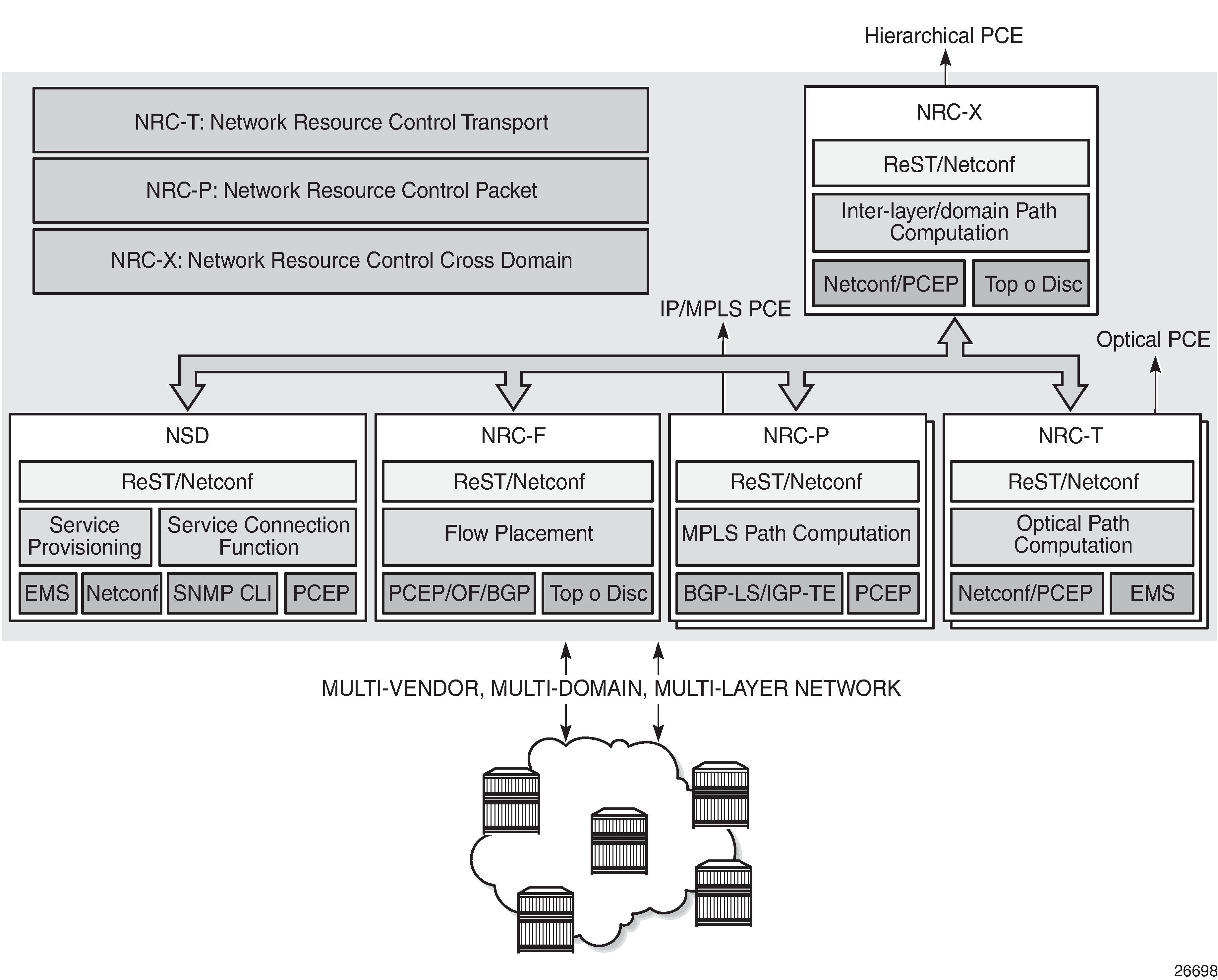
The two main components of the NSP are:
Network Services Director (NSD)
The NSD is a programmable and multi-vendor service provisioning tool providing a single and simple API to the user and OSS. It implements a service model abstraction and adapts to each vendor-specific service model. It supports provisioning services such as E-Line, E-LAN, E-Tree, Layer 3 VPN, traffic steering, and service chaining.
Network Resource Controller (NRC)
The NRC implements separate modules for computing and managing optimal paths for optical tunnels (NRC-T) and MPLS tunnels (NRC-P), and for computing optimal routing and placement of IP flows (NRC-F). In addition, a resource controller for inter-layer IP and optical path computation and more complex inter-domain MPLS path computation is provided as part of the NRC-X.
The Network Resource Controller - Packet (NRC-P) implements the stateful Path Computation Element (PCE) for packet networks. NRC-P Architecture illustrates the NRC-P architecture and its main components.
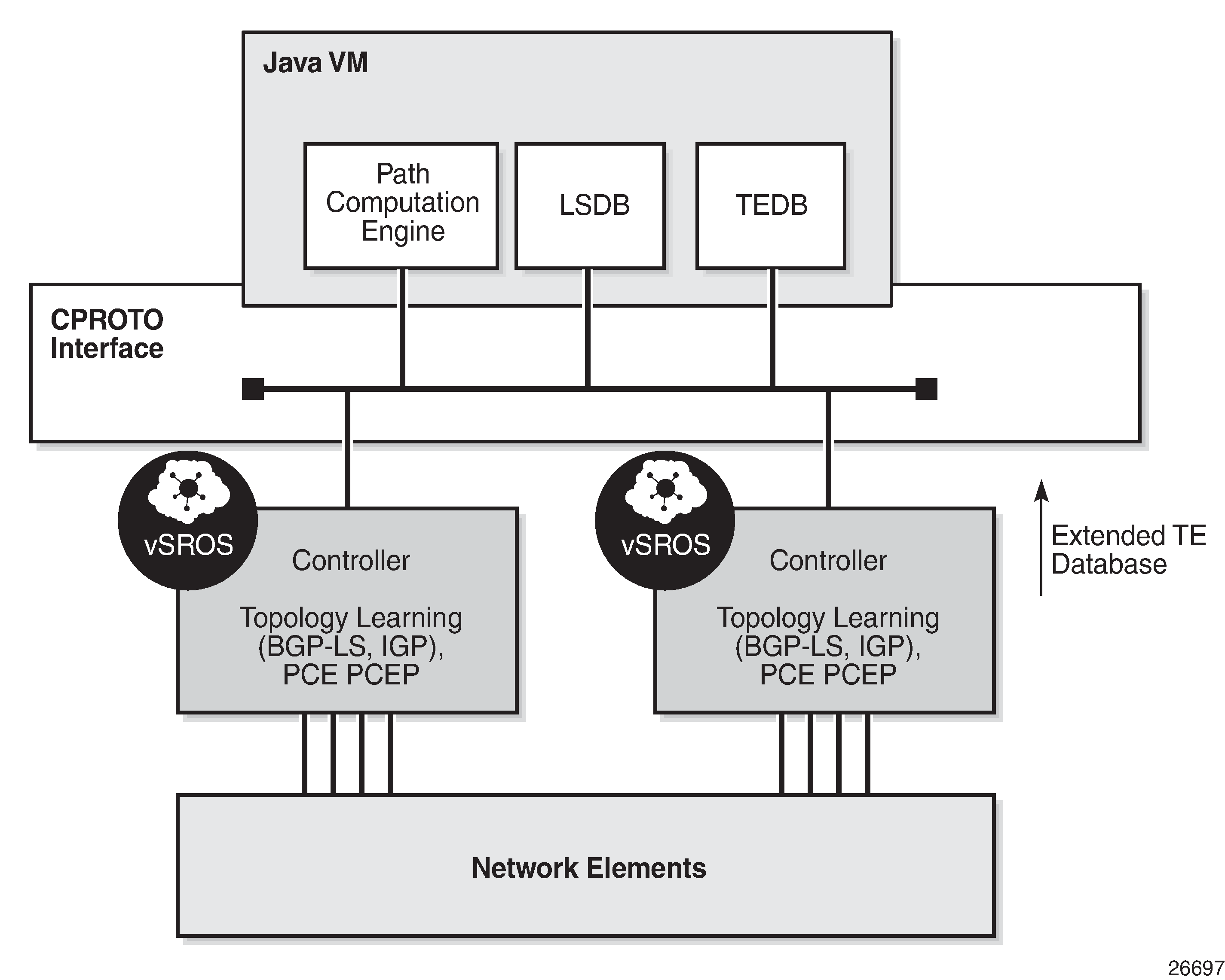
The NRC-P has the following architecture:
a single Virtual Machine (VM) handling the Java implementation of an MPLS path computation engine, a TE graph database, and an LSP database
a plug-in adapter with the Nokia CPROTO interface, providing reliable, TCP-based message delivery between vSROS and Java-VM. The plug-in adapter implements a compact encoding/decoding (codec) function for the message content using Google ProtoBuf. Google ProtoBuf also provides for automatic C++ (vSROS side) and Java (Java-VM side) code generation to process the exchanged message content.
a single VM running a vSROS image that handles the functions of topology discovery of multiple IGP instances and areas via IGP and NSP NFM-P. For larger network domains, one VM running the vSROS image can be dedicated to a specific function.
The PCE module uses PCEP to communicate with its PCE Clients (PCCs). It also uses PCEP to communicate with other PCEs to coordinate inter-domain path computation. Each router acting as a PCC initiates a PCEP session to the PCE in its domain.
When the user enables PCE control for one or more segment routing (SR) or RSVP-TE LSPs, the PCE owns the path updating and periodic reoptimization of the LSPs. In this case, the PCE acts in an active stateful role. The PCE can also act in a passive stateful role for other LSPs on the router by discovering the LSPs and taking into account their resource consumption when computing the path for the LSPs it has control ownership of.
The following is a high-level description of the PCE and PCC capabilities:
base PCEP implementation, as per RFC 5440
active and passive stateful PCE LSP update, as per draft-ietf-pce-stateful-pce
delegation of LSP control to the PCE
synchronization of the LSP database with network elements for PCE-controlled LSPs and network element-controlled LSPs
support for PCC-initiated LSPs, as per draft-ietf-pce-stateful-pce
support for LSP path diversity across different LERs using extensions to the PCE path profile, as per draft-alvarez-pce-path-profiles
support for LSP path bidirectionality constraints using extensions to the PCE path profile, as per draft-alvarez-pce-path-profiles
Path Computation Fallback for PCC-initiated LSPs
For PCC-initiated SR-TE LSPs, the router supports fallback to a local path computation method when the configured PCEP sessions are down or the PCE is unreachable. Fallback to a local computation method can be used when all configured PCEs are signaling overload and the redelegation timer has expired so that the LSP cannot be redelegated.
This capability is supported by both active stateful and passive stateful LSPs. Active stateful LSPs are fully delegated to the PCE by being both PCE-computed (path-computation-method pce) and PCE-controlled. Passive stateful LSPs are PCE-computed.
A fallback path computation method is configured as follows:
configure>router>
   mpls
      lsp <xyz>
         fallback-path-computation-method [none]
         path-computation-method pce
         pce-control
If the fallback path computation method is configured as none, MPLS uses the default method based on the configured path, which is hop-to-label path computation for SR-TE LSPs.
The fallback-path-computation-method command is only valid if path-computation-method pce is enabled.
The fallback mechanism is only triggered if the PCC informs MPLS that PCEP is down. It is not triggered while the PCC is administratively down or if it is not yet configured.
PCE reports are sent, where applicable, with the delegation bit cleared.
Base Implementation of Path Computation Elements (PCE)
The base implementation of the PCE uses the PCEP extensions defined in RFC 5440.
The main functions of PCEP are:
PCEP session establishment, maintenance, and closing
path computation requests using the PCReq message
path computation replies using the PCRep message
notification messages (PCNtf) by which the PCEP speaker can inform its peer about events, such as path request cancellation by the PCC or path computation cancellation by the PCE
error messages (PCErr) by which the PCEP speaker can inform its peer about errors related to processing requests, message objects, or TLVs
Base PCEP TLVs, Objects, and Messages lists the base PCEP TLVs, objects, and messages.
TLV, Object, or Message |
Contained in Object |
Contained in Message |
|---|---|---|
OPEN Object |
N/A |
OPEN, PCErr |
Request Parameter (RP) Object |
N/A |
PCReq, PCRep, PCErr, PCNtf |
NO-PATH Object |
N/A |
PCRep |
END-POINTS Object |
N/A |
PCReq |
BANDWIDTH Object |
N/A |
PCReq, PCRep, PCRpt1 |
METRIC Object |
N/A |
PCReq, PCRep, PCRpt1 |
Explicit Route Object (ERO) |
N/A |
PCRep |
Reported Route Object (RRO) |
N/A |
PCReq |
LSPA Object |
N/A |
PCReq, PCRep, PCRpt1 |
Include Route Object (IRO) |
N/A |
PCReq, PCRep |
SVEC Object |
N/A |
PCReq |
NOTIFICATION Object |
N/A |
PCNtf |
PCEP-ERROR Object |
N/A |
PCErr |
LOAD-BALANCING Object |
N/A |
PCReq |
CLOSE Object |
N/A |
CLOSE |
- Nokia proprietary
The behavior and limitations of the implementation of the objects in Base PCEP TLVs, Objects, and Messages are as follows.
The PCE treats all supported objects received in a PCReq message as mandatory, regardless of whether the P-flag in the object’s common header is set (mandatory object) or not (optional object).
The PCC implementation will always set the B-flag (B=1) in the metric object containing the hop metric value, which means that a bound value must be included in PCReq message. The PCE returns the computed value in the PCRep message with flags set identically to the PCReq message.
The PCC implementation will always set flags B=0 and C=1 in the metric object for the IGP or TE metric values in the PCReq message. This means that the request is to optimize (minimize) the metric without providing a bound value. The PCE returns the computed value in the PCRep message with flags set identically to the PCReq message.
The IRO and LOAD-BALANCING objects are not part of the NSP PCE feature. If the PCE receives a PCReq message with one or more of these objects, it will ignore them regardless of the setting of the P-flag, and will process the path computations normally.
The LSPA, metric, and bandwidth objects are also included in the PCRpt message. The inclusion of these objects in the PCRpt message is proprietary to Nokia.
The following features are not supported on the 7705 SAR:
PCE discovery using IS-IS, per RFC 5089, and OSPF, per RFC 5088, along with corresponding extensions for discovering stateful PCE, per draft-sivabalan-pce-disco-stateful
security of the PCEP session using MD5 or TLS between PCEP peers
PCEP synchronization optimization as per draft-ietf-pce-stateful-sync-optimizations
support of end-to-end secondary backup paths for an LSP. PCE standards do not currently support an LSP container with multiple paths, and the PCE treats each request as a path with a unique PLSP-ID. It is up to the router to tie the two paths together to create 1:1 protection and to request path or SRLG diversity among them when it makes the request to the PCE.
jitter, latency, and packet loss metrics support as per RFC 7471 and draft-ietf-isis-te-metric-extensions, and their use in the PCE metric object as per draft-ietf-pce-pcep-service-aware
PCEP Session Establishment and Maintenance
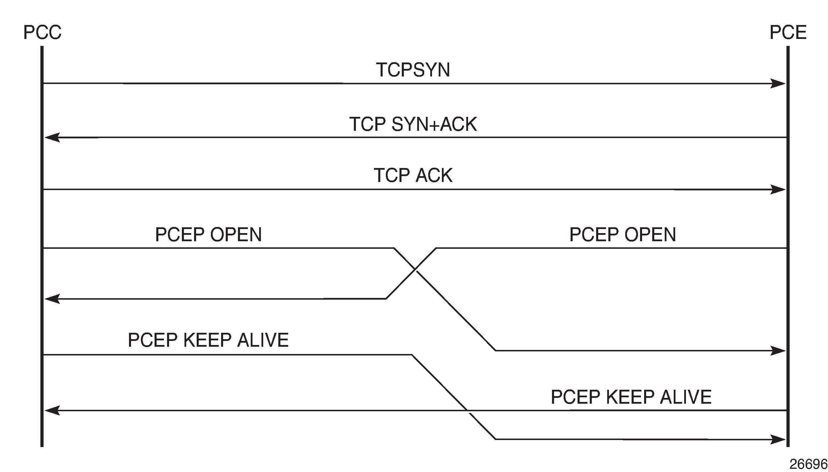
PCEP operates over TCP using destination TCP port 4189. The PCC always initiates the connection. When the user configures the PCEP local address and the peer address on the PCC, the PCC initiates a TCP connection to the PCE. When a connection is established, the PCC and PCE exchange OPEN messages, which initializes the PCEP session and exchanges the session parameters to be negotiated.
By default, the PCC checks first to determine if the remote PCE address is reachable out-of-band via the management port. If the remote address is not reachable, the PCC will try to reach the remote PCE address in-band. To restrict the PCC to only out-of-band or only in-band connection attempts, the route-preference command can be used. When the session comes up out-of-band, the system IP address is always used as the local address; the local address configured by the user is ignored and is only used for an in-band session.
A keepalive mechanism is used as an acknowledgment of the acceptance of the session within the negotiated parameters. It is also used as a maintenance function to detect whether or not the PCEP peer is still alive.
The negotiated parameters include the keepalive timer and the dead timer, and one or more PCEP capabilities such as support of stateful PCE and the LSP Path type.
The PCEP session initialization steps are illustrated in PCEP Session Initialization.
If the session to the PCE times out, the router acting as a PCC keeps the last successfully programmed path provided by the PCE until the session to the PCE is re-established. Any subsequent change to the state of an LSP is synchronized at the time the session is re-established.
When a PCEP session to a peer times out or closes, the rate at which the PCEP speaker attempts the establishment of the session is subject to an exponential back-off mechanism.
PCEP Parameters
The following PCEP parameters are user-configurable on the PCC:
keepalive timer
A PCEP speaker must send a keepalive message if no other PCEP message is sent to the peer at the expiry of this timer. This timer is restarted every time a PCEP message is sent or the keepalive message is sent.
The keepalive mechanism is asymmetric, meaning that each peer can use a different keepalive timer value.
The range of this timer is 1 to 255 seconds and the default value is 30 seconds.
dead timer
This timer tracks the amount of time a PCEP speaker waits after the receipt of the last PCEP message before declaring its peer down.
The dead timer mechanism is asymmetric, meaning that each PCEP speaker can propose a different dead timer value to its peer to use to detect session timeouts.
The range of this timer is 1 to 255 seconds and the default value is 120 seconds.
maximum rate of unknown messages
When the rate of received unrecognized or unknown messages reaches the configured limit, the PCEP speaker closes the session to the peer.
The range of this message rate is 1 to 255 messages per minute and the default value is 10 messages per minute.
session reestablishment and state timeout
If the PCEP session to the PCE goes down, all delegated PCC-initiated LSPs have their state maintained in the PCC and are not timed out. The PCC continues to try re-establishing the PCEP session. When the PCEP session is re-established, the LSP database is synchronized with the PCE database, and any LSP that went down since the last time the PCEP session was up has its path updated by the PCE.
PCC Configuration
The following PCC parameters can be modified while the PCEP session is operational:
report-path-constraints
unknown-message-rate
The following PCC parameters cannot be modified while the PCEP session is operational:
local-address
keepalive
dead-timer
peer (regardless of shutdown state)
Stateful PCE
The main function introduced by stateful PCE over the base PCE implementation is the ability to synchronize the LSP state between the PCC and the PCE. This allows the PCE to have all the required LSP information to perform reoptimization and updating of the LSP paths.
PCEP Stateful PCE Extension TLVs, Objects, and Messages describes the TLVs, objects, and messages supported by stateful PCE on the 7705 SAR.
TLV, Object, or Message |
Contained in Object |
Contained in Message |
|---|---|---|
Path Computation State Report (PCRpt) |
N/A |
New message |
Path Computation Update Request (PCUpd) |
N/A |
New message |
STATEFUL-PCE-CAPABILITY TLV |
OPEN |
OPEN |
Stateful Request Parameter (SRP) Object |
N/A |
PCRpt1, PCErr |
LSP Object |
ERO |
PCRpt1, PCReq, PCRep |
LSP-IDENTIFIERS TLV |
LSP |
PCRpt1 |
SYMBOLIC-PATH-NAME TLV |
LSP, SRP |
PCRpt1 |
LSP-ERROR-CODE TLV |
LSP |
PCRpt1 |
RSVP-ERROR-SPEC TLV |
LSP |
PCRpt1 |
- Nokia proprietary
The behavior and limitations of the implementation of the TLVs, objects, and messages in PCEP Stateful PCE Extension TLVs, Objects, and Messages are as follows.
The PCC and PCE support all PCEP capability TLVs defined in this document and will always advertise them. If the OPEN object received from a PCEP speaker does not contain one or more of the capabilities, the PCE or PCC will not use them during that specific PCEP session.
The PCC always includes the LSP object in the PCReq message to make sure that the PCE can correlate the PLSP-ID for this LSP when a subsequent PCRpt message arrives with the delegation bit set. The PCE will, however, still honor a PCReq message without the LSP Object.
PCE path computation will only consider the bandwidth used by LSPs in its LSP-DB. As a result, there are two situations where PCE path computation will not accurately take into account the bandwidth used in the network:
when there are LSPs that are signaled by the routers but are not synchronized with the PCE. The user can enable the reporting of the LSP to the PCE LSP database for each LSP.
when the stateful PCE is peering with a third-party stateless PCC, implementing only the original RFC 5440. While the PCE will be able to bring the PCEP session up, the LSP database will not be updated, because stateless PCC does not support the PCRpt message. Therefore, PCE path computation will not accurately take into account the bandwidth used by these LSPs in the network.
The PCE ignores the R-flag (reoptimize flag) in the PCReq message when acting in passive stateful mode for an LSP and will always return the newly computed path, regardless whether it is link-by-link identical or has the same metric as the current path. The decision whether to initiate the new path in the network belongs to the PCC.
The synchronization vector (SVEC) object is not supported on the 7705 SAR and the NSP. If the PCE receives a PCReq message with the SVEC object, it will ignore the SVEC object and treat each path computation request in the PCReq message as independent, regardless of the setting of the P-flag in the SVEC object common header.
When an LSP is delegated to the PCE, there may be no prior state in the NRC-P LSP database for the LSP. This could be due to the PCE not having received a PCReq message for the same PLSP-ID. In order for the PCE to become aware of the original constraints of such an LSP, the following additional procedures are performed. These procedures are proprietary to Nokia.
The PCC appends a duplicate of each of the LSPA, metric, and bandwidth objects in the PCRpt message. The only difference between the two objects of the same type is that the P-flag is set in the common header of the duplicate object to indicate a mandatory object for processing by the PCE.
The value of the metric or bandwidth in the duplicate object contains the original constraint value, while the first object contains the operational value. This is applicable to hop metrics in the metric object and bandwidth object only. The 7705 SAR PCC does not support putting a bound value on the IGP or TE metric in the path computation.
The path computation on the PCE uses the first set of objects when updating a path if the PCRpt message contains a single set. If the PCRpt message contains a duplicate set, PCE path computation must use the constraints in the duplicate set.
For interoperability, implementations compliant with PCEP standards should be able to accept the first metric object and ignore the second object without additional error handling. Because there are also bandwidth and LSPA objects, the [no] report-path-constraints command is provided in the PCC on a per-PCEP session basis to disable the inclusion of the duplicate objects. Duplicate objects are included by default.
PCEP Extensions in Support of SR-TE LSPs
In order for the PCE and PCC to manage the path of an SR-TE LSP, they both implement the following extensions to PCEP in support of segment routing.
The PCC and PCE support a Segment Routing capability TLV in the OPEN object to indicate support of segment routing tunnels by the PCE and the PCC during PCEP session initialization. This TLV is referred to as the SR-PCE-CAPABILITY TLV.
The PCC and PCE support all PCEP capability TLVs defined in this chapter and will always advertise them. If the OPEN object received from a PCEP speaker does not contain one or more of the capabilities, the PCE or the PCC will not use them during that specific PCEP session.
The PCC and PCE support a new Path Setup Type TLV for SR-TE LSPs to be included in the Stateful PCE Request Parameters (SRP) object during path report (PCRpt) messages by the PCC.
A Path Setup Type TLV with a value of 1 identifies an SR-TE LSP.
The PCC and PCE support a new Segment Routing ERO and RRO with sub-objects, referred to as SR-ERO and SR-RRO sub-objects, which encode the SID information in PCRpt messages.
The PCE implementation supports the Segment-ID (SID) Depth value in the METRIC object. This is always signaled by the PCC in the PCEP Open object as part of the SR-PCE-CAPABILITY TLV. It is referred to as the Maximum Stack Depth (MSD). In addition, the per-LSP value for the max-sr-labels option, if configured, is signaled by the PCC to the PCE in the SID Depth value in a METRIC object for both a PCE-computed LSP and a PCE-controlled LSP. The PCE will compute and provide the full explicit path with TE links specified. If there is no path with the number of hops lower than the MSD value or the SID Depth value (if signaled), a reply with no path will be returned to the PCC. For a PCC-controlled LSP, if the label stack returned by the TE-DB hop-to-label translation exceeds the per-LSP maximum SR label stack size, the LSP is brought down.
If the Path Setup Type (PST) TLV is not included in the PCReq message, the PCE or PCC must assume it is for an RSVP-TE LSP.
PCEP Segment Routing Extension Objects and TLVs describes the segment routing extension objects and TLVs supported on the 7705 SAR.
TLV, Object, or Message |
Contained in Object |
Contained in Message |
|---|---|---|
SR PCE CAPABILITY TLV |
OPEN |
OPEN |
Path Setup Type (PST) TLV |
SRP |
PCReq, PCRep, PCRpt1 |
SR-ERO sub-object |
ERO |
PCRep, PCRpt1 |
SR-RRO sub-object |
RRO |
PCReq, PCRpt1 |
Segment-ID (SID) Depth Value in METRIC object |
METRIC |
PCReq, PCRpt1 |
- Nokia proprietary
LSP Initiation
An LSP that is configured on the router is referred to as a PCC-initiated LSP. An LSP that is not configured on the router, but is instead created by the PCE at the request of an application or a service instantiation, is referred to as a PCE-initiated LSP.
The 7705 SAR supports three modes of operation for PCC-initiated LSPs, which are configurable on a per-LSP basis:
PCC-initiated and PCC-controlled
When the path of the LSP is computed and updated by the router acting as a PCE Client (PCC), the LSP is referred to as PCC-initiated and PCC-controlled.
A PCC-initiated and PCC-controlled LSP has the following characteristics:
The LSP can contain strict or loose hops, or a combination of both.
CSPF is supported for RSVP-TE LSPs. Local path computation takes the form of hop-to-label translation for LSPs.
LSPs can be reported to synchronize the LSP database of a stateful PCE server using the pce-report option. In this case, the PCE acts in passive stateful mode for this LSP. The LSP path cannot be updated by the PCE. The control of the LSP is maintained by the PCC.
PCC-initiated and PCE-computed
When the path of the LSP is computed by the PCE at the request of the PCC, it is referred to as PCC-initiated and PCE-computed.
A PCC-initiated and PCE-computed LSP has the following characteristics:
The path-computation-method pce option must be enabled for the LSP so that the PCE can perform path computation at the request of the PCC only. The PCC retains control.
LSPs can be reported to synchronize the LSP database of a stateful PCE server using the pce-report option. In this case, the PCE acts in passive stateful mode for this LSP.
PCC-initiated and PCE-controlled
When the path of the LSP is updated by the PCE following a delegation from the PCC, it is referred to as PCC-initiated and PCE-controlled.
A PCC-initiated and PCE-controlled LSP has the following characteristics:
The pce-control option must be enabled for the LSP so that the PCE can perform path updates following a network event without an explicit request from the PCC. The PCC delegates full control.
The pce-report option must be enabled for LSPs that cannot be delegated to the PCE. The PCE acts in active stateful mode for this LSP.
PCC-Initiated and PCE-Computed or PCE-Controlled LSPs
The following is the procedure for configuring and programming a PCC-initiated LSP when control is delegated to the PCE.
The LSP configuration is created on the PE router via CLI or via the OSS/NSP NFM-P.
The configuration dictates which PCE control mode is desired: active (pce-control and pce-report options enabled) or passive (path-computation-method pce enabled and pce-control disabled).
PCC assigns a unique PLSP-ID to the LSP. The PLSP-ID uniquely identifies the LSP on a PCEP session and must remain constant during its lifetime. PCC on the router must keep track of the association of the PLSP-ID to the Tunnel-ID and Path-ID, and use the latter to communicate with MPLS about a specific path of the LSP. PCC also uses the SRP-ID to correlate PCRpt messages for each new path of the LSP.
The PE router does not validate the entered path. Note however that in the 7705 SAR, the PCE supports the computation of a path for an LSP with empty-hops in its path definition. While PCC will include the IRO objects in the PCReq message to PCE, the PCE will ignore them and compute the path with the other constraints except the IRO.
The PE router sends a PCReq message to the PCE to request a path for the LSP, and includes the LSP parameters in the METRIC object, the LSPA object, and the BANDWIDTH object. The PE router also includes the LSP object with the assigned PLSP-ID. At this point, the PCC does not delegate the control of the LSP to the PCE.
The PCE computes a new path, reserves the bandwidth, and returns the path in a PCRep message with the computed ERO in the ERO object. It also includes the LSP object with the unique PLSP-ID, the METRIC object with any computed metric value, and the BANDWIDTH object.
Note: For the PCE to be able to use the SRLG path diversity and admin-group constraints in the path computation, the user must configure the SRLG and admin-group membership against the MPLS interface and make sure that the traffic-engineering option is enabled in IGP. This causes IGP to flood the link SRLG and admin-group membership in its participating area, and for PCE to learn it in its TE database.The PE router updates the CPM and the data path with the new path.
Up to this point, the PCC and PCE are using passive stateful PCE procedures. The next steps will synchronize the LSP database of the PCC and PCE for both PCE-computed and PCE-controlled LSPs. They will also initiate the active PCE stateful procedures for the PCE-controlled LSP only.
The PE router sends a PCRpt message to update the PCE with an Up state, and also sends the RRO as confirmation. It now includes the LSP object with the unique PLSP-ID. For a PCE-controlled LSP, the PE router also sets the delegation control flag to delegate control to the PCE. The state of the LSP is now synchronized between the router and the PCE.
Following a network event or a reoptimization, the PCE computes a new path for a PCE-controlled LSP and returns it in a PCUpd message with the new ERO. It will include the LSP object with the same unique PLSP-ID assigned by the PCC, as well as the Stateful Request Parameter (SRP) object with a unique SRP-ID to track error and state messages specific to this new path.
The PE router updates the CPM and the data path with the new path.
The PE router sends a PCRpt message to inform the PCE that the older path is deleted. It includes the unique PLSP-ID value in the LSP object and the R (Remove) bit set.
The PE router sends a new PCRpt message to update PCE with an Up state, and also sends the RRO to confirm the new path. The state of the LSP is now synchronized between the router and the PCE.
If PCE owns the delegation of the LSP and is making a path update, MPLS will initiate the LSP and update the operational value of the changed parameters while the configured administrative values will not change. Both the administrative and operational values are shown in the details of the LSP path in MPLS.
If the user makes any configuration change to the PCE-computed or PCE-controlled LSP, MPLS requests that the PCC first revoke delegation in a PCRpt message (PCE-controlled only), and then MPLS and PCC follow the above steps to convey the changed constraint to PCE which will result in the programming of a new path into the data path, the synchronization of the PCC and PCE LSP databases, and the return of delegation to PCE.
The above procedure is followed when the user performs a no shutdown command on a PCE-controlled or PCE-computed LSP. The starting point is an LSP which is administratively down with no active path. For an LSP with an active path, the following items may apply:
If the user enabled the path-computation-method pce option on a PCC-controlled LSP with an active path, no action is performed until the next time the router needs a path for the LSP following a network event of a LSP parameter change. At that point, the prior procedure is followed.
If the user enabled the pce-control option on a PCC-controlled or PCE-computed LSP with an active path, the PCC will issue a PCRpt message to the PCE with an Up state, as well as the RRO of the active path. It will set the delegation control flag to delegate control to the PCE. The PCE will keep the active path of the LSP and make no updates to it until the next network event or reoptimization. At that point, the prior procedure is followed.
PCEP over TLS
PCEP over TLS (PCEPS) uses Transport Layer Security (TLS) to provide secure communication for PCEP. The secured session uses port 4189. The PCC is configured with a TLS client profile to initiate the TLS handshake. The PCE is configured with a TLS server profile to allow PCEP over TLS.
When a TLS server profile is configured on the PCE, the PCE can establish TLS connections in PCE secured (PCES) mode or non-TLS connections in PCE mode.
On the PCC, the 7705 SAR supports only strict TLS. That is, when the PCC is configured with a TLS client profile, the PCE must be TLS-capable and in PCES mode in order to establish a TLS connection. The PCE and PCC must perform a successful TLS handshake before the TLS wait timer expires.
If the PCC is not configured with a TLS client profile, the PCC and PCE can still make a connection in PCE mode, even if the PCE is configured with a TLS server profile.
In PCES mode, both the PCC and PCE must provide certificates for authentication. The PCE provides the server certificate to the PCC and requires the client certificate to authenticate the PCC.
TLS handshake
The 7705 SAR supports TLS client (PCC) functionality as well as TLS bidirectional authentication, where the PCE requests the client certificate to authenticate the PCC.
In a typical TLS handshake, the client starts the handshake with a ClientHello message. The server provides the server certificate for authentication to the client and sends a list of server-accepted ciphers.
The server can optionally ask the client to provide the client certificate using the server CertificateRequest option. When this option is present, the client provides the server with the client certificate, and if the certificate is authenticated, the TLS symmetric key is negotiated and the TLS session is established. The symmetric key is used to encrypt the TLS datapath.
See the 7705 SAR System Management Guide for more information about the TLS handshake steps.
PCEP session over TLS
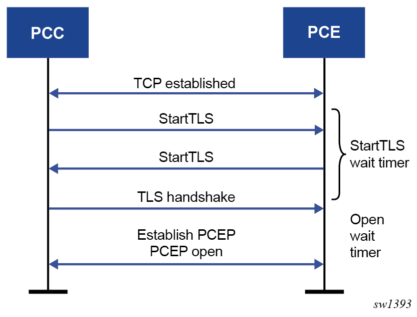
To establish a PCEP session over TLS as specified in RFC 8253, the PCC sends a StartTLS message to the PCE to initiate the TLS negotiation. The PCC activates the StartTLS timer and waits for the StartTLS message from the PCE. The timer is configured using the config>router>pcep>pcc>peer>tls-wait-timer command; the default timer is 60 s.
If the PCE is TLS-capable and sends back a StartTLS message before the StartTLS timer expires, the TLS handshake is initiated. If the PCE sends an Open message or does not send back a StartTLS message, the PCC responds with an error message, closes the TCP connection, and tries to establish the connection again. The PCEP Message-Type field of the PCEP common header for the StartTLS message is set to 13, as specified in RFC 8253. The following figure shows the establishment of a PCEP session over TLS.
TLS supports both in-band and out-of-band PCE connections.
PCEP Support for RSVP-TE LSPs
This section describes the support of PCC-initiated RSVP-TE LSPs. PCEP support of an RSVP-TE LSP is described in LSP Initiation with the following differences:
each primary and secondary path is assigned its own unique path LSP-ID (PLSP-ID)
the PCC indicates to the PCE the state of each path (either up or down) and which path is currently active and carrying traffic (active state)
This section includes the following topics:
RSVP-TE LSP Configuration for a PCC Router
The following MPLS-level and LSP-level CLI commands are used to configure RSVP-TE LSPs in a router acting as a PCEP Client (PCC). See MPLS and RSVP-TE Command Reference for command descriptions.
config>router>mpls>
pce-report rsvp-te {enable | disable}
config>router>mpls>lsp>
path-profile profile-id [path-group group-id]
path-computation-method pce
pce-control
pce-report {enable | disable | inherit}
config>router>mpls>lsp-template
pce-report {enable | disable | inherit}
The cspf option must be enabled on the LSP before enabling the path-computation-method pce or pce-control options. An attempt to disable the cspf option on an RSVP-TE LSP that has the path-computation-method pce or pce-control options enabled will be rejected.
If the LSP has disabled PCE reporting, either due to inheritance from the MPLS-level configuration or due to LSP-level configuration, enabling the pce-control option for the LSP has no effect. To help troubleshoot this situation, the output of the show commands for the LSP displays the operational values of both the pce-report and pce-control options.
A one-hop-p2p or a mesh-p2p RSVP-TE auto-lsp only supports the pce-report command in the LSP template:
config>router>mpls>lsp-template>pce-report {enable | disable | inherit}
The user must first shut down the LSP template before changing the value of the pce-report option.
A manual bypass LSP does not support any of the PCE-related commands. Reporting a bypass LSP to the PCE is not required because the bypass LSP does not book bandwidth.
All other MPLS, LSP, and path-level commands are supported, with the exception of the following commands:
least-fill
srlg (on secondary standby path)
For more information about RSVP-TE PCC instantiation modes, see LSP Initiation.
Behavior of the LSP Path Update
When the pce-control option is enabled, the PCC delegates control of the RSVP-TE LSP to the PCE.
The NRC-P sends a path update using the PCUpd message in the following cases:
-
a failure event that impacts a link or a node in the path of a PCE-controlled LSP
The operation is performed by the PCC as a Make-Before-Break (MBB) if the LSP remained in the up state due to protection provided by FRR or a secondary path. If the LSP went down, the update brings it into the up state. A PCRpt message is sent by the PCC for each change to the state of the LSP during this process. See Behavior of LSP MBB for more information.
-
a topology change that impacts a link in the path of a PCE-controlled LSP
This topology change can be a change to the IGP metric, the TE metric, admin-group, or SRLG membership of an interface. This update is performed as an MBB by the PCC.
-
the user performed a manual resignal of a PCE-controlled RSVP-TE LSP path from the NRC-P
This update is performed as an MBB by the PCC.
-
the user performed a Global Concurrent Optimization (GCO) on a set of PCE-controlled RSVP-TE LSPs from the NRC-P
This update is performed as an MBB by the PCC.
The procedures for the path update are described in LSP Initiation. However, for an RSVP-TE LSP, the PCUpd message from the PCE contains the interface IP address or system IP address in the computed ERO. The PCC signals the path using the ERO returned by the PCE and, if successful, programs the data path, then sends the PCRpt message with the resulting RRO and hop labels provided by RSVP-TE signaling.
If the signaling of the ERO fails, the ingress LER returns a PCErr message to the PCE with the LSP Error code field of the LSP-ERROR-CODE TLV set to a value of 8 (RSVP signaling error).
If an RSVP-TE LSP has the no adaptive option set, the ingress LER cannot perform an MBB for the LSP. A PCUpd message received from the PCE is then failed by the ingress LER, which returns a PCErr message to the PCE with the LSP Error code field of the LSP-ERROR-CODE TLV set to a value of 8 (RSVP signaling error).
Path Update with Empty ERO
When the NRC-P reoptimizes the path of a PCE-controlled RSVP-TE LSP, it is possible that a path that satisfies the constraints of the LSP no longer exists. In this case, the NRC-P sends a PCUpd message with an empty ERO, which forces the PCC to bring down the path of the RSVP-TE LSP.
The NRC-P sends a PCUpd message with an empty ERO if any of the following cases are true:
the requested bandwidth is the same as the current bandwidth, which avoids bringing down the path due to a resignal during an MBB transition
local protection is not currently in use, which avoids bringing down a path that activated an FRR backup path. The LSP can remain on the FRR backup path until a new primary path can be found by the NRC-P.
the links of the current path are all operationally up, which allows the NRC-P to ensure that the RSVP control plane will report the path down when a link is down and not prematurely bring the path down with an empty ERO
Behavior of LSP MBB
In addition to the MBB support when the PCC receives a path update, as described in Behavior of the LSP Path Update, an RSVP-TE LSP supports the MBB procedure for any parameter configuration change, including the PCEP-related commands when they result in a change to the path of the LSP.
If the user adds or modifies the path-profile command for an RSVP-TE LSP, a config change MBB is only performed if the path-computation-method pce, pce-report, or pce-control options are enabled on the LSP. Otherwise, no action occurs. When path-computation-method pce, pce-report, or pce-control are enabled on the LSP, the path update MBB (tools>perform>router>mpls>update-path) fails, resulting in no operation.
MBB is also supported for the manual resignal and auto-bandwidth MBB types.
When the LSP goes into an MBB state at the ingress LER, the behavior is dependent on the operating mode of the LSP.
This section contains information about the following LSP MBB procedures:
PCC-Controlled LSPs
All MBB types are supported for PCC-controlled LSPs. The LSP MBB procedures for a PCC-controlled LSP (path-computation-method pce and pce-control disabled) are as follows.
MPLS submits a path request, including the updated path constraints, to the local CSPF.
If the local CSPF returns a path, the PCC signals the LSP with the RSVP control plane and moves traffic to the new MBB path. If pce-report is enabled for this LSP, the PCC sends a PCRpt message with the delegation bit clear to retain control and containing the RRO and LSP objects, with the LSP-IDENTIFIERS TLV containing the LSP-ID of the new MBB path. The message includes the metric, LSPA, and bandwidth objects where the P-flag is clear, which indicates the operational values of these parameters. Unless the user disables the report-path-constraints option under the pcc context, the PCC also includes a second set of metric, LSPA, and bandwidth objects with the P-flag set to convey to the PCE the constraints of the path.
If the CSPF returns no path or the RSVP-TE signaling of the returned path fails, MPLS puts the LSP into retry mode and sends a request to the local CSPF every retry-timer seconds and up to the value of retry-count.
When pce-report is enabled for the LSP and the FRR global revertive MBB is triggered following a bypass LSP activation by a PLR in the network, the PCC issues an updated PCRpt message with the new RRO reflecting the PLR and RRO hops. The PCE releases the bandwidth on the links that are no longer used by the LSP path.
PCE-Computed LSPs
All MBB types are supported for PCE-computed LSPs. The LSP MBB procedures for a PCE-computed LSP (path-computation-method pce enabled and pce-control disabled) are as follows.
The PCC issues a PCReq for the same PLSP-ID and includes the updated constraints in the metric, LSPA, and bandwidth objects.
If the PCE successfully finds a path, it replies with a PCRep message with the ERO.
If the PCE does not find a path, it replies with a PCRep message containing the No-Path object.
If the PCE returns a path, the PCC signals the LSP with the RSVP control plane and moves traffic to the new MBB path. If pce-report is enabled for this LSP, the PCC sends a PCRpt message with the delegation D-bit clear to retain control and containing the RRO and LSP objects, with the LSP-IDENTIFIERS TLV containing the LSP-ID of the new MBB path. The message includes the metric, LSPA, and bandwidth objects where the P-flag is clear, which indicates the operational values of these parameters. Unless the user disables the report-path-constraints option under the pcc context, the PCC also includes a second set of metric, LSPA, and bandwidth objects with the P-flag set to convey to the PCE the constraints of the path.
If the PCE returns no path or the RSVP-TE signaling of the returned path fails, MPLS puts the LSP into retry mode and sends a request to PCE every retry-timer seconds and up to the value of retry-count.
When the pce-report is enabled for the LSP and the FRR global revertive MBB is triggered following a bypass LSP activation by a PLR in the network, the PCC issues an updated PCRpt message with the new RRO reflecting the PLR and RRO hops. The PCE releases the bandwidth on the links that are no longer used by the LSP path.
If the user changes the RSVP-TE LSP configuration from path-computation-method pce to no path-computation-method, MBB procedures are not supported. In this case, the LSP path is torn down and is put into retry mode to compute a new path from the local CSPF on the router to signal the LSP.
PCE-Controlled LSPs
The LSP MBB procedures for a PCE-controlled LSP (pce-control enabled) are as follows.
The PCC temporarily removes delegation by sending a PCRpt message for the corresponding path LSP-ID (PLSP-ID) with the delegation D-bit clear.
For an LSP with path-computation-method pce disabled, MPLS submits a path request to the local CSPF, which includes the updated path constraints.
For an LSP with path-computation-method pce enabled, the PCC issues a PCReq for the same PLSP-ID and includes the updated constraints in the metric, LSPA, or bandwidth objects.
If the PCE successfully finds a path, it replies with a PCRep message with the ERO.
If the PCE does not find a path, it replies with a PCRep message containing the No-Path object.
If the local CSPF or the PCE returns a path, the PCC performs the following actions.
The PCC signals the LSP with the RSVP control plane and moves traffic to the new MBB path. It then sends a PCRpt message with the delegation D-bit set to return delegation and containing the RRO and LSP objects, with the LSP-IDENTIFIERS TLV containing the LSP-ID of the new MBB path. The message includes the metric, LSPA, and bandwidth objects where the P-flag is clear, which indicates the operational values of these parameters. Unless the user disabled the report-path-constraints option under the pcc context, the PCC also includes a second set of metric, LSPA, or bandwidth objects with the P-flag set to convey to the PCE the constraints of the path.
The PCC sends a PathTear message to delete the state of the older path in the network. The PCC then sends a PCRpt message to the PCE with the older path LSP (PLSP-ID) and the remove R-bit set to also have the PCE remove the state of that LSP from its database.
If the local CSPF or the PCE returns no path or the RSVP-TE signaling of the returned path fails, the router makes no further requests. That is, there is no retry for the MBB.
The PCC sends a PCErr message to the PCE with the LSP Error code field of the LSP-ERROR-CODE TLV set to a value of 8 (RSVP signaling error) if the MBB failed due to a RSVP-TE signaling error.
The PCC sends a PCRpt message with the delegation D-bit set to return delegation and containing the RRO and LSP objects, with the LSP-IDENTIFIERS TLV containing the LSP-ID of the currently active path. The message includes the metric, LSPA, and bandwidth objects where the P-flag is clear to indicate the operational values of these parameters. Unless the user disabled the report-path-constraints option under the pcc context, the PCC also includes a second set of metric, LSPA, and bandwidth objects with the P-flag set to convey to the PCE the constraints of the path.
The ingress LER takes no action in the case of a network event triggered MBB, such as FRR global revertive or TE graceful shutdown.
The ingress PE keeps the information as required and sets the state of MBB to one of the FRR global revertive or TE graceful shutdown MBB values but does not perform the MBB action.
The NRC-P computes a new path for the global revertive MBB due to a failure event. This computation uses the PCUpd message to update the path using the MBB procedure described in Behavior of the LSP Path Update. The activation of a bypass LSP by a point of local repair (PLR) in the network causes the PCC to issue an updated PCRpt message with the new RRO reflecting the PLR and RRO hops. The PCE will release the bandwidth on the links that are no longer used by the LSP path.
The NRC-P computes a new path for the TE graceful shutdown MBB if the RSVP-TE is using the TE metric, because the TE metric of the link in TE graceful shutdown is set to infinity. This computation uses the PCUpd message to update the path using the MBB procedure described in Behavior of the LSP Path Update.
The NRC-P does not act on the TE graceful shutdown MBB if the RSVP-TE is using the IGP metric; however, the user can perform a manual resignal of the LSP path from the NRC-P to force a new path computation, which accounts for the newly available bandwidth on the link that caused the MBB event. This computation uses the PCUpd message to update the path using the MBB procedure described in Behavior of the LSP Path Update.
The user can perform a manual resignal of the LSP path from the ingress LER, which forces an MBB for the path as per the remove-delegation/MBB/return-delegation procedures described in this section.
If the user performs no pce-control while the LSP still has the state for any of the network event triggered MBBs, MBB is performed immediately by the PCC as described in the procedures in PCE-Computed LSPs for a PCE-computed LSP and as described in the procedures in PCC-Controlled LSPs for a PCC-controlled LSP.
The timer-based manual resignal MBB functions as the TE graceful shutdown MBB. The user can perform a manual resignal of the LSP path from the ingress LER or from the PCE.
The path update MBB (tools>perform>router>mpls>update-path) fails, which results in no operation. This is true in all cases when the RSVP-TE LSP enables the pce-report option.
Behavior of Secondary LSP Paths
Each of the primary, secondary standby, and secondary non-standby paths of the same LSP must use a separate path LSP-ID (PLSP-ID). The PCE function of the NSP, the NRC-P, checks the LSP-IDENTIFIERS TLV in the LSP object and can identify which PLSP-IDs are associated with the same LSP or the same RSVP-TE session. The parameters are the IPv4 Tunnel Sender Address, the Tunnel ID, the Extended Tunnel ID, and the IPv4 Tunnel Endpoint Address. This approach allows the use of all the PCEP procedures for all three types of LSP paths.
The PCC indicates to the PCE the following states for the path in the LSP object: down, up (signaled but not carrying traffic), or active (signaled and carrying traffic).
The PCE tracks active paths and displays them in the NSP GUI. It also provides only the tunnel ID of an active PLSP-ID to a destination prefix when a request is made by a service or a steering application.
The PCE recomputes the paths of all PLSP-IDs that are affected by a network event. The user can select each path separately on the NSP GUI and trigger a manual resignal of one or more paths of the RSVP-TE LSP.
PCE Path Profile Support
The PCE path profile ID and path group ID are configured at the LSP level (config>router>mpls>lsp>path-profile).
The NRC-P can enforce path disjointness and bidirectionality among a pair of forward and a pair of reverse LSP paths. Both pairs of LSP paths must use a unique path group ID along with the same path profile ID.
When the user wants to apply path disjointness and path bidirectionality constraints to RSVP-TE LSP paths, it is important to follow the following guidelines. The user can configure the following sets of LSP paths:
a set consisting of a pair of forward RSVP-TE LSPs and a pair of reverse RSVP-TE LSPs, each with a single primary or secondary path. The pair of forward LSPs can originate and terminate on different routers. The pair of reverse LSPs must mirror the forward pair. In this case, the path profile ID and the path group ID configured for each LSP must match. Because each LSP has a single path, the bidirectionality constraint applies automatically to the forward and reverse LSPs, which share the same originating node and the same terminating routers.
a pair consisting of a forward RSVP-TE LSP and a reverse RSVP-TE LSP, each with a primary path and a single secondary path, or each with two secondary paths. Because the two paths of each LSP inherit the same LSP level path profile ID and path group ID configuration, the NRC-P path computation algorithm cannot guarantee that the primary paths in both directions meet the bidirectionality constraint. That is, it is possible that the primary path for the forward LSP shares the same links as the secondary path of the reverse LSP and vice versa.
LSP Path Diversity and Bidirectionality Constraints with Path Profiles
The PCE path profile defined in draft-alvarez-pce-path-profiles is used to request path diversity or a disjoint for two or more LSPs originating on the same or different PE routers. It is also used to request that paths of two unidirectional LSPs between the same two routers use the same TE links. This is referred to as the bidirectionality constraint. As an alternative, the 7705 SAR supports the use of association groups to signal path diversity constraints. See PCEP Association Groups for information about association group support.
The configuration of an association group for an LSP and the configuration of the path profile ID and path group ID are mutually exclusive. A path profile and an association group are not interoperable. That is, LSPs with a path profile and those with an association group cannot be considered in the same group and cannot be compared against each other.
Path profiles are defined by the user directly on the NRC-P Policy Manager with a number of LSP path constraints, which are metrics with upper bounds specified, and with an objective, which are metrics optimized with no bounds specified. The NRC-P Policy Manager allows the following PCE constraints to be configured within each PCE path profile:
-
path diversity, node-disjoint, link-disjoint
-
path bidirectionality, symmetric reverse route preferred, symmetric reverse route required
-
maximum path IGP metric (cost)
-
maximum path TE metric
-
maximum hop count
The user can also specify which PCE objective to use to optimize the path of the LSP in the PCE path profile, one of:
-
IGP metric (cost)
-
TE metric
-
hops (span)
The CSPF algorithm optimizes the objective. If a constraint is provided for the same metric, the CSPF algorithm ensures that the selected path achieves a lower or equal value to the bound value specified in the constraint.
For hop-count metrics, if a constraint is sent in a metric object and is also specified in a PCE profile referenced by the LSP, the constraint in the metric object is used.
For IGP and TE metrics, if an objective is sent in a metric object and is also specified in a PCE profile referenced by the LSP, the objective in the path profile is used.
The constraints in the bandwidth object and the LSPA object, specifically the include and exclude admin-group constraints and setup and hold priorities, are not supported in the PCE profile.
In order to indicate the path diversity and bidirectionality constraints to the PCE, the user must configure the profile ID and path group ID of the PCE path that the LSP belongs to. The CLI commands for this are described in Configuring RSVP-TE LSPs with PCEP Using the CLI. The path group ID does not need to be defined in the PCE as part of the path profile configuration and identifies implicitly the set of paths that must have the path diversity constraint applied.
The user can only associate a single path group ID with a specific PCE path profile ID for an LSP. However, the same path group ID can be associated with multiple PCE profile IDs for the same LSP.
The path profiles are inferred using the path ID in the path request by the PCC. When the PE router acting as a PCC wants to request path diversity from a set of other LSPs belonging to a path group ID value, it adds a new PATH-PROFILE object in the PCReq message. The object contains the path profile ID and the path group ID as an extended ID field. In other words, the diversity metric is carried in an opaque way from the PCC to the PCE.
The bidirectionality constraint operates the same way as the diversity constraint. The user can configure a PCE profile with both the path diversity and bidirectionality constraints. The PCE will check if there is an LSP in the reverse direction that belongs to the same path group ID as an originating LSP it is computing the path for, and will enforce the constraint.
In order for the PCE to be aware of the path diversity and bidirectionality constraints for an LSP that is delegated but for which there is no prior state in the NRC-P LSP database, the PATH-PROFILE object is included in the PCRpt message with the P-flag set in the common header to indicate that the object must be processed. This is proprietary to Nokia.
The following table describes the new objects and TLVs introduced in the PCE path profile.
|
TLV, Object, or Message |
Contained in Object |
Contained in Message |
|---|---|---|
|
PATH-PROFILE-CAPABILITY TLV |
OPEN |
OPEN |
|
PATH-PROFILE Object |
N/A |
PCReq, PCRpt1 |
- Nokia proprietary
A PATH-PROFILE object can contain multiple TLVs containing each profile ID and extend ID, and should be processed properly. If multiple PATH-PROFILE objects are received, the first object is interpreted and the others are ignored. The PCC and the PCE support all PCEP capability TLVs defined in this chapter and will always advertise them. If the OPEN object received from a PCEP speaker does not contain one or more of the capabilities, the PCE or PCC will not use them during that PCEP session.
PCEP Association Groups
The 7705 SAR supports the use of PCEP association groups to reference SR-TE LSP path constraints. PCEP association groups allow LSPs to share common information, such as common policies or common configuration parameters. Users can use association groups for PCC-initiated SR-TE LSPs.
The PCEP ASSOCIATION object defines an Association ID and an Association Type to signal any type of association between LSPs (as defined in RFC 8697). Association groups are identified by a tuple consisting of an Association ID, Association Type, and Association Source. Association groups offer a disaggregated approach to specifying association, where the Association ID is equivalent to the path group ID, and the tuple (Association ID, Association Type, Association Source) is equivalent to the path profile ID. The tuple is the key to the association group. The IPv4 PCEP control plane supports signaling of Association IDs. The NSP uses the Association ID to reference a path profile.
Path diversity constraints are signaled using the Disjoint Association Type defined in RFC 8800, while policy constraints are signaled using the Policy Association Type defined in draft-ietf-pce-association-policy-16.
The Association ID and the Association Source address must be manually configured with the diversity or policy commands under the config>router>pcep>pcc>pce-associations context. In most cases, the Association Source address is the PCC source address. Configuring the Association Source address allows interoperability with third-party controllers that assume a specific allocation scheme, which supports cases such as the diversity between LSPs that originate on different PCC nodes but are configured with the same Association Source address for a specific Association ID and Association Type.
See Diversity Association Groups and Policy Association Groups for more details about these association types.
Association Group Support for PCC-initiated SR-TE LSPs
A PCC-initiated SR-TE can have up to five associations. These associations must be defined under the PCC context.
The configuration of an association group for an LSP and the configuration of the path profile ID and path group ID are mutually exclusive. A path profile and an association group are not interoperable. That is, LSPs with a path profile and those with an association group cannot be considered in the same group and cannot be compared against each other.
The PCC can signal one or more ASSOCIATION objects for each Association Type based on the configuration of the PCC-initiated LSP. This information is passed by MPLS to the PCC module. The PCC can include the ASSOCIATION object and its TLVs in PCEP PCReq and PCRpt messages. The PCE can reflect the same ASSOCIATION objects and TLVs in PCEP PCRep and PCUpd messages. For Diversity ASSOCIATION object, the PCE includes the status of the diversity as computed by the PCE in the DISJOINTNESS-STATUS-TLV.
ASSOCIATION Object Error Handling
If the ASSOCIATION objects in the PCE do not match the ones sent by the PCC in the PCReq or PCRpt messages, the PCC returns an error.
If the PCC rejects a request for a particular association from MPLS with a "path not found" message, the PCC updates the reason code and tears down the path if it is up, then retries until the retry limit is exceeded.
The router ensures consistency between the association group configuration for a set of LSPs on a specific PCC. An association group can only have one set of parameters within an association (for example, Diversity Type and Disjointness Type), which ensures that LSPs added to the same association group do not have inconsistent parameters.
LSPs that originate on different PCCs can be added to the same association group even if the association group has different parameters configured on the different PCCs. In that case, only the NSP can detect parameter inconsistencies. For LSPs that are delegated and have inconsistent association parameters, the NSP sends a PCUpd down message followed by a PCErr message with the appropriate error message. This causes the affected LSPs to go operationally down. For non-delegated LSPs, the NSP sends a PCErr message. If an association group with consistent parameters contains operationally up LSPs and a new LSP is added that has inconsistent parameters, the NSP only registers an error on the new LSP and leaves the existing LSPs undisturbed.
Diversity Association Groups
The DISJOINTNESS-CONFIGURATION TLV uses flag values to convey the diversity parameters requested for the set of SR-TE LSPs after the path computation. The same flags are set to indicate whether any of the parameters were met by the returned path.
Diversity association groups are configured with commands under the config>router>pcep>pcc>pce-associations>diversity context.
The diversity-type command is mandatory. If this command is not configured, the system does not validate the association configuration.
The disjointness-type command sets the T-flag in the DISJOINTNESS-CONFIGURATION TLV. This flag is used to determine the response if the PCE cannot provide a set of disjoint paths for one or more LSPs in the association.
The disjointness-reference command sets the P-flag in the DISJOINTNESS-CONFIGURATION TLV. This flag is used to indicate if this LSP path is the reference path for the disjoint set of paths. When set, the PCE must first compute the path of this LSP and then apply the configured disjointness type to compute the paths of all other LSPs in the same diversity association ID.
Policy Association Groups
Policy association groups are always operator-configured, as defined in draft-ietf-pce-association-policy-16. The value of the policy Association ID has a global meaning within a specific domain, independent of the source address in the ASSOCIATION object. For example, a PCC node can associate a policy Association ID with an SR-TE LSP included in the PCRpt message by including the PCC source address in the ASSOCIATION object, but the PCE looks up a path profile ID based solely on the Association ID value for PCC nodes in that domain. If another PCC node in the same domain signals another LSP with the same policy Association ID, the PCE also looks up the same path profile.
Policy association groups are configured with commands under the config>router>pcep>pcc>pce-associations>policy context.
NSP and VSR-NRC PCE Redundancy
This feature introduces redundancy support to the PCE and PCC capabilities.
Feature Configuration
A CLI command parameter has been introduced in the PCC for configuring the PCEP session to the standby backup PCE peer. A preference parameter value is used to specify the primary and the standby backup PCE peer in the config>router>pcep>pcc context:
peer ip-address preference preference
A maximum of two PCE peers are supported. The PCE peer that is not in overload is always selected by the PCC as the active PCE. However, if neither of the PCEs are signaling the overload state, the PCE with the higher numerical preference value is selected. In case of a tie, the PCE with the lower IP address is selected.
In order to change the value of the preference parameter, the peer must be deleted and recreated.
NSP Ecosystem Redundancy
NSP Ecosystem Redundancy illustrates the NSP ecosystem and the provision of redundancy across two separate sites. This is referred to as Disaster Recovery (DR) and is also sometimes referred to as geo-redundancy.
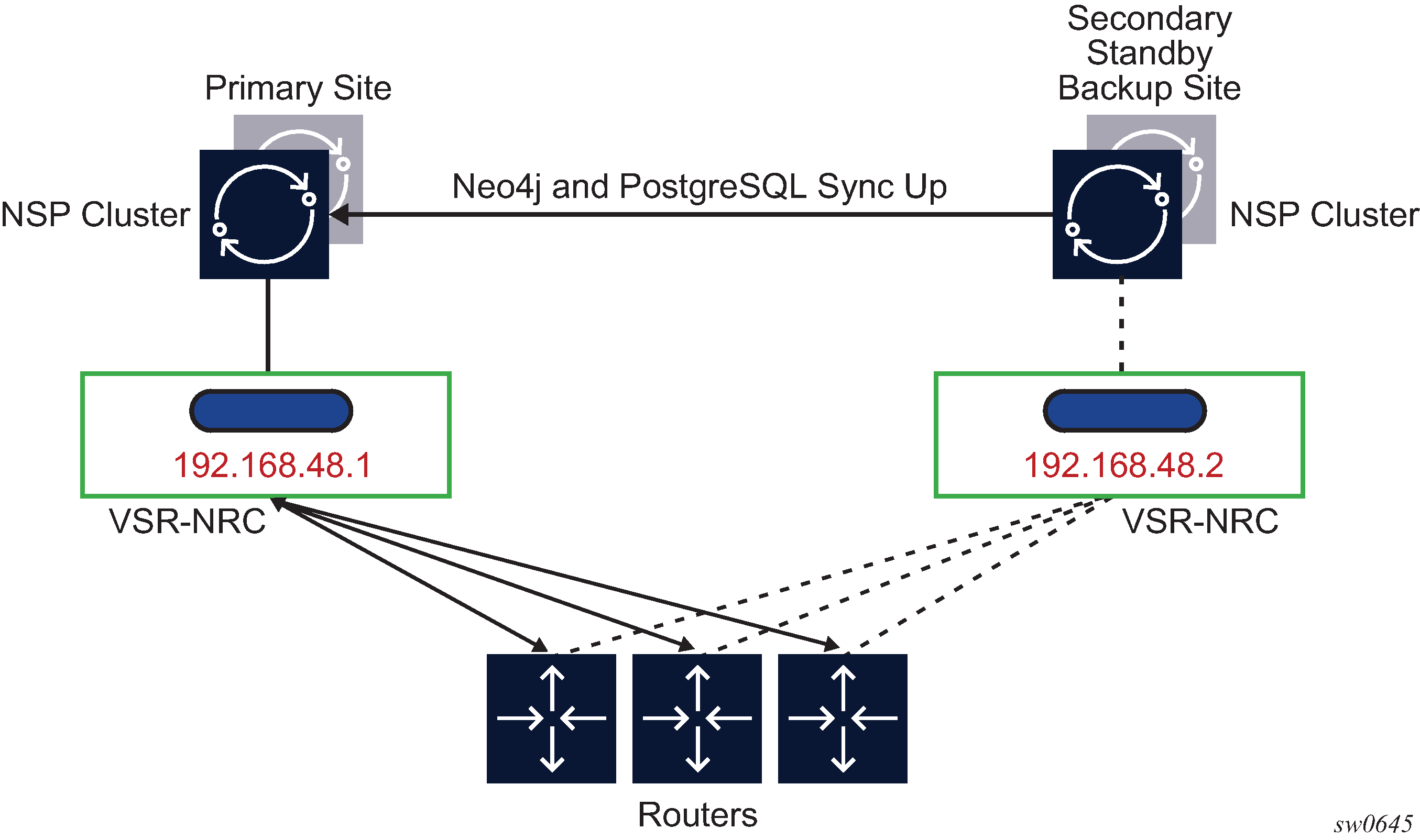
NSP ecosystem redundancy consists of two mechanisms that can be deployed separately or together:
High-Availability (HA) at a single site
the NSP, where the applications reside, is protected by a cluster of three Virtual Machines (VMs)
the VSR-NRC module, which implements PCEP, OpenFlow, and BGP-LS/IGP, does not support HA and is deployed with a single VM that contains the combined CPM and IOM codes
DR, which consists of a primary site and a secondary standby backup site. Each site consists of an NSP cluster and a VSR-NRC VM complex. A heartbeat protocol runs between the NSP clusters at the primary site and the standby backup site.
The VSR-NRC can be deployed as a standalone configuration; however, the NSP must be deployed in a cluster at each site. This configuration is also referred to as a 3+3 deployment.
Each parent NSP cluster establishes a reliable TCP session with a virtual IP to the local VSR-NRC. The TCP session runs an internal protocol, also known as cproto. This configuration is done prior to system startup and cannot be changed with an active NSP; the NSP must be shut down for any changes.
NSP Cluster Redundancy
The following describes NSP cluster redundancy rules.
At a single site, a master is elected among the cluster of three VMs. Between sites, a single cluster at one site is the primary/active site and the other DR site is the secondary/standby site.
The application processes at the standby site are shut down but the Neo4j and other databases are synchronized with the primary/active site.
Switching to the standby site can be initiated manually or by using an automated approach stemming from the loss of heartbeat between the primary and standby sites.
If the NSP cluster at the primary/active site is down (two out of three servers must be inactive, shut down, or failed), the heartbeat mechanism between the primary and standby NSP clusters fails after three timeouts. This initiates the active role at the secondary/standby site.
When the NSP cluster at the primary site is back up, the heartbeat mechanism between the primary/standby and secondary/active NSP clusters is restored. The primary site can be manually restored as the active site. Automatic reversion to the primary NSP cluster is not supported.
VSR-NRC Redundancy
The following describes VSR-NRC redundancy rules:
steady state behavior
The VSR-NRC at the secondary/standby site, in the same way as the VSR-NRC at the primary/active site, establishes PCEP sessions to the PCCs. However, the VSR-NRC at the standby site has its PCEP sessions to the PCCs in the overload state. The VSR-NRC enters this PCEP overload state when its upstream cproto session to the NSP cluster is down, resulting from either the NSP cluster going into the standby state or the cproto session failing.
The VSR-NRC acting as a PCE signals the overload state to the PCCs in a PCEP notification message. In the overload state, the VSR-NRC PCE accepts reports (PCRpt) without delegation but rejects requests (PCReq) and rejects reports (PCRpt) with delegation. The VSR-NRC PCE also does not originate initiate messages (PCInitiate) or update messages (PCUpd).
The VSR-NRC at the secondary/standby site maintains its BGP and IGP peerings with the network and updates its TE database as a result of any network topology changes.
primary/active NSP cluster failure
If the NSP cluster at the primary/active site is down (two out of three servers must be inactive, shut down, or failed), the heartbeat mechanism between the primary/active and secondary/standby NSP clusters fails. This initiates the NSP cluster activity at the secondary/standby site.
The following are the activities on the VSR-NRC.
The VSR-NRC at the primary site detects the cproto session failure and puts all its PCEP sessions to the PCCs into the overload state.
The NSP cluster at the secondary site establishes the cproto session to the local VSR-NRC, which then brings its PCEP sessions out of the overload state.
The VSR-NRC at the secondary site begins synchronizing the TE and LSP databases with the parent NSP cluster at the secondary site that is now the active site.
The VSR-NRC at the primary site must also return the delegation of all LSPs to the PCCs by sending an empty LSP Update Request that has the Delegate flag set to 0 as per RFC 8231. This allows the PCCs to delegate all eligible LSPs, including PCE-initiated LSPs, to the PCE function in the VSR-NRC at the secondary site.
Note: If the entire primary site fails, the above actions of the VSR-NRC at the primary site do not apply; however, the remaining actions do apply.VSR-NRC complex failure at the primary site (NSP server is still up)
A VSR-NRC complex failure at the primary/active NSP site does not initiate an NSP switchover to the secondary/standby NSP site. If the VSR-NRC at the primary site does not recover, a manual switchover to the secondary NSP site is required. The VSR-NRC failure causes a cproto session failure alarm to be raised on the NSP indicating that the NSP cannot communicate with the VSR-NRC. The operator can manually perform a switchover of the NSP activity to the secondary site.
PCC Behavior
The following describes rules for a PCC with PCE redundancy:
PCCs can establish upstream PCEP sessions with at most two VSR-NRC PCEs.
Each upstream session has a preference that takes effect when both upstream PCEP sessions are successfully established. The PCE peer that is not in overload is always selected by the PCC as the active PCE. However, if neither of the PCEs are signaling the overload state, the PCE with the higher numerical preference value is selected, and in case of a tie, the PCE with the lower IP address is selected.
In the steady state, because one upstream VSR-NRC PCE is in overload, only one PCEP session is active. The PCCs delegate an LSP using a report message (PCRpt) with the Delegate flag set to the active VSR-NRC PCE only. Request messages (PCReq) are not sent to the secondary/standby VSR-NRC PCE in overload. PCRpt messages are sent with the Delegate flag clear to the secondary/standby VSR-NRC PCE in overload.
If the current active PCEP session signals the overload state, the PCC will select the other PCE as the active PCE as long as the corresponding PCEP session is not in overload. Any new path request message (PCReq) or path report message (PCRpt) with the Delegate flag set is sent to the new PCE.
The PCE in overload should return the delegation of all existing LSPs to this PCC by sending an empty LSP Update Request that has the Delegate flag set as per RFC 8231. This PCC will then delegate these LSPs to the newly active PCE by sending a path report (PCRpt) with the Delegate flag set.
If the current active PCEP session goes operationally down, the PCC starts the redelegation timer (default is 90 s).
If the PCEP session is restored before the redelegation timer expires, no delegation change is performed and the LSP state is maintained.
Upon expiration of the redelegation timer, the PCC looks for the other PCEP session and, if not in overload, it immediately delegates the LSPs to the newly active PCE. If the new PCE accepts the delegation, the LSP state is maintained.
If the PCEP session does not recover before the redelegation timer expires and the PCC fails to find another active PCEP session, the state of LSPs by default are not cleared. The PCC does not clear the state of PCC-initiated LSPs; however, the user can do this by deleting the configuration.
Configuring RSVP-TE LSPs with PCEP Using the CLI
This section provides information about using the CLI to configure and operate RSVP-TE LSPs with PCEP.
The following information describes the detailed configuration of an inter-area RSVP-TE LSP with both a primary path and a secondary path. The network uses IS-IS with the backbone area in Level 2 and the leaf areas in Level 1. Topology discovery is learned by the NRC-P using IGP and the NSP NFM-P.
The LSP uses an admin-group constraint to keep the paths of the secondary and primary links disjoint in the backbone area. The LSP is PCE-controlled but also has path-computation-method pce enabled so that the initial path, and any MBB path, is also computed by the PCE.
The NSP and 7705 SAR load versions used to produce this example in this section are:
NSP: NSP-2.0.3-rel.108
PCE SROS: TiMOS-B-0.0.W129
PCC: TiMOS-B-0.0.I4902
This section provides configuration and show commands for the following examples:
PCEP on the PCE Node and the PCC Node
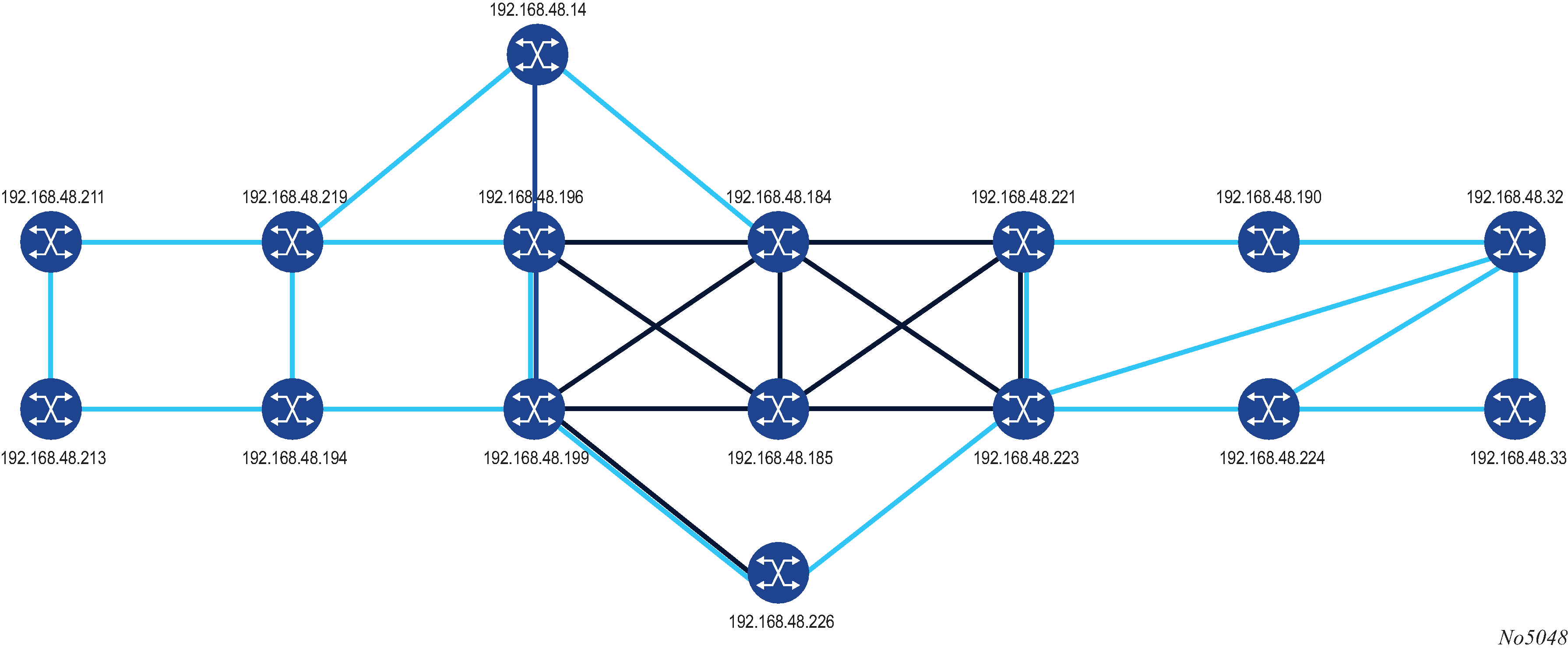
Multi-level IS-IS Topology in the NSP GUI shows a multi-level IS-IS topology in the NSP GUI.
The following example shows the configuration and show command output of the PCEP on the PCE node and the PCC node.
*A:PCE Server 226>config>router>pcep>pce# info
----------------------------------------------
            local-address 192.168.48.226
            no shutdown
----------------------------------------------
*A:Reno 194>config>router>pcep>pcc# info
----------------------------------------------
            peer 192.168.48.226
                no shutdown
            exit
            no shutdown
----------------------------------------------

*A:PCE Server 226>config>router>pcep>pce# show router pcep pce status
===============================================================================
Path Computation Element Protocol (PCEP) Path Computation Element (PCE) Info
===============================================================================
Admin Status           : Up              Oper Status          : Up
Unknown Msg Limit      : 10 msg/min
Keepalive Interval     : 30 seconds      DeadTimer Interval   : 120 seconds
Capabilities List      : stateful-delegate stateful-pce segment-rt-path
Local Address          : 192.168.48.226
PCE Overloaded         : false
-------------------------------------------------------------------------------
PCEP Path Computation Element (PCE) Peer Info
-------------------------------------------------------------------------------
Peer                       Sync State             Oper Keepalive/Oper DeadTimer
-------------------------------------------------------------------------------
192.168.48.190:4189        done                   30/120
192.168.48.194:4189        done                   30/120
192.168.48.198:4189        done                   30/120
192.168.48.199:4189        done                   30/120
192.168.48.219:4189        done                   30/120
192.168.48.221:4189        done                   30/120
192.168.48.224:4189        done                   30/120
-------------------------------------------------------------------------------
===============================================================================

*A:Reno 194# show router pcep pcc status
=======================================================================
Path Computation Element Protocol (PCEP) Path Computation Client (PCC) Info
=======================================================================
Admin Status           : Up              Oper Status          : Up
Unknown Msg Limit      : 10 msg/min
Keepalive Interval     : 30 seconds      DeadTimer Interval   : 120 seconds
Capabilities List      : stateful-delegate stateful-pce segment-rt-path
Address                : 192.168.48.194
Report Path Constraints: True
-----------------------------------------------------------------------
PCEP Path Computation Client (PCC) Peer Info
-----------------------------------------------------------------------
Peer                       Admin State/Oper State Oper Keepalive/Oper DeadTimer
-----------------------------------------------------------------------
192.168.48.226             Up/Up                  30/120
-----------------------------------------------------------------------
=======================================================================

*A:Reno 194# show router pcep pcc lsp-db
=======================================================================
PCEP Path Computation Client (PCC) LSP Update Info
=======================================================================
PCEP-specific LSP ID: 11
LSP ID              : 14378             LSP Type            : rsvp-p2p
Tunnel ID           : 1                 Extended Tunnel Id  : 192.168.48.194
LSP Name            : From Reno to Atlanta RSVP-TE::primary_empty
Source Address      : 192.168.48.194    Destination Address : 192.168.48.224
LSP Delegated       : True              Delegate PCE Address: 192.168.48.226
Oper Status         : active
-----------------------------------------------------------------------
PCEP-specific LSP ID: 12
LSP ID              : 14380             LSP Type            : rsvp-p2p
Tunnel ID           : 1                 Extended Tunnel Id  : 192.168.48.194
LSP Name            : From Reno to Atlanta RSVP-TE::secondary_empty
Source Address      : 192.168.48.194    Destination Address : 192.168.48.224
LSP Delegated       : True              Delegate PCE Address: 192.168.48.226
Oper Status         : up
=======================================================================
MPLS on the PCC Node
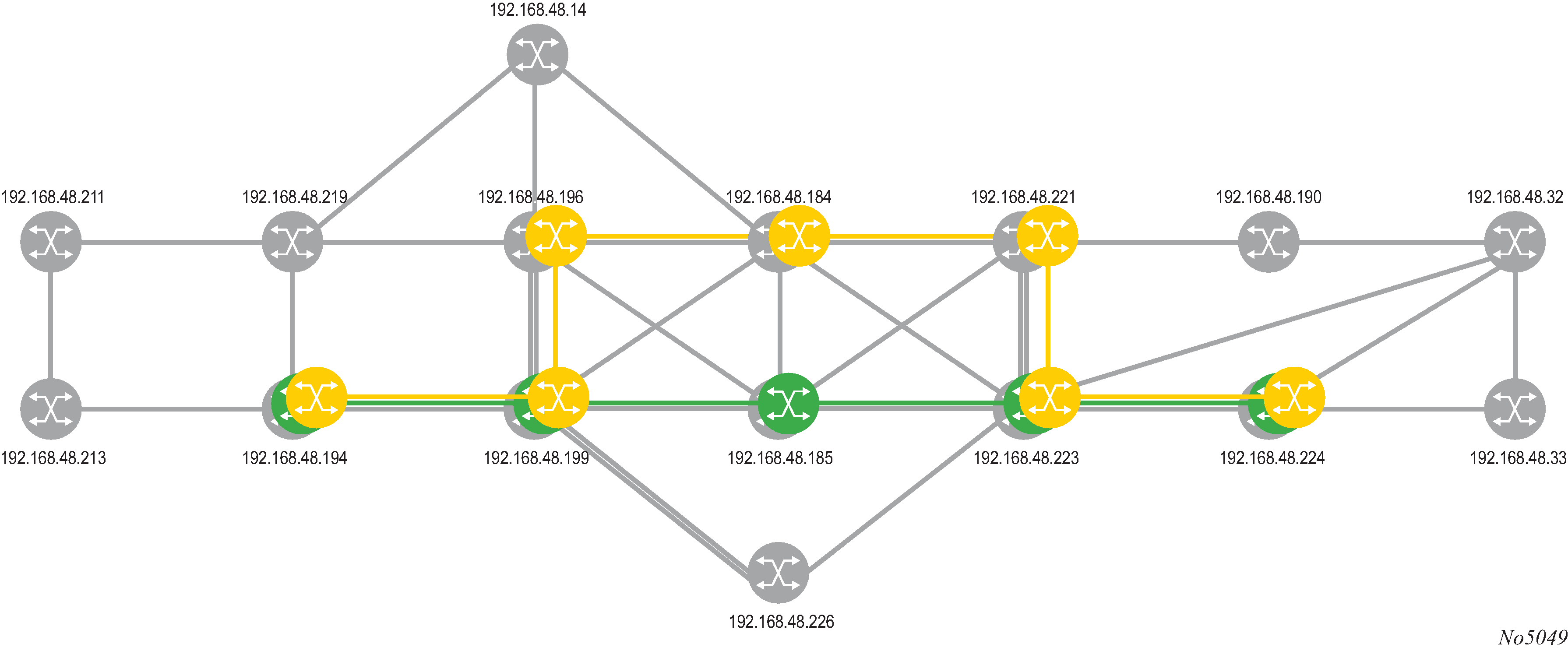
Primary and Secondary RSVP-TE LSP Paths in the NSP GUI shows primary and secondary RSVP-TE LSP paths in the NSP GUI.
The following example shows the configuration and show command output of the MPLS on the PCC node.
*A:Reno 194>config>router>mpls>lsp# info
----------------------------------------------
                to 192.168.48.224
                egress-statistics
                    shutdown
                exit
                cspf
                fast-reroute facility
                    no node-protect
                exit
                path-computation-method pce
                pce-report enable
                pce-control
                revert-timer 1
                primary "primary_empty"
                    exclude "top"
                    bandwidth 10
                exit
                secondary "secondary_empty"
                    standby
                    exclude "bottom"
                    bandwidth 5
                exit
                no shutdown
----------------------------------------------

*A:Reno 194# show router mpls lsp "From Reno to Atlanta RSVP-TE" path detail
===============================================================================
MPLS LSP From Reno to Atlanta RSVP-TE Path  (Detail)
===============================================================================
Legend :
    @ - Detour Available              # - Detour In Use
    b - Bandwidth Protected           n - Node Protected
    s - Soft Preemption
    S - Strict                        L - Loose
    A - ABR
===============================================================================
-------------------------------------------------------------------------------
LSP From Reno to Atlanta RSVP-TE Path primary_empty
-------------------------------------------------------------------------------
LSP Name         : From Reno to Atlanta RSVP-TE
Path LSP ID      : 14382
From             : 192.168.48.194       To                   : 192.168.48.224
Admin State      : Up                   Oper State           : Up
Path Name        : primary_empty        Path Type            : Primary
Path Admin       : Up                   Path Oper            : Up
Out Interface    : 1/1/1                Out Label            : 262094
Path Up Time     : 0d 00:00:22          Path Down Time       : 0d 00:00:00
Retry Limit      : 0                    Retry Timer          : 30 sec
Retry Attempt    : 0                    Next Retry In        : 0 sec
BFD Template     : None                 BFD Ping Interval    : 60
BFD Enable       : False
Adspec           : Disabled             Oper Adspec          : Disabled
CSPF             : Enabled              Oper CSPF            : Enabled
Least Fill       : Disabled             Oper LeastFill       : Disabled
FRR              : Enabled              Oper FRR             : Enabled
FRR NodeProtect  : Disabled             Oper FRR NP          : Disabled
FR Hop Limit     : 16                   Oper FRHopLimit      : 16
FR Prop Admin Gr*: Disabled             Oper FRPropAdmGrp    : Disabled
Propogate Adm Grp: Disabled             Oper Prop Adm Grp    : Disabled
Inter-area       : False
PCE Updt ID      : 0
PCE Report       : Enabled              Oper PCE Report      : Enabled
PCE Control      : Enabled              Oper PCE Control     : Enabled
PCE Compute      : Enabled
Neg MTU          : 1496                 Oper MTU             : 1496
Bandwidth        : 10 Mbps              Oper Bandwidth       : 10 Mbps
Hop Limit        : 255                  Oper HopLimit        : 255
Record Route     : Record               Oper Record Route    : Record
Record Label     : Record               Oper Record Label    : Record
Setup Priority   : 7                    Oper Setup Priority  : 7
Hold Priority    : 0                    Oper Hold Priority   : 0
Class Type       : 0                    Oper CT              : 0
Backup CT        : None
MainCT Retry     : n/a
    Rem          :
MainCT Retry     : 0
    Limit        :
Include Groups   :                      Oper Include Groups  :
None                                           None
Exclude Groups   :                      Oper Exclude Groups  :
top                                            top
Adaptive         : Enabled              Oper Metric          : 40
Preference       : n/a
Path Trans       : 7                    CSPF Queries         : 7172
Failure Code     : noError
Failure Node     : n/a
Explicit Hops    :
    No Hops Specified
Actual Hops      :
    10.202.5.194 (192.168.48.194) @               Record Label        : N/A
 -> 10.202.5.199 (192.168.48.199) @               Record Label        : 262094
 -> 192.168.48.185 (192.168.48.185)               Record Label        : 262111
 -> 10.0.5.185                                    Record Label        : 262111
 -> 192.168.48.223 (192.168.48.223)               Record Label        : 262121
 -> 10.0.7.223                                    Record Label        : 262121
 -> 192.168.48.224 (192.168.48.224)               Record Label        : 262116
 -> 10.101.4.224                                  Record Label        : 262116
Computed Hops    :
    10.202.5.199(S)
 -> 10.0.5.185(S)
 -> 10.0.7.223(S)
 -> 10.101.4.224(S)
Resignal Eligible: False
Last Resignal    : n/a                  CSPF Metric          : 40
-------------------------------------------------------------------------------
LSP From Reno to Atlanta RSVP-TE Path secondary_empty
-------------------------------------------------------------------------------
LSP Name         : From Reno to Atlanta RSVP-TE
Path LSP ID      : 14384
From             : 192.168.48.194       To                   : 192.168.48.224
Admin State      : Up                   Oper State           : Up
Path Name        : secondary_empty      Path Type            : Standby
Path Admin       : Up                   Path Oper            : Up
Out Interface    : 1/1/1                Out Label            : 262091
Path Up Time     : 0d 00:00:25          Path Down Time       : 0d 00:00:00
Retry Limit      : 0                    Retry Timer          : 30 sec
Retry Attempt    : 0                    Next Retry In        : 0 sec
BFD Template     : None                 BFD Ping Interval    : 60
BFD Enable       : False
Adspec           : Disabled             Oper Adspec          : Disabled
CSPF             : Enabled              Oper CSPF            : Enabled
Least Fill       : Disabled             Oper LeastFill       : Disabled
Propogate Adm Grp: Disabled             Oper Prop Adm Grp    : Disabled
Inter-area       : False
PCE Updt ID      : 0
PCE Report       : Enabled              Oper PCE Report      : Enabled
PCE Control      : Enabled              Oper PCE Control     : Enabled
PCE Compute      : Enabled
Neg MTU          : 1496                 Oper MTU             : 1496
Bandwidth        : 5 Mbps               Oper Bandwidth       : 5 Mbps
Hop Limit        : 255                  Oper HopLimit        : 255
Record Route     : Record               Oper Record Route    : Record
Record Label     : Record               Oper Record Label    : Record
Setup Priority   : 7                    Oper Setup Priority  : 7
Hold Priority    : 0                    Oper Hold Priority   : 0
Class Type       : 0                    Oper CT              : 0
Include Groups   :                      Oper Include Groups  :
None                                           None
Exclude Groups   :                      Oper Exclude Groups  :
bottom                                         bottom
Adaptive         : Enabled              Oper Metric          : 60
Preference       : 255
Path Trans       : 28                   CSPF Queries         : 10
Failure Code     : noError
Failure Node     : n/a
Explicit Hops    :
    No Hops Specified
Actual Hops      :
    10.202.5.194 (192.168.48.194)                 Record Label        : N/A
 -> 10.202.5.199 (192.168.48.199)                 Record Label        : 262091
 -> 10.0.9.198 (192.168.48.198)                   Record Label        : 262096
 -> 192.168.48.184 (192.168.48.184)               Record Label        : 262102
 -> 10.0.2.184                                   Record Label        : 262102
 -> 192.168.48.221 (192.168.48.221)               Record Label        : 262119
 -> 10.0.4.221                                   Record Label        : 262119
 -> 192.168.48.223 (192.168.48.223)               Record Label        : 262088
 -> 10.0.10.223                                  Record Label        : 262088
 -> 192.168.48.224 (192.168.48.224)               Record Label        : 262115
 -> 10.101.4.224                                 Record Label        : 262115
Computed Hops    :
    10.202.5.199(S)
 -> 10.0.9.198(S)
 -> 10.0.2.184(S)
 -> 10.0.4.221(S)
 -> 10.0.10.223(S)
 -> 10.101.4.224(S)
Srlg             : Disabled
Srlg Disjoint    : False
Resignal Eligible: False
Last Resignal    : n/a                  CSPF Metric          : 60
===============================================================================
The following CLI displays are output examples of a PCEP SR-TE LSP in three configurations:
-
PCE-computation enabled, PCE-report disabled (via inheritance), and PCE-control disabled
-
PCE-computation enabled, PCE-report enabled, and PCE-control disabled
-
PCE-computation enabled, PCE-report enabled, and PCE-control enabled
The configuration can be determined by checking the PCE Report, PCE Compute, and PCE Control fields. An example of the output is shown below. For more information and CLI output examples, see the show>router>mpls>sr-te-lsp command description.
*A:7705:Dut-C# show  router mpls sr-te-lsp detail
===============================================================================
MPLS SR-TE LSPs (Originating) (Detail)
===============================================================================
-------------------------------------------------------------------------------
Type : Originating
-------------------------------------------------------------------------------
LSP Name        : test_lsp_1
LSP Type        : SrTeLsp                   LSP Tunnel ID        : 1
LSP Index       : 65536                     TTM Tunnel Id        : 655362
From            : 10.20.1.3                 To                   : 10.20.1.4
Adm State       : Up                        Oper State           : Up
LSP Up Time     : 0d 00:00:44               LSP Down Time        : 0d 00:00:00
Transitions     : 1                         Path Changes         : 1
Retry Limit     : 0                         Retry Timer          : 30 sec
Hop Limit       : 255                       Negotiated MTU       : 1492
CSPF            : Enabled
Metric          : N/A                       Use TE metric        : Disabled
Include Grps    :                           Exclude Grps         :
None                                           None

VprnAutoBind    : Enabled
IGP Shortcut    : Enabled
IGP LFA         : Disabled                  IGP Rel Metric       : Disabled
BGPTransTun     : Enabled
Oper Metric     : 100
PCE Report      : Inherited
PathCompMethod  : pce                       PCE Control          : Disabled
Max SR Labels   : 6                         Additional FRR Labels: 1
Path Profile    :
None

Primary(a)      : fully_loose               Up Time              : 0d 00:00:44
Bandwidth       : 0 Mbps
===============================================================================
*A:7705:Dut-C#
PCEP Configuration Command Reference
Command Hierarchies
PCEP Commands
config
    - router
        - [no] pcep
            - [no] pcc
                - dead-timer seconds
                - no dead-timer
                - keepalive seconds
                - no keepalive
                - local-address ip-address
                - no local-address
                - pce-associations
                    - [no] diversity association-name
                        - association-id association-id
                        - no association-id
                        - association-source ip-address
                        - no association-source
                        - [no] disjointness-reference
                        - disjointness-type {loose | strict}
                        - no disjointness-type
                        - diversity-type {link | node | srlg-link | srlg-node}
                        - no diversity-type
                    - [no] policy association-name
                        - association-id association-id
                        - no association-id
                        - association-source ip-address
                        - no association-source
                - peer ip-address [preference preference]
                - no peer ip-address
                    - route-preference {both | inband | outband}
                    - [no] route-preference
                    - [no] shutdown
                    - tls-client-profile profile-name
                    - no tls-client-profile
                    - tls-wait-timer [60..255]
                    - no tls-wait-timer
                - redelegation-timer seconds
                - no redelegation-timer
                - [no] report-path-constraints
                - [no] shutdown
                - unknown-message-rate msg/min
                - no unknown-message-rate
Show Commands
show
    - router
        - pcep
            - pcc
                - detail
                - lsp-db [lsp-type lsp-type] [delegated-pce ip-address]
                - lsp-db [lsp-type lsp-type] from ip-address [delegated-pce ip-address]
                - lsp-db [lsp-type lsp-type] lsp lsp-name [delegated-pce ip-address]
                - lsp-db [lsp-type lsp-type] to ip-address [tunnel-id [tunnel-id]]
                - lsp-db [lsp-type lsp-type] tunnel-id [tunnel-id]
                - path-request [lsp-type {rsvp-p2p}] [dest ip-address] [detail]
                - pce-associations
                    - diversity [diversity-assoc-name]
                    - policy [policy-assoc-name]
                - peer [ip-address] [detail]
                - status
Command Descriptions
PCEP Commands
pcep
Syntax
[no] pcep
Context
config>router
Description
This command enables the Path Computation Element Communication Protocol (PCEP) and enters the context to configure PCEP parameters.
The no form of the command disables PCEP.
pcc
Syntax
[no] pcc
Context
config>router>pcep
Description
This command enables the context to configure PCC parameters.
dead-timer
Syntax
dead-timer seconds
no dead-timer
Context
config>router>pcep>pcc
Description
This command configures the PCEP session dead timer value, which is the amount of time a PCEP speaker will wait after the receipt of the last PCEP message before declaring its peer down.
The dead timer mechanism is asymmetric, meaning that each PCEP speaker can propose a different dead timer value to its peer to use to detect session timeout.
The no form of the command returns the dead timer to the default value.
Default
120
Parameters
- seconds
-
the dead timer value, in seconds
keepalive
Syntax
keepalive seconds
no keepalive
Context
config>router>pcep>pcc
Description
This command configures the PCEP session keepalive value. A PCEP speaker must send a keepalive message if no other PCEP message is sent to the peer at the expiry of this timer. This timer is restarted every time a PCEP message or keepalive message is sent.
The keepalive mechanism is asymmetric, meaning that each peer can use a different keepalive timer value at its end.
The no form of the command returns the keepalive timer to the default value.
Default
30
Parameters
- seconds
-
the keepalive value, in seconds
local-address
Syntax
local-address ip-address
no local-address
Context
config>router>pcep>pcc
Description
This command configures the local address of the PCEP speaker.
The PCEP protocol operates over TCP using destination TCP port 4189. The PCE client (PCC) always initiates the connection. When the user configures the PCEP local address and the peer address on the PCC, the PCC initiates a TCP connection to the PCE. When the connection is established, the PCC and PCE exchange OPEN messages, which initializes the PCEP session and exchanges the session parameters to be negotiated.
By default, the PCC checks first to determine if the remote PCE address is reachable out-of-band via the management port. If the remote address is not reachable, the PCC will check if the remote PCE address is reachable in-band. The local address configured by the user is only used for in-band sessions and is otherwise ignored. When the session comes up out-of-band, the system IP address is always used as the local address. Use the route-preference command to configure the PCC to use only out-of-band or only in-band instead.
The no form of the command removes the configured local address of the PCEP speaker.
Parameters
- ip-address
-
the IP address of the PCEP speaker to be used for in-band sessions
pce-associations
Syntax
pce-associations
Context
config>router>pcep>pcc
Description
This command enables the context to configure PCEP association groups.
Default
n/a
diversity
Syntax
[no] diversity association-name
Context
config>router>pcep>pcc>pce-assoc
Description
This command creates a diversity association, and enables the context to create diversity association parameters .
The no form of the command deletes the diversity association.
Default
n/a
Parameters
- association-name
-
the name of the diversity association, up to 32 characters
association-id
Syntax
association-id association-id
no association-id
Context
config>router>pcep>pcc>pce-assoc>div
config>router>pcep>pcc>pce-assoc>plcy
Description
This command configures the diversity or policy Association ID. The user must specify an Association ID. The ID value is interpreted as a global value independent of the IP address of the PCC node that uses it to associate LSPs.
The Association ID for the diversity type supports the user-configured mode of operation, as defined in RFC 8800.
The no form of the command removes the Association ID from the diversity or policy association.
Default
no association-id
Parameters
- association-id
-
specifies the diversity or policy Association ID
association-source
Syntax
association-source ip-address
no association-source
Context
config>router>pcep>pcc>pce-assoc>div
config>router>pcep>pcc>pce-assoc>plcy
Description
This command configures the source IP address of the diversity or policy association.
The no form of the command removes the IP address from the diversity or policy association.
Default
no association-source
Parameters
- ip-address
-
the source IP address
disjointness-reference
Syntax
[no] disjointness-reference
Context
config>router>pcep>pcc>pce-assoc>div
Description
This command sets the P-flag in the DISJOINTNESS-CONFIGURATION TLV. When enabled, it indicates that this LSP path is the reference path for the disjoint set of paths. The PCE must first compute the path of this LSP and then apply the configured disjointness type to compute the paths of all other LSPs in the same diversity Association ID.
The no form of the command sets the P-flag to false.
Default
no disjointness-reference
disjointness-type
Syntax
disjointness-type {loose | strict}
no disjointness-type
Context
config>router>pcep>pcc>pce-assoc>div
Description
This command sets the T-flag in the DISJOINTNESS-CONFIGURATION TLV.
When the disjointness type is configured as strict, the T-flag is set in the DISJOINTNESS-CONFIGURATION TLV and the PCE will send a reply with no path if it is not able to provide a set of disjoint paths for one or more LSPs in the association.
When the disjointness type is configured as loose, the T-flag is not set in the DISJOINTNESS-CONFIGURATION TLV and the PCE is allowed to relax the disjointness constraint in order to return paths for the LSPs.
The no form of the command reverts to the default value.
Default
loose
Parameters
- loose
-
specifies the loose disjointness type
- strict
-
specifies the strict disjointness type
diversity-type
Syntax
diversity-type {link | node | srlg-link | srlg-node}
no diversity-type
Context
config>router>pcep>pcc>pce-assoc>div
Description
This command configures the diversity type for the association group. This command is mandatory. If the command is not configured, the system does not validate the association configuration.
The no form of the command reverts to the default value.
Default
no diversity-type
Parameters
- link
-
specifies the link diversity type
- node
-
specifies the node diversity type
- srlg-link
-
specifies the SRLG link diversity type
- srlg-node
-
specifies the SRLG node diversity type
policy
Syntax
[no] policy association-name
Context
config>router>pcep>pcc>pce-assoc
Description
This command creates a PCE policy association and enables the context to create policy association parameters.
The no form of the command deletes the policy association.
Default
n/a
Parameters
- association-name
-
the name of the policy association, up to 32 characters
peer
Syntax
peer ip-address [preference preference]
no peer ip-address
Context
config>router>pcep>pcc
Description
This command configures the IP address of a peer PCEP speaker. The address is used as the destination address in the PCEP session messages to a PCEP peer.
The preference parameter allows the PCC to select the preferred PCE when both have PCEP sessions successfully established. A maximum of two PCEP peers is supported. The PCE peer that is not in overload is always selected by the PCC as the active PCE; however, if neither of the PCEs are signaling the overload state, the PCE with the lower IP address is selected.
The no form of the command removes the specified peer PCEP speaker.
Parameters
- ip-address
-
the IP address of the PCEP peer to be used as the destination address in the PCEP session
- preference
-
specifies the preference value of the peer
redelegation-timer
Syntax
redelegation-timer seconds
no redelegation-timer
Context
config>router>pcep>pcc
Description
This command configures the redelegation timer for PCE-initiated LSPs.
The no form of this command sets this value to the default.
Default
90
Parameters
- seconds
- specifies the number of seconds before the redelegation timer expires
route-preference
Syntax
route-preference {both | inband | outband}
no route-preference
Context
config>router>pcep>pcc>peer
Description
This command configures the route preference that PCC uses to reach the remote PCE address, which allows you to restrict the PCC to using only out-of-band or only in-band for reachability. By default, the PCC checks first to determine if the remote PCE address is reachable out-of-band via the management port. If the remote address is not reachable, the PCC will try to reach the remote PCE address in-band.
The no form of this command resets the route preference to the default behavior.
Default
both
Parameters
- both
-
the PCC uses the out-of-band routing table to reach the PCC; if unsuccessful, it then uses the in-band routing table
- inband
-
the PCC uses only the in-band routing table to attempt to reach the PCE
- outband
-
the PCC uses only the out-of-band management router routing table to attempt to reach the PCE
report-path-constraints
Syntax
[no] report-path-constraints
Context
config>router>pcep>pcc
Description
This command enables the inclusion of LSP path constraints in the PCE report messages sent from the PCC to a PCE.
In order for the PCE to know about the original constraints for an LSP that is delegated but for which there is no prior state in its LSP database; for example, if no PCReq message was sent for the same PLSP-ID, the following proprietary behavior is observed:
-
the PCC appends a duplicate of each of the LSPA, metric, and bandwidth objects in the PCRpt message. The only difference between two objects of the same type is that the P-flag is set in the common header of the duplicate object to indicate that it is a mandatory object for processing by the PCE.
-
the value of the metric or bandwidth in the duplicate object contains the original constraint value, while the first object contains the operational value. This is applicable to hop metrics in the metric and bandwidth objects only. The 7705 SAR PCC does not support configuring a boundary on the path computation IGP or TE metrics.
-
the path computation on the PCE must use the first set of objects when updating a path if the PCRpt message contained a single set. If the PCRpt message contained a duplicate set, PCE path computation must use the constraints in the duplicate set.
The no form of the command disables the above behavior in case of interoperability issues with third-party PCE implementations.
Default
report-path-constraints
shutdown
Syntax
[no] shutdown
Context
config>router>pcep>pcc
config>router>pcep>pcc>peer
Description
This command administratively disables the PCC process.
The following PCC parameters can be modified without shutting down the PCEP session:
-
report-path-constraints
-
unknown-message-rate
The following PCC parameters can only be modified when the PCEP session is shut down:
-
local-address
-
keepalive
-
dead-timer
-
peer
Default
shutdown
tls-client-profile
Syntax
tls-client-profile profile-name
no tls-client-profile
Context
config>router>pcep>pcc>peer
Description
This command configures a TLS client profile on the PCC. When the TLS client profile is configured, the PCC tries to establish a PCEP connection with the PCE over TLS. If the PCE sends an Open message or does not send back a StartTLS message within the time set by the tls-wait-timer command, the connection is not accepted and the TCP connection is closed and a new connection is tried within 60 s
The no form of the command removes TLS encryption from the communication between the PCC and the PCE.
Default
no tls-client-profile
Parameters
- profile-name
-
the TLS client profile name, up to 32 characters in length
tls-wait-timer
Syntax
tls-wait-timer [60..255]
no tls-wait-timer
Context
config>router>pcep>pcc>peer
Description
This command configures the time that the PCC waits before declaring a TLS handshake failure if the handshake is not established.
The no form of the command reverts to the default.
Default
tls-wait-timer 60
Parameters
- [60..255]
-
the wait time in seconds
- Values: 60 to 255
unknown-message-rate
Syntax
unknown-message-rate msg/min
no unknown-message-rate
Context
config>router>pcep>pcc
Description
This command configures the maximum rate of unknown messages that can be received during a PCEP session.
When the rate of received unrecognized or unknown messages reaches the configured limit, the PCEP speaker closes the session to the peer.
The no form of the command returns the unknown message rate to the default value.
Default
10
Parameters
- msg/min
-
the rate of unknown messages, in messages per minute
Show Commands
detail
Syntax
detail
Context
show>router>pcep>pcc
Description
This command displays PCEP PCC detailed information.
Output
The following output is an example of PCEP PCC detailed information, and PCEP PCC Field Descriptions describes the fields.
Output Example*A:Sar18 Dut-B>show>router>pcep# pcc detail
===============================================================================
Path Computation Element Protocol (PCEP) Path Computation Client (PCC) Info
===============================================================================
Admin Status : Down Oper Status : Down
Unknown Msg Limit : 10 msg/min
Keepalive Interval : 50 seconds DeadTimer Interval : 150 seconds
Capabilities List : stateful-delegate stateful-pce rsvp-path
Address : 10.10.10.10
Report Path Constraints: True
Open Wait Timer : 60 seconds Keep Wait Timer : 60 seconds
Sync Timer : 60 seconds Request Timer : 120 seconds
Connection Timer : 60 seconds Allow Negotiations : False
Max Sessions : 1 Max Unknown Req : 1000
===============================================================================
*A:Sar18 Dut-B>show>router>pcep#
|
Label |
Description |
|---|---|
|
Admin Status |
The administrative status of the PCC |
|
Oper Status |
The operational status of the PCC |
|
Unknown Msg Limit |
The maximum rate of unknown messages that can be received on a PCEP session |
|
Keepalive Interval |
The specified keepalive interval for the PCEP session |
|
DeadTimer Interval |
The specified dead time interval for the PCEP session |
|
Capabilities List |
The capabilities list for the PCEP session |
|
Address |
The local IP address of the PCEP speaker |
|
Report Path Constraints |
Indicates whether to include LSP path constraints in the PCE report messages sent from the PCC to a PCE |
|
Open Wait Timer |
The value of the open wait timer for the PCEP session |
|
Keep Wait Timer |
The value of the keep wait timer for the PCEP session |
|
Sync Timer |
The value of the synchronization timer for the PCEP session |
|
Request Timer |
The value of the request timer for the PCEP session |
|
Connection Timer |
The value of the keep wait timer for the PCEP session |
|
Allow Negotiations |
Indicates where negotiations between PCEP PCC and PCE are allowed |
|
Max Sessions |
The maximum number of PCEP sessions on the router |
|
Max Unknown Req |
The maximum number of unknown requests for PCEP sessions on the router |
lsp-db
Syntax
lsp-db [lsp-type lsp-type] [delegated-pce ip-address]
lsp-db [lsp-type lsp-type] from ip-address [delegated-pce ip-address]
lsp-db [lsp-type lsp-type] lsp lsp-name [delegated-pce ip-address]
lsp-db [lsp-type lsp-type] to ip-address [tunnel-id [tunnel-id]]
lsp-db [lsp-type lsp-type] tunnel-id [tunnel-id]
Context
show>router>pcep>pcc
Description
This command displays PCEP PCC LSP information.
Parameters
- lsp-type
-
specifies the type of LSP to display. The only available option is RSVP-TE point-to-point LSPs (rsvp-p2p).
- tunnel-id
-
specifies a tunnel ID
- ip-address
-
specifies an IPv4 address
Output
The following output is an example of PCEP PCC LSP information.
Output Example*A:7705:Dut-C# show router pcep pcc lsp-db
===============================================================================
PCEP Path Computation Client (PCC) LSP Update Info
===============================================================================
PCEP-specific LSP ID: 1
LSP ID : 21504 LSP Type : rsvp-p2p
Tunnel ID : 1 Extended Tunnel Id : 10.20.1.3
LSP Name : test_lsp::fully_loose
Source Address : 10.20.1.3 Destination Address : 10.20.1.1
LSP Delegated : True Delegate PCE Address: 192.120.210.36
Oper Status : active
-------------------------------------------------------------------------------
PCEP-specific LSP ID: 2
LSP ID : 21510 LSP Type : rsvp-p2p
Tunnel ID : 1 Extended Tunnel Id : 10.20.1.3
LSP Name : test_lsp::stdby_fully_loose_2
Source Address : 10.20.1.3 Destination Address : 10.20.1.1
LSP Delegated : True Delegate PCE Address: 192.120.210.36
Oper Status : up
===============================================================================
*A:7705:Dut-C#
path-request
Syntax
path-request [lsp-type {rsvp-p2p}] [dest ip-address] [detail]
Context
show>router>pcep>pcc
Description
This command displays PCEP PCC path request information.
Parameters
- lsp-type
-
specifies the type of LSP to display. The only available option is RSVP-TE point-to-point LSPs.
- ip-address
-
specifies the destination IPv4 address to display
- detail
-
displays detailed path request information
Output
The following output is an example of PCEP PCC path request information.
Output Example*A:7705:Dut-C# show router pcep pcc path-request
===============================================================================
PCEP Path Computation Client (PCC) Path Computation Request (PCReq) Info
===============================================================================
Request ID : 4 Message State : sent-for-compute
Tunnel ID : 2 Extended Tunnel Id : 10.20.1.3
LSP ID : 62468 LSP Type : rsvp-p2p
LSP Name : test_lsp::fully_loose
Source Address : 10.20.1.3 Destination Address: 10.20.1.1
SVEC Id : 4 LSP Bandwidth : 0
===============================================================================
diversity
Syntax
diversity [diversity-assoc-name]
Context
show>router>pcep>pcc>pce-assoc
Description
This command displays the diversity association information for a PCEP diversity association group.
If a diversity association name is not specified, the information for all configured diversity associations is displayed.
Parameters
- diversity-assoc-name
-
the diversity association name
Output
The following output is an example of PCEP diversity association information, and PCEP Diversity Association Field Descriptions describes the output fields.
Output Example*A:Dut-C>config>router>mpls>lsp# show router pcep pcc pce-associations diversity "test_div"
===============================================================================
PCEP PCC Diversity Associations Info
===============================================================================
Assocation Name : test_div
Association ID : 20 Association Source : 192.168.213.59
Diversity Type : link Disjointness Type : loose
Disjoint Reference : False
===============================================================================|
Label |
Description |
|---|---|
| Association Name | The diversity association name |
| Association ID | The diversity association ID |
| Association Source | The source IP address of the diversity association |
| Diversity Type | The diversity type for the diversity association: association: link, node, srlg-link, or srlg-node |
| Disjointness Type | The disjointness type for the diversity association: loose or strict |
| Disjoint Reference | Indicates whether the P-flag is set in the DISJOINTNESS CONFIGURATION TLV; false means that the flag is not set |
policy
Syntax
policy [policy-assoc-name]
Context
show>router>pcep>pcc>pce-assoc
Description
This command displays the policy association information for a PCEP policy association group.
If a policy association name is not specified, the information for all configured policy associations is displayed.
Parameters
- policy-assoc-name
-
the policy association name
Output
The following output is an example of PCEP policy association information, and PCEP Policy Association Field Descriptions describes the output fields.
Output Example*A:Dut-C>config>router>mpls>lsp# show router pcep pcc pce-associations policy "test_pol"
===============================================================================
PCEP PCC Policy Associations Info
===============================================================================
Assocation Name : test_pol
Association ID : 10 Association Source : 192.168.213.59
===============================================================================|
Label |
Description |
|---|---|
| Association Name | The policy association name |
| Association ID | The policy association ID |
| Association Source | The source IP address of the policy association |
peer
Syntax
peer [ip-address] [detail]
Context
show>router>pcep>pcc
Description
This command displays PCEP PCC peer information.
Parameters
- ip-address
-
specifies a peer IPv4 address to display
- detail
-
displays detailed peer information
Output
The following output is an example of a PCEP PCC peer information, and PCEP PCC Peer Field Descriptions describes the fields.
Output Example*A:Sar18 Dut-B>show>router>pcep>pcc# peer detail
===============================================================================
PCEP Path Computation Client (PCC) Peer Info
===============================================================================
IP Address : 10.10.10.11
Admin Status : Down Oper Status : Down
Peer Capabilities : (Not Specified)
Speaker ID : (Undefined)
Sync State : not-initialized Peer Overloaded : False
Session Establish Time: 0d 00:00:00
Oper Keepalive : N/A Oper DeadTimer : N/A
Session Setup Count : 0 Session Setup Fail Count: 0
-------------------------------------------------------------------------------
Statistics Information
-------------------------------------------------------------------------------
Sent Received
-------------------------------------------------------------------------------
PC Request Message 0 0
PC Reply Message 0 0
PC Error Message 0 0
PC Notification Message 0 0
PC Keepalive Message 0 0
PC Update Message 0 0
PC Report Message 0 0
Path Report 0 0
Path Request 0 0
-------------------------------------------------------------------------------
===============================================================================
*A:Sar18 Dut-B>show>router>pcep>pcc#
|
Label |
Description |
|---|---|
|
IP Address |
The IP address of the PCC peer |
|
Admin Status |
The administrative status of the PCC peer |
|
Oper Status |
The operational status of the PCC peer |
|
Peer Capabilities |
The PCEP capabilities of the PCC peer |
|
Speaker ID |
The IP address of the PCC peer speaker |
|
Sync State |
The synchronization state of the |
|
Peer Overloaded |
Indicates whether the PCC peer is overloaded |
|
Session Establish Time |
The length of time since the PCEP session was established |
|
Oper Keepalive |
The operational value for the PCC peer keepalive timer |
|
Oper DeadTimer |
The operational value for the PCC peer dead timer |
|
Session Setup Count |
The number of times that the PCEP session has been set up |
|
Session Setup Fail Count |
The number of times that the PCEP session failed to be set up |
|
Statistics Information |
|
|
PC Request Message |
The number of path computation (PC) request messages sent the PCC peer and received from the PCC peer |
|
PC Reply Message |
The number of PC reply messages sent to the PCC peer and received from the PCC peer |
|
PC Error Message |
The number of PC error messages sent to the PCC peer and received from the PCC peer |
|
PC Notification Message |
The number of PC notification messages sent to the PCC peer and received from the PCC peer |
|
PC Keepalive Message |
The number of PC keepalive messages sent to the PCC peer and received from the PCC peer |
|
PC Update Message |
The number of PC update messages sent to the PCC peer and received from the PCC peer |
|
PC Report Message |
The number of PC report messages sent to the PCC peer and received from the PCC peer |
|
Path Report |
The number of path reports sent to the PCC peer and received from the PCC peer |
|
Path Request |
The path requests sent to the PCC peer and received from the PCC peer |
status
Syntax
status
Context
show>router>pcep>pcc
Description
This command displays PCEP PCC status information.
Output
The following output is an example of a PCEP PCC status information, and PCEP PCC Status Field Descriptions describes the fields.
Output Example*A:Sar18 Dut-B>show>router>pcep>pcc# status
===============================================================================
Path Computation Element Protocol (PCEP) Path Computation Client (PCC) Info
===============================================================================
Admin Status : Down Oper Status : Down
Unknown Msg Limit : 10 msg/min
Keepalive Interval : 50 seconds DeadTimer Interval : 150 seconds
Capabilities List : stateful-delegate stateful-pce rsvp-path
Address : 10.10.10.10
Report Path Constraints: True
-------------------------------------------------------------------------------
PCEP Path Computation Client (PCC) Peer Info
-------------------------------------------------------------------------------
Peer Admin State/Oper State Oper Keepalive/Oper DeadTimer
-------------------------------------------------------------------------------
10.10.10.11 Down/Down Not-Applicable/Not-Applicable
-------------------------------------------------------------------------------
===============================================================================
*A:Sar18 Dut-B>show>router>pcep>pcc#
|
Label |
Description |
|---|---|
|
Admin Status |
The administrative status of the PCC |
|
Oper Status |
The operational status of the PCC |
|
Unknown Msg Limit |
The maximum rate of unknown messages that can be received on a PCEP session |
|
Keepalive Interval |
The specified keepalive interval for the PCEP session |
|
DeadTimer Interval |
The specified dead time interval for the PCEP session |
|
Capabilities List |
The capabilities list for the PCEP session |
|
Address |
The local IP address of the PCEP speaker |
|
Report Path Constraints |
Indicates whether to include LSP path constraints in the PCE report messages sent from the PCC to a PCE |
|
PCEP Path Computation Client (PCC) Peer Info |
|
|
Peer |
The IP address of the PCC peer |
|
Admin State/Oper State |
The administrative and operational states of the PCC peer |
|
Oper Keepalive/Oper DeadTimer |
The operational keepalive and dead timer intervals of the PCC peer |