IP Router Configuration
This chapter provides information about configuring basic router parameters.
Topics in this chapter include:
Configuring IP Router Parameters
In order to provision services on a 7705 SAR, IP parameters must be configured on the node. Logical IP routing interfaces must be configured to associate entities, such as a port or the system, with IP addresses.
A special type of IP interface is the system interface. Configuration of the system interface is the first step in the provisioning process. When configured, the system IP address can be advertised via peering or signaling protocols.
A system interface must have a unique IP address with a 32-bit subnet mask (for IPv4) or 128-bit prefix length (for IPv6). The system interface is used as the router identifier by higher-level protocols such as OSPF, IS-IS, and BGP, unless overwritten by an explicit router ID.
The following router parameters can be configured:
Interfaces
The 7705 SAR routers use different types of interfaces for various functions. Interfaces must be configured with parameters such as the address or port. An interface that is assigned to a port is a network interface. The system interface is a logical entity and is not assigned to a physical port.
The 7705 SAR supports IES and VPRN interfaces. IES is used to provide direct forwarding of IP traffic between CE devices and to facilitate the transport of in-band management traffic over ATM links. VPRN provides a Layer 3 virtual private network service to end customers.
Network Interface
A network interface (a logical IP routing interface) can be configured on a network-facing physical or logical port, and is used for connectivity purposes. Each network interface can have only one IP address. The connections are point-to-point; for example, a network port on an Ethernet interface cannot be connected to a LAN but must be connected to a network interface on another router.
Secondary IP address assignment, which is used to connect the same interface to more than one subnet, is not supported.
Network ports are used to transport Ethernet, ATM, and TDM services by means of pseudowires.
IP address assignment is not supported on access (customer-facing) ports except for services such as IES or VPRN.
On the 2-port 10GigE (Ethernet) Adapter card/module, the network interface can only be created on the v-port (not the ring ports).
The 7705 SAR can be used as an LER (label edge router) or LSR (label switch router).
OSPF, RIP, IS-IS, and BGP are supported as dynamic routing protocols, and static routes to next-hop addresses are also supported.
Some network Ethernet ports support network egress per-VLAN shapers on a per-network-interface basis. See the ‟Per-VLAN Network Egress Shapers” section in the 7705 SAR Quality of Service Guide for details.
Ethernet Ports and Multiple ARP Entries
Multiple far-end MAC addresses can be associated with an Ethernet network port on the Ethernet Adapter card. These IP-to-MAC mappings are stored in the ARP table.
With multiple far-end MAC addresses supported in the ARP table, an Ethernet port can work with multiple network devices located in the same LAN segment. The 7705 SAR provides dynamic addressing by the ARP protocol as soon as MAC address resolution is needed for a given IP address. As devices are added to or removed from the network, the router updates the ARP table, adding new dynamic addresses and aging out those that are not in use.
Using the ARP table, the 7705 SAR inserts the appropriate far-end MAC address into the egress packet after the forwarding decision has been made based on the routing tables.
There is no limit to the number of MAC addresses per port or per adapter card. If the number of ARP entries reaches the system limit and a new MAC address that is not already in the ARP table becomes available, at least one MAC address must be flushed from the ARP table with the command clear>router>arp.
Dynamic ARP and Static MAC entry
The MAC address of the far end can be learned dynamically or be statically configured.
ARP is the common way to dynamically resolve the MAC address of next-hop IP hosts and is the primary way to resolve IP-to-MAC associations. ARP packets are sent as soon as a MAC address resolution is needed for a given IP address.
Static configuration of MAC addresses for next-hop routers is also supported. Static configuration provides a higher level of security against IP hijacking attacks.
Because timeout is built into dynamic ARP, the MAC address of the remote peer needs to be renewed periodically. The flow of IP traffic resets the timers back to their maximum values. In the case of LDP ECMP, one link could be used for transporting user MPLS (pseudowire) traffic while the LDP session could be transported on another equal cost link. In ECMP for LDP and static LSP cases, it is important to ensure that the remote MAC address is learned and does not expire. Some of the equal cost links might only be transporting MPLS traffic, and in the absence of IP traffic, learned MAC addresses will eventually expire. Configuring static ARP entries or running continuous IP traffic ensures that the remote MAC address is always known. Running BFD for fast detection of Layer 2 faults or running any OAM tools with SAA ensures that the learned MAC addresses do not expire.
For information on LDPs and static LSPs, refer to the 7705 SAR MPLS Guide.
Configurable ARP Retry Timer
A timer is available to configure a shorter retry interval when an ARP request fails. An ARP request may fail for a number of reasons, such as network connectivity issues. By default, the 7705 SAR waits 5000 ms before retrying an ARP request. The configurable retry timer makes it possible to shorten the retry interval to between 100 and 30 000 ms.
The configurable ARP retry timer is supported on VPRN and IES service interfaces, as well on the router interface.
Proxy ARP
Proxy ARP is a technique by which a router on one network responds to ARP requests intended for another node that is physically located on another network. The router effectively pretends to be the destination node by sending an ARP response to the originating node that associates the router’s MAC address with the destination node’s IP address (acts as a proxy for the destination node). The router then takes responsibility for routing traffic to the real destination.
Proxy ARP simplifies networking schemes because it enables nodes on a subnet to reach remote subnets without the need to configure routing or a default gateway.
The 7705 SAR supports both proxy ARP and local proxy ARP. Local proxy ARP is similar to proxy ARP except that it is used within a subnet; the router responds to all requests for IP addresses within the subnet and forwards all traffic between the hosts in the subnet. Local proxy ARP is used on subnets where hosts are prevented from communicating directly.
Typically, routers support proxy ARP only for directly attached networks. The 7705 SAR supports proxy ARP for all known networks in the routing instance where the virtual interface proxy ARP is configured.
Proxy ARP is supported on:
the global routing table
IES service interfaces
VPRN service interfaces
A typical application for proxy ARP is when hosts in a private subnet need to communicate to host/servers via the public Internet; for example, when using network address translation (NAT). Source NAT can be used for creating connections from inside (private network) to outside (public network). If an arriving IP packet on the 7705 SAR matches the NAT policy rules, an internal mapping is created between the private source IP address/source port and a public source IP address/source port. The public IP address and port are configured in the NAT pool policy.
Proxy ARP is therefore required for Source NAT when the NAT pool uses a range of IP public addresses. The NAT pool public IP address can either be in a different subnet than the public interface or in the same subnet as the public interface. Proxy ARP can be used to respond to ARP requests for an IP address in these NAT pools.
In order to support NAT and other edge-like environments, proxy ARP supports policies that allow the provider to:
configure prefix lists that determine for which target networks proxy ARP will be attempted
configure prefix lists that determine for which source hosts proxy ARP will be attempted
As an example, when a source NAT pool is configured with a dynamic IP pool with the address range 1.1.1.2 to 1.1.1.254 on the public interface 1.1.1.1, proxy ARP can be used to resolve the ARP request of the NAT pool hosts with the local interface (1.1.1.1) MAC address (remote proxy ARP).
As another example, if a NAT pool of addresses in the range 2.2.2.1 to 2.2.2.100 is configured on the public Layer 3 interface 198.51.100.1, then by enabling remote proxy ARP, the 7705 SAR will respond to ARP requests from hosts 2.2.2.1 to 2.2.2.100. In addition, a route policy with a prefix list can be created and used as a proxy ARP policy for finer granularity of the IP range for which proxy ARP is being used.
For detailed information about NAT, see NAT Security.
ETH-CFM Support
Ethernet Connectivity Fault Management (ETH-CFM) is defined in the IEEE 802.1ag and ITU Y.1731 standards. ETH-CFM specifies protocols, procedures, and managed objects to support fault management (including discovery and verification of the path), detection, and isolation of a connectivity fault in an Ethernet network.
ETH-CFM requires the configuration of specific entities at the global level and at the Ethernet service level and/or network interface level. Maintenance domains (MDs) and maintenance associations (MAs) are configured at the global level. Maintenance association endpoints (MEPs) are configured at the service level and network interface level.
MEPs that are not service-based are referred to as facility MEPs. A facility MEP is a Down MEP that detects failure conditions for an Ethernet transport network using ETH-CCM and, where appropriate, propagates alarm conditions so that the Epipe services that share this common transport are aware of the failure. The 7705 SAR supports facility MEPs on network interfaces.
Facility MEPs are created in the same way as service MEPs, by configuring the ETH-CFM domain and association. However, the association used to build the facility MEP does not include a bridge identifier, as the facility MEP is not bound to a service. The CLI ensures that a bridge identifier is not configured when the association is applied to a facility MEP.
The following applies to facility MEPs on network interfaces:
the MEP must be a Down MEP
the port must be in network mode
the port must be configured for null or dot1q encapsulation
the MEP supports all fault management functionality, with the exception of alarm indication signaling (AIS)
the MEP supports all performance monitoring functionality including synthetic loss measurement (SLM)
the MEP supports throughput measurement via loopback messaging at wire speed
received CFM messages are processed only when the VLAN ID, the MAC destination address, and the MEP level matches those of the MEP
Network interface facility MEPs are supported on all network Ethernet ports on the 7705 SAR adapter cards and chassis.
For detailed information about ETH-CFM entities and on ETH-CFM support for services, see the 7705 SAR Services Guide, ‟ETH-CFM (802.1ag and Y.1731)”. For information about running Ethernet OAM tests, see the 7705 SAR OAM and Diagnostics Guide, ‟ETH-CFM (802.1ag and Y.1731)”.
Hold Up and Hold Down Timers for IP Interfaces
The 7705 SAR allows timers to be configured on the base router or on a VPRN or IES IPv4 or IPv6 interface to keep the IP interface in an operationally up or down state for a specified time beyond when it should be declared operationally up or down. The timers are configured at the base router level and at the VPRN or IES service level.
At the base router level, the timers are configured using the config>router> interface>hold-time>up/down commands. An init-only option enables the down delay to be applied only when the IP interface is first configured or after a system reboot. See the 7705 SAR Services Guide for information about how to configure the hold-time command at the VPRN or IES service level.
The configuration causes the system to delay sending notifications of any state change associated with the IP interface until the timer has expired.
System Interface
The system interface is associated with the node, not a specific interface. It is used during the configuration of the following entities:
LSP creation (next hop) — when configuring MPLS paths and LSPs
the addresses on a target router — to set up an LDP, OSPF, or BGP session between neighbors and to configure SDPs (the system interface is the service tunnel endpoint)
The system interface is also referred to as the loopback interface. It is used as the router identifier if a router ID has not been explicitly configured. Additional loopback interfaces can be configured; however, the system interface is a special loopback interface.
The system interface is used to preserve connectivity (when alternate routes exist) and to decouple physical connectivity and reachability. If an interface carrying peering traffic fails, and there are alternative links to the same peer system interface, peering could be either unaffected or re-established over the alternate links. The system interface IP address is also used for MPLS and pseudowire/VLL signaling (via targeted LDP).
Unnumbered Interfaces
Unnumbered interfaces are point-to-point interfaces that are not explicitly configured with a dedicated IP address and subnet; instead, they borrow (or link to) an IP address from another interface on the system (the system IP address, another loopback interface, or any other numbered interface) and use it as the source IP address for packets originating from the interface.
The benefits of using unnumbered interfaces are:
ISP backhaul can be enabled with a single IP address allocated to the CE nodes (network interface address is coupled with the system IP address)
nodes can be added to or deleted from a network without address changes—unnumbered interfaces are linked to a centralized IP address and therefore do not require any address change if the nodes are relocated. After a topology change, the ARP table is updated to ensure reachability and the upper layer protocols re-establish the peering sessions.
Unnumbered interfaces are supported on:
network interfaces
IES interfaces
VPRN interfaces
Only IPv4 addresses are supported.
Unnumbered interfaces are supported for the IS-IS and OSPF routing protocols and for MPLS (RSVP-TE and LDP). See the 7705 SAR Routing Protocols Guide, ‟Unnumbered Interfaces” in the OSPF and IS-IS sections, for more information about IS-IS and OSPF unnumbered interface support. See the 7705 SAR MPLS Guide, ‟RSVP-TE Support for Unnumbered Interfaces” and ‟LDP Support for Unnumbered Interfaces”, for more information about MPLS unnumbered support.
This feature is supported via both dynamic and static ARP.
The following ports on the 7705 SAR adapter cards, modules, and fixed platforms support IP unnumbered interfaces:
any datapath Ethernet port with null, dot1q, or qinq encapsulation (with the exception of the 10GigE port on the 2-port 10GigE (Ethernet) Adapter card)
v-port on the 2-port 10GigE (Ethernet) Adapter card
MWA ports on the Packet Microwave Adapter card
any T1/E1 port (access or network) with ppp encapsulation
any DS3/E3 port (network) with ppp encapsulation
any OC3/STM1 port (network) with ppp-auto encapsulation (POS)
Creating an IP Address Range
An IP address range can be reserved for IES or VPRN services by using the config>router>service-prefix command. When a service interface is configured, the IP address must be in the range specified in the service-prefix command. If the service-prefix command is not configured, then no limitation exists.
Addresses in the range of a defined service-prefix can be allocated to a network port unless the exclusive parameter is specified. Then, the address range is exclusively reserved for services.
When defining a range that is a superset of a previously defined service prefix, the new superset definition will replace the original configuration. For example, if a service prefix exists for 10.10.10.0/24, and a new service prefix is configured as 10.10.0.0/16, then the old address (10.10.10.0/24) will be replaced with the new address (10.10.0.0/16).
When defining a range that is a subset of a previously defined service prefix, the subset will replace the existing superset providing that the addresses used by services are not affected. For example, if a service prefix exists for 10.10.0.0/16, and a new service prefix is configured as 10.10.10.0/24, then the 10.10.0.0/16 entry will be unreserved as long as there no services configured that are using the 10.10.x.x addresses other than 10.10.10.x.
IP Addresses
IP addresses are assigned to system interfaces and to network-facing physical or logical ports. The IP addresses are in the form <ip-address/prefix-length> or <ip-address/subnet mask>.
IP version 4 (IPv4) addresses are supported on all interfaces except the CWDM/OADM module. On the 2-port 10GigE (Ethernet) Adapter card and 2-port 10GigE (Ethernet) module, an IPv4 network address is assigned to the v-port only.
IP version 6 (IPv6) addresses are supported on:
access ports (IES only); for a complete list of cards and ports that support IES IPv6 SAPs, see the 7705 SAR Services Guide, ‟IES for Customer Traffic”
network ports (null or dot1q encapsulation) on:
2-port 10GigE (Ethernet) Adapter card (v-port only)
6-port Ethernet 10Gbps Adapter card
8-port Gigabit Ethernet Adapter card
10-port 1GigE/1-port 10GigE X-Adapter card
Packet Microwave Adapter card
Ethernet ports on the 7705 SAR-M
Ethernet ports on the 7705 SAR-A
Ethernet ports on the 7705 SAR-Ax
Ethernet ports on the 7705 SAR-Wx
7705 SAR-H
Ethernet ports on the 7705 SAR-Hc
Ethernet ports on the 7705 SAR-X
Ethernet management port
2-port 10GigE (Ethernet) module (v-port only)
4-port SAR-H Fast Ethernet module
6-port SAR-M Ethernet module
network ports on the 4-port OC3/STM1 Clear Channel Adapter card (POS encapsulation)
The 7705 SAR supports IPv6 dual stack on Ethernet ports and the management port. Dual stack allows both IPv4 and IPv6 to run simultaneously on the interface.
Network IP addresses can be assigned manually, or assigned dynamically using DHCP when the 7705 SAR is acting as a DHCP client. System IP addresses can be assigned manually, or assigned dynamically using DHCP when the 7705 SAR is acting as a DHCP client and the DHCP server-facing interface is unnumbered. See Unnumbered Interfaces for more information.
Internet Protocol Versions
The 7705 SAR supports IP version 4 (IPv4 – RFC 791, Internet Protocol) and IP version 6 (IPv6 – RFC 2460, Internet Protocol, Version 6 Specification). The 7705 SAR can forward IPv6 packets over static routes for network forwarding, IES services, and node management.
IPv6 is a newer version of IP, designed as a successor to IPv4. Some of the differences between IPv4 and IPv6 are:
expanded addressing capabilities — IPv6 increases the IP address size from 32 bits (IPv4) to 128 bits, to support more levels of addressing hierarchy, a much greater number of addressable nodes, and simplified autoconfiguration of addresses
header format simplification — some IPv4 header fields have been dropped or made optional to reduce the processing cost of packet handling and to limit the bandwidth cost of the IPv6 header
improved support for extensions and options — changes in the way IP header options are encoded allows for more efficient forwarding, less stringent limits on the length of options, and greater flexibility for introducing new options in the future
flow labeling capability — the capability to enable the labeling of packets belonging to particular traffic flows for which the sender requests special handling, such as non-default quality of service (QoS) or real-time service, was added in IPv6
authentication and privacy capabilities — extensions to support authentication, data integrity, and (optional) data confidentiality are specified for IPv6
IPv6 Address Format
IPv6 uses a 128-bit address, as opposed to the IPv4 32-bit address. Unlike IPv4 addresses, which use the dotted-decimal format, with each octet assigned a decimal value from 0 to 255, IPv6 addresses use the colon-hexadecimal format X:X:X:X:X:X:X:X, where each X is a 16-bit section of the 128-bit address. In its full notation, an IPv6 address appears as shown in the following example:
2001:0db8:0a0b:12f0:0000:0000:0000:0001
As per RFC 5952, the above IPv6 address appears as:
2001:db8:a0b:12f0::1
Leading zeros must be omitted from each block in the address. A series of zeros can be replaced with a double colon. The double colon can only be used once in an address.
The IPv6 prefix is the part of the IPv6 address that represents the network identifier. The network identifier appears at the beginning of the IP address and is made up of the network address and subnet address. The IPv6 prefix length, which begins with a forward slash (/), specifies the number of bits in the network identifier; this is similar to the subnet mask in IPv4 addresses. For example, the address 1080:6809:8086:6502::1/64 means that the first 64 bits of the address represent the network identifier; the remaining 64 bits represent the node identifier.
The following adapter cards support the full IPv6 subnet range for IPv6 static routes and interface IP addresses:
6-port Ethernet 10Gbps Adapter card
8-port Gigabit Ethernet Adapter card, version 2 and version 3
2-port 10GigE (Ethernet) Adapter card (on the v-port)
10-port 1GigE/1-port 10GigE X-Adapter card
For these cards, the supported route range for statically provisioned or dynamically learned routes is from /1 to /128. Supported interface IP address prefixes are from /4 to /127, and /128 on system or loopback interfaces.
For all other cards, modules, and ports (including the v-port on the 2-port 10GigE (Ethernet) module), the supported range for statically provisioned or dynamically learned routes is from /1 to /64 or is /128 (indicating a host route). Supported interface IP address prefixes are from /4 to /64, and /128 on system or loopback interfaces.
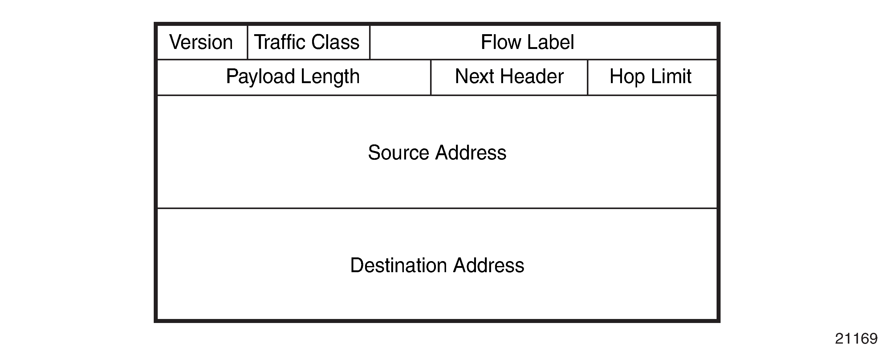
IPv6 Headers
The IPv6 header format is shown in IPv6 Header Format. IPv6 Header Field Descriptions describes the fields.
Field |
Description |
|---|---|
Version |
4-bit IP version number (v6) |
Traffic Class |
8-bit value that enables a source to identify the delivery classification of its packets |
Flow Label |
20-bit flow label that can be used by a source to label packets for which the source requests special handling by IPv6 routers; for example, non-default QoS or real-time service A flow contains a series of packets that travel between a particular source and particular destination |
Payload Length |
The length of the payload (16-bit unsigned integer), which is the rest of the packet following the IPv6 header, in octets Any extension headers that are present in the packet are considered to be part of the payload; therefore, the payload always begins immediately after the Destination Address |
Next Header |
8-bit selector that identifies the type of header immediately following the IPv6 header. The Next Header uses the same values as the IPv4 protocol field for some protocols; for example, the values for TCP and UDP are the same for both IPv4 and IPv6. The Next Header values differ from IPv4 when IPv6 extension headers are identified or when IPv6 unique protocols, such as ICMPv6, are identified. |
Hop Limit |
8-bit unsigned integer that is decremented by 1 by each node that forwards the packet. If the hop limit is decremented to 0, the packet is discarded and the node sends the ICMPv6 message ‟Hop Limit Exceeded in transit” back to the sender. |
Source Address |
128-bit address of the originator of the packet |
Destination Address |
128-bit address of the intended recipient of the packet |
Neighbor Discovery
IPv6 provides autoconfiguration of addresses, where equipment connecting to an IPv6 network can autoconfigure a usable address. There are two types of address autoconfiguration: stateless and stateful. Stateless autoconfiguration requires no manual configuration of hosts, minimal configuration of routers, and no servers. The host generates its own addresses using locally available information and information advertised by routers, such as the 7705 SAR. Stateless autoconfiguration is a feature of the neighbor discovery protocol.
Stateful autoconfiguration involves hosts obtaining interface addresses and/or configuration information from a server. For more information about stateful configuration, see DHCP Relay and DHCPv6 Relay.
Stateless autoconfiguration uses two neighbor discovery messages: router solicitation and router advertisement. The host sends router solicitation messages to find routers, and the routers send router advertisement messages to indicate their presence. The host sends the router solicitation message to all routers, requesting the IPv6 prefix as well as the IPv6 address of the routers. Each router responds with a router advertisement message indicating their IPv6 prefix and IPv6 address.
Neighbor discovery performs Layer 2 neighbor address resolution similar to ARP in IPv4. In addition, the neighbor discovery protocol performs a neighbor reachability function, where a ‟stale” neighbor entry is probed for reachability using a unicast neighbor solicitation message. This function ensures that link-layer address changes will be discovered reliably in addition to confirming the presence of the IPv6 neighbor.
Neighbor discovery is implemented within ICMPv6.
IPv6 Provider Edge over MPLS (6PE)
6PE allows IPv6 domains to communicate with each other over an IPv4 MPLS core network. Because forwarding is based on MPLS labels, backbone infrastructure upgrades and core router reconfiguration is not required in this architecture. 6PE is a cost-effective solution for IPv6 deployment.
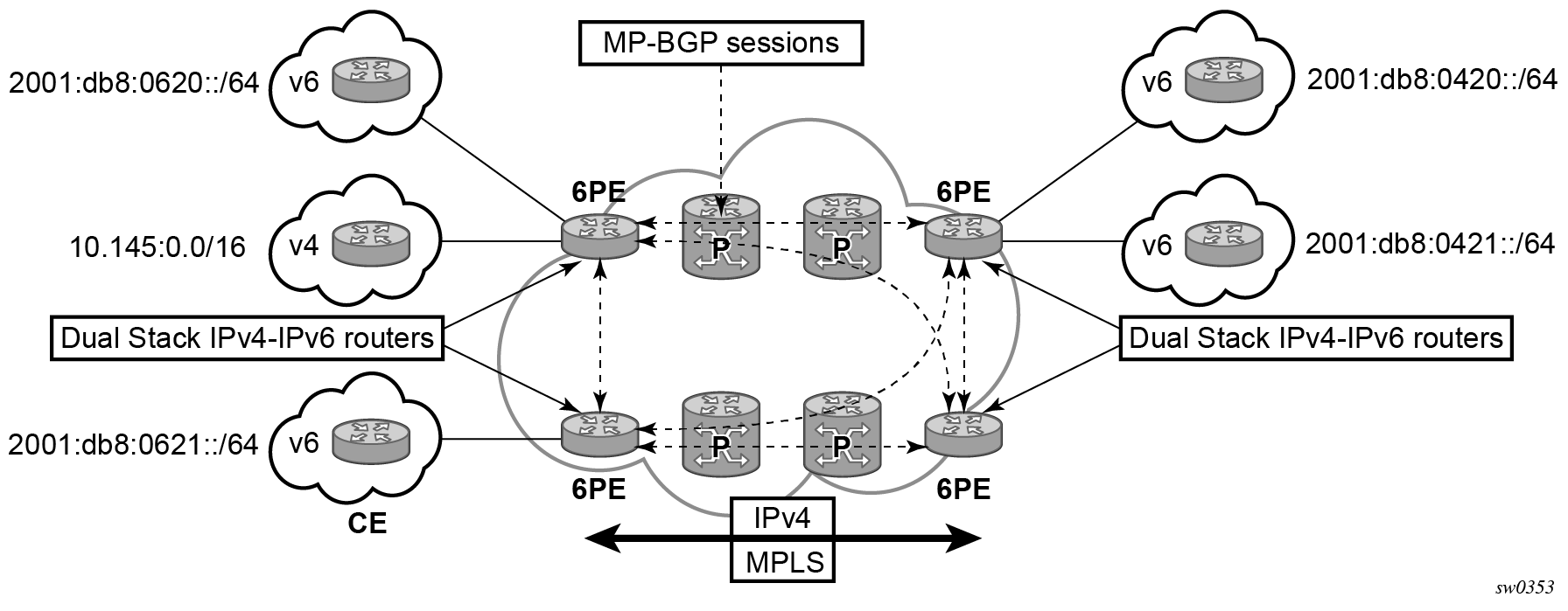
6PE Control Plane Support
The 6PE MP-BGP routers support:
- IPv4 and IPv6 dual-stack
- MP-BGP to exchange IPv6 reachability information:
- The 6PE routers exchange IPv6 reachability information using MP-BGP (AFI 2, SAFI 4).
- An IPv4 address of the 6PE router is encoded as an IPv4-mapped IPv6 address in the BGP next-hop field. This is usually the IPv4 system address.
-
The 6PE router binds MPLS labels to the IPv6 prefixes it advertises. The 7705 SAR routers only advertise the
IPv6 explicit null (value 2) in advertised 6PE routes.
- The most preferred tunnel to the BGP next hop allowed by the 6PE resolution filter is used to tunnel the traffic to the remote 6PE router; the preferred tunnels are configured using the resolution-filter command under the config>router>bgp>next-hop-resolution>label-route-transport-tunnel>family context.
6PE Data Plane Support
The ingress 6PE router can push two or more MPLS labels to send the packets to the egress 6PE router. The top labels are associated with resolving the transport tunnels. The bottom label is advertised in MP-BGP by the remote 6PE router. Only the IPv6 explicit null (value 2) label is used.
The egress 6PE router pops the top transport labels. When the IPv6 explicit null label is exposed, the egress 6PE router knows that an IPv6 packet is encapsulated. It pops the IPv6 explicit null label and performs an IPv6 route lookup to find the next hop for the IPv6 packet.
Router ID
The router ID is a 32-bit IP address (IPv4) that uniquely identifies the router within an autonomous system (see Autonomous Systems).
IS-IS and BGP use the router ID as their system ID.
OSPF routers use the router IDs of the neighbor routers to establish adjacencies. Neighbor IDs are learned when Hello packets are received from the neighbor.
Before configuring OSPF parameters, ensure that the router ID is derived by one of the following methods:
define the value using the config>router>router-id ip-address command
define the system interface using the config>router>interface ip-int-name command (used if the router ID is not specified with the config>router>router-id ip-address command), or, if the 7705 SAR is acting as a DHCP client, allow the system interface to be defined dynamically by configuring the DHCP server-facing interface as unnumbered.
A system interface (also referred to as the loopback address) must have an IP address with a 32-bit subnet mask. The system interface is assigned during the primary router configuration process when the interface is created in the logical IP interface context.
if you do not specify a router ID, the last 4 bytes of the MAC address are used
the router ID can be derived on the protocol level; for example, BGP
Autonomous Systems
Networks can be grouped into areas. An area is a collection of network segments within an autonomous system (AS) that have been administratively assigned to the same group. An area’s topology is concealed from the rest of the AS, which results in a significant reduction in routing traffic.
Routing in the AS takes place on two levels, depending on whether the source and destination of a packet reside in the same area (intra-area routing) or different areas (inter-area routing). In intra-area routing, the packet is routed solely on information obtained within the area; no routing information obtained from outside the area can be used. This protects intra-area routing from the injection of bad routing information.
Routers that belong to more than one area are called area border routers. All routers in an AS do not have an identical topological database. An area border router has a separate topological database for each area it is connected to. Two routers, which are not area border routers, belonging to the same area, have identical area topological databases.
Autonomous systems share routing information, such as routes to each destination and information about the route or AS path, with other ASs using BGP. Routing tables contain lists of next hops, reachable addresses, and associated path cost metrics to each router. BGP uses the information and path attributes to compile a network topology.
DHCP and DHCPv6
DHCP is a configuration protocol used to communicate network information and configuration parameters from a DHCP server to a DHCP-aware client. DHCP is based on the BOOTP protocol, with additional configuration options and the added capability of allocating dynamic network addresses. DHCP-capable devices are also capable of handling BOOTP messages.
A DHCP client is an IP-capable device (typically a computer or base station) that uses DHCP to obtain configuration parameters such as a network address. A DHCP server is an Internet host or router that returns configuration parameters to DHCP clients. A DHCP/BOOTP Relay agent is a host or router that passes DHCP messages between clients and servers.
DHCPv6 is not based on, and does not use, the BOOTP protocol.
Home computers in a residential high-speed Internet application typically use the DHCP protocol to have their IP address assigned by their Internet service provider.
The 7705 SAR can act as a DHCP client, a DHCP or DHCPv6 Relay agent, or a local DHCP or DHCPv6 server.
When used as a CPE device, the 7705 SAR can act as a DHCP client to learn the IP address of the network interface. Dynamic IP address allocation is supported on both network and system interfaces.
OSPF, IS-IS, or RIP is used to advertise the system IP address over the network interface to the next-hop router. Static routing cannot be used because the network interface IP address is dynamic and can change during normal operation.
For DHCP, the DHCP protocol requires the client to transmit a request packet with a destination broadcast address of 255.255.255.255 that is processed by the DHCP server.
For DHCPv6, the DHCP protocol requires the client to transmit a request packet with a destination multicast address of ff02::1:2 (all DHCP servers and relay agents on the local network segment) that is processed by the DHCP server.
Since IP routers do not forward broadcast or multicast packets, this would suggest that the DHCP client and server must reside on the same network segment. However, for various reasons, it is sometimes impractical to have the server and client reside in the same IP network.
When the 7705 SAR is acting as a DHCP Relay agent, it processes these DHCP broadcast or multicast packets and relays them to a preconfigured DHCP server. Therefore, DHCP clients and servers do not need to reside on the same network segment.
When the 7705 SAR is acting as a local DHCP server, it processes these DHCP broadcast or multicast packets and allocates IP addresses for the DHCP client as needed.
The 7705 SAR supports a maximum of 16 servers per node on the 7705 SAR-A, 7705 SAR-Ax, 7705 SAR-H, 7705 SAR-Hc, 7705 SAR-M, 7705 SAR-Wx, and 7705 SAR-X. The 7705 SAR supports a maximum of 62 servers per node on the 7705 SAR-8 Shelf V2 and on the 7705 SAR-18. Any Layer 3 interface configured using the global routing table or Layer 3 services supports up to 8 servers.
DHCP Relay and DHCPv6 Relay
The 7705 SAR provides DHCP/BOOTP Relay agent services and DHCPv6 Relay agent services for DHCP clients. DHCP is used for IPv4 network addresses and DHCPv6 is used for IPv6 network addresses. Both DHCP and DHCPv6 are known as stateful protocols because they use dedicated servers to maintain parameter information.
In the stateful autoconfiguration model, hosts obtain interface addresses and/or configuration information and parameters from a server. The server maintains a database that keeps track of which addresses have been assigned to which hosts.
The 7705 SAR supports DHCP Relay on the base router, and on access IP interfaces associated with IES and VPRN. Each DHCP instance supports up to 8 DHCP servers.
The 7705 SAR supports DHCPv6 Relay on access IP interfaces associated with IES and VPRN. Each DHCPv6 instance supports up to 8 DHCPv6 servers. For more information about DHCPv6 Relay, see the 7705 SAR Services Guide, ‟DHCPv6 Relay”.
DHCP Relay Agent Options
DHCP options are codes that the 7705 SAR inserts in packets being forwarded from a DHCP client to a DHCP server. Some options have additional information stored in suboptions.
The 7705 SAR supports Option 60 and Option 61 as specified in RFC 2132. Option 60 is the vendor class identifier, which can contain information such as the client’s hardware configuration. Option 61 is the client identifier.
The 7705 SAR supports the Relay Agent Information Option 82 as specified in RFC 3046. The following suboptions are supported for the base router:
action
circuit ID
copy-82
remote ID
Local DHCP and DHCPv6 Server
The 7705 SAR supports local DHCP server functionality on the base router and on access IP interfaces associated with VPRN, by dynamically assigning IPv4 or IPv6 addresses to access devices that request them. This standards-based, full DHCP server implementation allows a service provider the option to decentralize IP address management into the network. The 7705 SAR can support public and private addressing in the same router, including overlapped private addressing in the form of VPRNs in the same router.
The 7705 SAR acts as a DHCP server or a DHCPv6 server.
An administrator creates pools of addresses that are available for assigned hosts. Locally attached hosts can obtain an address directly from the server. Routed hosts receive addresses through a relay point in the customer’s network.
When a DHCP server receives a DHCP message from a DHCP Relay agent, the server looks for a subnet to use for assigning an IP address. If configured with the use-pool-from-client command, the server searches Option 82 information for a pool name. If a pool name is found, an available address from any subnet of the pool is offered to the client. If configured with the use-gi-address command, the server uses the gateway IP address (GIADDR) supplied by the Relay agent to find a matching subnet. If a subnet is found, an address from the subnet is offered to the client. If no pool or subnet is found, then no IP address is offered to the client.
When a DHCPv6 server receives a DHCP message from a DHCPv6 Relay agent, the server looks for a subnet to use for assigning an IP address. If configured with the use-pool-from-client command, the server searches Option 17 information for a pool name. If a pool name is found, an available address from any subnet of the pool is offered to the client. If configured with the use-link-address command, the server uses the address supplied by the Relay agent to find a matching subnet prefix. If a prefix is found, an address from the subnet is offered to the client. If no pool or prefix is found, then no IP address is offered to the client.
IPv4 and IPv6 address assignments are temporary and expire when the configured lease time is up. The server can reassign addresses after the lease expires.
If both the no use-pool-from-client command and the no use-gi-address command or no use-link-address command are specified, the server does not act.
DHCP and DHCPv6 Server Options
Options and identification strings can be configured on several levels.
DHCP servers support the following options, as defined in RFC 2132:
Option 1—Subnet Mask
Option 3—Default Routers
Option 6—DNS Name Servers
Option 12—Host Name
Option 15—Domain Name
Option 44—Netbios Name Server
Option 46—Netbios Node Type Option
Option 50—IP Address
Option 51—IP Address Lease Time
Option 53—DHCP Message Type
Option 54—DHCP Server IP Address
Option 55—Parameter Request List
Option 58—Renew (T1) Timer
Option 59—Renew (T2) Timer
Option 60—Class Identifier
Option 61—Client Identifier
DHCP servers also support Suboption 13 Relay Agent Information Option 82 as specified in RFC 3046, to enable the use of a pool indicated by the DHCP client.
DHCPv6 servers support the following options, as defined in RFC 3315:
Option 1—OPTION_CLIENTID
Option 2—OPTION_SERVERID
Option 3—OPTION_IA_NA
Option 4—OPTION_IA_TA
Option 5—OPTION_IAADDR
Option 6—OPTION_ORO
Option 7—OPTION_PREFERENCE
Option 8—OPTION_ELAPSED_TIME
Option 9—OPTION_RELAY_MSG
Option 11—OPTION_AUTH
Option 12—OPTION_UNICAST
Option 13—OPTION_STATUS_CODE
Option 14—OPTION_RAPID_COMMIT
Option 15—OPTION_USER_CLASS
Option 16—OPTION_VENDOR_CLASS
Option 17—OPTION_VENDOR_OPTS
Option 18—OPTION_INTERFACE_ID
Option 19—OPTION_RECONF_MSG
Option 20—OPTION_RECONF_ACCEPT
These options are copied into the DHCP reply message, but if the same option is defined several times, the following order of priority is used:
subnet options
pool options
options from the DHCP client request
A local DHCP server must be bound to a specified interface by referencing the server from that interface. The DHCP server will then be addressable by the IP address of that interface. A normal interface or a loopback interface can be used.
A DHCP client is defined by the MAC address and the circuit identifier. This implies that for a certain combination of MAC and circuit identifier, only one IP address can be returned; if more than one request is made, the same address will be returned.
ICMP and ICMPv6
Internet Control Message Protocol (ICMP) is part of the Internet Protocol Suite as defined in RFC 792, Internet Control Message Protocol, for IPv4 and RFC 4443, Internet Control Message Protocol (ICMPv6) for the Internet Protocol Version 6 (IPv6) Specification. The neighbor discovery capability of ICMPv6 is specified in RFC 4861, Neighbor Discovery for IP Version 6 (IPv6).
ICMP messages are typically generated in response to errors in IP datagrams or for diagnostic or routing purposes. The ICMP ping utility for IPv4 and IPv6 and the ICMP traceroute utility for IPv4 are described in the 7705 SAR OAM and Diagnostics Guide, ‟ICMP Diagnostics”.
The 7705 SAR supports the ICMP capabilities described in ICMP Capabilities for IPv4 .
ICMP Message |
Description |
|---|---|
Address mask reply |
Used to reply to an address mask request with an appropriate subnet mask |
Time exceeded (TTL expired) |
Generated by a router to inform the source of a packet that was discarded due to the time to live (TTL) field reaching zero Used by the traceroute utility to obtain a list of hosts that the packets traversed from source to destination |
Destination unreachable |
Generated by a router to inform the source host that the destination is unreachable for a specified reason |
Echo request/Echo reply |
Used by the ping utility to test whether a host is reachable across an IP network and to measure the round-trip time for packets sent from the local host to a destination node |
The 7705 SAR supports the ICMPv6 capabilities described in ICMPv6 Capabilities for IPv6 .
ICMPv6 Message |
Description |
|---|---|
Destination unreachable |
Generated by a router to inform the source host that the destination is unreachable for a specified reason, other than congestion |
Packet too big |
Generated by a router in response to a packet that it cannot forward because the packet is larger than the MTU of the outgoing link. |
Time exceeded |
Generated by a router to inform the source of a packet that was discarded because the hop limit was exceeded in transit |
Parameter problem |
Generated by a router to inform the source of a packet that the packet was discarded due to a problem with a field in the IPv6 header or extension header that prevented it from processing the packet |
Echo request/Echo reply |
Used by the ping utility to test whether a host is reachable across an IP network and to measure the round-trip time for packets sent from the local host to a destination node |
Neighbor Discovery ICMPv6 Messages |
|
Router solicitation |
Sent by a host, when an interface is enabled, to request routers to generate router advertisements immediately rather than at their next scheduled time |
Router advertisement |
Sent by a router to advertise its presence as well as link and Internet parameters, periodically or in response to a router solicitation message |
Neighbor solicitation |
Sent by a node to determine the link-layer address of a neighbor or to verify that a neighbor is still reachable |
Neighbor advertisement |
Sent by a node in response to a neighbor solicitation message Nodes can also send unsolicited neighbor advertisements to announce a link-layer address change |
Static Routes, Dynamic Routes, and ECMP
Static routes to next-hop addresses are supported on the 7705 SAR. Dynamic routing using the OSPF, RIP, IS-IS, or BGP protocols is also supported.
If the 7705 SAR chassis is equipped with two Control and Switching modules (CSMs) for redundancy, non-stop services are supported. Therefore, if the active CSM experiences an activity switch, all static route entries are maintained.
Equal-Cost Multipath Protocol (ECMP) refers to the distribution of packets over two or more egress links that share the same routing cost. ECMP is supported on static routes and dynamic (OSPF, IS-IS, and BGP) routes. The 7705 SAR supports ECMP for both LDP and IP traffic.
ECMP for LDP can be used to distribute MPLS traffic across the links in order to balance the traffic load. ECMP for LDP load-balances traffic across all equal-cost links based on the output of the hashing algorithm using the allowed inputs, based on the service type. For detailed information, refer to the 7705 SAR Interface Configuration Guide, ‟LAG and ECMP Hashing”. Refer also to the 7705 SAR MPLS Guide, ‟ECMP Support for LDP”, for more information.
For IP-routed traffic, as shown in Table 15 in the 7705 SAR Interface Configuration Guide, ‟LAG and ECMP Hashing”, the 7705 SAR load-balances the traffic over multiple equal-cost links with a hashing algorithm that uses header fields from incoming packets to calculate which link to use. By adding additional fields to the algorithm, the randomness of the results can be increased to ensure a more even distribution of packets across available links. ECMP for IP allows load balancing to be configured across all IP interfaces at the system level or interface level on the network side. Configuration at the interface level overrides the system-level settings for the specific interface. IP ECMP is supported on all 7705 SAR adapter cards and platforms.
Interfaces on the system can have any mixture of load-balancing configurations, including having load balancing disabled. Router updates often cause interface load- balancing configuration changes. The 7705 SAR will automatically continue processing packets using the new interface configuration.
ECMP is configured on the interface but is agnostic to the underlying SAP, spoke SDP, or VPLS binding. ECMP configuration is maintained even if the binding type changes.
If multiple routes are learned with an identical preference using the same protocol, the lowest-cost route is used. If multiple routes are learned with an identical preference using the same protocol and the costs (metrics) are equal, the decision of which route to use is determined by the configuration of ECMP.
Preferences are set on static routes in the config>router>static-route-entry context. Preferences are set on OSPF routes in the config>router>ospf context, on RIP routes in the config>router>rip context, on IS-IS routes in the config>router>isis>level context, and on BGP routes in the config>router>bgp context (see the 7705 SAR Routing Protocols Guide for OSPF, IS-IS, and BGP configuration).
Static Route Resolution Using Tunnels
Static route packets can be forwarded to an indirect next hop over a tunnel programmed in the TTM using the config>router>static-route-entry>tunnel-next-hop command.
If the tunnel-next-hop context is enabled and the resolution command under this context is set to any, any supported tunnel type in the static route context can be selected following the TTM preference. If resolution is set to disabled, the tunnel binding is removed and resolution to the next hop resumes in the RTM. If resolution is set to filter, the route can be bound to a subset of active tunnels in the TTM, determined by the resolution-filter configuration in the tunnel-next-hop context.
The following tunnel types are supported in the static route context: LDP, RSVP-TE, SR-ISIS, SR-OSPF, and SR-TE.
See Router Global Commands for more information about the tunnel-next-hop command.
Enabling ECMP
The ECMP decision is performed at the ingress point on the node; therefore, ECMP must always be enabled on the ingress interface.
To enable LDP and GRT IP ECMP, the config>router>ecmp command is used.
To enable IP ECMP on a per-IP, next-hop basis (far-end PE) under the IP-VPRN context, the config>service>vprn>ecmp command is used.
For LDP ECMP, the lsr-load-balancing command under the system context enables optional LSR load balancing for the node. The lsr-load-balancing command under the router interface context overrides the system configuration for the specified interface.
For IP ECMP, the l4-load-balancing command under the system context enables optional Layer 4 load balancing for the node. The l4-load-balancing command under the router interface context, IES service interface context, or VPRN service interface context overrides the system configuration for the specified interface.
For IP ECMP, the teid-load-balancing command can be configured under the router interface context, IES interface context, and VPRN interface context.
For both LDP and IP ECMP, the system-ip-load-balancing command can be configured under the system context.
For information about the load-balancing commands, see Router Interface Commands, the 7705 SAR Basic System Configuration Guide, ‟System Information and General Commands”, and the 7705 SAR Services Guide, ‟VLL Services Command Reference”, ‟VPLS Command Reference”, ‟IES Command Reference”, and ‟VPRN Services Command Reference”.
IGP-LDP and Static Route-LDP Synchronization
With LDP, FECs learned from an interface do not necessarily link to that interface state. As long as the router that advertised the labels is reachable, the learned labels are stored in the incoming label map (ILM) table.
Although this feature gives LDP a lot of flexibility, it can also cause problems. For example, when an interface comes back up from a failure or from a shutdown state, the static routes bound to that interface are installed immediately. However, the LDP adjacency to the next hop may not be up, which means that the LDP SDP remains down. In this case, the MPLS traffic will be blackholed until the LDP adjacency comes up.
The same issue is also applicable to dynamic routes (OSPF and IS-IS).
To resolve this issue, the LDP synchronization timer enables synchronization of IGP or static routes to the LDP state.
With IGP, when a link is restored after a failure, IGP sets the link cost to infinity and advertises it. The value advertised in OSPF is 0xFFFF (65535). The value advertised in IS-IS regular metric is 0x3F (63) and in IS-IS wide-metric is 0xFFFFFE (16777214).
After IGP advertises the link cost, the LDP hello adjacency is brought up with the neighbor. The LDP synchronization timer is started by IGP from the time the LDP session to the neighbor is up over the interface. This synchronization timer allows time for the label-FEC bindings to be exchanged.
When the LDP synchronization timer expires, the link cost is restored and is readvertised. IGP will announce a new best next-hop and LDP will use it if the label binding for the neighbor’s FEC is available.
The above behavior is similar for static routes. If the static route is enabled for ldp-sync, the route is not enabled immediately after the interface to the next hop comes up. Routes are suppressed until the LDP adjacency with the neighbor comes up and the synchronization timer expires. The timer does not start until the LDP adjacency with the neighbor node is fully established. For static routes, the ldp-sync-timer function requires LDP to use the interface address, not the system address, as its transport address.
Bidirectional Forwarding Detection (BFD)
BFD is a simple protocol for detecting failures in a network. BFD uses a ‟hello” mechanism that sends control messages periodically to the far end and receives periodic control messages from the far end. BFD is implemented for IGP and BGP protocols, including static routes, in asynchronous mode only, meaning that neither end responds to control messages; rather, the messages are sent in the time period configured at each end.
Due to the lightweight nature of BFD, it can detect failures faster than other detection protocols, making it ideal for use in applications such as mobile transport.
If the configured number of consecutive BFD missed messages is reached, the route to the peer is declared not active. For centralized and line card BFD sessions, failure detection is propagated to all impacted upper layer protocols within a few milliseconds. Upper layer protocols act on failure information as soon as it is made available by BFD.
The v-port on the 2-port 10GigE (Ethernet) Adapter card and on the 2-port 10GigE (Ethernet) module is linked to the ring ports through the add/drop port, therefore its operational status—always operationally up—is not dependent on the status of the ring ports. Hence a ring port failure will not necessarily trigger an action at the v-port.
To ensure that there is fast detection of any Layer 2 failure and that protocols on the v-port will react to the failure, you must run health-check tests or OAM tests with the peer or peers at the far end. For example, BFD must be configured between the v-port and the far-end IP interface. The use of health-check tests to the far-end interface will trigger upper layer protection mechanisms on the v-port, where the behavior will be comparable to an intermediate Layer 2 transport network failure on any other Ethernet port.
For IPv4, BFD is supported on static routes, OSPF, IS-IS, BGP, PIM, RSVP-TE, L-LDP, and T-LDP. For IPv6, BFD is supported on static routes, IPv6 interfaces, L-LDP, T-LDP, and OSPFv3. The 7705 SAR also supports centralized BFD on Layer 3 spoke SDP interfaces. This capability allows BFD on Layer 3 spoke SDP interfaces to ride over the applicable tunnel and the configured spoke SDP to the far-end node where the spoke SDP is terminated. It offers a fast way to detect failures on Layer 3 interfaces riding over spoke SDPs; for example, service traffic running over an LSP tunnel.
For network topologies where the BGP and/or T-LDP peer IP address is not a direct next hop (that is, the peer IP address is not an interface IP address but is either a system IP address or loopback IP address, or is multiple hops away), BFD automatically uses a centralized session to keep track of far-end IP address availability.
Centralized next-hop BFD for static forwarding entries, or for OSPF or IS-IS routing protocols, is not supported on any loopback or system interface regardless of the configured mode (access or network) when the loopback interfaces have no physical associated ports. However, multi-hop centralized BFD sessions (for example, BGP, T-LDP) can make use of any loopback interface.
Seamless BFD
The 7705 SAR supports seamless BFD (S-BFD) as defined in RFC 7880. S-BFD is a form of BFD that avoids the negotiation and state establishment that is required for BFD sessions. The BFD session discriminator is predetermined and other mechanisms are used to distribute the discriminators to a remote network entity. This allows client applications or protocols to more quickly initiate and perform connectivity tests. Furthermore, a per-session state is maintained only at the head end of an S-BFD session. The tail end simply reflects BFD control packets back to the head end.
An S-BFD session is established between an initiator and a reflector. To participate in an S-BFD session, a mapping table of remote discriminators to far-end peer IP addresses must be statically configured on the 7705 SAR. The S-BFD initiator can begin sending BFD packets when it knows the reflector discriminator at the far-end node.
The 7705 SAR can be configured to act as a reflector. Only one reflector instance is supported per router and a discriminator is assigned to the reflector. Each of the initiators on the router is also assigned a discriminator.
Seamless BFD sessions are created at the request of a client application such as MPLS. This section describes the base S-BFD configuration that is required on initiator and reflector routers in order to participate in an S-BFD session. Application-specific configuration is required to create S-BFD sessions; for information, see the 7705 SAR MPLS Guide, ‟Seamless BFD for SR-TE LSPs”.
S-BFD Reflector Configuration and Behavior
The S-BFD reflector is configured using the following CLI commands:
configure
   bfd
      seamless-bfd
        [no] reflector <name>
                  description <string>
                  discriminator <value>
                  local-state {up | admin-down}
                  [no] shutdown
S-BFD reflection is enabled on the router when the S-BFD discriminator is configured. The discriminator value is configured from a defined range.
When the router receives an S-BFD packet from the initiator and the value in the YourDiscriminator field in the packet matches the configured discriminator value on the local router, the local router will send the S-BFD packet back to the initiator via a routed path. The State field in the reflected packet is populated with either the Up or AdminDown value based on the local-state configuration.
When the S-BFD reflector returns the S-BFD packet to the initiator, the source and destination UDP ports are swapped in the S-BFD response; that is, the received source port becomes the transmitted destination port and the received destination port becomes the transmitted source port.
S-BFD control packets are discarded when the reflector is not configured, or is shut down, or when the YourDiscriminator field does not match the discriminator of the reflector. Only IPv4 addresses are supported.
S-BFD Initiator Global Configuration
Before an application can request the establishment of an S-BFD session, a mapping table of remote discriminators to far-end peer IP addresses must exist on the router. This is statically configured using the following CLI commands:
configure>router>bfd
   seamless-bfd
      peer <ip-address> discriminator <remote-discriminator>
      peer <ip-address> discriminator <remote-discriminator>
      ...
      exit
With S-BFD, no session setup is required. The S-BFD initiator immediately begins sending S-BFD packets when it knows the far-end reflector discriminator. The initiator state goes from AdminDown to Up when it begins to send S-BFD packets.
The S-BFD initiator sends S-BFD packets to the reflector using the following fields:
Src IP — the local session IP address
Dst IP — the configured reflector IP address
MyDiscriminator — the locally assigned discriminator value
YourDiscriminator — the configured reflector discriminator value
When the initiator receives a valid response from the reflector with an Up state, the initiator declares the S-BFD session up. When the initiator receives a valid response from the reflector with an AdminDown state, the initiator declares the S-BFD session down and reduces the transmission interval but does not consider the session failed.
If the initiator fails to receive a certain number of responses as determined by the BFD multiplier in the BFD template for the session, the initiator declares the S-BFD session failed.
If any of the discriminators change, the session is taken down and the router attempts to start a new session with the new values.
If the reflector discriminator is changed at the far-end peer, the session fails. If the reflector discriminator is changed at the far-end peer and the mapping has not been updated locally before the system checks for a new reflector discriminator from the local mapping table, the session is bounced and brought up with the new values.
If any of the discriminators are deleted, the corresponding S-BFD sessions are deleted.
S-BFD Session Configuration
An application that requires an S-BFD session must provide sufficient information to BFD so that it can create a unique S-BFD session to a remote IP address associated with the application object, such as an LSP. The session type (S-BFD) is determined by the application. BFD checks that the BFD template parameters are appropriate for the requested session type. The only S-BFD session type that is supported is np.
An S-BFD session is configured using the following parameters in the config>router>bfd>bfd-template context:
multiplier
receive interval
transmission interval
type
An S-BFD session must also include the following parameters configured in the config>router>bfd>seamless-bfd context:
remote reflector IP address
remote reflector discriminator
IP Fast Reroute (FRR)
IP Fast Reroute (FRR) protects against link or node failures in an IP network by precalculating a backup route to use when the primary next hop is not available. Both routes are populated in the RTM.
Without FRR, when a link or node failure occurs in a routed network, there is a period of disruption to the delivery of traffic until the network reconverges. Packets may be dropped or looped during this time, which can last hundreds of milliseconds.
IP FRR uses a Loop-Free Alternate (LFA) backup next hop to forward in-transit IP packets as soon as the primary next-hop failure is detected and the backup is invoked. This means that a node resumes forwarding IP packets to a destination prefix without waiting for the routing convergence. Convergence times should be similar to RSVP-TE FRR, in the tens of milliseconds.
When any of the following occurs, the backup LFA is enabled:
an OSPF or IS-IS interface goes operationally down, due to either a physical failure or a local administrative shutdown
a BFD session to a next hop times out when BFD is enabled on the interface
See RFC 5286, Basic Specification for IP Fast Reroute: Loop-Free Alternates, for more information about LFAs.
IP FRR is supported on IPv4 and IPv6 OSPF and IS-IS prefixes and on VPN-IPv4 OSPF prefixes forwarded in the base router instance. IP FRR also provides an LFA backup next hop for the destination prefix of a GRE tunnel used in an SDP or in VPRN auto-bind.
ECMP vs FRR
If ECMP is enabled, which provides multiple primary next hops for a prefix, IP FRR is not used. That is, the LFA next hops are not populated in the RTM and the ECMP paths are used instead.
IGP Shortcuts (RSVP-TE Tunnels)
IGP shortcuts are an MPLS functionality where LSPs are treated like physical links within IGPs; that is, LSPs can be used for next-hop reachability. If an RSVP-TE LSP is used as a shortcut by OSPF or IS-IS, it is included in the SPF calculation as a point-to-point link for both primary and LFA next hops. It can also be advertised to neighbors so that the neighboring nodes can also use the links to reach a destination via the advertised next hop.
IGP shortcuts can be used to simplify remote LFA support and simplify the number of LSPs required in a ring topology.
When both IGP shortcuts and LFA are enabled under OSPF or IS-IS, and IP FRR is also enabled, the following applies:
a prefix that is resolved to a direct primary next hop can be backed up by a tunneled LFA next hop
a prefix that is resolved to a tunneled primary next hop will not have an LFA next hop; it relies on RSVP-TE FRR for protection
IP FRR Configuration
To configure IP FRR, LFA calculation by the SPF algorithm must first be enabled under the OSPF, OSPFv3, or IS-IS protocol level with the command:
config>router>ospf>loopfree-alternates
or
config>router>ospf3>loopfree-alternates
or
config>router>isis>loopfree-alternates
LFA can also be enabled on an OSPF or OSPFv3 instance within a VPRN service with the command:
config>service>vprn>ospf>loopfree-alternates
or
config>service>vprn>ospf3>loopfree-alternates
Next, IP FRR must be enabled to use the LFA next hop with the command config>router>ip-fast-reroute.
If IGP shortcuts are used, they must be enabled under the OSPF or IS-IS routing protocol. As well, they must be enabled under the MPLS LSP context, using the command config>router>mpls>lsp>igp-shortcut.
For information about LFA and IGP shortcut support for OSPF and IS-IS, see the 7705 SAR Routing Protocols Guide, ‟LDP and IP Fast Reroute for OSPF Prefixes” and ‟LDP and IP Fast Reroute for IS-IS Prefixes”.
The 7705 SAR supports both IP FRR and LDP FRR; for information about LDP FRR, see the 7705 SAR MPLS Guide, ‟LDP Fast Reroute (FRR)”.
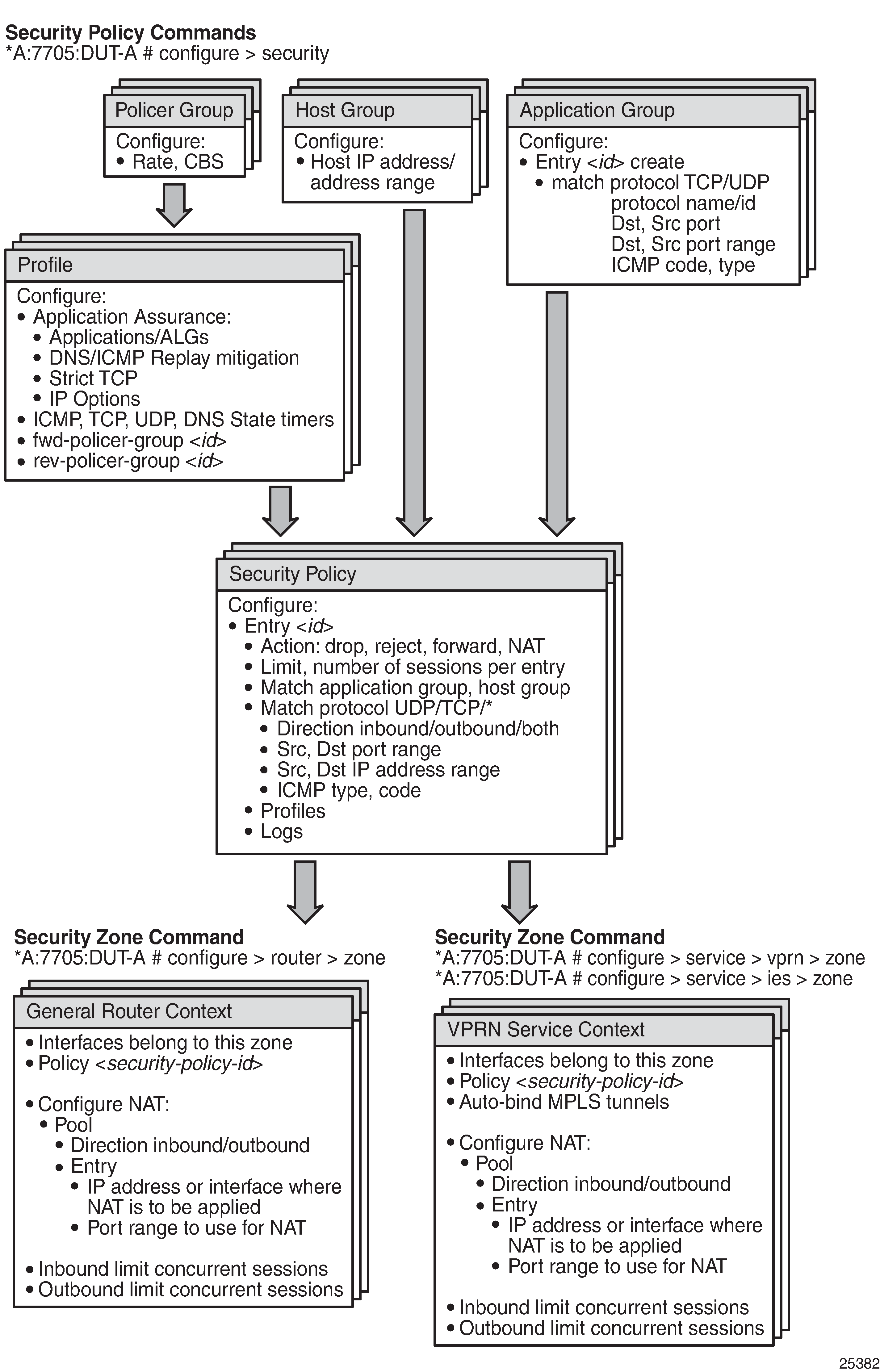
Configuring Security Parameters
The 7705 SAR supports a number of mechanisms for node security, including Access Control Lists (ACLs), Network Address Translation (NAT), and stateful, zone-based firewalls. For information about ACLs, see Configuring Filter Policies. For more details about NAT, see NAT Security.
Firewalls extend ACL filtering by ensuring that pass-through IP traffic between an inside (trusted private) network and an outside (untrusted public) network does not pose a security risk.
NAT and firewall security configurations are both based on zones. Zones segment a network, making it easier to control and organize traffic. A zone consists of a group of Layer 2 endpoints or Layer 3 interfaces with common criteria, bundled together. Security policies, which define a set of rules that determine how NAT or firewall should direct traffic, can be applied to the entire zone or to multiple zones. Layer 3 zones support both NAT and firewall security policies. Layer 2 zones support only firewalls. To enable NAT or firewall functionality, security policy and profile parameters must be configured under the config>security context in the CLI, and a security zone must be configured under one or more of the following contexts:
config>router>zone
config>service>epipe>zone
config>service>vpls>zone
config>service>vprn>zone
config>service>ies>zone
Layer 2 and Layer 3 firewalls share system resources; that is, they share the maximum number of policies, profiles, and session ID space supported by the system.
Firewall and NAT Security Configuration for the 7705 SAR shows the relationship between the configurable elements for firewall and NAT security.
This section describes the following topics:
Hardware Support
NAT and firewall security functionality is supported on the following cards and platforms:
on the 7705 SAR-8 Shelf V2 and the 7705 SAR-18:
2-port 10GigE (Ethernet) Adapter card
6-port Ethernet 10Gbps Adapter card
8-port Gigabit Ethernet Adapter card, version 3
10-port 1GigE/1-port 10GigE X-Adapter card, version 2 (7705 SAR-18 only)
Packet Microwave Adapter card
7705 SAR-Ax
7705 SAR-H
7705 SAR-Hc
7705 SAR-Wx
7705 SAR-X
Security Zone Configuration
NAT and firewall security configuration is based on zones. Zones segment a network, making it easier to control and organize traffic. A zone consists of a group of Layer 2 endpoints or Layer 3 interfaces with common criteria, bundled together. Security policies, which define a set of rules that determine how NAT or a firewall should direct traffic, can be applied to the entire zone or multiple zones.
A zone is created by adding at least one Layer 2 endpoint or Layer 3 interface to the zone configuration. Multiple zones can be created within each Layer 3 service or within the router context. Layer 2 services support only one zone. Layer 2 endpoints or Layer 3 interfaces from different services cannot be grouped into a single common zone. Security Zone Interfaces and Endpoints per Context lists the supported interfaces and endpoints that can be added to zones in each CLI context for NAT or firewall.
CLI Context |
Interface/Endpoint Type |
NAT |
Firewall |
|---|---|---|---|
Router |
Layer 3 |
✓ |
✓ |
Epipe |
SAP |
✓ |
|
Spoke-SDP termination |
✓ |
||
VPLS |
SAP |
✓ |
|
Spoke-SDP termination |
✓ |
||
Mesh SDP |
✓ |
||
EVPN |
|||
VPRN |
SAP |
✓ |
✓ |
Spoke-SDP termination |
✓ |
✓ |
|
IPSec private |
✓ |
✓ |
|
IPSec public |
✓ |
||
Routed VPLS |
✓ |
✓ |
|
IES |
SAP |
✓ |
✓ |
Spoke-SDP termination |
✓ |
✓ |
|
IPSec public |
✓ |
||
Routed VPLS |
✓ |
✓ |
A group of endpoints used for pseudowire redundancy cannot be added to a zone configured under an Epipe.
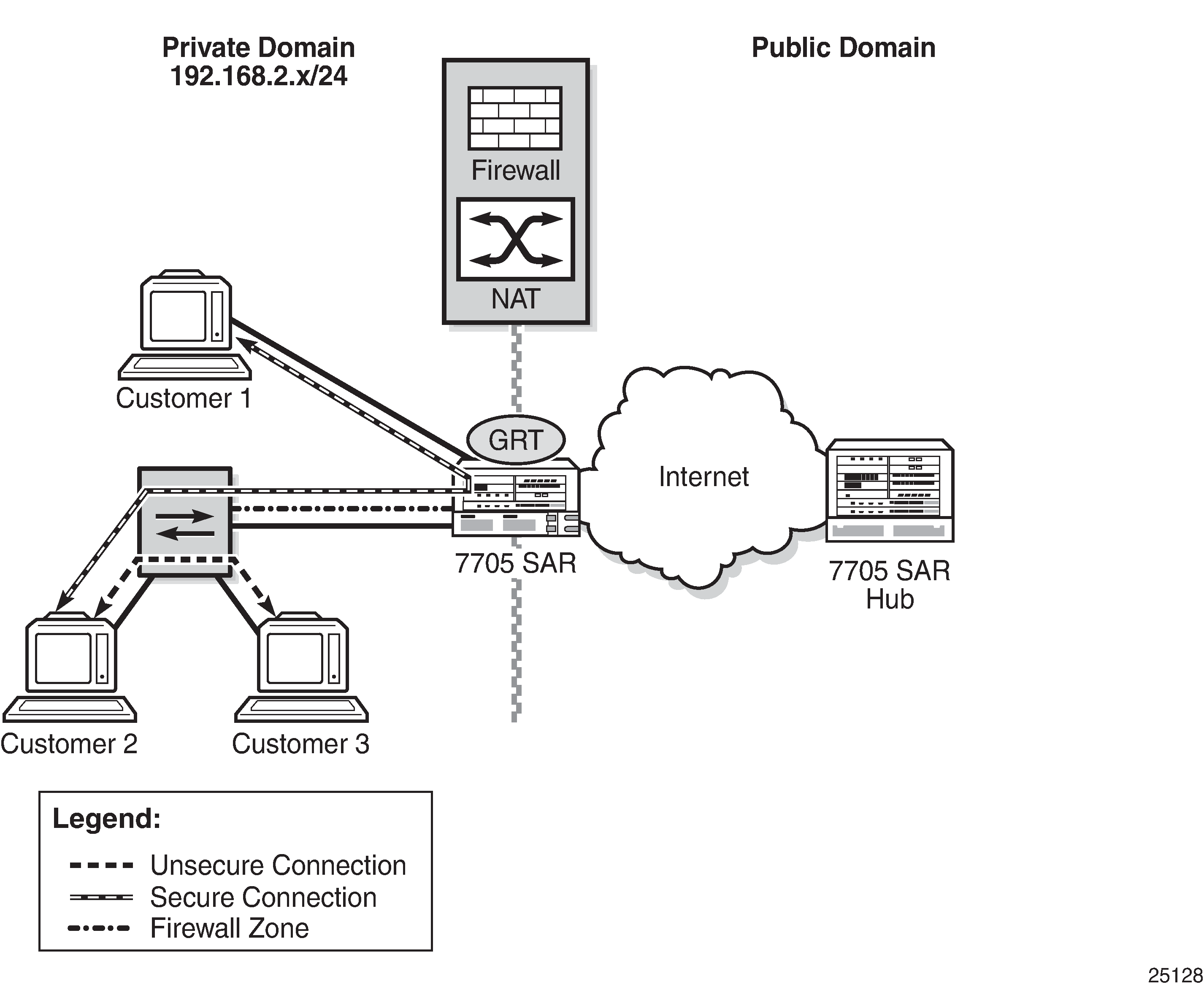
A zone configured within the router context is typically used to provide security functionality between an outside (insecure) network such as an ISP network or Layer 2/Layer 3 leased line network, and an inside (secure) network such as a corporate LAN or a small cell wireless network.
Firewall Protection of a Private Access Network shows a 7705 SAR connected to an insecure network (the public Internet), via the GRT. A firewall configured on the 7705 SAR protects the private access network from any connection that is not part of the 7705 SAR security policy.
For information about creating a security zone for VPRN, IES, VPLS, or Epipe services, see the applicable service chapters in the 7705 SAR Services Guide.
Security policies can be configured based on traffic entering (inbound) the zone, leaving (outbound) the zone, or both inbound and outbound traffic. A zone can be configured so that all traffic inbound to the zone has NAT and/or firewall applied to it based on the security policy configured for that zone. A zone can also be configured so that all traffic leaving the zone has NAT and/or firewall applied to it. And, a zone can be configured so that all traffic both inbound and outbound has firewall applied to it.
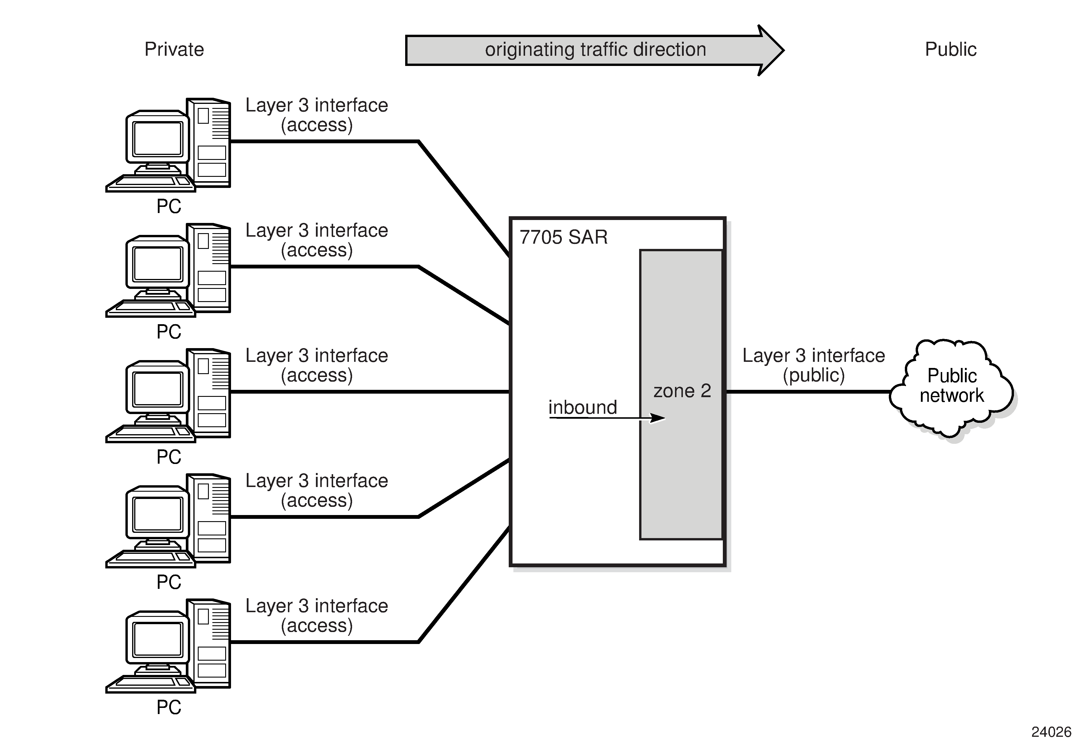
An example of inbound zone direction is shown in Zone Direction (Inbound). All traffic entering zone 2 has NAT applied to it based on the configured NAT policy assigned to zone 2.
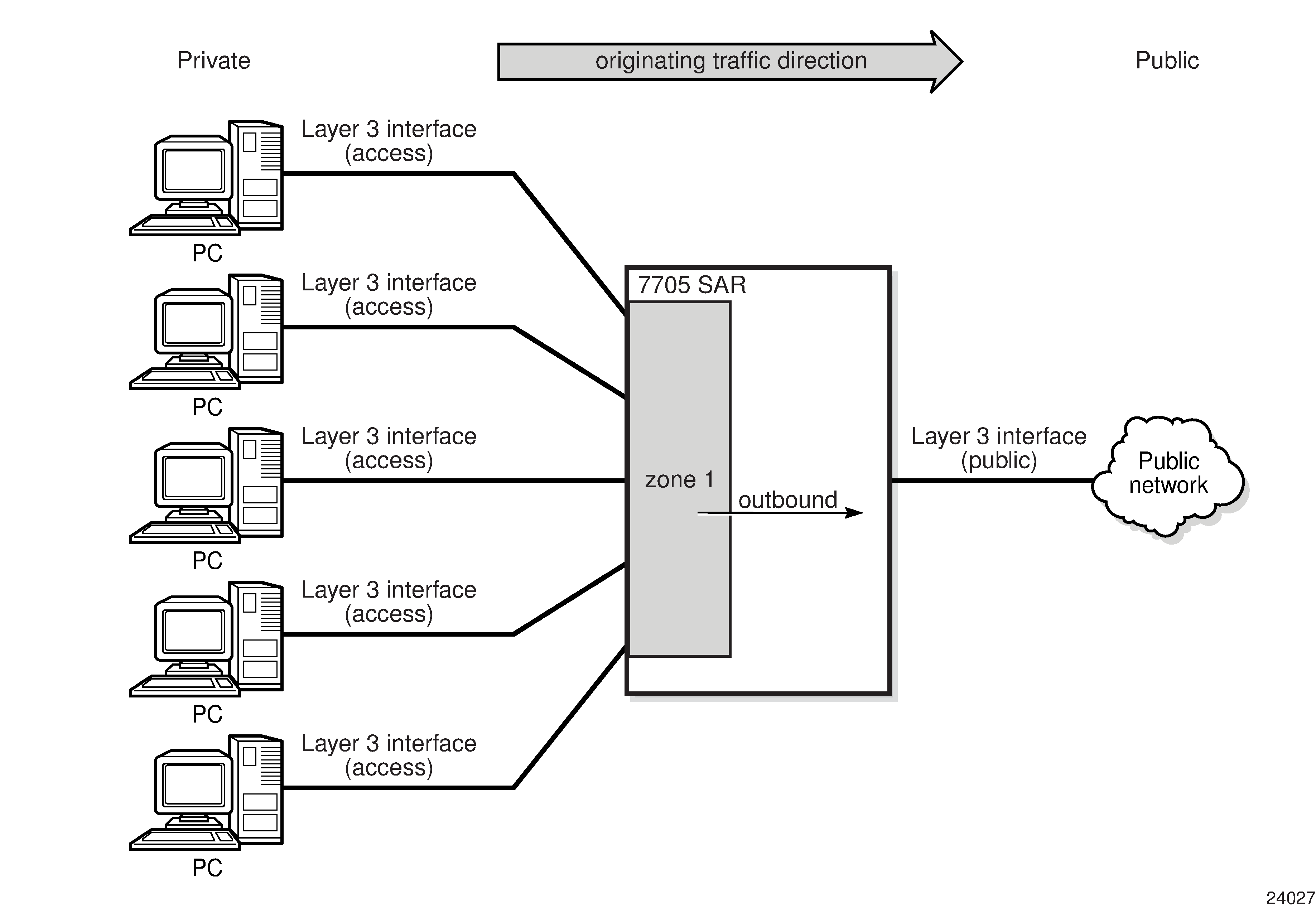
An example of outbound zone direction is shown in Zone Direction (Outbound). All traffic leaving zone 1 has NAT applied to it based on the configured NAT policy assigned to zone 1.
Security Session Creation
A firewall or NAT security session is established by extracting packets to the CSM and matching them against the rules configured in a security policy. Packet extraction is based on zone configuration. If a packet is inbound to or outbound from a security zone, the packet will be extracted to the CSM and examined by the firewall/NAT engine on the CSM.
If the extracted packet matches the criteria defined in the security policy, a connection session is set up using lookup criteria that are specific to the packet type and an accompanying action. For example, an IP packet uses a 6-tuple lookup of source IP address, destination IP address, source port, destination port, protocol, and VRF (where VRF 0 is the base routing table).
Depending on the match criteria and action, a copy of the session is downloaded to the datapath. For example, a session is not downloaded to the datapath if the action in the security policy is configured as reject. When the session is downloaded to the datapath, there is no further extraction to the CSM for examination; any subsequent packet matching the 6-tuple of the session occurs on the datapath session.
Some connection sessions are set up using more criteria in the lookup than 6-tuple while other sessions are set up using a 4-tuple lookup. Security Session Type and Session Tuple Signature lists the session type and session tuple signature.
Session Type |
Session Tuple Signature |
|---|---|
IP |
VRF, source IP address, destination IP address, and protocol |
UDP/TCP/SCTP |
VRF, source IP address, destination IP address, source port, destination port, and protocol |
ICMP |
VRF, source IP address, destination IP address, and ICMP request ID |
DNS |
VRF, source IP address, destination IP address, source port, destination port, protocol, and DNS transaction ID |
Some connection sessions require CSM extraction of every packet; for example, a connection that requires strict TCP. For this type of CSM connection, the TCP session state and sequence number must be examined for every packet on that connection. The connection session is downloaded to the datapath and marked for extra processing. The datapath then extracts every packet on this session to the firewall engine on the CSM. The throughput rate of these CSM firewall sessions is lower than that of datapath firewall sessions. Datapath sessions can process traffic at approximately the line rate. Any connection session that uses strict TCP is not hot-redundant and will time out after an activity switch.
Both CSM and datapath sessions are stateful as they can both read into TCP/UDP states and close the session based on the timers configured for that session.
On the 7705 SAR-8 Shelf V2 and 7705 SAR-18, security sessions survive a CSM redundancy switch; however, security sessions configured with strict TCP do not.
Zones can be configured to have session limits on a per-direction basis, in order to limit potential attacks.
Directionally Aware Security Behavior
A security session can be directionally aware. For example, a firewall security policy entry can be configured to allow packets with source IP address X and source port Y that are traveling from the private network to the public network to traverse the firewall. This means that any traffic arriving from the outside network on IP address X and port Y is denied entry to the inside network. However, a host in the private network can create a session from inside to outside for IP address X and port Y. Once this inside-to-outside session is created, traffic with IP address X and port Y traveling in the reverse direction (from outside to inside) is now allowed.
Similarly with NAT, a source NAT policy entry can be created to apply NAT on all arriving packets with source IP address X and source port Y to an outside source IP address A and source port B. When the first packet with IP address X and port Y arrives, NAT creates an inside-to-outside session and punches a hole through the firewall for that specific IP address and port number, thus allowing all packets to be transmitted from the inside network to the outside network.
TCP MSS Configuration and Adjustment
Typically, the MTU in a private LAN is larger than the MTU of a public network; the MTU of a private LAN is usually 1500 bytes whereas the MTU of a public network is usually less than 1500 bytes. In addition, packets destined for the public network may have an additional header, such as a transport tunnel, appended to the original packet. These two factors can cause the TCP/IP packet to become fragmented when entering the public network. Fragmentation is not desirable for TCP applications where the server needs a lot of processing power to reassemble the fragmented packets.
To avoid fragmentation, the maximum segment size (MSS) of application data in a TCP connection can be adjusted. Applications use the MSS to calculate the maximum number of data bytes (not including the header) that can be transmitted in a single packet. By lowering the MSS value, an outgoing packet's MTU can be made smaller than the public network MTU, ensuring that the packets entering the public network will not be fragmented.
The 7705 SAR supports TCP MSS adjustment. When acting as a CE router, the 7705 SAR can insert or modify the MSS value in the header of a TCP SYN or SYN-ACK packet. The sending and receiving CE routers set their MSS based on the outgoing interface MTU. The routers exchange TCP SYN or SYN-ACK packets during TCP session negotiation, engaging in a three-way handshake to compare and then select the lowest MSS value.
On the 7705 SAR, MSS configuration and adjustment is supported on the following cards and platforms:
on the 7705 SAR-8 Shelf V2 and the 7705 SAR-18:
2-port 10GigE (Ethernet) Adapter card
6-port Ethernet 10Gbps Adapter card
8-port Gigabit Ethernet Adapter card, version 3
10-port 1GigE/1-port 10GigE X-Adapter card, version 2 (7705 SAR-18 only)
Packet Microwave Adapter card
7705 SAR-Ax
7705 SAR-H
7705 SAR-Hc
7705 SAR-Wx
7705 SAR-X
When the tcp-mss command is configured, the 7705 SAR can adjust the MSS field in the TCP SYN packet or SYN-ACK packet. The 7705 SAR can also insert the MSS field in the TCP SYN packet and SYN-ACK packet if the field is not present.
The command is supported in the general router, VPRN service, and IES CLI contexts; MSS Configuration Interfaces per Context lists the supported interface types for each context.
The tcp-mss command is supported for TCP packets arriving on or leaving from MP-BGP tunnels in a VPRN only if tcp-mss is configured on VPRN SAP interfaces. Configuring tcp-mss only on the network interface that the MP-BGP traffic traverses will not cause the MSS adjustment to happen because labeled traffic can arrive on any network ingress interface, which may have different tcp-mss values configured.
CLI Context |
Interface Type |
|---|---|
Router |
Layer 3 |
|
VPRN |
SAP |
Spoke-SDP termination |
|
IPSec private |
|
r-VPLS |
|
|
IES |
SAP |
Spoke-SDP termination |
|
r-VPLS |
TCP MSS adjustment is supported on a Layer 3 IES or VPRN interface that is used as an r-VPLS interface for a Layer 2 VPLS or EVPN service. TCP MSS adjustment enables the 7705 SAR to modify or insert the MSS field in the TCP SYN and SYN-ACK packets traveling from a Layer 2 domain to a Layer 3 domain or traveling from a Layer 3 domain to a Layer 2 domain, via the r-VPLS interface that tcp-mss is configured on. The uplink supports GRE, MPLS, IPSec, NGE, or IP transport modes.
When the tcp-mss command is configured on an interface, TCP packets with a SYN or SYN-ACK flag will have the MSS value is adjusted or inserted as follows:
If the TCP session has no defined MSS, the 7705 SAR inserts the field in the TCP packet.
If the MSS value of the TCP session arriving from an access interface is greater than the MSS value configured on the 7705 SAR interface, the TCP session MSS is overwritten with the lower value.
If the MSS value of the TCP session arriving from an access interface is less than the MSS value configured on the 7705 SAR interface, the TCP session MSS does not change.
The command can be configured on an ingress interface, an egress interface, or both. When configured on both interfaces, the smallest MSS value is used.
Fragmented packets are not monitored for TCP MSS adjustment.
TCP MSS configuration and adjustment is supported for both IPv4 and IPv6 interfaces. Because the tcp-mss value is configured separately for each interface, it is possible to configure and enforce a different MSS value for IPv4 and IPv6.
Application Groups
An application group is a grouping of common criteria, such as the TCP/UDP port or ICMP code/type, used for a specific application. An application group is assigned to a security policy and application group criteria are matched in the policy. For further security, an application group can be configured with security profile parameters such as timeouts, fragmentation rules, and application assurance rules. Configuring an application group simplifies the configuration and management of firewall policies. An application group can be configured on the NSP NFM-P and downloaded to all routers at a particular network layer (either access or core) that require the same matching criteria.
Host Groups
A host group is a grouping of host IP addresses that can be added to a security policy. Configuring a host group simplifies the configuration of a security policy. Typically, service providers have a preassigned set of IP addresses that are allowed in the network. By creating a host group, a range of IP addresses or a single source/destination IP address is configured once and assigned to every edge router. The host group is added to the security policy as matching criteria.
Security Policy Policing
A private network can be infiltrated when an open port through the firewall is scanned and a DoS attack is initiated. The attack can use large amounts of bandwidth, starving existing connections of bandwidth and preventing other connections traversing through the firewall from using any bandwidth. To address this, a policer group can be configured against a profile and assigned to an entry within a security policy. All connections set up against that particular entry on the same adapter card or port are subjected to a policer rate and CBS buffer size. If the aggregate for one or more sessions using the policer group is exceeded, packets received beyond the policed rate are dropped and a log event is issued.
Security Profiles
Security profiles define security characteristics on the router, such as timers for different states of a TCP/UDP connection, application assurance parameter definitions, and whether to allow fragmented packets in a network. Security profiles can vary from subscriber to subscriber and are assigned to security policies, which are then applied to zones at the time the zone is created.
Profile Timers
Timers are used to time out a NAT or firewall session and drop it. The 7705 SAR supports configurable timers for different connections. Timers can be idle or strict. Idle timers are activated by the lack of traffic. Strict timers are used for protocol state changes and are not affected by the presence of traffic. The supported timers are described in Security Profile Timers.
Timer |
Description |
Timer Type |
CLI Command |
|---|---|---|---|
ICMP request |
Specifies the timeout for an ICMP session Default timeout: 1 min Minimum timeout: 1 min Maximum timeout: 5 min |
Strict |
icmp-request |
Idle timeout |
Specifies the timeout for a security session for IP packets that are not ICMP, TCP, or UDP Default timeout: 600 s Minimum timeout: 1 s Maximum timeout: 10800 s |
Idle |
other-sessions |
TCP established |
Specifies the timeout for a TCP session in the established state Default timeout: 2 h, 4 min Minimum timeout: 1 min Maximum timeout: 24 h |
Idle |
tcp-established |
TCP SYN |
Specifies the timeout applied to a TCP session in the SYN state Default timeout: 15 s Minimum timeout: 6 s Maximum timeout: 24 h |
Strict |
tcp-syn |
TCP time wait |
Specifies the timeout applied to a TCP session in a time-wait state Default timeout: n/a Minimum timeout: n/a Maximum timeout: 4 min |
Strict |
tcp-time-wait |
TCP transitory |
Specifies the idle timeout applied to a TCP session in a transitory state Default timeout: 4 min Minimum timeout: 1 min Maximum timeout: 24 h |
Strict |
tcp-transitory |
UDP |
Specifies the UDP mapping timeout Default timeout: 5 min Minimum timeout: 1 min Maximum timeout: 24 h |
Idle |
udp |
UDP DNS |
Specifies the timeout applied to a UDP session with destination port 53 Default timeout: 15 s Minimum timeout: 15 s Maximum timeout: 24 h |
Idle |
udp-dns |
UDP initial |
Specifies the timeout applied to a UDP session in its initial state Default timeout: 15 s Minimum timeout: 10 s Maximum timeout: 5 min |
Strict |
udp-initial |
Application Assurance Parameters
The following application assurance parameters can be defined in a security profile:
DNS
ICMP
IP options
strict TCP
DNS
Each DNS session request received on the 7705 SAR should have only a single response. When the reply-only command is configured in the config>security> profile>aa>dns CLI context, the firewall discards any additional responses, which can help prevent a DNS replay attack. The firewall will permit a single request and a single reply; any other DNS packets with the same DNS request ID that are received on that session will be dropped. See Security Session Type and Session Tuple Signature for the match criteria for a DNS session.
ICMP
ICMP replay attacks can be prevented using two mechanisms:
limiting the number of ICMP requests and the number of replies to ICMP requests with the request-limit command
limiting the number of ICMP type 3 replies to ICMP or IP sessions with the limit-type3 command
For each ICMP request received, the 7705 SAR creates an ICMP session based on the ICMP packet identifier field and source and destination IP addresses. The 7705 SAR restricts the number of packets for that session based on the limit configured in the request-limit command. Any request received beyond the configured limit for that session is blocked. For example, if the ICMP request limit is set to 2, only two ping requests and replies can be transmitted from that ICMP session, while the ICMP session has not timed out. This ensures that an external attacker cannot replay the ICMP reply packet repeatedly to the source of the ICMP request.
The 7705 SAR can limit the number of ICMP type 3 replies for ICMP and IP sessions. For every packet arriving at the firewall, the 7705 SAR creates a 6-tuple session. For regular IP packets, these sessions are uniquely identified using the 6-tuple. For ICMP packets, these sessions are identified using the source IP address, the destination IP address, and the ICMP identifier field. If these packets are discarded after traversing the firewall (for example, because the destination is unreachable or fragmentation is not allowed), an ICMP type 3 packet is generated and sent back to the originator.
The ICMP type 3 packet usually has at least the first 8 octets of the original datagram in the payload of its packet. When the ICMP type 3 packet arrives at the 7705 SAR, the 7705 SAR examines the packet and its payload to find the original packet that triggered the error and tries to find the corresponding session for that packet. If it does, it counts the ICMP type 3 packet against the session. The 7705 SAR allows only 15 ICMP type 3 packets through for each original packet. If the 7705 SAR does not find the session corresponding to the packet that triggered the error, it discards the ICMP type 3 packet.
IP Options
Traffic on the 7705 SAR can be firewalled based on the IP options in the IP packet header. When IP option names or bit mask values are configured in a security profile using the config>security>profile>aa>ip>options command, only packets with the specified IP options are allowed through the firewall.
If the command is configured with the permit-any option (the default), the firewall does not examine the packet IP options and allows all packets through.
Supported IP Options lists the names and bit mask values of supported IP options. For more information, see the IANA website at: http://www.iana.org/assignments/ip-parameters/ip-parameters.xhtml
IP Option Number |
IP Option Value |
IP Option Name |
Bit Mask Value |
|---|---|---|---|
0 |
0 |
EOOL – End of Options List |
0x00000001 |
1 |
1 |
NOP – No Operation |
0x00000002 |
2 |
130 |
SEC – Security |
0x00000004 |
3 |
131 |
LSR – Loose Source Route |
0x00000008 |
4 |
68 |
TS – Time Stamp |
0x00000010 |
5 |
133 |
E-ESC – Extended Security |
0x00000020 |
6 |
134 |
CIPSO – Commercial Security |
0x00000040 |
7 |
7 |
RR – Record Route |
0x00000080 |
8 |
136 |
SID – Stream ID |
0x00000100 |
9 |
137 |
SSR – Strict Source Route |
0x00000200 |
10 |
10 |
ZSU – Experimental Measurement |
0x00000400 |
11 |
11 |
MTUP – MTU Probe |
0x00000800 |
12 |
12 |
MTUR – MTU Reply |
0x00001000 |
13 |
205 |
FINN – Experimental Flow Control |
0x00002000 |
14 |
142 |
VISA – Experimental Access Control |
0x00004000 |
15 |
15 |
Encode |
0x00008000 |
16 |
144 |
IMITD – IMI Traffic Descriptor |
0x00010000 |
17 |
145 |
EIP – Extended Internet Protocol |
0x00020000 |
18 |
82 |
TR – Traceroute |
0x00040000 |
19 |
147 |
ADDEXT – Address Extension |
0x00080000 |
20 |
148 |
RTRALT – Router Alert |
0x00100000 |
21 |
149 |
SDB – Selective Directed Broadcast |
0x00200000 |
22 |
150 |
Unassigned |
0x00400000 |
23 |
151 |
DPS – Dynamic Packet State |
0x00800000 |
24 |
152 |
UMP – Upstream Multicast Packet |
0x01000000 |
25 |
25 |
QS – Quick-Start |
0x02000000 |
30 |
30 |
EXP – RFC3692-style experiment |
0x40000000 |
30 |
94 |
EXP – RFC3692-style experiment |
0x40000000 |
30 |
158 |
EXP – RFC3692-style experiment |
0x40000000 |
30 |
222 |
EXP – RFC3692-style experiment |
0x40000000 |
Strict TCP
A security profile on the 7705 SAR can be configured with strict TCP in order to monitor a TCP connection. With strict TCP configured, the 7705 SAR extracts all packets for that session to the CSM for further examination as defined by RFC 793. This parameter should be used under particular circumstances, such as a suspected DoS attack.
Application Level Gateway
When a 7705 SAR security profile is configured with Application Level Gateway (ALG), the firewall/NAT engine intercepts all upstream traffic destined for TCP port 21 (the FTP control channel), UDP port 69 (the TFTP port), or some other destination port configured to support ALG. All traffic matching the policy is extracted to the CSM for examination.
If the examined traffic is found to be an FTP control channel, the corresponding data channel is programmed to the datapath. When an FTP client sends the port command in the FTP control channel, the firewall/NAT ALG intercepts this command, creates a new mapping in the firewall/NAT table, and opens the data port based on the client port command. Firewalls configured in either passive or active mode must have ALG configured in order to allow the FTP datapath through the firewall. A temporary match rule for the FTP data port is placed on top of the security policy, and TCP timer configuration is inherited from ALG policy control timers. In short, the temporary data session inherits all the control session policy/profile configuration.
Trivial File Transfer Protocol (TFTP) is a simple File Transfer Protocol, which is implemented on top of the UDP/IP protocol and uses port 69. TFTP was designed to be small and easy to implement; therefore, it does not have most of the advanced features offered by more robust file transfer protocols such as FTP. TFTP requests from a client are always destined for UDP port 69 on the server. The server responds by sending an ACK and/or the data on a random port. The 7705 SAR firewall and the ALG are able to detect this random port and create a temporary rule to open the UDP port in the firewall.
The ALG security profile parameter can be configured as auto, ftp, or tftp.
When the parameter is configured as auto (the default), FTP or TFTP ALG is enabled on TCP port 21 (the default port for FTP) or UDP port 69 (the default port for TFTP). The firewall will enforce use of the ALG on the FTP or TFTP session for port translation, if NAT is being used, and for pin-hole operations.
When the parameter is configured as ftp, FTP ALG is enabled on any TCP port being used for FTP. For example, if a security session has been configured for a DNAT mapping where the destination port is not TCP port 21, configuring the ALG security parameter as ftp allows the FTP ALG to be enabled on TCP ports or TCP port ranges so that the session can be treated as FTP and so that the ALG can perform the correct translation and pin-hole functions as required by FTP.
When the parameter is configured as tftp, TFTP ALG is enabled on any UDP port being used for TFTP.
Unlike auto ALG, where only the default FTP and TFTP ports are inspected for a potential ALG session, FTP ALG and TFTP ALG inspect all packets that match their policy’s matching criteria. It is recommended that a specific destination port or port range be matched so that entire port ranges are not left open for potential attackers.
The following example shows a recommended configuration for incoming (DNAT) and outgoing FTP control.
*A:7705:Dut-A> config>security# info
----------------------------------------------
    logging
    exit
    profile 10 create
        name "ALG-FTP"
         application
            alg ftp
        exit
        timeouts
         exit
    exit
    policy 1 create
        name "Inbound Policy"
        entry 1 create
            description "match Local non-default FTP"
            match local protocol tcp
                dst-port eq 1024
            exit
            limit
            exit
            action nat destination 10.100.0.2 port 21
            profile "ALG-FTP"
            logging to zone
        exit
        entry 2 create
            description "match forward FTP Ctl"
            match protocol tcp
                direction zone-inbound
                dst-port eq 1024
            exit
            limit
            exit
            action forward
            profile "ALG-FTP"
            logging to zone
        exit
     exit
    commit
----------------------------------------------
*A:7705:Dut-A> config>security#
Fragmentation Handling
Security functionality on the 7705 SAR can process TCP/UDP packet fragments; however, the fragment containing the header must arrive first. If this condition is not met, the following actions occur.
The firewall drops all fragmented packets arriving on the 7705 SAR until the fragment that contains the TCP/UDP header arrives.
For bidirectional forwarding, packets arriving from the opposite direction are discarded because no session was created for the forward direction.
For any TCP/UDP packets traversing from a public network to a private network and destined for a local IP address on the 7705 SAR, fragmented packets that do not contain the TCP/UDP header are extracted to the CSM for processing and an ICMP error message is sent to the sender.
For destination NAT (port forwarding) packets traversing from a public network to a private network and destined for a local IP address on the 7705 SAR, fragmented packets that do not contain the TCP/UDP header are extracted to the CSM for processing and an ICMP error message is sent to the sender.
On the 7705 SAR-8 Shelf V2, 7705 SAR-18, and 7705 SAR-X, in addition to the condition requiring the fragment containing the header to arrive first, all fragments of a given packet must arrive on the same adapter card for processing.
If packets for an application such as DNS or ICMP are fragmented and the first fragment does not contain the information needed to make a firewall decision, the packet is discarded.
A security profile configured with strict TCP requires that all packets, including packet fragments, are extracted to the CSM for processing. The CSM checks for repeated packet fragments and discards them, and also checks the fragment offset to ensure that all fragments correspond to the correct offset.
Security Policies
Security policies define the rules within a zone that a packet must match in order for a defined action to be applied. Policies can vary from subscriber to subscriber and are applied to zones at the time the zone is created. The 7705 SAR supports the matching criteria and policy actions described in Security Policy Attributes and Packet Matching Criteria.
A security policy performs NAT when the policy entry is configured with the action to perform NAT and is configured with the destination IP address and port address parameters. NAT policies are all of type NPAT, meaning that they use both a network address translation and port address translation mechanism. Within a NAT policy, if the defined action is NAT, the packet has NAT applied to it based on the configured NAT pool IP address and ports.
Attribute |
Description |
CLI Command |
|---|---|---|
Action |
Specifies how a packet is handled if a criterion is matched. If the zone finds a match for all the specified criteria, then it performs the specified actions on the packet. If there is no match, the packet is dropped. The supported policy actions are:
|
action |
Packet flow direction |
Specifies whether the policy matching criteria are applied to packets that are inbound to a zone, outbound from a zone, or to both inbound and outbound packets. The supported directions are zone-inbound, zone-outbound, or both. The both option does not apply to NAT. |
direction |
Match (protocol ID) |
Specifies a protocol ID that the protocol specification of the packet must match |
match |
Source IP |
Specifies an explicit source IP address for the match criteria of the rule. Packets being processed by a zone are evaluated for a match to the specified source IP address. |
src-ip |
Destination IP |
Specifies an explicit destination IP address for the match criterion of the rule. Packets destined for the specified IP address are evaluated for a match. |
dst-ip |
Source Port |
Specifies a source port to match in the IP packets when the match attribute is specified as protocol ID |
src-port |
Destination Port |
Specifies a destination port to match in the IP packets when the match attribute is specified as protocol ID |
dst-port |
ICMP Code |
Specifies the ICMP code when the protocol ID specified for the match attribute of the rule is set to ICMP |
icmp-code |
ICMP Type |
Specifies the ICMP type when the protocol ID specified for the match attribute of the rule is set to ICMP |
icmp-type |
Profile |
Specifies the profile ID applied to the policy |
profile |
Concurrent Sessions |
Specifies the number of concurrent sessions that can be created using a single rule or zone |
concurrent-sessions |
Bypass Policies for a Firewall in a Layer 2 Service
Bypass policies for firewalls in a Layer 2 service allow certain traffic, such as control plane protocols (OSPF, RIP, BGP, IGMP, PIM, LDP, RSVP, VRRP, DHCP, NTP, and so on) to bypass a firewall in a Layer 2 service security zone. Bypass policies are configured with the config>security>bypass command. Each bypass policy that is created also uses one of the system’s filter entry slots.
When processing protocol packets defined in the bypass policy, the 7705 SAR ignores the firewall lookup table, even if there is a more specific matching rule for the firewall. The bypass policy must be created carefully to ensure that it does not cause any security holes on the node.
If bypass policies are used on an upstream router, appropriate CPM filters should be configured on downstream nodes for the allowed or disallowed protocols.
If no bypass policy is configured, the protocol packets are firewalled based on the firewall rules.
Security Session Resource Alarms
The system monitors the overall session resource utilization. An alarm state is declared if the utilization exceeds the user-configurable high-water mark (session-high-wmark). The alarm condition is only cleared when the utilization has dropped below the user-configurable low-water mark (session-low-wmark).
If the thresholds are not configured, an alarm is raised if utilization reaches 100% and is cleared when utilization drops to 0%.
Session resource utilization alarms are described in Session Resource Utilization Alarms.
Event |
Description |
SNMP Notification |
|---|---|---|
All security session resources have been exhausted |
This event is generated if all session resources have been exhausted (utilization reaches 100%) |
aluSecSessionsExhausted |
Security session resource alarm detected |
This event is generated when a resource alarm state is detected. The alarm state is detected when either the high-water mark is crossed (if configured) or all session resources have been exhausted. |
aluSecSessionHiWtrMrkCrossed |
Security session resource alarm cleared |
This event is generated when a security session resource alarm state is cleared. This alarm state is cleared when either the low-water mark is crossed (if configured) or all sessions have been cleared. |
aluSecSessionLoWtrMrkCrossed |
Security session resource alarm threshold modified |
This event is generated when the high or low thresholds for the alarm state are modified. |
aluSecSessionWtrMrkModified |
Security Logging
An essential component of security functionality is the ability to log events in order to have a view of the types of traffic and connections that are attempting to traverse a network. Events can be logged for each entry of a security policy or for a zone. Use the config>security>logging command to configure a logging profile, and then specify the log event or event type in the profile using the event-control command. For each event or event type, configure an action (one of suppress, throttle, or off) to determine how the event should be handled in the logging profile. To enable logging, the logging command must be configured in the security policy.
In addition to logging events per zone or per rule, the following can be logged:
the permitted inbound or outbound security sessions that are destined for or traversing the 7705 SAR
firewall administrative logs such as the number of policies or rules that have been created or deleted
the dropped or rejected packets or sessions that are destined for or traversing the 7705 SAR
The 7705 SAR supports logging of the following firewall event types:
packet events, described in Firewall Packet Events
zone events, described in Firewall Zone Events
policy events, described in Firewall Security Policy Events
session events, described in Firewall Session Events
application events, described in Firewall Application Events
ALG events, described in Firewall ALG Events
Event |
Description |
|---|---|
TcpInvalidHeader |
The full TCP Header is not provided in the TCP segment. |
DnsInvalidHeader |
The format or content of the DNS packet is not valid. For example, the packet is a DNS answer from client to name server. |
DnsUnmatchedAnswer |
A DNS answer has been received without a preceding DNS query that matches the query ID. |
IcmpUnmatchedReply |
An ICMP response has been received without a preceding ICMP request that matches the ICMP request ID. |
TcpInvalidFlagCombination |
The TCP header contains flag combinations that are not valid and the packet may have been generated to probe the network or disrupt traffic. |
TcpRst |
A TCP RST has been generated with no matching session. |
PolicyErrorFrag |
The packet is a fragment and has been dropped; for example, because the first fragment received does not contain the entire protocol header, the reassembly time has expired, the limit on the number of non-adjacent fragments has been exceeded, or the fragment overlaps an existing fragment of this packet. |
FragDropAction |
The fragment packet has been rejected as the result of a problem with an earlier fragment of this packet. |
DuplicateFrag |
The fragment duplicates another fragment of this fragmented packet. |
LandAttack |
Source and destination IP addresses and UDP/TCP/SCTP ports all have the same value. This is an attack packet. |
Event |
Description |
|---|---|
NoRuleMatched |
The packet is associated with a zone (source or destination) but does not match any rule in that zone. |
SessionLimitReached |
The configured limit of sessions for this IP protocol has been reached and this session cannot be established. |
Event |
Description |
|---|---|
Matched |
A non-NAT rule has been matched in the creation of a session for this packet. |
MatchedNAT |
A NAT rule has been matched in the creation of a session for this packet. |
ActionReject |
A rule has been matched for this packet with the action to reject. The packet has been dropped and no session has been created. |
MaxConcurrentUsesReached |
A rule has been matched by this packet whose limit of concurrently active sessions has been exceeded. The rule has been skipped and an attempt to match a succeeding rule has been made. If no succeeding rule matches this packet, the packet is dropped and no session established. |
FragsNotAccepted |
The packet is fragmented and the matched rule does not allow fragments. The packet will be dropped and no session will be created. |
TcpSynReqdtoEstablish |
An invalid combination of TCP flags was encountered on a non-existent TCP session, so the packet was dropped. |
Event |
Description |
|---|---|
InvalidIcmpT3 |
An ICMP packet type 3 packet is invalid. This may be due to policy configuration. |
PktLimitReached |
A security session has not been created because the zone-based session limits have been reached. |
ProhibitedIpOption |
A packet with invalid or malformed IP options was encountered so it was dropped. |
RuleActionDrop |
Due to policy configuration, a drop session exists for the packet flow and all packets are discarded for the duration of the session. |
SessionBegin |
A new session has been created. The session may be a PASS or a DROP session and will continue to exist until the inter-packet interval configured for the session has been exceeded. Events such as a TCP full-close or TCP RST can also trigger the termination of the session. |
SessionEnd |
A session has terminated. This is either as the result of an operator action or the natural expiration of the session when the inter-packet interval has been exceeded. |
SessionBeginEnd |
The packet has been passed but the session allows only one packet and has been terminated. This can be accomplished by configuring an inter-packet interval of zero. Such sessions are sometimes used by an operator to pass ICMP type 3 notifications that do not match an existing session. |
Event |
Description |
|---|---|
Summary |
If TCP events have been discarded as a result of event-rate throttling, this event will identify the types of events that have been discarded. |
HandshakeMissing |
The TCP connection did not start with a SYN, SYN_ACK sequence. |
HandshakeCtlInvalid |
RST or ACK on SYN packet or data flags on dataless TCP SYN. |
HandshakeDataUnexpected |
The SYN packet has data in non-T/TCP handshake. |
OptError |
One or more TCP options are corrupted. |
OptBadLen |
A TCP option has an incorrect length. |
OptTTcpForbidden |
T/TCP options are present but not permitted. |
OptNonStdForbidden |
Experimental TCP options are present but not permitted. |
OptTStampMissing |
TCP timestamps have been negotiated but the timestamp option is not present. |
OptTStampUnexpected |
The TCP timestamp is present but has not been negotiated. |
TStampTooOld |
The TCP timestamp value is too old. |
TStampEchoInvalid |
The echoed TCP timestamp is greater than expected. |
ScaleUnexpected |
The TCP scale option is present but has not been negotiated. |
SeqNumOutside |
The TCP sequence number is outside the window. |
AckNumOutside |
The TCP acknowledgment number is outside the window. |
AckNumNotZero |
There is no TCP ACK flag but the ACK number is not zero. |
AckNumStale |
An old TCP ACK flag is being used for a reused connection. |
AckUnexpected |
The TCP ACK flag is present but the connection has not yet synchronized. |
AckMissing |
The TCP ACK flag is expected but not present |
FlagsSynRst |
The TCP SYN and RST flags are both set. |
SynUnexpected |
The TCP SYN flag is present after the handshake completed. |
SynMissing |
The TCP SYN flag is not present but the connection has not yet synchronized. |
FinUnexpected |
There is a duplicate TCP FIN in this direction. |
InvCksum |
There is an invalid TCP checksum. |
ConnReused |
A TCP packet has been received on a closed connection |
RstSeqNumUnexpected |
The TCP RST sequence number is out of order. |
TTL |
The TCP TTL has been changed inappropriately. |
NotFullHeader |
The complete TCP header was not present. |
FlagsSynFin |
The TCP SYN and FIN flags are both set. Likely a probe or an attack. |
SplitHandshake |
The TCP SYN with no ACK was received when TCP SYN/ACK expected. |
Event |
Description |
|---|---|
CmdIncomplete |
The ALG control session contained an incomplete command. |
DynamicRuleInserted |
A rule has been inserted into the rule list for a zone to permit a data session to be established. |
DynamicRuleInsertedPASV |
A rule has been inserted into the rule list for a zone to permit a data session to be established (PASV mode). |
CannotInsertDynamicRule |
This is an unusual event. |
CannotInsertDynamicRulePASV |
This is an unusual event. |
BadCmdSyntax |
The ALG control session contained an invalid command. The packet will be dropped. |
BadPortCmdSyntax |
The FTP control session contained an invalid TCP port specification. The packet will be dropped. |
BadPasvCmdSyntax |
The FTP control session contained an invalid PASV specification. The packet will be dropped. |
BadAddrSyntax |
The FTP control session contained an invalid IP address specification. The packet will be dropped. |
TftpDynRuleInsertEr |
This is an unusual event. |
TftpDynRuleInserted |
A rule has been inserted into the rule list for a zone to permit a TFTP data session to be established. |
Firewall Debugging
If a security session is suspected of having a problem, it can be investigated with the firewall debugging capability. Use the debug>security>capture command to capture and isolate for inspection packets that are being processed by the firewall. Depending on the configured destination, packets are sent to a log or the console. The contents of the log can be viewed using the show>security>capture command.
To configure the capture capability, a zone identifier must be specified and the start command must be issued; however, every time a start command is issued, the contents of the log are cleared. The extraction rate for the capture capability is 25 packets/s. By default, the packet-capture process is continuous and packets are never dropped. However, when the log reaches 1024 packets, the oldest entry in the log is overwritten with a new one. Configuring the optional count packets parameter in the start command specifies the number of packets that will be captured before the oldest entry in the log is overwritten with a new one.
To stop the capture process, use the debug>security>capture>stop command. To view the configured packet-capture parameters, use the show>debug command.
NAT Security
Network Address Translation (NAT) is used by mobile backhaul, enterprise, and SI (Strategic Industries) providers to provide expandability and security for private networks. Tier 1 providers can potentially run out of private IPv4 addresses, making it difficult to expand their existing networks. To address this issue, NAT can be used. NAT can hide multiple private IP addresses behind a single public IP address and therefore makes it possible to scale IP solutions in mobile backhaul, enterprise, and SI networks.
For example, when applying NAT to a typical metrocell deployment, the cell site network is divided into two separate segments, a private domain and a public domain. Private domain network IP addressing needs to be hidden from the public domain. NAT makes all metrocells accessible via a single IP address visible in the public domain. The IPSec tunnels generated from metrocells are uniquely identified using IPSec NAT traversal (NAT-T).
Besides conserving available IPv4 addresses, NAT can also be used as a security feature to hide the real IP addresses of hosts, securely providing private LAN users access to public addresses.
This section describes security functionality specific to NAT, and covers the following topics:
NAT Zones
With source NAT, a traffic session can only be initiated from a private domain to a public domain. Unless a session is created, packets from the public domain cannot be forwarded to the private domain. All arriving packets from the private domain, which are routed toward a public interface, are checked to determine if they traverse a NAT zone. If so, the packets are examined against the NAT policy rules. If there is a match between the policy and the packet, NAT is applied to the packet. Source NAT changes the source IP address and the source port of the packet, based on the configured NAT pool.
Zones can be segmented as small as a single interface or as large as the maximum number of interfaces supported by the 7705 SAR. For example, in metrocell applications, all the SAPs on the access point used to aggregate the metrocell can be placed in a single zone (zone 2) and the uplink public interface can be placed in another zone (zone 1). All traffic routed between the two zones uses NAT rules based on the NAT policies created for zone 1 and zone 2.
An example of the above zone configuration is shown in Zone Configuration in a Mobile Backhaul Network.
Zone 1 or zone 2 can be omitted if no specific security policy match criteria are required on the zone.
If a packet does not travel between any zones, then NAT policies are not applied.
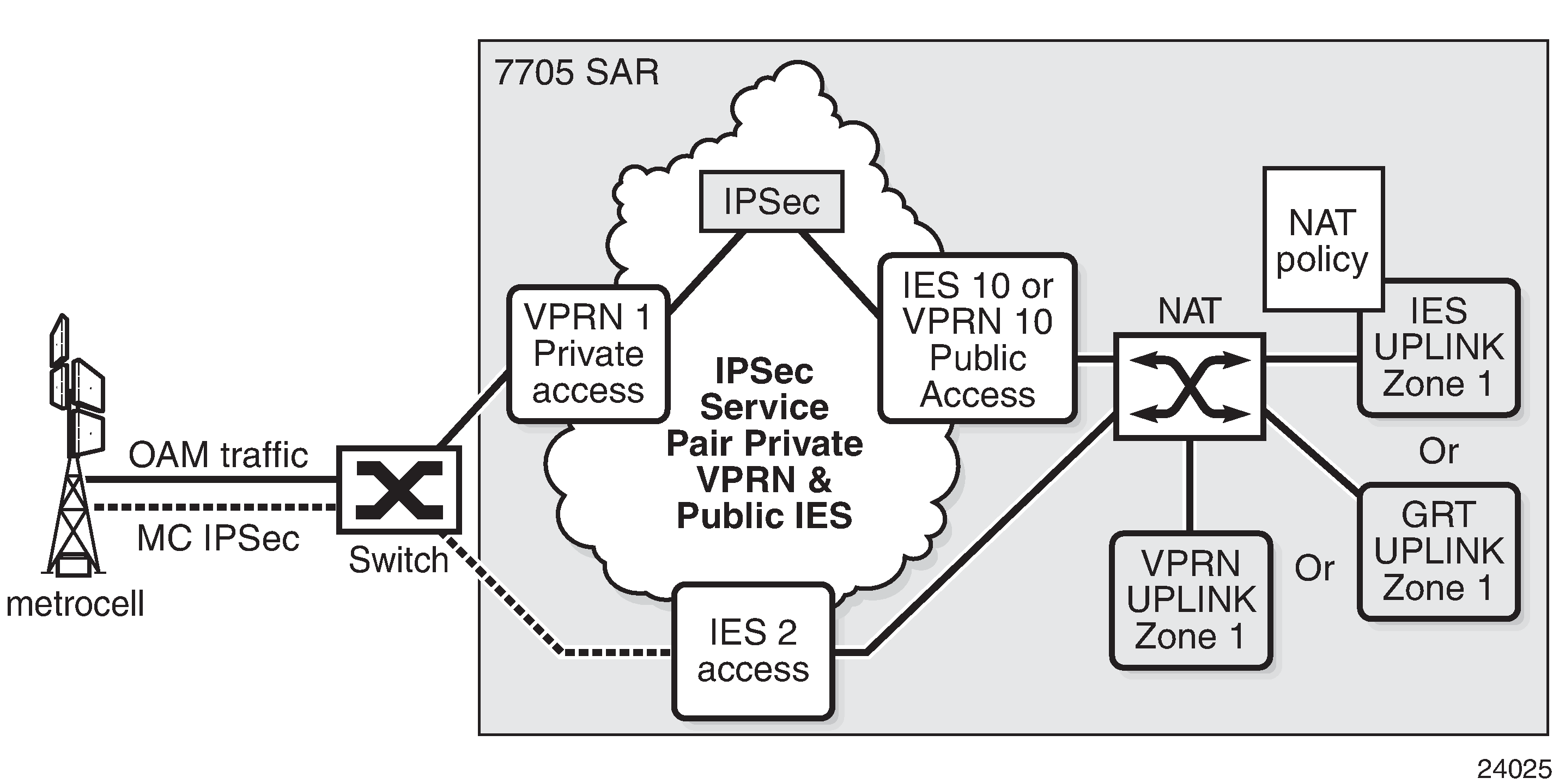
In Zone Configuration in a Mobile Backhaul Network, the OAM traffic from the metrocell is not encrypted. The OAM traffic is aggregated into a single VPRN service and IPSec functionality encrypts the OAM traffic. The encrypted traffic enters IES 10 or VPRN 10 with an IPSec header that has a routable IP destination address (typically to a security gateway) in addition to the encrypted payload. The far-end destination IP address can be reached through IES uplink zone 1, GRT uplink zone 1, or VPRN uplink zone 1. Since the traffic from IES 10 or VPRN 10 to the uplink zone crosses a zone boundary, the zone policy is applied to the uplink interface, and NAT is applied to the packet. The source IP address in the packet is replaced with the IP address of the uplink interface.
Similarly, in Zone Configuration in a Mobile Backhaul Network, traffic from the metrocell (indicated by the dashed line), is encrypted by the metrocell with a valid IP header that contains a destination IP address (typically to a security gateway). The far-end destination is reachable through IES uplink zone 1, GRT uplink zone 1, or VPRN uplink zone 1. The packet has NAT applied to it because the packet must cross a zone boundary. The source IP address of the metrocell packet that enters IES 2 is replaced with the source IP address of IES uplink zone 1 as it exits the 7705 SAR. In addition, the source UDP/TCP port may also be replaced depending on the NAT policy configured for the zone.
In both of the cases described above, NAT is applied to the IP traffic according to NAT zone policy rules configured for IES uplink zone 1, GRT uplink zone 1, or VPRN uplink zone 1.
When using NAT in conjunction with IPSec, all IPSec tunnels must be configured (enabled) with NAT traversal (NAT-T) functionality. Enabling NAT-T on IPSec causes an insertion of the UDP port below the IPSec IP header. This UDP port can be used by NAT to uniquely identify each IPSec tunnel.
With static destination NAT, when packets from a public domain arrive at a zone, their source and destination IP addresses are evaluated to determine from which interface within the zone the packet will egress.
Dynamic Source NAT
Source NAT can be used to create sessions from inside a private network to an outside (public) network. If an arriving IP packet on the 7705 SAR matches the NAT policy rules, an internal mapping is created between the inside (private) source IP address/source port and an outside (public) source IP address/source port. The public IP address and port are configured in the NAT pool policy.
NAT automatically creates a reverse mapping for arriving traffic from the public domain to the private domain for the same connection. This reverse mapping is based on an outside destination IP address and destination port to an inside destination IP address and destination port.
The configurable outside NAT pool for the source IP address and source port can be either a range of addresses and ports or a unique IP address and port.
The 7705 SAR also supports a single public IP address so that all inside source IP addresses can be mapped to a single outside IP address and a range of ports. In this case, the interface name can be assigned to the NAT pool configuration. For ease of configuration, any local interfaces on the 7705 SAR can be assigned to the NAT pool (for example, local Layer 3 interfaces, loopback interfaces).
By assigning the Layer 3 interface name, the NAT pool inherits the IP address of that specific interface. For a DHCP client, the NAT pool IP address can change based on the IP address assigned to the interface by the DHCP server. If the interface IP address changes, all associated NAT sessions are cleared and re-established.
Local Traffic and NAT
Source NAT does not support self-generated traffic such as OSPF, BGP, or LDP.
Only packets transiting the 7705 SAR node have NAT applied to them. Any packet arriving on the 7705 SAR with a local IP address will be checked against active NAT sessions on the datapath (6-tuple lookup), and if there is no match, the packet is sent to the CSM for processing as local traffic.
Port Forwarding (Static Destination NAT)
Port forwarding consists of mapping an outside destination port to an inside destination IP address and port. For example, a packet arriving from outside on port X and using a UDP protocol (from any IP address) is mapped to an inside destination port and destination IP address.
A typical use of port forwarding is shown in Static Port Forwarding with NAT. Each inside application is uniquely accessible via an outside port. For example, the surveillance camera behind the 7705 SAR can be reached via the UDP protocol and port 50. Any packet from any IP address arriving on destination port 50 is mapped to an internal destination IP address of 192.168.1.3 and destination port 50.
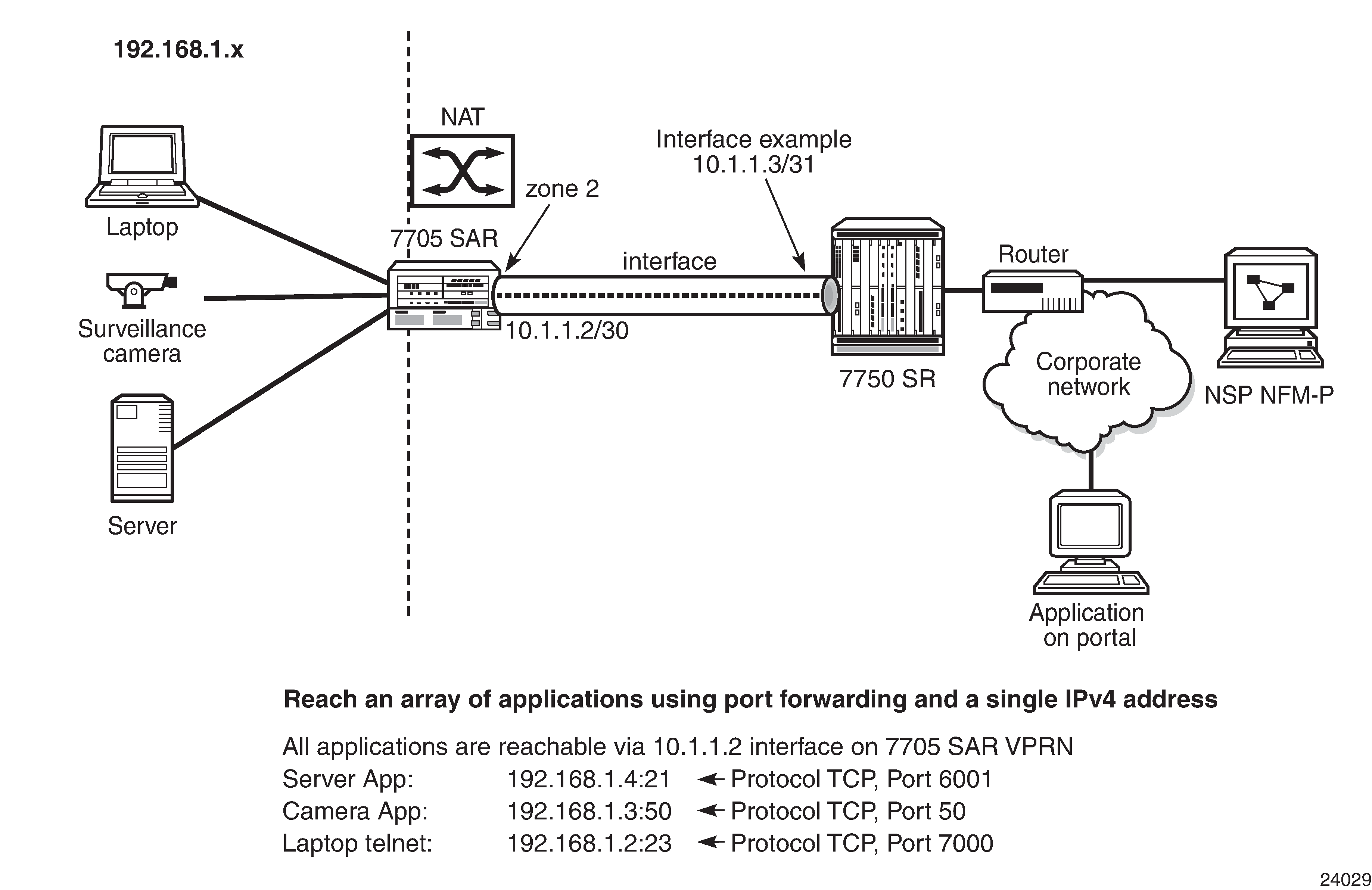
Static port forwarding can provide accessibility to applications behind a single IP address. Each application can be uniquely accessed via the public IP address and the destination port for that application.
Matching criteria for port forwarding includes local interface IP address, source IP address, and source UDP/TCP port.
Static One-to-One NAT
With static one-to-one NAT, NAT is performed on packets traveling from an inside (private) interface to an outside (public) interface or from an outside interface to an inside interface. Static one-to-one NAT can be applied to a single IP address or a subnet of IP addresses and is performed on the IP header of a packet, not on the UDP/TCP port.
Mapping statements, or entries, can be configured to map an IP address range to a specific IP address. The direction of the NAT mapping entry dictates whether NAT is performed on a packet source IP address or subnet or on a packet destination IP address or subnet. The 7705 SAR supports inside mapping entries that map an inside IP address range to an outside IP address range sequentially.
With an inside mapping entry, the following points apply:
Packets that originate from an inside interface and are destined for an inside interface are forwarded without any NAT being applied.
If there is a matching one-to-one NAT mapping entry, packets that originate from an inside interface and are destined for an outside interface undergo static one-to-one NAT where NAT changes the source IP address of the packet IP header. The packet is forwarded whether or not a NAT mapping entry is found unless the drop-packets-without-nat-entry command is enabled. When a mapping entry is not found and the drop-packets-without-nat-entry command is enabled, the packet is not forwarded.
If there is a matching one-to-one NAT mapping entry, packets that originate from an outside interface and are destined for an inside interface undergo static one-to-one NAT where NAT changes the destination IP address of the packet IP header. The packet is forwarded whether or not a NAT mapping entry is found unless the drop-packets-without-nat-entry command is enabled. When a mapping entry is not found and the drop-packets-without-nat-entry command is enabled, the packet is not forwarded.
Packets that originate from an outside interface and are destined for an outside interface are forwarded without any NAT being applied.
Static one-to-one NAT is performed on packets that transit the node and match the mapping entry. These packets include IPSec packets, GRE packets, and IP packets. NAT can be performed on packets from a single inside interface or multiple inside interfaces that are traveling to a single outside interface or multiple outside interfaces.
Static one-to-one NAT is not performed on packets that are destined for the node nor is it performed on self-generated traffic or on routing protocols. The 7705 SAR blocks static one-to-one NAT to a public prefix that has the same IP subnet as a local interface.
Static one-to-one NAT is supported in the GRT and in VPRNs. For information about VPRNs and one-to-one NAT, see the 7705 SAR Services Guide, ‟Static One-to-One NAT and VPRN”.
GRT Interfaces Supported for Static One-to-One NAT lists the types of outside and inside interfaces that are supported in the GRT for static one-to-one NAT.
GRT Interface Type |
Outside |
Inside |
|---|---|---|
Network interface |
Yes |
No |
IES interface |
Yes |
Yes |
IES r-VPLS interface |
Yes |
Yes |
IES Layer 3 spoke SDP interface |
Yes |
Yes |
IPSec public interface |
n/a |
n/a |
Static One-to-One NAT and ICMP
Typically, the original packet in a flow is embedded in an ICMP Error packet. When static one-to-one NAT is configured, the payload of the ICMP Error packet is modified based on the NAT mapping.
Static One-to-One NAT and FTP
Static one-to-one NAT does not modify the IP address of FTP control packets.
Static One-to-One NAT and Firewall Security
Static one-to-one NAT and firewall security zones can be configured simultaneously. A firewall zone can include static one-to-one NAT inside interfaces or static one-to-one NAT outside interfaces. However, when a firewall security policy is used by a firewall zone, any IP address referenced in the policy must be based on the inside addressing scheme if the address involves NAT mapping, regardless of whether the interface under the firewall zone is a one-to-one NAT inside interface or outside interface.
Static One-to-one NAT and NPAT
Static one-to-one NAT and network port address translation (NPAT) cannot coexist within the same routing instance. However, they can coexist in an IPSec configuration when static one-to-one NAT is configured for the IPSec private service and NPAT is configured for an IPSec public service that is enabled with NAT-T.
Static One-to-One NAT Route Leaking to IGP or BGP
Static one-to-one NAT installs NAT routes in the routing table. By default, these routes are not advertised to the network. For example, if a user configures a NAT mapping entry that is not using a local interface IP address as its public NAT prefix, the NAT routes will be installed in the routing table but are not advertised to the network. For these routes, route policies can be used to leak one-to-one NAT routes to IGP or BGP.
Proxy ARP can be used to resolve the MAC addresses of these non-local NAT routes.
PBR and MFC
Both policy-based routing (PBR) and multi-field classification (MFC) are available when static one-to-one NAT is configured. PBR and MFC are applied to packets before the packets undergo NAT.
Cflowd and Mirroring
When static one-to-one NAT is configured, the original packets received on ingress will be used for cflowd and the transformed packets sent on egress will be shown for mirroring.
Private IP Address Ping, Traceroute, and Packet Forwarding
When static one-to-one NAT is configured, if a packet arrives on an outside interface and is destined for an inside IP address, it is not forwarded to the inside IP address; instead, it is dropped.
Similarly, if a ping or traceroute packet arrives from an outside interface and is destined for an inside IP address, the packet is not forwarded for security reasons.
It is recommended that operators set up ingress ACLs and security zones on the outside interface to ensure full security of the inside network.
Fragmentation
The 7705 SAR supports static one-to-one NAT for fragmented packets.
Multi-Chassis Firewall
Multi-chassis firewall synchronizes firewall and NAT states between two 7705 SAR routers. Both routers can have traffic traversing them, but they create a single firewall-and-NAT database on one router, known as the master. That database is synchronized and shared with the second router, known as the slave. If one firewall in a multi-chassis firewall fails, all the known UDP/TCP sessions and states are present on the other chassis. The connection can therefore continue transmitting traffic on a 5-tuple session without re-establishing the state of the session. For example, if there is a TCP connection on the first firewall that has gone through the three states of TCP, that information is synchronized to the second firewall. If there is a failure on the first firewall where the session originally was established and the traffic gets rerouted to the second firewall in the pair, the second firewall can forward the traffic on the same TCP connection without any interruption because it knows the state of the connection.
Multi-chassis firewall is supported on the following cards and platforms:
on the 7705 SAR-8 Shelf V2 and the 7705 SAR-18:
2-port 10GigE (Ethernet) Adapter card
6-port Ethernet 10Gbps Adapter card
8-port Gigabit Ethernet Adapter card, version 3
10-port 1GigE/1-port 10GigE X-Adapter card, version 2 (7705 SAR-18 only)
7705 SAR-Ax
7705 SAR-H
7705 SAR-Hc
7705 SAR-Wx
7705 SAR-X
All GRT and VPRN-based firewall functionality is supported in multi-chassis mode except for strict TCP and ALG. As well, in order for NAT to work in multi-chassis firewall and to have the same NAT state between the two firewalls, a loopback interface must be used. See Multi-Chassis NAT for more information.
The 7705 SAR uses a multi-chassis link (MCL) to connect the two firewalls in a multi-chassis configuration. The MCL must be a static route to the peer IP address.
The parameters that define the MCL are configured in the config>redundancy> multi-chassis>peer>mc-firewall context. See ‟High Availability (Redundancy) Commands” in the 7705 SAR Basic System Configuration Guide for command descriptions and syntax.
Multi-Chassis Firewall Configuration
The steps below outline how to configure a multi-chassis firewall.
On both routers, configure security profile, security policy, host group, and application group parameters. The parameter settings must be identical on both routers. See Security Policy Commands for information about configuring these parameters.
On both routers, configure identical security zone parameters so that the routers have the same zone ID on the same service ID and service type, the same NAT pool settings, and the same zone limits for inbound and outbound firewall sessions. The service ID and service type apply only to security zone configuration in the VPRN or IES context. For information about configuring security zone parameters in the VPRN context or in the IES context, see ‟VPRN Security Zone Configuration Commands” or ‟IES Security Zone Configuration Commands” in the 7705 SAR Services Guide. For information about configuring security zone parameters in the base router context, see Router Security Zone Configuration Commands.
On both routers, configure the multi-chassis firewall by configuring the following multi-chassis firewall peer parameters: the peer IP address, the system priority, and optional encryption or authentication parameters. For information about configuring these parameters, see ‟High Availability (Redundancy) Commands” in the 7705 SAR Basic System Configuration Guide.
On both routers, issue the config>redundancy>multi-chassis>peer>mc-firewall>no shutdown command to initiate communication between the peers and enable the master and slave selection. For more information about master and slave, see Multi-Chassis Firewall Master/Slave Selection and Policy and Session Database Synchronization.
Issue the admin save command on each router to save the configuration.
Multi-Chassis Firewall Master/Slave Selection and Policy and Session Database Synchronization
Determining which router will be the master and which will be the slave is based on the system priority configured using the config>redundancy>multi-chassis>peer>mc-firewall>system-priority command. The router configured with the lower system priority becomes the master. If both routers have the same system priority, the router with the lowest MAC address becomes the master.
When the MCL is established and the master and slave routers are determined, the master router synchronizes its security policy configuration to the slave router over the MCL. This synchronization overwrites any security policy configuration on the slave.
In addition, the master synchronizes its session database to the slave. This synchronization is for all established security and NAT sessions. The master does not synchronize any half-open sessions to the slave. This synchronization overwrites the session database on the slave.
If policy synchronization fails, all security sessions are terminated and the security policy configuration on the slave router will be in an incomplete state. A policy synchronization flag on the master remains cleared until synchronization resumes. When synchronization completes, the policy synchronization flag changes to set. A corresponding log event is raised on the master router when the policy synchronization flag changes state.
Security zone and NAT pool information is not synchronized from the master to the slave. These parameters must be configured with identical settings on each router.
Processing New Traffic Signatures and Connections on a Multi-Chassis Firewall
When the firewall database between the master and slave has been synchronized, the firewalls on both routers can process existing connections and signatures for arriving packets. However, the master firewall must create a datapath signature in the firewall database for each new connection.
If there is no datapath firewall database, all traffic from both the slave and master router is forwarded to the CSM on the master router. The slave router forwards its packets to the master CSM over the MCL. The master CSM examines the packet against the firewall security policy and creates a 5-tuple signature including the action (drop or forward).
This signature is downloaded to the datapath firewall database on the master and to the datapath firewall database on the slave over the MCL. From this point on, both the master and slave have the packet signature and action in their datapath firewall database.
Adding, Modifying, and Deleting a Firewall Security Policy in a Multi-Chassis Firewall
The following steps outline how to add a new firewall security policy or modify an existing one in a multi-chassis firewall configuration.
On the master router, use the begin command to start an editing session.
In the config>security context, configure settings for security profile, host-group, app-group, and/or policy (rule) commands on the master router.
When the changes are complete, issue the commit command on the master router to save the policy settings.
The configuration is automatically synchronized to the slave router.
Issue the admin save command on the master and slave routers to save the configuration.
The steps below outline how to delete a firewall security policy in a multi-chassis firewall configuration.
Ensure that the policy is not being used by a zone on either the master or slave router.
On the master router, use the begin command to start an editing session.
Delete a policy from the master router using the config>security>no policy policy-id | policy-name command.
When the policy is deleted, issue the commit command on the master router to save the change.
The change is automatically synchronized to the slave router.
Issue the admin save command on the master and slave routers to save the configuration.
Adding, Modifying, and Deleting a Zone in a Multi-Chassis Firewall
In a multi-chassis firewall, zone configuration is not synchronized between the master and slave routers. All zone-level configuration, including the addition and deletion of zones, must be performed on each router separately.
The master and slave routers identify zones based on their assigned zone IDs. In the VPRN and IES service contexts, zone IDs must match and be assigned to the same service ID and service type on both the master and the slave routers. In all contexts (baser router, IES, and VPRN), all zone parameter configurations must match on both routers, except for the assigned interfaces.
Adding a Zone
The following steps outline how to add a new zone in a multi-chassis firewall configuration.
On the master and slave routers, disable the multi-chassis peer using the config>redundancy>multi-chassis>peer>mc-firewall>shutdown command.
On the master and slave routers, create a new zone.
In the base router context, use the config>router>zone zone-id | zone-name create command.
In the VPRN or IES contexts, use the config>service>vprn | ies>zone {zone-id | name} [create] command.
On the master and slave routers, put the new zone into a draft state.
In the base router context, use the config>router>zone zone-id | zone-name begin command.
In the VPRN or IES contexts, use the config>service>vprn | ies>zone {zone-id | name} begin command.
On the master and slave routers, assign a corresponding interface to the new zone.
In the base router context, use the config>router>zone>interface interface-name command.
In the VPRN or IES contexts, use the config>service>vprn | ies>zone>interface interface-name command.
On the master and slave routers, assign a policy to the new zone.
In the base router context, use the config>router>zone>policy policy-id | policy-name command.
In the VPRN or IES contexts, use the config>service>vprn | ies>zone>policy policy-id | policy-name command.
The policy-to-zone assignment on the two routers must match.
When changes are complete, save the changes on each router.
In the base router context, use the config>router>zone zone-id | zone-name commit command.
In the VPRN or IES contexts, use the config>service>vprn | ies>zone {zone-id | name} commit command.
On the master and slave routers, enable the multi-chassis peer using the config>redundancy>multi-chassis>peer>mc-firewall>no shutdown command.
Issue the admin save command on the master and slave routers to save the configuration.
Modifying a Zone
The following steps outline how to modify a zone in a multi-chassis firewall configuration.
On the master and slave routers, disable the multi-chassis peer using the config>redundancy>multi-chassis>peer>mc-firewall>shutdown command.
On the master and slave routers, put the zone into a draft state.
In the base router context, use the config>router>zone zone-id | zone-name begin command.
In the VPRN or IES contexts, use the config>service>vprn | ies>zone {zone-id | name} begin command.
On the master and slave routers, change the zone interface, inbound and outbound limit parameters, NAT pool parameters, and/or policy-to-zone assignment.
When changes are complete, save the changes on each router.
In the base router context, use the config>router>zone zone-id | zone-name commit command.
In the VPRN or IES contexts, use the config>service>vprn | ies>zone {zone-id | name} commit command.
On the master and slave routers, enable the multi-chassis peer using the config>redundancy>multi-chassis>peer>mc-firewall>no shutdown command.
Issue the admin save command on the master and slave routers to save the configuration.
Deleting a Zone
The following steps outline how to delete a zone in a multi-chassis firewall configuration.
On the master and slave routers, disable the multi-chassis peer using the config>redundancy>multi-chassis>peer>mc-firewall>shutdown command.
On the master and slave routers, put the zone into a draft state.
In the base router context, use the config>router>zone zone-id | zone-name begin command.
In the VPRN or IES contexts, use the config>service>vprn | ies>zone {zone-id | name} begin command.
On the master and slave routers, remove the policy-to-zone assignment.
In the base router context, use the config>router>zone>no policy command.
In the VPRN or IES context, use the config>service>vprn | ies>zone>no policy command.
When changes are complete, save the changes on each router.
In the base router context, use the config>router>zone zone-id | zone-name commit command.
In the VPRN or IES contexts, use the config>service>vprn | ies>zone {zone-id | name} commit command.
On the master and slave routers, delete the zone.
In the base router context, use the config>router>no zone zone-id | zone-name command.
In the VPRN or IES context, use the config>service>vprn | ies>no zone zone-id | zone-name command.
On the master and slave routers, enable the multi-chassis peer using the config>redundancy>multi-chassis>peer>mc-firewall>no shutdown command.
Issue the admin save command on the master and slave routers to save the configuration.
Multi-Chassis Firewall Security Logging
Security logging parameters and settings must match on the master and slave routers. To configure logging for each entry of a security policy or for a zone, the policy and zone must be put into a draft state using the begin command. When the changes are complete, the commit command must be used to save them to the firewall database.
If a multi-chassis firewall activity switch occurs, the existing security sessions on the new master router do not retain their logging attributes. Instead, new sessions that are established after the switch will assume the configured logging attributes.
On the CLI, security session status, timers, and details are shown only for the master. Session statistics for each 5-tuple signature are shown on both the master and slave.
MCL Failure
If the MCL goes down between the two firewalls for any reason, the two firewalls will function as standalone firewalls. They will each learn and process new connections arriving on the firewall, compare the connections against their own CSM firewall security policies, and program their respective databases accordingly.
When the MCL is re-established, the slave firewall will become synchronized to the master firewall. Previously learned signatures and previously provisioned configurations on the slave are overwritten with those on the master firewall.
Multi-Chassis NAT
Only source NAT is supported in multi-chassis firewall configuration. For NAT to function correctly, a loopback address with the same IP address must be created on both firewall routers. This IP address should be in the NAT pool for source NAT so that return traffic can be routed to either router and undergo reverse NAT at either firewall. Proxy ARP can be created for this loopback address. See Proxy ARP for information.
MCL Encryption
The multi-chassis firewall messages on the MCL between the master and slave can be encrypted and authenticated. Encryption and authentication are important on this link in order to avoid man-in-the-middle attacks where hackers can insert signature packets and create new unwanted states in the firewall. The MCL is encrypted using the config>redundancy>multi-chassis>peer>mc-firewall>encryption command.
The 7705 SAR supports AES128 and AED256 encryption algorithms and SHA256 and SHA512 authentication algorithms.
A security association (SA) contains the keys that are required to encrypt and authenticate the link. A security association is uniquely identified by a security parameter index (SPI). There are two SPIs for key rollover. On egress, only the active outbound SA is used for encryption and authentication. The active-outbound-sa num command identifies the active SA, where num is the SPI for that SA. On ingress, decryption is done using both SPIs. Using both SPIs means that packets can be decrypted using the current and previous keys, allowing for a smooth transition.
Using the 7705 SAR as Residential or Business CPE
The 7705 SAR can be used as a residential or business CPE device for the purposes of ISP backhaul. With GPON, DSL, or cable-based residential or business backhaul services, specifically, ISPs typically terminate subscribers on a broadband network gateway to assign IP addresses, and to enforce authentication, authorization, and accounting before the customer traffic is routed for Internet access. By making use of the 7705 SAR as a CPE device, ISP backhaul infrastructure can be used to connect an eNodeB, such as a voice-free metrocell, to a network. The 7705 SAR continues to support a wide array of services, including IP-VPN, Ethernet, TDM, PWs, and VPLS services, over this backhaul by making use of GRE or IP tunnels. An example of a network using a 7705 SAR as a CPE device is shown in Network Using 7705 SAR as a CPE Device.
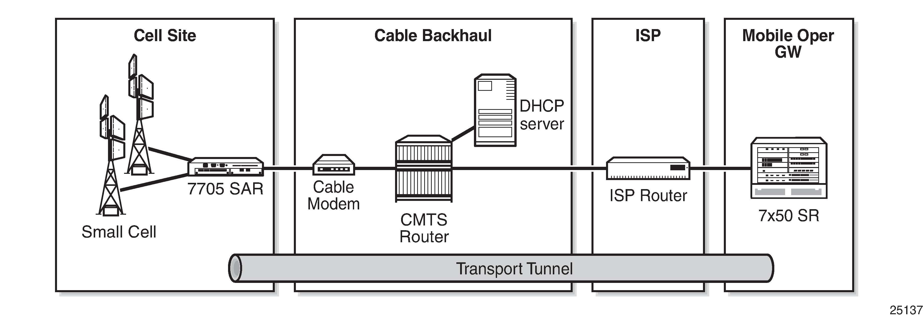
Residential or business CPE functionality is available through the use of:
unnumbered interfaces
In normal operation, the 7705 SAR requires at least two IP addresses: a system IP address and an uplink interface IP address. However, ISPs typically assign a single IP address per connection for residential or business backhaul services, due to cost or architectural issues. Configuring the 7705 SAR to use unnumbered interfaces alleviates this issue.
See Unnumbered Interfaces for more information.
dynamic assignment of system IP addresses through DHCP
A 7705 SAR using unnumbered interfaces does not have a configured uplink interface IP address, as the uplink interface identifier is tied to the system IP address. In residential and business backhaul, the system IP address must be assigned dynamically. The system IP address can be assigned dynamically using DHCP when the 7705 SAR is acting as a DHCP client and the DHCP server-facing interface is unnumbered.
automatic provisioning of a default gateway
As part of a DHCP OFFER message, the ISP also offers a default gateway IP address to the client. The 7705 SAR, as the client, must set up a default route pointing to the default gateway once the gateway IP is offered via Option 3. The default gateway points to the network interface, which, as the DHCP server-facing interface, is unnumbered.
Router Configuration Process Overview
The following figure displays the process to configure basic router parameters.
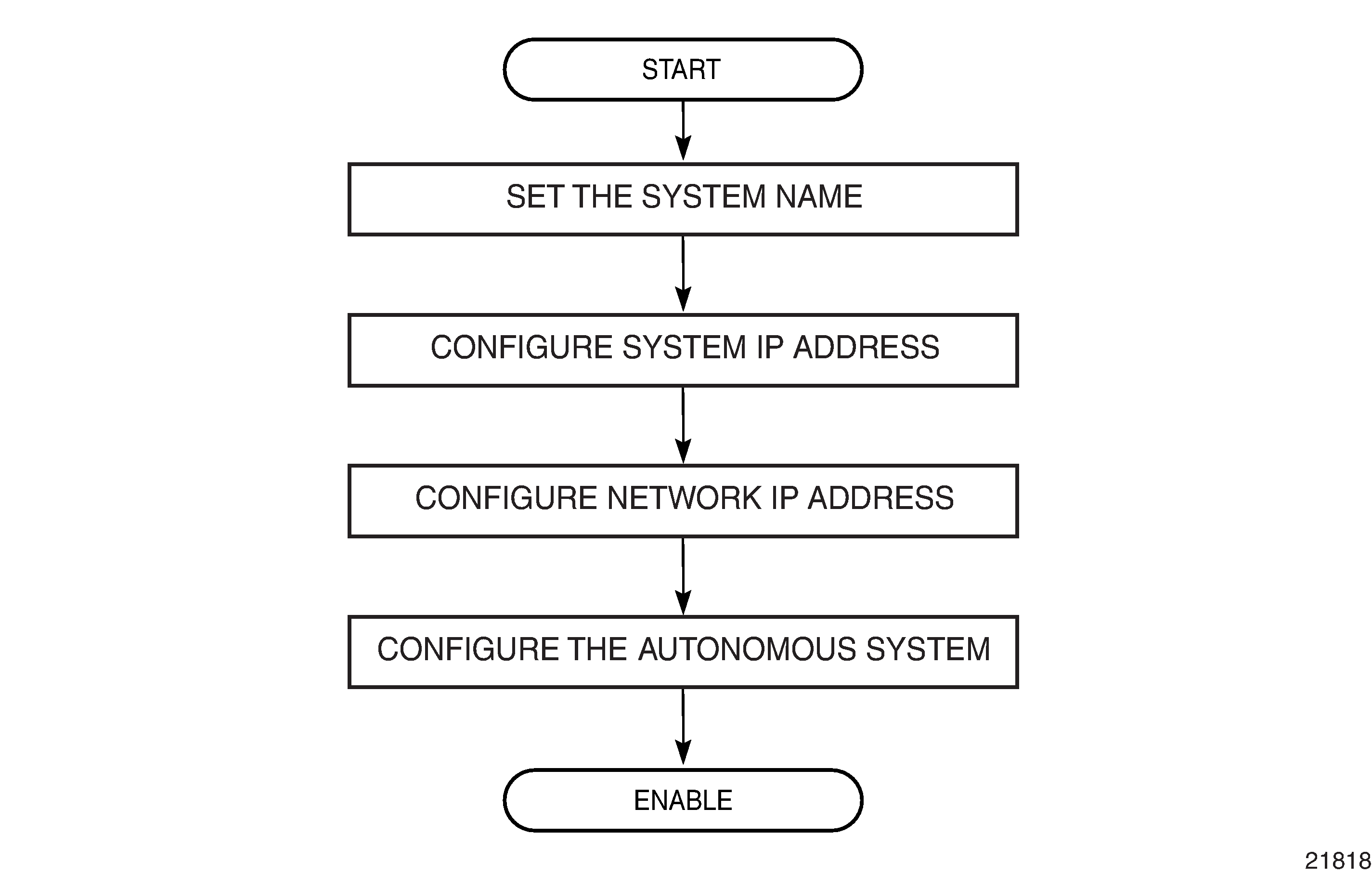
Configuration Notes
The following information describes router configuration guidelines and caveats.
A system interface and associated IP address must be specified.
Boot options file (BOF) parameters must be configured prior to configuring router parameters.
Configuring an IP Router with CLI
This section provides information to configure an IP router.
Topics in this section include:
Router Configuration Overview
On a 7705 SAR, an interface is a logical named entity. An interface is created by specifying an interface name under the config>router context, the global router configuration context where objects like static routes and dynamic routing are defined. An IP interface name can be up to 32 alphanumeric characters, must start with a letter, and is case-sensitive; for example, the interface name ‟1.1.1.1” is not allowed, but ‟int-1.1.1.1” is allowed.
To create an interface on a 7705 SAR, the basic configuration tasks that must be performed are:
assign a name to the interface
associate an IP address with the interface
associate the interface with a network interface or the system interface
configure appropriate routing protocols
A system interface and network interface should both be configured unless the network interface is configured as an unnumbered interface. In that case, the network interface borrows (or links to) an IP address from another interface on the system (the system IP address, another loopback interface, or any other numbered interface), which serves as a combined system IP address and network IP address.
System Interface
A system interface is a virtual interface similar to other interfaces but with only some operational parameters. The IP address, shutdown and no shutdown attributes are the only operational parameters for the system interface.
The system interface must have an IP address with a 32-bit subnet mask. The system interface is associated with the node (such as a specific 7705 SAR), not a specific interface. The system interface is also referred to as the loopback interface. The system interface is associated during the configuration of the following entities:
LSP creation (next hop) — when configuring MPLS paths and LSPs
the addresses on a target router — to set up an LDP or OSPF session between neighbors and to configure SDPs (the system interface is the service tunnel endpoint)
The system interface is used to preserve connectivity (when alternate routes exist) and to decouple physical connectivity and reachability. If an interface carrying peering traffic fails, and there are alternative routes to the same peer system interface, peering could be either unaffected or re-established over the alternate routes. The system interface IP address is also used for pseudowire/VLL signaling (via targeted LDP).
The system interface is used as the router identifier if a router ID has not been explicitly configured.
Network Interface
A network interface can be configured on a physical or logical port.
On the 2-port 10GigE (Ethernet) Adapter card/module, the network interface can only be created on the v-port (not the ring ports).
Basic Configuration
The most basic router configuration must have the following:
system name
system address
The following example displays a router configuration.
ALU-1>config>router# info
#------------------------------------------
# Router Configuration
#------------------------------------------
    router
        interface "system"
            address 192.0.2.1/24
        exit
        interface "to-104"
            address 192.0.2.1/24
            port 1/1/1
            exit
        exit
#------------------------------------------
A:ALU-1>config#
Common Configuration Tasks
The following sections describe basic system tasks:
Configuring a System Name
Use the system command to configure a name for the device. The name is used in the prompt string. Only one system name can be configured. If multiple system names are configured, the last one configured will overwrite the previous entry.
If special characters are included in the system name string, such as spaces, #, or ?, the entire string must be enclosed within double quotes.
Use the following CLI syntax to configure the system name:
- CLI Syntax:
config# systemname system-name
- Example:
config# systemconfig>system# nameNOK-AALU-A>config>system# exit all
The following example displays the system name output.
A:ALU-A>config>system# info
#------------------------------------------
# System Configuration
#------------------------------------------
        name "NOK-A"
        location "Kanata, ON, Canada"
        snmp
        exit
        . . .
        exit
----------------------------------------------
Configuring Router IPv6 Neighbor Discovery Parameters
Use the following CLI syntax to configure IPv6 neighbor discovery parameters:
- CLI Syntax:
config# routeripv6reachable-time secondsstale-time seconds
- Example:
config# routerconfig>router# ipv6config>router>ipv6# reachable-time 30config>router>ipv6# stale-time 14400config>router>ipv6# exitconfig>router# exit
The following example displays IPv6 neighbor discovery parameters output.
A:ALU-A>config>router# info
#------------------------------------------
# IP Configuration
#------------------------------------------
        ...
            reachable-time 30
            stale-time 14400
        exit
        ...
Configuring Interfaces
The following command sequences create a system interface and a logical IP interface. The system interface assigns an IP address to the interface, and then associates the IP interface with a physical port. The logical interface can associate attributes like an IP address or port.
The system interface cannot be deleted.
Configuring a System Interface
Use the following CLI syntax to configure a system interface:
- CLI Syntax:
config>routerinterface ip-int-nameaddress {ip-addr/mask-length}| {ip-addr/netmask}
- Example:
config>router# interface ‟system”config>router>if# address 192.168.0.0/16config>router>if# exit
Configuring a Network Interface
On the 2-port 10GigE (Ethernet) Adapter card/module, a network address is assigned to the v-port only.
Use the following CLI syntax to configure a network interface:
- CLI Syntax:
config>routerinterface ip-int-nameaddress {ip-addr/mask-length | ip-addr/netmask | dhcp} [client-identifier [ascii-value | interface-name]] [vendor-class-id vendor-class-id]egressagg-rate-limit agg-rate [cir cir-rate]filter ip ip-filter-idqueue-policy nameingressfilter ip ip-filter-idport port-name
- Example:
config>router> interface "to-NOK-2"config>router>if# address 192.168.0.1/16config>router>if# port 1/1/1config>router>if# egressconfig>router>if>egress# filter ip 12config>router>if>egress# exitconfig>router>if# ingressconfig>router>if>ingress# filter ip 10config>router>if>ingress# exitconfig>router>if# exit
The preceding syntax example shows a configuration where the address is entered manually. To have the interface enabled for dynamic address assignment, use the dhcp keyword and, optionally, assign client ID and vendor class ID.
In addition, to apply and configure a per-VLAN network egress aggregate shaper, use the queue-policy and agg-rate-limit commands.
The following example displays the IP configuration output showing the interface information.
A:ALU-A>config>router# info
#------------------------------------------
# IP Configuration
#------------------------------------------
        interface "system"
            address 192.168.0.0/16
        exit
        interface "to-NOK-2"
            address 192.168.0.1/16
            port 1/1/1
            ingress
                filter ip 10
            exit
Creating an IPv6 Network Interface
When configuring an IPv6 interface, a link-local address (fe80::x:x:x:x:x:x:x/64) is automatically generated after the CLI command ipv6 is given. If the port is already assigned to the interface when IPv6 is enabled, the link-local address is derived from the port MAC address. Otherwise, the link-local address is derived from the system MAC address.
In either case, if the configuration file is saved and the node is rebooted, the port will be assigned to the interface before IPv6 is enabled and the link-local address will be derived from the port MAC address. This means that the link-local address will change after the node is rebooted if it was derived from the system MAC address before the reboot.
To avoid having the link-local address change after a reboot, IPv6 on the interface should be configured in the following order. This will ensure that the link-local address is derived from the port MAC address and will therefore not change after a reboot.
- CLI Syntax:
config>portconfig>routerinterface ip-int-nameport port-nameipv6address ipv6-address/prefix-length [eui-64]
Configuring an Unnumbered Interface
Use the following CLI syntax to configure an unnumbered interface:
- CLI Syntax:
config>routerinterface ip-int-nameunnumbered [ip-int-name | ip-address] [dhcp] [client-identifier ascii-value | interface-name] [vendor-class-id vendor-class-id]
- Example:
config>router> interface "to-NOK-3"config>router>if# unnumbered ‟system”config>router>if# exit
The preceding syntax example shows a configuration where the address is entered manually. To have the interface enabled for dynamic assignment of the system IP address, use the dhcp keyword and, optionally, assign client ID and vendor class ID.
Configuring IPv6 Parameters
IP version 6 (IPv6) addresses are supported on:
access ports (IES); for a complete list of cards and ports that support IES IPv6 SAPs, see the 7705 SAR Services Guide, ‟IES for Customer Traffic”.
network ports (null or dot1q encapsulation) on:
2-port 10GigE (Ethernet) Adapter card (v-port only)
6-port Ethernet 10Gbps Adapter card
8-port Gigabit Ethernet Adapter card
10-port 1GigE/1-port 10GigE X-Adapter card
Packet Microwave Adapter card
Ethernet ports on the 7705 SAR-M
Ethernet ports on the 7705 SAR-A
Ethernet ports on the 7705 SAR-Ax
Ethernet ports on the 7705 SAR-Wx
7705 SAR-H
Ethernet ports on the 7705 SAR-Hc
Ethernet ports on the 7705 SAR-X
Ethernet management port
2-port 10GigE (Ethernet) module (v-port only)
4-port SAR-H Fast Ethernet module
6-port SAR-M Ethernet module
network ports on the 4-port OC3/STM1 Clear Channel Adapter card (POS encapsulation)
Use the following CLI syntax to configure IPv6 parameters:
- CLI Syntax:
config>routerinterface ip-int-nameipv6address ipv6-address/prefix-length [eui-64]bfd transmit-interval [receive receive-interval] [multiplier multiplier] [type np]icmp6 (see Configuring ICMP and ICMPv6)neighbor ipv6-address mac-addressreachable-time secondsstale-time seconds
- Example:
config>router# interface ‟ipv6-interface”config>router>if# ipv6config>router>if>ipv6>address# ip 2001:db8::1/32config>router>if>ipv6>address# exitconfig>router>if>ipv6# bfd 100 receive 100 multiplier 3 type npconfig>router>if>ipv6>bfd# exitconfig>router>if>ipv6# neighbor 2001:db8::2config>router>if>ipv6>neighbor# exitconfig>router>if>ipv6# reachable-time 30config>router>if>ipv6# stale-time 14400config>router>if>ipv6# exit
Configuring Router Advertisement
To configure the router to originate router advertisement messages, the router-advertisement command must be enabled. All other router advertisement configuration parameters are optional. Router advertisement on all IPv6-enabled interfaces will be enabled.
Use the following CLI syntax to enable router advertisement and configure router advertisement parameters:
- CLI Syntax:
config>routerrouter-advertisementinterface ip-int-namecurrent-hop-limit numbermanaged-configurationmax-advertisement-interval secondsmin-advertisement-interval secondsmtu mtu-bytesother-stateful-configurationprefix ipv6-prefix/prefix-lengthautonomouson-linkpreferred-lifetime {seconds | infinite}valid-lifetime {seconds | infinite}reachable-time milli-secondsretransmit-time milli-secondsrouter-lifetime secondsno shutdown
- Example:
config>router# router-advertisementconfig>router>router-advert# interface ‟n1”config>router>router-advert>if# prefix 3::/64config>router>router-advert>if>prefix# autonomousconfig>router>router-advert>if>prefix# on-linkconfig>router>router-advert>if>prefix# preferred-lifetime 604800config>router>router-advert>if>prefix# valid-lifetime 2592000
The following example displays a router advertisement configuration:
A:ALU-A>config>router>router-advert# info
------------------------------------------
            interface ‟n1”
                prefix 3::/64
                exit
                no shutdown
------------------------------------------
A:ALU-A>config>router>router-advert# interface n1
A:ALU-A>config>router>router-advert>if# prefix 3::/64
A:ALU-A>config>router>router-advert>if>prefix# into detail
------------------------------------------

                      autonomous
                      on-link
                      preferred-lifetime 604800
                      valid-lifetime 2592000
------------------------------------------
A:ALU-A>config>router>router-advert>if>prefix#
Configuring ECMP
ECMP (Equal-Cost Multipath Protocol) refers to the distribution of packets over two or more outgoing links that share the same routing cost. The 7705 SAR load-balances traffic over multiple equal-cost links with a hashing algorithm that may use header fields from incoming packets to calculate which link to use. Adding additional fields to the algorithm increases the randomness of the results and ensures a more even distribution of packets across available links. ECMP is supported on static routes and dynamic (OSPF, IS-IS, and BGP) routes. The 7705 SAR supports ECMP for LDP and IP traffic.
If multiple routes are learned with an identical preference using the same protocol, the lowest-cost route is used. If multiple routes are learned with an identical preference using the same protocol and the costs (metrics) are equal, the decision of which route to use is determined by the configuration of ECMP in the config>router context.
Use the following CLI syntax to configure ECMP, enable it and specify the maximum number of routes to be used for route sharing (up to 8):
- CLI Syntax:
config>routerecmp max-ecmp-routes
- Example:
config>router# ecmp 7config>router# exit
Configuring Static Routes
The 7705 SAR supports both static routes and dynamic routing to next-hop addresses.
For information about configuring OSPF, RIP, IS-IS, and BGP routing, see the 7705 SAR Routing Protocols Guide.
Only one next-hop IP address can be specified per IP interface for static routes.
Use the following CLI syntax to create a static route entry. The mcast keyword indicates that the static route entry being configured is used for the multicast table only. The black-hole, indirect, and next-hop commands provide access to configure their parameters. Unless no shutdown is specified, the static-route-entry will be created in a shutdown state.
- CLI Syntax:
config>router>static-route-entry {ip-prefix/prefix-length} [mcast]black-hole {ip-int-name | ip-address | ipv6-address}[no] description description-string[no] metric metric[no] preference preference[no] shutdown[no] tag tagindirect [ip-address][no] description description-string[no] metric metric[no] preference preference[no] shutdown[no] tag tagtunnel-next-hop[no] disallow-igpresolution {any | disabled | filter}resolution-filter[no] ldp[no] rsvp-te[no] lsp lsp-name[no] sr-isis[no] sr-ospf[no] sr-te[no] lsp lsp-namenext-hop {ip-int-name | ip-address | ipv6-address}[no] bfd-enable[no] description description-string[no] ldp-sync[no] metric metric[no] preference preference[no] shutdown[no] tag tag
- Example:
config>router# static-route-entry 192.168.0.10/16static-route-entry# next-hop 192.168.0.20next-hop# metric 1next-hop# preference 5next-hop# ldp-syncnext-hop# tag 20next-hop# no shutdown
Configuring or Deriving a Router ID
The router ID defaults to the address specified in the system interface command. If the system interface is not configured with an IP address, the router ID inherits the last 4 bytes of the MAC address. Alternatively, the router ID can be explicitly configured with the config>router>router-id command.
When configuring a new router ID, protocols are not automatically restarted with the new router ID. The next time a protocol is initialized, the new router ID is used. To force the new router ID, issue the shutdown and no shutdown commands for OSPF, IS-IS, or BGP, or restart the entire router.
Use the following CLI syntax to configure a router ID:
- CLI Syntax:
config>routerrouter-id ip-addressinterface ip-int-nameaddress {ip-address/mask | ip-address netmask}
The following example displays a router ID configuration:
A:ALU-B>config>router# info
#------------------------------------------
# IP Configuration
#------------------------------------------
        interface "system"
            address 192.168.0.10/16
        exit
        interface "to-103"
            address 192.168.0.20/16
            port 1/1/1
        exit
        router-id 192.168.0.0
...
#------------------------------------------
A:ALU-B>config>router#
Configuring an Autonomous System
Configuring an autonomous system is optional.
Use the following CLI syntax to configure an autonomous system:
- CLI Syntax:
config>routerautonomous-system as-number
The following displays an autonomous system configuration example:
A;ALU-B>config>router# info
#------------------------------------------
# IP Configuration
#------------------------------------------
     interface "system"
          address 192.168.0.10/16
     exit
     interface "to-104"
          address 192.168.0.30/16
          port 1/1/1
     exit
     exit
     autonomous-system 100
     router-id 192.168.0.1
#------------------------------------------
Configuring ICMP and ICMPv6
Use the following CLI syntax to configure ICMP for the router:
- CLI Syntax:
config>routerinterface ip-int-nameicmpmask-replyttl-expired number secondsunreachables number seconds
The number and seconds parameters represent how many of each of these types of ICMP errors the node will generate in the specified interval on the specified interface.
- Example:
config>router>if# icmpconfig>router>if>icmp# mask-replyconfig>router>if>icmp# ttl-expired 100 20config>router>if>icmp# unreachables 100 20
Use the following CLI syntax to configure ICMPv6 for the router:
- CLI Syntax:
config>routerinterface ip-int-nameipv6icmp6packet-too-big number secondsparam-problem number secondstime-exceeded number secondsunreachables number seconds
The number and seconds parameters represent how many of each of these types of ICMPv6 errors the node will generate in the specified interval on the specified interface.
- Example:
config>router>if>ipv6# icmp6config>router>if>ipv6>icmp6# packet-too-big 100 20config>router>if>ipv6>icmp6# param-problem 100 20config>router>if>ipv6>icmp6# time-exceeded 100 20config>router>if>ipv6>icmp6# unreachables 100 20
Configuring a DHCP Relay Agent
Use the following CLI syntax to configure the router as a DHCP Relay agent:
- CLI Syntax:
config>routerinterface ip-int-namedhcpdescription description-stringgi-address ip-address [src-ip-addr]optionaction {replace | drop | keep}circuit-id [ascii-tuple | port-id | if-name]copy-82remote-id [mac | string string]server server1 [server2...(up to 8 max)]no shutdownno shutdown
- Example:
A:ALU-41>config>router# interface ‟DHCP_interface”A:ALU-41>config>router>if$ dhcp optionA:ALU-41>config>router>if>dhcp>option$ circuit-id ascii-tupleA:ALU-41>config>router>if>dhcp>option$ exit
The following example displays the router DHCP Relay agent creation output.
A:ALU-41>config>router>if# info detail
-------------------------------------------
...
             dhcp
                  shutdown
                  no description
                  no gi-address
                  option
                      action keep
                      circuit-id ascii-tuple
                      no remote-id
                      no copy-82
                  exit
                  no server
             no shutdown...
-------------------------------------
Configuring Proxy ARP
To configure proxy ARP, you must first:
configure a prefix list in the config>router>policy-options>prefix-list context
configure a route policy statement in the config>router>policy-options>policy-statement context and apply the prefix list
in the config>router>policy-options>policy-statement>entry>to context, specify the host source addresses for which ARP requests can or cannot be forwarded to non-local networks, depending on the specified action
in the config>router>policy-options>policy-statement>entry>from context, specify the network prefixes that ARP requests will or will not be forwarded to, depending on the specified action if a match is found
- CLI Syntax:
config>router>policy-optionsbegincommitabortprefix-list nameprefix ip-prefix/mask [exact | longer | through length | prefix-length-range length1-length2]policy-statement namedefault-action {accept | next-entry | next-policy | reject}entry entry-idaction {accept | next-entry | next-policy | reject}fromprefix-list name [name...(up to 5 max)]toprefix-list name [name...(up to 5 max)]
The following example displays the proxy ARP configuration output.
A:ALU-B>config>router>policy-options# info
----------------------------------------------
            prefix-list "prefixlist1"
                prefix 10.2.2.0/24 exact
            exit
            policy-statement "proxyARPpolicy"
                entry 1
                    from
                         prefix-list ‟prefix-list1”
                    exit
                    to
                         prefix-list ‟prefix-list1”
                    exit
                    action accept
                    exit
                exit
                default-action reject
                exit
            exit
----------------------------------------------
For more information about route policies, see Route Policies.
Apply the policy statement to the proxy ARP policy in the config>router>if>proxy-arp-policy context.
- CLI Syntax:
config>routerinterface ip-int-nameproxy-arp-policy policy-name [policy-name...(up to 5 max)]
The following example displays the router interface proxy ARP configuration.
A:ALU-41>config>router>if# info
-------------------------------------------
...
             address 192.168.0.255/16
             remote-proxy-arp
             proxy-arp-policy ‟proxyARPpolicy”
-------------------------------------------
Configuring a Security Zone
To configure NAT or firewall security functionality, you must:
configure a NAT or firewall security profile and policy in the config>security context
in the config>security>profile context, specify the timeouts for the TCP/UDP/ICMP protocols and configure logging and application assurance parameters. This step is optional. If you do not configure the profile, a default profile is assigned.
in the config>security>policy context, configure a security policy, and specify the match criteria and the action to be applied to a packet if a match is found
configure a security zone and apply the policy ID to the zone, as shown in the CLI syntax below
- CLI Syntax:
config>routerzone zone-id [create]abortbegincommitdescription description-stringinterface ip-int-name [create]name zone-namenatpool pool-id [create]description description-stringdirection {zone-outbound | zone-inbound | both}entry entry-id [create]ip-address ip-address [to ip-address] interface ip-int-nameport port [to port] interface ip-int-namename pool-namepolicy policy-id | policy-nameshutdown
The following example displays a NAT zone configuration output.
A:ALU-B>config>router# info
----------------------------------------------
        configure
            router
                zone 1 create
                begin
                    name ‟GRT zone”
                    description ‟uplink zone to public”
                    nat
                        pool 1 create
                            description "pool 1"
                            direction zone-outbound
                            entry 1 create
                                ip-addr 198.51.100.1
                                port 5000 to 6000
                            exit
                        exit
                    exit
                    policy 1
                    commit
                exit
                no-shutdown
----------------------------------------------
A:ALU-B>config>router#
Configuring Security Logging
The 7705 SAR supports rule-based logging (that is, logging for each entry of a security policy) and zone-based logging.
Logging is suppressed by default. To enable either rule-based logging or zone-based logging, logging must be configured as part of the security policy configuration.
Rule-Based Security Logging
If a packet does not match any of the rules in a security policy, the packet is dropped from a security session because the default security policy action is to reject non-matching packets. With rule-based logging, in order to see that event in the event log, the policy must be configured with a rule to log rejected, non-matching packets to the log-id, and this rule must be configured as the last entry in the policy.
Use the following CLI syntax to configure rule-based security logging:
- CLI Syntax:
config>securityloggingprofile {profile-id | profile-name} [create]description description-stringevent-control event-type [event event] {suppress | throttle | off}name nameexitlog-id {log-id | log-name} [create]description description-stringdestination {memory [size] | syslog syslog-id}name nameprofile {logging-profile-id | logging- profile-name}no shutdownexitexitbeginprofile {profile-id | profile-name} [create]name profile-namedescription description-stringapplicationassurancedns[no] reply-onlyicmp[no] limit-type3request limit packetsipoptions {permit ip-option-mask | permit-any}options ip-option-name [ip-option-name]tcp[no] strictexitexitexittimeoutsexitexitpolicy {policy-id | policy-name} [create]description description-stringentry entry-idmatch [protocol {protocol-id | name}]direction {zone-outbound | zone-inbound | both}src-ip ip-address to ip-addressaction rejectlogging to log-id {log-id | log-name}exitexit
The following example displays a rule-based logging configuration output.
*A:7705:Dut-C>config>security# info
----------------------------------------------
    logging
        profile 2 create
            event-control "policy" event "1" throttle
            event-control "policy" event "2" throttle
        exit
        profile 100 create
            event-control "policy" event "1" throttle
            event-control "policy" event "2" throttle
        exit
        log-id 10 create
            name "SecurityLog10"
            description "Security Log ID 10"
            destination memory 1024
            profile "100"
            no shutdown
        exit
        log-id 20 create
            name "SecurityLog20"
            description "Security Log ID 20"
            destination memory 1024
            no shutdown
        exit
        log-id 30 create
            name "SecurityLog30"
            description "Security Log ID 30"
            destination memory 1024
            no shutdown
        exit
        log-id 40 create
            name "SecurityLog40"
            description "Security Log ID 40"
            destination memory 1024
            profile "100"
            no shutdown
        exit
        log-id 50 create
            name "SecurityLog50"
            description "Security Log ID 50"
            destination memory 1024
            no shutdown
        exit
        log-id 100 create
            name "SecurityLog100"
            description "Security Log ID 100"
            destination memory 1024
            no shutdown
        exit
    exit
    begin
    profile 10 create
        name "StrictTCP"
        description "Strict TCP Enabled"
        application
            assurance
                ip
                exit
                icmp
                exit
                tcp
                    strict
                exit
                dns
                exit
            exit
        exit
        timeouts
        exit
    exit
    profile 20 create
        name "DNS"
        description "DNS_Reply_Strict"
        application
            assurance
                ip
                exit
                icmp
                exit
                tcp
                exit
                dns
                exit
            exit
        exit
        timeouts
        exit
    exit
    profile 30 create
        name "ICMP"
        description "ICMP Type3 Response Limit"
        application
            assurance
                ip
                exit
                icmp
                exit
                tcp
                exit
                dns
                exit
            exit
        exit
        timeouts
        exit
    exit
    policy 10 create
        description "Strict TCP"
        entry 10 create
            description "Entry 10"
            match protocol tcp
                direction zone-outbound
                src-ip 10.1.1.2
            exit
            limit
            exit
            action forward
            profile "StrictTCP"
            logging to log-id "SecurityLog10"
        exit
        entry 20 create
            description "TCP"
            match protocol tcp
                direction zone-outbound
            exit
            limit
            exit
            action forward
            logging to log-id "SecurityLog20"
        exit
        entry 30 create
            description "UDP and DNS"
            match protocol udp
                direction zone-outbound
            exit
            limit
            exit
            action forward
            profile "DNS"
            logging to log-id "SecurityLog30"
        exit
        entry 40 create
            description "ICMP"
            match protocol icmp
                direction zone-outbound
            exit
            limit
            exit
            action forward
            profile "ICMP"
            logging to log-id "SecurityLog40"
        exit
        entry 50 create
            description "SCTP Drop Rule"
            match protocol sctp
                direction zone-outbound
            exit
            limit
            exit
            action drop
            logging to log-id "SecurityLog50"
        exit
        entry 255 create
            description "Non Supported Protocol Rule"
            match
            exit
            limit
            exit
            logging to log-id "SecurityLog100"
        exit
    exit
----------------------------------------------
*A:7705:Dut-C>config>security#
The following example displays the error that occurs when there is an attempt to configure a log-id at both the policy level and the zone level.
*A:7705:Dut-C>config>service>vprn# info
----------------------------------------------
            route-distinguisher 65000:1
            vrf-target target:1:1
            interface "vprn-1-10.1.1.1" create
                address 192.168.0.0/16
                ip-mtu 1500
                spoke-sdp 1:10 create
                    no shutdown
                exit
            exit
            interface "vprn-1-10.1.1.1" create
                address 192.168.0.1/16
                ip-mtu 1500
                spoke-sdp 3:20 create
                    no shutdown
                exit
            exit
            zone 10 create
                description "Zone 10: "
                interface "vprn-1-10.1.1.1"
                exit
                nat
                exit
                policy "10"
                inbound
                    limit
                    exit
                exit
                outbound
                    limit
                    exit
                exit
                commit
            exit
            no shutdown
----------------------------------------------
*A:7705:Dut-C>config>service>vprn#   zone 10 log 100
MINOR: FIREWALL #1086 Policy level rule logging enabled. - Can not configure
logids at both policy and zone levels
Zone-Based Security Logging
Zone-based logging is enabled when the config>security>policy>entry>logging to zone command is configured as part of the security policy configuration. Zone-based logging can be configured after the policy has been created, but this requires the begin and commit actions, which cause existing security sessions to be cleared.
Use the following CLI syntax to configure zone-based security logging:
- CLI Syntax:
config>securityloggingprofile {profile-id | profile-name} [create]description description-stringevent-control event-type [event event] {suppress | throttle | off}name namelog-id {log-id | log-name} [create]description description-stringdestination {memory [size] | syslog syslog-id}name nameprofile {logging-profile-id | logging- profile-name}no shutdownexitexitprofile {profile-id | profile-name} [create]description description-stringname nameapplicationassurancednsreply-onlytcpstrictexitexitexitexitpolicy {policy-id | policy-name} [create]description description-stringentry entry-idmatch [protocol {protocol-id | name}]direction {zone-outbound | zone-inbound | both}src-ip ip-address to ip-addressaction {drop | forward | nat | reject}logging to zone
The following example displays a zone-based logging configuration output.
*A:7705:Dut-C>config>security# info
----------------------------------------------
    logging
        profile 10 create
            event-control "packet" event "10" suppress
        exit
        log-id 10 create
            name "SecurityLog10"
            description "Security Log ID 10"
            destination memory 1024
            profile "10"
            no shutdown
        exit
        log-id 11 create
            destination memory 1024
            no shutdown
        exit
    exit
    profile 100 create
        name "StrictTCP"
        description "Strict TCP Enabled"
        application
            assurance
                ip
                exit
                icmp
                exit
                tcp
                    strict
                exit
                dns
                exit
            exit
        exit
        timeouts
        exit
    exit
    profile 101 create
        name "SessTimeout"
        description "timout"
        application
            assurance
                ip
                exit
                icmp
                exit
                tcp
                    strict
                exit
                dns
                exit
            exit
        exit
        timeouts
            other-sessions idle sec 40
        exit
    exit
    policy 10 create
        name "Mixed bag"
        description "Ingress Uni-directional"
        entry 1 create
            description "unknown"
            match protocol 48
                direction zone-outbound
            exit
            limit
            exit
            action forward
            logging to zone
        exit
        entry 2 create
            description "UDPLite"
            match protocol 136
                direction zone-outbound
            exit
            limit
            exit
            action forward
            logging to zone
        exit
        entry 3 create
            description "TCP"
            match protocol tcp
                direction zone-outbound
                src-port range 1024 15000
            exit
            limit
            exit
            action forward
            logging to zone
        exit
        entry 4 create
            description "Strict TCP"
            match protocol tcp
                direction zone-outbound
                src-port lt 1024
            exit
            limit
            exit
            action forward
            profile "StrictTCP"
            logging to zone
        exit
        entry 5 create
            description "GRE"
            match protocol gre
                direction zone-outbound
            exit
            limit
            exit
            action forward
            logging to zone
        exit
        entry 6 create
            description "UDP bad"
            match protocol udp
                direction zone-outbound
                src-port lt 1024
            exit
            limit
            exit
            logging to zone
        exit
        entry 7 create
            description "UDP good"
            match protocol udp
                direction zone-outbound
                src-port gt 1024
            exit
            limit
            exit
            action forward
            logging to zone
        exit
        entry 8 create
            description "UDP bad"
            match protocol udp
                direction zone-outbound
                src-port eq 1024
            exit
            limit
            exit
            action drop
            logging to zone
        exit
        entry 9 create
            description "IPv6 Encap"
            match protocol ipv6
                direction zone-outbound
            exit
            limit
            exit
            action forward
            logging to zone
        exit
    exit
    commit
----------------------------------------------
*A:7705:Dut-C>config>security#
The following example displays a zone-based logging configuration output for a VPRN service.
*A:7705:Dut-C>config>service>vprn# info
----------------------------------------------
            route-distinguisher 65000:1
            vrf-target target:1:1
            interface "vprn-1-10.1.1.1" create
                address 192.168.0.0/16
                ip-mtu 1500
                spoke-sdp 1:10 create
                    no shutdown
                exit
            exit
            interface "vprn-1-10.1.1.2" create
                address 192.168.0.1/16
                ip-mtu 1500
                spoke-sdp 3:20 create
                    no shutdown
                exit
            exit
            zone 10 create
                description "Zone 10: "
                interface "vprn-1-10.1.1.1"
                exit
                nat
                exit
                policy "Mixed bag"
                inbound
                    limit
                    exit
                exit
                outbound
                    limit
                    exit
                exit
                log "SecurityLog10"
                commit
            exit
            no shutdown
----------------------------------------------
Applying an Application Group and a Host Group to a Security Policy
Use the following CLI syntax to apply an application group or a host group to a security policy:
- CLI Syntax:
config>securityapp-group {id | name} [create]name namedescription descriptionentry entry-id [create]match [protocol {protocol-id | protocol-name}]exitexithost-group {id | name} [create]name namedescription descriptionhost ip-address [to ip-address]exitexitpolicy {policy-id | policy-name} [create]description description-stringentry entry-iddescription description-stringmatch [local] [protocol {protocol-id | name}]match [app-group {group-id| name}]direction {zone-outbound | zone-inbound | both}src-ip host-group {group-id | name}action {forward | reject |drop | nat}profile {profile-id | profile-name}logging to log-id {log-id | log-name}| suppressed | to zone}exitexit
The following output is an example of applying an application group and a host group to a security policy:
*A:7705:Dut-A>config>security>policy# info
----------------------------------------------
    name "Inbound Policy"
    description "Common egress policy"
    entry 1 create
        description "match TCP and IP"
        match app-group "Telnet"
            direction zone-inbound
            src-ip host-group "Private Hosts"
        exit
        limit
        exit
        action nat
        profile "nonDefault1"
        logging to zone
    exit
    entry 2 create
        description "match UDP and port"
        match app-group "SNMP"
            direction zone-inbound
        exit
        limit
        exit
        action nat
        profile "nonDefault1"
        logging to zone
    exit
    entry 3 create
        description "match ISAKMP"
        match protocol udp
            direction zone-inbound
            src-ip host-group "Private Hosts"
            dst-port eq 500
        exit
        limit
        exit
        action nat
        profile "nonDefault1"
        logging to zone
    exit
----------------------------------------------
*A:7705:Dut-A>config>security>policy#
Configuring an IP Reassembly Profile
The IP reassembly function is used to reassemble IP fragments received at a GRE tunnel egress. A reassembly profile is used to specify the amount of buffer space allocated for the IP reassembly function and to configure a reassembly timeout.
Use the following CLI syntax to create and configure an IP reassembly profile.
- CLI Syntax:
config>routerreassemblyreassembly-profile profile-id createcbs size-in-kbytesdescription description-stringepd-threshold percentfc fc-name createcbs-override size-in-kbytesmbs-override size [bytes | kilobytes]wait-override milli-secondsmbs size [bytes | kilobytes]wait milli-seconds
- Example:
A:ALU-A>config>router# reassemblyA:ALU-A>config>router>reassembly# reassembly-profile 1 createA:ALU-A>config>router>reassembly>reassembly-profile# cbs 50A:ALU-A>config>router>reassembly>reassembly-profile# description RP1A:ALU-A>config>router>reassembly>reassembly-profile# epd-threshold 75A:ALU-A>config>router>reassembly>reassembly-profile# fc nc createA:ALU-A>config>router>reassembly>reassembly-profile>fc# cbs-override 40A:ALU-A>config>router>reassembly>reassembly-profile>fc# mbs-override 600 kilobytesA:ALU-A>config>router>reassembly>reassembly-profile>fc# wait-override 1500A:ALU-A>config>router>reassembly>reassembly-profile>fc# exitA:ALU-A>config>router>reassembly>reassembly-profile# mbs 650 kilobytesA:ALU-A>config>router>reassembly>reassembly-profile# wait 2500
The following output is an example of a configured IP reassembly profile.
*A:ALU-A>config>router>reassembly# info
----------------------------------------------
 reassembly-profile 1 create
                description "RP1"
                cbs 50
                mbs 650 kilobytes
                wait 2500
                epd-threshold 75
                fc "nc" create
                    wait-override 1500
                    cbs-override 40
                    mbs-override 600 kilobytes
                exit
            exit
----------------------------------------------
*A:ALU-A>config>router>reassembly#
Use the following CLI syntax to assign an IP reassembly profile to an interface.
- CLI Syntax:
config>router# interface ip-int-namereassembly-profile profile-id
- Example:
A:ALU-A>config>router# interface SDP1A:ALU-A>config>router>if# reassembly-profile 1
The following output is an example of an interface with an assigned IP reassembly profile.
*A:ALU-A>config>router>if# info
----------------------------------------------
 reassembly-profile 1
 no shutdown
----------------------------------------------
Service Management Tasks
This section discusses the following service management tasks:
Changing the System Name
The system command sets the name of the device and is used in the prompt string. Only one system name can be configured. If multiple system names are configured, the last one configured will overwrite the previous entry.
Use the following CLI syntax to change the system name:
- CLI Syntax:
config# systemname system-name
- Example:
A:ALU-A>config>system# nametgifA:TGIF>config>system#
The following example displays the system name change.
A:ALU-A>config>system# name TGIF
A:TGIF>config>system# info
#------------------------------------------
# System Configuration
#------------------------------------------
        name "TGIF"
     location "Kanata, ON, Canada"
     snmp
        exit
        security
            snmp
                community "private" rwa version both
            exit
        exit
        . . .
----------------------------------------------
A:TGIF>config>system#
Modifying Interface Parameters
Starting at the config>router level, navigate down to the router interface context.
To modify an IP address, perform the following steps:
- Example:
A:ALU-A>config>router# interface "to-sr1"A:ALU-A>config>router>if# shutdownA:ALU-A>config>router>if# no addressA:ALU-A>config>router>if# address 192.168.0.0/16A:ALU-A>config>router>if# no shutdown
To modify a port, perform the following steps:
- Example:
A:ALU-A>config>router# interface "to-sr1"A:ALU-A>config>router>if# shutdownA:ALU-A>config>router>if# no portA:ALU-A>config>router>if# port 1/1/2A:ALU-A>config>router>if# no shutdown
The following example displays the interface configuration.
A:ALU-A>config>router# info
#------------------------------------------
# IP Configuration
#------------------------------------------
        interface "system"
            address 192.168.0.10/16
        exit
        interface "to-sr1"
            address 192.168.0.0/16
            port 1/1/2
        exit
        router-id 192.168.0.1

#------------------------------------------
A:ALU-A>config>router#
Deleting a Logical IP Interface
The no form of the interface command typically removes the entry, but all entity associations must be shut down and/or deleted before an interface can be deleted.
Before an IP interface can be deleted, it must first be administratively disabled with the shutdown command.
After the interface has been shut down, it can then be deleted with the no interface command.
- CLI Syntax:
config>routerno interface ip-int-name
- Example:
config>router# interface test-interfaceconfig>router>if# shutdownconfig>router>if# exitconfig>router# no interface test-interfaceconfig>router#
IP Router Command Reference
Command Hierarchies
Configuration Commands
Router Commands
config
    - router [router-name]
        - aggregate ip-prefix/ip-prefix-length [summary-only] [as-set] [aggregator as-number:ip-address] [description description-string]
        - no aggregate ip-prefix/ip-prefix-length
        - [no] allow-icmp-redirect
        - autonomous-system as-number
        - no autonomous-system
        - [no] bgp
        - dhcp
        - ecmp max-ecmp-routes
        - no ecmp
        - [no] entropy-label
        - if-attribute
            - admin-group group-name value group-value
            - no admin-group group-name
            - srlg-group group-name value group-value
            - no srlg-group group-name
        - [no] igmp
        - [no] ip-fast-reroute
        - ipv6
            - [no] reachable-time seconds
            - [no] stale-time seconds
        - [no] interface ip-int-name
        - [no] isis
        - [no] ldp
        - [no] mld
        - [no] mpls
        - mpls-labels
            - sr-labels start start-value end end-value
            - no sr-labels
            - static-label-range static-range
            - no static-label-range
        - [no] ospf
        - [no] pim
        - [no] policy-options
        - reassembly
            - reassembly-profile profile-id [create]
            - no reassembly-profile profile-id
                - cbs size-in-kbytes
                - description description-string
                - epd-threshold percent
                - fc fc-name [create]
                - no fc fc-name
                    - cbs-override size-in-kbytes
                    - no cbs-override
                    - mbs-override size [bytes | kilobytes]
                    - no mbs-override
                    - wait-override milli-seconds
                    - no wait-override
                - mbs size [bytes | kilobytes]
                - wait milli-seconds
        - [no] rip
        - route-next-hop-policy
            - abort
            - begin
            - commit
            - [no] template template-name
                - description description-string
                - [no] exclude-group ip-admin-group-name
                - include-group ip-admin-group-name [pref preference]
                - no include-group ip-admin-group-name
                - nh-type {ip | tunnel}
                - no nh-type
                - protection-type {link | node}
                - no protection-type
                - [no] srlg-enable
        - router-id ip-address
        - no router-id
        - rsvp
        - sgt-qos
        - service-prefix {ip-prefix/prefix-length | ip-prefix netmask} [exclusive]
        - no service-prefix {ip-prefix/prefix-length | ip-prefix netmask}
        - [no] static-route-entry {ip-prefix/prefix-length} [mcast]
            - [no] black-hole
                - [no] description description-string
                - [no] metric metric
                - [no] preference preference
                - [no] shutdown
                - [no] tag tag
            - [no] indirect ip-address
                - [no] description description-string
                - [no] metric metric
                - [no] preference preference
                - [no] shutdown
                - [no] tag tag
                - tunnel-next-hop
                    - [no] disallow-igp
                    - resolution {any | disabled | filter}
                    - resolution-filter
                        - [no] ldp
                        - [no] rsvp-te
                            - [no] lsp lsp-name
                        - [no] sr-isis
                        - [no] sr-ospf
                        - [no] sr-te
                            - [no] lsp lsp-name
            - [no] next-hop {ip-address | ip-int-name | ipv6-address}
                - [no] bfd-enable
                - [no] description description-string
                - [no] ldp-sync
                - [no] metric metric
                - [no] preference preference
                - [no] shutdown
                - [no] tag tag
Local DHCP and DHCPv6 Server Commands
config
    - router
        - dhcp
            - local-dhcp-server server-name [create]
            - no local-dhcp-server server-name
                - description description-string
                - no description
                - [no] force-renews
                - pool pool-name [create]
                - no pool pool-name
                    - description description-string
                    - no description
                    - max-lease-time [days days] [hrs hours] [min minutes] [sec seconds]
                    - no max-lease-time
                    - min-lease-time [days days] [hrs hours] [min minutes] [sec seconds]
                    - no min-lease-time
                    - minimum-free minimum-free [percent] [event-when-depleted]
                    - no minimum-free
                    - offer-time [min minutes] [sec seconds]
                    - no offer-time
                    - options
                        - custom-option option-number address ip-address [ip-address...(up to 4 max)]
                        - custom-option option-number hex hex-string
                        - custom-option option-number string ascii-string
                        - no custom-option option-number
                        - dns-server ip-address [ip-address...(up to 4 max)]
                        - no dns-server
                        - domain-name domain-name
                        - no domain-name
                        - lease-rebind-time [days days] [hrs hours] [min minutes] [sec seconds]
                        - no lease-rebind-time
                        - lease-renew-time [days days] [hrs hours] [min minutes] [sec seconds]
                        - no lease-renew-time
                        - lease-time [days days] [hrs hours] [min minutes] [sec seconds]
                        - no lease-time
                        - netbios-name-server ip-address [ip-address...(up to 4 max)]
                        - no netbios-name-server
                        - netbios-node-type {B | P | M | H}
                        - no netbios-node-type
                    - subnet {ip-address mask | ip-address netmask} [create]
                    - no subnet {ip-address mask | ip-address netmask}
                        - [no] address-range start-ip-address end-ip-address
                        - [no] exclude-addresses start-ip-address [end-ip-address]
                        - maximum-declined maximum-declined
                        - no maximum-declined
                        - minimum-free minimum-free [percent] [event-when-depleted]
                        - no minimum-free
                        - options
                            - custom-option option-number address ip-address [ip-address...(up to 4 max)]
                            - custom-option option-number hex hex-string
                            - custom-option option-number string ascii-string
                            - no custom-option option-number
                            - default-router ip-address [ip-address...(up to 4 max)]
                            - no default-router
                            - subnet-mask ip-address
                            - no subnet-mask
                - [no] shutdown
                - [no] use-gi-address
                - [no] use-pool-from-client
        - dhcp6
            - local-dhcp-server server-name [create]
            - no local-dhcp-server server-name
                - description description-string
                - no description
                - [no] ignore-rapid-commit
                - lease-hold-time [days days] [hrs hours] [min minutes] [sec seconds]
                - no lease-hold-time
                - pool pool-name [create]
                - no pool pool-name
                    - description description-string
                    - no description
                    - options
                        - custom-option option-number address ipv6-address [ipv6-address...(up to 4 max)]
                        - custom-option option-number domain domain-string
                        - custom-option option-number hex hex-string
                        - custom-option option-number string ascii-string
                        - no custom-option option-number
                        - dns-server ipv6-address [ipv6-address...(up to 4 max)]
                        - no dns-server
                        - domain-name domain-name
                        - no domain-name
                    - prefix ipv6-address/prefix-length [pd] [wan-host] [create]
                    - no prefix ipv6-address/prefix-length
                        - options
                            - custom-option option-number address ipv6-address [ipv6-address...(up to 4 max)]
                            - custom-option option-number domain domain-string
                            - custom-option option-number hex hex-string
                            - custom-option option-number string ascii-string
                            - no custom-option option-number
                            - dns-server ipv6-address [ipv6-address...(up to 4 max)]
                            - no dns-server
                            - domain-name domain-name
                            - no domain-name
                        - preferred-lifetime [days days] [hrs hours] [min minutes] [sec seconds]
                        - no preferred-lifetime
                        - rebind-timer [days days] [hrs hours] [min minutes] [sec seconds]
                        - no rebind-timer
                        - renew-timer [days days] [hrs hours] [min minutes] [sec seconds]
                        - no renew-timer
                        - valid-lifetime [days days] [hrs hours] [min minutes] [sec seconds]
                        - no valid-lifetime
                - server-id duid-en hex hex-string
                - server-id duid-en string ascii-string
                - server-id duid-ll
                - no server-id
                - [no] shutdown
                - use-link-address [scope scope]
                - no use-link-address
                - [no] use-pool-from-client
                - user-ident user-ident
                - no user-ident
Router BFD Commands
config
    - router [router-name]
        - bfd
            - bfd-template name
            - no bfd-template
                - multiplier multiplier
                - no multiplier
                -  receive-interval receive-interval
                -  no receive-interval
                -  transmit-interval transmit-interval
                -  no transmit-interval
                -  type np
                -  no type
            -  seamless-bfd
                -  [no] peer ip-address
                    -  discriminator discriminator
                    -  no discriminator
Seamless BFD Reflector Commands
config
    - bfd
            - seamless-bfd
                - reflector reflector-name
                - no reflector
                    - description description-string
                    - no description
                    -  discriminator discriminator
                    -  no discriminator
                    -  local-state {admin-down | up}
                    -  no local-state
                    -  [no] shutdown
Router Interface Commands
config
    - router [router-name]
        - [no] interface ip-int-name
            - address {ip-address/mask | ip-address netmask | dhcp} [client-identifier [ascii-value | interface-name]] [vendor-class-id vendor-class-id]
            - no address
            - [no] allow-directed-broadcasts
            - arp-retry-timer ms-timer
            - no arp-retry-timer
            - arp-timeout seconds
            - no arp-timeout
            - bfd transmit-interval [receive receive-interval] [multiplier multiplier] [type np]
            - no bfd
            - cflowd-parameters
                - sampling {unicast | multicast} type {interface} [direction {ingress-only | egress-only | both}]
                - no sampling {unicast | multicast}
            - description description-string
            - no description
            - dhcp
                - description description-string
                - no description
                - gi-address ip-address [src-ip-addr]
                - no gi-address
                - [no] option
                    - action {replace | drop | keep}
                    - no action
                    - circuit-id [ascii-tuple | port-id | if-name]
                    - no circuit-id
                    - [no] copy-82
                    - remote-id [mac | string string]
                    - no remote-id
                - server server1 [server2...(up to 8 max)]
                - no server
                - [no] shutdown
            - egress
                - agg-rate-limit agg-rate [cir cir-rate]
                - no agg-rate-limit
                - filter ip ip-filter-id
                - filter ipv6 ipv6-filter-id
                - no filter [ip ip-filter-id | ipv6 ipv6-filter-id]
                - queue-policy name
                - no queue-policy
            - eth-cfm
                - mep mep-id domain md-index association ma-index
                - no mep mep-id domain md-index association ma-index
                    - [no] ccm-enable
                    - ccm-ltm-priority priority
                    - no ccm-ltm-priority
                    - ccm-tlv-ignore [port-status] [interface-status]
                    - no ccm-tlv-ignore
                    - description description-string
                    - no description
                    - [no] dual-ended-loss-test-enable
                        - alarm-threshold percentage
                        - no alarm-threshold
                        - alarm-clear-threshold percentage
                        - no alarm-clear-threshold
                    - [no] eth-test-enable
                        - bit-error-threshold bit-errors
                        - [no] test-pattern {all-zeros | all-ones} [crc-enable]
                    - low-priority-defect {allDef | macRemErrXcon | remErrXcon | errXcon | xcon | noXcon}
                    - one-way-delay-threshold seconds
                    - [no] shutdown
            - [no] group-encryption
                - encryption-keygroup keygroup-id direction {inbound | outbound}
                - no encryption-keygroup direction {inbound | outbound}
                - ip-exception filter-id direction {inbound | outbound}
                - no ip-exception direction {inbound | outbound}
                - hold-time
                    - down ip seconds [init-only]
                    - no down ip
                    - down ipv6 seconds [init-only]
                    - no down ipv6
                    - up ip seconds
                    - no up ip
                    - up ipv6 seconds
                    - no up ipv6
            - icmp
                - [no] mask-reply
                - ttl-expired [number seconds]
                - no ttl-expired
                - unreachables [number seconds]
                - no unreachables
            - if-attribute
                - [no] admin-group group-name [group-name...(up to 5 max)]
                - [no] srlg-group group-name [group-name...(up to 5 max)]
            - ingress
                - filter ip ip-filter-id
                - filter ipv6 ipv6-filter-id
                - no filter [ip ip-filter-id | ipv6 ipv6-filter-id]
            - ldp-sync-timer seconds
            - no ldp-sync-timer
            - load-balancing
                - l4-load-balancing hashing-algorithm
                - no l4-load-balancing
                - lsr-load-balancing hashing-algorithm[bottom-of-stack hashing-treatment] [use-ingress-port]
                - no lsr-load-balancing
                - [no] spi-load-balancing
                - [no] teid-load-balancing
            - [no] local-dhcp-server local-server-name
            - [no] local-proxy-arp
            - [no] loopback
            - mac ieee-address
            - no mac
            - [no] multicast-translation
            - [no] ntp-broadcast
            - port port-name
            - no port
            - proxy-arp-policy policy-name [policy-name...(up to 5 max)]
            - no proxy-arp-policy
            - qos network-policy-id
            - no qos
            - [no] reassembly-profile profile
            - [no] remote-proxy-arp
            - [no] shutdown
            - static-arp ip-addr ieee-mac-addr
            - no static-arp ip-addr
            - static-arp ieee-mac-addr unnumbered
            - no static-arp unnumbered
            - tcp-mss value
            - no tcp-mss
            - unnumbered [ip-int-name | ip-address] [dhcp] [client-identifier ascii-value | interface-name] [vendor-class-id vendor-class-id]
            - no unnumbered
Router Interface IPv6 Commands
config
    - router [router-name]
        - [no] interface ip-int-name
            - [no] ipv6
                - address ipv6-address/prefix-length [eui-64] [preferred]
                - no address ipv6-address/prefix-length
                - bfd transmit-interval [receive receive-interval] [multiplier multiplier] [type np]
                - no bfd
                - icmp6
                    - packet-too-big [number seconds]
                    - no packet-too-big
                    - param-problem [number seconds]
                    - no param-problem
                    - time-exceeded [number seconds]
                    - no time-exceeded
                    - unreachables [number seconds]
                    - no unreachables
                - [no] local-dhcp-server local-server-name
                - link-local-address ipv6-address [preferred]
                - no link-local-address
                - neighbor ipv6-address mac-address
                - no neighbor ipv6-address
                - reachable-time seconds
                - no reachable-time
                - stale-time seconds
                - no stale-time
                - tcp-mss value
                - no tcp-mss
Router Advertisement Commands
config
    - router
        - [no] router-advertisement
            - [no] interface ip-int-name
                - current-hop-limit number
                - no current-hop-limit
                - [no] managed-configuration
                - max-advertisement-interval seconds
                - no max-advertisement-interval
                - min-advertisement-interval seconds
                - no min-advertisement-interval
                - mtu mtu-bytes
                - no mtu
                - [no] other-stateful-configuration
                - prefix ipv6-prefix/prefix-length
                - no prefix
                    - [no] autonomous
                    - [no] on-link
                    - preferred-lifetime {seconds | infinite}
                    - no preferred-lifetime
                    - valid-lifetime{seconds | infinite}
                    - no valid-lifetime
                - reachable-time milli-seconds
                - no reachable-time
                - retransmit-time milli-seconds
                - no retransmit-time
                - router-lifetime seconds
                - no router-lifetime
                - [no] shutdown
                - [no] use-virtual-mac
Router Security Zone Configuration Commands
config
    - router
        - zone {zone-id  |  zone-name} [create]
        - no zone {zone-id | zone-name}
            - abort
            - begin
            - commit
            - description description-string
            - no description
            - inbound
                - limit
                    - concurrent-sessions {tcp |udp | icmp | other} sessions
                    - no concurrent-sessions {tcp |udp | icmp | other}
            - [no] interface interface-name
                - [no] shutdown
            - log {log-id | name}
            - no log
            - name zone-name
            - no name
            - nat
                - pool pool-id [create]
                - no pool pool-id
                    - description description-string
                    - no description
                    - direction {zone-outbound | zone-inbound | both}
                    - no direction
                    - entry entry-id [create]
                    - no entry entry-id
                        - ip-address ip-address [to ip-address] interface ip-int-name
                        - no ip-address
                        - port port [to port]
                        - no port
                    - name pool-name
                    - no name
            - outbound
                - limit
                    - concurrent-sessions {tcp |udp | icmp | other} sessions
                    - no concurrent-sessions {tcp |udp | icmp | other}
            - policy {policy-id | policy-name}
            - no policy
            - [no] shutdown
Static One-to-One NAT Configuration Commands
config
    - router [router-name]
        - [no] interface ip-int-name
            - [no] static-nat-inside
config
    - router
        - [no] static-nat
            - [no] drop-packets-without-nat-entry
            - inside
                - map start ip-address end ip-address to ip-address
                - no map start ip-address end ip-address
                    - [no] shutdown
TWAMP Light Commands
config
    - router
        - twamp-light
            - [no] reflector
                - description description-string
                - [no] prefix ip-prefix/prefix-length [create]
                    - description description-string
                - udp-port number
                - no udp-port
                - [no] shutdown
Show Commands
show
    - router router-instance
    - router service-name service-name
        - arp [ip-int-name | ip-address/[mask] | mac ieee-mac-address | summary] [arp-type]
        - authentication
            - statistics
            - statistics interface [ip-int-name | ip-address]
            - statistics policy name
        - bfd
            - interface
            - session [src ip-address [dst ip-address] | [detail]]
        - bgp
        - dhcp
            - local-dhcp-server server-name
                - associations
                - declined-addresses ip-address[/mask] [detail]
                - declined-addresses pool pool-name
                - free-addresses ip-address[/mask]
                - free-addresses summary [subnet ip-address[/mask]]
                - free-addresses pool pool-name
                - leases [detail]
                - leases ip-address[/mask] address-from-user-db [detail]
                - leases ip-address[/mask] [detail] [state]
                - leases ip-address[/mask] dhcp-host dhcp-host-name [detail]
                - pool-ext-stats [pool-name]
                - server-stats
                - subnet-ext-stats ip-address[/mask]
                - subnet-ext-stats pool pool-name
                - subnet-stats ip-address[/mask]
                - subnet-stats pool pool-name
                - summary
            - servers [all]
            - statistics [interface ip-int-name | ip-address]
            - summary
        - dhcp6
            - local-dhcp-server server-name
                - associations
                - leases [ipv6-address/prefix-length] [type] [state] [detail]
                - pool-ext-stats [pool-name]
                - pool-stats [pool-name]
                - prefix-ext-stats ipv6-address/prefix-length
                - prefix-ext-stats pool pool-name
                - prefix-stats ipv6-address/prefix-length
                - prefix-stats pool pool-name
                - server-stats
                - summary
            - servers [all]
            - statistics
            - summary
        - ecmp
        - fib slot-number [family] [ip-prefix/prefix-length [longer]] [secondary]
        - fib slot-number extensive [ip-prefix/prefix-length] [family] [all]
        - fib slot-number [family] summary
        - fib slot-number nh-table-usage
        - icmp
            - interface interface-name
        - icmp6
            - interface interface-name
        - interface [{[ip-address | ip-int-name] [detail] [family]} | summary | exclude-services]
        - interface {ip-address | ip-int-name} statistics
        - interface {ip-address | ip-int-name} security
        - interface {ip-address | ip-int-name} tcp-mss
        - isis
        - ldp
        - mpls
        - neighbor [ip-address | ip-int-name | mac ieee-mac-address | summary] [dynamic | static | managed]
        - ospf
        - policy
        - reassembly-profile [profile-id] [detail]
        - route-next-hop-policy template
        - route-table [family] [ip-prefix[/prefix-length] [longer | exact | protocol protocol-name] [all]] [next-hop-type type] [alternative]
        - route-table [family] summary
        - route-table [family] [ip-prefix[/prefix-length]] [longer | exact | protocol protocol-name] extensive [all]
        - rsvp
        - rtr-advertisement [interface interface-name] [prefix ipv6-prefix/prefix-length] [conflicts]
        - sgt-qos
        - static-arp [ip-address | ip-int-name | mac ieee-mac-addr]
        - static-route [family] [ip-prefix/prefix-length | preference preference | next-hop ip-address | tag tag] [detail]
        - status
        - tunnel-table summary [ipv4 | ipv6]
        - tunnel-table [protocol protocol] {ipv4 | ipv6}
        - tunnel-table [ip-prefix[/mask]] [alternative] [ipv4 | ipv6] detail
        - tunnel-table [ip-prefix[/mask]] [alternative]
        - tunnel-table [ip-prefix[/mask]] protocol protocol [detail]
        - tunnel-table [ip-prefix[/mask]] sdp sdp-id
        - twamp-light
Clear Commands
clear
    - router router-instance
    - router service-name service-name
        - arp {all | ip-addr | interface {ip-int-name | ip-addr}}
        - authentication
            - statistics [interface {ip-int-name | ip-address}]
        - bfd
            - session src-ip ip-address dst-ip ip-address
            - session all
            - statistics src-ip ip-address dst-ip ip-address
            - statistics all
        - bgp
        - dhcp
            - local-dhcp-server server-name
                - declined-addresses ip-address[/mask]
                - declined-addresses pool pool-name
                - leases ip-address[/mask] [state]
                - leases all [state]
                - pool-ext-stats [pool-name]
                - server-stats
                - subnet-ext-stats ip-address[/mask]
                - subnet-ext-stats pool pool-name
            - statistics [ip-int-name | ip-address]
        - dhcp6
            - local-dhcp-server server-name
                - leases [ipv6-address/prefix-length] [type] [state]
                - leases all [type] [state]
                - pool-ext-stats [pool-name]
                - prefix-ext-stats ipv6-address/prefix-length
                - prefix-ext-stats pool pool-name
                - server-stats
            - statistics
        - icmp6 all
        - icmp6 global
        - icmp6 interface interface-name
        - igmp
        - interface [ip-int-name | ip-addr] [icmp] [statistics] [hold-time]
        - isis
        - ldp
        - mld
        - mpls
        - neighbor {all | ip-address}
        - neighbor [interface ip-int-name | ip-address]
        - ospf
        - pim
        - rip
        - router-advertisement all
        - router-advertisement [interface interface-name]
        - rsvp
Debug Commands
debug
    - security
        - capture
            - [no] custom-format
                - [no] audit-report
                - footer footer-string
                - no footer footer-string
                - header header-string
                - no header
                - [no] packet-decode
                - packet-hex-dump [delimiter ascii-character] [byte-count] [ascii-decode]
                - no packet-hex-dump
            - destination {memory | console}
            - format {decode | raw | custom}
            - from {zone-id | name}
            - no from
            - [no] match [pass | reject] [protocol protocol-id] [src-ip src-ip-address/mask] [src-port src-port] [dst-ip dst-ip-address/mask] [dst-port dst-port] [size packet-size] [tcp-handshake]
            - start [count packets]
            - stop
debug
    - trace
        - destination trace-destination
        - [no] enable
        - [no] trace-point [module module-name] [type event-type] [class event-class] [task task-name] [function function-name]
    - router router-instance
    - router service-name service-name
        - [no] bgp
        - [no] igmp
        - [no] ip
            - [no] arp
            - [no] dhcp [interface ip-int-name]
            - [no] dhcp mac ieee-address
            - [no] dhcp sap sap-id
                - detail-level {low | medium | high}
                - no detail-level
                - mode {dropped-only | ingr-and-dropped | egr-ingr-and-dropped}
                - no mode
            - dhcp6 [ip-int-name]
            - no dhcp6
                - detail-level {low | medium | high}
                - no detail-level
                - mode {dropped-only | ingr-and-dropped | egr-ingr-and-dropped}
                - no mode
            - [no] icmp
            - icmp6 [ip-int-name]
            - no icmp6
            - [no] interface [ip-int-name | ip-address]
            - [no] neighbor
            - packet [ip-int-name | ip-address] [headers] [protocol-id]
            - no packet [ip-int-name | ip-address]
            - route-table [ip-prefix/prefix-length] [longer]
            - no route-table
        - [no] isis
        - [no] ldp
        - [no] local-dhcp-server server-name [lease-address ip-prefix][/prefix-length]]
        - [no] local-dhcp-server server-name [mac ieee-address]
        - [no] local-dhcp-server server-name link-local-address ipv6z-address]
            - detail-level {low | medium | high}
            - no detail-level
            - mode {dropped-only | ingr-and-dropped | egr-ingr-and-dropped}
            - no mode
        - [no] mld
        - [no] mpls
        - [no] ospf
        - [no] pim
        - [no] rip
        - [no] rsvp
For information about MPLS, LDP, and RSVP, see the 7705 SAR MPLS Guide.
For information about OSPF, IS-IS, RIP, BGP, and multicast (IGMP, MLD, and PIM), see the 7705 SAR Routing Protocols Guide.
For information about configuring ETH-CFM on network interfaces, see the 7705 SAR OAM and Diagnostics Guide.
For information about self-generated traffic re-marking (sgt-qos), see the 7705 SAR Quality of Service Guide.
For information about policy options, see Route Policies.
Command Descriptions
Configuration Commands
Generic Commands
description
Syntax
description description-string
no description
Context
config>router>interface
config>router>if>dhcp
config>router>dhcp>local-dhcp-server
config>router>dhcp>local-dhcp-server>pool
config>router>dhcp6>local-dhcp-server
config>router>dhcp6>local-dhcp-server>pool
config>router>reassembly>reassembly-profile
config>router>route-next-hop-policy>template
config>router>static-route-entry>black-hole
config>router>static-route-entry>indirect
config>router>static-route-entry>next-hop
config>router>twamp-light>reflector
config>router>twamp-light>reflector>prefix
config>router>zone
config>router>zone>nat>pool
Description
This command creates a text description stored in the configuration file for a configuration context.
The no form of the command removes the description string from the context.
Default
no description
Parameters
- description-string
the description character string. Allowed values are any string up to 80 characters long composed of printable, 7-bit ASCII characters. If the string contains special characters (such as #, $, or spaces), the entire string must be enclosed within double quotes.
shutdown
Syntax
[no] shutdown
Context
config>router>interface
config>router>if>dhcp
config>router>router-advertisement>interface
config>router>dhcp>local-dhcp-server
config>router>dhcp6>local-dhcp-server
config>router>static-route-entry>black-hole
config>router>static-route-entry>indirect
config>router>static-route-entry>next-hop
config>router>twamp-light>reflector
config>router>zone
config>router>zone>interface
Description
The shutdown command administratively disables the entity. The operational state of the entity is disabled as well as the operational state of any entities contained within. When disabled, an entity does not change, reset, or remove any configuration settings or statistics. Many objects must be shut down before they may be deleted. Many entities must be explicitly enabled using the no shutdown command.
Unlike other commands and parameters where the default state is not indicated in the configuration file, shutdown and no shutdown are always indicated in system-generated configuration files.
The no form of the command puts an entity into the administratively enabled state.
Default
no shutdown
Router Global Commands
router
Syntax
router router-name
Context
config
Description
This command enables the context to configure router parameters, interfaces, route policies, and protocols.
The router name refers to the router instance (in other commands, the router instance can be either router name or service ID). The 7705 SAR has two routing domains (instances).
The base routing domain includes all in-band IP traffic; that is, any IP packet arriving at the router over any IP interface (all services, all physical ports on the adapter cards). The routing table for the base instance is populated with these IP addresses.
The management routing domain is for out-of-band management traffic; that is, the Mgmt port on the CSM is being used for management traffic. In this case, the routing table for the management routing instance is populated.
Parameters
- router-name
the router name
aggregate
Syntax
aggregate ip-prefix/ip-prefix-length [summary-only] [as-set] [aggregator as-number:ip-address] [description description-string]
no aggregate ip-prefix/ip-prefix-length
Context
config>router
Description
This command creates an aggregate route.
Use this command to group a number of routes with common prefixes into a single entry in the routing table. This reduces the number of routes that need to be advertised by this router and reduces the number of routes in the routing tables of downstream routers.
Both the original components and the aggregated route (source protocol aggregate) are offered to the routing table manager (RTM). Subsequent policies can be configured to assign protocol-specific characteristics, such as the OSPF tag, to aggregate routes.
Multiple entries with the same prefix but a different mask can be configured; routes are aggregated to the longest mask. If one aggregate is configured as 10.0/16 and another as 10.0.0/24, then route 10.0.128/17 would be aggregated into 10.0/16, and route 10.0.0.128/25 would be aggregated into 10.0.0/24. If multiple entries are made with the same prefix and the same mask, the previous entry is overwritten.
The no form of the command removes the aggregate.
The following adapter cards and platforms support the full IPv6 subnet range for IPv6 static routes:
6-port Ethernet 10Gbps Adapter card
8-port Gigabit Ethernet Adapter card, version 2 and version 3
2-port 10GigE (Ethernet) Adapter card (on the v-port)
10-port 1GigE/1-port 10GigE X-Adapter card
7705 SAR-X
For these cards and platforms, the supported route range for statically provisioned or dynamically learned routes is from /1 to /128.
For all other cards, modules, and ports (including the v-port on the 2-port 10GigE (Ethernet) module), the supported range for statically provisioned or dynamically learned routes is from /1 to /64 or is /128 (indicating a host route).
Default
no aggregate
Parameters
- ip-prefix/ip-prefix-length
the destination address of the aggregate route
- as-set
optional parameter only applicable to BGP. Using this parameter creates an aggregate where the path advertised for this route will be an AS_SET consisting of all elements contained in all paths that are being summarized. Use this parameter carefully as it can increase the amount of route churn due to best path changes.
- as-number:ip-address
optional parameter that specifies the BGP aggregator path attribute to the aggregate route. When configuring the aggregator, a 2-octet AS number used to form the aggregate route must be entered, followed by the IP address of the BGP system that created the aggregate route.
- summary-only
suppresses advertisement of more specific component routes for the aggregate
To remove the summary-only option, enter the same aggregate command without the summary-only parameter.
- description-string
the description for the aggregate route, up to 80 characters long
allow-icmp-redirect
Syntax
[no] allow-icmp-redirect
Context
config>router
Description
This command allows or drops ICMP redirects received on the management interface.
autonomous-system
Syntax
autonomous-system as-number
no autonomous-system
Context
config>router
Description
This command defines the autonomous system (AS) number for the router. The no form of the command removes the defined AS number from the router.
Default
n/a
Parameters
- as-number
the AS number for the router
ecmp
Syntax
ecmp max-ecmp-routes
no ecmp
Context
config>router
Description
This command enables ECMP and configures the number of routes for path sharing; for example, the value 2 means two equal-cost routes will be used for cost sharing.
ECMP (Equal-Cost Multipath Protocol) refers to the distribution of packets over two or more outgoing links that share the same routing cost. ECMP provides a fast local reaction to route failures. ECMP is supported on static routes and dynamic (OSPF, IS-IS, and BGP) routes.
ECMP can only be used for routes with the same preference and same protocol. See the preference command (under the static-route-entry context) for information about preferences.
When more ECMP routes are available at the best preference than configured in max-ecmp-routes, then the lowest next-hop IP address algorithm is used to select the number of routes configured in max-ecmp-routes.
The no form of the command disables ECMP path sharing. If ECMP is disabled and multiple routes are available at the best preference and equal cost, the route with the lowest next-hop IP address is used.
The no form of the command disables ECMP path sharing.
Default
no ecmp
Parameters
- max-ecmp-routes
the maximum number of equal cost routes allowed on this routing table instance, expressed as a decimal integer. Setting ECMP max-ecmp-routes to 1 yields the same result as entering no ecmp.
entropy-label
Syntax
[no] entropy-label
Context
config>router
Description
This command, when configured, inserts the entropy label (EL) and Entropy Label Indicators (ELI) into packets where at least one LSP in the stack for the far end of the LDP or the RSVP-TE or SR-TE tunnel used by an IGP or BGP shortcut has advertised entropy label capability. If the tunnel is of type RSVP-TE or SR-TE, then entropy-label must also be enabled under config>router>mpls or config>router>mpls>lsp.
The result of configuring the entropy-label command is that other traffic that is forwarded over an LDP or an RSVP-TE or SR-TE LSP for which this router is the LER and for which there is no explicit service endpoint on the router, will have EL and ELI enabled, depending on the LSP far end advertising entropy label capability. An example of such traffic includes packets arriving on a stitched LDP LSP forwarded over an RSVP-TE LSP.
Default
no entropy-label
if-attribute
Syntax
if-attribute
Context
config>router
Description
This command enables the context to configure interface attributes such as administrative group and SRLG.
admin-group
Syntax
admin-group group-name value group-value
no admin-group group-name
Context
config>router>if-attribute
Description
This command defines an administrative group (admin group) that can be associated with an IP or MPLS interface. Admin groups are used to tag IP and MPLS interfaces that share a specific characteristic with the same identifier. For example, an admin group identifier can represent all links that connect to core routers, or all links that have a bandwidth higher than 10 Gbytes.
Admin groups must be defined before they can be assigned to an MPLS or IP interface in the config>router>mpls>interface or config>router>interface>if-attribute context. Up to 32 group names can be defined. The admin-group names must be identical across all routers in a single domain. The IGP communicates the information throughout the area.
When admin groups are associated with MPLS interfaces, the interfaces can be included or excluded in the LSP path definition by matching on the admin-group name. CSPF will compute a path that satisfies the admin-group include and exclude constraints.
When admin groups are associated with network IP interfaces, the interfaces can be included or excluded in the route next-hop selection by matching on the admin-group name in a route next-hop policy template applied to an interface or a set of prefixes.
The system will reject the creation of an admin group if it reuses the same name but with a different group value than an existing group. The system will also reject the creation of an admin group if it reuses the same group value but with a different name than an existing group.
Only the admin groups bound to an MPLS interface are advertised area-wide in TE link TLVs and sub-TLVs when the traffic-engineering option is enabled in IS-IS or OSPF.
The no form of this command deletes the admin group.
Default
n/a
Parameters
- group-name
specifies the name of the admin group within a router instance, up to 32 characters
- group-value
specifies the group value associated with this admin group. This value is unique within a router instance.
srlg-group
Syntax
srlg-group group-name value group-value
no srlg-group group-name
Context
config>router>if-attribute
Description
This command defines a Shared Risk Link Group (SRLG) that can be associated with an IP or MPLS interface. SRLG is used to tag IP or MPLS interfaces that share the same risk of failure with the same identifier. For example, an SRLG group identifier could represent all links that use separate fibers but are carried in the same fiber conduit. If the conduit is accidentally cut, all the fiber links are cut, which means that all interfaces using these fiber links will fail.
SRLGs must be defined before they can be assigned to an MPLS or IP interface in the config>router>mpls>interface or config>router>interface>if-attribute context. Up to 256 group names can be defined. SRLG names must be identical across all routers in a single domain.
When SRLGs are associated with MPLS interfaces, CSPF at an LER will exclude the SRLGs of interfaces used by the LSP primary path when calculating the route of the secondary path. CSPF at an LER or LSR will also exclude the SRLGs of the outgoing interface of the primary LSP path in the calculation of the path of the FRR backup LSP. This provides a path disjoint between the primary path and the secondary path or FRR backup path of an LSP.
When SRLGs are associated with network IP interfaces, they are evaluated in the route next-hop selection if the srlg-enable option is included in a route next-hop policy template applied to an interface or a set of prefixes. For example, the SRLG constraint can be enabled to select an LFA next hop for a prefix that avoids all interfaces that share the same risk of failure as the primary next hop.
The system will reject the creation of a SRLG if it reuses the same name but with a different group value than an existing group. The system will also reject the creation of an SRLG if it reuses the same group value but with a different name than an existing group.
Only the SRLGs bound to an MPLS interface are advertised area-wide in TE link TLVs and sub-TLVs when the traffic-engineering option is enabled in IS-IS or OSPF.
The no form of this command deletes the SRLG.
Default
n/a
Parameters
- group-name
specifies the name of the SRLG within a router instance, up to 32 characters
- group-value
specifies the group value associated with this SRLG; the group value is unique within a router instance
ip-fast-reroute
Syntax
[no] ip-fast-reroute
Context
config>router
Description
This command enables IP Fast Reroute (FRR).
IP FRR protects against link or node failures in an IP network by precalculating a backup route to use when the primary next hop is not available. Both routes are populated in the RTM.
IP FRR uses a Loop-Free Alternate (LFA) backup next hop to forward in-transit IP packets as soon as the primary next-hop failure is detected and the backup is invoked. This means that a node resumes forwarding IP packets to a destination prefix without waiting for the routing convergence. Convergence times should be similar to RSVP-TE FRR, in the tens of milliseconds.
The backup LFA is enabled when either of the following events occurs:
an OSPF or IS-IS interface goes operationally down, due to either a physical failure or a local administrative shutdown
a BFD session to a next hop times out when BFD is enabled on the interface
IP FRR is supported on IPv4 and IPv6 OSPF and IS-IS prefixes and on VPN-IPv4 OSPF prefixes forwarded in the base router instance. IP FRR also provides an LFA backup next hop for the destination prefix of a GRE tunnel used in an SDP or in VPRN auto-bind.
Default
no ip-fast-reroute
ipv6
Syntax
ipv6
Context
config>router
Description
This command enables the context to configure IPv6 neighbor discovery parameters on the router.
Default
n/a
reachable-time
Syntax
[no] reachable-time seconds
Context
config>router>ipv6
Description
This command specifies the time that an IPv6 neighbor remains in a reachable state.
Default
no reachable-time
Parameters
- seconds
the number of seconds that an IPv6 neighbor remains in a reachable state
stale-time
Syntax
[no] stale-time seconds
Context
config>router>ipv6
Description
This command specifies the time that an IPv6 neighbor cache entry remains in a stale state. When the specified time elapses, the system removes the neighbor cache entry.
Default
no stale-time
Parameters
- seconds
the number of seconds that an IPv6 neighbor remains in a stale state
mpls-labels
Syntax
mpls-labels
Context
config>router
Description
This command creates a context for the configuration of global parameters related to MPLS labels.
sr-labels
Syntax
sr-labels start start-value end end-value
no sr-labels
Context
config>router>mpls-labels
Description
This command configures the range of the Segment Routing Global Block (SRGB). The SRGB is a label block that is used for assigning labels to segment routing prefix SIDs originated by this router. This range is derived from the system dynamic label range and, by default, is not instantiated.
The SR label is a reserved label, and when configured it cannot be used by other protocols such as RSVP-TE, LDP, or BGP to assign a label dynamically.
Default
no sr-labels
Parameters
- start-value
specifies the start label value in the SRGB
- end-value
specifies the end label value in the SRGB
static-label-range
Syntax
static-label-range static-range
no static-label-range
Context
config>router>mpls-labels
Description
This command configures the range of MPLS static label values shared among static LSP, MPLS-TP LSP, and static service VC labels. When this range is configured, it is reserved and cannot be used by other protocols such as RSVP-TE, LDP, BGP, or segment routing to assign a label dynamically.
Default
static-label-range
Parameters
- static-range
specifies the size of the static label range in number of labels. The minimum label value in the range is 32. The maximum label value is computed as {32 + static-range–1}.
reassembly
Syntax
reassembly
Context
config>router
Description
This command enables the context to configure reassembly profiles.
Default
n/a
reassembly-profile
Syntax
reassembly-profile profile-id [create]
no reassembly-profile profile-id
Context
config>router>reassembly
Description
This command creates a reassembly profile and enables the context to configure the reassembly profile parameters. The reassembly profile contains all of the timing information used to ensure that all expected fragments of a packet are received within an expected time frame, on a per-forwarding class basis. When the reassembly profile timers expire, all fragments of the current incomplete frame are dropped and a ‟Fragment Reassembly Time Exceeded” ICMP error message is sent to the source node.
The no form of the command deletes the specified profile.
Default
n/a
Parameters
- profile-id
the identification number of the reassembly profile
- create
keyword is mandatory when creating a reassembly profile
cbs
Syntax
cbs size-in-kbytes
Context
config>router>reassembly>reassembly-profile
Description
This command configures the CBS for all reassembly queue groups of each forwarding class that does not have a configured CBS override. The reassembly queue groups are the groups of queues that are used to reassemble fragmented packets.
Default
0
Parameters
- size-in-kbytes
the number of kilobytes reserved for the queue. Entering the default keyword returns the CBS to the default value of 0 kbytes.
epd-threshold
Syntax
epd-threshold percent
Context
config>router>reassembly>reassembly-profile
Description
This command configures the early packet discard (EPD) threshold. This value is a percentage of the MBS and CBS. When the reassembly queue group reaches the configured percentage of the MBS and CBS, all fragments of packets without existing reassembly contexts are discarded. Fragments of packets whose reassembly contexts are already created will still be accepted until the MBS and CBS is reached.
Default
50
Parameters
- percent
the EPD threshold, as a percentage. Entering the default keyword returns the EPD threshold to the default value of 50%.
fc
Syntax
fc fc-name [create]
no fc fc-name
Context
config>router>reassembly>reassembly-profile
Description
This command creates a forwarding class for which exclusive CBS, MBS, and wait times can be configured.
Default
n/a
Parameters
- fc-name
the case-sensitive, system-defined forwarding class for which IP reassembly profile entries will be created
- create
keyword is mandatory when defining a forwarding class for the IP reassembly profile
cbs-override
Syntax
cbs-override size-in-kbytes
no cbs-override
Context
config>router>reassembly>reassembly-profile>fc
Description
This command configures the CBS for the specified forwarding class. This value overrides the CBS value configured for the reassembly profile.
The no form of the command removes the CBS override for the specified forwarding class; the CBS configured for the reassembly profile is used.
Default
no cbs-override
Parameters
- size-in-kbytes
the number of kilobytes reserved for the queue for the specified forwarding class only
mbs-override
Syntax
mbs-override size [bytes | kilobytes]
no mbs-override
Context
config>router>reassembly>reassembly-profile>fc
Description
This command configures the MBS for the specified forwarding class in either bytes or kilobytes. The default configuration is in kilobytes. This value overrides the MBS value configured for the reassembly profile.
The MBS value is used by a reassembly queue group to prevent exhaustion of the main buffer pool while enqueuing packet fragments. If the queue group exceeds the number of buffers allowed by MBS, all buffers previously used to reassemble packets are freed up except for one. The remaining buffer remains active until all remaining fragments of the frame are received and discarded, or the wait time expires, after which the buffer is freed up.
The sum of the MBS for all queues on an adapter card or fixed platform can exceed the total amount of buffering available. Therefore, for a packet fragment arriving at a queue group that has not exceeded its MBS size, it is not guaranteed that a buffer will be available. If a buffer is not available, the packet fragment will be discarded.
Setting proper CBS parameters and controlling CBS oversubscription is one major safeguard against queue starvation (that is, when a queue does not receive an adequate share of buffers).
The no form of the command removes the MBS override for the specified forwarding class; the MBS configured for the reassembly profile is used.
Default
no mbs-override
Parameters
- size
the maximum number of kilobytes (default) or bytes of buffering allowed for the reassembly queue for the specified forwarding class only
- bytes
specifies that size is measured in bytes
- kilobytes
specifies that size is measured in kilobytes
wait-override
Syntax
wait-override milli-seconds
no wait-override
Context
config>router>reassembly>reassembly-profile>fc
Description
This command configures the wait time for the specified forwarding class. The wait time specifies the amount of time that the IP reassembly function will wait to reassemble a packet before discarding the collected fragments. This value overrides the wait time configured for the reassembly profile.
The no form of the command removes the wait time override for the specified forwarding class; the wait time configured for the reassembly profile is used.
Default
no wait-override
Parameters
- milli-seconds
the length of the wait time override for the specified forwarding class, in milliseconds
mbs
Syntax
mbs size [bytes | kilobytes]
Context
config>router>reassembly>reassembly-profile
Description
This command configures the MBS, in either bytes or kilobytes, for all queue groups of each forwarding class that does not have a configured MBS override. The default configuration is in kilobytes.
The MBS value is used by a reassembly queue group to prevent exhaustion of the main buffer pool while enqueuing packet fragments. If the queue group exceeds the number of buffers allowed by MBS, all buffers previously used to reassemble packets are freed up except for one. The remaining buffer remains active until all remaining fragments of the frame are received and discarded, or the wait time expires, after which the buffer is freed up.
The sum of the MBS for all queues on an adapter card or fixed platform can exceed the total amount of buffering available. Therefore, for a packet fragment arriving at a queue group that has not exceeded its MBS size, it is not guaranteed that a buffer will be available. If a buffer is not available, the packet fragment will be discarded.
Setting proper CBS parameters and controlling CBS oversubscription is one major safeguard against queue starvation (that is, when a queue does not receive an adequate share of buffers).
Default
180 kilobytes
Parameters
- size
the maximum number of kilobytes (default) or bytes of buffering allowed for the reassembly queue. Entering the default keyword returns the MBS rate to the default value of 180 kbytes.
- bytes
specifies that size is measured in bytes
- kilobytes
specifies that size is measured in kilobytes
wait
Syntax
wait milli-seconds
Context
config>router>reassembly>reassembly-profile
Description
This command configures the wait time for the reassembly profile. The wait time specifies the amount of time that the IP reassembly function will wait to reassemble a packet before discarding the collected fragments.
Default
2000
Parameters
- milli-seconds
the length of the wait time, in milliseconds. Entering the default keyword returns the wait time to the default value of 2000 milliseconds.
route-next-hop-policy
Syntax
route-next-hop-policy
Context
config>router
Description
This command enables the context to create Loop-Free Alternate (LFA) Shortest Path First (SPF) policies. LFA SPF policies allow specific criteria, such as admin group and SRLG constraints, to be applied when selecting an LFA backup next hop for a subset of prefixes that resolve to a primary next hop.
abort
Syntax
abort
Context
config>router>route-nh
Description
This command discards any changes made to the route next-hop policy template.
begin
Syntax
begin
Context
config>router>route-nh
Description
This command enters the mode to create or edit the route next-hop policy template.
commit
Syntax
commit
Context
config>router>route-nh
Description
This command saves any changes made to the route next-hop policy template.
template
Syntax
[no] template template-name
Context
config>router>route-nh
Description
This command creates a template to configure the attributes of an LFA SPF policy. When the template is created, it can then be applied to a specific OSPF or IS-IS interface. A policy template can be used in both IS-IS and OSPF to apply the specific criteria to prefixes protected by LFA. Each instance of IS-IS or OSPF can apply the same policy template to one or more interfaces.
Use the begin command to create or edit the template attributes. Use the abort command to discard any changes made before saving. Use the commit command to save the changes.
When the commit command is issued, OSPF or IS-IS will re-evaluate the template, and if there are any changes, the protocol will schedule a new LFA SPF to recalculate the LFA next hop for the prefixes associated with the template.
Default
no template template-name
Parameters
- template-name
the name of the route next-hop policy template, up to 32 characters
exclude-group
Syntax
[no] exclude-group ip-admin-group-name
Context
config>router>route-nh>template
Description
This command configures the admin group constraint in the route next-hop policy template. Each group is entered individually. The command prunes all links belonging to the specified admin group before making the LFA backup next-hop selection for a prefix.
If the same group name is part of both the include-group and exclude-group statements, the exclude statement takes precedence.
The admin-group criteria are applied before running the LFA next-hop selection algorithm.
The no form of the command deletes the admin group constraint from the route next-hop policy template.
Default
no exclude-group ip-admin-group-name
Parameters
- ip-admin-group-name
the name of the group, up to 32 characters
include-group
Syntax
include-group ip-admin-group-name [pref preference]
no include-group ip-admin-group-name
Context
config>router>route-nh>template
Description
This command configures the admin group constraint in the route next-hop policy template. Each group is entered individually. The command instructs the LFA SPF selection algorithm to pick up a subset of LFA next hops among the links that belong to one or more of the specified admin groups. A link that does not belong to at least one of the admin groups is excluded.
However, a link can still be selected if it belongs to one of the groups in an include-group statement but also belongs to other groups that are not part of any include-group statement in the route next-hop policy.
The pref option is used to provide a relative preference for which admin group to select. A lower preference value means that LFA SPF will first attempt to select an LFA backup next hop that is a member of the corresponding admin group. If none is found, then the admin group with the next highest preference value is evaluated. If no preference is configured for an admin group name, it is considered to be the least preferred.
When evaluating multiple include-group statements with the same preference, any link that belongs to one or more of the included admin groups can be selected as an LFA next hop. There is no relative preference based on how many of those included admin groups the link is a member of.
If the same group name is part of both the include-group and statements, the exclude statement takes precedence.
The admin-group criteria are applied before running the LFA next-hop selection algorithm.
The no form of the command deletes the admin group constraint from the route next-hop policy template.
Default
no include-group ip-admin-group-name
Parameters
- ip-admin-group-name
the name of the group, up to 32 characters
- preference
an integer specifying the relative preference of a group; the lower the value, the higher the preference
nh-type
Syntax
nh-type {ip | tunnel}
no nh-type
Context
config>router>route-nh>template
Description
This command configures the next-hop type constraint in the route next-hop policy template. Either a tunnel backup next hop or an IP backup next hop can be selected as the preferred next hop. The default is an IP next hop.
If no LFA next hop of the preferred type is found, the other type will be selected.
When the route next-hop policy template is applied to an IP interface, all prefixes using this interface as a primary next hop will follow the next-hop type preference specified in the template.
The no form of the command deletes the next-hop type constraint from the route next-hop policy template.
Default
no nh-type
Parameters
- ip
specifies that an IP next hop is the preferred backup next hop (default)
- tunnel
specifies that a tunnel next hop is the preferred backup next hop
protection-type
Syntax
protection-type {link | node}
no protection-type
Context
config>router>route-nh>template
Description
This command configures the protection type constraint in the route next-hop policy template. Either link protection or node protection can be selected as the preferred protection type in the selection of an LFA next hop for all IP prefixes and LDP FEC prefixes to which the template is applied. The default is node protection.
If no LFA next hop of the preferred type is found, the other type will be selected.
When the route next-hop policy template is applied to an IP interface, all prefixes using this interface as a primary next hop will follow the protection type preference specified in the template.
The no form of the command deletes the next-hop type constraint from the route next-hop policy template.
Default
no protection-type
Parameters
- link
specifies that link protection is preferred
- node
specifies that node protection is preferred (default)
srlg-enable
Syntax
[no] srlg-enable
Context
config>router>route-nh>template
Description
This command configures the SRLG constraint in the route next-hop policy template. When this command is applied to a prefix, the LFA SPF will attempt to select an LFA next hop that uses an outgoing interface that does not participate in any of the SRLGs of the outgoing interface used by the primary next hop.
The SRLG criterion is applied before running the LFA next-hop selection algorithm.
The no form of the command deletes the SRLG constraint from the route next-hop policy template.
Default
no srlg-enable
router-id
Syntax
router-id ip-address
no router-id
Context
config>router
Description
This command configures the router ID for the router instance.
The router ID is used by OSPF and BGP in the routing table manager. IS-IS uses the router ID as its system ID. See the 7705 SAR Routing Protocols Guide for information about OSPF, IS-IS, and BGP.
When configuring a new router ID, protocols are not automatically restarted with the new router ID. The next time a protocol is initialized, the new router ID is used. This can result in an interim period when different protocols use different router IDs.
To force the new router ID to be used, issue the shutdown and no shutdown commands for each protocol that uses the router ID, or restart the entire router.
The no form of the command reverts to the default value.
Default
The system uses the system interface address (which is also the loopback address). If a system interface address is not configured, the last 4 bytes of the MAC address are used.
Parameters
- ip-address
the 32-bit router ID expressed in dotted-decimal notation
service-prefix
Syntax
service-prefix {ip-prefix/ip-prefix-length | ip-prefix netmask} [exclusive]
no service-prefix {ip-prefix/ip-prefix-length | ip-prefix netmask}
Context
config>router
Description
This command reserves one or more IP address ranges for IES or VPRN services. The range can be made up of IPv4 or IPv6 addresses.
When the service is configured, the IP address must be within one of the ranges defined in the service-prefix command. If the service-prefix command is not configured, then no limitation exists.
Addresses in the range of a service prefix are allocated to a network port unless the exclusive parameter is used. Then, the address range is reserved exclusively for services.
When the configured range is a superset of a previously defined service prefix, the new superset definition replaces the existing definition. For example, if a service prefix exists for 10.10.10.0/24, and a new service prefix is configured as 10.10.0.0/16, then the 10.10.10.0/24 service prefix definition is replaced by the new 10.10.0.0/16 service prefix configuration.
Similarly, when the configured range is a subset of a previously defined service prefix, the new subset definition replaces the existing definition providing the addresses used by services are not affected. For example, if a service prefix exists for 10.10.0.0/16, and a new service prefix is configured as 10.10.10.0/24, then the 10.10.0.0/16 entry is removed provided that there are no configured services that are using the 10.10.x.x addresses other than 10.10.10.x.
The no form of the command removes all IP address reservations. A service prefix cannot be unreserved if one or more services is using an address or addresses in the defined range.
Default
no service-prefix
Parameters
- ip-prefix/prefix-length
the IP address prefix to include in the service prefix allocation, in dotted-decimal notation
- netmask
the subnet mask in dotted-decimal notation
- exclusive
specifies that the addresses configured are for the exclusive use of services and cannot be assigned to network ports
static-route-entry
Syntax
static-route-entry {ip-prefix/prefix-length} [mcast]
Context
config>router
Description
This command creates IPv4 and IPv6 static route entries for network routes. When configuring a static route, the next-hop, indirect, or black-hole command, indicating the type of static route, must be configured. Multiple types of static routes (next-hop, indirect, black-hole) can be applied to the same IP prefix. If a static route that is forwarding traffic goes down, the default route will be used instead.
When editing an existing static route—that is, configuring a static-route entry having an existing prefix, subnet mask, and next-hop IP address—the options that were applied before the edit persist unless explicitly changed.
The no form of the command deletes the static route entry. If a static route needs to be removed when multiple static routes exist to the same destination, as many parameters as necessary to uniquely identify the static route must be entered. Before deleting the static-route entry, the underlying next-hop, black-hole, or indirect entries need to be shutdown and deleted as well. Otherwise, attempting to delete the static-route entry results in the warning ‟Cannot delete static-route prefix without deleting configured next-hops”.
If the router name is ‟management” (see router), the static routes configured populate the routing table for the management routing instance. Up to 32 IPv4 and 32 IPv6 static routes can be configured for management traffic. This is in addition to the management routes configured using the bof>static-route command (see the 7705 SAR Basic System Configuration Guide, ‟BOF Command Reference”). The static routes are not added to the routing table until after the configuration file is executed in the application load.
The following adapter cards and platforms support the full IPv6 subnet range for IPv6 static routes:
6-port Ethernet 10Gbps Adapter card
8-port Gigabit Ethernet Adapter card, version 2 and version 3
2-port 10GigE (Ethernet) Adapter card (on the v-port)
10-port 1GigE/1-port 10GigE X-Adapter card
7705 SAR-X
For these cards and platforms, the supported route range for statically provisioned or dynamically learned routes is from /1 to /128.
For all other cards, modules, and ports (including the v-port on the 2-port 10GigE (Ethernet) module), the supported range for statically provisioned or dynamically learned routes is from /1 to /64 or is /128 (indicating a host route).
Default
no static-route-entry
Parameters
- ip-prefix/prefix-length
the destination address of the static route
- mcast
indicates that the static route being configured is used for multicast table only
black-hole
Syntax
[no] black-hole
Context
config>router>static-route-entry
Description
This command specifies that the route is a blackhole route. If the destination address on a packet matches this static route, it will be silently discarded.
Default
no black-hole
metric
Syntax
[no] metric metric
Context
config>router>static-route-entry>black-hole
config>router>static-route-entry>indirect
config>router>static-route-entry>next-hop
Description
This command specifies the cost metric for the static route, expressed as a decimal integer. This value is used when importing the static route into other protocols such as OSPF or IS-IS. When the metric is configured as 0, the metric configured in the other protocol applies.
This value is also used to determine which static route to install in the forwarding table.
If there are multiple static routes with unequal metrics, the lower-cost (metric) route will be installed.
If there are multiple static routes with equal metrics, ECMP rules apply.
The no form of this command returns the metric to the default value.
Default
1
Parameters
- metric
specifies the cost metric value
preference
Syntax
[no] preference preference
Context
config>router>static-route-entry>black-hole
config>router>static-route-entry>indirect
config>router>static-route-entry>next-hop
Description
This command specifies the preference of this static route over routes from different sources such as OSPF, IS-IS, and BGP. The preference is expressed as a decimal integer. A route with a lower preference value is preferred over a route with a higher preference value.
When modifying the preference value of an existing static route, the metric will not be changed unless specified. The preference command is also used to prioritize static routes applied to the same prefix. If a blackhole static route has the same preference as another route with the same prefix, the blackhole route takes a lower precedence.
If multiple routes are learned with an identical preference using the same protocol, the lowest-cost route is used. If multiple routes are learned with an identical preference using the same protocol and the costs (metrics) are equal, the decision of which route to use is determined by the ecmp command.
Different protocols should not be configured with the same preference. If this occurs, the tiebreaker is according to the route preference defaults listed in Route Preference Defaults by Route Type .
Route Type |
Preference |
Configurable |
|---|---|---|
Direct attached |
0 |
No |
Static routes |
5 |
Yes |
OSPF internal |
10 |
Yes |
IS-IS level 1 internal |
15 |
Yes |
IS-IS level 2 internal |
18 |
Yes |
OSPF external |
150 |
Yes |
IS-IS level 1 external |
160 |
Yes |
IS-IS level 2 external |
165 |
Yes |
BGP |
170 |
Yes |
The no form of this command returns the associated static route preference to its default value.
Default
5
Parameters
- preference
specifies the route preference value
tag
Syntax
[no] tag tag
Context
config>router>static-route-entry>black-hole
config>router>static-route-entry>indirect
config>router>static-route-entry>next-hop
Description
This command adds a 32-bit integer tag to the static route.
The tag value is used in route policies to control distribution of the route into other protocols.
Default
no tag
Parameters
- tag
specifies an integer tag value
indirect
Syntax
[no] indirect ip-address
Context
config>router>static-route-entry
Description
This command specifies that the route is indirect and specifies the next-hop IP address used to reach the destination.
The configured ip-address is not directly connected to a network configured on this node. The destination can be reachable via multiple paths. The indirect address can be resolved either via a dynamic routing protocol or by another static route.
The ip-address configured for the indirect parameter must be on the network side of this node and be at least one hop away from the node.
Default
no indirect
Parameters
- ip-address
the IP address of the IP interface
tunnel-next-hop
Syntax
tunnel-next-hop
Context
config>router>static-route-entry>indirect
Description
This command enables the context to configure the indirect static route to use a tunnel programmed in the tunnel table manager (TTM) for resolving the next hop of the route.
disallow-igp
Syntax
[no] disallow-igp
Context
config>router>static-route-entry>indirect>tunnel-next-hop
Description
This command determines whether the static route can be resolved via an IGP next hop in the routing table manager (RTM) if no tunnel next hops are found in the TTM.
If enabled, the static route will not be resolved to an available IGP route in the RTM.
The no form of the command returns the behavior to the default, which allows the static route to be resolved via an IGP route in the RTM if no tunnel next hop can be found in the TTM.
Default
no disallow-igp
resolution
Syntax
resolution {any | disabled | filter}
Context
config>router>static-route-entry>indirect>tunnel-next-hop
Description
This command configures the mode for resolving the static route to a tunnel next hop.
Default
resolution any
Parameters
- any
the route can be resolved using any active tunnels (in the static route context) in the TTM, following the TTM preference order
- disabled
the route cannot be resolved using active tunnels in the TTM; therefore, it can only be resolved via routes in the RTM
- filter
the route can be resolved using a subset of active tunnels in the TTM, determined by the resolution-filter configuration
resolution-filter
Syntax
resolution-filter
Context
config>router>static-route-entry>indirect>tunnel-next-hop
Description
This command configures the subset of tunnel types that can be used in the resolution of the static route next hop.
If one or more tunnel filter criteria are specified, the tunnel type will be selected following the TTM preference order.
ldp
Syntax
[no] ldp
Context
config>router>static-route-entry>indirect>tunnel-next-hop>resolution-filter
Description
This command enables the use of LDP sourced tunnel entries in the TTM to resolve the static route next hop.
The ldp value instructs the system to search for an LDP LSP with a FEC prefix corresponding to the address of the indirect next hop. Both an LDP IPv4 FEC and LDP IPv6 FEC can be used as the tunnel next hop. However, only an indirect next hop of the same family (IPv4 or IPv6) as the prefix of the route can use an LDP FEC as the tunnel next hop; for example, an IPv4 prefix can only be resolved to an IPv4 FEC.
Default
no ldp
rsvp-te
Syntax
[no] rsvp-te
Context
config>router>static-route-entry>indirect>tunnel-next-hop>resolution-filter
Description
This command enables the use of RSVP-TE sourced tunnel entries in the TTM to resolve the static route next hop.
The rsvp-te value instructs the system to search for the best metric RSVP-TE LSP to the address of the indirect next hop. The LSP metric is provided by MPLS in the tunnel table. If there are multiple RSVP-TE LSPs with the same lowest metric, the system selects the LSP with the lowest tunnel-id.
A point-to-point auto LSP that is instantiated via an LSP template can be selected in the TTM when resolution is set to any.
Default
no rsvp-te
lsp
Syntax
[no] lsp lsp-name
Context
config>router>static-route-entry>indirect>tunnel-next-hop>resolution-filter>rsvp-te
config>router>static-route-entry>indirect>tunnel-next-hop>resolution-filter>sr-te
Description
This command restricts the search for a resolving LSP to a specific set of named LSPs. Only those LSPs named in the associated name list will be searched for a match to resolve the static route next hop.
For RSVP-TE, it is recommended that auto LSP names not be specified because the auto-generated name can change if the node reboots, which will blackhole the traffic of the static route.
Parameters
- lsp-name
the name of the LSP to be searched for a valid tunnel to resolve the static route next hop
sr-isis
Syntax
[no] sr-isis
Context
config>router>static-route-entry>indirect>tunnel-next-hop>resolution-filter
Description
This command enables the use of SR-ISIS sourced tunnel entries in the TTM to resolve the static route next hop.
When the sr-isis value is enabled, an SR tunnel to the indirect next hop is selected in the TTM from the lowest-numbered IS-IS instance.
Both SR-ISIS IPv4 and SR-ISIS IPv6 tunnels can be used as tunnel next hops. However, only an indirect next hop of the same family (IPv4 or IPv6) as the prefix of the route can use an SR-ISIS tunnel as the tunnel next hop; for example, an IPv4 prefix can only be resolved using an SR-ISIS IPv4 tunnel.
Default
no sr-isis
sr-ospf
Syntax
[no] sr-ospf
Context
config>router>static-route-entry>indirect>tunnel-next-hop>resolution-filter
Description
This command enables the use of SR-OSPF sourced tunnel entries in the TTM to resolve the static route next hop.
When the sr-ospf value is enabled, an SR tunnel to the indirect next hop is selected in the TTM from OSPF instance 0.
Segment routing is not supported for OSPFv3. Therefore, SR-OSPF tunnels and tunnel next hops are IPv4 only.
Default
no sr-ospf
sr-te
Syntax
[no] sr-te
Context
config>router>static-route-entry>indirect>tunnel-next-hop>resolution-filter
Description
This command enables the use of SR-TE sourced tunnel entries in the TTM to resolve the static route next hop.
The sr-te value instructs the system to search for the best metric SR-TE LSP to the address of the indirect next hop. The LSP metric is provided by MPLS in the tunnel table. If there are multiple SR-TE LSPs with the same lowest metric, the system selects the LSP with the lowest tunnel-id.
Default
no sr-te
next-hop
Syntax
next-hop {ip-int-name | ip-address | ipv6-address}
Context
config>router>static-route-entry
Description
This command specifies the directly connected next-hop IP interface name or IP address used to reach the destination. If the next hop is over an unnumbered interface, the interface name of the unnumbered interface can be used.
If the next hop or interface pointing to the next hop changes state (from active to inactive or vice versa), an event is generated and a trap is raised. The generation of this event is disabled by default. To enable generation of this event globally (across all routing instances), the appropriate command must be configured under config>log>event-control (see the 7705 SAR System Management Guide).
Default
no next-hop
Parameters
- ip-address | ip-int-name | ipv6-address
the IPv4 or IPv6 address, or interface name of the next hop. The IPv4 or IPv6 address configured for the next-hop parameter must be on the network side on this node. This address must be associated with a network that is directly connected to a network configured on this node.
The ip-int-name must be unique within the group of defined IP interfaces for config>router>interface commands. An interface name cannot be in the form of an IP address. If the string contains special characters (such as #, $, or spaces), the entire string must be enclosed within double quotes.
bfd-enable
Syntax
[no] bfd-enable
Context
config>router>static-route-entry>next-hop
Description
This command associates the static route state to a BFD session between the local system and the configured next hop.
The remote end of the BFD session must also be configured to originate or accept the BFD session controlling the static route state.
The no form of this command removes the association of the static route state to the BFD session.
Default
no bfd-enable
ldp-sync
Syntax
[no] ldp-sync
Context
config>router>static-route-entry>next-hop
Description
This command prevents the static route from being enabled immediately after the interface to the next hop comes back up after a failure. The static route will be enabled after the LDP adjacency comes up and the LDP synchronization timer expires (see ldp-sync-timer).
Default
no ldp-sync
Local DHCP and DHCPv6 Server Commands
dhcp
Syntax
dhcp
Context
config>router
config>service>vprn
Description
This command enables the context to configure local DHCP server parameters.
dhcp6
Syntax
dhcp6
Context
config>router
config>service>vprn
Description
This command enables the context to configure local DHCPv6 server parameters.
local-dhcp-server
Syntax
local-dhcp-server server-name [create]
no local-dhcp-server server-name
Context
config>router>dhcp
config>router>dhcp6
config>service>vprn>dhcp
config>service>vprn>dhcp6
Description
This command creates a local DHCP or DHCPv6 server instance. A local DHCP or DHCPv6 server can serve multiple interfaces but is limited to the routing context in which it was created.
The no form of the command removes the local DHCP or DHCPv6 server instance.
Default
n/a
Parameters
- server-name
the name of the local DHCP or DHCPv6 server
- create
keyword is mandatory when creating a local DHCP or DHCPv6 server
force-renews
Syntax
[no] force-renews
Context
config>router>dhcp>local-dhcp-server
config>service>vprn>dhcp>local-dhcp-server
Description
This command enables the sending of FORCERENEW messages. If the DHCP server sends a unicast FORCERENEW message to the client, upon receipt of the message, the client will change its state to the RENEW state and will then try to renew its lease according to normal DHCP procedures.
The no form of the command disables the use of FORCERENEW messages.
Default
no force-renews
ignore-rapid-commit
Syntax
[no] ignore-rapid-commit
Context
config>router>dhcp6>local-dhcp-server
config>service>vprn>dhcp6>local-dhcp-server
Description
This command specifies whether the Rapid Commit Option (RCO) sent by the DHCPv6 client is processed.
If enabled and the client has included an RCO in the solicit, then the server ignores the option and processes the remainder of the message as if no RCO were present.
The no form of the command disables the ignore-rapid-commit command.
lease-hold-time
Syntax
lease-hold-time [days days] [hrs hours] [min minutes] [sec seconds]
no lease-hold-time
Context
config>router>dhcp6>local-dhcp-server
config>service>vprn>dhcp6>local-dhcp-server
Description
This command configures the time to retain a lease. The lease-hold-time is for unsolicited release conditions such as lease timeout and for normal solicited release from a DHCPv6 client.
Default
sec 0
Parameters
- days
the number of days in the lease hold time
- hours
the number of hours in the lease hold time
- minutes
the number of minutes in the lease hold time
- seconds
the number of seconds in the lease hold time
pool
Syntax
pool pool-name [create]
no pool pool-name
Context
config>router>dhcp>local-dhcp-server
config>router>dhcp6>local-dhcp-server
config>service>vprn>dhcp>local-dhcp-server
config>service>vprn>dhcp6>local-dhcp-server
Description
This command configures a DHCP or DHCPv6 address pool on the router.
The no form of the command deletes a configured IP address pool.
Default
n/a
Parameters
- pool-name
the name of the IP address pool
- create
keyword is mandatory when creating a pool
max-lease-time
Syntax
max-lease-time [days days] [hrs hours] [min minutes] [sec seconds]
no max-lease-time
Context
config>router>dhcp>local-dhcp-server>pool
config>service>vprn>dhcp>local-dhcp-server>pool
Description
This command configures the maximum amount of time that a client can lease the IP address.
The no form of the command returns the value to the default.
Default
10 days
Parameters
- days
the maximum lease time in days
- hours
the maximum lease time in hours
- minutes
the maximum lease time in minutes
- seconds
the maximum lease time in seconds
min-lease-time
Syntax
min-lease-time [days days] [hrs hours] [min minutes] [sec seconds]
no min-lease-time
Context
config>router>dhcp>local-dhcp-server>pool
config>service>vprn>dhcp>local-dhcp-server>pool
Description
This command configures the minimum amount of time that a client can lease the IP address.
The no form of the command returns the value to the default.
Default
10 days
Parameters
- days
the minimum lease time in days
- hours
the minimum lease time in hours
- minutes
the minimum lease time in minutes
- seconds
the minimum lease time in seconds
minimum-free
Syntax
minimum-free minimum-free [percent] [event-when-depleted]
no minimum-free
Context
config>router>dhcp>local-dhcp-server>pool
config>router>dhcp>local-dhcp-server>pool>subnet
config>service>vprn>dhcp>local-dhcp-server>pool
config>service>vprn>dhcp>local-dhcp-server>pool>subnet
Description
This command configures the minimum number of free addresses in the pool or subnet. If the actual number of free addresses in the pool or subnet falls below the configured minimum, a notification is generated.
The no form of the command returns the value to the default.
Default
1
Parameters
- minimum-free
the minimum number of free addresses in the pool or subnet
- percent
specifies that the value is a percentage, rather than a decimal value
- event-when-depleted
when enabled, triggers a system-generated event when all available addresses in the pool are depleted
offer-time
Syntax
offer-time [min minutes] [sec seconds]
no offer-time
Context
config>router>dhcp>local-dhcp-server>pool
config>service>vprn>dhcp>local-dhcp-server>pool
Description
This command configures the time interval during which a DHCP offer advertisement is valid. If the client does not respond with a DHCP REQUEST within this interval, the lease is returned to the available lease pool.
The no form of the command returns the value to the default.
Default
1 min
Parameters
- minutes
the offer time in minutes
- seconds
the offer time in seconds
options
Syntax
options
Context
config>router>dhcp>local-dhcp-server>pool
config>router>dhcp>local-dhcp-server>pool>subnet
config>router>dhcp6>local-dhcp-server>pool
config>router>dhcp6>local-dhcp-server>pool>prefix
config>service>vprn>dhcp>local-dhcp-server>pool
config>service>vprn>dhcp>local-dhcp-server>pool>subnet
config>service>vprn>dhcp6>local-dhcp-server>pool
config>service>vprn>dhcp6>local-dhcp-server>pool>prefix
Description
This command enables the context to configure pool options. If the same options are defined several times in different contexts, the options defined at the subnet level take precedence over those defined at the pool level; options defined at the pool level take precedence over those defined from a DHCP or DHCPv6 client request.
custom-option
Syntax
custom-option option-number address ip-address [ip-address...(up to 4 max)]
custom-option option-number address ipv6-address [ipv6-address...(up to 4 max)]
custom-option option-number domain domain-string
custom-option option-number hex hex-string
custom-option option-number string ascii-string
no custom-option option-number
Context
config>router>dhcp>local-dhcp-server>pool>options
config>router>dhcp>local-dhcp-server>pool>subnet>options
config>router>dhcp6>local-dhcp-server>pool>options
config>router>dhcp6>local-dhcp-server>pool>prefix>options
config>service>vprn>dhcp>local-dhcp-server>pool>options
config>service>vprn>dhcp>local-dhcp-server>pool>subnet>options
config>service>vprn>dhcp6>local-dhcp-server>pool>options
config>service>vprn>dhcp6>local-dhcp-server>pool>prefix>options
Description
This command configures specific DHCP or DHCPv6 options. If the same options are defined several times in different contexts, the options defined at the subnet level take precedence over those defined at the pool level; options defined at the pool level take precedence over those defined from a DHCP or DHCPv6 client request.
The no form of the command removes the option from the configuration.
Default
n/a
Parameters
- option-number
the option number that the DHCP or DHCPv6 server uses to send the identification strings to the DHCP or DHCPv6 client
- ip-address
the IPv4 address of the host. Up to four IP addresses can be entered per custom DHCP option.
- ipv6-address
the IPv6 address of the host. Up to four IPv6 addresses can be entered per custom DHCPv6 option.
- hex-string
the hex value of this option
- ascii-string
the value of the option as an ASCII string
- domain-string
the domain name for the client as an ASCII string (domain applies to DHCPv6 only)
dns-server
Syntax
dns-server ip-address [ip-address...(up to 4 max)]
dns-server ipv6-address [ipv6-address...(up to 4 max)]
Context
config>router>dhcp>local-dhcp-server>pool>options
config>router>dhcp6>local-dhcp-server>pool>options
config>router>dhcp6>local-dhcp-server>pool>prefix>options
config>service>vprn>dhcp>local-dhcp-server>pool>options
config>service>vprn>dhcp6>local-dhcp-server>pool>options
config>service>vprn>dhcp6>local-dhcp-server>pool>prefix>options
Description
This command configures the IP address of the DNS servers.
Parameters
- ip-address
the IP address of the DNS server in dotted-decimal notation. Up to four IP addresses can be entered.
- ipv6-address
the IPv6 address of the host. Up to four IP addresses can be entered per custom DHCPv6 option.
domain-name
Syntax
domain-name domain-name
no domain-name
Context
config>router>dhcp>local-dhcp-server>pool>options
config>router>dhcp6>local-dhcp-server>pool>options
config>router>dhcp6>local-dhcp-server>pool>prefix>options
config>service>vprn>dhcp>local-dhcp-server>pool>options
config>service>vprn>dhcp6>local-dhcp-server>pool>options
config>service>vprn>dhcp6>local-dhcp-server>pool>prefix>options
Description
This command configures the default domain for a DHCP or DHCPv6 client that the router uses to complete unqualified host names (without a dotted-decimal domain name).
The no form of the command removes the name from the configuration.
Parameters
- domain-name
the domain name for the client as an ASCII string
lease-rebind-time
Syntax
lease-rebind-time [days days] [hrs hours] [min minutes] [sec seconds]
no lease-rebind-time
Context
config>router>dhcp>local-dhcp-server>pool>options
config>service>vprn>dhcp>local-dhcp-server>pool>options
Description
This command configures the time from the assignment of the IP address until the client transitions to a rebinding state.
The no form of the command removes the time from the configuration.
Default
n/a
Parameters
- days
the lease rebinding time in days
- hours
the lease rebinding time in hours
- minutes
the lease rebinding time in minutes
- seconds
the lease rebinding time in seconds
lease-renew-time
Syntax
lease-renew-time [days days] [hrs hours] [min minutes] [sec seconds]
no lease-renew-time
Context
config>router>dhcp>local-dhcp-server>pool>options
config>service>vprn>dhcp>local-dhcp-server>pool>options
Description
This command configures the time from the assignment of the IP address until the client transitions to a renew state.
The no form of the command removes the time from the configuration.
Default
n/a
Parameters
- days
the lease renewal time in days
- hours
the lease renewal time in hours
- minutes
the lease renewal time in minutes
- seconds
the lease renewal time in seconds
lease-time
Syntax
lease-time [days days] [hrs hours] [min minutes] [sec seconds]
no lease-time
Context
config>router>dhcp>local-dhcp-server>pool>options
config>service>vprn>dhcp>local-dhcp-server>pool>options
Description
This command configures the time that the DHCP server grants permission to the DHCP client to use a particular IP address.
The no form of the command removes the lease time parameters from the configuration.
Default
n/a
Parameters
- days
the IP address lease time in days
- hours
the IP address lease time in hours
- minutes
the IP address lease time in minutes
- seconds
the IP address lease time in seconds
netbios-name-server
Syntax
netbios-name-server ip-address [ip-address...(up to 4 max)]
no netbios-name-server
Context
config>router>dhcp>local-dhcp-server>pool>options
config>service>vprn>dhcp>local-dhcp-server>pool>options
Description
This command configures up to four Network Basic Input/Output System (NetBIOS) name server IP addresses.
The no form of this command removes the configuration.
Parameters
- ip-address
the IP address of the NetBIOS name server in dotted-decimal notation. Up to four IP addresses can be entered.
netbios-node-type
Syntax
netbios-node-type {B | P | M | H}
no netbios-node-type
Context
config>router>dhcp>local-dhcp-server>pool>options
config>service>vprn>dhcp>local-dhcp-server>pool>options
Description
This command configures the NetBIOS node type. The available types are:
B (0x01 broadcast)
P (0x02 peer; WINS only)
M (0x04 mixed; broadcast then WINS)
H (0x08 hybrid; WINS then broadcast)
The no form of this command removes the configuration.
Default
n/a
Parameters
- B
broadcast node uses broadcasting to query nodes on the network for the owner of a NetBIOS name
- P
peer-to-peer node uses directed calls to communicate with a known NetBIOS name server for the IP address of a NetBIOS machine name
- M
mixed node uses a broadcast query to find a node, and if that fails, queries a known P-node name server for the address
- H
hybrid node is the opposite of the M-node action so that a directed query is executed first, and if that fails, a broadcast query is attempted
prefix
Syntax
prefix ipv6-address/prefix-length [pd] [wan-host] [create]
no prefix ipv6-address/prefix-length
Context
config>router>dhcp6>local-dhcp-server>pool
config>service>vprn>dhcp6>local-dhcp-server>pool
Description
This command enables a prefix to be routed to hosts associated with the DHCPv6 server pool. Each prefix is represented in the associated FIB with a reference to the pool.
Default
n/a
Parameters
- ipv6-address
the base IPv6 address
- prefix-length
the length of any associated aggregate prefix
- pd
specifies that the prefix is used by IPv6 Enhanced Subscriber Management (ESM) hosts for DHCPv6 prefix delegation
- wan-host
specifies that the prefix is used by IPv6 ESM hosts for local addressing or by a routing gateway WAN interface
- create
keyword is mandatory when creating a prefix entry
preferred-lifetime
Syntax
preferred-lifetime days days] [hrs hours] [min minutes] [sec seconds]
no preferred-lifetime
Context
config>router>dhcp6>local-dhcp-server>pool>prefix
config>service>vprn>dhcp6>local-dhcp-server>prefix>pool
Description
This command configures the preferred lifetime that this prefix will continue to be preferred. The address generated from a prefix that is no longer preferred should not be used as a source address in new communications. However, packets received on such an interface are processed as expected.
Default
n/a
Parameters
- days
the preferred lifetime in days
- hours
the preferred lifetime in hours
- minutes
the preferred lifetime in minutes
- seconds
the preferred lifetime in seconds
rebind-timer
Syntax
rebind-timer [days days] [hrs hours] [min minutes] [sec seconds]
no rebind-timer
Context
config>router>dhcp6>local-dhcp-server>pool>prefix
config>service>vprn>dhcp6>local-dhcp-server>pool>prefix
Description
This command configures the time from the assignment of the IP address until the client transitions to a rebinding state.
The no form of the command removes the timer from the configuration.
Default
n/a
Parameters
- days
the rebinding time in days
- hours
the rebinding time in hours
- minutes
the rebinding time in minutes
- seconds
the rebinding time in seconds
renew-timer
Syntax
renew-timer [days days] [hrs hours] [min minutes] [sec seconds]
no renew-timer
Context
config>router>dhcp6>local-dhcp-server>pool>prefix
config>service>vprn>dhcp6>local-dhcp-server>pool>prefix
Description
This command configures the time from the assignment of the IP address until the client transitions to a renew state.
The no form of the command removes the timer from the configuration.
Default
n/a
Parameters
- days
the renewal time in days
- hours
the renewal time in hours
- minutes
the renewal time in minutes
- seconds
the renewal time in seconds
valid-lifetime
Syntax
valid-lifetime [days days] [hrs hours] [min minutes] [sec seconds]
no valid-lifetime
Context
config>router>dhcp6>local-dhcp-server>pool>prefix
config>service>vprn>dhcp6>local-dhcp-server>pool>prefix
Description
This command specifies the length of time that the prefix is valid for the purpose of onlink determination. The address generated from an invalidated prefix should not appear as the destination or source address of a packet.
Default
n/a
Parameters
- days
the valid lifetime in days
- hours
the valid lifetime in hours
- minutes
the valid lifetime in minutes
- seconds
the valid lifetime in seconds
subnet
Syntax
subnet {ip-address/mask | ip-address netmask} [create]
no subnet {ip-address/mask | ip-address netmask}
Context
config>router>dhcp>local-dhcp-server>pool
config>service>vprn>dhcp>local-dhcp-server>pool
Description
This command creates a subnet of IP addresses to be served from the pool. The subnet cannot include any addresses that were assigned to subscribers; those addresses must be excluded. When the subnet is created, no IP addresses are made available until a range is defined.
The no form of this command removes the configuration.
Default
n/a
Parameters
- ip-address
the base IP address of the subnet in dotted-decimal notation
- mask
the subnet mask in Classless Inter-Domain Routing (CIDR) notation, expressed as a decimal integer
- netmask
the IP netmask in dotted-decimal notation for the subnet
- create
keyword is mandatory when creating a subnet
address-range
Syntax
[no] address-range start-ip-address end-ip-address
Context
config>router>dhcp>local-dhcp-server>pool>subnet
config>service>vprn>dhcp>local-dhcp-server>pool>subnet
Description
This command configures a range of IP addresses to be served from the pool. All IP addresses between the start and end IP addresses will be included (other than specific excluded addresses).
The no form of this command removes the configuration.
Default
n/a
Parameters
- start-ip-address
the start IPv4 address of this range. The address must be unique within the subnet and specified in dotted-decimal notation.
- end-ip-address
the end IPv4 address of this range. The address must be unique within the subnet and specified in dotted-decimal notation
exclude-addresses
Syntax
[no] exclude-addresses start-ip-address [end-ip-address]
Context
config>router>dhcp>local-dhcp-server>pool>subnet
config>service>vprn>dhcp>local-dhcp-server>pool>subnet
Description
This command configures a range of IP addresses to be excluded from this subnet’s pool of IP addresses.
The no form of the command removes the configuration.
Default
n/a
Parameters
- start-ip-address
the start IPv4 address of this range. The address must be unique within the subnet and specified in dotted-decimal notation.
- end-ip-address
the end IPv4 address of this range. The address must be unique within the subnet and specified in dotted-decimal notation
maximum-declined
Syntax
maximum-declined maximum-declined
no maximum-declined
Context
config>router>dhcp>local-dhcp-server>pool>subnet
config>service>vprn>dhcp>local-dhcp-server>pool>subnet
Description
This command configures the maximum number of addresses that the client can decline from the server due to the address being in use.
The no form of the command removes the configuration.
Default
64
Parameters
- maximum-declined
the maximum number of declined addresses allowed
default-router
Syntax
default-router ip-address [ip-address...(up to 4 max)]
no default-router
Context
config>router>dhcp>local-dhcp-server>pool>subnet>options
config>service>vprn>dhcp>local-dhcp-server>pool>subnet>options
Description
This command configures the IP address of the default router for a DHCP client. Up to four IP addresses can be specified.
The no form of the command removes the addresses from the configuration.
Default
n/a
Parameters
- ip-address
the IP address of the default router. The address must be unique within the subnet and specified in dotted-decimal notation.
subnet-mask
Syntax
subnet-mask ip-address
no subnet-mask
Context
config>router>dhcp>local-dhcp-server>pool>subnet>options
config>service>vprn>dhcp>local-dhcp-server>pool>subnet>options
Description
This command specifies the subnet mask option to the client. The mask can either be defined (for supernetting) or taken from the pool address.
The no form of the command removes the address from the configuration.
Default
n/a
Parameters
- ip-address
the IP address of the subnet mask. The address must be unique within the subnet and specified in dotted-decimal notation.
use-gi-address
Syntax
[no] use-gi-address
Context
config>router>dhcp>local-dhcp-server
config>service>vprn>dhcp>local-dhcp-server
Description
This command enables the use of gateway IP address (GIADDR) matching. If the gi-address flag is enabled, a pool can be used even if a subnet is not found.
A pool can include multiple subnets. Since the GIADDR is shared by multiple subnets in a subscriber interface, the pool may provide IP addresses from any of the subnets included when the GIADDR is matched to any of its subnets. This allows a pool to be created that represents a subnet.
The no form of the command disables GIADDR matching.
Default
no use-gi-address
server-id
Syntax
server-id duid-en hex hex-string
server-id duid-en string ascii-string
server-id duid-ll
no server-id
Context
config>router>dhcp6>local-dhcp-server
config>service>vprn>dhcp6>local-dhcp-server
Description
This command allows an operator to customize the server-id attribute of a DHCPv6 message from the DHCPv6 proxy server (such as DHCPv6 advertise and reply). By default, the server-id uses DUID-ll (DHCP unique identifier-leased line) derived from the system link layer address. Operators have the option to use a unique identifier by using DUID-en (vendor identifier based on enterprise number). There is a maximum length associated with the customizable hex-string and ascii-string.
Default
duid-ll (DUID leased line)
Parameters
- duid-ll
specifies that the DUID system ID is derived from the system link layer address
- duid-en
specifies that the DUID system ID is derived from a vendor identifier based on enterprise number
- ascii-string
specifies a DUID system ID in ASCII format, up to 58 characters (maximum)
- hex-string
specifies a DUID system ID in hexadecimal format, 0x0 to 0xFFFFFFFF (116 hexadecimal nibbles, maximum)
use-link-address
Syntax
use-link-address [scope scope]
no use-link-address
Context
config>router>dhcp6>local-dhcp-server
config>service>vprn>dhcp6>local-dhcp-server
Description
This command enables the local DHCPv6 server to use the link address supplied by the Relay agent to find a matching subnet prefix.
The no form of the command reverts to the default.
Default
no use-link-address
Parameters
- scope
specifies the scope of the link address selection
use-pool-from-client
Syntax
[no] use-pool-from-client
Context
config>router>dhcp>local-dhcp-server
config>router>dhcp6>local-dhcp-server
config>service>vprn>dhcp>local-dhcp-server
config>service>vprn>dhcp6>local-dhcp-server
Description
This command enables the use of the pool indicated by the DHCP or DHCPv6 client. When enabled, the IP address pool to be used by this server is the pool indicated by the vendor-specific suboption 13 of DHCP option 82. When disabled or if there is no suboption 13 in the DHCP message, the pool selection is specified by the value of the GIADDR.
The no form of the command disables the use of the pool indicated by the DHCP or DHCPv6 client.
Default
no use-pool-from-client
user-ident
Syntax
user-ident user-ident
no user-ident
Context
config>router>dhcp6>local-dhcp-server
config>service>vprn>dhcp6>local-dhcp-server
Description
This command specifies which method is used by the local DHCPv6 server to uniquely identify a user.
The no form of the command reverts to the default.
Default
user-ident duid
Parameters
- user-ident
configures the user identification method
Router BFD Commands
bfd
Syntax
bfd
Context
config>router
Description
This command enables the context to configure global BFD session commands on the router.
Default
n/a
bfd-template
Syntax
bfd-template name
no bfd-template
Context
config>router>bfd
Description
This command creates or edits a BFD template for a router. A BFD template defines the set of parameters used by a BFD session. These parameters include the receive timer used for BFD continuity check (CC) packets, the transmit timer interval used when the session is providing a connection verification (CV) function, the multiplier value, and whether the BFD session terminates in the network processor.
The no form of the command removes the template.
Default
no bfd-template
Parameters
- name
the name of the template, up to 32 characters
multiplier
Syntax
multiplier multiplier
no multiplier
Context
config>router>bfd>bfd-template
Description
This command specifies the integer used during a BFD session to determine when the far end is down. If a BFD control packet is not received for a period of multiplier x receive-interval, the session is declared down.
The no form of the command resets the multiplier to the default value.
Default
3
Parameters
- multiplier
the multiplier for the BFD session
receive-interval
Syntax
receive-interval receive-interval
no receive-interval
Context
config>router>bfd>bfd-template
Description
This command specifies the interval between received BFD packets that is required to maintain the BFD session.
The no form of the command resets the interval to the default value.
Default
100
Parameters
- receive-interval
the receive interval in milliseconds. The minimum interval that can be configured is hardware-dependent.
transmit-interval
Syntax
transmit-interval transmit-interval
no transmit-interval
Context
config>router>bfd>bfd-template
Description
This command specifies the interval between transmitted BFD packets that is required to maintain the BFD session.
The no form of the command resets the interval to the default value.
Default
100
Parameters
- transmit-interval
the transmit interval for the BFD session. The minimum interval that can be configured is hardware-dependent.
type
Syntax
type np
no type
Context
config>router>bfd>bfd-template
Description
This command sets the CSM network processor as the local termination point for the BFD session. This setting must be configured before configuring the transmit interval or the receive interval is values of less than 100 ms.
Default
no type
seamless-bfd
Syntax
seamless-bfd
Context
config>router>bfd
Description
This command enables the context to configure global seamless BFD (S-BFD) initiator parameters on this router.
Default
n/a
peer
Syntax
[no] peer ip-address
Context
config>router>bfd>seamless-bfd
Description
This command creates the context for the local mapping between a far-end S-BFD reflector and its discriminator value. The mapping is used by the router when it is acting as an S-BFD initiator.
The no form of this command removes the peer address from the mapping table.
Default
n/a
Parameters
- ip-address
the IPv4 address of the peer
discriminator
Syntax
discriminator discriminator
no discriminator
Context
config>router>bfd>seamless-bfd>peer
Description
This command specifies the S-BFD reflector discriminator for the remote peer in the mapping table that is used for S-BFD sessions initiated by the router.
The no form of this command removes the discriminator.
Default
n/a
Parameters
- discriminator
the discriminator of the remote router
Seamless BFD Reflector Commands
seamless-bfd
Syntax
seamless-bfd
Context
config>bfd
Description
This command enables the context to configure the parameters for a seamless BFD (S-BFD) reflector on the router.
Default
n/a
reflector
Syntax
reflector reflector-name
no reflector
Context
config>bfd>seamless-bfd
Description
This command configures the S-BFD reflector name.
The no form of this command removes the reflector.
Default
n/a
Parameters
- reflector-name
the reflector name, up to 32 characters
description
Syntax
description description-string
no description
Context
config>bfd>seamless-bfd>reflector
Description
This command configures a description for the S-BFD reflector.
The no form of this command removes the description.
Default
n/a
Parameters
- description-string
the S-BFD reflector description, up to 80 characters
discriminator
Syntax
discriminator discriminator
no discriminator
Context
config>bfd>seamless-bfd>reflector
Description
This command configures the discriminator for the S-BFD reflector. The S-BFD discriminator must be unique for each router and separate from the BFD discriminators negotiated by standard BFD sessions. The discriminator value is configured from a defined range.
The no form of this command removes the discriminator.
Default
n/a
Parameters
- discriminator
the discriminator value
local-state
Syntax
local-state {admin-down | up}
no local-state
Context
config>bfd>seamless-bfd>reflector
Description
This command sets the local state field in reflected S-BFD control packets.
The no form of this command means that the field is not explicitly set by the reflector.
Default
up
Parameters
- admin-down
the local state of the reflected S-BFD control packets is administratively down. The reflector continues to reflect packets but initiators must transmit at a maximum rate of 1 packet/s.
- up
the local state of the reflected S-BFD control packets is up
shutdown
Syntax
[no] shutdown
Context
config>bfd>seamless-bfd>reflector
Description
This command specifies the administrative state of the seamless BFD reflector.
The no form of this command administratively enables the reflector. A discriminator must be configured before the no shutdown command is issued.
Default
shutdown
Router Interface Commands
interface
Syntax
[no] interface ip-int-name
Context
config>router
Description
This command creates a logical IP routing interface. When created, attributes like IP address, port, or system can be associated with the IP interface.
Interface names are case-sensitive and must be unique within the group of IP interfaces defined for config router interface. Interface names must not be in the dotted-decimal notation of an IP address and must begin with a letter; for example, the name ‟1.1.1.1” is not allowed, but ‟int-1.1.1.1” is allowed.
Show commands for router interfaces use either the interface names or the IP addresses. Ambiguity can exist if an IP address is used both as an IP address and an interface name. Duplicate interface names can exist in different router instances, although this is not recommended because it is confusing.
When a new name is entered, a new logical router interface is created. When an existing interface name is entered, the user enters the router interface context for editing and configuration.
Although not a keyword, the interface name ‟system” is associated with the network entity (such as a specific 7705 SAR), not a specific interface. The system interface is also referred to as the loopback address.
The no form of the command removes the IP interface and all the associated configurations. The interface must be administratively shut down before issuing the no interface command.
Default
no interface
Parameters
- ip-int-name
the name of the IP interface. Interface names must be unique within the group of defined IP interfaces for config router interface commands. An interface name cannot be in the form of an IP address. If the string contains special characters (#, $, spaces, etc.), the entire string must be enclosed within double quotes.
address
Syntax
address {ip-address/mask | ip-address netmask | dhcp} [client-identifier [ascii-value | interface-name]] [vendor-class-id vendor-class-id]
no address
Context
config>router>interface
Description
This command assigns an IP address and IP subnet to an IP interface or enables the interface to accept a dynamic IP address using DHCP. Only one IP address can be associated with an IP interface.
An IP address must be assigned to each IP interface. An IP address and a mask combine to create a local IP prefix. The defined IP prefix must be unique within the context of the routing instance. It cannot overlap with other existing IP prefixes defined as local subnets on other IP interfaces in the same routing context within the router.
The IP address for the interface can be entered in either CIDR (Classless Inter-Domain Routing) or traditional dotted-decimal notation. Show commands display CIDR notation and are stored in configuration files.
By default, no IP address or subnet association exists on an IP interface until it is explicitly created.
The no form of the command removes the IP address assignment from the IP interface. Interface- specific configurations for MPLS/RSVP-TE are also removed. This will operationally stop any MPLS LSPs that explicitly reference that IP address.
When a new IP address is defined, interface-specific configurations for MPLS/RSVP-TE must be added again.
If dynamic IP address assignment is enabled (using the dhcp keyword), the DHCP client ID (Option 61) and vendor class ID (Option 60) can be configured as specified in RFC 2132.
Default
no address
Parameters
- ip-address
the IP address of the IP interface. The ip-address portion of the address command specifies the IP host address that will be used by the IP interface within the subnet. This address must be unique within the subnet and specified in dotted-decimal notation.
- /
the forward slash is a parameter delimiter that separates the ip-address portion of the IP address from the mask that defines the scope of the local subnet. No spaces are allowed between the ip-address, the ‟/” and the mask parameter. If a forward slash does not immediately follow the ip-address, a dotted-decimal mask must follow the prefix.
- mask
the subnet mask length when the IP prefix is specified in CIDR notation. When the IP prefix is specified in CIDR notation, a forward slash (/) separates the ip-address from the mask parameter. The mask parameter indicates the number of bits used for the network portion of the IP address; the remainder of the IP address is used to determine the host portion of the IP address.
- netmask
the subnet mask in dotted-decimal notation
- dhcp
specifies that the IP address is assigned dynamically using DHCP
- client-identifier ascii-value | interface-name
the DHCP client ID, either an ASCII string or the interface name; each client attached to a subnet must have a unique identifier. If the string contains special characters (such as #, $, or spaces), the entire string must be enclosed within double quotes. If the interface-name is specified, the system uses the MAC address of the interface.
- vendor-class-id
the DHCP vendor class ID that identifies the vendor type and configuration of the DHCP client as a variable-length string of octets. If the string contains special characters (such as #, $, or spaces), the entire string must be enclosed within double quotes.
allow-directed-broadcasts
Syntax
[no] allow-directed-broadcasts
Context
config>router>interface
Description
This command enables the forwarding of directed broadcasts out of the IP interface.
A directed broadcast is a packet received on a local router interface destined for the subnet broadcast address of another IP interface. The allow-directed-broadcasts command on an IP interface enables or disables the transmission of packets destined for the subnet broadcast address of the egress IP interface.
When enabled, a frame destined for the local subnet on this IP interface is sent as a subnet broadcast out this interface.
By default, directed broadcasts are not allowed and are discarded at this egress IP interface.
The no form of the command disables directed broadcasts forwarding out of the IP interface.
Default
no allow-directed broadcasts
arp-retry-timer
Syntax
arp-retry-timer ms-timer
no arp-retry-timer
Context
config>router>interface
Description
This command specifies the length of time, in 100s of milliseconds, that the system waits before reissuing a failed ARP request.
The no form of the command resets the interval to the default value.
Default
50 (in 100s of ms)
Parameters
- ms-timer
the time interval, in 100s of milliseconds, the system waits before retrying a failed ARP request
arp-timeout
Syntax
arp-timeout seconds
no arp-timeout
Context
config>router>interface
Description
This command configures the minimum interval, in seconds, that an ARP entry learned on the IP interface is stored in the ARP table. ARP entries are automatically refreshed when an ARP request or gratuitous ARP is seen from an IP host. Otherwise, the ARP entry is aged from the ARP table. If the arp-timeout value is set to 0 s, ARP aging is disabled.
The no form of the command reverts to the default value.
Default
no arp-timeout
Parameters
- seconds
the minimum number of seconds a learned ARP entry is stored in the ARP table, expressed as a decimal integer. A value of 0 specifies that the timer is inoperative and learned ARP entries will not be aged.
bfd
Syntax
bfd transmit-interval [receive receive-interval] [multiplier multiplier] [type np]
no bfd
Context
config>router>interface
config>router>if>ipv6
Description
This command configures the time interval in which BFD control messages are transmitted and received on the interface. The multiplier parameter specifies the number of consecutive BFD messages that must be missed by the peer node before the BFD session closes and the upper layer protocols (OSPF, IS-IS, BGP, PIM) are notified of the fault.
See Bidirectional Forwarding Detection (BFD) for more information about BFD.
Default
no bfd
Parameters
- transmit-interval
the number of milliseconds between consecutive BFD sent messages
- receive-interval
the number of milliseconds between consecutive BFD received messages
- multiplier
the number of consecutive BFD messages that must be missed before the interface is brought down
- type np
controls the value range of the transmit-interval and receive-interval parameters. If the type np option is not specified, the range of the transmit-interval and receive-interval parameter values is from 100 ms to 100000 ms. If the type np option is specified, the range of the transmit-interval and receive-interval parameter values is from 10 ms to 1000 ms, with the restriction that the maximum receiving detection time for the missing BFD packets must be less than or equal to 3000 ms. The maximum receiving detection time is the receive-interval parameter multiplied by the multiplier parameter.
Note: The BFD session must be disabled before the type np parameter can be changed.
cflowd-parameters
Syntax
cflowd-parameters
Context
config>router>interface
Description
This command enables the context to configure cflowd parameters for the specified IP interface.
Cflowd is used for network planning and traffic engineering, capacity planning, security, application and user profiling, performance monitoring, usage-based billing, and SLA measurement.
Default
n/a
sampling
Syntax
sampling {unicast | multicast} type {interface} [direction {ingress-only | egress-only | both}]
no sampling {unicast | multicast}
Context
config>router>if>cflowd-parameters
Description
This command configures the cflowd sampling behavior to collect traffic flow samples through a router for analysis.
This command can be used to configure the sampling parameters for unicast and multicast traffic separately.
If cflowd sampling is enabled with no direction parameter specified, ingress-only sampling is enabled by default.
The no form of the command disables the configured type of traffic sampling on the interface.
Default
no sampling unicast
no sampling multicast
Parameters
- unicast
cflowd will sample unicast traffic on the interface
- multicast
cflowd will sample multicast traffic on the interface
- interface
specifies that all traffic entering or exiting the interface is subject to sampling
- direction
specifies the direction in which to collect traffic flow samples: ingress-only, egress-only, or both directions
if-attribute
Syntax
if-attribute
Context
config>router>interface
Description
This command enables the context to assign interface attributes such as administrative group and SRLG.
admin-group
Syntax
[no] admin-group group-name [group-name...(up to 5 max)]
Context
config>router>if>if-attribute
Description
This command associates admin groups with this interface. The admin group must already be defined in the config>router>if-attribute>admin-group context.
Up to five groups can be specified with one command. When an admin group is bound to one or more interfaces, its value cannot be changed until all bindings are removed.
When admin groups are associated with network IP interfaces, the interfaces can be included or excluded in the route next-hop selection by matching on the admin-group name in a route next-hop policy template applied to an interface or a set of prefixes.
The configured admin-group membership is applied in all levels or areas that the interface is participating in. The same interface cannot have different memberships in different levels or areas.
The no form of this command deletes the association of this interface with one or more of the admin groups.
Default
no admin-group
Parameters
- group-name
specifies the name of the admin group. The group names should be the same across all routers in the IP domain.
srlg-group
Syntax
[no] srlg-group group-name [group-name...(up to 5 max)]
Context
config>router>if>if-attribute
Description
This command associates SRLGs with this interface. The SRLG must already be defined in the config>router>if-attribute>srlg-group context.
Up to five SRLGs can be specified with one command. When an SRLG is bound to one or more interfaces, its value cannot be changed until all bindings are removed.
When SRLGs are associated with network IP interfaces, they are evaluated in the route next-hop selection if the srlg-enable option is included in a route next-hop policy template applied to an interface or a set of prefixes. For example, the SRLG constraint can be enabled to select an LFA next hop for a prefix that avoids all interfaces that share the same outcome as the primary next hop.
The configured SRLG membership is applied in all levels or areas that the interface is participating in. The same interface cannot have different memberships in different levels or areas.
The no form of this command deletes the association of this interface with one or more of the SRLGs.
Default
n/a
Parameters
- group-name
specifies the name of the SRLG. The SRLG names should be the same across all routers in the IP domain.
ldp-sync-timer
Syntax
ldp-sync-timer seconds
no ldp-sync-timer
Context
config>router>interface
Description
This command configures the IGP-LDP synchronization timer to enable synchronization of IGP and LDP and synchronization of static routes and LDP. This command is not supported on RIP interfaces.
When a link is restored after a failure, IGP sets the link cost to infinity and advertises it. The supported IGPs are OSPF and IS-IS. The value advertised in OSPF is 0xFFFF (65535). The value advertised in IS-IS regular metric is 0x3F (63) and in IS-IS wide-metric is 0xFFFFFE (16777214).
After IGP advertises the link cost, the LDP hello adjacency is brought up with the neighbor. The LDP synchronization timer is started by IGP from the time the LDP session to the neighbor is up over the interface. This synchronization timer allows time for the label-FEC bindings to be exchanged.
When the LDP synchronization timer expires, the link cost is restored and is readvertised. IGP will announce a new best next-hop and LDP will use it if the label binding for the neighbor’s FEC is available.
The above behavior is similar for static routes. If the static route is enabled for ldp-sync (see the ldp-sync command under the static-route-entry context), the route is not enabled immediately after the interface to the next hop comes up. Routes are suppressed until the LDP adjacency with the neighbor comes up and the synchronization timer expires. The timer does not start until the LDP adjacency with the neighbor node is fully established. For static routes, the ldp-sync-timer function requires LDP to use the interface address, not the system address, as its transport address.
If the user changes the cost of an interface, the new value is advertised at the next flooding of link attributes by IGP. However, if the LDP synchronization timer is still running, the new cost value will only be advertised after the timer expires. Also, if the currently advertised cost is different, the new cost value will be advertised after the user executes any of the following commands:
tools>perform>router>ospf>ldp-sync-exit
tools>perform>router>isis>ldp-sync-exit
config>router>interface>no ldp-sync-timer
config>router>ospf>disable-ldp-sync
config>router>isis>disable-ldp-sync
See the 7705 SAR OAM and Diagnostics Guide for the tools commands and to the 7705 SAR Routing Protocols Guide for the OSPF and IS-IS commands.
If the user changes the value of the LDP synchronization timer parameter, the new value will take effect at the next synchronization event. In other words, if the timer is still running, it will continue using the previous value.
If parallel links exist to the same neighbor, the bindings and services should remain up as long as there is one interface that is up. However, the user-configured LDP synchronization timer still applies on the failed then restored interface. In this case, the 7705 SAR will only consider this interface for forwarding after IGP re-advertises its actual cost value.
The LDP Sync Timer State is not always synced across to the standby CSM; therefore, after an activity switch, the timer state may not be same as it was on the previously active CSM.
The no form of this command disables IGP-LDP synchronization and deletes the configuration.
Default
no ldp-sync-timer
Parameters
- seconds
the time interval for the IGP-LDP synchronization timer
load-balancing
Syntax
load-balancing
Context
config>router>interface
Description
This command enables the context to configure load balancing hashing options on the interface. The options enabled at the interface level overwrite parallel system-level configurations.
Default
n/a
l4-load-balancing
Syntax
l4-load-balancing hashing-algorithm
no l4-load-balancing
Context
config>router>interface>load-balancing
Description
This command configures Layer 4 load balancing at the interface level. Configuration must be done on the ingress network interface (that is, the interface on the node that the packet is received on). When enabled, Layer 4 source and destination port fields of incoming TCP/UDP packets are included in the hashing calculation to randomly determine the distribution of packets.
You can add additional fields to generate more randomness and more equal distribution of packets with the teid-load-balancing command.
The default configuration on the interface is to match the Layer 4 load-balancing configuration in the config>system context. Using this command to modify Layer 4 load-balancing configuration on an interface overrides the system-wide load-balancing settings for that interface.
Parameters
- hashing-algorithm
specifies whether Layer 4 source and destination port fields are included in the hashing calculation
lsr-load-balancing
Syntax
lsr-load-balancing hashing-algorithm [bottom-of-stack hashing-treatment] [use-ingress-port]
no lsr-load-balancing
Context
config>router>interface>load-balancing
Description
This command configures LSR load balancing at the interface level. Configuration must be done on the ingress network interface (that is, the interface on the LDP LSR node that the packet is received on).
Hashing can be enabled on the IP header at an LSR to send labeled packets over multiple equal-cost paths in an LDP LSP and/or over multiple links of a LAG group in all types of LSPs.
The bottom-of-stack option determines the significance of the bottom-of-stack label (VC label) based on which label stack profile option is specified.
When LSR load balancing is enabled, the default configuration for the hashing algorithm is label-only (lbl-only) hashing, and the default configuration for the bottom-of-stack hashing treatment is profile-1.
The use-ingress-port option, when enabled, specifies that the ingress port will be used by the hashing algorithm at the LSR. This option should be enabled for ingress LAG ports because packets with the same label stack can arrive on all ports of a LAG interface. In this case, using the ingress port in the hashing algorithm will result in better egress load balancing, especially for pseudowires.
The option should be disabled for LDP ECMP so that the ingress port is not used by the hashing algorithm. For ingress LDP ECMP, if the ingress port is used by the hashing algorithm, the hash distribution could be biased, especially for pseudowires.
LSR load-balancing configuration on an interface overrides the system-wide LSR load-balancing settings for the interface.
Default
no lsr-load-balancing
Parameters
- hashing-algorithm
specifies the hashing algorithm
- hashing-treatment
specifies which label stack profile option to use; profiles determine the significance of the bottom-of-stack label (VC label)
- use-ingress-port
when configured, specifies that the ingress port is used by the hashing algorithm at the LSR
spi-load-balancing
Syntax
[no] spi-load-balancing
Context
config>router>interface>load-balancing
Description
This command enables SPI hashing for ESP/AH encrypted IPv4 or IPv6 traffic at the interface level.
The no form of this command disables SPI hashing.
Default
no spi-load-balancing
teid-load-balancing
Syntax
[no] teid-load-balancing
Context
config>router>interface>load-balancing
Description
This command configures TEID load balancing at the interface level. Configuration must be done on the ingress network interface (that is, the interface on the node that the packet is received on). The TEID attribute is included in the header of GTP (general packet radio system tunneling protocol) packets. When TEID load balancing is enabled, the TEID field of incoming TCP/UDP packets is included in the hashing calculation to randomly determine the distribution of packets.
You can add additional fields to generate more randomness and more equal distribution of packets with the l4-load-balancing command.
Default
no teid-load-balancing
local-dhcp-server
Syntax
[no] local-dhcp-server local-server-name
Context
config>router>interface
Description
This command associates the interface with a local DHCP server configured on the system.
The no form of the command removes the association of the interface with the local DHCP server.
Default
n/a
Parameters
- local-server-name
the name of the local DHCP server
local-proxy-arp
Syntax
[no] local-proxy-arp
Context
config>router>interface
Description
This command enables local proxy ARP on the interface.
Local proxy ARP allows the 7705 SAR to respond to ARP requests received on an interface for an IP address that is part of a subnet assigned to the interface. The router responds to all requests for IP addresses within the subnet with its own MAC address and forwards all traffic between the hosts in the subnet.
Local proxy ARP is used on subnets where hosts are prevented from communicating directly.
Default
no local-proxy-arp
loopback
Syntax
[no] loopback
Context
config>router>interface
Description
This command configures the interface as a loopback interface.
Default
no loopback
mac
Syntax
mac ieee-address
no mac
Context
config>router>interface
Description
This command assigns a specific MAC address to the network interface.
The no form of the command returns the MAC address to the default value.
Default
IP interface has a system-assigned MAC address
Parameters
- ieee-address
a 48-bit MAC address in the form aa:bb:cc:dd:ee:ff or aa-bb-cc-dd-ee-ff, where aa, bb, cc, dd, ee, and ff are hexadecimal numbers. Allowed values are any non-broadcast, non-multicast MAC, and non-IEEE reserved MAC addresses.
multicast-translation
Syntax
[no] multicast-translation
Context
config>router>interface
Description
This command enables multicast address translation on the 7705 SAR that is the translator router for unicast-to-multicast or multicast-to-multicast translation.
When enabled for unicast-to-multicast translation, the 7705 SAR will try to find the source and destination address of the packet in the unicast-to-multicast translation table. If the source and destination address is not found, the packet is processed as a regular IP packet. To disable unicast-to-multicast translation, all entries must be removed from the translation table and then the command must be set to no multicast-translation.
When enabled for multicast-to-multicast translation, the static group configuration is used for multicast PDUs that arrive on the node and are to be translated via the translation table. If the command is enabled and an arriving PDU does not match an entry in the translation table, the multicast PDU is dropped. If the (S,G) arrives from another interface via a dynamic protocol while this command is enabled, the interface that the dynamic (S,G) arrived from will be added as an outgoing interface but it will not forward traffic. Only the outgoing loopback interface on the translation router will forward the translated PDU.
For multicast-to-multicast translation, if this command is not enabled, the node will function as a leaf for the static group configuration. To disable multicast-to-multicast translation, the interface must be shut down before the no version of this command is issued.
Default
no multicast-translation
ntp-broadcast
Syntax
[no] ntp-broadcast
Context
config>router>interface
Description
This command enables or disables the receiving of SNTP broadcasts on the IP interface.
This parameter is only valid when the SNTP broadcast-client global parameter is configured.
The no form of the command disables SNTP broadcast received on the IP interface.
Default
no ntp-broadcast
port
Syntax
port port-name
no port
Context
config>router>interface
Description
This command creates an association with a logical IP interface and a physical port.
An interface can also be associated with the system (loopback address).
The command returns an error if the interface is already associated with another port or the system. In this case, the association must be deleted before the command is reattempted.
The port name consists of the port-id (for T1/E1 interfaces and Ethernet interfaces) and an optional encapsulation value (for Ethernet interfaces). The port name can also be the bundle-id used for the multilink bundle (PPP or IMA). See the 7705 SAR Interface Configuration Guide for information about configuring ports.
The no form of the command deletes the association with the port. The no form of this command can only be performed when the interface is administratively down.
Default
no port
Parameters
- port-name
the physical port identifier, in the form port-id[:encap-val]
- port-id
the physical port identifier
proxy-arp-policy
Syntax
proxy-arp-policy policy-name [policy-name...(up to 5 max)]
no proxy-arp-policy
Context
config>router>interface
Description
This command enables proxy ARP on the interface and specifies an existing policy statement that controls the flow of routing information by analyzing match and action criteria. The policy statement is configured in the config>router>policy-options context (see Route Policy Options in the Route Policy Command Reference section). When proxy ARP is enabled, the 7705 SAR responds to ARP requests on behalf of another device.
Default
no proxy-arp-policy
Parameters
- policy-name
the route policy statement name. Allowed values are any string up to 32 characters long composed of printable, 7-bit ASCII characters. If the string contains special characters (such as #, $, or spaces), the entire string must be enclosed within double quotes. The policy statement must already be defined.
qos
Syntax
qos network-policy-id
no qos
Context
config>router>interface
Description
This command associates a network Quality of Service (QoS) policy with an IP interface.
Only one network QoS policy can be associated with an IP interface at one time. Attempts to associate a second QoS policy return an error.
Packets are marked using QoS policies on edge devices. Invoking a QoS policy on a network port allows for the packets that match the policy criteria to be remarked.
The no form of the command removes the QoS policy association from the IP interface, and the QoS policy reverts to the default.
Default
qos 1 — IP interface associated with network QoS policy 1
Parameters
- network-policy-id
the network policy ID to associate with the IP interface. The policy ID must already exist.
reassembly-profile
Syntax
[no] reassembly-profile profile-id
Context
config>router>interface
Description
This command assigns a reassembly profile to the interface. The same interface must receive all fragments from a fragmented flow.
Reassembly profiles cannot be assigned to an interface that uses an unsupported adapter card or to a LAG that contains a port from an unsupported adapter card. All Ethernet adapter cards and Ethernet ports on the 7705 SAR fixed platforms support reassembly profiles except for the 2-port 10GigE (Ethernet) Adapter card.
The no form of the command removes the association between the interface and the reassembly profile.
Default
no reassembly-profile
Parameters
- profile-id
the identification number of the IP reassembly profile; the profile must already exist
remote-proxy-arp
Syntax
[no] remote-proxy-arp
Context
config>router>interface
Description
This command enables remote proxy ARP on the interface, allowing a router on one network to respond to ARP requests intended for another node that is physically located on another network. The router effectively pretends to be the destination node by sending an ARP response to the originating node that associates the router’s MAC address with the destination node’s IP address (acts as a proxy for the destination node). The router then takes responsibility for routing traffic to the real destination.
Default
no remote-proxy-arp
static-arp
Syntax
static-arp ip-addr ieee-mac-addr
no static-arp ip-addr
static-arp ieee-mac-addr unnumbered
no static-arp unnumbered
Context
config>router>interface
Description
This command configures a static ARP entry associating an IP address with a MAC address for the core router instance. This static ARP appears in the core routing ARP table. A static ARP can only be configured if it exists on the network attached to the IP interface.
If an entry for a particular IP address already exists and a new MAC address is configured for the IP address, the existing MAC address is replaced by the new MAC address.
A router interface can only have one static ARP entry configured for it.
Static ARP is used when a 7705 SAR needs to know about a device on an interface that cannot or does not respond to ARP requests. Therefore, the 7705 SAR configuration can state that, if it has a packet that has a certain IP address, to send it to the corresponding ARP address.
The no form of the command removes a static ARP entry.
Default
no static-arp
Parameters
- ip-addr
the IP address for the static ARP in dotted-decimal notation
- ieee-mac-addr
the 48-bit MAC address for the static ARP in the form aa:bb:cc:dd:ee:ff or aa-bb-cc-dd-ee-ff, where aa, bb, cc, dd, ee, and ff are hexadecimal numbers. Allowed values are any non-broadcast, non-multicast MAC and non-IEEE reserved MAC addresses.
- unnumbered
specifies the static ARP MAC addresses for an unnumbered interface. Unnumbered interfaces also support dynamic ARP. If this parameter is configured, it overrides any dynamic ARP.
tcp-mss
Syntax
tcp-mss value
no tcp-mss
Context
config>router>interface
config>router>if>ipv6
Description
This command configures the maximum segment size (MSS) in a TCP SYN or SYN-ACK packet during the establishment of a TCP connection. A tcp-mss value can be specified on an ingress interface, egress interface, or both. When configured on two interfaces, the smaller of the two values is used. If the TCP SYN packet has no TCP MSS field, the 7705 SAR assigns it the MSS value configured on the interface and recalculates the IP checksum. If the TCP SYN or SYN-ACK packet has an MSS field and the value is greater than the value configured on the interface, the 7705 SAR overwrites the packet MSS value with the lower value. If the MSS value is less than the value configured on the interface, the packet MSS value does not change.
This command is supported on interfaces with IPv4 and IPv6 traffic, and a different MSS value can be configured for the IPv4 and IPv6 interfaces.
Default
no tcp-mss
Parameters
- value
the MSS, in bytes, to be used in a TCP SYN or SYN-ACK packet
unnumbered
Syntax
unnumbered [ip-int-name | ip-address] [dhcp] [client-identifier ascii-value | interface-name] [vendor-class-id vendor-class-id]
no unnumbered
Context
config>router>interface
Description
This command configures an IP interface as an unnumbered interface and specifies an IP address or interface name to be used for the interface. Unnumbered interfaces are point-to-point interfaces that are not explicitly configured with a dedicated IP address and subnet; instead, they borrow an IP address from another interface on the system (the system IP address, another loopback interface, or any other numbered interface).
If the dhcp keyword is specified, the interface can accept a dynamic system IP address using DHCP. If dynamic IP address assignment is enabled, the DHCP client ID (Option 61) and vendor class ID (Option 60) can be configured as specified in RFC 2132.
Only one unnumbered interface with the dhcp option can be associated with the ‟system” interface. Attempts to configure a second unnumbered interface with a binding to ‟system” is blocked in the CLI when the ‟system” interface already has an ‟unnumbered dhcp” binding.
Only one IP address can be associated with an IP interface; the interface cannot be configured as unnumbered if an IP address already exists.
By default, no IP address exists on an IP interface until it is explicitly created.
The no form of the command removes the IP address assignment from the IP interface. Interface- specific configurations for MPLS are also removed. This will operationally stop any MPLS LSPs that explicitly reference that IP address.
When a new IP address is defined, interface-specific configurations for MPLS must be added again.
Default
no unnumbered
Parameters
- ip-int-name | ip-address
the IP interface name or address to associate with the unnumbered IP interface. It is recommended that the system IP address be used because it is not associated with a particular interface and is therefore always reachable.
- dhcp
specifies that the IP address is assigned dynamically using DHCP
- client-identifier ascii-value | interface-name
the DHCP client ID, either an ASCII string or the interface name; each client must have a unique identifier. If the string contains special characters (such as #, $, or spaces), the entire string must be enclosed within double quotes. If the interface-name is specified, the system uses the MAC address of the interface.
- vendor-class-id
the DHCP vendor class ID that identifies the vendor type and configuration of the DHCP client as a variable-length string of octets. If the string contains special characters (such as #, $, or spaces), the entire string must be enclosed within double quotes.
Router Interface IPv6 Commands
ipv6
Syntax
[no] ipv6
Context
config>router>interface
Description
This command enables the context to configure IPv6 parameters on a router interface.
IP version 6 (IPv6) addresses are supported on:
access ports (IES and VPRN)
network ports (null or dot1q encapsulation) on:
2-port 10GigE (Ethernet) Adapter card (v-port only)
6-port Ethernet 10Gbps Adapter card
8-port Gigabit Ethernet Adapter card
10-port 1GigE/1-port 10GigE X-Adapter card
Packet Microwave Adapter card
Ethernet ports on the 7705 SAR-M
Ethernet ports on the 7705 SAR-A
Ethernet ports on the 7705 SAR-Ax
Ethernet ports on the 7705 SAR-Wx
7705 SAR-H
Ethernet ports on the 7705 SAR-Hc
Ethernet ports on the 7705 SAR-X
Ethernet management port
2-port 10GigE (Ethernet) module (v-port only)
4-port SAR-H Fast Ethernet module
6-port SAR-M Ethernet module
network ports on the 4-port OC3/STM1 Clear Channel Adapter card (POS encapsulation)
This command automatically generates an FE80:: link-local address.
The no form of the command disables IPv6 on the interface.
Default
no ipv6
address
Syntax
address ipv6-address/prefix-length [eui-64] [preferred]
no address ipv6-address/prefix-length
Context
config>router>if>ipv6
Description
This command assigns an IPv6 address to the interface.
The following adapter cards and platforms support the full IPv6 subnet range for interface IP addresses:
6-port Ethernet 10Gbps Adapter card
8-port Gigabit Ethernet Adapter card, version 2 and version 3
2-port 10GigE (Ethernet) Adapter card (on the v-port)
10-port 1GigE/1-port 10GigE X-Adapter card
7705 SAR-X
For these cards and platforms, the supported interface IP address prefixes are from /4 to /127, and /128 on system or loopback interfaces.
For all other cards, modules, and ports (including the v-port on the 2-port 10GigE (Ethernet) module), the supported interface IP address prefixes are from /4 to /64, and /128 on system or loopback interfaces.
Default
n/a
Parameters
- ipv6-address/prefix-length
the IPv6 address on the interface
- eui-64
when the eui-64 keyword is specified, a complete IPv6 address from the supplied prefix and 64-bit interface identifier is formed. If a port has not been assigned to the interface, the 64-bit interface identifier is derived from the system MAC address and does not change after a port is added. The same behavior applies for the link-local address.
- preferred
specifies that the IPv6 address is the preferred IPv6 address for this interface. A preferred address is an address assigned to an interface whose use by upper layer protocols is unrestricted. A preferred address may be used as the source or destination address of packets sent from or to the interface.
local-dhcp-server
Syntax
[no] local-dhcp-server local-server-name
Context
config>router>if>ipv6
Description
This command associates the interface with a local DHCPv6 server configured on the system.
The no form of the command removes the association of the interface with the local DHCPv6 server.
Default
n/a
Parameters
- local-server-name
the name of the local DHCPv6 server
link-local-address
Syntax
link-local-address ipv6-address [preferred]
no link-local-address
Context
config>router>if>ipv6
Description
This command configures the IPv6 link-local address.
The no form of the command removes the configured link-local address, and the router automatically generates a default link-local address.
Removing a manually configured link-local address may impact routing protocols that have a dependency on that address.
Default
n/a
Parameters
- ipv6-address
the IPv6 address
- preferred
specifies that the IPv6 address is the preferred IPv6 address for this interface. A preferred address is an address assigned to an interface whose use by upper layer protocols is unrestricted. A preferred address may be used as the source or destination address of packets sent from or to the interface.
neighbor
Syntax
neighbor ipv6-address mac-address
no neighbor ipv6-address
Context
config>router>if>ipv6
Description
This command configures an IPv6-to-MAC address mapping on the interface. Use this command if a directly attached IPv6 node does not support ICMPv6 neighbor discovery or a static address must be used. This command can only be used on Ethernet interfaces. The ipv6-address must be on the subnet that was configured from the IPv6 address command or a link-local address.
Parameters
- ipv6-address
the IPv6 address on the interface
reachable-time
Syntax
reachable-time seconds
no reachable-time
Context
config>router>if>ipv6
Description
This command specifies the time that an IPv6 neighbor remains in a reachable state.
Default
no reachable-time
Parameters
- seconds
the number of seconds that an IPv6 neighbor remains in a reachable state
stale-time
Syntax
stale-time seconds
no stale-time
Context
config>router>if>ipv6
Description
This command specifies the time that an IPv6 neighbor cache entry remains in a stale state on a router. When the specified time elapses, the system removes the neighbor cache entry.
Default
no stale-time
Parameters
- seconds
the number of seconds that an IPv6 neighbor remains in stale state
Router Interface DHCP Relay Agent Commands
dhcp
Syntax
dhcp
Context
config>router>interface
Description
This command enables the context to configure DHCP Relay Agent parameters.
gi-address
Syntax
gi-address ip-address [src-ip-addr]
no gi-address
Context
config>router>if>dhcp
Description
This command configures the gateway interface address for the DHCP Relay Agent. By default, the GIADDR used in the relayed DHCP packet is the primary address of an interface.
Default
no gi-address
Parameters
- ip-address
the IP address of the gateway interface in dotted-decimal notation
- src-ip-addr
specifies that the GIADDR is to be used as the source IP address for DHCP relay packets
option
Syntax
[no] option
Context
config>router>if>dhcp
Description
This command enables DHCP Option 82 (Relay Agent Information Option) parameters processing and enters the context for configuring Option 82 suboptions.
The no form of this command returns the system to the default.
Default
no option
action
Syntax
action {replace | drop | keep}
no action
Context
config>router>if>dhcp>option
Description
This command configures the processing required when the 7705 SAR receives a DHCP request that already has a Relay Agent Information Option (Option 82) field in the packet.
The no form of this command returns the system to the default value.
Default
keep (as per RFC 3046, DHCP Relay Agent Information Option, section 2.1.1, Reforwarded DHCP requests, the default is to keep the existing information intact. The exception to this occurs if the gi-addr (gateway interface address) of the received packet is the same as the ingress address on the router. In this case, the packet is dropped and an error is logged.)
Parameters
- replace
in the upstream direction (from the user), the existing Option 82 field is replaced with the Option 82 field from the router. In the downstream direction (toward the user) the Option 82 field is stripped (in accordance with RFC 3046).
- drop
the packet is dropped, and an error is logged
- keep
the existing information is kept in the packet and the router does not add any additional information. In the downstream direction, the Option 82 field is not stripped and is sent on toward the client. If no Option 82 field is present, the router will not create the Option 82 field.
circuit-id
Syntax
circuit-id [ascii-tuple | port-id | if-name]
no circuit-id
Context
config>router>if>dhcp>option
Description
When enabled, the router sends the interface index (If Index) in the circuit-id suboption of the DHCP packet. The If Index of a router interface can be displayed using the show>router> interface>detail command. This option specifies data that must be unique to the router that is relaying the circuit.
If disabled, the circuit-id suboption of the DHCP packet will be left empty.
The no form of this command returns the system to the default.
Default
ascii-tuple
Parameters
- ascii-tuple
specifies that the ASCII-encoded concatenated ‟tuple” will be used, where ‟tuple” consists of the system name, interface name, and port ID, separated by the syntax symbol ‟|”.
- port-id
specifies that the port identifier will be used. The port identifier can be displayed using the command show>router>interface>detail.
- if-name
specifies that the interface name will be used
copy-82
Syntax
[no] copy-82
Context
config>router>if>dhcp>option
Description
This command copies the DHCP Option 82 into Option 43 (vendor-specific) on the DHCP offer destined for the DHCP client. This command is used in conjunction with the Auto-Discovery Protocol to allow the Auto-Discovery client node to learn about its network uplink.
The no form of this command returns the system to the default.
Default
no copy
remote-id
Syntax
remote-id [mac | string string]
no remote-id
Context
config>router>if>dhcp>option
Description
When enabled, the router sends the MAC address of the remote end (typically, the DHCP client) in the remote-id suboption of the DHCP packet. This command identifies the host at the other end of the circuit. If disabled, the remote-id suboption of the DHCP packet will be left empty.
The no form of this command returns the system to the default.
Default
no remote-id
Parameters
- mac
specifies the MAC address of the remote end is encoded in the suboption
- string
specifies the remote ID
server
Syntax
server server1 [server2...(up to 8 max)]
no server
Context
config>router>if>dhcp
Description
This command specifies a list of servers where requests will be forwarded. The list of servers can be entered as either IP addresses or fully qualified domain names. There must be at least one server specified for DHCP Relay to work. If there are multiple servers specified, then the request is forwarded to all of the servers in the list. There can be a maximum of eight DHCP servers configured.
Default
no server
Parameters
- server
specifies the DHCP server IP address
Router Interface Filter Commands
egress
Syntax
egress
Context
config>router>interface
Description
This command enables access to the context to configure egress network filter policies for the IP interface.
If an egress filter policy is not defined, no filtering is performed.
ingress
Syntax
ingress
Context
config>router>interface
Description
This command enables access to the context to configure ingress network filter policies for the IP interface.
If an ingress filter policy is not defined, no filtering is performed.
agg-rate-limit
Syntax
agg-rate-limit agg-rate [cir cir-rate]
no agg-rate-limit
Context
config>router>if>egress
Description
This command sets the aggregate rate limits (PIR and CIR) for the VLAN bound to the network interface once a queue-policy has been assigned. The agg-rate sets the PIR value. The cir-rate sets the CIR value. On Gen-3 hardware, the cir-rate for this command can be configured and is applied but has no effect on the network port. For a network interface on a hybrid port, this command takes effect. For information about adapter card generations, see the ‟Evolution of Ethernet Adapter Cards, Modules, and Platforms” section in the 7705 SAR Interface Configuration Guide.
The queue-policy command is used to enable and disable network egress per-VLAN shapers on a per-network-interface basis. If a queue policy has not been assigned, or if the no queue-policy command is issued, then the VLAN interface defaults to the unshaped mode and the aggregate rate limits are set to their default values. The agg-rate-limit command is only valid when the VLAN shaper is enabled.
Configuring the cir-rate is optional. If a cir-rate is not entered, then the cir-rate is set to its default value (0 kb/s). If a cir-rate has been set and the agg-rate is changed without re-entering the cir-rate, then the cir-rate automatically resets to 0 kb/s. For example, to change the agg-rate from 2000 to 1500 while maintaining a cir-rate of 500, use the command agg-rate-limit 1500 cir 500.
The no form of the command sets the agg-rate to the maximum and the cir-rate to 0 kb/s.
Default
no agg-rate-limit
Parameters
- agg-rate
sets the PIR for the aggregate of all the queues on the VLAN bound to the network interface. The max keyword applies the maximum physical port rate possible.
- cir-rate
sets the CIR for the aggregate of all the queues on the VLAN bound to the network interface. The max keyword applies the CIR defined for the physical port.
filter
Syntax
filter ip ip-filter-id
filter ipv6 ipv6-filter-id
no filter [ip ip-filter-id |ipv6 ipv6-filter-id]
Context
config>router>if>egress
config>router>if>ingress
Description
This command associates an IP filter policy with an IPv4 or IPv6 interface. IPv4 filters are supported on all ingress and egress network interfaces. IPv6 filters are supported on all Ethernet ingress and egress network interfaces (with null or dot1q encapsulation) and on ingress and egress interfaces on the 4-port OC3/STM1 Clear Channel Adapter card (with POS encapsulation).
Filter policies control packet forwarding and dropping based on IP match criteria.
The ip-filter-id or ipv6-filter-id must have been preconfigured before this filter command is executed. If the filter ID does not exist, an error occurs.
Only one filter ID can be assigned to an interface unless the interface is dual-stack (supports both IPv4 and IPv6). A dual-stack interface can have one IPv4 and one IPv6 filter ID assigned to it.
The no form of the command removes the filter policy associated with the IP interface.
Default
n/a
Parameters
- ip-filter-id
the ID for the IPv4 filter policy expressed as a decimal integer. The filter policy must already exist within the config>filter>ip-filter context.
- ipv6-filter-id
the ID for the IPv6 filter policy expressed as a decimal integer. The filter policy must already exist within the config>filter>ip-filter context.
queue-policy
Syntax
queue-policy name
no queue-policy
Context
config>router>if>egress
Description
This command specifies the network queue policy that defines queue parameters such as CBS, MBS, CIR, and PIR rates, as well as forwarding class-to-queue mappings for the shaped VLAN queues. The network queue policy is defined in the config>qos>network-queue context. See the 7705 SAR Quality of Service Guide, ‟Network Queue QoS Policies”, for more information.
The queue-policy command is used to enable and disable network egress per-VLAN shapers on a per-network-interface basis. If the VLAN shaper is enabled, then a set of network egress queues is created specifically for the interface, and traffic for that interface is handled by a per-VLAN shaper in the egress direction. If a queue policy has not been assigned, or if the no queue-policy command is issued, then the VLAN interface defaults to the unshaped mode and the agg-rate-limit is set to its default values. If the VLAN shaper is disabled for the interface, then the queues created for the interface are deleted, and traffic goes to the unshaped VLAN aggregate queues that are shared by all other interfaces (or VLANs).
The no form of this command reverts to the default.
Default
‟default”
Parameters
- name
specifies an existing network queue QoS policy name
Router Interface Encryption Commands
group-encryption
Syntax
[no] group-encryption
Context
config>router>interface
Description
This command enables network group encryption (NGE) on the router interface. When NGE is enabled on the interface, all received Layer 3 packets that have the protocol ID configured as ESP are considered to be NGE packets and must be encrypted using a valid set of keys from any preconfigured key group on the system.
The no form of the command disables NGE on the interface. NGE cannot be disabled unless all key groups and IP exception filters are removed.
Default
no group-encryption
encryption-keygroup
Syntax
encryption-keygroup keygroup-id direction {inbound | outbound}
no encryption-keygroup direction {inbound | outbound}
Context
config>router>if>group-encryption
Description
This command is used to bind a key group to a router interface for inbound or outbound packet processing. When configured in the outbound direction, packets egressing the router use the active-outbound-sa associated with the configured key group. When configured in the inbound direction, received packets must be encrypted using one of the valid security associations configured for the key group.
The no form of the command removes the key group from the router interface in the specified direction.
Default
no encryption-keygroup direction inbound
no encryption-keygroup direction outbound
Parameters
- keygroup-id
the ID number of the key group being configured
- inbound
binds the key group in the inbound direction
- outbound
binds the key group in the outbound direction
ip-exception
Syntax
ip-exception filter-id direction {inbound | outbound}
no ip-exception direction {inbound | outbound}
Context
config>router>if>group-encryption
Description
This command associates an IP exception filter policy with an NGE-enabled router interface to allow packets matching the exception criteria to transit the NGE domain as clear text.
When an exception filter is added for inbound traffic, packets matching the criteria in the IP exception filter policy are allowed to be received in clear text even if an inbound key group is configured. If no inbound key group is configured, then associated inbound IP exception filter policies will be ignored.
When an exception filter is added for outbound traffic, packets matching the criteria in the IP exception filter policy are not encrypted when sent out of the router interface even if an outbound key group is configured. If no outbound key group is configured, then associated outbound IP exception filter policies will be ignored.
The no form of the command removes the IP exception filter policy from the specified direction.
Default
no ip-exception direction inbound
no ip-exception direction outbound
Parameters
- filter-id
specifies the IP exception filter policy. The IP exception ID or exception name must have already been created.
- inbound
binds the exception filter policy in the inbound direction
- outbound
binds the exception filter policy in the outbound direction
Router Interface Hold-Time Commands
hold-time
Syntax
hold-time
Context
config>router>if
Description
This command creates the CLI context to configure interface hold-up or hold-down timers.
Default
n/a
down
Syntax
down ip seconds [init-only]
no down ip
down ipv6 seconds [init-only]
no down ipv6
Context
config>router>if>hold-time
Description
This command enables a delay in the activation of the IPv4 or IPv6 router interface by the specified number of seconds. The delay is invoked whenever the system attempts to bring the associated IP interface up, unless the init-only option is configured. If the init-only option is configured, the delay is only applied when the IP interface is first configured or after a system reboot.
The no form of this command disables the delay in the activation of the IPv4 or IPv6 interface. Removing the configuration during an active delay period stops the delay period immediately.
Default
n/a
Parameters
- ip
specifies that the configured down delay is applied to an IPv4 interface
- ipv6
specifies that the configured down delay is applied to an IPv6 interface
- seconds
specifies the time delay, in seconds, before the interface is activated
- init-only
specifies that the configured down delay is applied only when the interface is first configured or after a reboot
up
Syntax
up ip seconds
no up ip
up ipv6 seconds
no up ipv6
Context
config>router>if>hold-time
Description
This command enables a delay in the deactivation of the IPv4 or IPv6 router interface by the specified number of seconds. The delay is invoked whenever the system attempts to bring the associated IP interface down.
The no form of this command disables the delay in the deactivation of the IPv4 or IPv6 interface. Removing the configuration during an active delay period stops the delay period immediately.
Default
n/a
Parameters
- ip
specifies that the configured up delay applies to an IPv4 interface
- ipv6
specifies that the configured up delay applies to an IPv6 interface
- seconds
specifies the time delay, in seconds, before the interface is deactivated
Router Interface ICMP and ICMPv6 Commands
icmp
Syntax
icmp
Context
config>router>interface
Description
This command enables access to the context to configure Internet Control Message Protocol (ICMP) parameters on a network IP interface. ICMP is a message control and error reporting protocol that also provides information relevant to IP packet processing.
mask-reply
Syntax
[no] mask-reply
Context
config>router>if>icmp
Description
This command enables or disables responses to ICMP mask requests on the router interface.
If a local node sends an ICMP mask request to the router interface, the mask-reply command configures the router interface to reply to the request.
The no form of the command disables replies to ICMP mask requests on the router interface.
Default
mask-reply — replies to ICMP mask requests
ttl-expired
Syntax
ttl-expired [number seconds]
no ttl-expired
Context
config>router>if>icmp
Description
This command enables the generation of ICMP Time To Live (TTL) expired messages and configures the rate that the messages are issued by the IP interface.
By default, generation of ICMP TTL expired messages is enabled at a maximum rate of 100 per 10-s time interval.
The no form of the command disables the generation of TTL expired messages.
Default
ttl-expired 100 10 — maximum of 100 TTL expired message in 10 s
Parameters
- number
the maximum number of ICMP TTL expired messages to send, expressed as a decimal integer. The seconds parameter must also be specified.
- seconds
the interval, in seconds, used to limit the number of ICMP TTL expired messages that can be issued, expressed as a decimal integer
unreachables
Syntax
unreachables [number seconds]
no unreachables
Context
config>router>if>icmp
Description
This command enables the generation of ICMP host and network destination unreachable messages on the router interface. The rate at which ICMP unreachables is issued can be controlled with the optional number and seconds parameters by indicating the maximum number of destination unreachable messages that can be issued on the interface for a given time interval.
By default, generation of ICMP destination unreachables messages is enabled at a maximum rate of 100 per 10-s time interval.
The no form of the command disables the generation of ICMP destination unreachables on the router interface.
Default
unreachables 100 10 — maximum of 100 unreachable messages in 10 s
Parameters
- number
the maximum number of ICMP unreachable messages to send, expressed as a decimal integer. The seconds parameter must also be specified.
- seconds
the interval, in seconds, used to limit the number of ICMP unreachable messages that can be issued, expressed as a decimal integer
icmp6
Syntax
icmp6
Context
config>router>if>ipv6
Description
This command enables the context to configure ICMPv6 parameters on an interface.
packet-too-big
Syntax
packet-too-big [number seconds]
no packet-too-big
Context
config>router>if>ipv6>icmp6
Description
This command enables the generation of ICMPv6 packet-too-big messages and configures the rate that the messages are issued by the IP interface.
The no form of the command disables the sending of ICMPv6 packet-too-big messages.
Default
100 10
Parameters
- number
the maximum number of packet-too-big messages to send, expressed as a decimal integer, in the time frame specified by the seconds parameter
- seconds
the time frame, in seconds, used to limit the number of packet-too-big messages that can be issued, expressed as a decimal integer
param-problem
Syntax
param-problem [number seconds]
no param-problem
Context
config>router>if>ipv6>icmp6
Description
This command enables the generation of ICMPv6 param-problem messages and configures the rate that the messages are issued by the IP interface.
The no form of the command disables the sending of ICMPv6 param-problem messages.
Default
100 10
Parameters
- number
the maximum number of param-problem messages to send, expressed as a decimal integer, in the time frame specified by the seconds parameter
- seconds
the time frame, in seconds, used to limit the number of param-problem messages that can be issued, expressed as a decimal integer
time-exceeded
Syntax
time-exceeded [number seconds]
no time-exceeded
Context
config>router>if>ipv6>icmp6
Description
This command enables the generation of ICMPv6 time-exceeded messages and configures the rate that the messages are issued by the IP interface.
The no form of the command disables the sending of ICMPv6 time-exceeded messages.
Default
100 10
Parameters
- number
the maximum number of time-exceeded messages to send, expressed as a decimal integer, in the time frame specified by the seconds parameter
- seconds
the time frame, in seconds, used to limit the number of time-exceeded messages that can be issued, expressed as a decimal integer
unreachables
Syntax
unreachables [number seconds]
no unreachables
Context
config>router>if>ipv6>icmp6
Description
This command enables the generation of ICMPv6 host and network destination unreachable messages on the router interface. The rate at which ICMP unreachables is issued can be controlled with the optional number and seconds parameters by indicating the maximum number of destination unreachable messages that can be issued on the interface for a given time interval.
The no form of the command disables the generation of ICMPv6 destination unreachables on the router interface.
Default
100 10
Parameters
- number
the maximum number of destination unreachable messages to send, expressed as a decimal integer, in the time frame specified by the seconds parameter
- seconds
the time frame, in seconds, used to limit the number of destination unreachable messages that can be issued, expressed as a decimal integer
Router Advertisement Commands
router-advertisement
Syntax
[no] router-advertisement
Context
config>router
Description
This command enables the context to configure router advertisement properties. By default, it is disabled for all IPv6-enabled interfaces.
The no form of the command disables router advertisement on all IPv6 interfaces.
Default
no router-advertisement
interface
Syntax
[no] interface ip-int-name
Context
config>router>router-advertisement
Description
This command configures router advertisement properties on a specified interface. The interface name must already exist in the config>router>interface context.
The no form of the command disables router advertisement on the specified router interface.
Default
n/a
Parameters
- ip-int-name
the name of the IP interface. Interface names must be unique within the group of defined IP interfaces for config router interface commands. An interface name cannot be in the form of an IP address. If the string contains special characters (such as #, $, or spaces), the entire string must be enclosed within double quotes.
current-hop-limit
Syntax
current-hop-limit number
no current-hop-limit
Context
config>router>router-advertisement>interface
Description
This command configures the current hop limit in the router advertisement messages. It informs the nodes on the subnet about the hop limit when originating IPv6 packets.
Default
64
Parameters
- number
the hop limit
managed-configuration
Syntax
[no] managed-configuration
Context
config>router>router-advertisement>interface
Description
This command sets the managed address configuration flag. This flag indicates that DHCPv6 is available for address configuration in addition to any address autoconfigured using stateless address autoconfiguration. See RFC 3315, Dynamic Host Configuration Protocol (DHCP) for IPv6.
Default
no managed-configuration
max-advertisement-interval
Syntax
max-advertisement-interval seconds
no max-advertisement-interval
Context
config>router>router-advertisement>interface
Description
This command configures the maximum interval between sending router advertisement messages.
Default
600
Parameters
- seconds
the maximum interval, in seconds, between sending router advertisement messages
min-advertisement-interval
Syntax
min-advertisement-interval seconds
no min-advertisement-interval
Context
config>router>router-advertisement>interface
Description
This command configures the minimum interval between sending ICMPv6 router advertisement messages.
Default
200
Parameters
- seconds
the minimum interval, in seconds, between sending ICMPv6 router advertisement messages
mtu
Syntax
mtu mtu-bytes
no mtu
Context
config>router>router-advertisement>interface
Description
This command configures the MTU for the nodes to use when sending packets on the link.
The no form of the command means that the MTU option is not sent in the router advertisement messages.
Default
no mtu
Parameters
- mtu-bytes
the MTU for the nodes to use when sending packets
other-stateful-configuration
Syntax
[no] other-stateful-configuration
Context
config>router>router-advertisement>interface
Description
This command sets the ‟Other configuration” flag. This flag indicates that DHCPv6lite is available for autoconfiguration of other (non-address) information such as DNS-related information or information about other servers in the network. See RFC 3736, Stateless Dynamic Host Configuration Protocol (DHCP) for IPv6.
Default
no other-stateful configuration
prefix
Syntax
prefix ipv6-prefix/prefix-length
no prefix
Context
config>router>router-advertisement>interface
Description
This command configures an IPv6 prefix in the router advertisement messages. To support multiple IPv6 prefixes, use multiple prefix statements. No prefix is advertised until it is explicitly configured using prefix statements.
Default
n/a
Parameters
- ipv6-prefix/prefix-length
the IPv6 prefix
autonomous
Syntax
[no] autonomous
Context
config>router>router-advertisement>if>prefix
Description
This command specifies whether the prefix can be used for stateless address autoconfiguration.
Default
autonomous
on-link
Syntax
[no] on-link
Context
config>router>router-advertisement>if>prefix
Description
This command specifies whether the prefix can be used for onlink determination.
Default
on-link
preferred-lifetime
Syntax
preferred-lifetime [seconds | infinite]
no preferred-lifetime
Context
config>router>router-advertisement>if>prefix
Description
This command configures the remaining time, in seconds, that this prefix will continue to be preferred. The address generated from a prefix that is no longer preferred should not be used as a source address in new communications. However, packets received on such an interface are processed as expected.
Default
604800
Parameters
- seconds
the remaining length of time, in seconds, that this prefix will be preferred
- infinite
the prefix will always be preferred. A value of 4294967295 represents infinity.
valid-lifetime
Syntax
valid-lifetime [seconds | infinite]
no valid-lifetime
Context
config>router>router-advertisement>if>prefix
Description
This command specifies the length of time, in seconds, that the prefix is valid for the purpose of onlink determination. The address generated from an invalidated prefix should not appear as the destination or source address of a packet.
Default
2592000
Parameters
- seconds
the remaining length of time, in seconds, that this prefix will be valid
- infinite
the prefix will always be valid. A value of 4294967295 represents infinity.
reachable-time
Syntax
reachable-time milli-seconds
no reachable-time
Context
config>router>router-advertisement>interface
Description
This command configures how long the router should be considered reachable by other nodes on the link after receiving a reachability confirmation.
Default
no reachable-time
Parameters
- milli-seconds
the length of time that the router should be considered reachable
retransmit-time
Syntax
retransmit-time milli-seconds
no retransmit-time
Context
config>router>router-advertisement>interface
Description
This command configures the retransmission frequency of neighbor solicitation messages.
Default
no retransmit-time
Parameters
- milli-seconds
the amount of time that a host should wait before retransmitting neighbor solicitation messages
router-lifetime
Syntax
router-lifetime seconds
no router-lifetime
Context
config>router>router-advertisement>interface
Description
This command configures the router lifetime.
Default
no router-lifetime
Parameters
- seconds
the length of time, in seconds (relative to the time that the packet is sent), that the prefix is valid for route determination
use-virtual-mac
Syntax
[no] use-virtual-mac
Context
config>router>router-advertisement>interface
Description
This command enables the sending of router advertisement messages using the VRRP virtual MAC address, provided that the virtual router is currently the master.
If the virtual router is not the master, no router advertisement messages are sent.
The no form of the command disables the sending of router advertisement messages.
Default
no use-virtual-mac
Router Security Zone Configuration Commands
zone
Syntax
zone {zone-id | zone-name} [create]
no zone {zone-id | zone-name}
Context
config>router
Description
This command creates or specifies a security zone within a router context. Each zone must have a unique identifier.
All zones must be explicitly created with the create keyword.
Enter an existing zone without the create keyword to edit zone parameters.
The no form of this command deletes the zone. When a zone is deleted, all configuration parameters for the zone are also deleted.
Parameters
- zone-id
the zone ID number, from 1 to 65534. The zone ID must be unique within the system.
- zone-name
the name of the zone, up to 32 characters (must start with a letter). Zone names must be unique within the system. If the string contains special characters (such as #, $, or spaces), the entire string must be enclosed within double quotes.
abort
Syntax
abort
Context
config>router>zone
Description
This command discards changes made to a security feature.
Default
n/a
begin
Syntax
begin
Context
config>router>zone
Description
This command enters the mode to create or edit security features.
Default
n/a
commit
Syntax
commit
Context
config>router>zone
Description
This command saves changes made to security features.
Default
n/a
inbound
Syntax
inbound
Context
config>router>zone
Description
This command enables the context to configure limit parameters for inbound firewall sessions.
Default
n/a
outbound
Syntax
outbound
Context
config>router>zone
Description
This command enables the context to configure limit parameters for outbound firewall sessions.
Default
n/a
limit
Syntax
limit
Context
config>router>zone>inbound
config>router>zone>outbound
Description
This command enables the context to configure limits on concurrent sessions for inbound or outbound firewall sessions.
Default
n/a
concurrent-sessions
Syntax
concurrent-sessions {tcp | udp | icmp | other} sessions
no concurrent-sessions {tcp | udp | icmp | other}
Context
config>router>zone>inbound>limit
config>router>zone>outbound>limit
Description
This command configures the maximum number of concurrent firewall sessions that can be established per zone, in either the inbound or outbound direction, for the specified protocol.
Default
n/a
Parameters
- tcp
specifies that TCP connection traffic is to be firewalled
- udp
specifies that UDP connection traffic is to be firewalled
- icmp
specifies that ICMP connection traffic is to be firewalled
- other
specifies that the traffic to be firewalled is other than TCP, UDP, or ICMP
- sessions
the maximum number of concurrent firewall sessions that can be created in a zone for the configured direction and protocol
interface
Syntax
[no] interface ip-int-name
Context
config>router>zone
Description
This command creates a logical IP routing interface for a zone. Once created, attributes such as an IP address can be associated with the IP interface. Multiple interfaces can be configured for each zone.
The no form of this command removes the IP interface and all the associated configurations.
Parameters
- ip-int-name
the name of the interface to be configured within the zone
log
Syntax
log {log-id | name}
no log
Context
config>router>zone
Description
This command applies a security log to the specified zone. The security log must already be configured in the config>security>logging context.
The no form of this command removes logging for the zone.
Parameters
- log-id
the identifier for the log
- name
the name of the log
name
Syntax
name zone-name
no name
Context
config>router>zone
Description
This command configures a zone name. The zone name is unique within the system. It can be used to refer to the zone under configure, show, and clear commands.
The no form of the command removes the name.
Parameters
- zone-name
specifies the name of the zone. Zone names must be unique within the system. If the string contains special characters (such as #, $, or spaces), the entire string must be enclosed within double quotes.
nat
Syntax
nat
Context
config>router>zone
Description
This command enters the context to configure NAT parameters for a zone.
pool
Syntax
pool pool-id [create]
no pool pool-id
Context
config>router>zone>nat
Description
This command configures the NAT pool for a security zone. Each pool must have a unique ID.
All pools must be explicitly created with the create keyword.
Enter an existing pool without the create keyword to edit pool parameters.
The no form of this command deletes the specified NAT pool. When a pool is deleted, all configuration parameters for the pool will also be deleted.
Parameters
- pool-id
the pool ID number
direction
Syntax
direction {zone-outbound | zone-inbound | both}
no direction
Context
config>router>zone>nat>pool
Description
This command configures the NAT pool direction for the security zone. A specific NAT pool can be configured for different directions while using the same policy. For example, if the security policy entry direction is set to both, separate inbound and outbound pools can be created for that policy.
Parameters
- zone-outbound
configures a pool for the policy outbound traffic
- zone-inbound
configures a pool for the policy inbound traffic
- both
configures a pool for policy inbound and outbound traffic
entry
Syntax
entry entry-id [create]
no entry entry-id
Context
config>router>zone>nat>pool
Description
This command configures a NAT pool entry.
The no form of this command deletes the entry with the specified ID. When an entry is deleted, all configuration parameters for the entry will also be deleted.
Parameters
- entry-id
the entry ID number
ip-address
Syntax
ip-address ip-address [to ip-address] interface ip-int-name
no ip-address
Context
config>router>zone>nat>pool>entry
Description
This command configures the source IP address or IP address range to which packets that match NAT policy are routed using NAT. An interface can also be configured, in which case all packets that match NAT policy are routed to the interface IP address. If the interface IP address is changed dynamically, NAT is updated accordingly. Only one IP address can be associated with an IP interface. Source IP addresses and interfaces cannot be used together in a single NAT pool.
The IP address for the interface must be entered in dotted-decimal notation. The maximum IP address range limit is 255.
The no form of the command removes the IP address assignment. The no form of this command can only be performed when the IP interface is administratively shut down. Shutting down the IP interface brings the interface operationally down.
Parameters
- ip-address
the source IP address or address range to be used by NAT. The ip-address portion of the ip-address command specifies the IP host address that will be used by the IP interface within the subnet. This address must be unique within the subnet and specified in dotted-decimal notation.
- ip-int-name
the name of the interface to be used by NAT
port
Syntax
port port [to port]
no port
Context
config>router>zone>nat>pool>entry
Description
This command configures the UDP/TCP port or port range. Packets that match NAT policy undergo network port address translation (NPAT) and are routed to their source UDP/TCP port. Configuring a UDP/TCP port pool requires an IP address pool because the 7705 SAR does not support port address translation (PAT) alone.
The no form of this command deletes the port or port range.
Parameters
- port
the UDP/TCP port or range of ports to which NPAT is applied
name
Syntax
name pool-name
no name
Context
config>router>zone>nat>pool
Description
This command configures a zone pool name. Pool names must be unique within the group of pools defined for a zone. A pool name can be used to refer to the pool under configure, show, and clear commands.
The no form of the command removes the name.
Parameters
- pool-name
the name of the pool. If the string contains special characters (such as #, $, or spaces), the entire string must be enclosed within double quotes.
policy
Syntax
policy {policy-id | policy-name}
no policy
Context
config>router>zone
Description
This command sets the policy to be used by the security zone to build its matching criteria for incoming packets.
The no form of this command deletes the specified policy.
Parameters
- policy-id
the number of the referenced policy
- policy-name
the name of the referenced policy
Static One-to-One NAT Router Configuration Commands
static-nat-inside
Syntax
[no] static-nat-inside
Context
config>router>interface
Description
This command configures an interface as an inside (private) interface.
By default, all interfaces are outside (public) interfaces. The no form of this command returns the interface to the default setting.
Default
no static-nat-inside
static-nat
Syntax
[no] static-nat
Context
config>router
Description
This command enables the context to configure static one-to-one NAT.
The no form of this command disables static one-to-one NAT.
Default
no static-nat
drop-packets-without-nat-entry
Syntax
[no] drop-packets-without-nat-entry
Context
config>router>static-nat
Description
This command configures the router to drop packets traveling from either an inside network to an outside network or an outside network to an inside network that do not have a NAT mapping entry.
By default, packets traveling from either an inside network to an outside network or an outside network to an inside network are forwarded whether or not there is a NAT mapping entry.
The no form of this command returns the router to the default behavior.
Default
no drop-packets-without-nat-entry
inside
Syntax
inside
Context
config>router>static-nat
Description
This command creates a static one-to-one NAT mapping from an inside network to an outside network. When configured, a packet traveling from an inside network to an outside network that matches a NAT mapping entry will have NAT applied to its source IP address. Similarly, a packet traveling from an outside network to an inside network that matches a NAT mapping entry will have NAT applied to its destination IP address.
Default
n/a
map
Syntax
map start ip-address end ip-address to ip-address
no map start ip-address end ip-address
Context
config>router>static-nat>inside
Description
This command maps a range of inside source IP addresses that will undergo NAT to a specified outside IP address range.
For example, to map the entire range of inside addresses within 192.168.0.0/16 to the outside address 10.10.0.0/16, the configuration would be:
map start 192.168.0.0 end 192.168.255.255 to 10.10.0.0
The 7705 SAR will then map each inside source IP address to its corresponding outside IP address sequentially; for example:
inside address 192.168.0.1 maps to 10.10.0.1
inside address 192.168.10.10 maps to 10.10.10.10
inside address 192.168.254.100 maps to 10.10.254.100
The no form of this command removes the NAT mapping.
Default
no map start ip-address end ip-address
Parameters
- start ip-address
identifies the start of the range of inside IPv4 addresses that will undergo NAT to an outside address, in the format a.b.c.d
- end ip-address
identifies the end of the range of inside IPv4 addresses that will undergo NAT to an outside address, in the format a.b.c.d
- to ip-address
identifies the outside IPv4 address that the range of inside addresses maps to, in the format a.b.c.d
shutdown
Syntax
[no] shutdown
Context
config>router>static-nat>inside>map
Description
This command administratively disables the static one-to-one NAT map entry.
The no form of this command administratively enables the static one-to-one NAT map entry.
Default
no shutdown
TWAMP Light Commands
twamp-light
Syntax
twamp-light
Context
config>router
Description
This command enables the context for configuring TWAMP Light functionality.
Default
disabled
reflector
Syntax
reflector
Context
config>router>twamp-light
Description
This command enables the context for configuring TWAMP Light session reflector functionality. The reflector functionality is enabled using the no shutdown command.
Default
disabled
prefix
Syntax
[no] prefix ip-prefix/prefix-length [create]
Context
config>router>twamp-light>reflector
Description
This command configures an IP address prefix containing one or more TWAMP Light session controllers. It is used to define which TWAMP Light packet prefixes the reflector will process. Once the prefix is configured, the TWAMP Light session reflector only responds to TWAMP Light packets from source addresses that are part of the prefix list.
Default
no prefix
Parameters
- ip-prefix/ip-prefix-length
the IPv4 or IPv6 address prefix
udp-port
Syntax
udp-port number
no udp-port
Context
config>router>twamp-light>reflector
Description
This command configures the specific UDP port that the session reflector listens to for TWAMP Light packets. The session controller launching the TWAMP Light packets must have the same UDP port configured as the session reflector.
Default
no udp-port
Parameters
- number
the UDP port number
Show Commands
arp
Syntax
arp [ip-int-name | ip-address/[mask] | mac ieee-mac-address | summary] [arp-type]
Context
show>router
Description
This command displays the router ARP table sorted by IP address.
If no command line options are specified, all ARP entries are displayed.
Parameters
- ip-int-name
only displays the ARP entry associated with the specified IP interface name
- ip-address/[mask]
only displays the ARP entry associated with the specified IP address and optional mask
- ieee-mac-addr
only displays the ARP entry associated with the specified MAC address
- summary
displays an abbreviated list of ARP entries
- arp-type
only displays ARP information associated with the specified keyword
Output
The following output is an example of the ARP table, and ARP Table Field Descriptions describes the fields.
Output Example*A:ALU-A# show router arp
===============================================================================
ARP Table
===============================================================================
IP Address MAC Address Expiry Type Interface
-------------------------------------------------------------------------------
10.10.0.3 04:5d:ff:00:00:00 00:00:00 Oth system
10.10.13.1 04:5b:01:01:00:02 03:53:09 Sta to-ser1
10.10.13.3 04:5d:01:01:00:02 00:00:00 Oth to-ser1
10.10.34.3 04:5d:01:01:00:01 00:00:00 Oth to-ser4
10.10.34.4 04:5e:01:01:00:01 01:08:00 Sta to-ser4
10.10.35.3 04:5d:01:01:00:03 00:00:00 Oth to-ser5
10.10.35.5 04:5f:01:01:00:03 02:47:07 Sta to-ser5
192.168.2.93 00:03:47:97:68:7d 00:00:00
Oth management
-------------------------------------------------------------------------------
No. of ARP Entries: 8
===============================================================================
*A:ALU-A# show router arp 10.10.0.3
===============================================================================
ARP Table
===============================================================================
IP Address      MAC Address       Expiry      Type Interface
-------------------------------------------------------------------------------
10.10.0.3       04:5d:ff:00:00:00 00:00:00    Oth  system
===============================================================================
*A:ALU-A#
*A:ALU-A# show router arp to-ser1
===============================================================================
ARP Table
===============================================================================
IP Address      MAC Address       Expiry      Type Interface
-------------------------------------------------------------------------------

10.10.13.1      04:5b:01:01:00:02 03:53:09    Sta  to-ser1
===============================================================================
*A:ALU-A#
Label |
Description |
|---|---|
IP Address |
The IP address of the ARP entry |
MAC Address |
The MAC address of the ARP entry |
Expiry |
The age of the ARP entry |
Type |
Dyn — the ARP entry is a dynamic ARP entry |
Inv — the ARP entry is an inactive static ARP entry (invalid) |
|
Oth — the ARP entry is a local or system ARP entry |
|
Sta — the ARP entry is an active static ARP entry |
|
Interface |
The IP interface name associated with the ARP entry |
No. of ARP Entries |
The number of ARP entries displayed in the list |
authentication
Syntax
authentication statistics
authentication statistics interface [ip-int-name | ip-address]
authentication statistics policy name
Context
show>router>authentication
Description
This command displays interface or policy authentication statistics.
Parameters
- [ip-int-name | ip-address]
specifies an existing interface name or IP address
- name
specifies an existing policy name
Output
The following output is an example of the authentication statistics, and Authentication Statistics Field Descriptions describes the fields.
Output Example*A:ALU-1#show>router>auth# statistics
===================================================================
Authentication Global Statistics
===================================================================
Client Packets Authenticate Fail : 0
Client Packets Authenticate Ok : 12
===================================================================
*A:ALU-1#
Label |
Description |
|---|---|
Client Packets Authenticate Fail |
The number of packets that failed authentication |
Client Packets Authenticate Ok |
The number of packets that were authenticated |
bfd
Syntax
bfd
Context
show>router
Description
This command enables the context to display bidirectional forwarding detection (BFD) information.
interface
Syntax
interface
Context
show>router>bfd
Description
This command displays BFD interface information.
Output
The following output is an example of BFD interface information, and BFD Interface Field Descriptions describes the fields.
Output Example*A:ALU-1# show router bfd interface
===============================================================================
BFD Interface
===============================================================================
Interface name Tx Interval Rx Interval Multiplier
-------------------------------------------------------------------------------
net10_1_2 100 100 3
net11_1_2 100 100 3
net12_1_2 100 100 3
net13_1_2 100 100 3
net14_1_2 100 100 3
net15_1_2 100 100 3
net16_1_2 100 100 3
net17_1_2 100 100 3
net18_1_2 100 100 3
net19_1_2 100 100 3
net1_1_2 100 100 3
net1_2_3 100 100 3
net20_1_2 100 100 3
net21_1_2 100 100 3
net22_1_2 100 100 3
net23_1_2 100 100 3
net24_1_2 100 100 3
net25_1_2 100 100 3
net2_1_2 100 100 3
net3_1_2 100 100 3
net4_1_2 100 100 3
net5_1_2 100 100 3
net6_1_2 100 100 3
net7_1_2 100 100 3
net8_1_2 100 100 3
net9_1_2 100 100 3
-------------------------------------------------------------------------------
No. of BFD Interfaces: 26
Label |
Description |
|---|---|
TX Interval |
Displays the interval, in milliseconds, between the transmitted BFD messages to maintain the session |
RX Interval |
Displays the expected interval, in milliseconds, between the received BFD messages to maintain the session |
Multiplier |
Displays the integer used by BFD to declare when the far end is down. |
session
Syntax
session [src ip-address [dst ip-address | detail]]
Context
show>router>bfd
Description
This command displays session information.
Parameters
- ip-address
displays the interface information associated with the specified IP address
Output
The following output is an example of BFD session information, and BFD Session Field Descriptions describes the fields.
Output Example*A:ALU-1# show router bfd session
===============================================================================
BFD Session
===============================================================================
If/Lsp Name/Svc-Id/RSVP-sess State Tx Intvl Rx Intvl Multipl
Rem Addr/Info/SdpId:VcId Protocols Tx Pkts Rx Pkts Type
LAG port LAG ID
-------------------------------------------------------------------------------
to-SAR8_10.1_card19 Up 100 100 3
10.1.2.73 ospf2 ldp 18803 18801 iom
to-SAR8_10.1_card20 Up 100 100 3
10.1.2.77 ospf2 ldp 18808 18806 iom
to-SAR8_10.1_card21 Up 100 100 3
10.1.2.81 ospf2 ldp 18802 18799 iom
to-SAR8_10.1_card22 Up 100 100 3
10.1.2.85 ospf2 ldp 18805 18803 iom
to-SAR8_10.1_card23 Up 100 100 3
10.1.2.89 ospf2 ldp 18803 18800 iom
to-SAR8_10.1_card24 Up 100 100 3
10.1.2.93 ospf2 ldp 18811 18810 np
to-SAR8_10.1_card25 Up 100 100 3
10.1.2.97 ospf2 ldp 18811 18810 np
to-SAR8_10.1_card26 Up 100 100 3
10.1.2.101 ospf2 ldp 18811 18811 np
-------------------------------------------------------------------------------
No. of BFD sessions: 8
===============================================================================
*A:ALU-1#
|
Label |
Description |
|---|---|
|
If/Lsp Name/Svc-Id/RSVP-sess |
The session ID: interface name, LSP name, service ID, or RSVP session name |
| Rem Addr/Info/SdpId:VcId | The session remote endpoint address information |
| LAG port | The LAG port |
| State | The administrative state for this BFD session |
| Protocols | The active protocols |
| LAG ID | The LAG identifier |
| Tx Intvl |
The interval, in milliseconds, between the transmitted BFD messages to maintain the session |
| Tx Pkts | The number of transmitted BFD packets |
|
Rx Intvl |
The expected interval, in milliseconds, between the received BFD messages to maintain the session |
| Rx Pkts | The number of received BFD packets |
|
Multipl |
The integer used by BFD to declare when the neighbor is down |
|
Type |
The BFD type: np (network processor) or iom |
dhcp
Syntax
dhcp
Context
show>router
Description
This command enables the context to display DHCP-related information.
dhcp6
Syntax
dhcp6
Context
show>router
Description
This command enables the context to display DHCPv6-related information.
local-dhcp-server
Syntax
local-dhcp-server server-name
Context
show>router>dhcp
show>router>dhcp6
Description
This command enables the context to display information about a local DHCP server.
Parameters
- server-name
the name of the local DHCP server
associations
Syntax
associations
Context
show>router>dhcp>local-dhcp-server
show>router>dhcp6>local-dhcp-server
Description
This command displays the interfaces associated with this DHCP server.
Output
The following output is an example of DHCP server association information, and DHCP Server Associations Field Descriptions describes the fields.
Output Example*A:ALU-1# show router dhcp local-dhcp-server local1 associations
===============================================================================
DHCP server local1 router 3
===============================================================================
Associations Admin
-------------------------------------------------------------------------------
sim84 Up
===============================================================================
*A:ALU-1#
Label |
Description |
|---|---|
Associations |
The name of the associated interface |
Admin |
The administrative state of the interface |
declined-addresses
Syntax
declined-addresses ip-address[/mask] [detail]
declined-addresses pool pool-name
Context
show>router>dhcp>local-dhcp-server
Description
This command displays information about declined addresses.
Parameters
- ip-address
the IP address of the DHCP server in dotted-decimal notation
- mask
the subnet mask in Classless Inter-Domain Routing (CIDR) notation, expressed as a decimal integer
- detail
displays detailed declined address information
- pool-name
the name of the DHCP IP address pool
Output
The following output is an example of DHCP server declined address information, and DHCP Server Declined Addresses Field Descriptions describes the fields.
Output Example*A:ALU-1# show router dhcp local-dhcp-server local1 declined-addresses pool p1
===============================================================================
Declined addresses for server local1 3
===============================================================================
Pool Subnet IP Address
PPoe User Name/ Time MAC Address Type
Option 82 Circuit ID
-------------------------------------------------------------------------------
defaultDhcpPool 192.168.100.0/24 192.168.100.10
2014/01/22 21:12:55 e8:39:35:f0:cb:ed dhcp
-------------------------------------------------------------------------------
No. of entries: 1
===============================================================================
*A:ALU-1#
Label |
Description |
|---|---|
Pool |
The name of the DHCP address pool |
PPoe User Name/Option 82 Circuit ID |
The PPoE user name or Option 82 circuit ID PPoE user names are not supported on the 7705 SAR |
Subnet |
The subnet of the DHCP address pool |
Time |
The time that the address was declined |
IP Address |
The declined IP address |
MAC Address |
The declined MAC address |
Type |
The type of pool |
free-addresses
Syntax
free-addresses ip-address[/mask]
free-addresses summary [subnet ip-address[/mask]]
free-addresses pool pool-name
Context
show>router>dhcp>local-dhcp-server
Description
This command displays the free addresses in a subnet.
Parameters
- ip-address
the IP address of the DHCP server or the subnet in dotted-decimal notation
- mask
the subnet mask in Classless Inter-Domain Routing (CIDR) notation, expressed as a decimal integer
- summary
displays summary free address information
- pool-name
the name of the DHCP IP address pool
Output
The following output is an example of DHCP server free address information, and DHCP Server Free Addresses Field Descriptions describes the fields.
Output Example*A:ALU-1# show router dhcp local-dhcp-server local1 free-addresses pool p1
===============================================================================
Free addresses
===============================================================================
IP Address Fail Ctrl
-------------------------------------------------------------------------------
10.0.0.0 local
10.0.0.1 local
10.0.0.2 local
-------------------------------------------------------------------------------
No. of free addresses: 3
===============================================================================
*A:ALU-1#
Label |
Description |
|---|---|
IP Address |
The free IP address |
Fail Ctrl |
The failure control Failure control is not supported on the 7705 SAR |
leases
Syntax
leases [detail]
leases ip-address[/mask] address-from-user-db [detail]
leases ip-address[/mask] [detail] [state]
leases ip-address[/mask] dhcp-host dhcp-host-name [detail]
leases [ipv6-address/prefix-length] [type] [state] [detail]
Context
show>router>dhcp>local-dhcp-server
show>router>dhcp6>local-dhcp-server
Description
This command displays DHCP or DHCPv6 lease information.
Entering the command with no parameters will show all leases.
Parameters
- ip-address
the IP address of the DHCP server in dotted-decimal notation
- mask
the subnet mask in Classless Inter-Domain Routing (CIDR) notation, expressed as a decimal integer
- ipv6-address/prefix-length
the base IPv6 address of the subnet. This address must be unique.
- type
specifies the lease type to display
- state
specifies the state of the lease to display
- detail
keyword to display detailed information of all leases in the indicated subnet
- address-from-user-db
keyword to display only leases that have IP addresses from the local user database
- dhcp-host-name
a DHCP host name. All leases in the local user database with a matching DHCP host are displayed.
Output
The following outputs are examples of DHCP statistics information:
DHCP lease output (Output Example, DHCP Server Lease Field Descriptions)
DHCPv6 lease output (Output Example, DHCPv6 Server Lease Field Descriptions)
*A:ALU-1# show router dhcp local-dhcp-server local1 leases 10.0.0.0
===============================================================================
Leases for DHCP server local1 router 3
===============================================================================
IP Address       Lease State      Mac Address       Remaining       Clnt
 PPoE user name/Opt82 Circuit Id                    LifeTime        Type
 User-db-hostname
-------------------------------------------------------------------------------
-------------------------------------------------------------------------------
No leases found
===============================================================================
*A:ALU-1#
Label |
Description |
|---|---|
IP Address |
The leased IP address |
PPoE user name/Opt82 Circuit Id |
The PPoE user name or Option 82 circuit ID PPoE user names are not supported on the 7705 SAR |
User-db-hostname |
The user database hostname User databases are not supported on the 7705 SAR |
Lease State |
The state of the lease. The state can be:
|
Mac Address |
The MAC address |
Remaining LifeTime |
The remaining time left in the lease |
Clnt Type |
The type of client |
show router 600 dhcp6 local-dhcp-server "d6" leases
===============================================================================
Leases for DHCPv6 server d6
===============================================================================
IP Address/Prefix                       Lease State      Remaining       Fail
  Link-local Address                                     LifeTime        Ctrl
-------------------------------------------------------------------------------
2001:db8::/128
  FE80::220:FCFF:FE1E:CD52              stable           23h58m52s       local
-------------------------------------------------------------------------------
1 lease found
===============================================================================
Label |
Description |
|---|---|
IP Address/ Prefix |
The leased IPv6 address and prefix |
Link-local Address |
The link-local address of the leased IPv6 address and prefix |
Lease State |
The state of the lease. The state can be:
|
Remaining Lifetime |
The amount of time remaining in the current lease |
Fail Ctrl |
The failure control method |
pool-ext-stats
Syntax
pool-ext-stats [pool-name]
Context
show>router>dhcp>local-dhcp-server
show>router>dhcp6>local-dhcp-server
Description
This command displays extended statistics for each DHCP or DHCPv6 pool in the local DHCP or DHCPv6 server.
For each listed statistic except for Provisioned Addresses, a current value and peak value are shown. The peak value is the highest value reached by the statistic since pool creation or the last pool statistics clearing operation via the clear router {dhcp | dhcpv6} local-dhcp-server pool-ext-stats command.
Parameters
- pool-name
the name of a DHCP or DHCPv6 pool in the local DHCP or DHCPv6 server
Output
The following outputs are examples of extended DHCP or DHCPv6 pool statistics information:
DHCP pool output (Output Example, Extended DHCP Pool Statistics Field Descriptions)
DHCPv6 pool output (Output Example, Extended DHCPv6 Pool Statistics Field Descriptions)
*A:ALU-1# show router dhcp local-dhcp-server "local1" pool-ext-stats
===============================================================================
Extended pool statistics for server "local1"
===============================================================================
                          Current      Peak              TimeStamp
-------------------------------------------------------------------------------
Pool                      local1
Local:
  Stable Leases           0            0                 01/07/2016 19:07:11
  Provisioned Addresses   101
  Used Addresses          0            0                 01/07/2016 19:07:11
  Free Addresses          101          101               01/07/2016 19:07:11
  Used Pct                0            0                 01/07/2016 19:07:11
  Free Pct                100          100               01/07/2016 19:07:11
Last Reset Time                                          01/07/2016 19:07:11
-------------------------------------------------------------------------------
Number of entries 1
===============================================================================
Label |
Description |
|---|---|
Current |
The current value of the statistic |
Peak |
The highest value reached by the statistic since pool creation or the last statistics clearing operation |
TimeStamp |
The date and time of the current statistic capture |
Pool |
The name of the pool |
Offered Leases |
The number of leases offered from the pool |
Stable Leases |
The number of stable leases in the pool |
Provisioned Addresses |
The number of provisioned addresses in the pool |
Used Addresses |
The number of used addresses in the pool |
Free Addresses |
The number of free addresses in the pool |
Used Pct |
The percentage of used addresses in the pool |
Free Pct |
The percentage of free addresses in the pool |
Last Reset Time |
The date and time of the last pool statistics clearing operation |
Number of entries |
The total number of pool entries |
show router 500 dhcp6 local-dhcp-server "d6" pool-ext-stats "pool-v6"
===============================================================================
Extended pool statistics for server "d6"
===============================================================================
                         Current       Peak           TimeStamp
-------------------------------------------------------------------------------
Pool                     pool-v6
Local:
Stable Leases            0             0              01/07/2015 19:54:52
  Provisioned Blks       4
  Used Blks              0             0              01/07/2015 19:54:52
  Free Blks              4             4              01/07/2015 19:54:52
  Used Pct               0             0              01/07/2015 19:54:52
  Free Pct               100           100            01/07/2015 19:54:52
Last Reset Time                                       01/07/2015 19:54:52
-------------------------------------------------------------------------------
Number of entries       1
===============================================================================
Label |
Description |
|---|---|
Current |
The current value for the field |
Peak |
The highest value for the field since pool creation or last reset |
TimeStamp |
The timestamp of the current value |
Pool |
The name of the pool |
Local |
|
Stable Leases |
The total number of stable leases in the pool |
Provisioned Blks |
The number of provisioned /64 address blocks in the pool |
Used Blks |
The number of used /64 address blocks in the pool |
Free Blks |
The number of free /64 address blocks in the pool |
Used Pct |
The percentage of used addresses (with /64 address block) |
Free Pct |
The percentage of free addresses (with /64 address block) |
Last Reset Time |
The timestamp of the last reset |
Number of entries |
The total number of pool entries |
pool-stats
Syntax
pool-stats [pool-name]
Context
show>router>dhcp6>local-dhcp-server
Description
This command displays statistics per DHCPv6 pool for a local DHCPv6 server.
If no pool name is specified, statistics for all DHCPv6 pools are displayed.
Parameters
- pool-name
the name of a DHCPv6 local server pool
Output
The following output is an example of DHCPv6 pool statistics, and DHCPv6 Pool Statistics Field Descriptions describes the fields.
Output Exampleshow router dhcp6 local-dhcp-server "d6" pool-stats "pool-v6"
===============================================================================
DHCPv6 server pool statistics
===============================================================================
Pool : pool-v6
-------------------------------------------------------------------------------
Dropped Int no prefix WAN : 0
Dropped Int no prefix SLAAC : 0
===============================================================================
Label |
Description |
|---|---|
Pool |
The name of the pool |
Dropped Int no prefix WAN |
The number of routing gateway WAN interfaces dropped due to inability to provide a prefix from the pool |
Dropped Int no prefix SLAAC |
The number of interfaces dropped due to inability to provide a prefix from the pool using stateless address autoconfiguration |
prefix-ext-stats
Syntax
prefix-ext-stats ipv6-address/prefix-length
prefix-ext-stats pool pool-name
Context
show>router>dhcp6>local-dhcp-server
Description
This command displays extended statistics per DHCPv6 prefix for a local DHCPv6 server.
The current value and peak value are displayed for each statistic except for provisioned addresses. Peak value is the highest value since the prefix was created or last reset using the clear router dhcp6 local-dhcp-server prefix-ext-stats command.
When the pool parameter is used, the statistics for each prefix in the specified pool are displayed.
Parameters
- ipv6-address/prefix-length
the base IPv6 address of the local DHCPv6 server. This address must be unique.
- pool-name
the name of the DHCPv6 local server pool
Output
The following output is an example of extended DHCPv6 prefix statistics, and Extended DHCPv6 Prefix Statistics Field Descriptions describes the fields.
Output Exampleshow router 500 dhcp6 local-dhcp-server "d6" prefix-ext-stats 2001:db8::/62
===============================================================================
Extended statistics for prefix 2001:db8::/62
===============================================================================
Current Peak TimeStamp
-------------------------------------------------------------------------------
Local:
Failover Oper State Active
Stable Leases 0 0 01/07/2015 19:54:52
Provisioned Blks 4
Used Blks 0 0 01/07/2015 19:54:52
Free Blks 4 4 01/07/2015 19:54:52
Used Pct 0 0 01/07/2015 19:54:52
Free Pct 100 100 01/07/2015 19:54:52
Last Reset Time 01/07/2015 19:54:52
-------------------------------------------------------------------------------
Number of entries 1
===============================================================================
Label |
Description |
|---|---|
Current |
The current value for the field |
Peak |
The highest value for the field since pool creation or last reset |
TimeStamp |
The timestamp of the current value |
Local |
|
Failover Oper State |
The current state of failover capacity |
Stable Leases |
The total number of stable leases in the pool |
Provisioned Blks |
The number of provisioned /64 address blocks in the pool |
Used Blks |
The number of used /64 address blocks in the pool |
Free Blks |
The number of free /64 address blocks in the pool |
Used Pct |
The percentage of used addresses (with /64 address block) |
Free Pct |
The percentage of free addresses (with /64 address block) |
Last Reset Time |
The timestamp of the last reset |
Number of entries |
The total number of pool entries |
prefix-stats
Syntax
prefix-stats ipv6-address/prefix-length
prefix-stats pool pool-name
Context
show>router>dhcp6>local-dhcp-server
Description
This command displays statistics for a DHCPv6 prefix.
When the pool parameter is used, the statistics for each prefix in the specified pool are displayed.
Parameters
- ipv6-address/prefix-length
the base IPv6 address of the DHCPv6 prefix. This address must be unique.
- pool-name
the name of the DHCPv6 local server pool
Output
The following output is an example of DHCPv6 prefix statistics, and DHCPv6 Prefix Statistics Field Descriptions describes the fields.
Output Exampleshow router 500 dhcp6 local-dhcp-server "d6" prefix-stats 2001:db8::/62
===============================================================================
Statistics for prefix 2001:db8::/62
=================================================================
Prefix
Advertised Stable RCPending RemPending Declined
-----------------------------------------------------------------
2001:db8::/62
0 0 0 0 0
-----------------------------------------------------------------
Number of entries 1
=================================================================
Label |
Description |
|---|---|
Prefix |
The DHCPv6 prefix |
Advertised |
The number of advertised leases in the prefix |
Stable |
The number of stable leases in the prefix |
RCPending |
The number of leases in the prefix that are pending assignment based on router capability (RC) protocol |
RemPending |
The number of leases in the prefix that are pending removal |
Declined |
The number of declined leases in the prefix |
Number of entries |
The total number of listed prefixes |
server-stats
Syntax
server-stats
Context
show>router>dhcp>local-dhcp-server
show>router>dhcp6>local-dhcp-server
Description
This command displays local DHCP or DHCPv6 server statistics.
Output
The following output is an example of DHCP server statistics information, and DHCP Server Statistics Field Descriptions describes the fields.
The following outputs are examples of DHCP or DHCPv6 server statistics information:
DHCP server output (Output Example, DHCP Server Statistics Field Descriptions)
DHCPv6 server output (Output Example, DHCPv6 Server Statistics Field Descriptions)
*A:ALU-1# show router dhcp local-dhcp-server local1 server-stats
===============================================================================
Statistics for DHCP Server local1 router 3
===============================================================================
Rx Discover Packets           : 1
Rx Request Packets            : 1
Rx Release Packets            : 0
Rx Decline Packets            : 0
Rx Inform Packets             : 0

Tx Offer Packets              : 1
Tx Ack Packets                : 1
Tx Nak Packets                : 0
Tx Forcerenew Packets         : 0

Client Ignored Offers         : 0
Leases Timed Out              : 0

Dropped Bad Packet            : 0
Dropped Invalid Type          : 0
Dropped No User Database      : 0
Dropped Unknown Host          : 0
Dropped User Not Allowed      : 0
Dropped Lease Not Ready       : 0
Dropped Lease Not Found       : 0
Dropped Not Serving Pool      : 0
Dropped Invalid User          : 0
Dropped Overload              : 0
Dropped Persistence Overload  : 0
Dropped Generic Error         : 0
Dropped Destined To Other     : 0
Dropped Address Unavailable   : 0
Dropped Max Leases Reached    : 0
Dropped Server Shutdown       : 0
Dropped No Subnet For Fixed IP: 0
Dropped Duplicate From Diff GI: 0
===============================================================================
Label |
Description |
|---|---|
Rx Discover Packets |
The number of DHCPDISCOVER (option 53 with value 1) packets received by the DHCP server |
Rx Request Packets |
The number of DHCPREQUEST (option 53 with value 3) packets received by the DHCP server |
Rx Release Packets |
The number of DHCPRELEASE (option 53 with value 7) packets received by the DHCP server |
Rx Decline Packets |
The number of DHCPDECLINE (option 53 with value 4) packets received by the DHCP server |
Rx Inform Packets |
The number of DHCPINFORM (option 53 with value 8) packets received by the DHCP server |
Tx Offer Packets |
The number of DHCPOFFER (option 53 with value 2) packets sent by the DHCP server |
Tx Ack Packets |
The number of DHCPACK (option 53 with value 5) packets sent by the DHCP server |
Tx Nak Packets |
The number of DHCPNAK (option 53 with value 6) packets sent by the DHCP server |
Tx Forcerenew Packets |
The number of DHCPFORCERENEW (option 53 with value 9) packets sent by the DHCP server |
Client Ignored Offers |
The number of DHCPOFFER (option 52 with value 2) packets sent by the DHCP server that were ignored by the clients |
Leases Timed Out |
The number of DHCP leases that timed out without renewal |
Dropped Bad Packet |
The number of DHCP packets received that were corrupt |
Dropped Invalid Type |
The number of DHCP packets received that had an invalid message type (option 53) |
Dropped No User Database |
The number of DHCP packets dropped because the user-db value of the server was not equal to the default value and a local user database with that name could not be found. This is not supported on the 7705 SAR. |
Dropped Unknown Host |
The number of DHCP packets dropped from hosts that were not found in the user database when use-gi-address was disabled |
Dropped User Not Allowed |
The number of DHCP packets dropped from hosts, which have no specified address or pool, that were found in the user database while use-gi-address was disabled |
Dropped Lease Not Ready |
The number of DHCP packets dropped by the server before the lease database was ready |
Dropped Lease Not Found |
The number of DHCP packets dropped by the server because no valid lease was found |
Dropped Not Serving Pool |
The number of DHCP packets dropped by the server because there were no free addresses in the pool |
Dropped Invalid User |
The number of DHCP packets dropped by the server because the MAC address of the sender or the Option 82 did not match the host lease state |
Dropped Overload |
The number of DHCP packets dropped by the server because they were received in excess of what the server can process |
Dropped Persistence Overload |
The number of DHCP packets dropped by the server because they were received in excess of what the DHCP persistence system can process. If this occurs, only releases and declines are processed. |
Dropped Generic Error |
The number of DHCP packets dropped by the server because of a generic error |
Dropped Destined to Other |
The number of DHCP requests dropped by the server because the broadcast request was not addressed to this server |
Dropped Address Unavailable |
The number of DHCP requests dropped by the server because the requested address is not available |
Dropped Max Leases Reached |
The number of DHCP packets dropped by the server because the maximum number of leases was reached |
Dropped Server Shutdown |
The number of DHCP packets dropped by the server during server shutdown |
Dropped No Subnet For Fixed IP |
The number of DHCP packets dropped by the server for user-db hosts with a fixed address because the subnet to which the address belongs is not configured |
Dropped Duplicate From Diff GI |
The number of DHCP requests dropped by the server because they were received from a different Gateway IP address within an interval of 10 s after the previous DHCP request |
*A:ALU-1# show router dhcp6 local-dhcp-server local1 server-stats
===============================================================================
Statistics for DHCP Server local1 router 3
===============================================================================
Rx Solicit Packets            : 0
Rx Request Packets            : 0
Rx Confirm Packets            : 0
Rx Renew Packets              : 0
Rx Rebind Packets             : 0
Rx Decline Packets            : 0
Rx Release Packets            : 0
Rx Information Request Packets: 0
Rx Leasequery Packets         : 0

Tx Advertise Packets          : 0
Tx Reply Packets              : 0
Tx Reconfigure Packets        : 0
Tx Leasequery Reply Packets   : 0

Client Ignored Offers         : 0
Leases Timed Out              : 0

Dropped Bad Packet            : 0
Dropped Invalid Type          : 0
Dropped Lease Not Ready       : 0
Dropped Not Serving Pool      : 0
Dropped Overload              : 0
Dropped Persistence Overload  : 0
Dropped Generic Error         : 0
Dropped Destined To Other     : 0
Dropped Max Leases Reached    : 0
Dropped Server Shutdown       : 0
Dropped Leasequery Not Allowed: 0
Dropped Duplicate             : 0
===============================================================================
*A:ALU-1#
Label |
Description |
|---|---|
Rx Solicit Packets |
The number of SOLICIT packets received by the DHCPv6 server |
Rx Request Packets |
The number of REQUEST packets received by the DHCPv6 server |
Rx Confirm Packets |
The number of CONFIRM packets received by the DHCPv6 server |
Rx Renew Packets |
The number of RENEW packets received by the DHCPv6 server |
Rx Rebind Packets |
The number of REBIND packets received by the DHCPv6 server |
Rx Decline Packets |
The number of DECLINE packets received by the DHCPv6 server |
Rx Release Packets |
The number of RELEASE packets received by the DHCPv6 server |
Rx Information Request Packets |
The number of INFORMATION-REQUEST packets received by the DHCPv6 server |
Rx Leasequery Packets |
The number of lease query packets received by the DHCPv6 server |
Tx Advertise Packets |
The number of ADVERTISE packets sent by the DHCPv6 server |
Tx Reply Packets |
The number of REPLY packets sent by the DHCPv6 server |
Tx Reconfigure Packets |
The number of RECONFIGURE packets sent by the DHCPv6 server |
Tx Leasequery Reply Packets |
The number of REPLY packets sent by the DHCPv6 server in response to a lease query |
Client Ignored Offers |
The number of ADVERTISE packets sent by the DHCPv6 server that were ignored by the clients |
Leases Timed Out |
The number of DHCPv6 leases that timed out without renewal |
Dropped Bad Packet |
The number of DHCPv6 packets received that were corrupt |
Dropped Invalid Type |
The number of DHCPv6 packets received that had an invalid message type (option 53) |
Dropped Lease Not Ready |
The number of DHCPv6 packets dropped by the server before the lease database was ready |
Dropped Not Serving Pool |
The number of DHCPv6 packets dropped by the server because there were no free addresses in the pool |
Dropped Overload |
The number of DHCPv6 packets dropped by the server because they were received in excess of what the server can process |
Dropped Persistence Overload |
The number of DHCPv6 packets dropped by the server because they were received in excess of what the DHCPv6 persistence system can process. If this occurs, only releases and declines are processed. |
Dropped Generic Error |
The number of DHCPv6 packets dropped by the server because of a generic error |
Dropped Destined to Other |
The number of DHCPv6 requests dropped by the server because the broadcast request was not addressed to this server |
Dropped Max Leases Reached |
The number of DHCPv6 packets dropped by the server because the maximum number of leases was reached |
Dropped Server Shutdown |
The number of DHCPv6 packets dropped by the server during server shutdown |
Dropped Leasequery Not Allowed |
The number of DHCPv6 packets dropped by the server because lease queries were disabled |
Dropped Duplicate |
The number of DHCPv6 requests dropped by the server because they were received from a different IP address within an interval of 10 s after the previous DHCPv6 request |
subnet-ext-stats
Syntax
subnet-ext-stats ip-address[/mask]
subnet-ext-stats pool pool-name
Context
show>router>dhcp>local-dhcp-server
Description
This command displays extended statistics for each subnet in the local DHCP server.
For each listed statistic except for Provisioned Addresses, a current value and peak value are shown. The peak value is the highest value reached by the statistic since subnet creation or the last subnet statistics clearing operation via the clear router dhcp local-dhcp-server subnet-ext-stats command.
Parameters
- ip-address
the IP address of the DHCP server in dotted-decimal notation
- mask
the subnet mask in Classless Inter-Domain Routing (CIDR) notation, expressed as a decimal integer
- pool-name
the name of a DHCP pool in the local DHCP server
Output
The following output is an example of extended DHCP subnet statistics, and Extended DHCP Subnet Statistics Field Descriptions describes the fields.
Output Example*A:ALU-1# show router dhcp local-dhcp-server "local1" subnet-ext-stats 10.10.10.0/24
===============================================================================
Extended pool statistics for subnet 10.10.10.0/24
===============================================================================
Current Peak TimeStamp
-------------------------------------------------------------------------------
Local:
Stable Leases 1 1 01/07/2016 19:07:11
Provisioned Addresses 101
Used Addresses 1 1 01/07/2016 19:07:11
Free Addresses 100 100 01/07/2016 19:07:11
Used Pct 1 1 01/07/2016 19:07:11
Free Pct 99 99 01/07/2016 19:07:11
Last Reset Time 01/07/2016 19:07:11
-------------------------------------------------------------------------------
Number of entries 1
===============================================================================
Label |
Description |
|---|---|
Current |
The current value of the statistic |
Peak |
The highest value reached by the statistic since subnet creation or the last subnet statistics clearing operation |
TimeStamp |
The date and time of the current statistics capture |
Offered Leases |
The number of leases offered from the subnet |
Stable Leases |
The number of stable leases in the subnet |
Provisioned Addresses |
The number of provisioned addresses in the subnet |
Used Addresses |
The number of used addresses in the subnet |
Free Addresses |
The number of free addresses in the subnet |
Used Pct |
The percentage of used addresses in the subnet |
Free Pct |
The percentage of free addresses in the subnet |
Last Reset Time |
The date and time of the last subnet statistics clearing operation |
Number of entries |
The total number of subnet entries |
subnet-stats
Syntax
subnet-stats ip-address[/mask]
subnet-stats pool pool-name
Context
show>router>dhcp>local-dhcp-server
Description
This command displays subnet statistics.
Parameters
- ip-address
the IP address of the DHCP server in dotted-decimal notation
- mask
the subnet mask in Classless Inter-Domain Routing (CIDR) notation, expressed as a decimal integer
- pool-name
the name of the DHCP address pool
Output
The following output is an example of DHCP server subnet statistics information, and DHCP Server Subnet Statistics Field Descriptions describes the fields.
Output Example*A:ALU-1# show router dhcp local-dhcp-server local1 subnet-stats pool p1
===============================================================================
Statistics for pool p1
===============================================================================
Subnet Free Offered Stable
FRPending RemPending Declined
-------------------------------------------------------------------------------
192.168.100.0/24 10 0 1
0 0 0
-------------------------------------------------------------------------------
No. of entries: 1
===============================================================================
*A:ALU-1#
Label |
Description |
|---|---|
Subnet |
The subnet of the pool |
Free |
The number of free leases in the subnet |
FRPending |
The number of leases in the subnet that are pending a force renew |
Offered |
The number of offered leases in the subnet |
RemPending |
The number of leases in the subnet that are pending removal |
Stable |
The number of stable leases in the subnet |
Declined |
The number of declined leases in the subnet |
summary
Syntax
summary
Context
show>router>dhcp>local-dhcp-server
show>router>dhcp6>local-dhcp-server
Description
This command displays local DHCP or DHCPv6 summary information.
Output
The following outputs are examples of DHCP or DHCPv6 server summary information:
DHCP server output (Output Example, DHCP Server Summary Field Descriptions)
DHCPv6 server output (Output Example, DHCPv6 Server Summary Field Descriptions)
*A:ALU-1# show router dhcp local-dhcp-server local1 summary
===============================================================================
DHCP server local1 router 3
===============================================================================
local1-p1
Admin State            : inService
Persistency State      : ok
User Data Base         : N/A
Use gateway IP address : enabled
Send force-renewals    : disabled

-------------------------------------------------------------------------------
Pool name : p1
-------------------------------------------------------------------------------
Subnet            Free         Stable    Declined   Offered    Remove-pending
-------------------------------------------------------------------------------
10.0.0.0/8         16384        0         0          0          0

Totals for pool   16384        0         0          0          0
-------------------------------------------------------------------------------
Totals for server 16384        0         0          0          0
-------------------------------------------------------------------------------
Associations                    Admin
-------------------------------------------------------------------------------
No associations found
===============================================================================
*A:ALU-1#
Label |
Description |
|---|---|
Admin State |
The administrative state of the DHCP server |
Persistency State |
The persistence state of the DHCP server |
User Data Base |
Indicates whether the DHCP server uses a user database |
Use gateway IP address |
Indicates whether the DHCP server uses GIADDR |
Send force-renewals |
Indicates whether the DHCP server sends FORCERENEW messages |
Pool |
|
Subnet |
The subnet of the pool |
Free |
The number of free IP addresses in the subnet |
Stable |
The number of stable IP addresses in the subnet |
Declined |
The number of declined IP addresses in the subnet |
Offered |
The number of offered IP addresses in the subnet |
Remove-pending |
The number of IP addresses pending removal in the subnet |
Associations |
|
Associations |
The name of the associated interface |
Admin |
The administrative state of the interface |
*A:ALU-1# show router dhcp6 local-dhcp-server local1 summary
===============================================================================
DHCP server local1 router 3
===============================================================================
Admin State            : inService
Operational State      : inService
Persistency State      : ok
Use Link Address       : enabled (scope subject)
Use pool from client   : disabled
Creation Origin        : manual
Lease Hold Time        : 0h0m0s
Lease Hold Time For    : N/A
User-ident             : duid
Interface-id-mapping   : disabled
Ignore-rapid-commit    : disabled
Allow-lease-query      : disabled
User Data Base         : N/A

-------------------------------------------------------------------------------
Pool name : p1
-------------------------------------------------------------------------------
Subnet            Free         Stable    Declined   Offered    Remove-pending
-------------------------------------------------------------------------------
10.0.0.0/8         16384        0         0          0          0

Totals for pool   16384        0         0          0          0
-------------------------------------------------------------------------------
Totals for server 16384        0         0          0          0
-------------------------------------------------------------------------------
Associations                    Admin
-------------------------------------------------------------------------------
No associations found
===============================================================================
*A:ALU-1#
Label |
Description |
|---|---|
Admin State |
The administrative state of the DHCPv6 server |
Operational State |
The operational state of the DHCPv6 server |
Persistency State |
The persistence state of the DHCPv6 server |
Use Link Address |
Indicates whether use-link-address is enabled, and, if enabled, the scope |
Use pool from client |
Indicates whether use-pool-from-client is enabled |
Creation Origin |
The creation method of the DHCPv6 server |
Lease Hold Time |
The lease retention time configured using the lease-hold-time command |
Lease Hold Time For |
The lease being held by the DHCPv6 server |
User-ident |
The user identification method configured using the user-ident command |
Interface-id-mapping |
Indicates whether interface ID mapping is enabled |
Ignore-rapid-commit |
Indicates whether the DHCPv6 server is configured to ignore rapid committing |
Allow-lease-query |
Indicates whether the DHCPv6 server allows lease query messages |
Pool |
|
Subnet |
The subnet of the pool |
Free |
The number of free IP addresses in the subnet |
Stable |
The number of stable IP addresses in the subnet |
Declined |
The number of declined IP addresses in the subnet |
Offered |
The number of offered IP addresses in the subnet |
Remove-pending |
The number of IP addresses pending removal in the subnet |
Associations |
|
Associations |
The name of the associated interface |
Admin |
The administrative state of the interface |
servers
Syntax
servers [all]
Context
show>router>dhcp
show>router>dhcp6
Description
This command lists the local DHCP or DHCPv6 servers.
Parameters
- all
displays DHCP or DHCPv6 servers in all instances
Output
The following output is an example of DHCP server information, and DHCP or DHCPv6 Server Field Descriptions describes the fields.
Output Example*A:ALU-1# show router dhcp servers
===============================================================================
Overview of DHCP Servers
===============================================================================
Active Leases: 1
Maximum Leases: 4096
Router Server Admin State
-------------------------------------------------------------------------------
Router: Base dhcpServer1 inService
Service: 102 vprnServer inService
Label |
Description |
|---|---|
Active Leases |
The number of active leases |
Maximum Leases |
The maximum number of leases available |
Router |
The name of the router |
Server |
The name of the DHCP or DHCPv6 server |
Admin State |
The administrative state of the DHCP or DHCPv6 server |
statistics
Syntax
statistics [interface ip-int-name | ip-address]
Context
show>router>dhcp
show>router>dhcp6
Description
This command displays statistics for DHCP Relay and DHCPv6 Relay.
If no interface name or IP address is specified, then all configured interfaces are displayed. If the statistics command is used in the dhcp6 context, the interface name or IP address cannot be specified.
Parameters
- ip-int-name | ip-address
displays statistics for the specified IP interface
Output
The following outputs are examples of DHCP or DHCPv6 statistics information:
DHCP statistics (Output Example, DHCP Statistics Field Descriptions)
DHCPv6 statistics (Output Example, DHCPv6 Statistics Field Descriptions)
*A:ALU-1# show router dhcp statistics
================================================================
DHCP Global Statistics (Router: Base)
================================================================
Rx Packets                           : 0
Tx Packets                           : 0
Rx Malformed Packets                 : 0
Rx Untrusted Packets                 : 0
Client Packets Discarded             : 0
Client Packets Relayed               : 0
Server Packets Discarded             : 0
Server Packets Relayed              :0
================================================================
*A:ALU-1#
Label |
Description |
|---|---|
DHCP Global Statistics (Router: Base) |
|
Rx Packets |
The number of packets received |
Tx Packets |
The number of packets transmitted |
Rx Malformed Packets |
The number of malformed packets received |
Rx Untrusted Packets |
The number of untrusted packets received |
Client Packets Discarded |
The number of packets from the DHCP client that were discarded |
Client Packets Relayed |
The number of packets from the DHCP client that were forwarded |
Server Packets Discarded |
The number of packets from the DHCP server that were discarded |
Server Packets Relayed |
The number of packets from the DHCP server that were forwarded |
*A:ALU-1# show router dhcp6 statistics
==========================================================================
DHCP6 statistics (Router: Base)
==========================================================================
Msg-type                      Rx             Tx             Dropped
--------------------------------------------------------------------------
1 SOLICIT                     0              0              0
2 ADVERTISE                   0              0              0
3 REQUEST                     0              0              0
4 CONFIRM                     0              0              0
5 RENEW                       0              0              0
6 REBIND                      0              0              0
7 REPLY                       0              0              0
8 RELEASE                     0              0              0
9 DECLINE                     0              0              0
10 RECONFIGURE                0              0              0
11 INFO_REQUEST               0              0              0
12 RELAY_FORW                 0              0              0
13 RELAY_REPLY                0              0              0

--------------------------------------------------------------------------
Dhcp6 Drop Reason Counters :
--------------------------------------------------------------------------
 1 Dhcp6 oper state is not Up on src itf                         0
 2 Dhcp6 oper state is not Up on dst itf                         0
 3 Relay Reply Msg on Client Itf                                 0
 4 Hop Count Limit reached                                       0
 5 Missing Relay Msg option, or illegal msg type                 0
 6 Unable to determine destination client Itf                    0
 7 Out of Memory                                                 0
 8 No global Pfx on Client Itf                                   0
 9 Unable to determine src Ip Addr                               0
10 No route to server                                            0
11 Subscr. Mgmt. Update failed                                   0
12 Received Relay Forw Message                                   0
13 Packet too small to contain valid dhcp6 msg                   0
14 Server cannot respond to this message                         0
15 No Server Id option in msg from server                        0
16 Missing or illegal Client Id option in client msg             0
17 Server Id option in client msg                                0
18 Server DUID in client msg does not match our own              0
19 Client sent message to unicast while not allowed              0
20 Client sent message with illegal src Ip address               0
21 Client message type not supported in pfx delegation           0
22 Nbr of addrs or pfxs exceeds allowed max (128) in msg         0
23 Unable to resolve client's mac address                        0
24 The Client was assigned an illegal address                    0
25 Illegal msg encoding                                          0
==========================================================================
*A:ALU-1#
Label |
Description |
|---|---|
DHCP6 Statistics (Router: Base) |
|
Msg-type |
The number of messages received, transmitted, or dropped by the router for each message type |
Dhcp6 Drop Reason Counters |
The number of times that a message was dropped for a particular reason |
summary
Syntax
summary
Context
show>router>dhcp
show>router>dhcp6
Description
This command displays a summary of DHCP and DHCPv6 configuration.
Output
The following outputs are examples of DHCP or DHCPv6 summary information:
DHCP summary (Output Example, DHCP Summary Field Descriptions )
DHCPv6 summary (Output Example, DHCPv6 Summary Field Descriptions )
*A:ALU-48# show router dhcp summary
===============================================================================
DHCP Summary (Router: Base)
===============================================================================
Interface Name                   Arp      Used/                 Info    Admin
  SapId/Sdp                      Populate Provided              Option  State
-------------------------------------------------------------------------------
vprn_interface                   No       0/0                   Keep    Down
  sap:1/5/2                               0/0
-------------------------------------------------------------------------------
Interfaces: 1
===============================================================================
*A:ALU-48#
Label |
Description |
|---|---|
DHCP Summary (Router: Base) |
|
Interface Name SapId/Sdp |
The name of the interface or SAP/SDP identifier |
Arp Populate |
Specifies whether ARP populate is enabled or disabled |
Used/Provided |
Used — number of lease-states that are currently in use on the specified interface; that is, the number of clients on the interface that got an IP address by DHCP. This number is always less than or equal to the ‟Provided” field. |
Provided — lease-populate value configured for the specified interface |
|
Info Option |
Keep — the existing information is kept on the packet and the router does not add any additional information |
Replace — on ingress, the existing information-option is replaced with the information-option from the router |
|
Drop — the packet is dropped and an error is logged |
|
Admin State |
The administrative state |
Interfaces |
The total number of DHCP interfaces |
*A:ALU-48# show router dhcp6 summary
===============================================================================
DHCP6 Summary (Router: Base)
===============================================================================
Interface Name                   Nbr      Used/Max Relay     Admin  Oper Relay
  SapId                          Resol.   Used/Max Server    Admin  Oper Server
-------------------------------------------------------------------------------
iesSap                           No          0/0             Down   Down
  sap:1/2/3:801                              0/8000          Down   Down
iesintf                          No          0/0             Down   Down
  sdp:spoke-5:9999                           0/8000          Down   Down
-------------------------------------------------------------------------------
Interfaces: 2
===============================================================================
*A:ALU-48#
Label |
Description |
|---|---|
DHCP Summary (Router: Base) |
|
Interface Name SapId |
The name of the interface or SAP/SDP identifier |
Nbr Resol. |
Yes — neighbor resolution (discovery) is enabled |
No — neighbor resolution (discovery) is disabled |
|
Used/Max Relay: |
Used — number of relay routes currently being used on the interface |
Max Relay — maximum number of relay routes on the interface |
|
Used/Max Server |
Used — number of server routes currently being used on the interface |
Max Server — maximum number of server routes currently being used on the interface |
|
Admin |
The administrative state |
Oper Relay |
The operating state of the relay routes |
Oper Server |
The operating state of the server routes |
Interfaces |
The total number of DHCPv6 interfaces |
ecmp
Syntax
ecmp
Context
show>router
Description
This command displays the ECMP settings for the router.
Output
The following output is an example of router ECMP information, and ECMP Settings Field Descriptions describes the fields.
Output Example*A:ALU-A# show router ecmp
===============================================================================
Router ECMP
===============================================================================
Instance Router Name ECMP Configured-ECMP-Routes
-------------------------------------------------------------------------------
1 Base True 8
===============================================================================
Label |
Description |
|---|---|
Instance |
The router instance number |
Router Name |
The name of the router instance |
ECMP |
False — ECMP is disabled for the instance |
True — ECMP is enabled for the instance |
|
Configured-ECMP-Routes |
The number of ECMP routes configured for path sharing |
fib
Syntax
fib slot-number [family] [ip-prefix/prefix-length [longer]] [secondary]
fib slot-number extensive [ip-prefix/prefix-length] [family] [all]
fib slot-number [family] summary
fib slot-number nh-table-usage
Context
show>router
Description
This command displays the active FIB entries for a specific CSM.
The following adapter cards and platforms support the full IPv6 subnet range for IPv6 static routes:
6-port Ethernet 10Gbps Adapter card
8-port Gigabit Ethernet Adapter card, version 2 and version 3
2-port 10GigE (Ethernet) Adapter card (on the v-port)
10-port 1GigE/1-port 10GigE X-Adapter card
7705 SAR-X
For these cards and platforms, the supported route range for statically provisioned or dynamically learned routes is from /1 to /128.
For all other cards, modules, and ports (including the v-port on the 2-port 10GigE (Ethernet) module), the supported range for statically provisioned or dynamically learned routes is from /1 to /64 or is /128 (indicating a host route).
Parameters
- slot-number
displays only the routes matching the specified chassis slot number
- family
displays the router IP interface table
- ip-prefix/prefix-length
displays only the FIB entries matching the specified IP prefix and prefix length
- longer
displays FIB entries matching the ip-prefix/prefix-length and routes with longer masks
- secondary
displays secondary FIB information
- extensive
displays next-hop FIB information
- all
displays all FIB information for the specified slot number
- summary
displays summary FIB information for the specified slot number
- nh-table-usage
displays next-hop table usage
Output
The following outputs are examples of FIB information, and FIB Field Descriptions describes the fields.
Output Example*A:Sar18 Dut-B>show>router# fib 1
===============================================================================
FIB Display
===============================================================================
Prefix [Flags] Protocol
NextHop
-------------------------------------------------------------------------------
1.1.1.1/32 STATIC
10.1.1.1 (toA)
2.2.2.2/32 LOCAL
2.2.2.2 (system)
10.1.1.0/24 LOCAL
10.1.1.0 (toA)
-------------------------------------------------------------------------------
Total Entries : 3
-------------------------------------------------------------------------------
===============================================================================
*A:Sar18 Dut-B>show>router#
*A:7705:Dut-C# show router fib 1 summary
===============================================================================
FIB Summary
===============================================================================
                              Active
-------------------------------------------------------------------------------
Static                        0
Direct                        0
HOST                          0
BGP                           0
BGP VPN                       0
BGP LABEL                     0
OSPF                          0
ISIS                          0
RIP                           0
LDP                           0
Aggregate                     0
Sub Mgmt                      0
VPN Leak                      0
TMS                           0
Managed                       0
-------------------------------------------------------------------------------
Total Installed               0
-------------------------------------------------------------------------------
Current Occupancy             0%
Overflow Count                0
Suppressed by Selective FIB   0
Occupancy Threshold Alerts
    Alert Raised 0 Times;
===============================================================================
*A:7705:Dut-C#
*A:7705:Dut-C# show router 1 fib 1 extensive
===============================================================================
FIB Display (Service: 1)
===============================================================================
Dest Prefix             : 10.1.13.0/24
  Protocol              : BGP_VPN
  Installed             : Y
  Indirect Next-Hop     : 10.20.1.1
    Label               : 131070
    QoS                 : Priority=n/c, FC=n/c
    Source-Class        : 0
    Dest-Class          : 0
    ECMP-Weight         : 1
    Resolving Next-Hop  : 10.20.1.1 (RSVP tunnel:1)
      ECMP-Weight       : 1
-------------------------------------------------------------------------------
Dest Prefix             : 10.1.14.0/24
  Protocol              : BGP_VPN
  Installed             : Y
  Indirect Next-Hop     : 10.20.1.2
    Label               : 131070
    QoS                 : Priority=n/c, FC=n/c
    Source-Class        : 0
    Dest-Class          : 0
    ECMP-Weight         : 1
    Resolving Next-Hop  : 10.20.1.2 (RSVP tunnel:2)
      ECMP-Weight       : 1
-------------------------------------------------------------------------------
Dest Prefix             : 10.1.15.0/24
  Protocol              : LOCAL
  Installed             : Y
  Next-Hop              : N/A
    Interface           : ies-1-10.1.15.3 (VPRN 1)
    QoS                 : Priority=n/c, FC=n/c
    Source-Class        : 0
    Dest-Class          : 0
    ECMP-Weight         : 1
-------------------------------------------------------------------------------
Dest Prefix             : 10.1.16.0/24
  Protocol              : BGP_VPN
  Installed             : Y
  Indirect Next-Hop     : 10.20.1.4
    Label               : 131070
    QoS                 : Priority=n/c, FC=n/c
    Source-Class        : 0
    Dest-Class          : 0
    ECMP-Weight         : 1
    Resolving Next-Hop  : 10.20.1.4 (RSVP tunnel:3)
      ECMP-Weight       : 1
-------------------------------------------------------------------------------
Dest Prefix             : 10.1.13.1/32
  Protocol              : BGP_VPN
  Installed             : Y
  Indirect Next-Hop     : 10.20.1.1
    Label               : 131070
    QoS                 : Priority=n/c, FC=n/c
    Source-Class        : 0
    Dest-Class          : 0
    ECMP-Weight         : 1
    Resolving Next-Hop  : 10.20.1.1 (RSVP tunnel:1)
      ECMP-Weight       : 1
-------------------------------------------------------------------------------
<snip>
*A:7705:Dut-C#
*A:7705:Dut-C# show router fib all summary
===============================================================================
FIB Slot Summary
===============================================================================
Slot                Occupancy           Installed           Suppressed by FIB
-------------------------------------------------------------------------------
1                   1%                  2                   0
===============================================================================
Label |
Description |
|---|---|
Active |
The number of active entries in the FIB for each type of route |
Total Installed |
The total number of active entries in the FIB |
Current Occupancy |
The percentage of the FIB that is being used; an alert is raised when the percentage exceeds 70% and a clear event is raised when the percentage drops below 65% |
Overflow Count |
The number of times that the FIB was full |
Suppressed by Selective FIB |
The number of entries suppressed by the FIB |
Occupancy Threshold Alerts |
The number of times a threshold alert was raised to indicate that more than 70% of the FIB is being used |
Prefix[Flags] Dest Prefix |
The route destination address and mask |
Protocol |
The active protocol (LOCAL, STATIC, OSPF, ISIS, AGGREGATE, BGP, RIP, or BGP-VPN) |
Installed |
Indicates whether the route is installed in the FIB |
Next Hop or Indirect Next-Hop |
The next-hop or indirect next-hop IP address for the route destination |
Interface |
The interface name of the next hop |
QoS |
The FC and priority associated with the next hop |
Source-Class |
The source class value, 0 to 255 |
Dest-Class |
The destination class value, 0 to 255 |
ECMP-Weight |
The ECMP weight value |
Total Entries |
The total number of next-hop entries |
icmp
Syntax
icmp
Context
show>router
Description
This command displays ICMP statistics. ICMP generates error messages to report errors during processing and other diagnostic functions.
Output
The following output is an example of ICMP information, and ICMP Field Descriptions describes the fields.
Output Example*A:7705:Dut-A# show router icmp
===============================================================================
Global ICMP Stats
===============================================================================
Received
Total : 1 Error : 1
Destination Unreachable : 1 Redirect : 0
Echo Request : 0 Echo Reply : 0
TTL Expired : 0 Source Quench : 0
Timestamp Request : 0 Timestamp Reply : 0
Address Mask Request : 0 Address Mask Reply : 0
Parameter Problem : 0
-------------------------------------------------------------------------------
Sent
Total : 0 Error : 0
Destination Unreachable : 0 Redirect : 0
Echo Request : 0 Echo Reply : 0
TTL Expired : 0 Source Quench : 0
Timestamp Request : 0 Timestamp Reply : 0
Address Mask Request : 0 Address Mask Reply : 0
Parameter Problem : 0
===============================================================================
Label |
Description |
|---|---|
Total |
The total number of ICMP messages received or sent |
Error |
The total number of ICMP messages classified as errors that were received or sent |
Destination Unreachable |
The total number of destination unreachable messages received or sent |
Redirect |
The total number of redirects received or sent |
Echo Request |
The total number of echo requests received or sent |
Echo Reply |
The total number of echo replies received or sent |
TTL Expired |
The total number of TTL expiry messages received or sent |
Source Quench |
The total number of source quench messages received or sent |
Timestamp Request |
The total number of timestamp requests received or sent |
Timestamp Reply |
The total number of timestamp replies received or sent |
Address Mask Request |
The total number of address mask requests received or sent |
Address Mask Reply |
The total number of address mask replies received or sent |
Parameter Problem |
The total number of parameter problem messages received or sent |
icmp6
Syntax
icmp6
Context
show>router
Description
This command displays ICMPv6 statistics. ICMPv6 generates error messages to report errors during processing and other diagnostic functions. ICMPv6 packets can be used in the neighbor discovery protocol.
Output
The following output is an example of ICMPv6 information, and ICMPv6 Field Descriptions describes the fields.
Output Example*A:ALU-A# show router icmp6
===============================================================================
Global ICMPv6 Stats
===============================================================================
Received
Total : 0 Errors : 0
Destination Unreachable : 0 Redirects : 0
Time Exceeded : 0 Pkt Too Big : 0
Echo Request : 0 Echo Reply : 0
Router Solicits : 0 Router Advertisements : 0
Neighbor Solicits : 0 Neighbor Advertisements : 0
-------------------------------------------------------------------------------
Sent
Total : 0 Errors : 0
Destination Unreachable : 0 Redirects : 0
Time Exceeded : 0 Pkt Too Big : 0
Echo Request : 0 Echo Reply : 0
Router Solicits : 0 Router Advertisements : 0
Neighbor Solicits : 0 Neighbor Advertisements : 0
===============================================================================
Label |
Description |
|---|---|
Total |
The total number of ICMPv6 messages received or sent |
Errors |
The number of ICMPv6 messages classified as errors received or sent |
Destination Unreachable |
The number of destination unreachable messages received or sent |
Redirects |
The number of redirect messages received or sent |
Time Exceeded |
The number of time exceeded messages received or sent |
Pkt Too Big |
The number of packet-too-big messages received or sent |
Echo Request |
The number of echo request messages received or sent |
Echo Reply |
The number of echo reply messages received or sent |
Router Solicits |
The number of router solicit messages received or sent |
Router Advertisements |
The number of router advertisement messages received or sent |
Neighbor Solicits |
The number of neighbor solicit messages received or sent |
Neighbor Advertisements |
The number of neighbor advertisement messages received or sent |
interface
Syntax
interface [interface-name]
Context
show>router>icmp
show>router>icmp6
Description
This command displays ICMP or ICMPv6 statistics for all interfaces or for a specified interface. Specifying an interface name displays the ICMP or ICMPv6 information associated with that interface.
Parameters
- interface-name
specifies an existing IP interface, up to 32 characters
Output
The following output is an example of ICMP interface information, and ICMP Interface Field Descriptions describes the fields.
Output Example*A:7705:Dut-A# show router icmp interface "nodeAC"
===============================================================================
Interface ICMP Stats
===============================================================================
===============================================================================
Interface "nodeAC"
-------------------------------------------------------------------------------
Received
Total : 0 Error : 0
Destination Unreachable : 0 Redirect : 0
Echo Request : 0 Echo Reply : 0
TTL Expired : 0 Source Quench : 0
Timestamp Request : 0 Timestamp Reply : 0
Address Mask Request : 0 Address Mask Reply : 0
Parameter Problem : 0
-------------------------------------------------------------------------------
Sent
Total : 0 Error : 0
Destination Unreachable : 0 Redirect : 0
Echo Request : 0 Echo Reply : 0
TTL Expired : 0 Source Quench : 0
Timestamp Request : 0 Timestamp Reply : 0
Address Mask Request : 0 Address Mask Reply : 0
Parameter Problem : 0
===============================================================================
Label |
Description |
|---|---|
Total |
The total number of ICMP messages received or sent |
Error |
The total number of ICMP messages classified as errors that are received or sent |
Destination Unreachable |
The total number of destination unreachable messages received or sent |
Redirect |
The total number of redirects received or sent |
Echo Request |
The total number of echo requests received or sent |
Echo Reply |
The number of echo replies received or sent |
TTL Expired |
The total number of TTL expiry messages received or sent |
Source Quench |
The total number of source quench messages received or sent |
Timestamp Request |
The total number of timestamp requests received or sent |
Timestamp Reply |
The total number of timestamp replies received or sent |
Address Mask Request |
The total number of address mask requests received or sent |
Address Mask Reply |
The total number of address mask replies received or sent |
Parameter Problem |
The total number of parameter problem messages received or sent |
The following output is an example of ICMPv6 interface information, and ICMPv6 Interface Field Descriptions describes the fields.
Output Example*A:ALU-A# show router icmp6 interface toSAR_131_121
===============================================================================
Interface ICMPv6 Stats
===============================================================================
===============================================================================
Interface "toSAR_131_121"
-------------------------------------------------------------------------------
Received
Total : 0 Errors : 0
Destination Unreachable : 0 Redirects : 0
Time Exceeded : 0 Pkt Too Big : 0
Echo Request : 0 Echo Reply : 0
Router Solicits : 0 Router Advertisements : 0
Neighbor Solicits : 0 Neighbor Advertisements : 0
-------------------------------------------------------------------------------
Sent
Total : 0 Errors : 0
Destination Unreachable : 0 Redirects : 0
Time Exceeded : 0 Pkt Too Big : 0
Echo Request : 0 Echo Reply : 0
Router Solicits : 0 Router Advertisements : 0
Neighbor Solicits : 0 Neighbor Advertisements : 0
===============================================================================
Label |
Description |
|---|---|
Total |
The total number of all ICMPv6 messages received or sent |
Errors |
The number of ICMPv6 messages classified as errors received or sent |
Destination Unreachable |
The number of destination unreachable messages received or sent |
Redirects |
The number of redirect messages received or sent |
Time Exceeded |
The number of time exceeded messages received or sent |
Pkt Too Big |
The number of packet-too-big messages received or sent |
Echo Request |
The number of echo request messages received or sent |
Echo Reply |
The number of echo reply messages received or sent |
Router Solicits |
The number of router solicit messages received or sent |
Router Advertisements |
The number of router advertisement messages received or sent |
Neighbor Solicits |
The number of neighbor solicit messages received or sent |
Neighbor Advertisements |
The number of neighbor advertisement messages received or sent |
interface
Syntax
interface [{[ip-address | ip-int-name] [detail] [family]} | summary | exclude-services]
interface {ip-address | ip-int-name} statistics
interface {ip-address | ip-int-name} security
interface {ip-address | ip-int-name} tcp-mss
Context
show>router
Description
This command displays the router IP interface table sorted by interface index.
Parameters
- ip-address
displays only the interface information associated with the specified IP address
- ip-int-name
displays only the interface information associated with the specified IP interface
- detail
displays detailed IP interface information
- family
displays the specified router IP interface family
- summary
displays summary IP interface information
- exclude-services
displays IP interface information, excluding IP interfaces configured for customer services. Only core network IP interfaces are displayed.
- statistics
displays the number of transmitted, received, and discarded packets and bytes at the Layer 3 level for IP interface statistics. The collection of IP interface statistics is supported on any IP interface, regardless of encapsulation. Supported IP interfaces are access (IES, VPRN, routed VPLS, and spoke SDP) and network (IPv4, IPv6, and MPLS) interfaces. Discard statistics are only displayed for IPv4 interfaces.
- security
displays NAT and firewall session security statistics for the specified interface
- tcp-mss
displays TCP MSS information for the specified interface
Output
The following outputs are examples of IP interface information:
-
standard IP interface information (Output Example (standard), Standard IP Interface Field Descriptions)
-
summary IP interface information (Output Example (summary), Summary IP Interfaces Field Descriptions)
-
detailed IP interface information (Output Example (detail), Detailed IP Interface Field Descriptions)
-
statistics IP interface information (Output Example (statistics), Detailed IP Interface Field Descriptions)
-
security IP interface information (Output Example (security), Detailed IP Interface Field Descriptions)
-
TCP MSS information (Output Example (tcp-mss), IP Interface TCP MSS Adjustment Field Descriptions)
*A:ALU-1# show router interface
===============================================================================
Interface Table (Router: Base)
===============================================================================
Interface-Name                   Adm         Opr(v4/v6)  Mode    Port/SapId
   IP-Address                                                    PfxState
-------------------------------------------------------------------------------
ip-10.0.0.2                     Up          Down/Down   Network 1/1/1
   10.10.0.2/10                                                 n/a
system                           Up          Down/Down   Network system
   -                                                             -
to-103                           Up          Down/Down   Network n/a
   -                                                             -
-------------------------------------------------------------------------------
Interfaces : 3
===============================================================================
*A:ALU-1# show router interface to-103
===============================================================================
Interface Table (Router: Base)
===============================================================================
Interface-Name                   Adm         Opr (v4/v6)      Mode    Port/SapId
   IP-Address                                                         PfxState
-------------------------------------------------------------------------------
to-103                           Up          Down/Down        Network n/a
   -                                                                  -
-------------------------------------------------------------------------------
|
Label |
Description |
|---|---|
|
Interface-Name |
The IP interface name |
|
IP-Address |
The IP address and subnet mask length of the IP interface n/a — no IP address has been assigned to the IP interface |
|
Adm |
Down — the IP interface is administratively disabled |
|
Up — the IP interface is administratively enabled |
|
|
Opr (v4/v6) |
Down — the IP interface is operationally disabled |
|
Up — the IP interface is operationally enabled |
|
|
Mode |
Network — the IP interface is a network/core IP interface |
|
Port/SapId |
The port or SAP that the interface is bound to |
*A:ALU-A# show router interface summary
===============================================================================
Router Summary (Interfaces)
===============================================================================
Instance  Router Name                       Interfaces    Admin-Up   Oper-Up
-------------------------------------------------------------------------------
1         Base                              7             7          5
===============================================================================
|
Label |
Description |
|---|---|
|
Instance |
The router instance number |
|
Router Name |
The name of the router instance |
|
Interfaces |
The number of IP interfaces in the router instance |
|
Admin-Up |
The number of administratively enabled IP interfaces in the router instance |
|
Oper-Up |
The number of operationally enabled IP interfaces in the router instance |
*A:ALU-1# show router interface shaped_if_example detail
===============================================================================
Interface Table (Router: Base)
===============================================================================
-------------------------------------------------------------------------------
Interface
-------------------------------------------------------------------------------
If Name          : shaped_if_example
Admin State      : Up                   Oper (v4/v6)      : Down/Down
Protocols        : None
IP Addr/mask     : 10.10.10.1/24        Address Type      : Primary
IGP Inhibit      : Disabled             Broadcast Address : Host-ones
IPv6 Address     : 2001:1234:5678:abcd:1234:5678:1234:5678/64
IPv6 Addr State  : INACCESSIBLE
Link Lcl Address : fe80::36aa:99ff:feef:1643/64
Link Lcl State   : INACCESSIBLE
-------------------------------------------------------------------------------
Details
-------------------------------------------------------------------------------
Description      : (Not Specified)
If Index         : 21                   Virt. If Index    : 21
Last Oper Chg    : 07/11/2014 14:59:42  Global If Index   : 108
Port Id          : 1/10/5:55
TOS Marking      : Trusted              If Type           : Network
Egress Filter    : none                 Ingress Filter    : none
Egr IPv6 Flt     : none                 Ingr IPv6 Flt     : none
SNTP B.Cast      : False                QoS Policy        : 1
Queue-group      : None
MAC Address      :                      Arp Timeout       : 14400
TCP MSS V4       : 5000                 TCP MSS V6        : 4000
IP Oper MTU      : 1554                 ICMP Mask Reply   : True
Arp Populate     : Disabled
LdpSyncTimer     : None                 Strip-Label       : Disabled
LSR Load Balance : system
TEID Load Balance: Disabled
L4 Load Balance  : system
Reassem. Profile : 16
uRPF Chk         : disabled
uRPF Fail Bytes  : 0                    uRPF Chk Fail Pkts: 0
Rx Pkts          : 0                    Rx Bytes          : 0
Rx V4 Pkts       : 0                    Rx V4 Bytes       : 0
Rx V4 Discard Pk*: 0                    Rx V4 Discard Byt*: 0
 Inv Hdr CRC Pkts: 0                     Inv Hdr CRC Bytes: 0
 Inv Length Pkts : 0                     Inv Length Bytes : 0
 Inv GRE Protoco*: 0                     Inv GRE Protocol*: 0
 Dest Unreach Pk*: 0                     Dest Unreach Byt*: 0
 Inv Mcast Addr *: 0                     Inv Mcast Addr B*: 0
 Directed Bcast *: 0                     Directed Bcast B*: 0
 Src Martian Add*: 0                     Src Martian Addr*: 0
 Dest Martian Ad*: 0                     Dest Martian Add*: 0
 Black Hole Pkts : 0                     Black Hole Bytes : 0
 FltrActionDrop *: 0                     FltrActionDrop B*: 0
 FltrNHUnreach P*: 0                     FltrNHUnreach By*: 0
 FltrNHNotDirect*: 0                     FltrNHNotDirect *: 0
 TTL Expired Pkts: 0                     TTL Expired Bytes: 0
 Slowpath Pkts   : 0                     Slowpath Bytes   : 0
 MTU Exceeded Pk*: 0                     MTU Exceeded Byt*: 0
 Queue Pkts      : 0                     Queue Bytes      : 0
 EncryptionDrop *: 0                     EncryptionDrop B*: 0
  Last Tunnel    : (Not Specified)
 Other Discards *: 0                     Other Discards B*: 0
Rx V6 Pkts       : 0                    Rx V6 Bytes       : 0
Rx V6 Discard Pk*: 0                    Rx V6 Discard Byt*: 0
 Inv Length Pkts : 0                     Inv Length Bytes : 0
 Dest Unreach Pk*: 0                     Dest Unreach Byt*: 0
 Inv Mcast Addr *: 0                     Inv Mcast Addr B*: 0
 Src Martian Add*: 0                     Src Martian Addr*: 0
 Dest Martian Ad*: 0                     Dest Martian Add*: 0
 Black Hole Pkts : 0                     Black Hole Bytes : 0
 FltrActionDrop *: 0                     FltrActionDrop B*: 0
 TTL Expired Pkts: 0                     TTL Expired Bytes: 0
 Slowpath Pkts   : 0                     Slowpath Bytes   : 0
 MTU Exceeded Pk*: 0                     MTU Exceeded Byt*: 0
 Queue Pkts      : 0                     Queue Bytes      : 0
 Other Discards *: 0                     Other Discards B*: 0
Tx V4 Pkts       : 0                    Tx V4 Bytes       : 0
Tx V4 Discard Pk*: 0                    Tx V4 Discard Byt*: 0
 FltrActionDrop *: 0                     FltrActionDrop B*: 0
 EncryptionDrop *: 0                     EncryptionDrop B*: 0
  Last Tunnel    : (Not Specified)
 Other Discards *: 0                     Other Discards B*: 0
Tx V6 Pkts       : 0                    Tx V6 Bytes       : 0
Tx V6 Discard Pk*: 0                    Tx V6 Discard Byt*: 0
 FltrActionDrop *: 0                     FltrActionDrop B*: 0
 Other Discards *: 0                     Other Discards B*: 0
Security Details
Admin Zone       : None                 Oper Zone         : None
Bypass           : No
Rx V4 Discard Pk*: 0                    Rx V4 Discard Byt*: 0
 Unsup Proto Pkts: 0                     Unsup Proto Bytes: 0
 Unsup Svc Pkts  : 0                     Unsup Svc Bytes  : 0
 Unsup ICMP Type*: 0                     Unsup ICMP Type *: 0
 Fragment Pkts   : 0                     Fragment Bytes   : 0
 No Session Pkts : 0                     No Session Bytes : 0
 NAT Rte Loop Pk*: 0                     NAT Rte Loop Byt*: 0
 Other Discards *: 0                     Other Discards B*: 0
-------------------------------------------------------------------------------
IPV4 GRE Fragmentation & Reassembly Statistics
-------------------------------------------------------------------------------
Frag Tx Pkts     : 500                  Frag TX Bytes     : 121000
Frag Rx Pkts     : 250500               Frag Rx Bytes     : 60621000
Frag Rx Drp Pkts : 0                    Frag Rx Drp Bytes : 0
ExpiredWait Count: 0
-------------------------------------------------------------------------------
Proxy ARP Details
-------------------------------------------------------------------------------
Rem Proxy ARP    : Disabled             Local Proxy ARP   : Disabled
Policies         : none

Proxy Neighbor Discovery Details
Local Pxy ND     : Disabled
Policies         : none

DHCP no local server

DHCP Details
Description  : (Not Specified)
Admin State      : Down
Action           : Keep                 Copy To Opt43     : Disabled

ICMP Details
Unreachables : Number - 100                     Time (seconds)   - 10
TTL Expired  : Number - 100                     Time (seconds)   - 10

IPCP Address Extension Details
Peer IP Addr     : Not configured
Peer Pri DNS Addr: Not configured
Peer Sec DNS Addr: Not configured

DHCP CLIENT Details
DHCP Client     :Disabled
client-id: n/a
vendor-id: n/a

Network Domains Associated
default

-------------------------------------------------------------------------------
Admin Groups
-------------------------------------------------------------------------------
‟group 1”                          ‟group 2”
-------------------------------------------------------------------------------

-------------------------------------------------------------------------------
Srlg Groups
-------------------------------------------------------------------------------
‟group 3”                          ‟group 4”
-------------------------------------------------------------------------------

-------------------------------------------------------------------------------
Qos Details
-------------------------------------------------------------------------------
Egr Queue Pol    : policy_8
Egr Agg RateLimit: max
Egr Agg Cir      : 0 Kbps
-------------------------------------------------------------------------------
Queue Statistics
-------------------------------------------------------------------------------
Egress Queue  1              Packets                 Octets
     In Profile  forwarded :    0                       0
     In Profile  dropped   :    0                       0
     Out Profile forwarded :    0                       0
     Out Profile dropped   :    0                       0
Egress Queue  2              Packets                 Octets
     In Profile  forwarded :    0                       0
     In Profile  dropped   :    0                       0
     Out Profile forwarded :    0                       0
     Out Profile dropped   :    0                       0
Egress Queue  3              Packets                 Octets
     In Profile  forwarded :    0                       0
     In Profile  dropped   :    0                       0
     Out Profile forwarded :    0                       0
     Out Profile dropped   :    0                       0
-------------------------------------------------------------------------------
===============================================================================
The following example showing a hold-time interface transition from down to up with an IPv4 delay if the hold-down timer (V4 Delay IfUp) is in effect.
*A:ALU-1# show router interface shaped_if_example detail
===============================================================================
Interface Table (Router: Base)
===============================================================================
-------------------------------------------------------------------------------
Interface
-------------------------------------------------------------------------------
If Name          : shaped_if_example
Admin State      : Up                   Oper (v4/v6)      : Down/Up
Protocols        : None
Down Reason Code : delayedStartEnabled
Down Reason V4   : delayedStartEnabled
IP Addr/mask     : 10.10.10.1/24        Address Type      : Primary
IGP Inhibit      : Disabled             Broadcast Address : Host-ones
IPv6 Address     : 2001:1234:5678:abcd:1234:5678:1234:5678/64
IPv6 Addr State  : PREFERRED
Link Lcl Address : fe80::36aa:99ff:feef:1643/64
Link Lcl State   : PREFERRED
-------------------------------------------------------------------------------
Details
-------------------------------------------------------------------------------
Description      : (Not Specified)
If Index         : 21                   Virt. If Index    : 21
Last Oper Chg    : 07/11/2014 14:59:42  Global If Index   : 108
Port Id          : 1/10/5:55
TOS Marking      : Trusted              If Type           : Network
Egress Filter    : none                 Ingress Filter    : none
Egr IPv6 Flt     : none                 Ingr IPv6 Flt     : none
SNTP B.Cast      : False                QoS Policy        : 1
V4 Delay IfUp    : 60 always            V4 Time to IfUp   : 27
Queue-group      : None
MAC Address      :                      Arp Timeout       : 14400
TCP MSS V4       : 5000                 TCP MSS V6        : 4000
IP Oper MTU      : 1554                 ICMP Mask Reply   : True
...........
-------------------------------------------------------------------------------
===============================================================================
The following example showing a hold-time interface transition from up to down with an IPv4 delay if the hold-up timer (V4 Delay IfDown) is in effect.
*A:ALU-1# show router interface shaped_if_example detail
===============================================================================
Interface Table (Router: Base)
===============================================================================
-------------------------------------------------------------------------------
Interface
-------------------------------------------------------------------------------
If Name          : shaped_if_example
Admin State      : Up                   Oper (v4/v6)      : Up/Down
Protocols        : None
IP Addr/mask     : 10.10.10.1/24        Address Type      : Primary
IGP Inhibit      : Disabled             Broadcast Address : Host-ones
IPv6 Address     : 2001:1234:5678:abcd:1234:5678:1234:5678/64
IPv6 Addr State  : INACCESSIBLE
Link Lcl Address : fe80::36aa:99ff:feef:1643/64
Link Lcl State   : INACCESSIBLE
-------------------------------------------------------------------------------
Details
-------------------------------------------------------------------------------
Description      : (Not Specified)
If Index         : 21                   Virt. If Index    : 21
Last Oper Chg    : 07/11/2014 14:59:42  Global If Index   : 108
Port Id          : 1/10/5:55
TOS Marking      : Trusted              If Type           : Network
Egress Filter    : none                 Ingress Filter    : none
Egr IPv6 Flt     : none                 Ingr IPv6 Flt     : none
SNTP B.Cast      : False                QoS Policy        : 1
V4 Delay IfDown  : 60 always            V4 Time to IfDown : 53
Queue-group      : None
MAC Address      :                      Arp Timeout       : 14400
TCP MSS V4       : 5000                 TCP MSS V6        : 4000
IP Oper MTU      : 1554                 ICMP Mask Reply   : True
...........
-------------------------------------------------------------------------------
===============================================================================
|
Label |
Description |
|---|---|
|
Interface |
|
|
If Name |
The IP interface name |
|
Admin State |
Down — the IP interface is administratively disabled |
|
Up — the IP interface is administratively enabled |
|
|
Oper State |
Down — the IP interface is operationally disabled |
|
Up — the IP interface is operationally enabled |
|
|
Protocols |
The protocol type running on the interface |
|
Down Reason Code |
The reason that the interface is down |
|
Down Reason V4 |
The reason that the IPv4 interface is down |
|
Down Reason V6 |
The reason that the IPv6 interface is down |
|
IP Addr/mask |
The IPv4 address and subnet mask length of the IPv4 interface n/a — no IP address has been assigned to the IPv4 interface |
|
Address Type |
This is always ‟Primary” on a network interface |
|
IGP Inhibit |
This is always ‟Disabled” on a network interface |
|
IPv6 Address |
The address and prefix length of the IPv6 interface |
|
IPv6 Addr State |
The IPv6 address state Possible states are:
|
|
Link Lcl Address |
The link-local address of the IPv6 interface |
|
Link Lcl State |
The IPv6 link-local address state Possible states are:
|
|
Broadcast Address |
This is always ‟Host-ones” on a network interface |
|
Details |
|
|
If Index |
The interface index of the IP router interface |
|
Virt If Index |
The virtual interface index of the IP router interface |
|
Last Oper Chg |
The last change in operational status |
|
Global If Index |
The global interface index of the IP router interface |
|
Port ID |
The port identifier |
|
TOS Marking |
The ToS byte value in the logged packet |
|
If Type |
Network — the IP interface is a network/core IP interface |
|
Egress Filter |
Indicates whether an egress IPv4 filter is applied to the interface |
|
Ingress Filter |
Indicates whether an ingress IPv4 filter is applied to the interface |
|
Egr IPv6 Flt |
Indicates whether an egress IPv6 filter is applied to the interface |
|
Ingr IPv6 Flt |
Indicates whether an ingress IPv6 filter is applied to the interface |
|
SNTP B.Cast |
False — the IP interface will not send SNTP broadcast messages |
|
True — the IP interface will send SNTP broadcast messages |
|
|
QoS Policy |
Indicates the QoS policy applied to the interface |
|
V4 Delay IfUp |
The configured hold-time down delay value for the IPv4 interface |
|
V4 Time to IfUp |
The time remaining for the configured hold-time down delay for the IPv4 interface |
|
V4 Delay IfDown |
The configured hold-time up delay value for the IPv4 interface |
|
V4 Time to IfDown |
The time remaining for the configured hold-time up delay for the IPv4 interface |
|
V6 Delay IfUp |
The configured hold-time down delay value for the IPv6 interface |
|
V6 Time to IfUp |
The time remaining for the configured hold-time down delay for the IPv6 interface |
|
V6 Delay IfDown |
The configured hold-time up delay value for the IPv6 interface |
|
V6 Time to IfDown |
The time remaining for the configured hold-time up delay for the IPv6 interface |
|
Queue-group |
n/a |
|
MAC Address |
The MAC address of the IP interface |
|
TCP MSS V4 |
The TCP maximum segment size (MSS) configured for TCP packets on an IPv4 interface |
|
TCP MSS V6 |
The TCP maximum segment size (MSS) configured for TCP packets on an IPv6 interface |
|
Arp Timeout |
The ARP timeout for the interface, in seconds, which is the time that an ARP entry is maintained in the ARP cache without being refreshed |
|
IP Oper MTU |
The operational IP Maximum Transmission Unit (MTU) for the IP interface |
|
ICMP Mask Reply |
False — the IP interface will not reply to a received ICMP mask request |
|
True — the IP interface will reply to a received ICMP mask request |
|
|
Arp Populate |
Displays if ARP is enabled or disabled |
|
LdpSyncTimer |
Specifies the IGP/LDP sync timer value |
|
Strip-Label |
Indicates that the strip label is enabled or disabled |
|
LSR Load Balance |
Indicates the LSR load balance |
|
TEID Load Balance |
Indicates whether the tunnel endpoint ID (TEID) load balance is enabled or disabled |
|
L4 Load Balance |
Indicates the L4 load balance |
|
Reassem. Profile |
The reassembly profile ID |
|
uRPF Chk |
Indicates whether unicast reverse path forwarding (uRPF) checking is enabled or disabled on this interface |
|
uRPF Fail Bytes |
The number of uRPF failures, in bytes |
|
uRPF Chk Fail Pkts |
The number of uRPF checking failures, in packets |
|
Rx Pkts Rx Bytes |
The total number of IPv4 and IPv6 packets or bytes received on the interface. This output field may display N/A for spoke SDP and IES interfaces due to MPLS packets not contributing to this statistics counter. |
|
Rx V4 Pkts Rx V4 Bytes |
The number of IPv4 packets or bytes received on the interface. This output field may display N/A for spoke SDP and routed IES interfaces due to MPLS packets not contributing to this statistics counter. |
|
Rx V4 Discard Pk* Rx V4 Discard Byt* |
The total number of IPv4 receive packets or bytes discarded on the interface |
|
Inv Hdr CRC Pkts Inv Hdr CRC Bytes |
The number of packets or bytes received on the interface with an invalid IPv4 header CRC value Applies to IPv4 only |
|
Inv Length Pkts Inv Length Bytes |
The number of packets or bytes received on the interface with invalid length information in the header. Invalid length information includes an IP header length of less than 20 bytes or greater than the total IP packet length, or an IP packet larger than the Layer 2 frame length. |
|
Inv GRE Protoco* Inv GRE Protocol* |
The number of packets or bytes received on the network interface with an unsupported GRE header. The only supported protocol type is MPLS unicast (0x8847). All GRE packets received on an access interface that are meant to be terminated at the node are also discarded for this reason. |
|
Dest Unreach Pk* Dest Unreach Byt* |
The number of packets or bytes received on the interface with no route to the destination |
|
Inv Mcast Addr * Inv Mcast Addr B* |
The number of packets or bytes discarded on the interface due to unsupported multicast addresses |
|
Directed Bcast * Directed Bcast B* |
The number of directed broadcast packets or bytes discarded on the interface when the interface is not enabled for directed broadcast packets Applies to IPv4 only |
|
Src Martian Add* Src Martian Addr* |
The number of IPv4 packets or bytes discarded on the interface due to invalid source addresses |
|
Dest Martian Ad* Dest Martian Add* |
The number of packets or bytes discarded on the interface due to invalid destination addresses |
|
Black Hole Pkts Black Hole Bytes |
The number of packets or bytes discarded on the interface due to blackhole destination addresses |
|
FltrActionDrop P * FltrActionDrop By* |
The total number of packets or bytes discarded on the interface by the associated filter. This output field may display N/A for IP/override filter drop statistics that are already collected under a VPLS SAP or spoke SDP. |
|
FltrNHUnreach P* FltrNHUnreach By* |
The total number of packets or bytes discarded by policy-based routing when the next hop is unreachable Applies to IPv4 only |
|
FltrNHNotDirect* FltrNHNotDirect * |
The total number of packets or bytes discarded by policy-based routing when the next hop is not directly connected but a direct hop is configured on the policy-based routing entry Applies to IPv4 only |
|
TTL Expired Pkts TTL Expired Bytes |
The total number of packets or bytes discarded on the interface due to TTL expiration |
|
Slowpath Pkts Slowpath Bytes |
The number of receive packets and bytes discarded on the interface due to slowpath destination |
|
MTU Exceeded Pk* MTU Exceeded Byt* |
The number of receive packets and bytes discarded on the interface due to exceeding the MTU configured on the interface |
|
Queue Pkts Queue Bytes |
The number of receive packets and bytes discarded on the interface due to inability to be queued |
|
EncryptionDrop * EncryptionDrop B* |
The number of receive packets and bytes discarded on the interface due to an encryption error |
|
Last Tunnel |
The name or address of the last tunnel traversed on the received packet |
|
Other Discards * Other Discards B* |
The number of receive packets or bytes internally discarded |
|
Rx V6 Pkts Rx V6 Bytes |
The number of IPv6 packets or bytes received on the interface. This output field may display N/A for spoke SDP and IES interfaces due to MPLS packets not contributing to this statistics counter. |
|
Rx V6 Discard Pk* |
The number of IPv6 receive packets and bytes discarded on the interface See Rx V4 Discard Pk* for field descriptions |
|
Rx V6 Discard Byt* |
|
|
Tx Pkts Tx Bytes |
The total number of IPv4 and IPv6 packets or bytes sent on the interface. This output field may display N/A for spoke SDP and interfaces due to MPLS packets not contributing to this statistics counter. |
|
Tx V4 Pkts Tx V4 Bytes |
The number of IPv4 packets or bytes transmitted on the interface. This output field may display N/A for spoke SDP and IES interfaces due to MPLS packets not contributing to this statistics counter. |
|
Tx V4 Discard Pk* Tx V4 Discard Byt* |
The number of IPv4 transmit packets or bytes discarded on the interface. |
|
FltrActionDrop * FltrActionDrop B* |
The total number of transmit packets or bytes discarded on the interface by the associated filter. This output field may display N/A for IP/override filter drop statistics that are already collected under a VPLS SAP or spoke SDP. |
|
EncryptionDrop * EncryptionDrop B* |
The number of transmit packets or bytes discarded by the interface due to an encryption error Applies to IPv4 only |
|
Last Tunnel |
The name or address of the last tunnel traversed by the transmitted packet Applies to IPv4 only |
|
Other Discards * Other Discards B* |
The number of transmit packets and bytes discarded by the interface due to other reasons |
|
Tx V6 Pkts Tx V6 Bytes |
The number of IPv6 packets or bytes transmitted on the interface. This output field may display N/A for spoke SDP and IES interfaces due to MPLS packets not contributing to this statistics counter. |
|
Tx V6 Discard Pk* Tx V6 Discard Byt* |
The number of IPv6 transmit packets or bytes discarded on the interface. See Tx V4 Discard Pk* for field descriptions |
|
Security Details |
|
|
Admin Zone |
Zone ID to which the interface is assigned |
|
Oper Zone |
Currently active Zone ID to which the interface is assigned |
|
Bypass |
Indicates whether the interface is in security bypass mode |
|
Rx V4 Discard Pk* Rx V4 Discard Byt* |
The number of received IPv4 packets or bytes discarded |
|
Unsup Proto Pkts Unsup Proto Bytes |
The number of unsupported protocol packets or bytes |
|
Unsup Svc Pkts Unsup Svc Bytes |
The number of unsupported service packets or bytes |
|
Unsup ICMP Type* Unsup ICMP Type * |
The number of unsupported ICMP packets or bytes |
|
Fragment Pkts Fragment Bytes |
The number of dropped packets or bytes due to fragmented packets or bytes |
|
No Session Pkts No Session Bytes |
The number of dropped packets or bytes dropped due to no session |
|
NAT Rte Loop Pk* NAT Rte Loop Byt* |
The number of NAT route loop packets or bytes |
|
Other Discards * Other Discards B* |
The number of non-IPv4 packets or bytes discarded |
|
IPV4 GRE Fragmentation and Reassembly Statistics |
|
|
Frag Tx Pkts Frag Tx Bytes |
The number of fragmented IPv4 GRE-encapsulated packets or bytes transmitted |
|
Frag Rx Pkts Frag Rx Bytes |
The number of fragmented IPv4 GRE-encapsulated packets or bytes received |
|
Frag Rx Drp Pkts Frag Rx Drp Bytes |
The number of received fragmented IPv4 GRE-encapsulated packets or bytes dropped due to reassembly timeout, reassembly error, or other reasons |
|
ExpiredWait Count |
The number of times reassembly timers for the interface have expired |
|
Proxy ARP Details |
|
|
Rem Proxy ARP |
Indicates whether remote proxy ARP is enabled or disabled |
|
Local Proxy ARP |
Indicates whether local proxy ARP is enabled or disabled |
|
Policies |
Specifies the policy statements applied to proxy ARP |
|
Proxy Neighbor Discovery Details |
|
|
Local Pxy ND |
Indicates whether local proxy neighbor discovery (ND) is enabled or disabled |
|
Policies |
Specifies the policy statements applied to proxy ND |
|
DHCP Details |
|
|
Description |
The descriptive text string for the DHCP configuration context |
|
Admin State |
Down — the IP interface is administratively disabled |
|
Up — the IP interface is administratively enabled |
|
|
Action |
The relay information policy Keep — the existing information is kept on the packet and the router does not add any additional information |
|
Replace — on ingress, the existing information-option is replaced with the information-option from the router |
|
|
Copy to Opt43 |
Indicates whether vendor-specific information is copied from the DHCP server to the client in Option 43 |
|
ICMP Details |
|
|
Redirects |
The maximum number of ICMP redirect messages the IP interface will issue in a given period of time, in seconds Disabled — indicates the IP interface will not generate ICMP redirect messages |
|
Unreachables |
The maximum number of ICMP destination unreachable messages the IP interface will issue in a given period of time, in seconds Disabled — indicates the IP interface will not generate ICMP destination unreachable messages |
|
TTL Expired |
The maximum number (Number) of ICMP TTL expired messages the IP interface will issue in a given period of time, in seconds Disabled — indicates the IP interface will not generate ICMP TTL expired messages |
|
IPCP Address Extension Details |
|
|
Peer IP Addr |
Specifies the remote IP address to be assigned to the far-end via IPCP extensions |
|
Peer Pri DNS Addr |
Specifies an IP address for the primary DNS server to be signaled to the far-end via IPCP extensions |
|
Peer Sec DNS Addr |
Specifies an IP address for the secondary DNS server to be signaled to the far-end via IPCP extensions. (optional) |
|
DHCP CLIENT Details |
|
|
DHCP Client |
Indicates whether the interface is enabled as a DHCP client |
|
client-id |
The client ID string or n/a if no client identifier has been specified |
|
vendor-id |
The vendor class ID value or n/a if no vendor class ID has been specified |
|
Admin Groups |
The admin groups associated with this interface |
|
Srlg Groups |
The SRLG groups associated with this interface |
|
QoS Details |
|
|
Egr Queue Pol |
The egress queue policy assigned to the interface |
|
Egr Agg RateLimit |
The egress aggregate rate limit |
|
Egr Agg Cir |
The egress aggregate CIR |
|
Queue Statistics |
|
|
Egress Queue |
The egress queue for which queue statistics are displayed |
|
In Profile forwarded |
The number of packets and octets forwarded by the queue for in-profile and best-effort traffic |
|
In Profile dropped |
The number of packets and octets dropped by the queue for in-profile and best-effort traffic |
|
Out Profile forwarded |
The number of packets and octets forwarded by the queue for out-of-profile and best-effort traffic |
|
Out Profile dropped |
The number of packets and octets dropped by the queue for out-of-profile and best-effort traffic |
|
Group Encryption (MP-BGP) Statistics |
|
|
GrpEnc Rx Pkts GrpEnc Rx Bytes |
The number of group encryption packets or bytes received |
|
Drp InvSpi Pkts Drp InvSpi Bytes |
The number of received group encryption packets or bytes dropped due to an invalid security parameter index (SPI) |
|
Drp Oth Pkts Drp Oth Bytes |
The number of received group encryption packets or bytes dropped due to other reasons |
|
GrpEnc Tx Pkts GrpEnc Tx Bytes |
The number of group encryption packets or bytes transmitted |
|
Drp pkts Drp bytes |
The number of transmitted group encryption packets or bytes dropped |
A:7705:Routing-SarA# show router 1 interface  "if_vprn2" statistics
===============================================================================
Interface Statistics
===============================================================================
If Name          : if_vprn2
Admin State      : Up                   Oper (v4/v6)      : Up/Down
Rx Pkts          : 0                    Rx Bytes          : 0
Rx V4 Pkts       : 0                    Rx V4 Bytes       : 0
Rx V4 Discard Pk*: 0                    Rx V4 Discard Byt*: 0
 Inv Hdr CRC Pkts: 0                     Inv Hdr CRC Bytes: 0
 Inv Length Pkts : 0                     Inv Length Bytes : 0
 Inv GRE Protoco*: 0                     Inv GRE Protocol*: 0
 Dest Unreach Pk*: 0                     Dest Unreach Byt*: 0
 Inv Mcast Addr *: 0                     Inv Mcast Addr B*: 0
 Directed Bcast *: 0                     Directed Bcast B*: 0
 Src Martian Add*: 0                     Src Martian Addr*: 0
 Dest Martian Ad*: 0                     Dest Martian Add*: 0
 Black Hole Pkts : 0                     Black Hole Bytes : 0
 FltrActionDrop P*: N/A                  FltrActionDrop By*: N/A
 FltrNHUnreach P*: 0                     FltrNHUnreach By*: 0
 FltrNHNotDirect*: 0                     FltrNHNotDirect *: 0
 TTL Expired Pkts: 0                     TTL Expired Bytes: 0
 Slowpath Pkts   : 0                     Slowpath Bytes   : 0
 MTU Exceeded Pk*: 0                     MTU Exceeded Byt*: 0
 Queue Pkts      : 0                     Queue Bytes      : 0
 EncryptionDrop *: 0                     EncryptionDrop B*: 0
  Last Tunnel    : (Not Specified)
 Other Discards *: 0                     Other Discards B*: 0
Rx V6 Pkts       : 0                    Rx V6 Bytes       : 0
Rx V6 Discard Pk*: 0                    Rx V6 Discard Byt*: 0
 Inv Length Pkts : 0                     Inv Length Bytes : 0
 Dest Unreach Pk*: 0                     Dest Unreach Byt*: 0
 Inv Mcast Addr *: 0                     Inv Mcast Addr B*: 0
 Src Martian Add*: 0                     Src Martian Addr*: 0
 Dest Martian Ad*: 0                     Dest Martian Add*: 0
 Black Hole Pkts : 0                     Black Hole Bytes : 0
 FltrActionDrop P*: N/A                  FltrActionDrop By*: N/A
 TTL Expired Pkts: 0                     TTL Expired Bytes: 0
 Slowpath Pkts   : 0                     Slowpath Bytes   : 0
 MTU Exceeded Pk*: 0                     MTU Exceeded Byt*: 0
 Queue Pkts      : 0                     Queue Bytes      : 0
 EncryptionDrop *: 0                     EncryptionDrop B*: 0
  Last Tunnel    : (Not Specified)
 Other Discards *: 0                     Other Discards B*: 0
Tx Pkts          : 0                    Tx Bytes          : 0
Tx V4 Pkts       : 0                    Tx V4 Bytes       : 0
Tx V4 Discard Pk*: 0                    Tx V4 Discard Byt*: 0
 FltrActionDrop P*: N/A                  FltrActionDrop By*: N/A
 MTU Exceeded Pk*: 0                     MTU Exceeded Byt*: 0
 Queue Pkts      : 0                     Queue Bytes      : 0
 EncryptionDrop *: 0                     EncryptionDrop B*: 0
  Last Tunnel    : (Not Specified)
 Other Discards *: 0                     Other Discards B*: 0
Tx V6 Pkts       : 0                    Tx V6 Bytes       : 0
Tx V6 Discard Pk*: 0                    Tx V6 Discard Byt*: 0
 FltrActionDrop P*: N/A                  FltrActionDrop By*: N/A
 MTU Exceeded Pk*: 0                     MTU Exceeded Byt*: 0
 Queue Pkts      : 0                     Queue Bytes      : 0
 EncryptionDrop *: 0                     EncryptionDrop B*: 0
  Last Tunnel    : (Not Specified)
 Other Discards *: 0                     Other Discards B*: 0
===============================================================================
* indicates that the corresponding row element may have been truncated.
A:7705:Routing-SarA#
See Detailed IP Interface Field Descriptions for field descriptions of the show router interface statistics command.
Output Example (security)*A-ALU-1# show router interface ies-201-10.1.0.1 security
===============================================================================
Interface Security
===============================================================================
If Name : ies-201-10.1.0.1
Admin Zone : None Oper Zone : None
Bypass : No
Rx V4 Discard Pk*: 0 Rx V4 Discard Byt*: 0
Unsup Proto Pkts: 0 Unsup Proto Bytes: 0
Unsup Svc Pkts : 0 Unsup Svc Bytes : 0
Unsup ICMP Type*: 0 Unsup ICMP Type *: 0
Fragment Pkts : 0 Fragment Bytes : 0
No Session Pkts : 0 No Session Bytes : 0
NAT Rte Loop Pk*: 0 NAT Rte Loop Byt*: 0
Other Discards *: 0 Other Discards B*: 0
===============================================================================
* indicates that the corresponding row element may have been truncated.
*A-ALU-1#
See Detailed IP Interface Field Descriptions for field descriptions of the show router interface security command.
Output Example (tcp-mss)*A-7705:Duct-C# show router interface Dut-B1_ingress tcp-mss
===============================================================================
TCP MSS Option Adjustment
===============================================================================
If Name : Dut-B1_ingress
Total (v4/v6) : 1
Ok : 0
Adjusted : 1
Inserted : 0
Errors : 0
Other If MSS Used: 0
Ingress : 0
Egress : 0
===============================================================================
*A-7705:Duct-C#
*A-7705:Duct-C# show router interface Dut-B1_egress tcp-mss
===============================================================================
TCP MSS Option Adjustment
===============================================================================
If Name          : Dut-B1_egress
Total (v4/v6)    : 0
  Ok           : 0
  Adjusted     : 0
  Inserted     : 0
  Errors       : 0
Other If MSS Used: 1
  Ingress : 1
  Egress  : 0
===============================================================================
*A-7705:Duct-C#
|
Label |
Description |
|---|---|
|
If Name |
The name of the interface on which TCP MSS adjustment is configured |
|
Total (v4/v6) |
The total number of TCP packets analyzed for TCP MSS adjustment |
|
Ok |
The total number of TCP packets whose MSS value was not changed |
|
Adjusted |
The total number of TCP packets whose MSS value was adjusted to the MSS value configured on the interface |
|
Inserted |
The total number of TCP packets that had the MSS value configured on the interface inserted in the packet header |
|
Errors |
The number of packets whose MSS value could not be adjusted or inserted due to an error with the TCP header. |
|
Other If MSS Used Ingress Egress |
When both the ingress and egress interfaces have the tcp-mss command configured, the interface with the lower of the two configured values is used for comparing against the TCP packet MTU. This statistic indicates the number of packets where the other interface was used for comparing against the TCP packet MTU. The Ingress and Egress fields indicate whether the other interface used was the ingress or egress interface. |
neighbor
Syntax
neighbor [ip-int-name | ip-address | mac ieee-mac-address | summary] [dynamic | static | managed]
Context
show>router
Description
This command displays information about the IPv6 neighbor cache.
Parameters
- ip-int-name
IP interface name
- ip-address
the address of the IPv6 interface
- ieee-mac-address
the MAC address
- summary
displays summary neighbor information
- dynamic
displays dynamic IPv6 neighbors
- static
displays static IPv6 neighbors
- managed
displays managed IPv6 neighbors
Output
The following output is an example of IPv6 neighbor information, and IPv6 Neighbor Field Descriptions describes the fields.
Output Example*A:ALU# show router neighbor
===============================================================================
Neighbor Table (Router: Base)
===============================================================================
IPv6 Address Interface
MAC Address State Expiry Type RTR
-------------------------------------------------------------------------------
FE80::203:FAFF:FE78:5C88 net1_1_2
00:16:4d:50:17:a3 STALE 03h52m08s Dynamic Yes
FE80::203:FAFF:FE81:6888 net1_2_3
00:03:fa:1a:79:22 STALE 03h29m28s Dynamic Yes
-------------------------------------------------------------------------------
No. of Neighbor Entries: 2
===============================================================================
Label |
Description |
|---|---|
IPv6 Address |
The IPv6 address |
Interface |
The name of the IPv6 interface |
MAC Address |
The link-layer address |
State |
The current administrative state |
Expiry |
The amount of time before the entry expires |
Type |
The type of IPv6 interface |
RTR |
Specifies whether the neighbor is a router |
reassembly-profile
Syntax
reassembly-profile [profile-id] [detail]
Context
show>router
Description
This command displays information about all configured reassembly profiles. Executing the command with a profile-id will display information only for the specified reassembly profile.
Parameters
- profile-id
reassembly profile ID number
- detail
displays detailed profile information
Output
The following output is an example of reassembly-profile information, and Reassembly Profile Field Descriptions describes the fields.
Output Example*A:7705:Dut-C# show router reassembly-profile
===============================================================================
Reassembly Profiles
===============================================================================
-------------------------------------------------------------------------------
Reassembly Profile (16)
-------------------------------------------------------------------------------
Profile-id : 16
Description : (Not Specified)
CBS : 0 KB
MBS : 180 KB
Wait (msecs) : 555
EPD % Threshold : 50
-------------------------------------------------------------------------------
FC CBS Override (KB) MBS Override (KB/B) Wait Override (msecs)
-------------------------------------------------------------------------------
No FC Entries Found.
===============================================================================
*A:7705:Dut-C# show router reassembly-profile detail
===============================================================================
Reassembly Profiles
===============================================================================
-------------------------------------------------------------------------------
Reassembly Profile (16)
-------------------------------------------------------------------------------
Profile-id : 16
Description : (Not Specified)
CBS : 0 KB
MBS : 180 KB
Wait (msecs) : 555
EPD % Threshold : 50
-------------------------------------------------------------------------------
FC CBS Override (KB) MBS Override (KB/B) Wait Override (msecs)
-------------------------------------------------------------------------------
No FC Entries Found.
-------------------------------------------------------------------------------
Interface Associations
-------------------------------------------------------------------------------
Interface : ip-10.12.1.2
IP Addr. : 10.12.1.2/30 Port Id : 1/1/2
Interface : ip-10.12.1.6
IP Addr. : 10.12.1.6/30 Port Id : 1/1/2
-------------------------------------------------------------------------------
===============================================================================
*A:7705:Dut-C#
Label |
Description |
|---|---|
Profile-id |
The reassembly profile ID number |
Description |
The configured reassembly profile description |
CBS |
The configured CBS value for the reassembly profile |
MBS |
The configured MBS value for the reassembly profile |
Wait (msecs) |
The configured wait time for the reassembly profile |
EPD % Threshold |
The configured EPD threshold for the reassembly profile |
FC |
The forwarding classes configured under the reassembly profile |
CBS Override (KB) |
The configured CBS override value for the forwarding class |
MBS Override (KB/B) |
The configured MBS override value for the forwarding class |
Wait Override (msecs) |
The configured wait time override for the forwarding class |
Interface Associations |
|
Interface |
The associated interface name |
IP Addr. |
The IP address of the associated interface |
Port Id |
The port used by the associated interface |
route-next-hop-policy
Syntax
route-next-hop-policy template
Context
show>router
Description
This command displays information about the route next-hop policy template.
Output
The following output is an example of route next-hop policy template information, and Route-next-hop-policy Template Field Descriptions describes the fields.
Output Example*A:ALU# show router route-next-hop-policy template
===============================================================================
Route next-hop templates
===============================================================================
Template Description
-------------------------------------------------------------------------------
"route-policy-1" "template for route policy 1"
-------------------------------------------------------------------------------
Templates : 1
===============================================================================
*A:ALU-A#
*A:ALU# show router route-next-hop-policy template ‟route-policy-1”
        template "route-policy-1"
            description "template for route policy 1"
            nh-type tunnel
            protection-type link
            srlg-enable
            include-group "group1"
            exclude-group "group2"
        exit
Label |
Description |
|---|---|
Template |
The name of the route next-hop policy template |
Description |
The template description |
Templates |
The number of configured templates |
route-table
Syntax
route-table [family] [ip-prefix[/prefix-length] [longer | exact | protocol protocol-name] [all]] [next-hop-type type] [alternative]
route-table [family] summary
route-table [family] [ip-prefix[/prefix-length]] [longer | exact | protocol protocol-name] extensive [all]
Context
show>router
Description
This command displays the active routes in the routing table.
If no command line arguments are specified, all routes are displayed, sorted by prefix.
The following adapter cards and platforms support the full IPv6 subnet range for IPv6 static routes:
6-port Ethernet 10Gbps Adapter card
8-port Gigabit Ethernet Adapter card, version 2 and version 3
2-port 10GigE (Ethernet) Adapter card (on the v-port)
10-port 1GigE/1-port 10GigE X-Adapter card
7705 SAR-X
For these cards and platforms, the supported route range for statically provisioned or dynamically learned routes is from /1 to /128.
For all other cards, modules, and ports (including the v-port on the 2-port 10GigE (Ethernet) module), the supported range for statically provisioned or dynamically learned routes is from /1 to /64 or is /128 (indicating a host route).
Parameters
- family
specifies the type of routing information to be distributed by this peer group
- ip-prefix/prefix-length
displays only those entries matching the specified IP prefix and prefix length
- longer
displays routes matching the ip-prefix/prefix-length and routes with longer masks
- exact
displays the exact route matching the ip-prefix/prefix-length masks
- protocol-name
displays routes learned from the specified protocol
- all
displays all routes, including inactive routes
- type
displays tunneled next-hop information
- alternative
displays LFA and backup route details
- extensive
displays next-hop FIB information for the route table
- summary
displays route table summary information
Output
The following outputs are examples of routing table information:
standard and extensive route table information (Output Example, Standard and Extensive Route Table Field Descriptions )
LFA and backup route table information (Output Example, LFA and Backup Route Table Field Descriptions )
*A:ALU# show router route-table
===============================================================================
Route Table (Router: Base)
===============================================================================
Dest Prefix[Flags]                             Type    Proto    Age         Pref
       Next Hop[Interface Name]                                     Metric
-------------------------------------------------------------------------------
10.0.0.0/0                                    Remote  Static    00h00m03s  5
       upLink                                                       1
10.1.1.1/32                                   Local   Local    35d08h00m   0
       system                                                       0
-------------------------------------------------------------------------------
No. of Routes: 1
Flags: n = Number of times nexthop is repeated
       Backup = BGP backup route
       LFA = Loop-Free Alternate nexthop
       S = Sticky ECMP requested
===============================================================================
*A:Sar18 Dut-B>show>router#
*A:ALU-A# show router route-table protocol ospf
===============================================================================
Route Table  (Router: Base)
===============================================================================
Dest Prefix[Flags]                           Type    Proto    Age        Pref
       Next Hop[Interface Name]                                     Metric
-------------------------------------------------------------------------------
10.10.0.1/32                                  Remote  OSPF    65844        10
       10.10.13.1                                                      0
-------------------------------------------------------------------------------
Flags: n = Number of times nexthop is repeated
       Backup = BGP backup route
       LFA = Loop-Free Alternate nexthop
       S = Sticky ECMP requested
===============================================================================
*A:Sar18 Dut-B>show>router#
*A:ALU-A# show router route-table protocol nat
========================================================================
Route Table  (Router: Base)
========================================================================
Dest Prefix[Flags]                       Type    Proto   Age        Pref
       Next Hop[Interface Name]                            Metric
------------------------------------------------------------------------
200.1.1.5/32                             Remote  NAT     00h00m20s  0
       100.1.1.10                                            0
200.1.1.6/31                             Remote  NAT     00h00m20s  0
       100.1.1.11                                            0
200.1.1.8/29                             Remote  NAT     00h00m20s  0
       100.1.1.13                                            0
200.1.1.16/28                            Remote  NAT     00h00m20s  0
       100.1.1.21                                            0
200.1.1.32/29                            Remote  NAT     00h00m20s  0
       100.1.1.37                                            0
200.1.1.40/30                            Remote  NAT     00h00m20s  0
       100.1.1.45                                            0
200.1.1.44/31                            Remote  NAT     00h00m20s  0
       100.1.1.49                                            0
------------------------------------------------------------------------
No. of Routes: 7
Flags: n = Number of times nexthop is repeated
       B = BGP backup route available
       L = LFA nexthop available
========================================================================
*A:SarA Dut-B>show>router#
*A:7705:Dut-C# show router 1 route-table  extensive
===============================================================================
Route Table (Service: 1)
===============================================================================
Dest Prefix             : 10.1.13.0/24
  Protocol              : BGP_VPN
  Age                   : 00h01m05s
  Preference            : 170
  Indirect Next-Hop     : 10.20.1.1
    Label               : 131070
    QoS                 : Priority=n/c, FC=n/c
    Source-Class        : 0
    Dest-Class          : 0
    ECMP-Weight         : N/A
    Resolving Next-Hop  : 10.20.1.1 (RSVP tunnel:1)
      Metric            : 1000
      ECMP-Weight       : 100
-------------------------------------------------------------------------------
Dest Prefix             : 10.1.14.0/24
  Protocol              : BGP_VPN
  Age                   : 00h00m58s
  Preference            : 170
  Indirect Next-Hop     : 10.20.1.2
    Label               : 131070
    QoS                 : Priority=n/c, FC=n/c
    Source-Class        : 0
    Dest-Class          : 0
    ECMP-Weight         : N/A
    Resolving Next-Hop  : 10.20.1.2 (RSVP tunnel:2)
      Metric            : 1000
      ECMP-Weight       : 10
-------------------------------------------------------------------------------
Dest Prefix             : 10.1.15.0/24
  Protocol              : LOCAL
  Age                   : 00h11m02s
  Preference            : 0
  Next-Hop              : N/A
    Interface           : ies-1-10.1.15.3
    QoS                 : Priority=n/c, FC=n/c
    Source-Class        : 0
    Dest-Class          : 0
    Metric              : 0
    ECMP-Weight         : 1
-------------------------------------------------------------------------------
<snip>
*A:7705:Dut-C#
Label |
Description |
|---|---|
Dest Prefix |
The route destination address and mask |
[Flags] |
n — Number of times nexthop is repeated Backup — BGP backup route LFA — Loop-free alternate next hop S — Sticky ECMP requested |
Next Hop |
The next-hop IP address for the route destination |
Type |
Local — the route is a local route |
Remote — the route is a remote route |
|
Protocol |
The protocol through which the route was learned |
Age |
The route age in seconds for the route |
Metric |
The route metric value for the route |
Pref |
The route preference value for the route |
No. of Routes |
The number of routes displayed in the list |
Interface |
The interface name of the next hop |
QoS |
The FC and priority associated with the next hop |
Source-Class |
The source class value, 0 to 255 |
Dest-Class |
The destination class value, 0 to 255 |
ECMP-Weight |
The ECMP weight value |
No. of Destinations |
The total number of next-hop destinations |
*A:ALU# show router route-table alternative
===============================================================================
Route Table (Router: Base)
===============================================================================
Dest Prefix[Flags]                            Type    Proto    Age         Pref
       Next Hop[Interface Name]                                  Metric
       Alt-NextHop                                              Alt-
                                                               Metric
-------------------------------------------------------------------------------
10.10.1.0/24                                  Local   Local    00h07m52s   0
       ip-10.10.1.1                                                 0
10.10.2.0/24                                  Local   Local    00h07m48s   0
       ip-10.10.2.1                                                 0
10.10.4.0/24                                  Remote  ISIS     00h07m38s   15
       10.10.1.2                                                    20
10.10.5.0/24                                  Remote  ISIS     00h07m38s   15
       10.10.2.3                                                    20
10.10.9.0/24                                  Remote  ISIS     00h07m28s   15
       10.10.1.2                                                    30
       10.20.1.5 (LFA) (tunneled:RSVP:3)                            50
10.10.10.0/24                                 Remote  ISIS     00h04m40s   15
       10.20.1.5 (tunneled:RSVP:3)                                  30
10.20.1.1/32                                  Local   Local    00h07m55s   0
       system                                                       0
10.20.1.2/32                                  Remote  ISIS     00h07m47s   15
       10.10.1.2                                                    10
10.20.1.3/32                                  Remote  ISIS     00h07m38s   15
       10.10.2.3                                                    10
10.20.1.4/32                                  Remote  ISIS     00h07m38s   15
       10.10.1.2                                                    20
       10.20.1.5 (LFA) (tunneled:RSVP:3)                            40
10.20.1.5/32                                  Remote  ISIS     00h04m40s   15
       10.20.1.5 (tunneled:RSVP:3)                                  20
10.20.1.6/32                                  Remote  ISIS     00h07m28s   15
       10.10.1.2                                                    30
       10.10.2.3 (LFA)                                              30
-------------------------------------------------------------------------------
No. of Routes: 12
Flags: n = Number of times nexthop is repeated
       Backup = BGP backup route
       LFA = Loop-Free Alternate nexthop
       S = Sticky ECMP requested
===============================================================================
*A:ALU-A#
Label |
Description |
|---|---|
Dest Prefix[Flags] |
The route destination address and mask, and flags (if applicable) |
Next Hop |
The next hop IP address for the route destination |
Type |
Local — the route is a local route |
Remote — the route is a remote route |
|
Proto |
The protocol through which the route was learned |
Age |
The route age in seconds for the route |
Metric |
The route metric value for the route |
Pref |
The route preference value for the route |
No. of Routes |
The number of routes displayed in the list |
Alt-NextHop |
The backup next hop |
Alt-Metric |
The metric of the backup route |
rtr-advertisement
Syntax
rtr-advertisement [interface interface-name] [prefix ipv6-prefix/prefix-length] [conflicts]
Context
show>router
Description
This command displays router advertisement information. If no parameters are specified, all routes are displayed, sorted by prefix.
Parameters
- interface-name
the interface name
- ipv6-prefix/prefix-length
displays only those routes matching the specified IP prefix and prefix length
- conflicts
displays router advertisement conflicts
Output
The following output is an example of router advertisement information, and Router Advertisement Field Descriptions describes the fields.
Output Example*A:ALU-A# show router rtr-advertisement
===============================================================================
Router Advertisement
-------------------------------------------------------------------------------
Interface: interfaceNetworkNonDefault
-------------------------------------------------------------------------------
Rtr Advertisement Tx : 8 Last Sent : 00h01m28s
Nbr Solicitation Tx : 83 Last Sent : 00h00m17s
Nbr Advertisement Tx : 74 Last Sent : 00h00m25s
Rtr Advertisement Rx : 8 Rtr Solicitation Rx : 0
Nbr Advertisement Rx : 83 Nbr Solicitation Rx : 74
-------------------------------------------------------------------------------
Max Advert Interval : 601 Min Advert Interval : 201
Managed Config : TRUE Other Config : TRUE
Reachable Time : 00h00m00s400ms Router Lifetime : 00h30m01s
Retransmit Time : 00h00m00s400ms Hop Limit : 63
Link MTU : 1500
MAC Addr To Use : Interface
Prefix: 3::/64
Autonomous Flag : FALSE On-link flag : FALSE
Preferred Lifetime : 07d00h00m Valid Lifetime : 30d00h00m
Prefix: 16::/64
Autonomous Flag : FALSE On-link flag : FALSE
Preferred Lifetime : 49710d06h Valid Lifetime : 49710d06h
-------------------------------------------------------------------------------
Advertisement from: FE80::200:FF:FE00:2
Managed Config : FALSE Other Config : FALSE
Reachable Time : 00h00m00s0ms Router Lifetime : 00h30m00s
Retransmit Time : 00h00m00s0ms Hop Limit : 64
Link MTU : 0
-------------------------------------------------------------------------------
*A:ALU-A#
Label |
Description |
|---|---|
Rtr Advertisement Tx/Last Sent |
The number of router advertisements sent and the time they were sent |
Nbr Solicitation Tx/Last Sent |
The number of neighbor solicitation messages sent and the time they were sent |
Nbr Advertisement Tx/Last Sent |
The number of neighbor advertisements sent and the time they were sent |
Rtr Advertisement Rx |
The number of router advertisements received |
Rtr Solicitation Rx |
The number of router solicitation messages received |
Nbr Advertisement Rx |
The number of neighbor advertisements received |
Nbr Solicitation Rx |
The number of neighbor solicitation messages received |
Max Advert Interval |
The maximum interval between sending router advertisement messages |
Min Advert Interval |
The minimum interval between sending router advertisement messages |
Managed Config |
True — DHCPv6 has been configured |
False — DHCPv6 is not available for address configuration |
|
Other Config |
True — there are other stateful configurations |
False — there are no other stateful configurations |
|
Reachable Time |
The time, in milliseconds, that a node assumes a neighbor is reachable after receiving a reachability confirmation |
Router Lifetime |
The router lifetime, in seconds |
Retransmit Time |
The time, in milliseconds, between retransmitted neighbor solicitation messages |
Hop Limit |
The current hop limit |
Link MTU |
The MTU number that the nodes use for sending packets on the link |
Autonomous Flag |
True — the prefix can be used for stateless address autoconfiguration |
False — the prefix cannot be used for stateless address autoconfiguration |
|
On-link flag |
True — the prefix can be used for onlink determination |
False — the prefix cannot be used for onlink determination |
|
Preferred Lifetime |
The remaining time, in seconds, that this prefix will continue to be preferred |
Valid Lifetime |
The length of time, in seconds, that the prefix is valid for the purpose of onlink determination |
static-arp
Syntax
static-arp [ip-address | ip-int-name | mac ieee-mac-addr]
Context
show>router
Description
This command displays the router static ARP table sorted by IP address.
If no options are present, all ARP entries are displayed.
Parameters
- ip-address
displays the static ARP entry associated with the specified IP address
- ip-int-name
displays the static ARP entry associated with the specified IP interface name
- ieee-mac-addr
displays the static ARP entry associated with the specified MAC address
Output
The following output is an example of the static ARP table, and Static ARP Table Field Descriptions describes the fields.
Output Example*A:ALU-A# show router static-arp
===============================================================================
ARP Table
===============================================================================
IP Address MAC Address Expiry Type Interface
-------------------------------------------------------------------------------
10.200.0.253 00:00:5a:40:00:01 00:00:00 Sta to-ser1
10.200.1.1 00:00:5a:01:00:33 00:00:00 Inv to-ser1a
-------------------------------------------------------------------------------
No. of ARP Entries: 1
===============================================================================
*A:ALU-A# show router static-arp 10.200.1.1
===============================================================================
ARP Table
===============================================================================
IP Address      MAC Address       Expiry      Type Interface
-------------------------------------------------------------------------------
10.200.1.1      00:00:5a:01:00:33 00:00:00    Inv  to-ser1a

===============================================================================
*A:ALU-A#
Label |
Description |
|---|---|
IP Address |
The IP address of the static ARP entry |
MAC Address |
The MAC address of the static ARP entry |
Expiry |
The age of the ARP entry. Static ARPs always have 00:00:00 for the age. |
Type |
Inv — the ARP entry is an inactive static ARP entry (invalid) |
Sta — the ARP entry is an active static ARP entry |
|
Interface |
The IP interface name associated with the ARP entry |
No. of ARP Entries |
The number of ARP entries displayed in the list |
static-route
Syntax
static-route [family] [ip-prefix/prefix-length | preference preference | next-hop ip-address | tag tag] [detail]
Context
show>router
Description
This command displays the static entries in the routing table.
If no options are present, all static routes are displayed sorted by prefix.
The following adapter cards and platforms support the full IPv6 subnet range for IPv6 static routes:
6-port Ethernet 10Gbps Adapter card
8-port Gigabit Ethernet Adapter card, version 2 and version 3
2-port 10GigE (Ethernet) Adapter card (on the v-port)
10-port 1GigE/1-port 10GigE X-Adapter card
7705 SAR-X
For these cards and platforms, the supported route range for statically provisioned or dynamically learned routes is from /1 to /128.
For all other cards, modules, and ports (including the v-port on the 2-port 10GigE (Ethernet) module), the supported range for statically provisioned or dynamically learned routes is from /1 to /64 or is /128 (indicating a host route).
Parameters
- family
displays the specified router IP interface family
- ip-prefix/prefix-length
displays only those entries matching the specified IP prefix and prefix length
- preference
only displays static routes with the specified route preference
- ip-address
only displays static routes with the specified next hop IP address
- tag
displays the 32-bit integer tag added to the static route. The tag is used in route policies to control distribution of the route into other protocols.
- detail
displays detailed static route information
Output
The following output is an example of static route information, and Static Route Table Field Descriptions describes the fields.
Output Example*A:ALU-1# show router static-route
===============================================================================
Static Route Table (Router: Base) Family: IPv4
===============================================================================
Prefix Tag Met Pref Type Act
Next Hop Interface
-------------------------------------------------------------------------------
192.168.250.0/24 1 5 NH Y
10.200.10.1 to-ser1
192.168.252.0/24 1 5 NH N
10.10.0.254 n/a
192.168.253.0/24 1 5 NH N
to-ser1 n/a
===============================================================================
*A:ALU-A#
Label |
Description |
|---|---|
Prefix |
The static route destination address |
Tag |
The 32-bit integer tag added to the static route |
Met |
The route metric value for the static route |
Pref |
The route preference value for the static route |
Type |
NH — The route is a static route with a directly connected next hop. The next hop for this type of route is either the next-hop IP address or an egress IP interface name. |
Act |
N — the static route is inactive; for example, the static route is disabled or the next-hop IP interface is down |
Y — the static route is active |
|
Next Hop |
The next hop for the static route destination |
No. of Routes |
The number of routes displayed in the list |
status
Syntax
status
Context
show>router
Description
This command displays the router status.
Output
The following output is an example of router status information, and Router Status Field Descriptions describes the fields.
Output Example*A:7705:Dut-C# show router 10 status
===============================================================================
Router Status (Service: 10)
===============================================================================
Admin State Oper State
-------------------------------------------------------------------------------
Router Up Up
OSPFv2-0 Up Up
RIP Not configured Not configured
RIP-NG Not configured Not configured
ISIS Not configured Not configured
MPLS Not configured Not configured
RSVP Not configured Not configured
LDP Not configured Not configured
BGP Not configured Not configured
IGMP Not configured Not configured
MLD Not configured Not configured
PIM Not configured Not configured
PIMv4 Not configured Not configured
PIMv6 Not configured Not configured
OSPFv3 Not configured Not configured
MSDP Not configured Not configured
Max IPv4 Routes No Limit
Max IPv6 Routes No Limit
Total IPv4 Routes 3
Total IPv6 Routes 0
Max Multicast Routes No Limit
Total IPv4 Mcast Routes PIM not configured
Total IPv6 Mcast Routes PIM not configured
ECMP Max Routes 3
Weighted ECMP Enabled
Mcast Info Policy default
Triggered Policies No
GRT Lookup Disabled
Local Management Disabled
Entropy Label Disabled
Ipv6 Nbr Reachab. time 30
IPv6 Nbr stale time (s) 14400
LSP BFD Tail Sessions Disabled
===============================================================================
*A:7705:Dut-C#
|
Label |
Description |
|---|---|
|
Router |
The administrative and operational states for the router |
|
OSPFv2-0 |
The administrative and operational states for the OSPF protocol |
|
RIP |
The administrative and operational states for the RIP protocol |
|
RIP-NG |
The administrative and operational states for the RIP-NG protocol |
|
ISIS |
The administrative and operational states for the IS-IS protocol |
|
MPLS |
The administrative and operational states for the MPLS protocol |
|
RSVP |
The administrative and operational states for the RSVP protocol |
|
LDP |
The administrative and operational states for the LDP protocol |
|
BGP |
The administrative and operational states for the BGP protocol |
|
IGMP |
The administrative and operational states for the IGMP protocol |
|
MLD |
The administrative and operational states for the MLD protocol |
|
PIM |
The administrative and operational states for the PIM protocol |
|
PIMv4 |
The administrative and operational states for the PIMv4 protocol |
|
PIMv6 |
The administrative and operational states for the PIMv6 protocol |
|
OSPFv3 |
The administrative and operational states for the OSPFv3 protocol |
|
MSDP |
The administrative and operational states for the MSDP protocol |
|
Max IPv4 Routes |
The maximum number of IPv4 routes configured for the system; local, host, static, and aggregate routes are not counted |
|
Max IPv6 Routes |
The maximum number of IPv6 routes configured for the system; local, host, static, and aggregate routes are not counted |
|
Total IPv4 Routes |
The number of IPv4 dynamically learned routes in the route table; local, host, static, and aggregate routes are not counted |
|
Total IPv6 Routes |
The number of IPv6 dynamically learned routes in the route table; local, host, static, and aggregate routes are not counted |
|
ECMP Max Routes |
The number of ECMP routes configured for path sharing |
|
Weighted ECMP |
Indicates whether weighted ECMP is enabled or disabled |
|
Mcast Info Policy |
Indicates that the default multicast information policy is configured |
|
Triggered Policies |
No — triggered route policy re-evaluation is disabled |
|
Yes — triggered route policy re-evaluation is enabled |
|
|
GRT Lookup |
Indicates whether the global routing table is enabled or disabled |
|
Local Management |
Indicates whether the local management capability is enabled or disabled |
|
Entropy Label |
Indicates whether the entropy label capability is enabled or disabled |
|
Ipv6 Nbr Reachab. time |
Indicates the IPv6 neighbor reachable time, in seconds |
|
IPv6 Nbr stale time (s) |
Indicates the IPv6 neighbor stale state time, in seconds |
|
LSP BFD Tail Sessions |
Indicates whether the BFD tail sessions capability is enabled or disabled for SR-TE LSPs |
tunnel-table
Syntax
tunnel-table summary [ipv4 | ipv6]
tunnel-table [protocol protocol] {ipv4 | ipv6}
tunnel-table [ip-prefix[/mask]] [alternative] [ipv4 | ipv6] detail
tunnel-table [ip-prefix[/mask]] [alternative]
tunnel-table [ip-prefix[/mask]] protocol protocol [detail]
tunnel-table [ip-prefix[/mask]] sdp sdp-id
Context
show>router
Description
This command displays tunnel table information.
When the auto-bind-tunnel command is used when configuring a VPRN service, it means the MP-BGP NH resolution is referring to the core routing instance for IP reachability. For a VPRN service, the next hop specifies the lookup to be used by the routing instance if no SDP to the destination exists.
Parameters
- ip-prefix[/mask]
displays the specified tunnel table’s destination IP address and mask
- protocol
displays protocol information
- sdp-id
displays information pertaining to the specified SDP
- summary
displays summary tunnel table information
- detail
displays detailed tunnel table information
- alternative
displays backup route details
- ipv4
displays information for IPv4 entries only
- ipv6
displays information for IPv6 entries only
Output
The following output is an example of tunnel table information, and Tunnel Table Field Descriptions describes the fields.
Output Example*A:Sar18 Dut-B>show>router# tunnel-table summary
===============================================================================
Tunnel Table Summary (Router: Base)
===============================================================================
Active Available
-------------------------------------------------------------------------------
LDP 1 1
SDP 1 1
RSVP 0 0
BGP 0 0
MPLS-TP 0 0
ISIS 0 0
OSPF 0 0
SR-TE 0 0
FPE 0 0
-------------------------------------------------------------------------------
Total 2 2
===============================================================================
*A:Sar18 Dut-B>show>router#
A:Sar18 Dut-B>show>router# tunnel-table
===============================================================================
IPv4 Tunnel Table (Router: Base)
===============================================================================
Destination       Owner     Encap TunnelId  Pref     Nexthop        Metric
-------------------------------------------------------------------------------
1.1.1.1/32       sdp       MPLS  1000      5        1.1.1.1       0
1.1.1.1/32       ldp       MPLS  65537     9        10.1.1.1      1
-------------------------------------------------------------------------------
Flags: B = BGP backup route available
       E = inactive best-external BGP route
===============================================================================
*A:Sar18 Dut-B>show>router#
*A:Sar18 Dut-B>show>router# tunnel-table detail
===============================================================================
Tunnel Table (Router: Base)
===============================================================================
Destination      : 1.1.1.1/32
NextHop          : 10.1.1.1
Tunnel Flags     : (Not Specified)
Age              : 26d21h16m
CBF Classes      : (Not Specified)
Owner            : sdp                  Encap            : MPLS
Tunnel ID        : 1000                 Preference       : 5
Tunnel Label     :  -                   Tunnel Metric    : 0
Tunnel MTU       : 1546                 Max Label Stack  : 1
-------------------------------------------------------------------------------
Destination      : 1.1.1.1/32
NextHop          : 10.1.1.1
Tunnel Flags     : (Not Specified)
Age              : 26d21h16m
CBF Classes      : (Not Specified)
Owner            : ldp                  Encap            : MPLS
Tunnel ID        : 65537                Preference       : 9
Tunnel Label     : 131071               Tunnel Metric    : 1
Tunnel MTU       : 1550                 Max Label Stack  : 1
-------------------------------------------------------------------------------
Number of tunnel-table entries          : 2
Number of tunnel-table entries with LFA : 0
===============================================================================
*A:Sar18 Dut-B>show>router#
*A:Sar18 Dut-B>show>router# tunnel-table ipv6 protocol isis
===============================================================================
IPv6 Tunnel Table (Router: Base)
===============================================================================
Destination                                 Owner     Encap TunnelId   Pref
Nexthop                                                     Metric
-------------------------------------------------------------------------------
No Matching Entries.
-------------------------------------------------------------------------------
Flags: B = BGP backup route available
       E = inactive best-external BGP route
===============================================================================
*A:Sar18 Dut-B>show>router#
Label |
Description |
|---|---|
Destination |
The route’s destination address and mask |
Owner |
Specifies the tunnel owner (protocol) |
Encap |
Specifies the tunnel’s encapsulation type |
Tunnel ID |
Specifies the tunnel (SDP) identifier |
Pref Preference |
Specifies the route preference for routes learned from the configured peers |
Nexthop |
The next hop for the route’s destination |
Metric |
The route metric value for the route |
CBF Classes |
Not applicable |
Tunnel Flags |
Indicates the tunnel flags |
Tunnel Label |
Specifies the tunnel label |
Tunnel Metric |
Specifies the tunnel metric |
Tunnel MTU |
Specifies the tunnel MTU |
Max Label Stack |
Indicates the maximum label stack depth |
Age |
Specifies the tunnel age (that is, how long the tunnel has been operational) |
twamp-light
Syntax
twamp-light
Context
show>router
Description
This command displays OAM TWAMP Light status information.
Output
The following output is an example of TWAMP Light information, and TWAMP Light Field Descriptions describes the fields.
Output Example*A:ALU-3# show router twamp-light
===============================================================================
TWAMP Light Reflector
===============================================================================
Admin State : Up
Up Time : 0d 00:12:01
Configured UDP Port : 65535
Test Packets Rx : 0 Test Packets Tx : 0
TWAMP Light Controller Prefix List
192.168.1.1/32
10.1.1.2/32
172.16.254.9/3
10.1.1.0/24
===============================================================================
Label |
Description |
|---|---|
TWAMP Light Reflector |
|
Admin State |
Displays one of the following: Up—the server or prefix is administratively enabled (no shutdown) in configuration Down—the server or prefix is administratively disabled (shutdown) in configuration |
Up Time |
The time since the server process was started, measured in days (d), hours, minutes, and seconds |
Configured UDP Port |
The UDP port number used |
Test Packets Rx |
The total number of test packets received from session senders |
Test Packets Tx |
The total number of test packets sent to session senders |
TWAMP Light Controller Prefix List |
The IP address prefixes of TWAMP Light clients |
Clear Commands
arp
Syntax
arp {all | ip-addr | interface {ip-int-name | ip-addr}}
Context
clear>router
Description
This command clears all or specific ARP entries.
The scope of ARP cache entries cleared depends on the command line options specified.
Parameters
- all
clears all ARP cache entries
- ip-addr
clears the ARP cache entry for the specified IP address
- ip-int-name
clears all ARP cache entries for the IP interface with the specified name
- interface ip-addr
clears all ARP cache entries for the IP interface with the specified IP address
authentication
Syntax
authentication statistics [interface {ip-int-name | ip-address}]
Context
clear>router
Description
This command clears router authentication statistics.
Parameters
- ip-int-name
clears the statistics for the specified interface name
- ip-address
clears the statistics for the specified IP address
bfd
Syntax
bfd
Context
clear>router
Description
This command enables the context to clear bidirectional forwarding (BFD) sessions and statistics.
session
Syntax
session src-ip ip-address dst-ip ip-address
session all
Context
clear>router>bfd
Description
This command clears BFD sessions.
Parameters
- src-ip ip-address
specifies the address of the local endpoint of this BFD session
- dst-ip ip-address
specifies the address of the far-end endpoint of this BFD session
- all
clears all BFD sessions
statistics
Syntax
statistics src-ip ip-address dst-ip ip-address
statistics all
Context
clear>router>bfd
Description
This command clears BFD statistics.
Parameters
- src-ip ip-address
specifies the address of the local endpoint of this BFD session
- dst-ip ip-address
specifies the address of the remote endpoint of this BFD session
- all
clears statistics for all BFD sessions
dhcp
Syntax
dhcp
Context
clear>router
Description
This command enables the context to clear and reset DHCP entities.
dhcp6
Syntax
dhcp6
Context
clear>router
Description
This command enables the context to clear and reset DHCPv6 entities.
local-dhcp-server
Syntax
local-dhcp-server server-name
Context
clear>router>dhcp
clear>router>dhcp6
Description
This command clears DHCP or DHCPv6 server data.
Parameters
- server-name
the name of a local DHCP or DHCPv6 server
declined-addresses
Syntax
declined-addresses ip-address[/mask]
declined-addresses pool pool-name
Context
clear>router>dhcp>local-dhcp-server
Description
This command clears declined DHCP addresses or pools.
Parameters
- ip-address
the declined IP address in dotted-decimal notation
- mask
the subnet mask in Classless Inter-Domain Routing (CIDR) notation, expressed as a decimal integer
- pool-name
the name of the IP address pool
leases
Syntax
leases ip-address[/mask] [state]
leases [ipv6-address/prefix-length] [type] [state]
leases all [type] [state]
Context
clear>router>dhcp>local-dhcp-server
clear>router>dhcp6>local-dhcp-server
Description
This command clears the specified DHCP or DHCPv6 leases.
Parameters
- ip-address
the IPv4 address of the leases to clear
- mask
the subnet mask, expressed as a decimal integer
- ipv6-address/prefix-length
the IPv6 address of the leases to clear
- type
the type of the lease to remove (DHCPv6 only)
- state
the state of the lease to remove
- all
keyword to remove all leases of the specified type and state
pool-ext-stats
Syntax
pool-ext-stats [pool-name]
Context
clear>router>dhcp>local-dhcp-server
clear>router>dhcp6>local-dhcp-server
Description
This command resets the collection interval for peak value statistics displayed by the show router dhcp local-dhcp-server pool-ext-stats or the show router dhcp6 local-dhcp-server pool-ext-stats commands.
Parameters
- pool-name
the name of the local DHCPv6 server pool
prefix-ext-stats
Syntax
prefix-ext-stats ipv6-address/prefix-length
prefix-ext-stats pool pool-name
Context
clear>router>dhcp6>local-dhcp-server
Description
This command resets the collection interval for peak value statistics displayed by the show router dhcp6 local-dhcp-server prefix-ext-stats command.
Parameters
- ipv6-address/prefix-length
the IPv6 address
- pool-name
the name of the local DHCPv6 server pool
server-stats
Syntax
server-stats
Context
clear>router>dhcp>local-dhcp-server
clear>router>dhcp6>local-dhcp-server
Description
This command clears all DHCP or DHCPv6 server statistics.
subnet-ext-stats
Syntax
subnet-ext-stats ip-address[/mask]
subnet-ext-stats pool pool-name
Context
clear>router>dhcp>local-dhcp-server
Description
This command clears extended subnet statistics.
Parameters
- ip-address
the IP address in dotted-decimal notation
- mask
the subnet mask in Classless Inter-Domain Routing (CIDR) notation, expressed as a decimal integer
- pool-name
the name of the local DHCP server pool
statistics
Syntax
statistics [ip-int-name | ip-address]
statistics
Context
clear>router>dhcp
clear>router>dhcp6
Description
This command clears statistics for DHCP and DHCPv6 Relay.
If no interface name or IP address is specified, statistics are cleared for all configured interfaces.
Parameters
- ip-int-name
32 characters maximum
- ip-address
IPv4 or IPv6 address
icmp6
Syntax
icmp6 all
icmp6 global
icmp6 interface interface-name
Context
clear>router
Description
This command clears ICMPv6 statistics.
If an interface name is specified, statistics are cleared only for that interface.
Parameters
- all
all statistics
- global
global statistics
- interface-name
32 characters maximum
interface
Syntax
interface [ip-int-name | ip-addr] [icmp] [statistics] [hold-time]
Context
clear>router
Description
This command clears IP interface statistics.
If no IP interface is specified either by IP interface name or IP address, the command will perform the clear operation on all IP interfaces.
Parameters
- ip-int-name | ip-addr
the IP interface name or IP interface address
- hold-time
clears the hold-time configuration if it is active
- icmp
resets the ICMP statistics for the IP interfaces used for ICMP rate limiting
- statistics
clears interface traffic statistics
neighbor
Syntax
neighbor [all | ip-address]
neighbor [interface ip-int-name | ip-address]
Context
clear>router
Description
This command clears IPv6 neighbor information.
If an IP address or interface name is specified, information is cleared only for that interface.
Parameters
- all
all IPv6 neighbors
- ip-address
an IPv6 neighbor address
- ip-int-name
an IPv6 neighbor interface name, 32 characters maximum
router-advertisement
Syntax
router-advertisement all
router-advertisement [interface interface-name]
Context
clear>router
Description
This command clears router advertisement counters.
If an interface name is specified, counters are cleared only for that interface.
Parameters
- all
all interfaces
- interface-name
32 characters maximum
Debug Commands
destination
Syntax
destination trace-destination
Context
debug>trace
Description
This command specifies the destination of trace messages.
Parameters
- trace-destination
the destination to send trace messages to
enable
Syntax
[no] enable
Context
debug>trace
Description
This command enables the trace.
The no form of the command disables the trace.
trace-point
Syntax
[no] trace-point [module module-name] [type event-type] [class event-class] [task task-name] [function function-name]
Context
debug>trace
Description
This command adds trace points.
The no form of the command removes the trace points.
router
Syntax
router router-instance
router service-name service-name
Context
debug
Description
This command configures debugging for a router instance.
Parameters
- router-instance
the router name or service ID
- service-name
specifies the service name, 64 characters maximum
ip
Syntax
[no] ip
Context
debug>router
Description
This command configures debugging for IP.
arp
Syntax
[no] arp
Context
debug>router>ip
Description
This command enables or disables ARP debugging.
dhcp
Syntax
[no] dhcp [interface ip-int-name]
[no] dhcp mac ieee-address
[no] dhcp sap sap-id
Context
debug>router>ip
Description
This command enables the context for DHCP debugging.
Parameters
- ip-int-name
specifies the name of the IP interface. Interface names can be from 1 to 32 alphanumeric characters. If the string contains special characters (such as #, $, or spaces), the entire string must be enclosed within double quotes.
- ieee-address
specifies a MAC address
- sap-id
specifies a SAP identifier
dhcp6
Syntax
dhcp6 [ip-int-name]
no dhcp6
Context
debug>router>ip
Description
This command enables DHCPv6 debugging.
The no form of the command disables DHCPv6 debugging.
Parameters
- ip-int-name
specifies the name of the IP interface. Interface names can be from 1 to 32 alphanumeric characters. If the strong contains special characters (such as #, $, or spaces), the entire string must be enclosed within double quotes.
detail-level
Syntax
detail-level {low | medium | high}
no detail-level
Context
debug>router>ip>dhcp
debug>router>ip>dhcp6
debug>router>local-dhcp-server
Description
This command enables debugging for the DHCP or DHCPv6 tracing detail level.
The no form of the command disables debugging.
mode
Syntax
mode {dropped-only | ingr-and-dropped | egr-ingr-and-dropped}
no mode
Context
debug>router>ip>dhcp
debug>router>ip>dhcp6
debug>router>local-dhcp-server
Description
This command enables debugging for the DHCP or DHCPv6 tracing mode.
The no form of the command disables debugging.
icmp
Syntax
[no] icmp
Context
debug>router>ip
Description
This command enables or disables ICMP debugging.
icmp6
Syntax
icmp6 [ip-int-name]
no icmp6
Context
debug>router>ip
Description
This command enables or disables ICMPv6 debugging. If an interface is specified, debugging only occurs on that interface.
Parameters
- ip-int-name
only debugs the specified IP interface
interface
Syntax
[no] interface [ip-int-name | ip-address]
Context
debug>router>ip
Description
This command enables or disables debugging for virtual interfaces.
Parameters
- ip-int-name
only debugs the specified IP interface
- ip-address
only debugs the specified IPv4 or IPv6 address
neighbor
Syntax
[no] neighbor
Context
debug>router>ip
Description
This command enables or disables neighbor debugging.
packet
Syntax
packet [ip-int-name | ip-address] [headers] [protocol-id]
no packet [ip-int-name | ip-address]
Context
debug>router>ip
Description
This command enables or disables debugging for IP packets.
Parameters
- ip-int-name
only debugs the specified IP interface
- ip-address
only debugs the specified IPv4 or IPv6 address
- headers
only debugs the packet header
- protocol-id
specifies the decimal value representing the IP protocol to debug. Common protocol numbers include ICMP(1), TCP(6), UDP(17). The no form of the command removes the protocol from the criteria.
route-table
Syntax
route-table [ip-prefix/prefix-length] [longer]
no route-table
Context
debug>router>ip
Description
This command configures route table debugging.
The following adapter cards and platforms support the full IPv6 subnet range for IPv6 static routes:
6-port Ethernet 10Gbps Adapter card
8-port Gigabit Ethernet Adapter card, version 2 and version 3
2-port 10GigE (Ethernet) Adapter card (on the v-port)
10-port 1GigE/1-port 10GigE X-Adapter card
7705 SAR-X
For these cards and platforms, the supported route range for statically provisioned or dynamically learned routes is from /1 to /128.
For all other cards, modules, and ports (including the v-port on the 2-port 10GigE (Ethernet) module), the supported range for statically provisioned or dynamically learned routes is from /1 to /64 or is /128 (indicating a host route).
Parameters
- ip-prefix/prefix-length
the IPv4 or IPv6 prefix
- longer
specifies that the prefix list entry matches any route that matches the specified ip-prefix and prefix-length values greater than the specified prefix-length
local-dhcp-server
Syntax
[no] local-dhcp-server server-name [lease-address ip-prefix[/prefix-length]]
[no] local-dhcp-server server-name [mac ieee-address]
[no] local-dhcp-server server-name link-local-address ipv6z-address
Context
debug>router
Description
This command enables, disables, and configures debugging for a local DHCP server.
Parameters
- server-name
specifies a local DHCP server name
- ip-prefix/prefix-length
the IPv4 or IPv6 prefix
- ieee-address
specifies a leased MAC address
- ipv6z-address
specifies a leased IPv6 address and an interface name
custom-format
Syntax
custom-format
Context
debug>security>capture
Description
This command enables access to the context to configure custom formatting parameters. Users can input packets into Wireshark in order to provide further debug capabilities.
Packets in various formats, such as PCAP and K12, can be input into Wireshark.
The following is an example of how packets are input into Wireshark in K12 text format. Only the IP header is displayed; the Layer 2 header is not shown in the output for any format command mode (custom | decode | raw).
The Layer 2 header is not output by the Firewall; however, because Wireshark K12 expects this field, the header field is padded with unused data |01|00|5e|00|00|02|b0|75|4d|10|f3|53|.
|08|00| must be present in the header to signify to Wireshark that the next bytes from the packet via the Firewall subsystem are in an IP packet.
debug
    security
        capture
            custom-format
                header "+---------+---------------+----------
+\n%hh:%mm:%ss,%iii,%uuu   ETHER\n|0   |01|00|5e|00|00|02|b0|75|4d|10|f3|53|08|00|"
                no audit-report
                no packet-decode
                packet-hex-dump delimiter |
                footer "\n"
            exit
            from zone "1"
            destination console
            format custom
            start
        exit
    exit
exit
audit-report
Syntax
[no] audit-report
Context
debug>security>capture>custom-format
Description
This command specifies whether to include or remove the audit report from the log.
An audit report is the portion of the header that contains information pertaining to zones and the source interface, as illustrated in the example below.
7 09/12/2017 21:36:30.1Jt2345000 UTC SECURITY:Capture Base IF:if_ixl
Outbound : 1
Inbound  : <None>
Session  : None
Report   : NoRuleMatched
Action   : REJECT
IP header -
  ver:4  hlen:20  tos:0x00  len:248  hxsum:0x50f0
  id:0x0000 frag:000 (offset:0)
 10.1.1.2->10.10.10.3  proto:UDP
UDP header     :
   sport :63 dport :63 len :228 xsum: 0xce2f
footer
Syntax
footer footer-string
no footer
Context
debug>security>capture>custom-format
Description
This command defines a custom footer for the log.
Default
n/a
Parameters
- footer-string
specifies the format of the footer string, 256 characters maximum
For example, using the footer string ‟%LLL-%YYYY%MMM%DD -%-AAAAAA” results in the following data: ‟001-2015Oct30 - PASS ‟.
header
Syntax
[no] header header-string
Context
debug>security>capture>custom-format
Description
This command defines a custom header for the log.
Default
n/a
Parameters
- header-string
specifies the format of the header string, 256 characters maximum
For example, using the header string ‟%LLL-%YYYY%MMM%DD -%-AAAAAA” results in the following data: ‟001-2015Oct30 - PASS ‟.
packet-decode
Syntax
[no] packet-decode
Context
debug>security>capture>custom-format
Description
This command specifies to include or remove packet decoding in the log.
packet-hex-dump
Syntax
[no] packet-hex-dump [delimiter ascii-character] [byte-count] [ascii-decode]
Context
debug>security>capture>custom-format
Description
This command specifies to include or remove packet hex dumping in the log.
Default
n/a
Parameters
- delimiter
specifies a character that appears between bytes in the hexadecimal dump
- ascii-character
specifies the ASCII character used to delimit bytes in the hexadecimal dump
- byte-count
specifies to include the byte count column
- ascii-decode
specifies to include the ascii decode column
destination
Syntax
destination {memory | console}
Context
debug>security>capture
Description
This command specifies the destination for captured packets.
Parameters
- memory
the captured packets will be stored in the debug security log, which can be viewed using the show>security>capture command
- console
the captured packets will appear on the console
format
Syntax
format {decode | raw | custom}
Context
debug>security>capture
Description
This command specifies the format in which packets are displayed in the debug security log when captured packets are sent to memory.
Default
decode
Parameters
- decode
the debug security log displays the packet IP header and relevant Layer 4 headers
- raw
the debug security log displays the raw packet in hexadecimal format
- custom
the debug security log displays data based on user input in the custom-format commands.
from
Syntax
from {zone-id | name}
no from
Context
debug>security>capture
Description
This command specifies the security zone from which to capture packets. This command is mandatory for enabling the capturing process.
Parameters
- name
the name of the zone, which has already been defined.
- zone-id
the zone ID number, from 1 to 65535
match
Syntax
[no] match [pass | reject] [protocol protocol-id ] [src-ip src-ip-address/mask] [src-port src-port] [dst-ip dst-ip-address/mask] [dst-port dst-port] [size packet-size] [tcp-handshake]
Context
debug>security>capture
Description
This command configures match criteria for selecting packets to be captured from the specified security zone. Up to 10 match criteria can be specified for each packet-capture log. If no criteria are specified, all packets are captured.
The pass and reject parameters specify to match the action code along with a match criteria for capturing packets. If no action is specified, all packets are displayed.
The tcp-handshake criterion applies to strict TCP sessions and only displays TCP session establishment and close operations; it does not display the data frames that pass through the session.
Parameters
- pass
specifies to display packets that match the pass action
- reject
specifies to display packets that match the reject action
- protocol-id
specifies the protocol name or protocol number on which to match criteria
- protocol-name
specifies to match on the protocol name
- protocol-number
specifies to match on the protocol number, from 0 to 255 (see IP Protocol IDs and Descriptions)
- src-ip-address/mask
specifies to match on the source IP address
- src-port
specifies to match on the source port
- dst-ip-address/mask
specifies to match on the destination IP address
- dst-port
specifies to match on the destination port
- packet-size
specifies to match on the packet size, 1 to 65535
- tcp-handshake
specifies to match on the TCP three-way handshake
start
Syntax
start [count packets]
Context
debug>security>capture
Description
This command begins the packet capturing process for the specified security zone. The packet capture process is continuous. When the log reaches 1024 entries, the oldest entry in the log is overwritten with a new one. The optional count parameter specifies the number of packets that will be captured before the oldest entry in the log is overwritten with a new one.
Parameters
- count
the number of packets that will be captured before the oldest entry is overwritten
- packets
1 to 1024
stop
Syntax
stop
Context
debug>security>capture
Description
This command stops the packet capturing process for the specified security zone.