Triple Play Enhanced Subscriber Management
Uniform RADIUS server configuration
RADIUS server configuration
The following two configuration methods coexist but are mutually exclusive:
Uniform RADIUS server configuration (preferred)
This configuration method is preferred as it can be re-used amongst multiple applications (Subscriber authentication and accounting, L2TP tunnel accounting, WLAN gateway RADIUS proxy) and enables additional functionality not available in the legacy configuration method. For example:
A RADIUS server policy operational state can be controlled by reception of accounting on or off responses.
Buffering of accounting messages: When all servers in a radius-server-policy are unreachable, it is possible to buffer the acct-stop and acct-interim-update messages for up to 25 hours. When a RADIUS server becomes reachable again then the messages in the buffer are retransmitted.
A configurable hold down time for accounting servers that are marked down and during which no new communication attempts are made (hold-down-time).
A configurable maximum number of outstanding RADIUS requests for accounting servers (pending-requests-limit).
Increased retry and timeout values for unsuccessful RADIUS communication.
Enhanced RADIUS server statistics
IPv6 RADIUS server
Where consecutive timeouts are defined by the number of retries configured below the RADIUS server policy servers.
The default number of retries is 3, meaning 1 initial try and 2 retries.
If, for example, the RADIUS server has ‟2 timeouts, 1 reply, 1 timeouts”, whereby the timeouts are originated for the same host, the server is not marked down because intermediate replies were received.
To attach a RADIUS server policy to an authentication policy:
For example,
configure
    subscriber-mgmt
        authentication-policy "auth-policy-1" create
            radius-server-policy "aaa-server-policy-1‟
        exit
    exit
-
-
All commands in the radius-authentication-server context
-
accept-authorization-change
-
coa-script-policy
-
accept-script-policy
-
request-script-policy
-
-
The fallback-action command specifies the action when no RADIUS server is available is configured direct in the config>subscr-mgmt>auth-plcy CLI context.
To attach a RADIUS server policy to a RADIUS accounting policy:
For example:
configure
    subscriber-mgmt
        radius-accounting-policy "acct-policy-1" create
            radius-server-policy "aaa-server-policy-1‟
        exit
    exit
-
All commands in the radius-accounting-server context
-
acct-request-script-policy
To configure the RADIUS servers in a RADIUS server policy:
For example:
configure
    aaa
        radius-server-policy "aaa-server-policy-1" create
            description "Radius AAA server policy"
            accept-script-policy "script-policy-2"
            acct-on-off oper-state-change
            acct-request-script-policy "script-policy-3"
            auth-request-script-policy "script-policy-1"
            no python-policy
            servers
                access-algorithm direct
                hold-down-time sec 30
                no ipv6-source-address
                retry 3
                router "Base"
                no source-address
                timeout sec 5
                buffering
                    acct-interim min 60 max 3600 lifetime 5
                    acct-stop min 60 max 3600 lifetime 5
                exit
                server 1 name "server-1"
                server 2 name ‟server-2”
            exit
        exit
    exit
To configure the RADIUS servers in the routing instance:
In the Base routing instance: config>router>radius-server.
In a VPRN routing instance: config>service>vprn 10>radius-server.
In the management routing instance (out of band): config>router management>radius-server.
For example:
configure
    router
        radius-server
            server "server-1" address 172.16.1.1 secret <shared secret> hash2 create
                accept-coa
                coa-script-policy "script-policy-4"
                description "Radius server 1"
                pending-requests-limit 4096
                acct-port 1813
                auth-port 1812
            exit
            server "server-2" address 172.16.1.2 secret <shared secret> hash2 create
                accept-coa
                coa-script-policy "script-policy-4"
                description "Radius server 2"
                pending-requests-limit 4096
                acct-port 1813
                auth-port 1812
            exit
        exit
    exit
Legacy RADIUS server configuration
To configure a RADIUS server in an authentication policy:
configure
    subscriber-mgmt
        authentication-policy "auth-policy-1" create
            radius-authentication-server
                access-algorithm direct
                hold-down-time 30
                retry 3
                no source-address
                timeout 5
                router "Base"
                server 1 address 172.16.1.1 secret <shared secret> hash2 port 1812
                    pending-requests-limit 4096
                server 2 address 172.16.1.2 secret <shared secret> hash2 port 1812
                    pending-requests-limit 4096
            exit
            accept-authorization-change
            accept-script-policy "script-policy-2"
            coa-script-policy "script-policy-4"
            request-script-policy "script-policy-1"
        exit
    exit
To configure a RADIUS server in a RADIUS accounting policy:
configure
    subscriber-mgmt
        radius-accounting-policy "acct-policy-1" create
            radius-accounting-server
                access-algorithm direct
                retry 3
                timeout 5
                no source-address
                router "Base"
                server 1 address 172.16.1.1 secret <shared secret> hash2 port 1813
                server 2 address 172.16.1.2 secret <shared secret> hash2 port 1813
            exit
            acct-request-script-policy "script-policy-3"
        exit
    exit
RADIUS authentication of subscriber sessions
This section describes the Nokia router acting as a Broadband Subscriber Aggregator (BSA).
In the TPSDA solutions, the Nokia 5750 Subscriber Services Controller (SSC) serves as the policy manager, DHCP and RADIUS server.
In this application, one of the required functions can be to authenticate users trying to gain access to the network. While sometimes the DHCP server (an SSC) can perform authentication, in most cases a RADIUS server (an SSC) is used to check the customer's credentials.
See the DHCP Management section for information about DHCP and DHCP Snooping.
For information about the RADIUS server selection algorithm, see the 7450 ESS, 7750 SR, 7950 XRS, and VSR System Management Guide.
If authentication is enabled, the router temporarily holds any received DHCP discover message and sends an access-request message to a configured RADIUS server containing the client's MAC address or circuit-ID (from the Option 82 field) as the username. If access is granted by the RADIUS server, the router then forwards or relays the DHCP discover message to the DHCP server and allows an IP address to be assigned. If the RADIUS authentication request is denied, the DHCP message is dropped and an event is generated.
A typical initial DHCP scenario (after client bootup) is shown in Initial DHCP scenario.

But, when the client already knows its IP address (when an existing lease is being renewed), it can skip straight to the request/ack phase, as shown in DHCP scenario with known IP address.
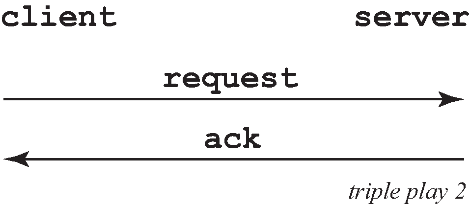
In the first scenario, the DHCP discover triggers an authentication message to RADIUS and the DHCP request also triggers RADIUS authentication. The previous reply is cached for 10 seconds, the second DHCP packet does not result in a RADIUS request.
In the second scenario, the DHCP request triggers an authentication message to RADIUS.
If the optional subscriber management authentication policy re-authentication command is enabled, DHCP authentication is performed at every DHCP lease renew request. Only dynamic DHCP sessions are subject to remote authentication. Statically provisioned hosts are not authenticated.
RADIUS authentication extensions
This section describes an extension to RADIUS functionality in the subscriber management context. As part of subscriber host authentication, RADIUS can respond with access-response message, which, in the case of an accept, can include several RADIUS attributes (standard and vendor-specific) that allow correct provisioning of a given subscriber-host.
Change-of-Authorization (CoA) messages as defined by RFC 3576, Dynamic Authorization Extensions to Remote Authentication Dial In User Service (RADIUS), are supported. The goal of CoA messages is to provide a mechanism for ‟mid-session change” support through RADIUS.
Triple Play network with RADIUS authentication
Triple Play aggregation network with RADIUS-based DHCP host authentication shows a flow of RADIUS authentication of DHCP hosts in the Triple Play aggregation environment. Besides granting the authentication of specified DHCP host, the RADIUS server can include RADIUS attributes (standard or Vendor-Specific Attributes (VSAs)) which are then used by the network element to provision objects related to a specified DHCP host.
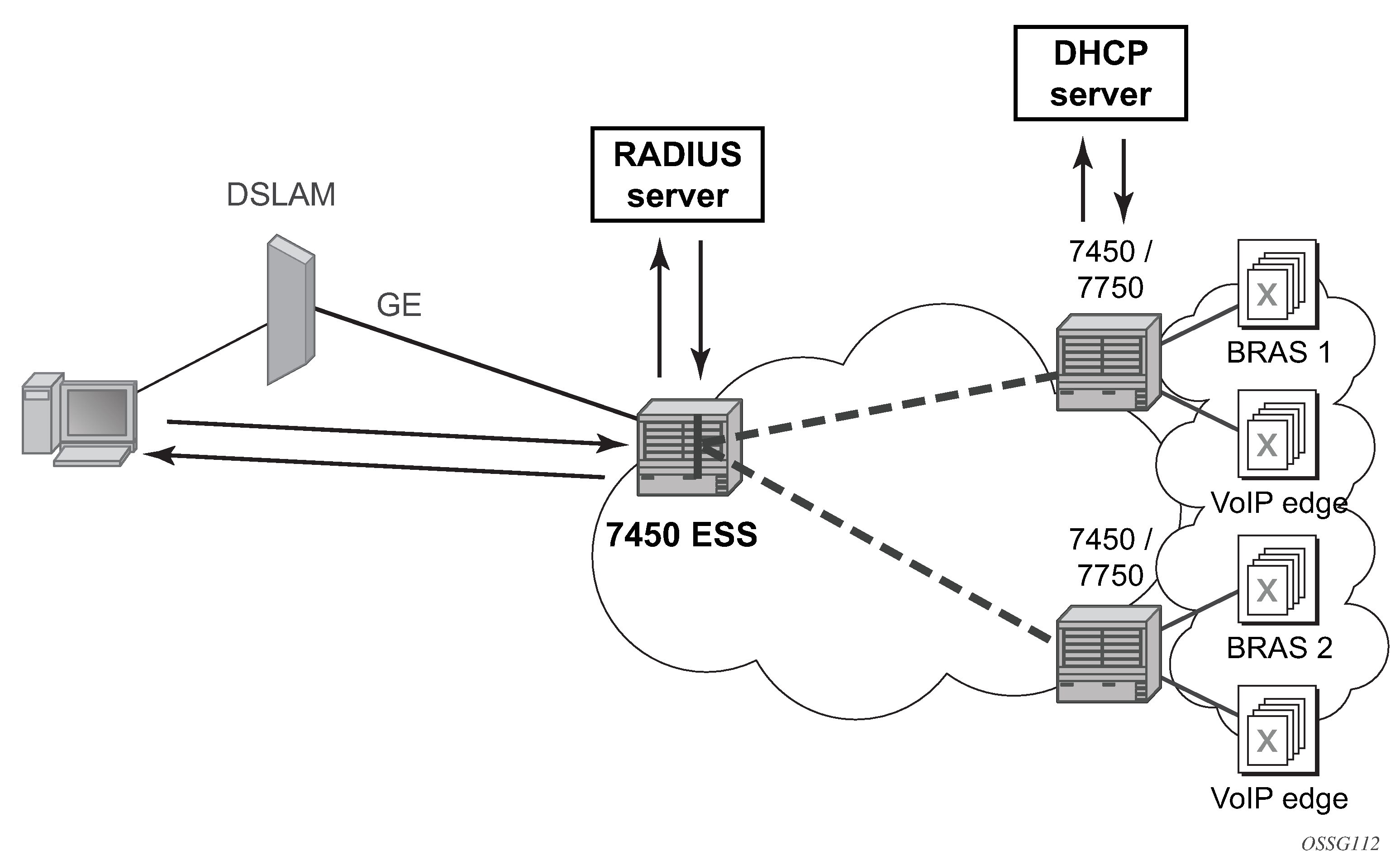
RADIUS is a distributed client/server concept that is used to protect networks against unauthorized access. In the context of the router’s subscriber management in TPSDA, the RADIUS client running on nodes sends authentication requests to the SSC.
RADIUS can be used to perform three distinct services:
Authentication determines whether a specific subscriber-host can access a specific service.
Authorization associates connection attributes or characteristics with a specific subscriber host.
Accounting tracks service use by individual subscribers.
The RADIUS protocol uses ‟attributes” to describe specific authentication, authorization, and accounting elements in a user profile (which are stored on the RADIUS server). RADIUS messages contain RADIUS attributes to communicate information between network elements running a RADIUS client and a RADIUS server.
RADIUS divides attributes into two groups, standard attributes and Vendor-Specific Attributes (VSAs). VSA is a concept allowing conveying vendor-specific configuration information in a RADIUS messages, as discussed in RFC 2865, Remote Authentication Dial In User Service (RADIUS). It is up to the vendor to specify the exact format of the VSAs.
Nokia-specific VSAs are identified by vendor-id 6527.
RADIUS authorization extensions
The following sections define different functional extensions and list relevant RADIUS attributes.
Basic Provisioning of Authentication Extensions
To comply with RFC 4679, DSL Forum Vendor-Specific RADIUS Attributes, the software includes the following attributes in the authentication-request message:
agent-circuit-id (as defined by DSL forum)
agent-remote-id (as defined by DSL forum)
The following attributes can also be included if configured and provided by downstream equipment:
actual-data-rate-upstream
actual-data-rate-downstream
minimum-data-rate-upstream
minimum-data-rate-downstream
access-loop-encapsulation
When the node is configured to insert (or replace) Option 82, the above mentioned attributes do have the content after this operation has been performed by the software.
In addition, the following standard RADIUS attributes are included in authentication request messages (subject to configuration):
NAS-identifier — string containing system-name
NAS-port-id
NAS-port-type — Values: 32 (null encap), 33 (dot1q), 34 (qinq), 15 (DHCP hosts), specified value (0 — 255)
MAC-address (Nokia VSA 27)
dhcp-vendor-class-id (Nokia VSA 36)
calling-station-id
These are only be included in the access-request if they have been configured.
To provide the possibility to push new policies for currently active subscribers, the routers support commands to force re-authentication of the specified subscriber-host. After issuing such a command, the router sends a DHCP FORCERENEW packet, which causes the subscriber to renew its lease (provided it supports force-renew). The DHCP request and ACK are then authenticated and processed by the routers as they would be during a normal DHCP renew.
Calling station ID
A calling-station-id can be configured at SAP level and can be included in the RADIUS authentication and accounting messages. This attribute is used in legacy BRAS to identify the user (typically phone number used for RAS connection). In the broadband networks this was replaced by circuit-id in Option 82. However, the Option 82 format is highly dependent on access-node (AN) vendor, which makes interpretation in management servers (such as RADIUS) difficult. Some operators use the calling-station-id attribute as an attribute indicating the way the circuit-id should be interpreted. The calling-station-id attribute can be configured as a string which is be configured on the SAP. It can also be configured to use the sap-id, remote-id, or mac-address.
Subscriber session timeout
To limit the lifetime of a PPP session or DHCPv4 host to a fixed time interval, a timeout can be specified from RADIUS. By default, a PPP session or DHCPv4 host has no session timeout (infinite).
For PPP sessions, a session-timeout can be configured in the ppp-policy. A RADIUS specified session-timeout overrides the CLI configured value.
    subscriber-mgmt
        ppp-policy "ppp-policy-1" create
            session-timeout 86400
        exit
    exit
When the session timeout expires a PPP session is terminated and a DHCPv4 host deleted. For a DHCPv4 host, a DHCP release message is also sent to the server.
The following two attributes can be used in RADIUS Access-Accept and CoA messages to limit the PPP session or DHCPv4 host session time (Subscriber session timeout):
| Attribute ID | Attribute name | Type | Limits | Purpose and format |
|---|---|---|---|---|
27 |
Session-Timeout |
integer |
2147483647 seconds |
0 = infinite (no session-timeout) (1 to 2147483647) in seconds For example: Session-Timeout = 3600 |
26-6527-160 |
Alc-Relative-Session-Timeout |
integer |
[0 to 2147483647] seconds |
0 = infinite (no session-timeout) (1 to 2147483647) in seconds For example: Alc-Relative-Session-Timeout = 3600 |
When specified in a RADIUS Access-Accept message, both attributes specify an absolute value for session timeout. When specified in a RADIUS CoA message, attribute [26-6527-160] Alc-Relative-Session-Timeout specifies a relative session timeout value in addition to the current session time while attribute [27] Session-Timeout specifies an absolute session timeout value. If the current session time is greater than the received Session-Timeout, a CoA NAK is sent with error cause ‟Invalid Attribute Value (407)”.
Only one of the above attributes to specify a session timeout can be present in a single RADIUS message. An event is raised when both are specified in a single message.
The output of the show service id service-id ppp session detail command contains following fields related to session timeout for PPP sessions:
Up Time: the PPP session uptime
Session Time Left: the remaining time before the session is terminated
RADIUS Session-TO: the RADIUS received session timeout value.
The output of the show service id service-id dhcp lease-state detail command contains following fields related to session timeout for DHCPv4 hosts:
Up Time
the DHCPv4 host uptime
Remaining Lease Time
the remaining time before the lease expires in the DHCP server. The client should renew its lease before this time.
Remaining SessionTime
the remaining time before the DHCPv4 host is deleted
Session-Timeout
the DHCPv4 host is deleted when its uptime reaches the Session-Timeout value.
Lease-Time
the lease time specified by the DHCPv4 server
Domain name in authentication
In many networks, the username has specific meaning with respect to the domain (ISP) where the user should be authenticated. To identify the user correctly, the username in an authentication-request message should contain a domain name. The domain name can be derived from different places. In PPPoE authentication the domain name is provided by the PPPoE client with the username used in PAP or CHAP authentication. For DHCP hosts similar functionality is implemented by a ‟pre-authentication” lookup in a local user database before performing the RADIUS request.
For example, it can be derived from option60 which contains the vendor-specific string identifying the ISP the set-box has been commissioned by.
To append a domain name to a DHCP host, the following configuration steps should be taken:
Under the (group or IP) interface of the service, a local user database should be configured in the DHCP node and no authentication policy should be configured.
In the local user database, there should be a host entry containing both the domain name to be appended and an authentication policy that should be used for RADIUS authentication of the host. The host entry should contain no other information needed for setting up the host (IP address, ESM string), otherwise the DHCP request is dropped.
In the authentication policy, the user-name-format command should contain the parameter append domain-name.
RADIUS reply message for PPPoE PAP/CHAP
The string returned in a [18] Reply-Message attribute in a RADIUS Access-Accept is passed to the PPPoE client in the CHAP Success or PAP Authentication-Ack message.
The string returned in a [18] Reply-Message attribute in a RADIUS Access-Reject is passed to the PPPoE client in the CHAP Failure or PAP Authentication-Nak message.
When no [18] Reply-Message attribute is available, the SR OS default messages are used instead: ‟CHAP authentication success” or ‟CHAP authentication failure” for CHAP and ‟Login ok” or ‟Login incorrect” for PAP.
SHCV policy
SHCV policies are used to control subscriber host connectivity verification which verifies the host connectivity to the BNG. There are two types of SHCV: periodic and event triggered. Before Release 13.0R4, some event triggered SHCV relied on the reference timer set by the host-connectivity-verify under the group interface while others had hard-coded values. Release 13.0R4 introduced the SHCV policy that allows individual configuration of trigger SHCV timers and periodic SHCV timers depending on the application.
Under the group-interface, the host-connectivity-verify configuration was used as a reference timer for some event triggered SHCV while other used hard-coded values. The SHCV policy separated out every type of SHCV and allows each type to have their individual configurable timer values. Furthermore, individual SHCV trigger types can be shut down. The SHCV policy can be applied to one or more group interfaces and can be configured differently for IPv4 vs. IPv6 hosts. There are various types of triggered SHCV:
-
ip-conflict
This SHCV is sent when a SAP detects that there is a IP address or prefix conflict on the SAP.
-
host-limit-exceeded
Sent when a subscriber has exceeded a configured host or session limit. Host limits are set in the sla-profile host-limits and in the sub-profile host-limits. Session limits are set in the group-interface ipoe-session sap-session-limit and session-limit, in the sla-profile session-limits and in the sub-profile session-limits contexts.
-
inactivity
The category-map configured under sla-profile can trigger an SHCV when the subscriber host becomes idle.
-
mobility
Intended for mobility applications such as Wi-Fi. When a subscriber moves between SAPs and requests for the same IP address, a triggered SHCV is sent to verify if the old host is still connected before removing the old host entry.
-
mac-learning
For IP-only static-host MAC learning. The trigger SHCV is sent to learn the subscriber MAC when a no shutdown command is executed on the CLI for the static host.
Some SHCVs are triggered based on a host’s DHCP messages. These DHCP messages are not buffered. The SHCV is used only to perform a verification check on an old host to verify if the host is still connected to the BNG. Therefore, the BNG still requires the new hosts to retransmit their DHCP messages after the SHCV removes the disconnected host.
radius-server-policy retry attempt overview
This feature maximizes the use of the remaining healthy RADIUS servers for subscriber authentication and accounting. After the hold-down time expires, a single RADIUS message is used to determine the status of the RADIUS server. If the server remains unresponsive after waiting for a single timeout interval (without any retries), then it is placed back into the hold-down state. If the RADIUS server responds, then it is used for subscriber authentication and accounting with the rest of the healthy servers.
AAA RADIUS server operation status
The different operating states of a RADIUS server are shown in RADIUS server operating states. When a RADIUS server is first provisioned into the AAA using the radius-server-policy command, the operating state is ‟unknown”. This state indicates that the RADIUS server has yet to receive a RADIUS request message. To send a request message, the radius-server-policy command provides three different access algorithms: direct, round-robin, and hash. With the direct algorithm, request messages are always sent to the in-service RADIUS server with the lowest configured server index. With the round-robin algorithm, the RADIUS requests are load-balanced in a round-robin manner. The hash algorithm offers a load-balanced alternative; the 7750 SR generates a hash-key based on the subscriber information, and the RADIUS request is then sent to a server based on the hash key. The hash method differs from the round-robin method in that, under normal working conditions, RADIUS requests from a particular subscriber are always forwarded to the same RADIUS server. When a server replies to a RADIUS request, it transitions from the operational state of ‟unknown” to ‟in-service”. A server may transition from ‟unknown” to ‟out-of-service” if the server fails to respond to the initial RADIUS message.
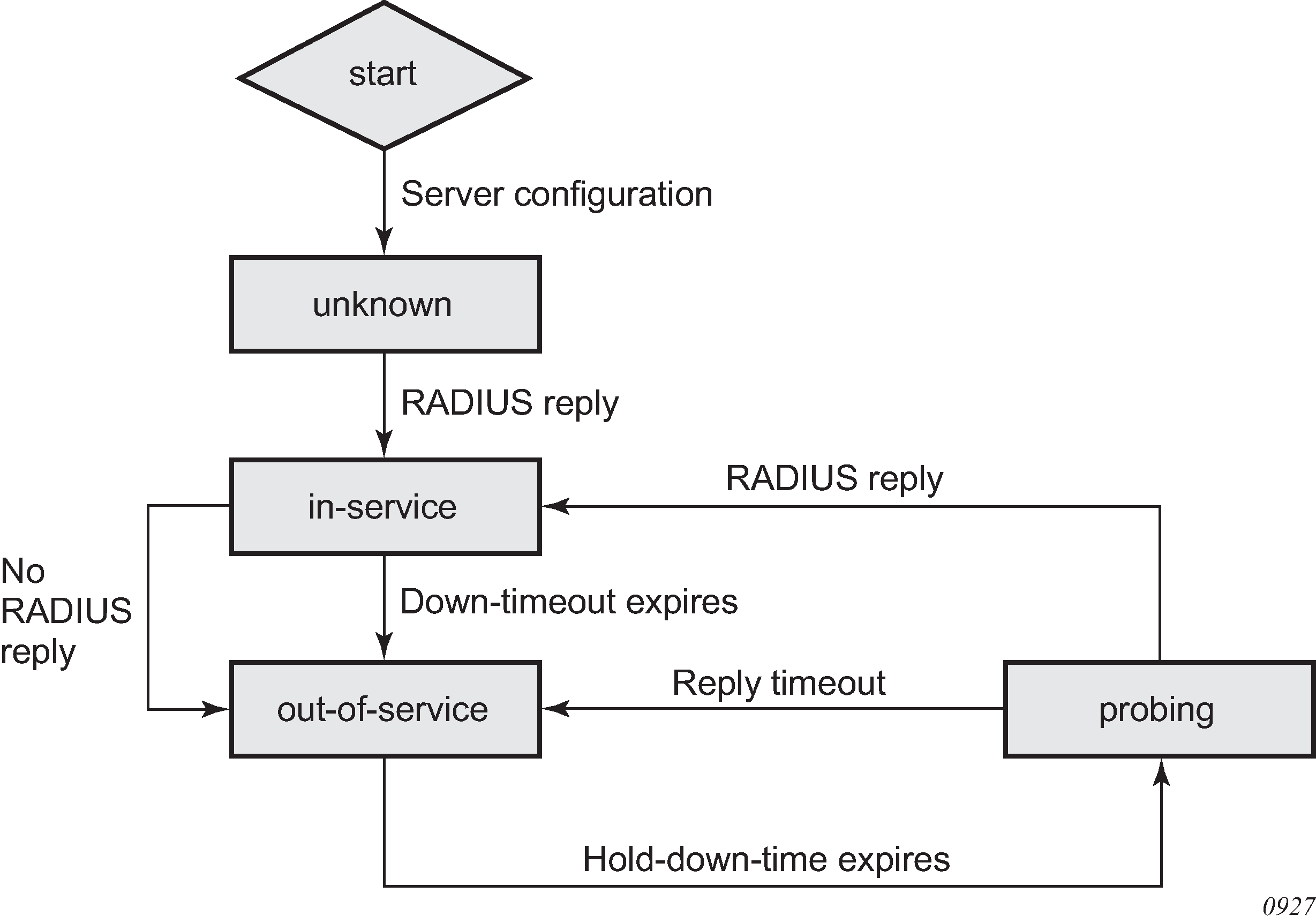
A RADIUS server is declared ‟out-of-service” when the down-timeout timer expires. The router starts the down-timeout timer when an access-request is sent. The timer only resets to ‟0” when a reply is received from the RADIUS server. This means that the timer can be reset to ‟0” if a reply message is received for another subscriber. For example, the RADIUS server may miss a message but stay ‟in-service” if the server responds to another access request from a different subscriber or from a retry of the same subscriber, if the reply is received within the down-timeout interval.
The down-timeout default value is the timeout value multiplied by the number of retry attempts. The timeout value is the time that the router waits for the RADIUS server to reply, and the retry value is the number of attempts the 7750 SR makes to contact the RADIUS server. If the RADIUS server remains unresponsive, the timer continues to increment until it reaches the configured down-timeout value and the server is declared ‟out-of-service”.
For RADIUS servers that do not respond to all RADIUS requests, a test user account can be optionally set up to periodically send RADIUS request messages to keep the server in service. Typically, a RADIUS server should always respond to all access requests. However, creating a test user account for periodic keep-alive may place an unnecessary load on the processor and may lower the overall scale of the router.
At the start of the out-of-service state, a down-timeout timer starts. The timer holds down the RADIUS server and prevents it from operating; no RADIUS messages are sent to an out-of-service server. This is beneficial for the following reasons.
The server may be unresponsive because of excessive RADIUS message requests; holding it down allows the server to recover.
Holding down an unresponsive server allows other healthy RADIUS servers to service new requests promptly.
After the hold-down-time timer expires, the server enters into the ‟probing” state. There must be multiple RADIUS servers and at least one healthy server for the server to enter the probing state. Probing is always performed by the test user account; actual subscriber requests are never used during probing. If no test user account exists, an actual subscriber request is used to perform the probe. There are no retry attempts; only a single RADIUS message is used to probe a RADIUS server. If the RADIUS server responds, it is declared ‟in-service” immediately. If the RADIUS server fails to respond within the timeout value, it is declared ‟out-of-service” again and the hold-down-time timer restarts. Subscriber RADIUS messages used for probing are not cached, and if the server fails to respond, the subscriber is required to send the RADIUS message again by sending an address request; for example, DHCP, PPP, or Stateless Address Auto-Configuration (SLAAC) or by performing a data-trigger.
AAA RADIUS accounting server stickiness
Stickiness applies to the following subscriber RADIUS accounting sessions: start, interim, and stop. By default, the subscriber sticks with the server that served its last accounting message. For example, if server 1 served the subscriber an accounting start message, then the subsequent interim messages and stop message from the same subscriber is sent to server 1. If server 1 is out of service, server 2 is used for the subsequent interim and stop messages. When server 1 recovers, the interim and stop messages sticks with server 2. The RADIUS accounting messages are always be forwarded to the server that serviced the subscriber’s last accounting message.
Typically, when using the direct access algorithm, the primary server (lowest configured server index) serves all RADIUS request messages. The other RADIUS servers are used for backup purposes only and may be using a lighter-weight processor. Therefore, it is best to revert to the primary server as soon as it is restored. This can be accomplished by disabling stickiness in direct mode; the RADIUS accounting messages are forwarded to the primary server after it is restored.
In a round-robin algorithm, while each subscriber session is assigned to a different server in round-robin order, a particular subscriber sticks with a server for the entire accounting session. Disabling stickiness sends a subscriber’s RADIUS accounting messages to the list of configured RADIUS servers in a round-robin order.
AAA RADIUS authentication fallback action
The fallback action comes into effect when connectivity to all RADIUS servers is lost. The operating state of the RADIUS servers changes to either ‟out-of-service” or ‟probing”. There are two configurable fallback actions: accept or user-db. An accept action without force-probing automatically accepts all authentication requests from all subscribers. A user-db action without force-probing uses the local-user-db for subscriber authentication.
Both accept and user-db can be combined with the force-probing command. Force-probing forces the out-of-service server to transition to the probing state immediately, bypassing the hold-down-time timer. Force-probing is a mechanism to promptly restore connectivity to a RADIUS server. A test user is not used to perform a force probe; only actual subscriber authentication is used to test the operating state of the RADIUS server. Probing only occurs when a server is out of service. If all servers are in the probing state, all new incoming authentication requests follow the fallback action immediately.
When probing with an actual subscriber authentication, the 7750 SR only waits for a reply for one timeout interval without any retries. During the wait, the server is in a probing state and no other subscribers are used to probe this server. The subscriber authentication request is not cached when used for probing. Therefore, to trigger authentication again, the subscriber is required to authenticate again with an address request or a data-trigger packet.
AAA test user account
A test user account is used in the rare case where a RADIUS server ignores RADIUS messages as mentioned in the AAA RADIUS server operation status section. Consequently, when messages are ignored, the router places the RADIUS server out of service. The test user account can keep a RADIUS server in service by periodically sending RADIUS requests to the server. The RADIUS server, while randomly ignoring other subscriber RADIUS requests, must respond to the test user requests. A RADIUS server is in service if it replies to RADIUS messages before the down-timeout timer expires. The default down-timeout default value is the timeout value multiplied by the retry value, but it is also configurable. The test user account has a configurable interval value, and it is recommended that this value be configured to be less than the down-timeout value for it to be useful. The test user account only applies to RADIUS authentication.
Typically, a RADIUS server always responds to all RADIUS requests, and therefore it is not recommended that a test user account be used unless it is absolutely necessary for specific types of servers. The test user account creates extra load for the processor and can affect scaling. The test user account can be used with a Python script (for example, adding additional attributes to the test user account during an access-request operation).
Troubleshooting the RADIUS server
The tools>perform>security>authentication-server-check command can be used to troubleshoot a RADIUS server by checking the connectivity and functional status of a RADIUS server for subscriber management operations. The command keyword debug can be specified to view more information about the access request. All VSAs sent and received from the RADIUS server, the hex dump, and all other debug information can be shown without the need to turn on system-wide debugging.
Additional attributes in an Access-Request message can be specified in an attribute file referenced with the command keyword attr-from-file file-url. Each attribute must be specified on a separate line in the text file in the following format shown in authentication-server-check attribute file format .
| Attribute file format | Description |
|---|---|
<type> = <value> |
Standard attribute |
<vendor>,<type> = <value> |
Vendor Specific Attribute |
e,<type>,<ext-type> = <value> |
Extended type attribute (RFC 6929) |
evs, <type>, <vendor>, <vendortype> = <value> |
Extended Vendor Specific attribute (RFC 6929) |
le,<type>,<ext-type> = <value> |
Long Extended type attribute (RFC6929) |
evs, <type>, <vendor>, <vendortype> = <value> |
Long Extended Vendor Specific attribute (RFC 6929) |
Provisioning of Enhanced Subscriber Management (ESM) objects
In the ESM concept on network elements, a subscriber host is described by the following aspects:
subscriber-id-string
subscriber-profile-string
sla-profile-string
ancp-string
intermediate-destination-identifier-string
application-profile-string
This information is typically extracted from DHCP-ACK message using a Python script, and is used to provision subscriber-specific resources such as queues and filter entries. As an alternative to extracting this information from DHCP-ACK packet, provisioning from RADIUS server is supported.
As a part of this feature, the following VSAs have been defined:
alc-subscriber-id-string
Contains a string which is interpreted as a subscriber-id.
alc-subscriber-profile-string
Contains a string which is interpreted as a subscriber profile
alc-sla-profile-string
Contains string which is interpreted as an SLA profile.
alc-ancp-string
Contains string which is interpreted as an ANCP string.
alc-int-dest-id-string
Contains a string which is interpreted as an intermediate destination ID
alc-app-profile-string
Contains a string which is interpreted as an application profile
Note that these strings can be changed in a CoA request.
When RADIUS authentication response messages contain the above VSAs, the information is used during processing of DHCP-ACK message as an input for the configuration of subscriber-host parameters, such as QoS and filter entries.
If ESM is not enabled on a specified SAP, information in the VSAs is ignored.
If ESM is enabled and the RADIUS response does not include all ESM-related VSAs (an ANCP string is not considered as a part of ESM attributes), only the subscriber-id is mandatory (the other ESM-related VSAs are not included). The remaining ESM information (sub-profile, sla-profile) is extracted from DHCP-ACK message according to normal flow (Python script, and so on).
If the profiles are missing from RADIUS, they are not extracted from the DHCP data with Python to prevent inconsistent information. Instead, the data reverts to the configured default values.
However, if the above case, a missing subscriber ID causes the DHCP request to be dropped. The DHCP server is not queried in that case.
When no DHCP server is configured, DHCP-discover/request messages are discarded.
Provisioning IP configuration of the host
The other aspect of subscriber-host authorization is providing IP configuration (ip-address, subnet-mask, default gateway and dns) through RADIUS directory instead of using centralized DHCP server. In this case, the node receiving following RADIUS attributes assumes the role of DHCP server in conversation with the client and provide the IP configuration received from RADIUS server.
These attributes are accepted only if the system is explicitly configured to perform DHCP server functionality on a specific interface.
The following RADIUS attributes are accepted from authentication-response messages:
framed-ip-address
The IP address to be configured for the subscriber-host
framed-ip-netmask
The IP network to be configured for the subscriber host If RADIUS does not return a netmask, the DHCP request is dropped
framed-pool
The pool on a local DHCP server from which a DHCP-provided IP address should be selected
alc-default-router
The address of the default gateway to be configured on the DHCP client
alc-primary-dns
The DNS address to be provided in DHCP configuration.
Juniper VSA for primary DNS
Redback VSA for primary DNS
alc-secondary-dns
Juniper VSA for secondary DNS
Redback VSA for secondary DNS
alc-lease-time
Defines the lease time
session-timeout — Defines the lease time in absence of the alc-lease-time attribute
NetBIOS
alc-primary-nbns
alc-secondary-nbns
RADIUS-based authentication in wholesale environment
To support VRF selection, alc-retail-serv-id indicates the service-id of the required retail VPRN service configured on the system
- Alc-Retail-Serv-Name
Indicates the service name of the required retail VPRN service configured on the system.
- Alc-Retail-Serv-Name
Indicates the service name of the required retail VPRN service configured on the system.
Alc-Retail-Serv-Id takes precedence over Alc-Retail-Serv-Name if both are specified.
Change of authorization and disconnect-request
In a typical RADIUS environment, the network element serves as a RADIUS client, which means the messages are originated by a routers. In some cases, such as mid-session changes, it is desirable that the RADIUS server initiates a CoA request to impose a change in policies applicable to the subscriber, as defined by RFC 3576.
To configure a RADIUS server to accept CoA and Disconnect Messages is achieved in one of the following ways:
Configure up to 64 RADIUS CoA servers per routing instance:
    config>router>radius-server#
    config>service>vprn>radius-server#
     server "coa-1" address 10.1.1.1 secret <shared-secret> hash2 create
         accept-coa
     exit
This is the preferred method.
Configure up to 16 RADIUS CoA servers per authentication policy.
    config>subscr-mgmt>auth-plcy#
     accept-authorization-change
The UDP port for CoA and Disconnect Messages is configurable per system with the command:
    config>aaa#
    radius-coa-port {1647|1700|1812|3799}
There is a priority in the functions that can be performed by CoA. The first matching one is performed:
If the CoA packet contains a Force-Renew attribute, the subscriber gets a FORCERENEW DHCP packet. This function is not supported for PPPoE or ARP hosts.
If the CoA packet contains a create-host attribute, a new lease-state is created. Only DHCP lease-states can be created by a CoA message. PPPoE sessions and ARP hosts cannot be created.
Otherwise, the ESM strings are updated.
There are several reasons for using RADIUS initiated CoA messages:
Changing ESM attributes (SLA or subscriber profiles) or queues/policers/schedulers rates of the specific subscriber host. CoA messages containing the identification of the specified subscriber-host along with new ESM attributes.
Changing (or triggering the change) of IP configuration of the specified subscriber-host. CoA messages containing the identification of the specified subscriber-host along with VSA indicating request of FORCERENEW generation.
Configuring new subscriber-host. CoA messages containing the full configuration for the specific host.
If the changes to ESM attributes are required, the RADIUS server sends CoA messages to the network element requesting the change in attributes included in the CoA request:
attributes to identify a single or multiple subscriber hosts: NAS-Port-Id + IP address/prefix or Acct-Session-Id or Alc-Subsc-ID-Str
Nas-Port-Id attribute + single IP address/prefix attribute:
Framed-IP-Address
Alc-Ipv6-Address
Framed-Ipv6-Prefix
Delegated-Ipv6-Prefix
Alc-Client-Hardware-Addr (Required for private-retail subnet. For more information, see the 7450 ESS, 7750 SR, and VSR RADIUS Attributes Reference Guide.)
Acct-Session-Id (number format)
Alc-Subsc-ID-Str
User-Name (Possible to use in combination with the following. For more information, see the 7450 ESS, 7750 SR, and VSR RADIUS Attributes Reference Guide.)
Framed-Ip-Address
Alc-Ipv6-Address
Framed-Ipv6-Prefix
Delegated-Ipv6-Prefix
Alc-Client-Hardware-Addr
alc-subscriber-profile-string
alc-sla-profile-string
alc-ancp-string
alc-app-profile-string
alc-int-dest-id-string
alc-subscriber-id-string
alc-subscriber-qos-override
Note: If the subscriber-id-string is changed while the ANCP string is explicitly set, the ANCP-string must be changed simultaneously. When changing the alc-subscriber-id-string, the lease state is temporarily duplicated, causing two identical ANCP-strings to be in the system at the same time. This is not allowed.
As a reaction to such message, the router changes the ESM settings applicable to the specified host.
If changes to the IP configuration (including the VRF-ID in the case of wholesaling) of the specified host are needed, the RADIUS server may send a CoA message containing VSA indicating request for FORCERENEW generation:
attributes to identify a single or multiple subscriber hosts: ‟NAS-Port-Id + IP address/prefix” or ‟Acct-Session-Id” or ‟Alc-Subsc-ID-Str” or ‟user-name”:
Nas-Port-Id attribute + single IP address/prefix attribute:
Framed-IP-Address
Alc-Ipv6-Address
Framed-Ipv6-Prefix
Delegated-Ipv6-Prefix
Acct-Session-Id (number format)
Alc-Subsc-ID-Str
User-Name
alc-force-renew
alc-force-nak
As a reaction to a message, router generates a DHCP FORCERENEW message for the specified subscriber host. Consequently, during the re-authentication, new configuration parameters can be populated based on attributes included in Authentication-response message. The force-NAK attribute has the same function as the Force-Renew attribute, but causes the BNG to reply with a NAK to the next DHCP renew. This invalidates the lease state on the BNG and force the client to completely recreate its lease, making it possible to update parameters that cannot be updated through normal CoA messages, such as IP address or address pool.
If the configuration of the new subscriber-host is required, RADIUS server sends a CoA message containing VSA request new host generation along with VSAs specifying all required parameters.
alc-create-host
alc-subscriber-id-string
This attribute is mandatory in case ESM is enabled, and optional for new subscriber host creation otherwise.
NAS-port-id
This attribute indicates the SAP where the host should be created.
framed-ip-address
the framed IP address
alc-client-hw-address
A string in the xx:xx:xx:xx:xx:xx format. This attribute is mandatory for new subscriber-host creation.
alc-lease-time
Specifies the lease time. If both session-timeout and alc-lease-time are not present, then a default lease time of 7 days is used.
session-timeout
Specifies the lease time in absence of the alc-lease-time attribute. If both session-timeout and alc-lease-time are not present, then a default lease time of 7 days is used.
alc-retail-svc-id
This is only used in case of wholesaling for selection of the retail service. Indicates the service-id of the required retail VPRN service configured on the system.
Optionally other VSAs describing a specified subscriber host. If the ESM is enabled, but the CoA message does not contain ESM attributes, the new host is not created.
After executing the requested action, the router element responds with an ACK or NAK message depending on the success/failure of the operation. In case of failure (and then, a NAK response), the element includes the error code in accordance with RFC 3576 definitions if an appropriate error code is available.
Supporting CoA messages has security risks as it essentially requires action to unsolicited messages from the RADIUS server. This can be primarily the case in an environment where RADIUS servers from multiple ISPs share the same aggregation network. To minimize the security risks, the following rules apply:
Support of CoA messages is disabled by default. They can be enabled on a per RADIUS server or authentication-policy basis.
When CoA is enabled, the node listens and react only to CoA messages received from RADIUS servers. In addition, CoA messages must be protected with the key corresponding to the specified RADIUS server. All other CoA messages are silently discarded.
In all cases (creation, modification, force-renew) subscriber host identification attributes are mandatory in the CoA request: ‟NAS-Port-Id + IP” or ‟Acct-Session-Id” or ‟Alc-Subsc-ID-Str” or ‟user-name”.
Nas-Port-Id + single IP address/prefix:
Nas-Port-Id
Framed-IP-Address
Alc-Ipv6-Address
Framed-Ipv6-Prefix
Delegated-Ipv6-Prefix
Alc-Client-Hardware-Addr (may be required for private retail subnet. For more information, see the RADIUS Attributes Reference Guide.)
Acct-Session-Id (number format)
Alc-Subsc-ID-Str
User-Name (Possible to use in combination with the following. For more information, see the 7450 ESS, 7750 SR, and VSR RADIUS Attributes Reference Guide.)
Framed-Ip-Address
Alc-Ipv6-Address
Framed-Ipv6-Prefix
Delegated-Ipv6-Prefix
Alc-Client-Hardware-Addr
When there are no subscriber host identification attributes present in the CoA, the message is NAK’d with corresponding error code.
Receiving CoA message with the same attributes as currently applicable to the specified host responds with an ACK message.
In case of dual homing (through SRRP), the RADIUS server should send CoA messages to both redundant nodes and this with all corresponding attributes (NAS-port-id with its local meaning to corresponding node).
In the case of change requests, the node which has the specified host active (active SAP or SAP associated with a group interface in SRRP master state) processes the RADIUS message and reply to RADIUS. The standby node always replies with a NAK.
In the case of create requests, the active node (the SAP described by NAS-port-id is active or associated with a group-interface in SRRP master state). Both nodes reply, but the standby NAKs the request.
The properties of an existing RADIUS-authenticated PPPoE session can be changed by sending a Change of Authorization (CoA) message from the RADIUS server. Processing of a CoA is done in the same way as for DHCP hosts, with the exception that only the ESM settings can be changed for a PPPoE session (the Force-Renew attribute is not supported for PPPoE sessions and a Create-Host CoA always generates a DHCP host).
For terminating PPPoE sessions from the RADIUS server, the disconnect-request message can be sent from the RADIUS server. This message triggers a shut down of the PPPoE session. The attributes needed to identify the PPPoE session are the same as for DHCP hosts.
Change of authorization using the tools command
A CoA can be triggered through the CLI by using a tools command that does not require a RADIUS authentication policy. The tools command can also be used to spoof a CoA from a configured server for purposes such as testing CoA python scripts. However, when spoofing the CoA from a RADIUS server, the configuration of a RADIUS authentication policy is required.
The tools command, tools>perform>subscriber-mgmt>coa, supports up to five different VSAs. If more than five VSAs are required, a file with more than five VSAs can be used for execution.
The tools command does not support lawful intercept attributes.
SNMP can also trigger the tools CoA command. However, SNMP cannot execute the command when it is referencing an on-board flash file. To execute from a file, the file must be non-local, such as using a URL specifying the location of the file on an FTP server.
Only one tools command, tools>perform>subscriber-mgmt>coa command can be performed at a time. The command must complete execution before processing a new one. If the tools command becomes unresponsive, CTRL-c can be used to break out of the CoA. In addition, a failsafe mechanism automatically terminates the tools command if it has not completed within a minute.
RADIUS-based accounting
When a router is configured to perform RADIUS-based accounting, at the creation of a subscriber-host, it generates an accounting-start packet describing the subscriber-host and sends it to the RADIUS accounting server. At the termination of the session, it generates an accounting-stop packet including accounting statistics for a specified host. The router can also be configured to send an interim-accounting message to provide updates for a subscriber-host.
The exact format of accounting messages, their types, and communication between client running on the routers and RADIUS accounting server is described in RFC 2866, RADIUS Accounting. The following describes a few specific configurations.
To identify a subscriber-host in accounting messages different RADIUS attributes can be included in the accounting-start, interim-accounting, and accounting-stop messages. The inclusion of the individual attributes is controlled by the following commands.
configure
    subscr-mgmt
        radius-accounting-policy <name>
            include-radius-attribute
                [no] acct-authentic
                [no] acct-delay-time
                [no] called-station-id
                [no] calling-station-id
                [no] circuit-id
                [no] delegated-ipv6-prefix
                [no] dhcp-vendor-class-id
                [no] framed-interface-id
                [no] framed-ip-addr
                [no] framed-ip-netmask
                [no] framed-ipv6-prefix
                [no] framed-route
                [no] framed-ipv6-route
                [no] ipv6-address
                [no] mac-address
                [no] nas-identifier
                [no] nas-port
                [no] nas-port-id
                [no] nas-port-type
                [no] nat-port-range
                [no] remote-id
                [no] sla-profile
                [no] sub-profile
                [no] subscriber-id
                [no] tunnel-server-attrs
                [no] user-name
                [no] wifi-rssi
                [no] alc-acct-triggered-reason
                [no] access-loop-options
                [no] all-authorized-session-addresses
                [no] detailed-acct-attributes
                [no] std-acct-attributes
                [no] v6-aggregate-stats
RADIUS volume accounting attributes are depending on the type of volume reporting and can be controlled with an include-radius-attribute CLI command. Multiple volume reporting types can be enabled simultaneously:
config
    subscr-mgmt
        radius-accounting-policy <name>
            include-radius-attribute
                [no] detailed-acct-attributes
                [no] std-acct-attributes
                [no] v6-aggregate-stats
where:
detailed-acct-attributes — Report detailed per queue and per policer counters using RADIUS VSAs (enabled by default). Each VSA contains a queue or policer ID followed by the stat-mode or 64 bit counter. The VSA’s included in the Accounting messages is function of the context (policer or queue, stat-mode, MDA type, and so on):
[26-6527-107] Alc-Acct-I-statmode
[26-6527-127] Alc-Acct-O-statmode
[26-6527-19] Alc-Acct-I-Inprof-Octets-64
[26-6527-20] Alc-Acct-I-Outprof-Octets-64
[26-6527-21] Alc-Acct-O-Inprof-Octets-64
[26-6527-22] Alc-Acct-O-Outprof-Octets-64
[26-6527-23] Alc-Acct-I-Inprof-Pkts-64
[26-6527-24] Alc-Acct-I-Outprof-Pkts-64
[26-6527-25] Alc-Acct-O-Inprof-Pkts-64
[26-6527-26] Alc-Acct-O-Outprof-Pkts-64
[26-6527-39] Alc-Acct-OC-O-Inprof-Octets-64
[26-6527-40] Alc-Acct-OC-O-Outprof-Octets-64
[26-6527-43] Alc-Acct-OC-O-Inprof-Pkts-64
[26-6527-44] Alc-Acct-OC-O-Outprof-Pkts-64
[26-6527-69] Alc-Acct-I-High-Octets-Drop_64
[26-6527-70] Alc-Acct-I-Low-Octets-Drop_64
[26-6527-71] Alc-Acct-I-High-Pack-Drop_64
[26-6527-72] Alc-Acct-I-Low-Pack-Drop_64
[26-6527-73] Alc-Acct-I-High-Octets-Offer_64
[26-6527-74] Alc-Acct-I-Low-Octets-Offer_64
[26-6527-75] Alc-Acct-I-High-Pack-Offer_64
[26-6527-76] Alc-Acct-I-Low-Pack-Offer_64
[26-6527-77] Alc-Acct-I-Unc-Octets-Offer_64
[26-6527-78] Alc-Acct-I-Unc-Pack-Offer_64
[26-6527-81] Alc-Acct-O-Inprof-Pack-Drop_64
[26-6527-82] Alc-Acct-O-Outprof-Pack-Drop_64
[26-6527-83] Alc-Acct-O-Inprof-Octs-Drop_64
[26-6527-84] Alc-Acct-O-Outprof-Octs-Drop_64
[26-6527-91] Alc-Acct-OC-O-Inpr-Pack-Drop_64
[26-6527-92] Alc-Acct-OC-O-Outpr-Pack-Drop_64
[26-6527-93] Alc-Acct-OC-O-Inpr-Octs-Drop_64
[26-6527-94] Alc-Acct-OC-O-Outpr-Octs-Drop_64
[26-6527-108] Alc-Acct-I-Hiprio-Octets_64
[26-6527-109] Alc-Acct-I-Lowprio-Octets_64
[26-6527-110] Alc-Acct-O-Hiprio-Octets_64
[26-6527-111] Alc-Acct-O-Lowprio-Octets_64
[26-6527-112] Alc-Acct-I-Hiprio-Packets_64
[26-6527-113] Alc-Acct-I-Lowprio-Packets_64
[26-6527-114] Alc-Acct-O-Hiprio-Packets_64
[26-6527-115] Alc-Acct-O-Lowprio-Packets_64
[26-6527-116] Alc-Acct-I-All-Octets_64
[26-6527-117] Alc-Acct-O-All-Octets_64
[26-6527-118] Alc-Acct-I-All-Packets_64
[26-6527-119] Alc-Acct-O-All-Packets_64
std-acct-attributes
Report IPv4 and IPv6 aggregated forwarded counters using standard RADIUS attributes (disabled by default):
[42] Acct-Input-Octets
[43] Acct-Output-Octets
[47] Acct-Input-Packets
[48] Acct-Output-Packets
[52] Acct-Input-Gigawords
[53] Acct-Output-Gigawords
v6-aggregate-stats
Report IPv6 aggregated forwarded counters of queues and policers in stat-mode v4-v6 using RADIUS VSAs (disabled by default):
[26-6527-194] Alc-IPv6-Acct-Input-Packets
[26-6527-195] Alc-IPv6-Acct-Input-Octets
[26-6527-196] Alc-IPv6-Acct-Input-GigaWords
[26-6527-197] Alc-IPv6-Acct-Output-Packets
[26-6527-198] Alc-IPv6-Acct-Output-Octets
[26-6527-199] Alc-IPv6-Acct-Output-Gigawords
In addition to accounting-start, interim-accounting, and accounting-stop messages, a RADIUS client on a routers also sends accounting-on and accounting-off messages. An accounting-on message is sent when a specific RADIUS accounting policy is applied to a specified subscriber profile, or the first server is defined in the context of an already applied policy. The following attributes included are in these messages:
NAS-identifier
alc-subscriber-profile-string
Accounting-session-id
Event-timestamp
Accounting-off messages are sent at following events:
An accounting policy has been removed from a sub-profile.
The last RADIUS accounting server has been removed from an already applied accounting policy.
These messages contain following attributes:
NAS-identifier
alc-subscriber-profile-string
Accounting-session-id
Accounting-terminate-cause
Event-timestamp
In case of dual homing, both nodes send RADIUS accounting messages for the host, with all attributes as it is locally configured. The RADIUS log files on both boxes need to be parsed to get aggregate accounting data for the specified subscriber host regardless the node used for forwarding.
For RADIUS-based accounting, a custom record can be defined to refine the data that is sent to the RADIUS server. See the ‟Configuring an Accounting Custom Record” in the 7450 ESS, 7750 SR, 7950 XRS, and VSR System Management Guide for further information.
RADIUS accounting terminating cause
The VSA acct-terminate-cause attribute provides some termination information. Two additional attributes: [VSA 227] alc-error-message and [VSA 226] alc-error-code provide more information in both string and numeric format about the terminating cause of the subscriber session. The full list of error messages and their corresponding error codes may be viewed using the command tools>dump>aaa> radius-acct-terminate-cause.
If required, python can alter the content of both VSAs. The following is a python script example where the error codes are remapped from 123 to 8 and from 124 to 17:
import alc
import struct

ALU            = 6527
TERM_CAUSE     = 49
ALC_ERROR_CODE = 226

if (alc.radius.attributes.isSet(TERM_CAUSE) and
    alc.radius.attributes.isVSASet(ALU, ALC_ERROR_CODE)):

    error_code = alc.radius.attributes.getVSA(ALU, ALC_ERROR_CODE)
    error_code = struct.unpack('!i', error_code)[0]

    term_cause  = alc.radius.attributes.get(TERM_CAUSE)
    term_cause = struct.unpack('!i', term_cause)[0]

    #print "error code = ", error_code
    #print "term cause = ", term_cause

    # table with mapping from alc-error-code to the standard terminate cause
    # if no mapping is found, no transformation is performed
    error_map = {
        123 : 8,
        124 : 17
    }

    new_term_cause = error_map.get(error_code, term_cause)
    #print "new term_cause = ", new_term_cause

    alc.radius.attributes.set(TERM_CAUSE, struct.pack('!I', new_term_cause))
Accounting modes of operation
This section is applicable to the 7750 SR or the 7450 ESS. There are three basic accounting models:
Per queue-instance
Per Host
Per Session
Each of the basic models can optionally be enabled to send interim-updates. Inclusion/exclusion of interim-updates depends on whether volume based (start/interim-updates/stop) or time-based (start/stop) accounting is required.
The difference between the three basic accounting models is in its core related to the processing of the acc-session-id for each model. The differences are related to:
acct-session-id generation within each model
outcome in response to the CoA action relative to the targeted acct-session-id
The counters for volume-based accounting are collected from queues or policers that are instantiated per SLA profile instance (SPI). This is true regardless of which model of accounting (or combination of models) is deployed. Within the accounting context, the SPI equates to queue-instance.
The following table summarizes the key differences between various accounting modes of operation that are supported. Interim-updates for each individual mode can be enabled or disabled through configuration (keyword as an extension to the commands that enable three basic modes of accounting). This is denoted by the IU-Config keyword under the ‛I-U’ column in the table. The table also shows that any two combinations of the three basic models (including their variants for volume and time- based accounting) can be enabled simultaneously.
| Accounting mode | Accounting entity | START | I-U | STOP | Acct-session-id | Acct-multi-session-id |
|---|---|---|---|---|---|---|
queue-instance-accounting |
queue-instance |
X |
IU-config |
X |
X |
|
session |
||||||
host |
||||||
session-accounting |
queue-instance |
|||||
session |
X |
IU-config |
X |
X |
queue-instance |
|
host |
||||||
host-accounting |
queue-instance |
|||||
session |
||||||
host |
X |
IU-config |
X |
X |
queue-instance |
|
queue-instance-accounting + host-accounting |
queue-instance |
X |
IU-config |
X |
X |
queue-instance |
session |
||||||
host |
X |
IU-config |
X |
X |
queue-instance |
|
queue-instance-accounting + session-accounting |
queue-instance |
X |
IU-config |
X |
X |
queue-instance |
session |
X |
IU-config |
X |
X |
queue-instance |
|
host |
||||||
session-accounting + host-accounting |
queue-instance |
|
||||
session |
X |
IU-config |
X |
X |
queue-instance |
|
host |
X |
IU-config |
X |
X |
session |
-
If the CoA target is the session, both constituting members (IPv4 and IPv6) of the dual-stack host are affected.
-
If the CoA target is the queuing-instance, up to 32 hosts that are sharing that SPI are affected.
The same principle applies to LI.
The accounting behavior (accounting messages and accounting attributes) in case that the SPI is changed with CoA depends on the accounting mode of operation. The behavior is the following:
SPI change in conjunction with per queuing instance accounting triggers a STOP for the old SPI and a START for the new SPI with corresponding counters. Acct-session-id/Acct-Multi-Session-Id is unique per SPI. Note that Acct-Multi-Session-Id is only generated if per queuing-instance accounting mode of operation is combined with some other mode of operation (host or session).
SPI change in conjunction with per host or per session accounting (no interim updates for either method) does not trigger any new accounting messages. In other words, SPI change goes unnoticed from the perspective of the accounting server until the host/session is terminated. When the host/session is terminated a STOP is sent with the VSA carrying the latest SPI name and the acct-multi-session-id attribute of the latest SPI. Acct-session-id stays the same during the lifetime of the host. Counters are not included in STOP (interim-update not enabled).
SPI change in conjunction with per host accounting with interim-updates or per session accounting with interim-updates triggers two interim-update messages:
One with the old counters (terminated queues) and the old SPI name VSA. This behavior is similar to the triggered STOP message in per queuing-instance accounting upon SPI change.
One with the new counters (new queues instantiated), the VSA carrying the new SPI name and the new acct-multi-session-id referencing the new SPI. This behavior is similar to the triggered START message in per queuing-instance accounting when SPI is changed.
Per queue-instance accounting
In the per queue-instance accounting mode of operation, the accounting message stream (START/INTERIM-UPDATE/STOP) is generated per queue-instance (per SLA profile instance for non-HSQ cards).
An accounting message stream refers to a collection of accounting messages (START/INTERIM-UPDATE/STOP) sharing the same acct-session-id.
The following are the properties of the per queue-instance accounting model:
A RADIUS accounting start message is sent when the queue instance (SLA profile instance) is created. It contains the IP address attribute of the host that caused the queue instance (SLA profile instance) to be created.
Additional hosts may bind to the queue instance (SLA profile instance) at any time, but no additional accounting messages are sent during these events.
If the original host disconnects then future accounting messages use an IP address of one of the remaining hosts.
When the final host associated with a queue instance (SLA profile instance) disconnects an Accounting Stop message is sent.
Per host accounting
In the per host accounting mode of operation the accounting message stream (START/INTERIM-UPDATE/STOP) is generated per host.
An accounting message stream refers to a collection of accounting messages (START/INTERIM-UPDATE/STOP) sharing the same acct-session-id.
The following are the properties of the per host accounting model:
A RADIUS accounting START message is sent each time a host is created in the system.
Whenever a host disconnects, a RADIUS accounting STOP message is sent for that host.
The accounting messages (START, INTERIM-UPDATE, STOP) carry the acct-multi-session-id attribute denoting the queue instance or session with which the host is associated (see Accounting modes of operation ).
The counters are collected from the queues and policers instantiated through the queue instance (SLA profile instance). If multiple hosts share the same queue instance, the counters are aggregated. In other words, counters per individual hosts cannot be extracted from the aggregated count.
Per session accounting
In the per session accounting mode of operation, an accounting message stream (START/INTERIM-UPDATE/STOP) is generated per session. An accounting message stream refers to a collection of accounting messages (START/INTERIM-UPDATE/STOP) sharing the same acct-session-id.
A PPPoE session is identified by the key {session-ID, mac}
An IPoE session is identified by the configured session-key: {sap, mac} | {sap, mac, Circuit-ID} | {sap, mac, Remote-ID}
For a single stack session, the behavior defined in the per session accounting model is indistinguishable from the per host accounting model. The per session accounting model makes difference in behavior only for dual-stack sessions.
The following are the properties of the Per Session Accounting model:
A single accounting session ID (acct-session-id) is generated per (IPoE or PPPoE) session and it can optionally be sent in RADIUS Access-Request message.
This acct-session-id is synchronized through MCS in dual homing environment.
The accounting messages (START, INTERIM-UPDATE, STOP) carry the acct-multi-session-id attribute denoting the queue instance (SLA profile instance) with which the session is associated.
The counters are collected from the queues and policers instantiated through the queue instance (SLA Profile Instance). If multiple sessions are sharing the same queue instance, the counters are aggregated. In other words, counters per individual session cannot be extracted from the aggregated count.
RADIUS-triggered changes and LI, targeted to the session’s accounting session ID are applicable per session:
In queue and policer RADIUS overrides, parameters for the referenced queue and policer within the session are changed accordingly.
Subscriber aggregate rate limits, scheduler rates, and arbiter rates are changed accordingly.
CoA DISCONNECT brings down the entire session.
LI activation based on the session acct-session-id affects the hosts within the session (dual-stack).
An SLA profile instance change affects all hosts (or sessions) sharing the same sla-profile instance (SPI). Queues are re-instantiated and counters are reset.
All applicable IP addresses (IPv4 and IPv6, including all IPv6 attributes; alc-ipv6-address, framed-ipv6-prefix, delegated-ipv6-prefix) are present in accounting messages for the session.
RADIUS session accounting with PD as a managed route
The Prefix Delegation (PD) prefix is included in the accounting messages using the VSA [99], Framed-IPv6-Route attribute with the string type ‟pd-host” appended to differentiate it from a regular framed IPv6 route; for example, FRAMED IPV6 ROUTE [99] 39 2001:1000::/64 :: 0 pref 0 type pd-host. PD as a managed route is applicable to both PPP and IPoE sessions and can point either to an IPv4 host or to an IPv6 WAN host.
RADIUS accounting behavior describes the RADIUS accounting behavior based on the session type and the next-hop host.
| Session type and next-hop host | RADIUS accounting start | RADIUS accounting interims | RADIUS accounting stop |
|---|---|---|---|
PPP session with IPv6 PD pointing to IPv4 host as the next hop |
A PPP connection triggers an accounting start |
A DHCP NA+PD solicit triggers an interim update for the PD host with interim reason ‟delegated-ipv6-prefix-up” and the prefix included in the VSA Framed-IPv6-Route A DHCP PD solicit triggers an interim update for the PD host with interim reason delegated-ipv6-prefix-up and the prefix included in the VSA framed-ipv6-route Restriction: A DHCP PD lease expire triggers an interim update with interim reason ‟delegated-ipv6-prefix-down”; however, the VSA framed-ipv6-route is not included |
A PPP disconnect with only the IPv4 and IPv6 PD host triggers an accounting stop with the prefix included in the VSA Framed-IPv6-Route Restriction: A PPP disconnect with the IPv4, NA, and PD host without session-optimized-stop enabled, is not include the VSA Framed-IPv6-Route |
PPP session with IPv6 PD pointing to IPv6 NA host as the next hop |
A PPP connection triggers an accounting start. It is possible to have a single-stack IPv6-only session |
A DHCP NA+PD solicit triggers an interim update for the PD host with interim reason delegated-ipv6-prefix-up and the prefix included in the VSA framed-ipv6-route Restriction: A DHCP PD lease expire triggers an interim update with interim reason ‟delegated-ipv6-prefix-down”; however, the VSA FramedIPv6-Route is not included |
A PPP subscriber disconnect triggers an accounting stop with the PD host prefix included in the VSA Framed-IPv6-Route |
IPoE session with IPv6 PD pointing to IPv4 host as the next hop |
A DHCPv4 or a DHCPv6 request (DHCPv6 always performs NA and PD requests together) triggers the accounting start |
A DHCP PD is always performed together with NA. The PD is not in the start message but is included in the accounting interim update as a part of the host update. If the DHCPv4 lease expires, the interim update contains the PD prefix in the VSA framed-ipv6-route Restriction: A DHCP PD lease expire triggers an interim update with interim reason ‟delegated-ipv6-prefix-down”; however, the VSA Framed-IPv6-Route is not included |
If only the IPv4 host and PD host remain, the release of the DHCPv4 triggers an accounting stop with the PD host prefix included in the VSA Framed-IPv6-Route Restriction: If the DHCPv4 is released and an IPv6 NA host remains, the IPv6 lease release/expire is an interim update that does not include the prefix |
IPoE session with IPv6 PD pointing to IPv6 NA host as the next hop |
A DHCPv4 or a DHCPv6 request (DHCPv6 always performs NA and PD requests together) triggers the accounting start. It is possible to have a single-stack IPv6-only session |
A DHCP PD is always performed together with NA. The PD is not in the start message but is included in the accounting interim update as a part of the host update. Restriction: A DHCP PD lease expire triggers an interim update with interim reason ‟delegated-ipv6-prefix-down”; however, the VSA Framed-IPv6-Route is not included |
If only the IPv6 subscriber is left, the release of NA contains the prefix of the PD host Restriction: If the DHCPv6 is released and an IPv4 host remains, the IPv6 lease release/expire is an interim update that does not include the prefix |
RADIUS per host accounting:
In SR OS, the accounting paradigm is based on SLA profile instances yet this is at odds with traditional RADIUS authentication and accounting which is host-centric. In previous SR OS releases, it was possible to have many hosts sharing a common SLA profile instance, and therefore accounting and QoS parameters. Complications arose with RADIUS accounting because Accounting-Start and Accounting-Stop are a function of sla-profile instance and not the hosts. This meant that some host-specific parameters (like framed-ip-address) would not be consistently included in RADIUS accounting.
Currently, dual-stack subscribers are really two different hosts sharing a single sla-profile instance. A new RADIUS accounting mode has been introduced to support multiple-host environments.
Under accounting-policy, a host-accounting command allows configurable behavior.
Reduction of host updates for session accounting start and stop
When host-update is enabled in session accounting, a dual-stack subscriber can generate multiple host update accounting messages at the start and end of a session (for example, one for the IPv4 host and two more for the IPv6 WAN and IPv6 PD hosts). Two features can be used to reduce the number of host update messages per subscriber.
The first feature delays the Start Accounting message by a configurable value and is applicable to both PPPoE and IPoE sessions. The command for configuring this feature is config>subscr-mgmt>acct-plcy>delay-start-time. The delay allows the full dual-stack address assignment to be completed before triggering the accounting Start message. The Start message reports all the addresses and prefixes assigned to the subscriber at that time. Subsequent new or disconnected hosts triggers interim host updates if enabled.
The second feature is for PPPoE sessions only and is used to reduce the number of host update messages when a dual-stack PPP subscriber disconnects. The command for configuring this feature is config>subscr-mgmt>sub-prof>rad-acct>session-optimized-stop. A single accounting Stop message containing all the addresses and prefixes for the subscriber at the time is generated.
Accounting interim update message interval
The interval between two RADIUS Accounting Interim Update messages can be configured in the RADIUS accounting policy with the update-interval command, for example:
config
 subscr-mgmt
        radius-accounting-policy "acct-policy-1" create
            update-interval 60
            update-interval-jitter absolute 600
A RADIUS specified interim interval (attribute [85] Acct-Interim-Interval) overrides the CLI configured value.
By default, a random delay of 10% of the configured update-interval is added to the update-interval between two Accounting Interim Update messages. This jitter value can be configured with the update-interval-jitter to an absolute value in seconds between zero and 3600. The effective maximum random delay value is the minimum value of the configured absolute jitter value and 10% of the configured update-interval.
A value of zero sends the Accounting Interim Update message without introducing an additional random delay.
CoA triggered accounting interim update
The vendor-specific attribute (VSA) [228], Alc-Triggered-Acct-Interim, can be used in a Change of Authorization message to trigger an interim accounting message. This feature requires the accounting mode to have interim updates enabled. You can enable interim updates using, the config>subscr-mgmt>radius-acct-plcy>host-accounting interim-update command. The VSA can hold a string of up to 247 characters. The accounting interim echoes this string in the interim message under the same Alc-Triggered-Acct-Interim VSA along with Alc-Acct-Triggered-Reason = CoA-triggered. If the VSA is left blank, it still triggers the accounting interim message with Alc-Acct-Triggered-Reason = CoA-triggered (18), but without the Alc-Triggered-Acct-Interim attribute. If the subscriber session has multiple accounting policies or modes enabled, multiple interim messages are generated. Some CoAs, such as SLA profile or sub-profile changes, triggers accounting update messages to be generated automatically. These CoAs can automatically generate one or more accounting interim messages. If these CoAs also include the Alc-Triggered-Acct-Interim VSA, no additional interim accounting messages are generated. The last automatically-generated accounting interim message contain these reasons:
the reason for the triggered interim message (such as an SLA start)
the CoA-triggered (18) Alc-Triggered-Acct-Interim attribute that is echoed on the triggered accounting interim message if the VSA is not empty
Class attribute
The RADIUS class attribute helps to aid in user identification.
User identification is used to correlate RADIUS accounting messages with the specified user. During the authentication process, the RADIUS authentication server inserts a class attribute into the RADIUS authenticate response message and the router echoes this class attribute in all RADIUS accounting messages.
The 7750 SR can store up to six class attributes for both RADIUS and NASREQ. Each class VSA or AVP can have a maximum of 253 characters. If the VSA or AVP contains more than 253 characters, only the first 253 characters is stored. If there are more than six VSAs or AVPs, only the first six is stored. This functionality is also applicable to RADIUS authentication by the ISA.
Username
The username, which is used for user authentication (the "user-name" attribute in RADIUS authentication request), can be included in RADIUS accounting messages. Per RFC 2865, when a RADIUS server returns a (different) "user-name" attribute, the changed name is used in accounting and not the originally sent name.
Accounting-On and Accounting-Off
For RADIUS servers configured in a RADIUS server policy, the accounting on and off behavior is controlled with the acct-on-off command in the radius-server-policy.
By default, no Accounting-On or Accounting-Off messages are sent (no acct-on-off).
With the acct-on-off command configured in the radius-server-policy:
An Accounting-On is sent for the following:
When the system is powered on
After a system reboots
When the acct-on-off command is added to the radius-server-policy configuration
User triggered with CLI: tools perform aaa acct-on
An Accounting-Off is sent for the following:
Before a user initiated system reboot
When the acct-on-off command is removed from the radius-server-policy configuration
User triggered with CLI: tools perform aaa acct-off
The Accounting-On or Accounting-Off message is sent to the servers configured in the radius-server-policy, following the configured access-algorithm until an Accounting Response is received. If the first server responds, no message is sent to the other servers.
The Accounting-On message is repeated until an Accounting Response message is received from a RADIUS server: If after the configured retry or timeout timers for each RADIUS server in the RADIUS server no response is received then the process starts again after a fixed one minute wait interval.
The Accounting-Off message is attempted once: If after the configured retry or timeout timers for each RADIUS server in the RADIUS server policy no response is received then no new attempt is made.
It is possible to block a RADIUS server policy until an Accounting Response is received from one of the RADIUS servers in the RADIUS server policy that acknowledges the reception of an Accounting-On. The RADIUS server policy cannot be used by applications for sending RADIUS messages until the state becomes ‟Not Blocked”. This is achieved with the optional ‟oper-state-change” flag, for example:
config
    aaa
        radius-server-policy "aaa-server-policy-1" create
            acct-on-off oper-state-change
            servers
                router "Base"
                server 1 name "server-1"
            exit
        exit
    exit
If multiple RADIUS server policies are in use for different applications (for example, authentication and accounting) and an Accounting-On must be send for only one RADIUS server policy, it is possible to tie the acct-on-off states of both policies together using an acct-on-off-group. With this configuration, it is possible to block the authentication servers until the accounting servers are available. An acct-on-off-group can be referenced by:
a single RADIUS server policy as controller: the acct-on-off oper-state of the acct-on-off-group is set to the acct-on-off oper-state of the radius-server-policy
multiple RADIUS server policies as monitor: the acct-on-off oper-state of the RADIUS server policy is inherited from the acct-on-off oper-state of the acct-on-off group.
config
    aaa
        acct-on-off-group "group-1" create
            description "Grouping of radius-server-policies acct-on-off"
        exit
        radius-server-policy "aaa-server-policy-1" create
            acct-on-off oper-state-change group "group-1"
            servers
                router "Base"
                server 1 name "server-1"
            exit
        exit
        radius-server-policy "aaa-server-policy-2" create
            acct-on-off monitor-group "group-1"
            servers
                router "Base"
                server 1 name "server-2"
            exit
        exit
It is possible to force an Accounting-On or Accounting-Off message for a RADIUS server policy with acct-on-off enabled using following CLI commands:
tools perform aaa acct-on [radius-server-policy policy-name] [force]
tools perform aaa acct-off [radius-server-policy policy-name] [force] [acct-terminate-cause number]
If an Accounting-On was sent to the radius-server-policy and it was acknowledged with an Accounting Response then a new Accounting-On can only be sent with the ‟force” flag.
If an Accounting-Off was sent to the radius-server-policy and it was acknowledged with an Accounting Response then a new Accounting-Off can only be sent with the ‟force” flag. The Acct-Terminate-Cause value in the Accounting-Off can be overwritten.
Use the following CLI command to display the Accounting On/Off information for a radius-server-policy:
# show aaa radius-server-policy "aaa-server-policy-3" acct-on-off
===============================================================================
RADIUS server policy "aaa-server-policy-3" AcctOnOff info
===============================================================================
Oper state                  : on
Session Id                  : 242FFF0000008F512A3985
Last state change           : 02/24/2013 16:06:41
Trigger                     : startUp
Server                      : "server-1"
===============================================================================
The operational state provides following state information: The sending of the Accounting-On or Accounting-Off message is ongoing (sendAcctOn, SendAcctOff), is successfully responded (on, off) or no response received (OffNoResp).
The Session-Id is a unique identifier for each RADIUS server policy accounting Accounting-On/Accounting-Off sequence.
The Trigger field shows what triggered the Accounting On or Accounting Off message. If the radius-server-policy is part of an acct-on-off group then the group name is shown in brackets.
The server field shows which server in the RADIUS server policy responded to the Accounting-On or Accounting-Off message.
To display the acct-on-off state of a radius-server-policy, use the command, for example:
# show aaa radius-server-policy "aaa-server-policy-3"
===============================================================================
RADIUS server policy "aaa-server-policy-3"
===============================================================================
Description                 : (Not Specified)
Acct Request script policy  : script-policy-1
Auth Request script policy  : script-policy-1
Accept script policy        : script-policy-1
Acct-On-Off                 : Enabled (state Blocked)
-------------------------------------------------------------------------------
RADIUS server settings
-------------------------------------------------------------------------------
Router                      : "Base"
Source address              : (Not Specified)
Access algorithm            : direct
Retry                       : 3
Timeout (s)                 : 5
Hold down time (s)          : 30
Last management change      : 02/20/2013 13:32:05
===============================================================================
===============================================================================
Servers for "aaa-server-policy-3"
===============================================================================
Idx Name                             Address         Port        Oper State
                                                     Auth/Acct
-------------------------------------------------------------------------------
1   server-3                         172.16.1.10     1812/1813   unknown
===============================================================================
The Acct-On-Off field indicates if the sending of Accounting-On and Accounting-Off messages is enabled or disabled. If enabled, the oper-state is displayed: state Blocked or state Not Blocked. When Blocked, the radius-server-policy cannot be used to send RADIUS messages.
To display acct-on-off-group information, use following command, for example:
# show aaa acct-on-off-group "group-1"
===============================================================================
Acct-On-Off-Group Information
===============================================================================
acct on off group name               : group-1
  - controlling Radius-Server-policy :
        aaa-server-policy-1
  - monitored by Radius-Serer-policy :
        aaa-server-policy-2

-------------------------------------------------------------------------------
Nbr of Acct-on-off-groups displayed : 1
-------------------------------------------------------------------------------
===============================================================================
RADIUS accounting message buffering
When all servers in a RADIUS server policy are unreachable, it is possible to buffer the Accounting Start, Accounting Stop, and Accounting Interim-Update messages for up to 25 hours. Accounting Start messages have a separate buffer from Accounting Interim-Update and Stop messages. When a RADIUS server becomes reachable again, the messages in the buffer are retransmitted. If, for the same accounting session, an Accounting Start message and an Accounting Interim-Update or Stop message is buffered, then the Accounting Start message is sent before the Interim-Update or Stop message.
RADIUS Accounting message buffering parameters can be configured per message type, for example:
config
    aaa
        radius-server-policy "aaa-server-policy-1" create
            servers
                router "Base"
                buffering
                    acct-start min 60 max 3600 lifetime 12
                    acct-interim min 60 max 3600 lifetime 12
                    acct-stop min 60 max 3600 lifetime 12
                exit
                server 1 name "server-1"
            exit
        exit
    exit
When RADIUS accounting message buffering is enabled:
The message is stored in the buffer, a lifetime timer is started and the message is sent to the RADIUS server.
If, after retry timeout seconds, no RADIUS accounting response is received, then a new attempt to send the message is started after a minimum [(min-val*2n), max-val] seconds. The min-val and max-val parameters are configurable and correspond to each accounting message type.
Repeat step 2 until one of the following events occurs and the message is purged from the buffer:
RADIUS accounting response is received
the lifetime of the buffered message expires (as shown in Purging message from buffer)
(if the buffered message is an Accounting Interim-Update only) A new Accounting Interim-Update or an Accounting Stop or for the same accounting session-id and radius-server-policy is stored in the buffer
the message is manually purged from the message buffer with a clear command
Figure 5. Purging message from buffer 
When Accounting Start message buffering is enabled:
the Accounting Start message is stored in the buffer
enabling Accounting Interim-Update and Stop message buffering with the same lifetime value is recommended. This guarantees the message ordering per accounting session. The RADIUS Accounting Start message is used to re-establish a connection to the RADIUS server. Therefore, when the connections to RADIUS servers are restored, Accounting Start messages are always sent first followed by the Accounting Interim-Update or Stop messages. In addition, when connection to the RADIUS server is restored, the system attempts to send the buffered Accounting Start messages first, as Accounting responses are received for the Accounting Start messages, Accounting Interim-Update or Stop messages for that particular subscriber session are sent.
if, for the same accounting session, an Accounting Start message and an Accounting Interim-Update or Stop message are both buffered, it is possible for the Start message to be dropped from the accounting buffer because of lifetime expiry. As a result, when the connection to the RADIUS server is restored, only the Accounting Interim-Update or Stop message is sent.
if the RADIUS server is unreachable for a prolonged period, it is possible for subscribers to have started and terminated more than one session. If buffering for Accounting Start is enabled, an Accounting Start message for each session is buffered.
a Python script is applied only when the RADIUS Start message is sent. In other words, buffered RADIUS messages are never processed by Python. It is possible to alter the Python scripts when RADIUS messages are buffered and the message is subjected to the newest applied Python script.
When Accounting Interim-Update message buffering is enabled:
only the last Accounting Interim-Update or Accounting Stop message (if enabled) is stored in the buffer. Accounting session events that are reported by a triggered Accounting Interim-Update, such as an SLA-Profile Change can be lost.
enabling Accounting Stop message buffering is recommended. This guarantees message ordering per accounting session.
Use the following clear command to manually delete messages from the RADIUS accounting message buffer:
clear aaa radius-server-policy policy-name msg-buffer [acct-session-id acct-session-id]
When specifying the account session ID, only that specific message is deleted from the message buffer. If no account session ID is specified, all messages for that RADIUS server policy are deleted from the message buffer.
Use the following show commands to display the RADIUS accounting message buffer statistics:
# show aaa radius-server-policy "aaa-server-policy-1" msg-buffer-stats
===============================================================================
buffering acct-start        : enabled
  min interval (s)          : 60
  max interval (s)          : 300
  lifetime (hrs)            : 25
buffering acct-interim      : enabled
  min interval (s)          : 60
  max interval (s)          : 300
  lifetime (hrs)            : 25
buffering acct-stop         : enabled
  min interval (s)          : 60
  max interval (s)          : 300
  lifetime (hrs)            : 25
Statistics
-------------------------------------------------------------------------------
Total acct-start messages in buffer                       : 0
Total acct-interim messages in buffer                     : 0
Total acct-stop messages in buffer                        : 0
Total acct-start messages dropped (lifetime expired)      : 0
Total acct-interim messages dropped (lifetime expired)    : 0
Total acct-stop messages dropped (lifetime expired)       : 0
Last buffer clear time                                    : N/A
Last buffer statistics clear time                         : N/A
-------------------------------------------------------------------------------
===============================================================================
Use the following clear command to reset the RADIUS accounting message buffer statistics:
clear aaa radius-server-policy policy-name statistics msg-buffer-only
Use the following tools commands to display the RADIUS accounting message buffer content:
tools dump aaa radius-server-policy policy-name msg-buffer [session-id acct-session-id]
For example:
# tools dump aaa radius-server-policy "aaa-server-policy-1" msg-buffer
===============================================================================
RADIUS server policy "aaa-server-policy-1" message buffering
===============================================================================
message type Acct-Session-Id                                 remaining lifetime
-------------------------------------------------------------------------------
acct-interim 242FFF0000009A512B36FC                          0d 11:58:54
acct-interim 242FFF0000009B512B36FC                          0d 11:58:48
acct-interim 242FFF0000009C512B36FC                          0d 11:58:30
acct-interim 242FFF0000009D512B36FC                          0d 11:58:29
acct-interim 242FFF0000009E512B36FC                          0d 11:59:05
-------------------------------------------------------------------------------
No. of messages in buffer: 5
===============================================================================
When specifying the Acct-Session-Id, the message details are displayed.
Multiple accounting policies
The subscriber profile allows the user to configure a primary accounting policy with an additional accounting policy. The accounting policies are independent of each other and each policy has its own accounting mode, update interval, and include attributes. The RADIUS VSA [85] Acct-Interim-Interval attribute changes both the primary and the duplicate accounting interim update interval.
Sending an accounting stop message upon a RADIUS authentication failure of a PPPoE session
In scenarios where PAP/CHAP RADIUS authentication is used for PPPoE sessions, an accounting stop message can be generated to notify the RADIUS servers in case of an authentication failure. This feature is not supported for PADI authentication.
The failure events are categorized in three categories:
‟on-request-failure”
All failure conditions between the sending of an Access-Request and the reception of an Access-Accept or Access-Reject.
‟on-reject”
When an Access-Reject is received.
‟on-accept-failure”
All failure conditions that appear after receiving an Access-Accept and before successful instantiation of the host or session.
Each of the categories can be enabled separately in the RADIUS authentication policy.
In the Enhanced Subscriber Management (ESM) model, the RADIUS accounting server is found after authentication and host identification as part of the subscriber profile configuration. To report authentication failures to accounting servers, an alternative RADIUS accounting policy configuration is required: local user database pre-authentication can provide the RADIUS authentication policy to be used for authentication and the RADIUS accounting policy to be used for authentication failure reporting. A duplicate RADIUS accounting policy can be specified if the accounting stop resulting from a RADIUS authentication failure must also be sent to a second RADIUS destination.
configure
    subscriber-mgmt
        local-user-db "ludb-1" create
            ppp
                match-list username
                host "default" create
                    auth-policy "auth-policy-1"
                    acct-policy "acct-policy-1" duplicate "acct-policy-2"
                    no shutdown
                exit
            exit
            no shutdown
        exit
        authentication-policy "auth-policy-1" create
            pppoe-access-method pap-chap
            include-radius-attribute
               - - - snip - - -
            exit
            send-acct-stop-on-fail on-request-failure on-reject on-accept-failure
            radius-server-policy "aaa-server-policy-1"
        exit
        radius-accounting-policy "acct-policy-1" create
            - - - snip - - -
            radius-server-policy "aaa-server-policy-1"
        exit
        radius-accounting-policy "acct-policy-2" create
            - - - snip - - -
            radius-server-policy "aaa-server-policy-2"
        exit
To enable local user database pre-authentication, use the user-db configuration in the capture SAP and in the group interface. For example:
configure
    service
        vpls 10 customer 1 create
            sap 1/1/1:1.* capture-sap create
                trigger-packet pppoe
                pppoe-policy "ppp-policy-1"
                pppoe-user-db "ludb-1"
            exit
            no shutdown
        exit
        ies 1000 customer 1 create
            subscriber-interface "sub-int-1" create
               - - - snip - - -
                group-interface "group-int-1-1" create
                    - - - snip - - -
                    pppoe
                        policy "ppp-policy-1"
                        user-db "ludb-1"
                        no shutdown
                    exit
                exit
            exit
            no shutdown
        exit
Sending an accounting stop message upon an IPoE host creation failure
If IPoE host creation fails, the system can generate an accounting stop message. This feature is similar to the feature described in Sending an accounting stop message upon a RADIUS authentication failure of a PPPoE session. It allows the system to generate an accounting stop message for most host creation failure cases. For IPoE, only the failure event ‟on-accept-failure” is supported. This failure condition applies when the host was successfully authenticated but the host creation failed (for example, a duplicate host IP address was detected on the new host).
Because RADIUS accounting starts only after the host is successfully created, a failed host cannot trigger a RADIUS accounting message. For this reason, similar to PPPoE, the local user database must be used to provide the RADIUS accounting server for reporting the failure.
The [26.6527.226] Alc-Error-Code and [26.6527.227] Alc-Error-Message attributes are used to report the failure in the RADIUS accounting stop message. The error code is a numeric value that represents the error, and the error message is a descriptive text string that describes the actual failure reason. For IPoE, the error code uses the 279 value (in decimal format) or 0x117 value (in hexadecimal format) "Failed to create subscriber host". The error message provides the same detailed reason for the host creation failure as the log message in log 99.
Enhanced subscriber management overview
Enhanced subscriber management basics
In residential broadband networks numerous subscribers can be provisioned that can require significant changes on a daily basis. Manually configuring the applicable parameters for each subscriber would be prohibitive. The Nokia 7450 ESS and 7750 SR have been designed to support fully dynamic provisioning of access, QoS and security aspects for residential subscribers using DHCP to obtain an IP address. Enabling Enhanced Subscriber Management (ESM) drastically reduces the configuration burden.
ESM in the 7450 ESS and 7750 SR supports many vendor's access nodes and network aggregation models, including VLAN per customer, per service or per access node.
Standard and Enhanced Subscriber Management
The system can switch between standard and enhanced subscriber management modes on a per SAP basis. The ESM mode is supported on the SR-7 and SR-12 chassis and on the ESS-7 chassis.
Some functions are common between the standard and enhanced modes. These include DHCP lease management, static subscriber host definitions and anti-spoofing. While the functions of these features may be similar between the two modes, the behavior is considerably different.
Standard mode
The system performs SLA enforcement functions on a per SAP basis, that is, the attachment to a SAP with DHCP lease management capabilities. The node can authenticate a subscriber session with RADIUS based on the MAC address, the circuit-id (from Option 82) or both. It then maintains the lease state in a persistent manner. It can install anti-spoofing filters and ARP entries based on the DHCP lease state. Static subscriber hosts are not required to have any SLA or subscriber profile associations and are not required to have a subscriber identification string defined.
Enhanced mode
When enabled on a SAP, the system expands the information it stores per subscriber host, allowing SLA enforcement and accounting features on a per subscriber basis. The operator can create a subscriber identification policy that includes a URL to a user-space script that assists with the subscriber host identification process.
A subscriber host is identified by a subscriber identification string instead of the limited Option 82 values (although, the identification string is normally derived from string manipulation of the Option 82 fields). A subscriber identification policy is used to process the dynamic host DHCP events to manage the lease state information stored per subscriber host. The static subscriber hosts also must have subscriber identification strings associations to allow static and dynamic hosts to be grouped into subscriber contexts.
Further processing by the subscriber identification policy derives the appropriate subscriber and SLA profiles used to define the hierarchical virtual schedulers for each subscriber and the unique queuing and filtering required for the hosts associated with each subscriber.
The SLA profile information is used to identify which QoS policies and which queues/policers, and also which egress hierarchical virtual schedulers, is used for each subscriber host (dynamic or static).
The system performs SLA enforcement functions on a per subscriber SLA profile instance basis. SLA enforcement functions include QoS (classification, filtering and queuing), security (filtering), and accounting.
When the enhanced mode is enabled on a SAP (see Subscriber SAPs), first, the router ensures that existing configurations on the SAP do not prevent correct enhanced mode operation. If any one of the following requirements is not met, enhanced mode operation is not allowed on the SAP:
Anti-spoofing filters must be enabled and configured as IP+MAC matching.
Any existing static subscriber hosts must have:
An assigned subscriber identification string.
An assigned subscriber profile name.
An assigned SLA profile name.
The system must have sufficient resources to create the required SLA profile instances and schedulers.
When the router successfully enables the enhanced mode, the current dynamic subscriber hosts are not touched until a DHCP message event occurs that allows re-population of the dynamic host information. Thus, over time, the dynamic subscriber host entries are moved from SAP-based queuing and SAP-based filtering to subscriber-based queuing and filtering. If a dynamic host event cannot be processed because of insufficient resources, the DHCP ACK message is discarded and the previous host lease information is retained in the system.
Subscriber management definitions
Subscriber
A subscriber is typically defined by a unique subscriber identifier to which an assortment of polices (or subscriber profile) can be applied. A subscriber typically (but not always) maps into a VLAN, a VPI/VCI pair, an ‟ifentry” (a logical interface such as a SAP), a (source) MAC or IP address or a physical port, which uniquely identify a billable entity for the service provider.
Subscriber Management
The management of all services, policies, AAA functions and configurations that relate to the concept of a subscriber. Subscriber management can be configured in a variety of ways, but it is critical that subscriber management integrates seamlessly with element and service management across the broadband infrastructure by, for instance, the 5750 Subscriber Services Controller (SSC). Subscriber management can also be implemented through CLI or scripted commands at the platform level, whereby a network administrator would manually configure the set of QoS, security, AAA or anti-spoofing functions that relate to a particular billable entity or subscriber. Subscriber management is typically centralized and highly integrated with the element, services and middleware management functions for streamlined management, flowthrough provisioning, and accelerated service activation, with minimized operating expenditures.
Subscriber Policy Enforcement
The set of actual enforcement functions that are implemented relative to a specific subscriber, possibly at multiple enforcement points in the infrastructure and as a result of a match between the subscriber profile which was defined by the subscriber management suite (5750 SSC) and actual traffic patterns. Examples include for instance, the shaping, policing or rate limiting of traffic or the traffic of a specific subscriber being dropped because it matched or violated any specific rule (packet with a mismatch between MAC and IP address suggesting an address spoof for instance).
Subscriber SAPs — A subscriber SAP is a service access point (SAP) where enhanced subscriber management is active. Enhanced subscriber management must be explicitly enabled on a per-SAP basis with the CLI sub-sla-mgmt command.
A subscriber SAP can be used by a single subscriber or support multiple subscribers simultaneously. Each subscriber can be represented by one or multiple subscriber hosts on the subscriber SAP. If enhanced subscriber management is enabled on a SAP, any configured QoS and IP filter policies defined on the SAP are ignored. A subscriber SAP must refer to an existing subscriber identification policy.
Hosts and Subscribers — A host is a device identified by a unique combination of IP address and MAC address. Typically, the term ‟subscriber host” is used instead of the ‟host”.
A host can be an end-user device, such as a PC, VoIP phone or a set top box, or it can be the user’s Residential Gateway (RGW) if the RGW is using Network Address Translation (NAT).
Each subscriber host must be either statically provisioned or dynamically learned by the system. The host’s IP address plus MAC address are populated in the subscriber host table on the appropriate SAP to allow packets matching the IP address and MAC address access to the provider’s network.
A dynamic subscriber host is dynamically learned by the system through the DHCP snooping or relay process. Each subscriber SAP created on the system is configured (using the lease-populatecommand) to monitor DHCP activity between DHCP clients reached through the SAP and DHCP servers. DHCP ACKs from the DHCP server are used to determine that a specific IP address is in use by a specific DHCP client. This client IP address association is treated by the system as a dynamic subscriber host.
When it is not possible to dynamically learn a subscriber host through DHCP, a static subscriber host can be created directly on a subscriber SAP. Because a subscriber identification policy is not applicable to static subscriber hosts, the subscriber identification string, subscriber profile and SLA profile must be explicitly defined with the hosts IP address and MAC address.
A subscriber (in the context of the router) is a collection of hosts getting common (overall) treatment. It is expected that this group of hosts originate from the same site and all hosts of a subscriber are reached by the same physical path (such as a DSL port).
After a subscriber host is known by the system, it is associated with a subscriber identifier and an SLA profile instance. Subscriber hosts with a common subscriber identifier are considered to be owned by the same subscriber.
Depending on the network model, hosts associated with a single subscriber can be associated with a single subscriber SAP or spread across multiple subscriber SAPs on the same port.
Subscriber identification policy
The subscriber identification policy contains the URL definitions for the Programmable Subscriber Configuration Policy (PSCP) scripts used for DHCP ACK message processing. Up to three URLs can be defined per subscriber identification policy. These are designated as primary, secondary and tertiary. Each URL can be individually enabled or disabled. Only one script (the URL with the highest priority active script) is used at any one time to process DHCP ACK messages. If the system detects an error with a specified script, the URL is placed in an operationally down state. If the script is shut down, it is placed in an administratively down state. A script that is operationally or administratively down is considered inactive. The system automatically reverts to the highest priority active script. If a script becomes operationally down, it must be cycled through the administratively down then administratively up states for the system to attempt to reactivate the script.
Multiple subscriber identification policies are provided for the event that access nodes (such as DSLAMs) from different vendors are attached to the same router. Each policy’s active script can be explicitly defined to process the various DHCP message formats or idiosyncrasies of each vendor.
If a script is changed, it must be reloaded by disabling and re-enabling any URL which refers to the changed script (a shutdown command followed by a no shutdown command).
Each subscriber identification policy can also contain a subscriber profile map and an SLA profile map. The subscriber profile map creates a mapping between the sub-profile-strings returned from the active script with an existing subscriber profile name. The SLA profile map is used to create a mapping between the sla-profile-strings returned from the active script with an existing SLA profile name.
The subscriber identification policy is designed to accept a DHCP ACK message destined for a subscriber host and return up to three string values to the system;
The subscriber identification string (mandatory)
The subscriber profile string (optional)
The SLA profile string (optional).
These strings are used to derive the subscriber profile and the SLA profile to be used for this host See Using scripts for dynamic recognition of subscribers.
Subscriber identification string
Subscribers are managed by the router through the use of subscriber identification strings. A subscriber identification string uniquely identifies a subscriber.
The subscriber identification string is the index key to any entry in the active subscriber table, and therefore must always be available. It is derived as follows:
For dynamic hosts, the subscriber identification string is derived from the DHCP ACK message sent to the subscriber host.
The DHCP ACK message is processed by a subscriber identification script which has the capability to parse the message into an alternative ASCII string value.
If enhanced subscriber management is disabled, the default value for the string is the content of the Option 82 circuit-id and remote-id fields interpreted as an octet string.
For static hosts, the subscriber identification string must be explicitly defined with each static subscriber host.
When multiple hosts are associated with the same subscriber identification string, they are considered to be host members of the same subscriber. Hosts from multiple SAPs can be members of the same subscriber, but for correct virtual scheduling to be performed all hosts of a subscriber must be active on the same IOM.
When the first host (either dynamic or static) is created with a specific subscriber identification string, an entry is created in the active subscriber table. The entries are grouped by their subscriber identification string.
Subscriber profile
The subscriber profile is a template which contains those hierarchical QoS (HQoS) and accounting settings which are applicable to all hosts belonging to the same subscriber. These include:
Ingress and egress scheduler policy HQoS
Accounting policy
RADIUS accounting policy
Subscribers are either explicitly mapped to a subscriber profile template or are dynamically associated with a subscriber profile.
Attempting to delete any subscriber profile (including the profile named ‛default’) while in use by an existing active subscriber fails.
SLA profile
For the purpose of supporting multiple service types (such as high speed Internet (HSI), voice over IP (VoIP), video on demand (VoD) and Broadcast TV) for a single subscriber, the hosts associated with a subscriber can be subdivided into multiple SLA profiles.
The SLA profile contains those QoS and security settings which are applicable to individual hosts. An SLA profile acts like a template and can be used by many subscribers at one time. Settings in the SLA profile include:
Egress and ingress QoS settings
Egress scheduler policy HQoS
Egress and ingress IP filters
Host limit
If the SLA profile does not explicitly define an ingress or egress QoS policy, the default SAP ingress or default SAP egress QoS policy is used.
See Determining the SLA profile for information about how the SLA profile is determined for dynamic hosts.
Explicit subscriber profile mapping
An explicit mapping of a subscriber identification string to a specific subscriber profile can be configured.
An explicit mapping overrides all default subscriber profile definitions while processing a DHCP ACK. In an environment where dynamic and static hosts coexist in the context of a single subscriber, do not define a subscriber profile in the explicit subscriber map that conflicts with the subscriber profile provisioned for the static hosts. If such a conflict occurs, the DHCP ACKs are dropped.
An explicit mapping of a subscriber identification string to the subscriber profile name ‛default’ is not allowed. However, it is possible for the subscriber identification string to be entered in the mapping table without a defined subscriber profile which can result in the explicitly defined subscriber to be associated with the subscriber profile named ‛default’.
Attempting to delete a subscriber profile that is currently defined in an explicit subscriber identification string mapping fails.
The explicit mapping entries can be removed at any time.
ESM for IPv6
ESM for IPv6 is supported on the 7750 SR chassis or the 7450 ESS chassis. ESM for IPv6 is supported with RADIUS as the backend authentication and authorization mechanism.
Models
PPPoE host
For PPPoE, the BNG suggests the IPv6CP protocol to the client during the session setup phase if the appropriate attributes have been returned by the RADIUS server on authentication. The RADIUS attribute that indicates the setup of a PPPoE host is Framed-IPv6-Prefix, which should contain a /64 prefix for the client.
When a PPPoE host has successfully completed the IPv6CP negotiation, the BNG transmits a Router Advertisement to the PPPoE host containing the suggested prefix and any other options that are configured. The client may use this information to pick one or more addresses from the suggested prefix; all addresses within the prefix are forwarded toward the client.
Alternatively, the Recursive DNS Server (RDNSS) option as defined in RFC 6106, IPv6 Router Advertisement Options for DNS Configuration, can be included in the IPv6 Router Advertisements for DNS name resolution of IPv6 SLAAC hosts. See also DNS and NBNS name server IP addresses for subscriber sessions.
PPPoE RG
Initially, a PPPoE RG follows the same procedure as a PPPoE host: the BNG receives a prefix from RADIUS (in this case through a Delegated-IPv6-Prefix attribute), which is used as a trigger to suggest the IPv6CP protocol to the client. The prefix that is suggested to the client should have the same prefix length as configured under the subscriber>if>ipv6 node (delegated-prefix-length). This length should be between 48 and 64 bits, inclusive.
After the IPv6CP protocol has completed, however, the client should run the DHCPv6 protocol over its PPPoE tunnel to receive a Delegated Prefix (IA_PD) and optionally IPv6 DNS server information. This Delegated Prefix can then be subdivided by the client and distributed over its downstream interfaces. During DHCPv6, no extra RADIUS requests are made; the information is stored during the initial (PPPoE or PPP) authentication until the client starts DHCPv6.
Only after DHCPv6 has completed, the IPv6 subscriber host is instantiated and the BNG starts sending Router Advertisements (if configured.) The router advertisements do not contain any prefix information, which has already been provided by DHCPv6, but it is used as an indication to the client that its default gateway should be the BNG.
IPoE host/RG
Similar to an IPv4 DHCP client, a DHCPv6 client is authenticated at its Solicit message, where it can request one or more addresses or prefixes. The address and prefix types supported are IA_NA (Non-Temporary Address) through the Alc-IPv6-Address RADIUS attribute and IA_PD (Delegated Prefix) through the Delegated-IPv6-Prefix attribute. Contrary to the IPv4 case, the BNG always replies to a DHCPv6 request because the client may request more than one address or prefix simultaneously and not all of the requests may be honored.
The DHCPv6 protocol handling and Router Advertisement behavior are similar to the PPPoE RG case above, with the exception that for an IA_NA address, the entire /64 prefix containing the address is allocated to the client.
For SLAAC prefix assignment, authentication is triggered on router-solicit message. The SLAAC prefix can be assigned statically or dynamically. For a static SLAAC prefix, frame-ipv6-prefix, RADIUS attribute is used. For dynamic SLAAC prefix assignment from a local pool, Alc-slaac-ipv6-pool, RADIUS attribute is used.
Setup
IPv6 ESM hosts are only supported in the Routed CO model (both VPRN and IES).
At the IPv6 node under the subscriber interface level, the length of the prefixes that are offered is defined through the delegated-prefix-length option. This setting is fixed for the subscriber interface and cannot be changed after subscriber prefixes are defined.
Subscriber prefixes define the ranges of addresses that are offered on this subscriber interface. By default, only these subscriber prefixes are exported to the routing protocols to keep the routing tables small. There are three types of subscriber interfaces:
wan-host
A range of prefixes that are assigned to PPPoE hosts and as DHCPv6 IA_NA addresses. These prefixes are always /64.
pd
A range of prefixes that are assigned as DHCPv6 IA_PD prefixes for DHCPv6 IPoE clients and for PPPoE RGs. The length of these prefixes is defined by the delegated-prefix-length.
both
When both 'wan-host' and 'pd' are defined, the subscriber prefix is a range that can be used for both previous types. However, the delegated-prefix-length is restricted to /64 in this case.
The subscriber interface prefix can also be provisioned through RADIUS. The RADIUS VSA Alc-IPv6-Sub-If-Prefix requires a prefix and the prefix type. The prefix type can be pd, wan, or both. The prefix is then installed on the subscriber interface where the subscriber is instantiated. The prefix state is tied to the state of the subscriber. After the subscriber session ends, the prefix is removed from the subscriber interface and subsequently from both the FDB and the RIB. This feature can be used as an alternative to unnumbered subscriber interfaces, where the subscriber interface prefix does not need to be predetermined. However, by installing the prefix after authentication, the subscriber interface becomes numbered. In an unnumbered subscriber interface all subscriber routes are installed whereas in a numbered subscriber interface only the subscriber interface prefix is advertised, therefore reducing the number of advertised routes significantly. The RADIUS-installed prefix can then be advertised through a routing protocol. Subscriber interface prefixes are under the protocol direct type similar to other router interfaces. To advertise only the subscriber interface prefix installed by RADIUS, origin aaa can be used in the router policy.
The IPv6 node under the group interface contains the DHCPv6 proxy configuration and the router advertisement configuration.
64-bit and 128-bit WAN mode
Subscriber interfaces are created as 64-bit WAN mode interfaces by default. At the time of creation, the subscriber interface can also be created as a 128-bit WAN mode interface. After the subscriber interface is created, the WAN mode cannot be changed. To change the WAN mode, the 64-bit subscriber interface must be removed and then recreated as 128-bit. This section describes the differences between 64-bit and 128-bit WAN modes.
In a 64-bit WAN mode subscriber interface, the following rules apply.
The system differentiates each subscriber using only the first 64 bits of the WAN address (each host must have a unique /64 prefix, with the exception of bridge host.) This differentiation includes the ability to identify individual subscribers and to apply different subscriber profile and SLA-profiles to each subscriber.
For IPoE bridge hosts, when a group of hosts shares a prefix, all hosts must share the same SLA-profile.
Each SLAAC subscriber must use a unique /64 prefix. IPoE bridge hosts can share the same SLAAC prefix and must also share the same SLA-profile.
Each IPv6 data-trigger host must use a unique /64 prefix.
The DHCPv6 server must be set up to assign each host with a unique /64 prefix. The 7750 SR local DHCP server assigns each subscriber with a unique /64 prefix by default.
64-bit WAN mode is applicable in deployment models where each subscriber is assigned a unique /64 WAN-prefix which can be used for DHCP or SLAAC.
In a 128-bit WAN mode subscriber interface, the following rules apply.
It is not recommended to change a subscriber interface from unnumbered to numbered (or the other way around). If the subscriber interface must be changed, all ESM hosts under the subscriber should be removed first.
The system can uniquely identify each subscriber using the full 128-bit WAN address. Each 128-bit WAN host can have its own unique SLA and Subscriber profile.
When provisioning a numbered subscriber interface, an IPv6 address or a prefix can be assigned. The mask for the address can range from 32 to 127. If the mask is less than 96, an internal /96 route is generated when a WAN host is created (by DHCP IPv6 IANA). This automatically-generated /96 route is used for subscriber lookup. These /96 routes are visible in the RIB and occupy a route entry in the system forwarding table. A /96 route can serve approximately 4.2 billion WAN hosts. Therefore, a single /96 prefix or address should be able to accommodate all WAN hosts terminating on a subscriber interface. Nokia recommends, when using 128-bit WAN mode to configure subscriber interface, use addresses or prefixes with a mask length of 96 to 127. When using 128-bit WAN mode, it is not recommended to assign individual subscribers unique /64 prefixes, because the system generates an internal /96 route for each host, therefore overloading the routing table.
Adding and removing a prefix or address from the subscriber interface in 128-bit WAN mode may trigger /96 routes to be generated or deleted, which can impact subscriber service. Nokia recommends performing this action during off-peak hours.
The auto-generated /96 routes needed for subscriber lookup are tagged in the RIB as "Wan Mode 128 Route".
# show router 2000 route-table ipv6 2001:db8:2000:100::/96 extensive
===============================================================================
Route Table (Service: 2000)
===============================================================================
Dest Prefix             : 2001:db8:2000:100::/96
  Protocol              : LOCAL
  Age                   : 00h06m26s
  Preference            : 0
  Wan Mode 128 Route    : Yes
  Next-Hop              : N/A
    Interface           : sub-int-2
    QoS                 : Priority=n/c, FC=n/c
    Source-Class        : 0
    Dest-Class          : 0
    Metric              : 0
    ECMP-Weight         : N/A
-------------------------------------------------------------------------------
No. of Destinations: 1
===============================================================================
These routes can be leaked between local VPRN services on the same router using MP-BGP export and import policies as they are needed for subscriber lookup in extranet topologies. The auto-generated /96 routes are not advertised in the BGP RIB; instead, the prefix configured on the subscriber interface should be used in BGP.
128-bit WAN mode is supported in unnumbered subscriber interfaces. Each WAN host generates a /128 route.
The allow-unmatching-prefixes command can be performed on a numbered subscriber interface in 128-bit WAN mode. This functionality can be used as a subnet migration tool, but must be performed without hosts under the subscriber interface. Changing a subscriber interface from numbered to unnumbered (or the other way around) impacts subscriber service.
IPv6 DHCP IANA subscribers can be assigned incremental 128-bit addresses.
IPoE-bridge mode is only recommended to be configured with 64-bit WAN mode. For 128-bit WAN mode, the system generates at least one /96 prefix per subscriber to help lookup. Because each subscriber interface has a limited number of allowed prefixes, generating a /96 per subscriber reduces scalability. If 128-bit WAN mode is used, each DHCP IANA host can have a distinct SLA profile. In 64-bit WAN mode, all DHCP IANA hosts must share the same SLA profile.
For IPoE bridge SLAAC hosts, hosts sharing the same /64 prefix must share the same SLA profile. IPoE bridge SLAAC hosts do not differ from 128-bit or 64-bit WAN mode.
Each IPv6 data-trigger host can use a unique /128 address.
The DHCP IA_NA host for both PPPoE and IPoE hosts can assign incremental 128-bit addresses.
For retail VPRN that requires 128-bit WAN mode support, the wholesale subscriber interface must also be configured with 128-bit WAN mode.
SLAAC hosts and DHCP WAN hosts must not share the same prefix.
The following host types are not supported:
GTP hosts
hybrid access hosts
WLAN hosts
default hosts
Migration from 64-bit to 128-bit WAN mode
It may be beneficial in some deployments for operators to migrate from 64-bit to 128-bit WAN mode. For example, the ability to assign consecutive 128-bit address and minimize the subnet required for Residential Gateway or Cable Modem IPv6 DHCP IANA WAN management address.
A 64-bit WAN mode subscriber interface cannot be changed into a 128-bit WAN mode subscriber interface in real time. To migrate to a 128-bit WAN mode subscriber interface, the 64-bit WAN mode subscriber interface must be a removed and re-created. The 64-bit configuration must be copied, shut down, and the configuration removed. The configuration can be pasted back with the 128-bit mode added to the subscriber interface. Below are some migration scenarios.
Migration of PPPoE and IPoE DHCP hosts on MSAPs
Change RADIUS, Diameter, and LUDB in advance of migrations to minimize service impact. Ensure that MSAP stickiness is disabled and idle sticky MSAPs are removed. Nokia recommends performing this migration during a maintenance window.
To prepare to migrate PPPoE and IPoE DHCP hosts on MSAPs, perform the following steps.
Create new subscriber and group interfaces for the 128-bit WAN mode.
Update the database for the host-related MSAP parameters. This includes AAA (both RADIUS and Diameter) and LUDB. The updated database directs subscribers to the new subscriber and group interface.
A migration can be performed for either PPPoE and LNS hosts or IPoE DHCP-based hosts. The migration is dependent on subscriber deletion.
For PPPoE and LNS hosts, when a host disconnects their session, the next session is migrated. To speed up the migration, and depending on the RG capability, manually clearing the session could trigger the RG to re-connect through PPPoE immediately, and migrate to the new interface.
When migrating IPoE DHCP-based hosts, Nokia recommends changing both the current DHCPv4 and DHCPv6 lease time and rebind times to one hour or more. It is important to migrate only a small sample size to control the number of DHCP renews. Subscribers are migrated in the following three ways.
Subsets of subscribers are migrated to the new 128-bit interface without any end user action. For example, the end user does not need to reset their modem or RG. The new authentication establishes the host on the new interface. A maintenance window is not required.
To migrate the remaining subscribers, enable the drain function on the DHCP server to stop all DHCP lease renewal. However, the DHCPv4 and DHCPv6 lease for a subscriber may end at different times. When both the DHCPv4 and DHCPv6 leases end, the subscriber is removed from the system. Depending on the RG/CM capability, it may send a DHCP request immediately for a new DHCPv4 and DHCPv6 addresses. The subscriber is now created on the new 128-bit subscriber interface without any action by the end user.
For any remaining subscribers that have not been migrated, after the migration window has waited for the one hour lease time, action by the end user may be required. The operator must shut down both the subscriber interface and group interface, and clear all remaining hosts from those interfaces. The end user is then required to manually reboot the RG to send a DHCP discover/solicit.
Migration of PPPoE and IPoE DHCP hosts on static SAPs
Nokia recommends performing this migration during a maintenance window. This migration process is service-impacting.
When migrating IPoE DHCP-based hosts, Nokia recommends changing both the current DHCPv4 and DHCPv6 lease time and rebind time to one hour or more. It is also recommended to migrate only a small sample size to control the number of DHCP renews. After all leases have been changed to a shorter lease time, perform the following steps to prepare for the migration.
Remove the old subscriber and group interfaces. This may require manual clearing of subscriber sessions.
Re-create new subscriber and group interfaces for the 128-bit hosts (including SAPs).
Apply the appropriate AAA (RADIUS and Diameter) and LUDB changes (new 128-bit IPv6 addresses for all hosts), if any.
Following these preparation steps, a migration can be performed for either PPPoE and LNS hosts or IPoE DHCP-based hosts. The migration is dependent on subscriber deletion.
For PPPoE and LNS, when hosts disconnect their session, the RG may try to re-connect by PPPoE immediately and migrate to the new interface.
For IPoE hosts, new subscribers are automatically migrated upon logging in. Some end customers may be required to manually reboot the RG to send a DHCP discover/solicit.
Migration of data-trigger hosts
Nokia recommends performing this migration during a maintenance window. This migration process is service-impacting. Before the migration can begin, the data-trigger node on the group interface must be shut down, then all the data-triggered hosts must be cleared.
To migrate data-trigger hosts:
Remove the existing subscriber interface and recreate the new 128-bit subscriber interface, group interface, and related parameters. Removing the existing subscriber interface may require clearing data-triggered subscribers from the system.
Update the AAA (RADIUS or Diameter) or LUDB parameters related to the MSAP or SAP. If the end-subscriber is assigned a new IP address, all traffic using the old IP-address is dropped until the new IP address is in use.
To complete the migration, the subscriber must send a data packet for authentication using the new assigned IP address.
Behavior
Dual-stack
Clients may support both IPv4 and IPv6 simultaneously (dual-stack hosts.) In this case, one subscriber host entry is created for the IPv4 address family and one for the IPv6 instance. The scaling limits apply for all entries, regardless of address type.
For DHCP, these subscriber hosts are fully independent (as they are set up through different protocols), but for PPPoE hosts or RGs, the ESM information in both subscriber host entries is linked together through the PPPoE session.
Router Advertisements
Router Advertisement (RA) messages begin immediately after the subscriber host is instantiated and unsolicited messages are sent in the interval defined in the configuration. Apart from unsolicited RAs, the client may also send a router solicitation (RS) to explicitly request the information. RAs are throttled so that they are not sent more than once every three seconds.
The Router Advertisement Policy feature overrides the group interface RA configuration for hosts on a specific MAC on a specified SAP. The policy is applied directly to the sending instance where it sends periodic RAs. The policy can be applied at authentication or by CoA during the subscriber session. The RA policy can be used in the following ways.
When applied to an IPoE session or a PPPoE session, the RA policy is applied to all IPv6 hosts within the session.
When applied to a subscriber (regardless of whether it is session-based), the RA policy is applied to all IPv6 hosts within the subscriber.
When applied to a host within a subscriber, the RA policy is applied only to the IPv6 hosts for the particular MAC (for IPoE session) or the particular MAC and PPP session (for PPPoE session).
The prefix option inside the RA policy allows independent prefix options for subscribers that use bridge hosts. The bridge hosts can consist of both DHCPv6 and SLAAC, and are represented as stateful and stateless within the policy respectively. Within the policy, the autoconfig flag is not configurable and is disabled by default for the DHCPv6 address and enabled by default for SLAAC. For SLAAC hosts, if the autoconfig flag is enabled inside the RA policy along with the SLAAC prefix, the autoconfig flag for the DHCPv6 address or prefix is not enabled as a result. The timers for either SLAAC and DHCPv6 prefixes can also be configured independently.
The router advertisement policy has a separate configuration for stateless and stateful operations. The general recommendation is to configure the valid and preferred lifetimes for longer than the minimum RA interval to ensure the subscriber has a valid address to use between each RA interval. If this general rule is not followed, the subscriber can deprecate the SLAAC prefix between each RA interval and experience service interruptions. As the minimum RA interval is approximately 15 minutes, the valid and preferred lifetime values should be at least 15 minutes. Shorter valid and preferred lifetime values can impact the system’s scalability. The stateful RA has a static option and a dynamic option when configuring the valid and preferred lifetime values. If the static option is used, the valid and preferred lifetime values should be greater than the RA interval. For the dynamic option, the auto-lifetimes feature derives the valid and preferred lifetime values from the DHCPv6 lease. Therefore, the RA and DHCPv6 have the same valid and preferred lifetime values.
SLAAC hosts are assigned prefixes, where the full Global Unicast Address (GUA) is not known. Regardless of the force-mcast configuration, the destination IP address for an RA to an SLAAC host is always a multicast IP address, with one exception. If the feature allow-multiple-wan-address is enabled and the same host (same MAC on the same SAP and same device) has a DHCPv6 NA address, the NA address is used for the unicast RA. The MAC address can either be a multicast or unicast address, depending on the configuration of force-mcast.
RA policy behavior describes the behavior of the system when the RA policy VSA is included in authentication, CoA, and re-authentication. The RA policy that is sent from RADIUS may not yet be provisioned in CLI, and therefore may not exist in the system.
| Authentication | CoA/tools CoA | Re-authentication | |
|---|---|---|---|
BRG |
An RA policy does not need to exist. The RA policy becomes active when a matching RA policy is provisioned. If an RA policy does not exist, the RA parameters configured under the group interface are used. |
An RA policy must exist; otherwise, a NACK is sent in response to the CoA. |
An RA policy must exist; otherwise, all VSAs and the RA policy are ignored. An SNMP trap is raised. |
Subscriber is session-based (for example, an IPoE session) |
An RA policy does not need to exist for the IPv4 host. The RA policy becomes active when a matching RA policy is provisioned. ESM IPv6 host creation fails when a policy does not exist. If an RA policy does not exist, the RA parameters configured under the group interface are used. |
An RA policy must exist; otherwise, a NACK is sent in response to the CoA. |
An RA policy must exist; otherwise, all VSAs and the RA policy are ignored. An SNMP trap is raised. |
Subscriber has a dual-stack host and is not session-based |
An RA policy does not need to exist for the IPv4 host. The RA policy becomes active when a matching RA policy is provisioned. ESM IPv6 host creation fails when a policy does not exist. If an RA policy does not exist, the RA parameters configured under the group interface are used. |
An RA policy must exist; otherwise, a NACK is sent in response to the CoA. |
An RA policy must exist; otherwise, all VSAs and the RA policy are ignored. An SNMP trap is raised. |
IPv4 host that is not session-based |
An RA policy must exist. Otherwise, the subscriber setup is rejected. |
An RA policy must exist; otherwise, a NACK is sent in response to the CoA. |
An RA policy must exist; otherwise, all VSAs and the RA policy are ignored. An SNMP trap is raised. |
Dual-stack host that is not session-based, where the CoA is targeted to an IPv4 host only |
N/A |
An RA policy must exist; otherwise, a NACK is sent in response to the CoA. |
N/A |
Dual-stack host that is not session-based, where the CoA is targeted to an IPv6 host only |
N/A |
An RA policy must exist; otherwise, a NACK is sent in response to the CoA. |
N/A |
IPoE linking (both session-based and not session-based) |
An RA policy does not need to exist for the IPv4 host. The RA policy becomes active when a matching RA policy is provisioned. ESM IPv6 host creation fails when a policy does not exist. If an RA policy does not exist, the RA parameters configured under the group interface are used. |
An RA policy must exist; otherwise, a NACK is sent in response to the CoA. |
An RA policy must exist; otherwise, all VSAs and the RA policy are ignored. An SNMP trap is raised. |
PD host as managed to IPv4 (both session-based and not session-based) |
An RA policy does not need to exist for the IPv4 host. The RA policy becomes active when a matching RA policy is provisioned. ESM IPv6 host creation fails when a policy does not exist. If an RA policy does not exist, the RA parameters configured under the group interface are used. |
An RA policy must exist; otherwise, a NACK is sent in response to the CoA. |
An RA policy must exist; otherwise, all VSAs and the RA policy are ignored. An SNMP trap is raised. |
Router Advertisement policy limitations
The following are RA policy limitations.
As a result of a general limitation on CoA, a maximum of 32 bridge hosts can be updated. This limitation exists in the case of BRG.
RA policies are not supported for DSM.
RAs are configured to be sent at certain intervals. It is highly recommended that this interval is considered when configuring the prefix lifetimes. For example, if the interval is configured for one hour and the prefix lifetime is configured for 30 minutes, the (SLAAC) host is removed from the BNG before the next RA is sent.
If the parameters within the RA policy are modified, the parameters only take effect on the next interval.
CoA and disconnect-request
For IPv6 subscriber hosts, RADIUS-triggered mid-session changes and session terminations may identify the subscriber host to be changed by the same address or prefix that was originally returned from RADIUS. Only one address attribute (framed-IP address, framed-IPv6-prefix, delegated-IPv6-prefix or Alc-IPv6-address) may be provided in a single request.
For PPPoE clients, changing either the IPv4 or IPv6 information results in both the v4 and v6 subscriber host being modified (if they are contained within the same PPPoE session).
The only CoA action that is allowed for IPv6 hosts is a change of ESM strings; creation of new hosts and forcing a DHCPv6 RENEW is not supported.
Delegated prefix length
The delegated prefix length (DPL) is applicable to subscriber-hosts with IPv6 Prefix (IA-PD) assigned by the DHCPv6 Server. An IPv6 prefix is more similar to a route than it is to an IP address. The length of the prefix plays crucial role in forwarding decisions, antispoofing, and prefix assignment through DHCPv6 pools in the local DHCPv6 server.
The structure of an IPv6 prefix is shown in IPv6 prefix.

For example, a DHCPv6 server prefix pool contains an aggregated (configured) IPv6 prefix from which the delegated prefixes are carved out. In IPv6 prefix this aggregated IPv6 prefix has length of /48. In addition, the DHCPv6 server needs to know the length of the delegated prefix (in the above case /60). These two values are marking the boundary within which a unique delegated prefix is selected.
The delegated prefix length can be obtained using:
RADIUS
Delegated-IPv6-Prefix attribute that contains the prefix and the length (Delegated-IPv6-Prefix = AAAA:BBBB::/56). The DPL in this case is /56.
Alc-Delegated-IPv6-Prefix-Length VSA (to be used in conjunction with the DHCPv6 pool name - Alc-Delegated-IPv6-Pool VSA)
LUDB
Configured by LUDB per IPoEv6/PPPoEv6 host:
This is to be used along with the DHCPv6 pool name (ipv6-delegated-prefix-pool) defined under the same CLI hierarchy.
CLI syntax:
        configure
        subscriber-mgmt
            local-user-db <name>
                ipoe | ppp
                    host <name>
                        ipv6-delegated-prefix-length [48 to 64]
Alternatively, the entire prefix, including the DPL can be returned by LUDB.
CLI syntax:
configure subscriber-mgmt local-user-db <name> ipoe | ppp host <name> ipv6-delegated-prefix <ipv6-prefix/prefix-length>-
DHCPv6 server
Each DHCPv6 pool can optionally be configured with a DPL
CLI syntax:
    configure
         service/router
            dhcp6
                local-dhcp-server <name>
                    pool <pool-name>
                        delegated-prefix-length [48 to 127]
Configured statically under the ipv6 CLI node of subscriber interface. In this case, the DPL is fixed for all subscriber hosts under the subscriber interface.
CLI syntax:
    configure
        service ies/vprn
            subscriber-interface <ip-int-name>
                    ipv6
                        delegated-prefix-length [48 to 64] | variable
Order of preference for DPL
If the DPL is statically provisioned under the sub-if>ipv6 hierarchy, all hosts under this subscriber interface inherits this fixed DPL. In case that the DPL is provided by LUDB or RADIUS in addition to static configuration under the subscriber interface then the LUDB or the RADIUS one not match the DPL that is statically provisioned under the subscriber-interface. Otherwise, the prefix instantiation in 7450 ESS and 7750 SR fails.
Note that the no delegated-prefix-length command under the sub-if>ipv6 hierarchy means that the DPL is set to a default-value of 64.
When the delegated-prefix-length commands under the sub-if>ipv6 hierarchy is set to variable, prefixes under such subscriber interface can have different lengths and the DPL can be configured by one of the following:
LUDB
RADIUS
DHCP Server
DHCP server address utilization and delegated prefix length
If the delegated prefix length is variable, for each consecutive address allocation request for the specified delegated prefix, the DHCPv6 server allocates the prefix at the end of the last delegated lease with the same delegated prefix length. This minimizes the address space fragmentation within the configured prefix.
DHCPv6 Relay Agent
A DHCPv6 Relay Agent can support a 7450 ESS and 7750 SR DHCPv6 local server (same or remote chassis) and a third party DHCPv6 external server.
An incoming DHCPv6 client message is relayed within the Relay-Forward message specified in RFC 3315, Dynamic Host Configuration Protocol for IPv6 (DHCPv6). If the server responds with a valid address/prefix, the ESM process attempts to install it. If it fails, the DHCPv6 Relay Agent sends an explicit RELEASE to the server. There is no retransmission of DHCPv6 Relay-Forwards in the case of failure, it requires the client to re-start or re-send the original DHCPv6 message.
A Lightweight DHCPv6 Relay Agent may insert Relay Agent Information including the Interface ID option between the DHCPv6 client and the DHCPv6 Relay Agent.
Additional Relay Agents (non-LDRA) between the DHCPv6 client and the DHCPv6 Relay Agent are not supported.
DHCPv6 Reconfigure messages received from an external DHCPv6 server are forwarded to the DHCP client, if a corresponding DHCPv6 lease exists. The Reconfigure message can be sent in a unicast message to the client or encapsulated in a Relay-Reply message to the DHCPv6 relay agent. The DHCPv6 Reconfigure message is dropped if no corresponding DHCPv6 lease exists.
Configuring a DHCPv6 Relay Agent
A DHCPv6 Relay Agent is configured in the IPv6 DHCP6 context of a group-interface:
config>service>vprn>sub-if>grp-if>ipv6>dhcp6# relay ?
config>service>ies>sub-if>grp-if>ipv6>dhcp6# relay ?
  - no relay
  - relay

 [no] client-applications - Configure the set of DHCP6 relay server client
                            applications
 [no] description     - Description for DHCPv6 relay
 [no] link-address    - Configure the link address of the DHCPv6 relay messages
 [no] option          + Configure the DHCPv6 Relay information options
 [no] server          - Configure the DHCPv6 server IPv6 address
 [no] shutdown        - Administratively enable/
disable DHCPv6 relay on this interface
 [no] source-address  -
 Configure the source IPv6 address of the DHCPv6 relay messages
Up to eight DHCPv6 servers can be provisioned to be served by a DHCPv6 Relay Agent. A Relay-Forward is send to all servers and the Relay-Replies from all servers are sent to the client.
The ‟client-applications” parameter specifies if the Relay Agent can be used for IPoE (dhcp) or PPP (ppp) hosts. Optional configuration parameters:
description
A free configurable description string.
link-address
The link address field in the DHCPv6 Relay-Forward message header.
The link address can be configured to enable link-address based pool selection in a 7450 ESS and 7750 SR DHCPv6 local server. The address must be one of the IPv6 prefixes configured at the ipv6 subscriber-prefixes context for a subscriber interface. If not configured, the system selects one of the prefixes.
option: allows to configure following options to be inserted in the Relay-Forward message:
Interface-Id [18]
The interface ID option identifies the interface on which the DHCPv6 client message is received. The format options are the following:
ascii-tuple:
host-name | service-id | group-interface-name | sap-id
ifindex
Interface index for the group interface
sap-id
SAP identifier (port and VLANs)
string <string>
A free configurable string (up to 80 characters)
Remote-Id [37]
Relay Agent Remote Id option contains the DHCPv6 client DHCP Unique Identifier (DUID).
source-address: the source-address of the Relay-Forward messages.
If not configured, the outgoing interface IPv6 address is used. The source-address configuration is mandatory for a DHCP Relay Agent in a VPRN service when the DHCPv6 server is reachable by a tunneled next-hop (MPLS).
DHCPv6 Relay to third party DHCPv6 external server
When the DHCPv6 Relay Agent is relaying to a third party DHCPv6 external server, following conditions should be met:
The third party DHCPv6 server must return a unique IA_PD IPv6 delegated prefix (/64 or lower) for each allocation. The length of the IA_PD IPv6 delegated prefix must match the delegated-prefix-len configured on the subscriber interface on the 7750 DHCP L3 relay. This length is also included in the Relay-Forward message as PFX_LEN option (3) in a Vendor-Specific-Information-Option (17).
For IPv6oE routed CPEs, the 3rd party DHCPv6 server must return a unique IA_NA IPv6 address (/128) from a different /64 subnet for each allocation.
For IPv6oE hosts behind bridged CPE's
the third party DHCPv6 server must return a unique IA_NA IPv6 address (/128) from a different /64 subnet for each allocation (host) that belongs to a different CPE.
the third party DHCPv6 server may return a unique IA_NA IPv6 address (/128) from the same /64 subnet for allocations (hosts) that belong to the same CPE and that are attached to the same VLAN (SAP) on the BNG.
Following information is available to the third party DHCPv6 server in a Vendor-Specific-Information-Option (17) included in the Relay-Forward message:
WAN_POOL option (1) contains the pool name from which the IA_NA IPv6 address should be allocated.
PFX_POOL option (2) contains the pool name from which the IA_PD IPv6 delegated prefix should be allocated.
PFX_LEN option (3): contains the IA_PD IPv6 delegated prefix length that should be allocated.
DHCPv6 local server
A local DHCPv6 pool server for both addresses (IA_NA) and prefixed (IA_PD) manages the address and prefixes sent to either routing gateways or hosts.
Because IPv6 home networks lack NAT, the IPv6 addresses delegated to a routing gateway are in turn assigned to hosts in the home. These addresses are assigned with reasonably long (but configurable) lifetimes so the loss of the WAN connection does not result in the IPv6 hosts in the LAN losing their IPv6 addresses. One consequence of these long lifetimes is that the IPv6 hosts retains any IPv6 address provided the valid-lifetime is greater than zero. If an operator delegates a prefix and then at a later time delegate a second IPv6 prefix, a host may end up with two or more valid prefixes. This situation affects IPv6 source address selection and may result in impaired service.
To overcome the problems of multiple IPv6 prefixes in the home, the operator must ensure that the individual subscriber has the same IPv6 prefix even across modem reboots (that is, if a subscriber session is destroyed and later re-created, an attempt should be made to use the previously delegated prefix). In Release 8.0, the operator used RADIUS for all address and prefix assignment, but in Release 9.0, with the introduction of the local DHCPv6 server, it requires the 7750 to process and maintain some state even after a session disconnects.
For the DHCPv6 local server to function, a DHCPv6 relay or proxy function must also operate alongside ESM. For the purposes of this document, to relay means to implement a DHCPv6 Relay as indicated in RFC 3315: a relay encapsulates the client DHCP message within a DHCP Relay-Forward message and unicasts it to a specified destination.
A proxy is an internal concept. Unlike a DHCPv6 relay, the DHCPv6 proxy does not encapsulate the client message in a Relay-Forward, nor does it send packets toward the Local DHCPv6 Server. The DHCPv6 proxy is exclusively used as an interface between the RADIUS Access-Accept or local user database lookup and the DHCPv6 client in the consumer device.
The use of the DHCPv6 relay or proxy function depends on the attributes returned from authentication phase (RADIUS or LUDB).
DHCPv6 proxy:
If only the IPv6 address/prefix information is provided (Framed-IPv6-Prefix, Alc-IPv6-Address or Delegated-IPv6-Prefix).
DHCPv6 relay:
If no IPv6 address/prefix (Framed-IPv6-Prefix, Alc-IPv6-Address or Delegated-IPv6-Prefix) and no IPv6 pool (Framed-Pool, Delegated-Pool) information provided.
If no IPv6 address/prefix (Framed-IPv6-Prefix, Alc-IPv6-Address or Delegated-IPv6-Prefix) and IPv6 pool (Framed-Pool, Delegated-Pool) information provided.
If both IPv6 address/prefix (Framed-IPv6-Prefix, Alc-IPv6-Address or Delegated-IPv6-Prefix) and IPv6 pool (Framed-Pool, Delegated-Pool) information are present, the DHCP packet is DROPPED.
Dynamic subscriber host processing
Dynamic tables
To support all processing for ESM, several tables are maintained in the router (ESM dynamic tables).
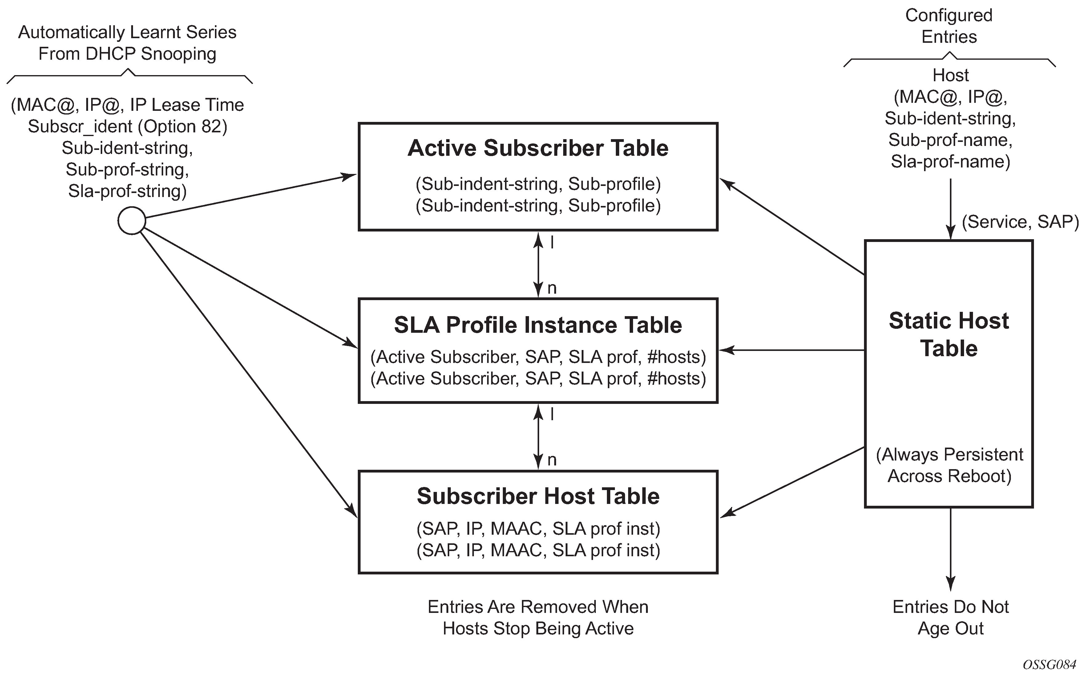
Active subscriber table
An entry is created in the active subscriber table when the first host (either dynamic or static) is created with a specific subscriber identification string. The entries are grouped by their subscriber identification string.
Fields for each entry in the active subscriber table include:
The subscriber identification string (see Subscriber identification string).
In use subscriber profiles (see Subscriber profile).
SLA profile instance table
An entry is created in the SLA profile instance table when the first subscriber host on a certain SAP is created that uses a specific SLA profile. All subsequent hosts of the same subscriber on the same SAP that use the same SLA profile are associated with this entry. When the last host on this SAP, using this SLA profile disappears, the SLA profile instance is deleted from the table and the associated queues are removed.
SLA profile instances cannot span multiple subscriber SAPs. If subscriber hosts from the same subscriber exist on multiple SAPs and are associated with the same SLA profile template, a separate SLA profile instance is created for each SAP.
Fields for each entry in the SLA profile instance table include:
Active subscriber
SAP
SLA profile
Number of active subscriber hosts that share this instance
Subscriber host table
An entry is created in the subscriber host table if anti-spoofing is enabled as well as:
The first host (dynamic or static) with a specific IP and MAC combination is created. If the anti-spoof is IP only, the MAC address is masked to all 0’s. If anti-spoof is MAC, only the IP address is 0.0.0.0. All dynamic hosts and static hosts with the same IP and MAC combination are associated with the same subscriber host entry. If the anti-spoof type includes IP (IP-only or IP/MAC), there can be at most two hosts associated with the entry: one dynamic and one static. If the anti-spoof type is MAC-only, there can be a combination of several dynamic and static hosts associated with the entry.
The non-prof-traffic is provisioned. Both IP and MAC address are all 0’s.
Fields for each entry in the subscriber host table include:
SAP
IP address
MAC address
SLA profile instance (enhanced mode only)
DHCP lease state table
An entry in the DHCP lease state table is created for each dynamic host. Fields for each entry in the lease state table include:
Assigned IP address
Assigned MAC address
Persistence key
ESM entities
Relationship between ESM entities illustrates the relationship between the main entities in Enhanced Subscriber Management:
A subscriber is associated with only one subscriber profile.
A subscriber can be associated with one or more SLA profile (a VPLS service with 2 different SAPs can have different SLA profiles for the same subscriber).
A maximum of one SLA profile instance is generated (including ingress and egress queues) per SAP per SLA profile.
One or more hosts can be assigned to each SLA profile instance (these share the same queues).
Figure 8. Relationship between ESM entities 
Instantiating a new host
When a DHCP ACK is received for a new subscriber host on a particular SAP:
The ACK message is parsed using the appropriate script.
An entry is generated in the subscriber host table with indexes:
The SAP on which the host resides
The assigned IP address
The assigned MAC address and as lookup parameters:
the subscriber profile
the SLA profile to be used (derived from using the script)
If this is the first host of a subscriber, an HQoS scheduler is instantiated using the ingress and egress scheduler policies referred to in the subscriber profile. Otherwise, if the subscriber profile of the new host equals the subscriber profile of the existing subscriber, the new host is linked to the existing scheduler. If the subscriber profile is different from the subscriber profile of the existing subscriber, a new scheduler is created and all the hosts belonging to that subscriber are linked to this new scheduler. The new subscriber profile does conflict with the subscriber profile provisioned for a static host or non-sub-traffic under the same SAP.
If this is the first host of a subscriber on a particular SAP using a particular SLA profile, an SLA profile instance is generated and added to the SLA profile instance table. This includes instantiating a number of queues, according to the ingress and egress QoS profiles referred to in SLA profile, optionally with some specific overrides defined in the SLA profile. Otherwise the host is linked to the existing SLA profile instance for this subscriber on this SAP.
Any QoS and IP filter policies defined on the SAP are still processed even if Enhanced Subscriber Management is enabled on the SAP. For IPv4 traffic that is dropped because of anti-spoofing, counters, logging, and mirroring can be used. All other Layer 2 traffic that is never blocked by anti-spoofing can be processed by applying a QoS policy on the SAP and can still be classified differently, by the dot1p value.
If insufficient hardware resources (queues) or software resources (profile instances) are available to support the new host, the DHCP ACK is dropped and an event is generated.
Packet processing for an existing host
Whenever an IP packet arrives on a subscriber-facing SAP on which Enhanced Subscriber Management (ESM) is enabled, a lookup is done in the subscriber host table using as the index the SAP, source IP address, and source MAC address.
If there is no entry, this means that the host is not using the assigned IP address, so the packet is dropped.
If there is an entry, this refers to the subscriber profile and SLA profile to be used.
ESM host lockout
This feature increasingly penalizes hosts that fail repeated login attempts within a configurable time interval. This is done by holding off on creation attempts for these hosts for a configured but adaptable time period. A transient failure, because of a misconfiguration, is quickly corrected and does not prevent the host from logging in within a reasonable amount of time. At the same time, a malicious client or a constantly misconfigured client is locked-out and does not take up resources impacting other clients.
A lockout time per host supports exponential back-off with each retry and failure cycle, starting with a configured minimum value and increasing up to a configured maximum. The lockout time can be reset to the configured minimum value if there is no failed retry within a configured time threshold. The configurable values include:
CLI syntax:
    lockout-reset-time seconds
    lockout-time [minseconds] [maxseconds]
    max-lockout-hosts hosts
If multiple retries/failure cycles occur within the lockout time, then lockout period is exponentially increased starting from configured minimum value up to the configured maximum value. The lockout is reset to the minimum value if there is no failed retry till this lockout time.
This mechanism is supported for both single and dual-stack PPPoE and IPoE (DHCP) hosts over 1:1 or N:1 static or managed SAPs. The hold-off timer maintenance is on a per host basis (as follows):
For 1:1 VLAN (PPPoE or IPoE hosts) per <VLAN, MAC address>
For N:1 VLAN (PPPoE or IPv4oE hosts) per <VLAN, agent-circuit-id, agent-remote-id, MAC@>
For 1:1 VLAN (IPv6oE hosts) per <VLAN, DUID>
A show lockout state for hosts is supported, for one or more of <SAP, MAC@, agent-circuit-id, agent-remote-id>.
A clear lockout state is supported for hosts for one or more of <SAP, MAC@, agent-circuit-id, agent-remote-id>.
Any changes in configured lockout values do not apply to hosts currently under lockout and only applies after these hosts are out of lockout.
Functionality
ESM lockout is supported for dual-stack PPPoE hosts, L2TP LAC hosts, dual-stack IPoE hosts, and ARP hosts. ESM Lockout tracks the following:
PPPoE PADI and PADR
DHCPv4 discover, DHCPv4 request, DHCPv6 solicit, DHCPv6 request
ARP Request
PPPoE session disconnect after successful session establishment
During lockout, authentication and ESM host creation is suppressed. A lockout context is created when a client first enters lockout. The context maintains state and timeout parameters for the lockout. If a lockout policy is configured for the underlying SAP for a host that has failed authentication or host creation, the host enters lockout for the configured minimum time (1 to 86400 seconds). When the lockout time expires, normal authentication and ESM host creation is resumed on relevant PPP or DHCP messages. In case of another failure, the host again enters the lockout state. The lockout time for the host on each failure is exponentially increased up to the configured maximum time (1 to 86400 seconds). The lockout time for a client is reset to the configured minimum value, and the corresponding lockout context is deleted, if there is no authentication (and host creation) failure within a configured amount of time that needs to elapse after the client initially enters lockout. This time is called the lockout-reset-time.
The host identification for lockout includes <SAP, MAC@, circuit ID, remote ID>.
ANCP and GSMP
Access Node Control Protocol management
Access Node Control Protocol Management (ANCP) can provide the following information to the router:
ANCP can communicate the current access line rate to the router. This allows the router to adjust the H-QoS subscriber scheduler with the correct rate or potentially change alarm when the rate goes below a set threshold. This allows a policy manager to change the entire policy when the rate drops below a minimal threshold value. The ANCP actual upstream synchronization rate is mapped to the ingress while ANCP actual downstream synchronization rate is mapped to the egress.
The router can send DSL line OAM commands to complete an OAM test from a centralized point or when operational boundaries prevent direct access to the DSLAM.
When ANCP is used with ESM, the ancp-string string can be returned from the Python script or from RADIUS. If not returned it defaults to the subscriber ID.
ANCP version 0x31 and 0x32 are both supported and are autodetected at the start of each ANCP session. Within version 0x32, partitioning is also supported.
Multiple partitions from the same access node are also supported. If partitions are used, they are automatically detected during the start of an ANCP session.
Static ANCP management
As depicted in Static ANCP management example, a DSLAM is connected to an aggregation network that is connecting the DSLAM to a BRAS. ANCP is used to provide SAP level rate management. The DSLAM in this application maintains multiple ANCP connections. The primary connection is to the BRAS, providing rate and OAM capabilities while the secondary is to the router to provide rate management.
7750 SR and 7450 ESS:
ESM dynamic ANCP
In this application ANCP is used between the DSLAM and the router to provide line control. There are multiple attributes defined as described below. ESM dynamic ANCP example depicts the connectivity model.
This application is used to communicate the following from the DSLAM to the router (the policy control point):
Subscriber rate
OAM
Figure 10. ESM dynamic ANCP example 
ANCP string
To support node communication with the access device the line rate, OAM commands, and so on. the node can use an ANCP string that serves as a key in the out-of-band channel with the access node. The string can be either provisioned in the static case, retrieved from RADIUS or from the Python script.
ANCP persistency support
Persistency is available for subscriber’s ANCP attributes and is stored on the on-board compact flash card. ANCP data stays persistence during an ISSU as well as nodal reboots. During recovery, ANCP attributes are first restored fully from the persistence file and incoming ANCP sessions are temporarily on hold. Afterwards new ANCP data can overwrite any existing values. This new data is then stored into the compact flash in preparation for the next event.
General Switch Management Protocol Version 3
General Switch Management Protocol version 3 (GSMPv3) is a generic protocol that allows a switch controller node to establish and maintain connections with one or more nodes to exchange operational information. Several extensions to GSMPv3 exist in the context of broadband aggregation. These extensions were proposed to allow GSMPv3 to be used in a broadband environment as more information is needed to synchronize the control plane between access nodes (such as DSLAMs) and broadband network gateways (such as BRAS).
In the TPSDA framework, nodes fulfill some BRAS functionality, where per subscriber QoS enforcement is one of the most important aspects. To provide accurate per-subscriber QoS enforcement, the network element not only knows about the subscriber profile and its service level agreement but it is aware of the dynamic characteristics of the subscriber access circuit.
The most important parameters in this context are the subscriber-line capacity (DSL sync-rate) and the subscriber's channel viewership status (the actual number of BTV channels received by the subscriber in any point in time). This information can be then used to adjust parameters of aggregate scheduling policy.
Besides, the above-mentioned information, GSMPv3 can convey OAM information between a switch controller and access switch. The node can operate in two roles:
as the intermediate controller
The router terminates a connection from the DSLAM.
as the terminating controller
The router fulfills full the roll of BRAS.
The DSL forum working documents recommends that a dedicated Layer 2 path (such as, a VLAN in an Ethernet aggregation network) is used for this communication to provide a specific level of security. The actual connection between DSLAM and BRAS is established at TCP level, and then individual messages are transported.
DHCP client mobility
Client mobility allows the node to use host monitoring (SHCV, ANCP, split DHCP) to remove network and server state when a host is removed locally. This allows for MAC addressed learned and pinned to move based on policy parameters.
Subscriber Host Connectivity Verification (SHCV) configuration is mandatory. This allows clients to move from one SAP to another SAP in the same service. This is only applicable in a VPLS service and group interfaces.
The first DHCP message on the new SAP with same MAC address (and IP address for group-interfaces) triggers SHCV and is always discarded.
SHCV checks that the host is no longer present on the SAP where the lease is currently populated to prevent spoofing. When SHCV detects that the host is not present on the original SAP, the lease-state is removed. The next DHCP message on the new SAP can initiate the host.
DHCP lease control
DHCP lease control allows the node to be configured to present a different lease to the client. This can be used to monitor the health of the client.
Using scripts for dynamic recognition of subscribers
Whenever a host belonging to a subscriber is activated (when a PC or set-top box (STB) is turned on), the host typically requests an IP address from the network using DHCP. See the DHCP Management section for an explanation of DHCP and DHCP snooping in the router.
The DHCP ACK response from the DHCP server can be parsed and the contents of the message can be used to identify the class to which this host belongs, and therefore, the QoS and security settings to apply.
The information necessary to select these settings can be codified in, the IP address by the DHCP server and the Option 82 string inserted by the DSLAM or other access node.
Python Language and Programmable Subscriber Configuration Policy
Python Language and Programmable Subscriber Configuration Policy (PSCP) is an identification mechanism using the Python scripting language. The PSCP references a Python script that can use regular expressions to derive the sub-ident-string, sub-profile-string and sla-profile-string from the DHCP response. A tutorial of regular expressions is beyond the scope of this guide, and can be found on the Internet (see https://docs.python.org/2/howto/regex.html).
A tutorial of Python is beyond the scope of this guide but can be found on the Internet (see http://www.python.org/).
Example scripts, using some regular expressions, can be found in Sample Python Scripts. See the Python Script Support for ESM section for more information about the service manager scripting language.
One or more scripts can be written by the operator and stored centrally on a server (in a location accessible by the router). They are loaded into each router at bootup.
Note that if a centrally stored script is changed, it is not automatically re-loaded onto the router. The reload must be forced by executing the shutdown and no shutdown commands on the affected URLs.
Determining the subscriber profile and SLA profile of a host
Data flow in determining subscriber profile and SLA profile describes the data flow while determining which subscriber profile and SLA profile to use for a specified subscriber host based on a snooped/relayed DHCP ACK for that subscriber host.
An incoming DHCP ACK (relayed or snooped) is processed by the script provisioned in the sub-ident-policy defined in the SAP on which the message arrived. This script outputs one or more of the following strings:
- sub-ident
- identifies the subscriber (always needed)
- sub-profile
- identifies the subscriber class (optional)
- sla-profile
- identifies the SLA Profile for this subscriber host (optional)
These strings are used for a lookup in one or more maps to find the names of the sub-profile and sla-profile to use. If none of the maps contained an entry for these strings, the names are determined based on a set of defaults.
Only when the names for both the sub-profile and sla-profile are known, the subscriber host can be instantiated. If even no default is found for either profile, the DHCP ACK is dropped and the host does not gain network access.
Determining the Subscriber Profile
All hosts (devices) belonging to the same subscriber are subject to the same HQoS processing. The HQoS processing is defined in the sub-profile. A sub-profile refers to an existing scheduler policy and offers the possibility to overrule the rate of individual schedulers within this policy.
Because all subscriber hosts of one subscriber use the same scheduler policy instance, they must all reside on the same I/O module.
Determining the subscriber profile shows how the sub-profile is derived, based on the sub-ident string, the sub-profile string and the provisioned data structures. The numbers associated with the arrows pointing toward the subscriber profiles indicate the precedence of the checks.
A lookup in the explicit-subscriber-map is done with the sub-ident string returned by the script. If a matching entry is found, the sub-profile-name (if defined) is taken. Otherwise:
If a sub-ident-policy is defined on the SAP, a lookup is done on its sub-profile-map with the sub-profile string from the script. The sub-profile-name is taken from the entry.
If no entry was found, then:
If provisioned, the sub-profile-name is taken from the def-sub-profile attribute on the SAP. If not provisioned, then:
The sub-profile with the name ‟default” is selected (if provisioned). If this is not provisioned, there are no other alternatives, the ACK is dropped, and the host does not gain access.
Determining the SLA profile
For each host that comes on-line, the router also needs to determine which SLA profile to use. The SLA profile determines for this host:
The QoS-policies to use:
classification
queues/policers
queue mapping
The egress scheduling policies use egress HQoS
The IP filter to use.
The SLA profile also has host-limits and session-limits attributes that limit the number of hosts or sessions per SLA profile instance.
The classification and the queue mapping are shared by all the hosts on the same forwarding complex that use the same QoS policy (by their SLA profile).
The queues and policers are shared by all the hosts (of the same subscriber) on the same SAP that are using the same SLA profile. In other words, queues and policers are instantiated when, on a specific SAP, a host of a subscriber is the first to use a specific SLA profile. This instantiation is referred to as an SLA profile instance. Ingress queues can be parented to a scheduler referenced in the ingress of a subscriber profile. Egress policers and queues can be parented to a scheduler referenced in the egress of a subscriber or SLA profile, or to a port scheduler.
A scheduler policy can be applied to the egress an SLA profile, allowing its schedulers to be the parent for its queues and for its tier 1 schedulers to be parented to a scheduler in a scheduler policy applied to the egress of a subscriber profile or a Vport, or to a port scheduler applied to a port or Vport. Configuring scheduler overrides is allowed for SLA profile egress schedulers. The configuration of a scheduler policy in the egress of an SLA profile is supported for all host types only on Ethernet interfaces. It is not supported for ESM over MPLS pseudowires, nor is HQoS adjustment and host tracking supported on its schedulers.
The following show, monitor and clear commands are available related to the SLA profile scheduler:
show qos scheduler-hierarchy subscriber sub-ident-string sla-profile sla-profile-
name
sap sap-id [scheduler scheduler-name] [detail]
The show qos scheduler-hierarchy subscriber command (shown above) displays the scheduler hierarchy with the SLA profile scheduler as the root. Note that if the SLA profile scheduler is orphaned (that is when the scheduler has a parent which does not exist) then the hierarchy is only shown when the show command includes the sla-profile and sap parameters.
If the SLA profile scheduler is orphaned (that is when the scheduler has a parent which does not exist) then the hierarchy is only shown when the show command includes the sla-profile and SAP parameters.
monitor qos scheduler-stats subscriber sub-ident-string [interval seconds] [repeat
repeat] [absolute|rate] sap sap-id sla-profile sla-profile-name

show qos scheduler-stats subscriber sub-ident-string sap sap-id sla-profile sla-
profile-name [scheduler scheduler-name]

clear qos scheduler-stats subscriber sub-ident-string sap sap-id sla-
profile sla-profile-name [scheduler scheduler-name]
Determining the SLA profile shows a graphical description of how the SLA profile is derived based on the subscriber identification string, the SLA profile string and the provisioned data structures. The numbers on the arrows toward the SLA profile indicate the priority of the provisioning (the lower number means the higher priority).
A lookup is done with the sub-ident string returned by the script in the explicit-subscriber-map. If a matching entry is found, the sla-profile-name is taken from it – if defined. Otherwise:
A lookup with the sla-profile string from the script is done in the sla-profile-map of the sub-profile found earlier. The sla-profile-name from the found entry is taken. If no entry was found, then:
A lookup is done with the sla-profile string in the sla-profile-map of the sub-ident-policy configured on the SAP. The sla-profile-name from the found entry is taken. If no sub-ident-policy was configured on the SAP or no entry was found, then:
If provisioned, the sla-profile-name is taken from the def-sla-profile attribute on the SAP. If not provisioned, there are no more alternatives, the ACK is dropped, and the host does not gain access.
SLA profile instance sharing
Each subscriber host or session has an SLA Profile Instance (SPI) associated with it. The SPI, is by default, determined by the subscriber ID, the SLA profile name, and the SAP where the subscriber host or session is active. See Relationship between ESM entities.
SPIs with the same SLA profile name, have the same configuration, however, the following functions are effective per SPI:
enforcing the different host limits
instantiation of queues and policers
accounting statistics
credit control functions
For a bridged Residential Gateway deployment, typically multiple IPoE or PPPoE sessions per subscriber are active on the BNG. The next sections describe the different SPI sharing mechanisms that apply for multiple subscriber sessions from the same subscriber, that are active on the same SAP with the same SLA profile name assigned.
SPI sharing per SAP
By default, all subscriber sessions or hosts from the same subscriber, active on the same SAP and with the same SLA profile assigned, share an SPI. The default SPI sharing is per SAP, as depicted in SLA profile instance per SAP.
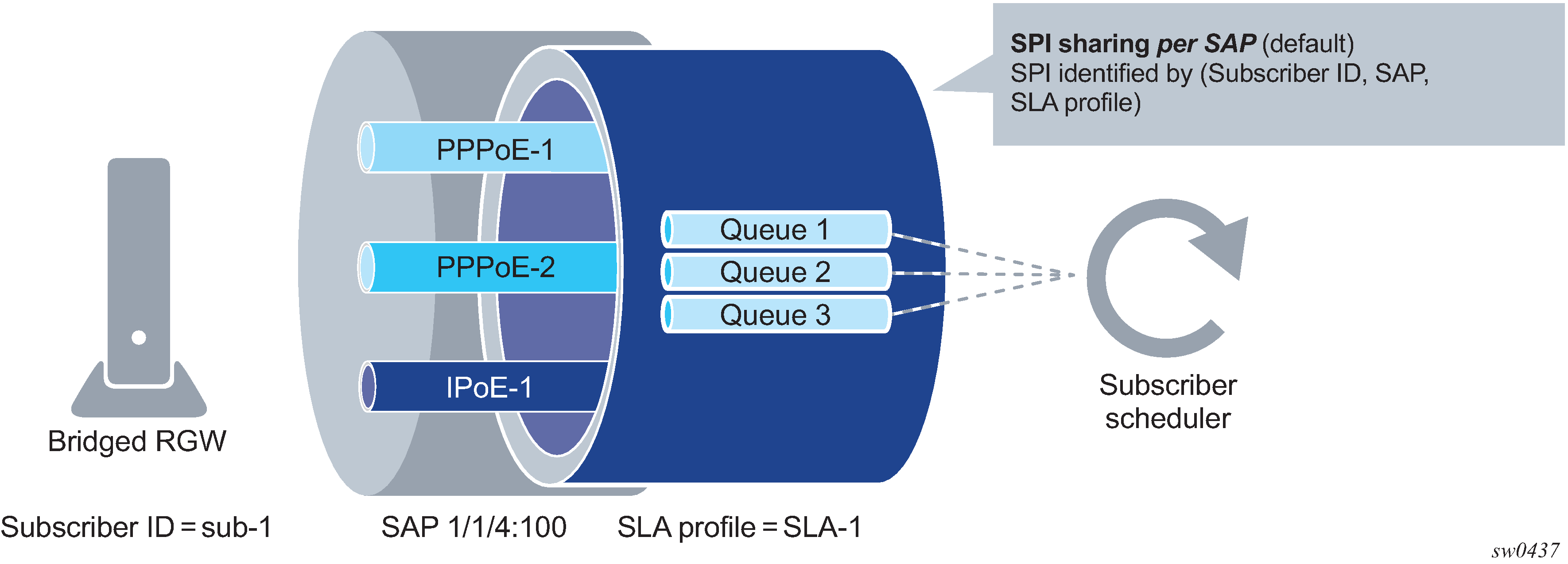
With SPI sharing per SAP, traffic from all subscriber sessions on a specific SAP and with the same SLA profile associated are mapped to the same set of queues and policers for QoS handling. Statistics from these queues and policers are also used in accounting. Per-host or per-session accounting modes cannot report counters for individual sessions unless their traffic is mapped in separate queues.
SPI sharing per SAP is the default configuration in an SLA profile and applies to PPPoE sessions, IPoE sessions (enabled on the group-interface) and IPoE hosts (IPoE sessions are disabled on the group-interface):
Example:
    configure
        subscriber-mgmt
            sla-profile "sla-profile-1"
                def-instance-sharing per-sap
SPI sharing per session
If QoS handling or accounting per-IPoE or per-PPPoE session is required, then the SPI sharing is configured to per-session sharing in the SLA profile:
Example:
    configure
        subscriber-mgmt
            sla-profile "sla-profile-1"
                def-instance-sharing per-session
Per-session sharing applies to PPPoE sessions and IPoE sessions (enabled on the group interface). An IPoE host setup fails when IPoE sessions are disabled on the group interface and per-session sharing is configured.
Each IPoE or PPPoE session from the same subscriber, active on the same SAP and having the same SLA profile assigned, has its own set of queues and policers. Per-session SPI sharing is depicted in SLA profile instance per session.

SPI per group
When even more granular control is needed over which sessions share an SPI, an SPI sharing group identifier can be specified during IPoE or PPPoE session authentication. This overrides the default SPI sharing method for that session as configured in the SLA profile.
Per-group SPI sharing is depicted in SLA profile instance per group. The same SPI is shared by all IPoE and PPPoE sessions from the same subscriber, active on the same SAP, having the same SLA Profile assigned and having the same SPI sharing group identifier.
SPI sharing per group is not supported on HSQ with hs-sla-mode single.

The SPI sharing group identifier is an integer value in the range 0 to 65535 and can be specified in authentication using:
A local user database lookup:
     configure
        subscriber-mgmt
           local-user-db local-user-db-name
              ipoe | ppp
                 host host-name
                    identification-strings
                       spi-sharing-group-id <group-id>
Configure no spi-sharing-group-id to apply the def-instance-sharing method as configured in the SLA profile.
RADIUS, by including the [241.26.6527.47] Alc-SPI-Sharing-Id VSA in an Access-Accept message:
Value "group:<group-id>" to enable SPI sharing per group identifier
Value "default" to apply the def-instance-sharing method as configured in the SLA profile
See the 7450 ESS, 7750 SR, and VSR RADIUS Attributes Reference Guide for a detailed description of the attribute.
Diameter NASREQ, by including the Vendor specific [NOKIA-1036] Alc-SPI-Sharing grouped AVP in an AA-Answer message:
        Alc-SPI-Sharing ::= < AVP Header: 1036 >
                                {Alc-SPI-Sharing-Type}
                                [Alc-SPI-Sharing-Id]
To enable SPI sharing per group identifier
[NOKIA-1037] Alc-SPI-Sharing-Type = 2
[NOKIA-1038] Alc-SPI-Sharing-Id = <group-id>
To apply the def-instance-sharing method as configured in the SLA profile use [NOKIA-1037] Alc-SPI-Sharing-Type = 0
See the Diameter and Diameter Applications, AA-Answer Message — Accepted Authorization AVPs section for a detailed description of the attribute.
Diameter Gx, by including the Vendor specific [NOKIA-1036] Alc-SPI-Sharing grouped AVP in a CCA message:
        Alc-SPI-Sharing ::= < AVP Header: 1036 >
                                {Alc-SPI-Sharing-Type}
                                [Alc-SPI-Sharing-Id]
To enable SPI sharing per group identifier
NOKIA-1037] Alc-SPI-Sharing-Type = 2
NOKIA-1038] Alc-SPI-Sharing-Id = <group-id>
To apply the def-instance-sharing method as configured in the SLA profile use [NOKIA-1037] Alc-SPI-Sharing-Type = 0
See 7750 SR and VSR Gx AVPs Reference Guide for a detailed description of the attribute.
Python:
alc.dts.setESM module: alc.dtc.SpiSharingGroupId = <group-id>
alc.esm.set module: alc.esm.SpiSharingGroupId = <group-id>
See the DHCP Management, ESM-Related Python Variables section for further details.
Per-group sharing applies to PPPoE sessions and IPoE sessions (enabled on the group interface). An IPoE host setup fails when IPoE sessions are disabled on the group interface and an SPI sharing group identifier is specified.
Dynamic changes of SLA profile and SPI sharing
During the lifetime of an IPoE or PPPoE session, the SLA profile and the SPI sharing can change. Such a dynamic change can be triggered by re-authentication, RADIUS CoA, or Diameter Gx RAR by specifying a new SLA profile and optionally, an SPI sharing group ID.
Dynamic changes of SPI Sharing describes the different transitions in SPI sharing because of re-authentication, RADIUS CoA, or Diameter Gx RAR.
| from - to |
SLA profile and SPI sharing info provided for dynamic change |
|---|---|
per sap - per sap |
SLA profile = <SLA profile name> SLA profile with "def-instance-sharing per-sap" [SPI sharing type = default]
|
per session - per session |
[SLA profile = <SLA profile name>] SLA profile with "def-instance-sharing per-session" [SPI sharing type = default]
|
per group - per group |
SLA profile = <SLA profile name> Optional. Current SLA profile name is used when not specified SPI sharing type = group SPI sharing ID = <group-id> Overrides the "def-instance-sharing" configured in the SLA profile |
per sap - per group |
SLA profile = <SLA profile name> Optional. Current SLA profile name is used when not specified SPI sharing type = group SPI sharing ID = <group-id> Overrides the "def-instance-sharing" configured in the SLA profile |
per session - per group |
SLA profile = <SLA profile name> Optional. Current SLA profile name is used when not specified SPI sharing type = group SPI sharing ID = <group-id> Overrides the "def-instance-sharing" configured in the SLA profile |
per group - per sap |
SLA profile = <SLA profile name> Optional. Current SLA profile name is used when not specified SPI sharing type = default SPI sharing ID must not be present ---------------------------------------------------------------- SLA profile = <SLA profile name> SLA profile with "def-instance-sharing per-sap" |
per group - per session |
[SLA profile = <SLA profile name>]
SPI sharing type = default SPI sharing ID must not be present --------------------------------------------- SLA profile = <SLA profile name> SLA profile with "def-instance-sharing per-session" |
per sap - per session |
SLA profile = <SLA profile name> SLA profile with "def-instance-sharing per-session" [SPI sharing type = default]
|
per session - per sap |
SLA profile = <SLA profile name> SLA profile with "def-instance-sharing per-sap" [SPI sharing type = default]
|
Identifying the SPI
An SPI is uniquely identified by the following characteristics:
the subscriber identifier
the SAP on which the subscriber session is active
the SLA profile name
An SPI sharing identifier that has two parts to support overlapping ids between groups and sessions:
SPI sharing type: per SAP, per IPoE session, per PPP session, per group
SPI sharing id:
an integer value determined by the system for SPI sharing per session
an integer value in the range 0 to 65535 specified by the user for SPI sharing per group
not required for SPI sharing per SAP
The following are examples for SPI representations in the system:
SPI sharing per SAP
A:PE-1# show service active-subscribers detail
===============================================================================
Active Subscribers
===============================================================================
-------------------------------------------------------------------------------
Subscriber sub-01 (sub-profile-12)
-------------------------------------------------------------------------------
--- snip---
-------------------------------------------------------------------------------
(1) SLA Profile Instance
- sap:[1/1/4:1201.41] (IES 1000 - group-int-1-1)
- sla:sla-profile-12
-------------------------------------------------------------------------------
--- snip---
A:PE-1# show service active-subscribers hierarchy
===============================================================================
Active Subscribers Hierarchy
===============================================================================
-- sub-01 (sub-profile-12)
   |
   +-- sap:[1/1/4:1201.41] - sla:sla-profile-12
       |
       |-- PPP-session - mac:00:51:00:00:01:41 - sid:1 - svc:1000
       |   |
       |   +-- 10.1.1.141 - IPCP
       |
       |-- PPP-session - mac:00:51:00:00:01:42 - sid:2 - svc:1000
       |   |
       |   +-- 10.1.1.142 - IPCP
       |
       +-- PPP-session - mac:00:51:00:00:01:43 - sid:3 - svc:1000
           |
           +-- 10.1.1.143 - IPCP
-------------------------------------------------------------------------------
Number of active subscribers : 1
Flags: (N) = the host or the managed route is in non-forwarding state
===============================================================================
*A:PE-1# show qos scheduler-hierarchy subscriber "sub-01" detail
===============================================================================
Scheduler Hierarchy - Subscriber sub-01
===============================================================================
--- snip ---
Root (Egr)
| slot(1)
|--(Q) : Sub=sub-01:sla-profile-12 1000->1/1/4:1201.41->6  (Port 1/1/4)
|   |    AdminPIR:1500       AdminCIR:1500
--- snip ---
SPI sharing per session
Note:Although they can have the same value as in the following output, an SPI sharing ID is not the same as the PPP session ID.
A:PE-1# show service active-subscribers detail
===============================================================================
Active Subscribers
===============================================================================
-------------------------------------------------------------------------------
Subscriber sub-01 (sub-profile-12)
-------------------------------------------------------------------------------
---snip---
-------------------------------------------------------------------------------
(1) SLA Profile Instance
- sap:[1/1/4:1201.41] (IES 1000 - group-int-1-1)
- sla:sla-profile-12 PPP session:10
-------------------------------------------------------------------------------
---snip---
A:PE-1# show service active-subscribers hierarchy
===============================================================================
Active Subscribers Hierarchy
===============================================================================
-- sub-01 (sub-profile-12)
   |
   |-- sap:[1/1/4:1201.41] - sla:sla-profile-12 PPP session:10
   |   |
   |   |-- PPP-session - mac:00:51:00:00:01:41 - sid:10 - svc:1000
   |   |   |
   |   |   +-- 10.1.1.141 - IPCP
   |
   |-- sap:[1/1/4:1201.41] - sla:sla-profile-12 PPP session:11
   |   |
   |   |-- PPP-session - mac:00:51:00:00:01:42 - sid:11 - svc:1000
   |   |   |
   |   |   +-- 10.1.1.142 - IPCP
   |
   +-- sap:[1/1/4:1201.41] - sla:sla-profile-12 PPP session:12
       |
       +-- PPP-session - mac:00:51:00:00:01:43 - sid:12 - svc:1000
           |
           +-- 10.1.1.143 - IPCP
-------------------------------------------------------------------------------
Number of active subscribers : 1
Flags: (N) = the host or the managed route is in non-forwarding state
===============================================================================
A:PE-1# show qos scheduler-hierarchy subscriber "sub-01" detail
===============================================================================
Scheduler Hierarchy - Subscriber sub-01
===============================================================================
--- snip ---
Root (Egr)
| slot(1)
|--(Q) : Sub=sub-01:sla-profile-12:PPP-10 1000->1/1/4:1201.41->6  (Port 1/1/4)
|   |    AdminPIR:1500       AdminCIR:1500
--- snip ---
SPI sharing per-group
A:PE-1# show service active-subscribers detail
===============================================================================
Active Subscribers
===============================================================================
-------------------------------------------------------------------------------
Subscriber sub-01 (sub-profile-12)
-------------------------------------------------------------------------------
---snip---
-------------------------------------------------------------------------------
(1) SLA Profile Instance
- sap:[1/1/4:1201.41] (IES 1000 - group-int-1-1)
- sla:sla-profile-12 group:100
-------------------------------------------------------------------------------
---snip---
A:PE-1# show service active-subscribers hierarchy
===============================================================================
Active Subscribers Hierarchy
===============================================================================
-- sub-01 (sub-profile-12)
   |
   |-- sap:[1/1/4:1201.41] - sla:sla-profile-12 group:100
   |   |
   |   |-- PPP-session - mac:00:51:00:00:01:41 - sid:15 - svc:1000
   |   |   |
   |   |   +-- 10.1.1.141 - IPCP
   |   |
   |   |-- PPP-session - mac:00:51:00:00:01:42 - sid:14 - svc:1000
   |   |   |
   |   |   +-- 10.1.1.142 - IPCP
   |
   +-- sap:[1/1/4:1201.41] - sla:sla-profile-12 group:200
       |
       +-- PPP-session - mac:00:51:00:00:01:43 - sid:13 - svc:1000
           |
           +-- 10.1.1.143 - IPCP
-------------------------------------------------------------------------------
Number of active subscribers : 1
Flags: (N) = the host or the managed route is in non-forwarding state
===============================================================================
A:PE-1#  show qos scheduler-hierarchy subscriber "sub-01" detail
===============================================================================
Scheduler Hierarchy - Subscriber sub-01
===============================================================================
---snip---
Root (Egr)
| slot(1)
|--(Q) : Sub=sub-01:sla-profile-12:Group-100 1000->1/1/4:1201.41->6  (Port 1/1/4)
|   |    AdminPIR:1500       AdminCIR:1500
---snip---
In RADIUS accounting messages, the SPI is uniquely defined by the following attributes:
Example:
    configure
        subscriber-mgmt
            radius-accounting-policy "acct-policy-1"
                include-radius-attribute
                    subscriber-id
                    nas-port-id
                    sla-profile
                    spi-sharing
Example:
 NAS PORT ID [87] 13 1/1/4:1201.41
    VSA [26] 40 Nokia(6527)
      SUBSC ID STR [11] 6 sub-01
      SLA PROF STR [13] 14 sla-profile-12

    # SPI sharing per SAP:
    VSA [241.26] 3 NOKIA(6527)
      SPI SHARING_ID [47] 3 SAP
    # SPI sharing per session:
    VSA [241.26] 14 NOKIA(6527)
      SPI SHARING_ID [47] 14 PPP session:12
    # SPI sharing per group:
    VSA [241.26] 14 NOKIA(6527)
      SPI SHARING_ID [47] 9 group:100
SLA-based egress QoS marking
The egress QoS marking for subscriber host traffic is derived from the SAP egress QoS policy associated with a corresponding SAP, instead of from the SLA profile associated with the corresponding subscriber host. Therefore, no egress QoS marking (Dot1p marking is set to 0, the dscp/prec field is kept unchanged) is performed for traffic transmitted on a managed SAP because by default, sap-egress policy 1 is attached to every managed SAP.
The default value of the ‟qos-marking-from-sap” flag is enabled. This means that the qos-marking defined in the SAP egress QoS policy associated with the SAP is used. The default setting of this flag in a combination with managed-SAP results in the same behavior as in the current system (dot1p=0, dscp/prec is unchanged).
If the no qos-marking-from-sap command is executed, then both the Dot1p marking and DSCP marking are derived from the sla-profile.
Changing the flag setting in the SLA profile being used by any subscriber-hosts (this includes subscriber-hosts on managed-SAPs as well) is allowed.
The following MC traffic characteristics apply:
On Layer 3 subscriber interfaces, MC is not supported so it is impossible to enable it at the SAP level or at the sla-instance level.
On Layer 2 SAPs, IGMP snooping is supported while it is not supported on the SLA instance level. Therefore, any MC traffic transmitted at egress belongs to a SAP (meaning it uses SAP queues), instead of to an SLA instance.
The special case are SAPs with a profiled-traffic-only flag enabled. Although it is possible to define an sla-profile applicable to a Layer 2 host, this is not taken as reference for marking mc-traffic, but rather SAP settings are used.
Sub-id and brg-id names with lengths between 32 and 64 characters
Beginning with Release 20.2.R1, the length of sub-id and brg-id names increased from 32 characters to 64 characters. These are referred to as long sub-id and long brg-id. The length of the corresponding RADIUS attributes, Alc-SubscID-Str and Alc-BRG-ID, that are mapped to the long sub-id and long brg-id are also increased to 64 characters.
As a result of this length increase, all MIB tables containing sub-id and brg-id names are affected. In a majority of those tables, the sub-id and brg-id name length is directly increased from 32 characters to 64 characters. However, tables where the MIB OID key contains a sub-id or brg-id as one of the fields do not increase the size of the sub-id and brg-id fields because the maximum key size of 128 characters could be exceeded when the sub-id and brg-id names are combined to form the key. Because the maximum size of the key in the MIB tables is limited to 128 characters, the sub-id and brg-id length in such tables remains limited to 32 characters. This ensures that the MIB key does not exceed the maximum size of 128 characters. This also means that an operator-defined sub-id and brg-id name that is greater than 32 characters must be internally translated (within the SR OS) into a 32-character identification. Instead of truncating sub-id and brg-id names that are greater than 32 characters to a 32 characters value (which could lead to duplicate sub-ids or brg-ids), an internal and unique 32-character length sub-id and brg-id is automatically generated by the system. These internally generated sub-id and brg-id names are used in the following tables where the long sub-id and brg-id (>32characters) could lead to violations of the maximum key size (128 characters). The affected tables are:
TIMETRA-SUBSCRIBER-MGMT-MIB:
tmnxSLAProfInstOverridesEntry
tmnxSubSpiOvrEntry
tmnxSLAProfInstSubHostV2Entry
tmnxSubSpiHostEntry
tmnxSPICatEntry
tmnxSubSpiCatEntry
tmnxSpiEgrQosSchedStatsEntry
tmnxSPIEgrQosSchedStatsEntry
TIMETRA-NAT-MIB:
tmnxNatL2AwHostPlcyEntry
tmnxNatFwlHostEntry
tmnxNatFwd2Entry
The operator-defined long sub-id and long brg-id names are listed in these tables and replaced with the internally-generated version with a 32-character length version.
Potential violation of the maximum key size shows examples of sub-id and brg-id names where a long sub-id and long brg-id may lead to a violation of the maximum key size. The internally-generated ID begins with the _tmnx_ prefix:
| tmnxSubInfoSubIdent | otherKey | Attributes |
|---|---|---|
ABCshort |
keyA1 |
existingInfoA1 |
ABCshort |
keyA2 |
existingInfoA2 |
_tmnx_sub_123 |
keyB1 |
existingInfoB1 |
_tmnx_brg_123 |
keyB2 |
existingInfoB2 |
_tmnx_sub_456 |
keyC |
existingInfoC |
ghiShort |
keyD |
existingInfoD |
The operator-defined sub-ids and brg-ids with lengths up to 32 characters are not affected by this change.
In most cases, operators are not concerned with the internal sub-id and brg-id which are only used by the system to access data in one of the 11 MIB tables where the long sub-id or long brg-id would otherwise violate the maximum length of the key. Therefore, the internal ID is not shown in the output of any show command.
An exception occurs when a SNMP table walk is performed in one of the 11 tables in which an entry of interest is found that contains an internal sub-id and brg-id, that needs to be connected with the real (long) subscriber identity.
This conversion can be performed and is aided by the MIB tables tmnxSubShortEntry (tmnxSubShortEntry ) and tmnxSubBrgShortEntry tables (tmnxSubBrgShortEntry ):
| tmnxSubShortId | tmnxSubLongId |
|---|---|
ABCshort |
ABCshort |
_tmnx_sub_123 |
defLongstring |
_tmnx_sub_456 |
JKLLongstring |
ghiShort |
ghiShort |
| tmnxSubBrgShortId | tmnxSubBrgLongId |
|---|---|
MNPshort |
ABCshort |
_tmnx_brg_333 |
xyzLongstring |
_tmnx_brg_222 |
OQRLongstring |
WVZShort |
WVZhort |
The mapping from long to an internal ID can be retrieved from the tmnxSubscriberInfoEntry (tmnxSubscriberInfoEntry ) and tmnxSubBrgEntry (tmnxSubBrgEntry ) tables:
| tmnxSubInfoSubIdent | attributes | tmnxSubInfoShortId |
|---|---|---|
ABCshort |
subscrInfoA |
ABCshort |
JKLlongstring |
subscrInfoC |
_tmnx_456 |
defLongstring |
subscrInfoB |
_tmnx_123 |
ghiShort |
subscrInfoD |
ghiShort |
| tmnxSubBrgId | attributes | tmnxSubBrgIdShort |
|---|---|---|
MNPshort |
subscrInfoM |
MNPshort |
OQRlongstring |
subscrInfoO |
_tmnx_222 |
xyzLongstring |
subscrInfoX |
_tmnx_333 |
WVZShort |
subscrInfoW |
WVZShort |
Online change of sub-id and brg-id
The sub-id and brg-id strings can be changed online with CLI and CoA/RAR (RADIUS and Diameter interfaces). Conversion between any combination of long and short sub-ids and short brg-ids is supported by moving each IPoE/PPPoE session or host under a new or renamed subscriber. This is performed by:
CoA
tools commands:
tools>perform>subscr-mgmt>edit-ipoe-session subscriber
tools>perform>subscr-mgmt>edit-lease-state subscriber
tools>perform>subscr-mgmt>edit-ppp-session subscriber
tools>perform>subscr-mgmt>edit-slaac-host subscriber
The above commands must be run separately for each host or session of the subscriber that is renamed.
Usage notes
This section describes the usage of sub-id and brg-id criteria.
Long sub-ids and long brg-ids are automatically enabled without having to explicitly enable them by provisioning additional CLI commands.
Although, the internal ANCP strings are 64 characters long, some of the external ANCP strings are limited to 63 characters. This is the limitation of the ANCP protocol and some of these strings are:
Access-Loop-Circuit-ID TLV
Access-Loop-Remote-ID TLV
Access-Aggregation-Circuit-ID-ASCII
Consequently, the maximum size of externally controlled ANCP parameters remains at 63 characters (such as the ANCP protocol, RADIUS, CLI). This means that when ANCP is used, the operators should restrict the sub-id string to a maximum of 63 characters, or always provide and explicit ANCP string that is a maximum of 63 characters in length.
Multicast host-tracking is not supported with long sub-ids. This means that the hosts with a sub-id longer than 32 characters are excluded from host tracking. The sub-id key length for host-tracking related MIB tables remain unchanged at 32 characters and only contains subs with short sub-ids.
The following MIBs are not supported for long sub-ids:
tmnxSubGrpTrkEntry
tmnxSubHostGrpTrkEntry
tmnxSubHostSapTrkEntry
tmnxSubHostTrkEntry
tmnxSubHostTrkStatsEntry
tmnxSubTrkPlcySubscriberEntry
tmnxSubTrkStatusEntry
Multicast host tracking only works with short sub-ids and is configured as follows:
configure
  subscriber-management
      host-tracking-policy <policy-name>
            egress-rate-modify [agg-rate-limit | scheduler <sch-name>]

configure
  subscriber-management
      sub-profile <subscriber-profile-name>
          host-tracking-policy <policy-name>  => mutually exclusive with igmp-policy
However, multicast HQoS adjustment is supported with long sub-ids, and should be deployed as a replacement for legacy multicast host tracking. Multicast HQoS adjustment is configured as follows:
configure subscriber-management igmp-policy <policy-name> egress-rate-modify [egress-aggregate-rate-limit | scheduler <name>] configure subscriber-management sub-profile <subscriber-profile-name> igmp-policy <policy-name>-
With the introduction of the long sub-id and long brg-id options, the show command output is rearranged by inserting additional line breaks and by wrapping the long sub-id and long brg-id at the end of the line. For example, the sub-id subidlong.123456789_123456789_123456789 123456789_123456789_3333 is wrapped as follows:
===============================================================================
Subscriber                             : subidlong.123456789_123456789_12345678
                                         9 123456789_123456789_3333
===============================================================================
In a multi-homing environment, the internal short sub-ids and short brg-ids are not synchronized. This means that they are independently derived on each node, meaning that if they are needed by the operator, they have to be retrieved by the management system after every switchover.
In most cases, the operator is not aware of the internal sub-id and brg-id. Their awareness is required only if an SNMP table walk is performed in one of the 11 MIB tables where the long sub-id and long brg-id causes the key to exceed the 128 character limit. If an entry with an internal sub-id or brg-id in one of the tables is found, then these internal values can be used to find the real (long) subscriber identity with a help of the conversion tables (tmnxSubShortEntry and tmnxSubBrgShortEntry).
Internally generated sub-ids and brg-ids are not saved in a persistency file. The sub-ids and brg-ids change after a reboot. Similar to multi-homing, if they are needed by the operator, they must be re-retrieved after a chassis reboot even when persistency is enabled.
Auto-sub ID
The subscriber ID name (sub-id) is a mandatory object that binds all hosts of a specific subscriber together. Briefly, the sub-id name represents a residential household. Many management/troubleshooting and even billing operations rely on the sub-id name entity. The sub-id name is required for the host creation process, and it can be supplied by any authentication source, such as RADIUS, Diameter, LUDB, or Python. It can be derived from the sap-id or can be statically provisioned in the form of a string.
In some ESM deployments, it is desirable that the sub-id is automatically generated within the router instead of burdening the OSS with this function. A typical application for auto sub-id is as follows:
RADIUS server provides the SLA profile string and the sub-profile string but not the sub-id string.
The sub-id name is automatically generated and formatted based on the configured options.
The following are the properties of auto sub-id generation:
The automatic generation of the subscriber ID name can be based on any combination of the following fields:
-
MAC address
-
sap-id
-
circuit-id
-
remote-id
-
session-id
There can be only a single set of subscriber identification fields defined per host type (IPoE or PPPoE) per chassis. If the combination of the fields must be modified, the existing subscribers with an automatically generated subscriber ID must be manually terminated. Considering that remote termination of the IPoE subscribers by a DHCP server is not supported by all DHCP client vendors through the FORCERENEW DHCP message (RFC 3203, DHCP reconfigure extension), changing the subscriber fields while subscribers with automatically generated subscriber ID are active should be avoided.
The subscriber ID name automatic generation takes place at the end of the host initiation process (after the authentication phase is completed) and only in case whereby the subscriber ID had not been already provided by any other more specific means (RADIUS, Diameter, LUDB, or Python).
The format of the sub-id name can be either a 10-character encoded string (characters A to Z and 0 to 9) or a user- friendly string based on the subscriber identification fields. The maximum length of the subscriber ID name is 64 characters.
The subscriber ID name is not passed in the Access-Request to the RADIUS server because it is generated after the authentication phase.
The subscriber ID name can be automatically generated regardless of how the SLA or subscriber profile strings are obtained (RADIUS, LUDB, Python, or static).
The subscriber identification fields used in automatic generation of the subscriber ID name are enabled at the system level.
CLI syntax:
    configure
    subscriber-mgmt
        auto-sub-id-key
            ppp-sub-id-key [mac] [sap-id] [circuit-id] [remote-id] [session-id]
            ipoe-sub-id-key [mac] [sap-id] [circuit-id] [remote-id] [dual-stack-remote-id]
If no sub-id-key per host type is configured, the defaults are:
PPPoE host type: |
mac, sap-id, session-id |
IPoE host type: |
<mac, sap-id>. |
The order in which the fields are configured is important because the subscriber ID name potentially becomes a concatenated string of the subscriber host identifiers in the order in which they are provisioned. The subscriber ID cannot be longer than 64 characters.
If the length of the concatenated fields for the subscriber ID name is longer than 64 characters, the host creation fails.
If the circuit ID or remote ID is in the key and they contain non-printable characters, their place in subscriber ID name are formatted in hex instead of ASCII. ASCII printable characters can contain the byte values 0x20 to 0x7E. All other values are ASCII non-printable and therefore, are formatted in hex characters.
The following would generate a subscriber ID name: xx:xx:xx:xx:xx:xx|1/1/3:23|44. The length of such subscriber ID name would be 29B.
mac: xx:xx:xx:xx:xx:xx
sap: 1/1/3:23
session-id: 44 (16bits length)
If the key contains the circuit ID as: 0x610163 (3 bytes), then the subscriber ID name is formatted as 610161, in hex, because 01 hex is non-printable in ASCII. Then the subscriber ID name’s length is 6B.
However, if the circuit ID is 0x616263 (3 bytes), then the string is formatted as ASCII string abc (three characters). The subscriber ID name’s length is 3B.
The assignment of the subscriber ID to dynamic hosts is performed in the following order:
From authentication sources: RADIUS, Diameter, LUDB, or Python.
A subscriber ID name obtained from authentication sources can conflict with the format of an implicit auto-generated subscriber ID name. When this happens, the subscriber host or session setup fails. Therefore, when implicit subscriber ID name generation is enabled (the default), a 10-character string containing the characters A to Z and 0 to 9 should not be returned from authentication sources. Information in Step 3 describes information to disable the implicit automatic generation of a subscriber ID name.
An explicit configured default is configured as def-sub-id:
At the SAP level for static SAPs:
configure
   service ies/vprn
      subscriber-interface <ip-int-name>
         group-interface <ip-int-name>
            sap <sap-id>
               sub-sla-mgmt
                  def-sub-id use-sap-id | use-auto-id | string <sub-id>
In the MSAP policy for managed SAPs:
configure
   subscriber-mgmt
      msap-policy <name>
         sub-sla-mgmt
            def-sub-id use-sap-id | use-auto-id | string <sub-id>
where:
use-sap-id: the sub-id name is the SAP identifier
use-auto-id: the sub-id name is a combination of the identifiers specified in auto-sub-id-key.
The sub-id name is in a readable format, that is, a concatenation of the fields in the pppoe-sub-id-key or ipoe-sub-id-key command separated by a ‟|” character.
string: the sub-id name is a user defined string
Implicitly generated default:
When no subscriber ID name is provided in authentication, and no explicit default is configured, then the system, by default, automatically generates a subscriber ID name, a 10-character string, using characters A to Z and 0 to 9, that is based on the fields defined in the:
ppp-sub-id-key command for PPP host types. If no such fields are explicitly defined, the default are assumed: mac, sap-id, session-id.
-
ipoe-sub-id-key command for IPoE host types. If no such fields are explicitly defined, the defaults are assumed: mac, sap-id.
The implicitly generated subscriber ID name is unique per chassis as well as in dual-homed environments.
The implicit automatic subscriber ID name generation can be disabled with the following command: configure subscr-mgmt auto-sub-id-key no implicit-generation.
The implicit auto-sub-id name generation cannot be disabled when there are active subscribers in the system with an implicit automatically generated subscriber ID name.
-
When disabled, the implicit auto-sub-id name generation cannot be enabled when there are active subscribers in the system.
With implicit subscriber ID generation disabled, the subscriber host or session setup fails when no subscriber ID name is provided in authentication, and no explicit default is configured. A 10-character subscriber ID name format, using the characters A to Z and 0 to 9, can be returned from authentication sources without risk of conflict.
Static subscribers are required to have the sub-id manually configured.
Sub-id identifiers
The sub-id can be based on any combination of the following identifiers:
The sap-id, in combination with any other allowable identifier, is used as the search key. This assumes a 1:1 (subscriber per SAP) deployment model.
The circuit-id, in combination with any other allowable identifier, is used to identify subscribers. This can be used in 1:1 deployment model, or in service per SAP deployment model. Circuit-id is applicable to IPoE v4 type hosts (option 82), to IPoE v6 type hosts (option 18 – interface-id) and PPPoE hosts (remote agent option signaled by PPPoE tags). The format of circuit-id is identical for IPv4 and IPv6 hosts.
The remote-id, in combination with any other allowable identifier, is used to identify subscribers. This can be used in 1:1 deployment model, or in service per SAP deployment model. The remote-id is applicable to IPoE v4 type hosts (option 82), to IPoE v6 type hosts (option 37) and PPPoE hosts (remote agent option signaled by PPPoE tags).
The mac address (in combination with any other allowable identifier is used to identify subscribers. This assumes a 1:1 deployment model.
The PPPoE session ID, in combination with any other allowable identifier, is applicable only to PPPoE hosts. The session ID used is the first host that is instantiated for the subscriber.
Dual-stack hosts
Auto-generation of sub-id names for subscribers with a single dual-stack hosts (IPoE and PPPoE) is enabled by default by not explicitly provisioning anything for the def-sub-id. The sub-id name would be semi-randomly generated based on the <mac, sap-id, session-id> for PPPoE hosts and the <mac, sap-id> combination for IPoE host.
Mixing hosts with auto-generated IDs and non-auto-generated IDs
Hosts with different sub-id names but identical auto-sub-id keys are not linked into the same subscriber. Such scenarios can arise with hosts with the same auto-sub-id keys but different methods for obtaining the sub-id name. For example, one host relying on auto-generated sub-id name while the other is using explicit configuration methods (sap-id, string, RADIUS or LUDB). If the auto-generated sub-id name and explicit sub-id name are the same, the host is tied into the same subscriber.
For example:
The default auto-sub-id for the following two hosts are <mac, sap-id>.
Host X on SAP 1/1/1:1 with MAC 00:00:00:00:00:01 obtains sub-id through RADIUS.
Host Y on SAP 1/1/1:1 with MAC 00:00:00:00:00:01 has sub-id auto-generated.
Regardless of which host comes up first, those two hosts at the end belong to different subscribers if their sub-ids are different.
Deployment considerations
The following is a deployment example scenario.
CLI syntax:
    config
     subscriber-mgmt
        auto-sub-id-key
            ppp-sub-id-key sap-id
            ipoe-sub-id-key mac circuit-id
CLI syntax:
    config
     service vprn 10
         subscriber-interface <ip-int-name>
         authentication-policy <auth-pol-name>
         group-interface <ip-int-name>
            sap 1
                sub-sla-mgmt
                    def-sub-id 	use-sap-id
                    sub-ident-policy <ident-pol-name>
            sap 2
                sub-sla-mgmt
                    def-sub-id auto-id
                    sub-ident-policy <ident-pol-name>
            sap 3
                sub-sla-mgmt
                    def-sub-id ‟sub3”
                    sub-ident-policy <ident-pol-name>
            sap 4
                sub-sla-mgmt
                        sub-ident-policy <ident-pol-name>
Assume the following cases:
RADIUS returns the sub-id on all four SAPs.
RADIUS does not return the sub-id string on any of the SAPs.
In the first case where RADIUS returns the sub-id string, on all four SAPs, the sub-id string is assigned by the RADIUS server. Defaults have no effect, and neither do identifiers specified under the auto-sub-id-key node.
In the second case, the effects are the following:
On SAP1 the sub-id name is the sap-id (1/1/1:3)
On SAP 2 the sub-id name is the sap-id for PPPoE hosts and <mac>-<circuit-id> concatenation for IPoE type hosts.
On SAP3 the sub-id name is the literal ‛sub3’ for PPPoE and IPoE hosts.
On SAP4 the sub-id name is a semi-random value based on the sap-id for PPPoE hosts and the <mac, circuit-id> combination for IPoE hosts.
Restrictions
Only a single combination of the subscriber fields used to auto generate sub-id is allowed per host type (IPoE or PPPoE) and per chassis. In case that the combination of the fields needs to be changed, the existing subscribers with an auto-generated sub-id must be manually terminated. Considering that remote termination of the IPoE subscribers by DHCP server is not supported by all DHCP client vendors through FORCERENEW DHCP message (RFC 3203), changing the subscriber fields while subscribers with auto generated sub-id are active should be avoided.
Limiting subscribers, hosts, and sessions
This section provides an overview of the different configuration options in SR OS to restrict the number of subscribers, subscriber hosts, and subscriber sessions.
multi-sub-sap
limits the number of subscribers (dynamic and static) on a SAP
lease-populate
limits the number of dynamic and static hosts on a SAP
host-limits
limits the number of dynamic and static hosts per type and address family; enforced per SLA profile instance or per subscriber
session-limits
limits the number of IPoE, PPPoE and L2TP sessions per SLA profile instance or per subscriber
The setup of a new subscriber host or session fails if any of these limits is reached.
Limiting the number of IPoE sessions
The number of IPoE sessions per SAP is limited with the sap-session-limit command configured in the group-interface ipoe-session context
The number of IPoE sessions per group interface or retail subscriber interface is limited with the session-limit command configured in the group-interface ipoe-session or retail subscriber-interface ipoe-session context.
IPoE sessions and subscriber hosts associated with IPoE sessions are subject to the per SLA profile instance host and session limits configured in the config>subscr-mgmt>sla-prof>host-limits context and to the per subscriber host and session limits configured in the config>subscr-mgmt>sub-prof context. See Limiting the number of hosts and sessions per SLA profile instance and per subscriber for a detailed description.
Limiting the number of PPPoE sessions
The number of PPPoE sessions per SAP is limited with the sap-session-limit command configured in the group-interface pppoe context.
To limit the number of PPPoE sessions per group interface or retail subscriber interface use the session-limit command configured in the group-interface pppoe or retail subscriber-interface pppoe context.
PPPoE sessions and subscriber hosts associated with PPPoE sessions are subject to the per SLA profile instance host and session limits configured in the config>subscr-mgmt>sla-prof>host-limits context and to the per subscriber host and session limits configured in the config>subscr-mgmt>sub-prof context. See Limiting the number of hosts and sessions per SLA profile instance and per subscriber for a detailed description.
Limiting the number of hosts and sessions per SLA profile instance and per subscriber
Host limits list the host limits and Session limits lists the session limits that can be configured in the following profiles:
sla-profile
The limits are enforced per SLA profile instance.
sub-profile
The limits are enforced per subscriber.
Example
For a bridged RGW, allow one dual stack IPoE session (IPv4 and IPv6 IA-PD) per SLA profile instance and up to two sessions per subscriber.
configure
    subscriber-mgmt
        sla-profile "sla-profile-1"
            description "host and sessions limits per SLA Profile Instance"
            host-limits
                ipv4-overall 1
                ipv4-arp 0
                ipv4-dhcp 1
                ipv6-pd-overall 1
                ipv6-wan-overall 0
            exit
            session-limits
                ipoe 1
                pppoe-overall 0
                l2tp-overall 0
            exit
        exit
        sub-profile "sub-profile-1"
            description "host and session limits per subscriber"
            session-limits
                overall 2
Host limit counters applicable per subscriber host type specifies the host-limits counters that are applicable for each of the different subscriber host types in SR OS. Session limit counters applicable per subscriber session type specifies the session-limits counters that are applicable for each of the different subscriber session types in SR OS.
Host and session limits are checked when the host or session is created in the system. When a limit is reached, the host or session setup fails, and an error event is logged. For example:
6338 2020/09/24 09:48:50.612 UTC WARNING: DHCP #2005 Base Lease State Population Error

"Lease state table population error on SAP 1/1/4:2111.1 in service 1000 - sub-profile 'sub-profile-1' : host-limit overall (1) exceeded for subscriber 'ipoe-001'"
When a host or session limit is reached for an ARP host, an IPoE host or an IPoE session, a host-limit-exceeded Subscriber Host Connectivity Verification (SHCV) can be triggered to clean up the state of disconnected devices.
| Command name | Description |
|---|---|
overall |
Limits the total number of subscriber hosts |
ipv4-overall |
Limits the total number of IPv4 hosts |
ipv4-arp |
Limits the number of IPv4 ARP hosts |
ipv4-dhcp |
Limits the number of IPv4 DHCP hosts |
ipv4-ppp |
Limits the number of IPv4 PPP hosts |
ipv6-overall |
Limits the total number of IPv6 hosts |
ipv6-pd-overall |
Limits the total number of IPv6 DHCP Prefix Delegation hosts (IA-PD) |
ipv6-pd-ipoe-dhcp |
Limits the number of IPv6 IPoE DHCP Prefix Delegation hosts (IA-PD) |
ipv6-pd-ppp-dhcp |
Limits the number of IPv6 PPPoE DHCP Prefix Delegation hosts (IA-PD) |
ipv6-wan-overall |
Limits the total number of IPv6 WAN hosts |
ipv6-wan-ipoe-dhcp |
Limits the number of IPv6 IPoE DHCP WAN hosts (IA-NA) |
ipv6-wan-ipoe-slaac |
Limits the number of IPv6 IPoE SLAAC WAN hosts |
ipv6-wan-ppp-dhcp |
Limits the number of IPv6 PPPoE DHCP WAN hosts (IA-NA). |
ipv6-wan-ppp-slaac |
Limits the number of IPv6 PPPoE SLAAC WAN hosts |
lac-overall |
Limits the total number of L2TP LAC hosts |
| Subscriber host type | Counts toward following host limits |
|---|---|
IPv4 - PPP Hosts - IPCP |
ipv4-ppp, ipv4-overall, overall |
IPv4 - PPP Hosts - PFCP |
— |
IPv4 - IPOE Hosts - DHCP |
ipv4-dhcp, ipv4-overall, overall |
IPv4 - IPOE Hosts - ARP |
ipv4-arp, ipv4-overall, overall |
IPv4 - IPOE Hosts - Static |
ipv4-overall, overall |
IPv4 - IPOE Hosts - PFCP |
— |
IPv4 - IPOE Mngd Hosts - Data-trig |
ipv4-overall, overall |
IPv4 - IPOE Mngd Hosts - AAA |
ipv4-overall, overall |
IPv4 - IPOE Mngd Hosts - GTP |
ipv4-overall, overall |
IPv4 - IPOE Mngd Hosts - Bonding |
ipv4-overall, overall |
IPv4 - IPOE Hosts BSM - DHCP |
— |
IPv4 - IPOE Hosts BSM - Static |
— |
IPv4 - IPOE BSM - DHCP |
— |
IPv4 - IPOE BSM - Static |
— |
IPv6 - PPP Hosts - SLAAC |
ipv6-wan-ppp-slaac, ipv6-wan-overall, ipv6-overall, overall |
IPv6 - IPOE Hosts - DHCP6 (NA) |
ipv6-wan-ppp-dhcp, ipv6-wan-overall, ipv6-overall, overall |
IPv6 - PPP Hosts - DHCP6 (PD) |
ipv6-pd-ppp-dhcp, ipv6-pd-overall, ipv6-overall, overall |
IPv6 - PPP Mngd Routes - DHCP6 (PD) |
— |
IPv6 - PPP Hosts - PFCP (SLAAC) |
— |
IPv6 - PPP Hosts - PFCP (NA) |
— |
IPv6 - PPP Hosts - PFCP (PD) |
— |
IPv6 - IPOE Hosts - SLAAC |
ipv6-wan-ipoe-slaac, ipv6-wan-overall, ipv6-overall, overall |
IPv6 - IPOE Hosts - DHCP6 (NA) |
ipv6-wan-ipoe-dhcp, ipv6-wan-overall, ipv6-overall, overall |
IPv6 - IPOE Hosts - DHCP6 (PD) |
ipv6-pd-ipoe-dhcp, ipv6-pd-overall, ipv6-overall, overall |
IPv6 - IPOE Mngd Routes - DHCP6 (PD) |
— |
IPv6 - IPOE Hosts - Static (WAN) |
ipv6-wan-overall, ipv6-overall, overall |
IPv6 - IPOE Hosts - Static (Pfx) |
ipv6-pd-overall, ipv6-overall, overall |
IPv6 - IPOE Hosts - PFCP (SLAAC) |
— |
IPv6 - IPOE Hosts - PFCP (NA) |
— |
IPv6 - IPOE Hosts - PFCP (PD) |
— |
IPv6 - IPOE Mngd Hosts - Data-trig (WAN) |
ipv6-wan-overall, ipv6-overall, overall |
IPv6 - IPOE Mngd Hosts - Data-trig (Pfx) |
ipv6-pd-overall, ipv6-overall, overall |
IPv6 - IPOE Mngd Routes - Data-trig (Pfx) |
— |
IPv6 - IPOE Mngd Hosts - AAA |
ipv6-wan-overall, ipv6-overall, overall |
IPv6 - IPOE Mngd Hosts - GTP (SLAAC) |
ipv6-pd-overall, ipv6-overall, overall |
IPv6 - IPOE Mngd Hosts - Bonding |
ipv6-pd-overall, ipv6-overall, overall |
IPv6 - IPOE BSM - DHCP6 (NA) |
— |
IPv6 - IPOE BSM - DHCP6 (PD) |
— |
L2TP LAC Hosts |
lac-overall, ipv4-overall, ipv6-overall, overall |
| Command name | Description |
|---|---|
overall |
Limits the total number of subscriber sessions |
ipoe |
Limits the number of IPoE sessions |
pppoe-overall |
Limits the total number of PPPoE sessions |
pppoe-local |
Limits the number of PPPoE local terminated sessions (PTA) |
pppoe-lac |
Limits the number of PPPoE L2TP LAC sessions |
l2tp-overall |
Limits the total number of L2TP sessions |
l2tp-lns |
Limits the number of L2TP LNS sessions |
l2tp-lts |
Limits the number of L2TP LTS sessions |
| Subscriber session type | Counts toward following session limits |
|---|---|
Local PPP Sessions - PPPoE |
pppoe-local, pppoe-overall, overall |
Local PPP Sessions - L2TP (LNS) |
l2tp-lns, l2tp-overall, overall |
LAC PPP Sessions - PPPoE |
pppoe-lac, pppoe-overall, overall |
LAC PPP Sessions - L2TP (LTS) |
l2tp-lts, l2tp-overall, overall |
IPOE Sessions |
ipoe, overall |
PFCP Sessions - PPP |
— |
PFCP Sessions - IPOE |
— |
PFCP Sessions - default tunnels |
— |
The host and session limits per SLA profile instance and per subscriber can be overridden at subscriber host or session creation by the following.
Include the 245.26.6527.5 Alc-Spi-Host-And-Session-Limits and 245.26.6527.6 Alc-Sub-Host-And-Session-Limits VSAs in the RADIUS Access-Accept message during authentication.
See the 7450 ESS, 7750 SR, and VSR RADIUS Attributes Reference Guide for a detailed description of the VSAs.
Include the NOKIA-1047 Alc-Spi-Host-And-Session-Limits and NOKIA-1048 Alc-Sub-Host-And-Session-Limits Vendor Specific Diameter AVPs in a CCA-I or CCA-U message during authentication.
See the 7750 SR and VSR Gx AVPs Reference Guide for a detailed description of the AVPs.
The combination of overrides and configured limits is only checked when the host or session is created.
Overrides are stored in the subscriber host and session ESM info and can be displayed using the following show commands:
show service id service-id dhcp lease-state detail
show service id service-id dhcp6 lease-state detail
show service id service-id slaac host detail
show service id service-id arp-host detail
show service id service-id ppp session detail
show service id service-id pppoe session detail
show service id service-id ipoe session detail
show service id service-id managed-hosts type {aaa | bonding | data-triggered | gtp | wpp}
For example:
# show service id 1000 ipoe session subscriber "ipoe-001" detail
===============================================================================
IPoE sessions for service 1000
===============================================================================
SAP                     : [1/1/4:2111.1]
Mac Address             : 0a:11:00:00:00:01
Circuit-Id              : pe1|1000|group-int-2-1|1/1/4:2111.1
Remote-Id               : 0a:11:00:00:00:01
Session Key             : sap-mac
--- snip ---
Subscriber Session Limit Overrides
 ipoe                   : 3
 pppoe-overall          : 0
 l2tp-overall           : 0
SLA Profile Instance Session Limit Overrides
 ipoe                   : 1
 pppoe-overall          : 0
 l2tp-overall           : 0
-------------------------------------------------------------------------------
Number of sessions : 1
===============================================================================
It is the operator's responsibility to keep consistency in the overrides that are stored per subscriber host and session by the following:
ensure that all hosts and sessions that belong to the same SLA profile instance receive the same dynamic SLA profile instance limit overrides
ensure that all hosts and sessions that belong to the same subscriber receive the same dynamic subscriber limit overrides
For existing hosts or sessions, this consistency can be achieved by a mid-session change, for example, by RADIUS CoA or Diameter Gx RAR or CCA-U.
Static subscriber hosts
While it is typically preferred to have all hosts provisioned dynamically through DHCP snooping, it may be needed to provide static access for specific hosts (those that do not support DHCP).
Because a subscriber identification policy is not applicable to static subscriber hosts, the subscriber identification string, subscriber profile and SLA profile must be explicitly defined with the host’s IP address and MAC address (if ESM is enabled).
If an SPI associated with the named SLA profile already exists on the SAP for the subscriber, the static subscriber host is placed into that SPI. If an SPI does not yet exist, one is created if possible. If the SLA profile cannot be created, or the host cannot be placed in the existing SPI (the host-limits was exceeded), the static host definition fails.
QoS for subscribers and hosts
QoS parameters in different profiles
QoS aspects for subscribers and hosts can be defined statically on a SAP or dynamically using.
ESM, for example, in a VLAN-per-service model, different services belonging to a single subscriber are split over different SAPs, and therefore the overall QoS (such as a scheduler policy) of this subscriber must be assigned using Enhanced Subscriber Management.
QoS parameters are shared among the subscriber profile and SLA profile as follows:
The subscriber profile refers to HQoS ingress and egress scheduler policies which define the overall treatment for hosts of this subscriber when queues are used, or policers managed by HQoS are used at egress. If the subscriber is using policers, the subscriber profile also refers to CFHP ingress and egress policer-control-policies which define the overall treatment for hosts of this subscriber.
The SLA profile refers to specific queue or policer settings for each host (BTV, VoIP, PC) using SAP ingress and SAP egress QoS policies. The SLA profile can also refer to an egress HQoS scheduler policy which defines the scheduling from the queues of the related host.
The primary use of the subscriber profile is to define the ingress and egress scheduler policies and policer control policies used to govern the aggregate SLA for all hosts associated with a subscriber. To be effective, the queues or policers defined in the SLA profile’s QoS policies references a scheduler or arbiter from the scheduler policy or policer-control-policy respectively as their parent.
QoS policy overrides
Generic QoS queue or policer parameters can be specified for the SAP in a QoS policy and overridden for some customers by queue and policer parameters defined in the SLA profile. This allows for a single SAP ingress and SAP egress QoS policy to be used for many subscribers, while providing individual subscriber parameters for queue or policer operation.
ESM subscriber hierarchical traffic control
ESM subscribers can make use of both queues and or policers for both the ingress and egress traffic. The queue and policers are configured within SAP ingress and egress policies applied to the SLA profile. The policers (at egress only) and queues can parent to different levels and cir-levels with different weights and cir weights of a virtual scheduler configured within a scheduler policy, and to an egress port scheduler configured in a port scheduler policy, to achieve hierarchical traffic control. The policers can parent to different levels with different weights of an arbiter configured within a policer control policies to achieve hierarchical traffic control.
Subscriber HQoS
Hierarchical QoS (HQoS) corresponds to scheduling bandwidth distribution to policers, queues and schedulers and is applied using scheduler policies at ingress and egress of the subscriber profile for a subscriber, and at egress in the SLA profile for a host, together with a port scheduler at both the port and Vport level.
Each scheduler policy can contain up to three tiers of schedulers with lower level schedulers being able to parent to higher level schedulers in the same scheduler policy.
Policers and queues can parent to any scheduler in their related scheduler policy hierarchy (except Vport at egress) and also at the egress to a port scheduler.
Schedulers can parent to any higher level scheduler in their related scheduler policy hierarchy and, at the egress to a port scheduler configured within the port or Vport. When an egress port scheduler is used, an aggregate rate limit can be applied at the subscriber profile and Vport levels instead of using a scheduler. To extend the hierarchy further at egress, a tier 1 scheduler within a scheduler policy can parent to any scheduler in a scheduler policy at a higher level.
The scheduling levels are composed of:
ingress and egress queues
egress policers
egress SLA-profile schedulers
ingress and egress subscriber profile schedulers
egress Vport schedulers
port schedulers
The ingress hierarchical parenting relationship options are shown in Ingress scheduling hierarchy options.

The egress hierarchical parenting relationship options are shown in Egress scheduling hierarchy options. Not all combinations can be configured concurrently, and some uses of port parent could be equally achieved using a scheduler parent and a child parent-location.
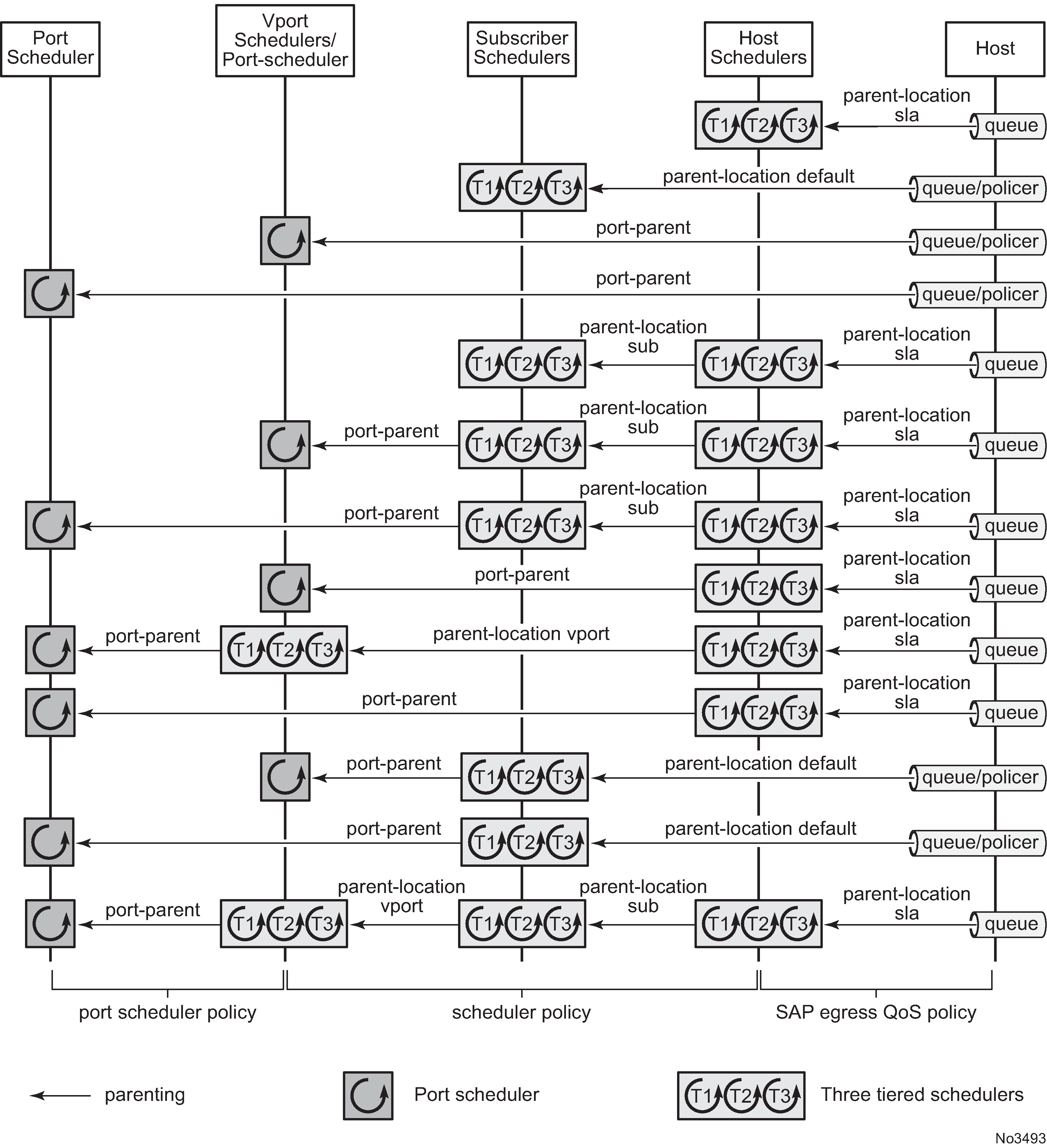
The parent command is used to specify the name of the parent scheduler when parenting a queue or scheduler, together with the level/cir-level and weight/cir-weight at which to connect.
config>qos>sap-ingress>queue# parent
  - parent scheduler-name [weight weight] [level level]
                            [cir-weight cir-weight] [cir-level cir-level]

config>qos>sap-egress>queue# parent
- parent scheduler-name [weight weight] [level level]
                            [cir-weight cir-weight] [cir-level cir-level]


config>qos>scheduler-policy>tier>scheduler# parent
- parent scheduler-name [weight weight] [level level]
                            [cir-weight cir-weight] [cir-level cir-level]
The location of the parent scheduler (in which applied scheduler policy it exists) for a policer or queue defaults to a scheduler in the subscriber ingress or egress scheduler policy. Parents of schedulers themselves must be explicitly configured and by default must be within the same scheduler policy.
At egress, the scheduler parenting relationship is determined using the parent-location command:
By default, egress queues parent to any scheduler in subscriber egress scheduler policy.
config>qos>sap-egress# parent-location default
Egress queues can parent to any scheduler within the scheduler policy applied to the egress of an SLA profile (this is not supported for policers managed by HQoS).
config>qos>sap-egress# parent-location sla
By default, a tier 1 scheduler in the scheduler policy is not allowed to be parented to another scheduler.
config>qos>scheduler-policy>tier# parent-location none
A tier 1 scheduler in the scheduler policy applied to the egress of an SLA profile can parent to a scheduler applied to the egress of a subscriber profile.
config>qos>scheduler-policy>tier# parent-location sub
A tier 1 scheduler in the scheduler policy applied to the egress of a subscriber profile can parent to a scheduler applied to the egress of a Vport.
config>qos>scheduler-policy>tier# parent-location vport
The configuration of a parent-location and frame-based accounting in a scheduler policy is mutually exclusive to ensure consistency between the different scheduling levels.
Note that the parent-location command is supported only on Ethernet interfaces. It is not supported for ESM over MPLS pseudowires.
Both egress queues and egress schedulers can port parent using directly to different levels/cir-levels, with different weights/cir weights, to a port egress port scheduler. Egress schedulers can also port parent directly to different levels/cir-levels, with different weights/cir weights, to a Vport egress port scheduler.
Subscriber CFHP
Class Fair Hierarchical Policing (CFHP) corresponds to the policing control of traffic by policers/arbiters. This uses policer control policies and can be applied for ingress and egress capacity control for the subscriber in the subscriber profile.
Each policer control policy can contain up to three tiers of arbiters with lower level arbiters being able to parent to higher level arbiters in the same scheduler policy.
Policers can parent to any arbiter in their related policer control policy hierarchy.
The policing levels are composed of:
Ingress and egress policers
Ingress and egress subscriber arbiters
- Ingress policed traffic uses the shared policer-output-queues to access the switch fabric. At egress, the policed traffic accesses the egress port through a queue group queue (by default the policer-output-queues queue group, though user configurable queue groups can also be used) or a locally configured subscriber queue.
- Egress policers can also be managed by HQoS.
The ingress hierarchical parenting relationship options are shown in Ingress policing hierarchy options.
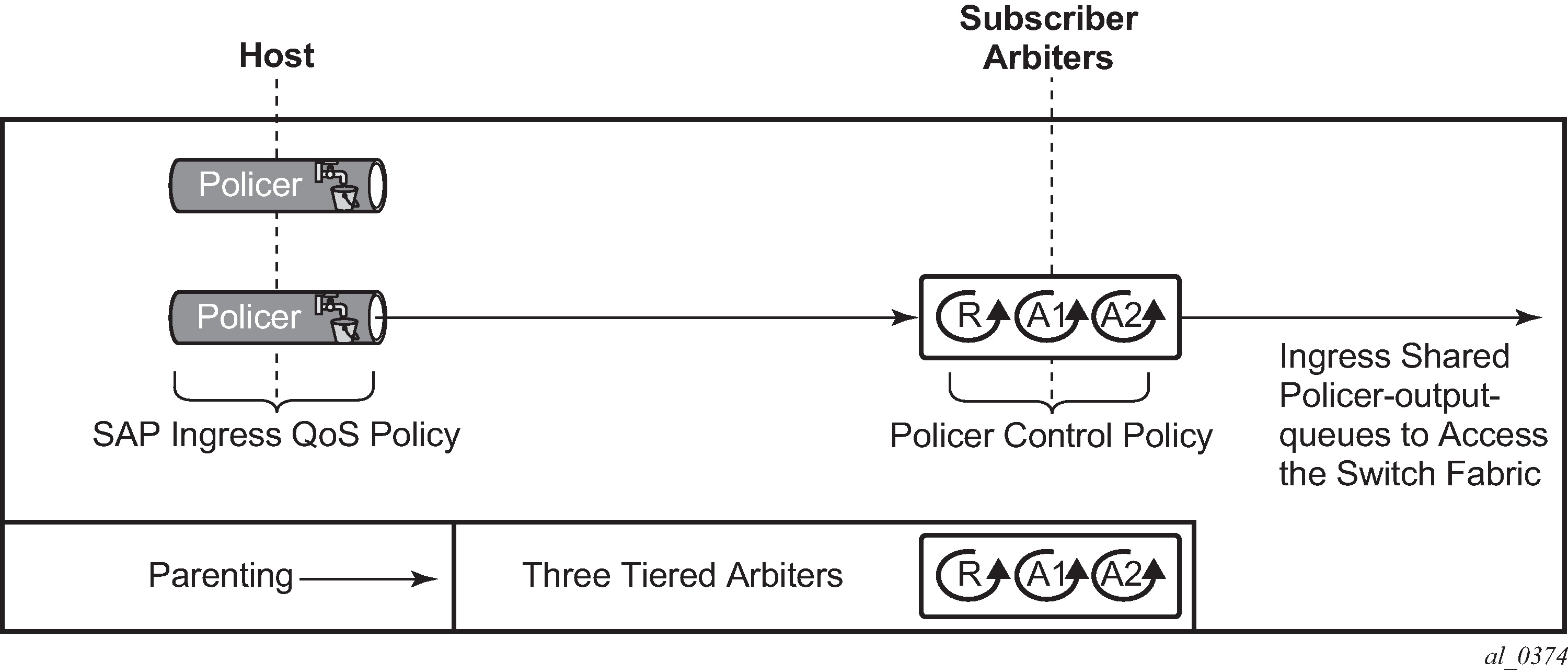
The egress hierarchical parenting relationship options are shown in Egress policing hierarchy options.
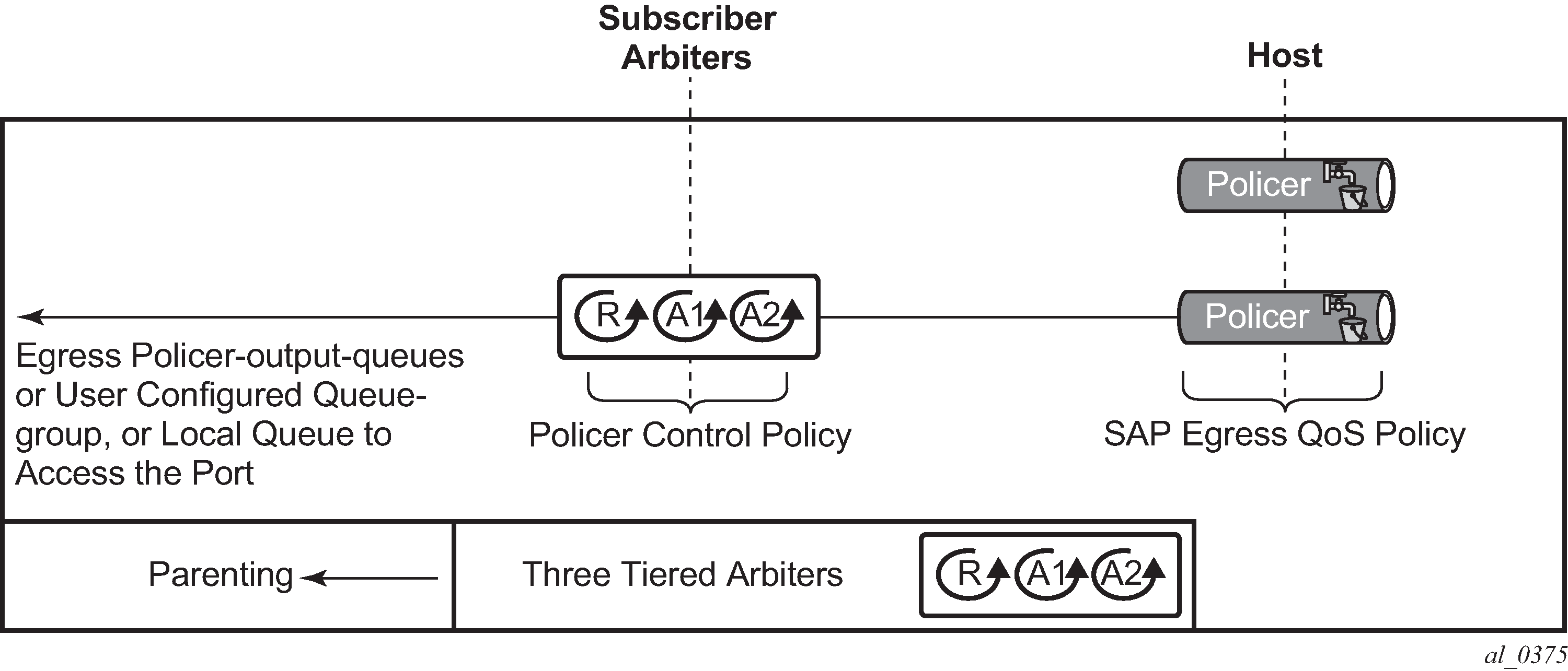
The parent command is used to specify the name of the parent arbiter when parenting a policer or arbiter, together with the level and weight at which to connect.
config>qos>sap-ingress>policer$ parent
  - parent arbiter-name [weight weight-level] [level level]

config>qos>sap-egress>policer$ parent
- parent arbiter-name [weight weight-level] [level level]

config>qos>plcr-ctrl-plcy>tier>arbiter# parent
- parent arbiter-name [weight weight-level] [level level]
ATM/Ethernet last-mile aware QoS for broadband network gateway
This feature allows the user to perform hierarchical scheduling of subscriber host packets in a way that the packet encapsulation overhead and ATM bandwidth expansion (when applicable) because of the last mile for each type of broadband session, that is, PPPoEoA LLC/SNAP and VC-Mux, IPoE, IPoEoA LLC/SNAP and VC-Mux, and so on, is accounted for by the 7450 ESS and 7750 SR acting as the Broadband Network Gateway (BNG).
The intent is that the BNG distributes bandwidth among the subscriber host sessions fairly by accounting for the encapsulation overhead and bandwidth expansion of the last mile so the packets are less likely to be dropped downstream in the DSLAM DSL port.
The last mile encapsulation type can be configured by the user or signaled using the Access-loop-encapsulation sub-TLV in the Vendor-Specific PPPoE Tags or DHCP Relay Options as per RFC 4679.
Furthermore, this feature allows the BNG to shape the aggregate rate of each subscriber and the aggregate rate of all subscribers destined for a specific DSLAM to prevent congestion of the DSLAM. The subscriber aggregate rate is adjusted for the last mile overhead. The shaping to the aggregate rate of all subscribers of a specific destination DSLAM is achieved by a new scheduling object, referred to as Virtual Port or Vport in CLI, which represents the DSLAM aggregation node in the BNG scheduling hierarchy
Broadband network gateway application
An application of this feature in a BNG is shown in BNG application.

Residential and business subscribers use PPPoEoA, PPoA, IPoA, or IPoEoA based session over ATM/DSL lines. Each subscriber host can use a different type of session. Although BNG application illustrates ATM/DSL as the subscriber last mile, this feature supports both ATM and Ethernet in the last mile.
A subscriber SAP is auto-configured through DHCP or the RADIUS authentication process, or is statically configured, and uses a Q-in-Q SAP with the inner C-VLAN identifying the subscriber while the outer S-VLAN identifies the Broadband Service Access Node (BSAN) which services the subscriber, such as, the DSLAM. The SAP configuration is triggered by the first successfully validated subscriber host requesting a session. Within each subscriber SAP, there can be one or more hosts using any of the above session types. The subscriber SAP terminates on an IES or VPRN service on the BNG. It can also terminate on a VPLS instance.
When the 7750 BNG forwards IP packets from the IP-MPLS core network downstream toward the Residential Gateway (RG) or the Enterprise Gateway (EG), it adds the required PPP and Ethernet headers, including the SAP encapsulation with C-VLAN/S-VLAN. When the BSAN node receives the packet, it strips the S-VLAN tag, strips or overwrites the C-VLAN tag, and adds padding to minimum Ethernet size if required. It also adds the LLC/SNAP or VC-mux headers plus the fixed AAL5 trailer and variable AAL5 padding (to next multiple of 48 bytes) and then segments the resulting PDU into ATM cells when the last mile is ATM/DSL. Thus the packet size undergoes a fixed offset because of the encapsulation change and a variable expansion because of the AAL5 padding when applicable. Each type of subscriber host session requires a different amount of fixed offset and may require a per-packet variable expansion depending on the encapsulation used by the session. The BNG node learns the encapsulation type of each subscriber host session by inspecting the Access-loop-encapsulation sub-TLV in the Vendor-Specific PPPoE Tags as specified in RFC 4679. The BNG node must account for this overhead when shaping packets destined for subscriber.
Queue determination and scheduling
BNG queuing and scheduling model illustrates the queuing and scheduling model for a BNG using the Ethernet or ATM last-mile aware QoS feature.
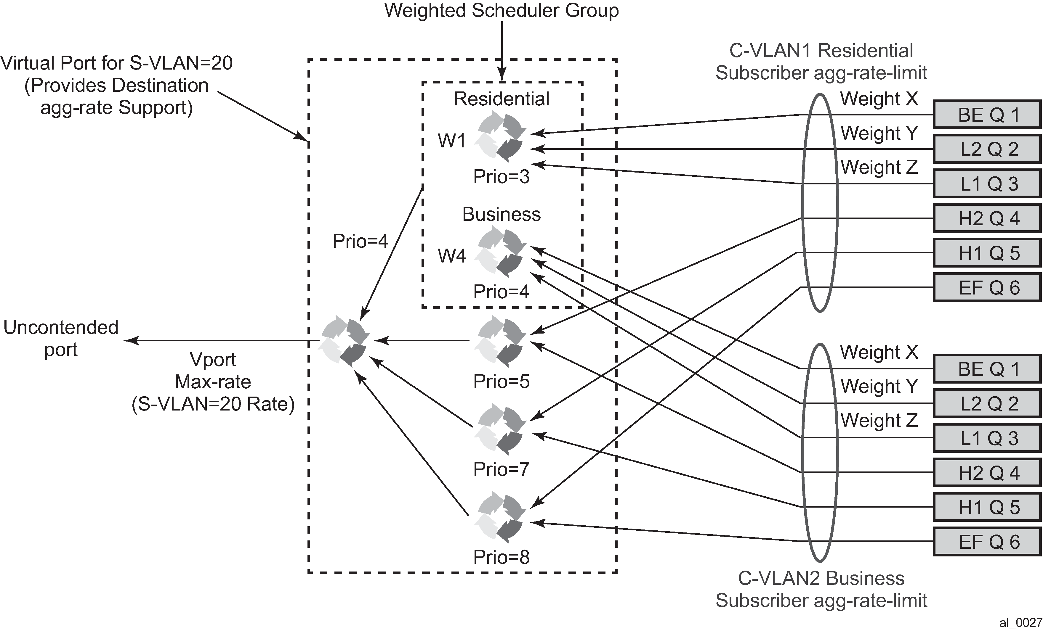
A set of per FC queues are applied to each subscriber host context to enforce the packet rate within each FC in the host session as specified in the subscriber’s host SLA profile. A packet is stored in the queue corresponding the packet’s FC as per the mapping of forwarding class to queue-id defined in the sap-egress QoS policy used by the host SLA profile. In the BNG application however, the host per FC queue packet rate is overridden by the rate provided in the RADIUS access-accept message. This rate represents the ATM rate that is seen on the last mile, that is, it includes the encapsulation offset and the per packet expansion because of ATM segmentation into cells at the BSAN.
To enforce the aggregate rate of each destination BSAN, a scheduling node, referred to as virtual port, and Vport is in the CLI. The Vport operates exactly like a port scheduler with the difference that multiple Vport objects can be configured on the egress context of an Ethernet port. The user adds a Vport to an Ethernet port using the following command:
CLI syntax:
config>port>ethernet>access>egress>vport vport-name create
The Vport is always configured at the port level even when a port is a member of a LAG. The vport-name is local to the port it is applied to but must be the same for all member ports of a LAG. It however does not need to be unique globally on a chassis.
CLI syntax:
config>port>ethernet>access>egress>vport vport-name create
The user applies a port scheduler policy to a Vport using the following command:
CLI syntax:
config>port>ethernet>access>egress>vport>port-scheduler-policy port-scheduler-policy-name
A Vport cannot be parented to the port scheduler when it is using a port scheduler policy itself. It is important the user ensures that the sum of the max-rate parameter value in the port scheduler policies of all Vport instances on a specific egress Ethernet port does not oversubscribe the port’s hardware rate. If it does, the scheduling behavior degenerates to that of the H/W scheduler on that port. A Vport which uses an agg-rate can be parented to a port scheduler. This is described in Applying aggregate rate limit to a Vport. Note that the application of the agg-rate, port-scheduler-policy and scheduler-policy commands under a Vport configuration are mutually exclusive.
Each subscriber host queue is port parented to the Vport which corresponds to the destination BSAN using the existing port-parent command:
CLI syntax:
config>qos>sap-egress>queue>port-parent [weight weight] [level level] [cir-weight cir-weight] [cir-level cir-level]
This command can parent the queue to either a port or to a Vport. These operations are mutually exclusive in CLI as described above. When parenting to a Vport, the parent Vport for a subscriber host queue is not explicitly indicated in the above command. It is determined indirectly. The determination of the parent Vport for a specified subscriber host queue is described in Vport determination and evaluation.
Furthermore, the weight (cir-weight) of a queue is normalized to the sum of the weights (cir-weights) of all active subscriber host queues port-parented at the same priority level of the Vport or the port scheduler policy. Because packets of ESM subscriber host queues are sprayed among the link of a LAG port based on the subscriber-id, it is required that all subscribers host queues mapping to the same Vport, such as having the same destination BSAN, be on the same LAG link so that the aggregate rate toward the BSAN is enforced. The only way of achieving this is to operate the LAG port in active/standby mode with a single active link and a single standby link.
The aggregate rate of each subscriber must also be enforced. The user achieves this by applying the existing agg-rate-limit command to the egress context of the subscriber profile:
CLI syntax:
config>subscr-mgmt>sub-profile>egress>agg-rate-limit agg-rate
In the BNG application however, this rate is overridden by the rate provided in the RADIUS access-accept message. This rate represents the ATM rate that is seen on the last mile, that is, it includes the encapsulation offset and the per packet expansion because of ATM segmentation into cells at the BSAN.
Weighted scheduler group
The existing port scheduler policy defines a set of eight priority levels with no ability of grouping levels within a single priority. To allow for the application of a scheduling weight to groups of subscriber host queues competing at the same priority level of the port scheduler policy applied to the Vport, or to the Ethernet port, a new group object is defined under the port scheduler policy:
CLI syntax:
config>qos>port-scheduler-policy>group group-name rate pir-rate [cir cir-rate]
Up to eight groups can be defined within each port scheduler policy. One or more levels can map to the same group. A group has a rate and optionally a cir-rate and inherits the highest scheduling priority of its member levels. For example, the scheduler group shown in the Vport consists of level priority 3 and level priority 4. It therefore inherits priority 4 when competing for bandwidth with the standalone priority levels 8, 7, and 5.
In essence, a group receives bandwidth from the port or from the Vport and distributes it within the member levels of the group according to the weight of each level within the group. Each priority level competes for bandwidth within the group based on its weight under congestion situation. If there is no congestion, a priority level can achieve up to its rate (cir-rate) worth of bandwidth.
The mapping of a level to a group is performed as follows:
CLI syntax:
config>qos>port-scheduler-policy>level priority-level rate pir-rate [cir cir-rate] group group-name [weight weight-in-group]
When a level is not explicitly mapped to any group, it maps directly to the root of the port scheduler at its own priority like in existing behavior.
Queue and subscriber aggregate rate configuration and adjustment
Software-Based Implementation
The subscriber aggregate rate is adjusted and based on an average frame size.
The user enables the use of this adjustment method by configuring the following option in the egress context of the subscriber profile:
CLI syntax:
config>subscr-mgmt>sub-profile>egress>encap-offset [type type]
This command allows the user to configure a default value to be used by all hosts of the subscriber in the absence of a valid signaled value. The following are configurable values:
pppoa-llc, pppoa-null, pppoeoa-llc, pppoeoa-llc-fcs, pppoeoa-llc-tagged, pppoeoa-llc-tagged-fcs, pppoeoa-null, pppoeoa-null-fcs, pppoeoa-null-tagged, pppoeoa-null-tagged-fcs, ipoa-llc, ipoa-null, ipoeoa-llc, ipoeoa-llc-fcs, ipoeoa-llc-tagged, ipoeoa-llc-tagged-fcs, ipoeoa-null, ipoeoa-null-fcs, ipoeoa-null-tagged, ipoeoa-null-tagged-fcs, pppoe, pppoe-tagged, ipoe, ipoe-tagged
Otherwise, the fixed packet offset is derived from the encapsulation type value signaled in the Access-loop-encapsulation sub-TLV in the Vendor-Specific PPPoE Tags as described in Section Signaling of Last Mile Encapsulation Type. Only signaling using PPPoE Tags is supported in the software based implementation. The last signaled valid value is then applied to all active hosts of this subscriber. If no value is signaled in the subscriber host session or the value in the fields of the Access-loop-encapsulation sub-TLV are invalid, then the offset applied to the aggregate rate of this subscriber uses the last valid value signaled by a host of this subscriber if it exists, or the user entered default type value if configured, or no offset is applied.
Configure the average frame size value to be used for this adjustment:
CLI syntax:
config>subscr-mgmt>sub-profile>egress>avg-frame-size bytes
The entered value must include the FCS but not the Inter-Frame Gap (IFG) or the preamble. If the user does not explicitly configure a value for the avg-frame-size parameter, then it is also assumed the offset is zero regardless of the signaled or user-configured value.
The computation of the subscriber aggregate rate consists of taking the average frame size, adding the encapsulation fixed offset including the AAL5 trailer, and then adding the variable offset consisting of the AAL5 padding to next multiple of 48 bytes. The AverageFrameExpansionRatio is then derived as follows:
AverageFrameExpansionRatio = (53/48 x (AverageFrameSize + FixedEncapOffset + AAL5Padding)) / (AverageFrameSize + IFG + Preamble).
When the last mile is Ethernet, the formula simplifies to:
AverageFrameExpansionRatio = (AverageFrameSize + FixedEncapOffset + IFG + Preamble) / (AverageFrameSize + IFG + Preamble).
The following are the frame size and rate applied to the subscriber queue and scheduler:
Subscriber Host Queue (no change):
Size = ImmediateEgressEncap + Data
Rate = ImmediateEgressEncap + Data
Subscriber Aggregate Rate Scheduler:
Size = ImmediateEgressEncap + Data
Rate = sub-agg-rate / AverageFrameExpansionRatio
Note that the CPM applies the AverageFrameExpansionRatio adjustment to the various components used in the determination of the net subscriber operational aggregate rate. It then pushes these adjusted components to IOM which then makes the calculation of the net subscriber operational aggregate rate.
The formula used by the IOM for this determination is:
sub-oper-agg-rate = min(sub-policy-agg-rate/AverageFrameExpansionRatio, ancp_rate/AverageFrameExpansionRatio) + (igmp_rate_delta/AverageFrameExpansionRatio),
where sub-policy-agg-rate is either the value configured in the agg-rate-limit parameter in the subscriber profile or the resulting RADIUS override value. In both cases, the CPM uses an internal override to download the adjusted value to IOM.
The value of sub-oper-agg-rate is stored in the IOM's subscriber table.
The following are the procedures for handling signaling changes or configuration changes affecting the subscriber profile:
If a new RADIUS update comes in for the aggregate subscriber rate, then a new subscriber aggregate ATM adjusted rate is computed by CPM using the last configured avg-frame-size and then programmed to IOM.
If the user changes the value of the avg-frame-size parameter, enables/disables the encap-offset option, or changes the parameter value of the encap-offset option, the CPM immediately triggers a re-evaluation of subscribers using the corresponding subscriber profile and an update the IOM with the new subscriber aggregate rate.
If the user changes the value of the agg-rate-limit parameter in a subscriber profile which has the avg-frame-size configured, this immediately triggers a re-evaluation of subscribers using the corresponding subscriber profile. An update to the subscriber aggregate rate is performed for those subscribers which rate has not been previously overridden by RADIUS.
If the user changes the type value of the encap-offset command, this immediately triggers a re-evaluation of subscribers using the corresponding subscriber profile. An update to the subscriber aggregate rate is performed for those subscribers which are currently using the default value.
If two hosts of the same subscriber signal two different encapsulation types, the last one signaled gets used at the next opportunity to re-evaluate the subscriber profile.
If a subscriber has a DHCP host, a static host or an ARP host, the subscriber aggregate rate continues to use the user-configured default encapsulation type value or the last valid encapsulation value signaled in the PPPoE tags by other hosts of the same subscriber. If none was signaled or configured, then no rate adjustment is applied.
Hardware-Based Implementation — The data path computes the adjusted frame size real-time for each serviced packet from a queue by adding the actual packet size to the fixed offset provided by CPM for this queue and variable AAL5 padding.
Like in the software based implementation, the user enables the use of the fixed offset and per packet variable expansion by configuring the following option in the egress context of the subscriber profile:
CLI syntax:
config>subscr-mgmt>sub-profile>egress>encap-offset [type type]
When this command is enabled, the fixed packet offset is derived from the encapsulation type value signaled in the Access-loop-encapsulation sub-TLV in the Vendor-Specific PPPoE Tags or DHCP Relay Options as described in Section Signaling of Last Mile Encapsulation Type.
If the user specifies an encapsulation type with the command, this value is used as the default value for all hosts of this subscriber until a host session signaled a valid value. The signaled value is applied to this host only and the remaining hosts of this subscriber continue to use the user entered default type value if configured, or no offset is applied. Hosts of the same subscriber using the same SLA profile and which are on the same SAP share the same instance of FC queues. In this case, the last valid encapsulation value signaled by a host of that same instance of the SAP egress QoS policy overrides any previous signaled or configured value.
The procedures for handling signaling changes or configuration changes affecting the subscriber profile are the same as in the software-based implementation with except for the following:
The avg-frame-size parameter in the subscriber profile is ignored.
If the user specifies an encapsulation type with the command, this value is used as the default value for all hosts of this subscriber until a host session signaled a valid value. The signaled value is applied to this host and other hosts of the same subscriber sharing the same SLA profile and which are on the same SAP. The remaining hosts of this subscriber continue to use the user entered default type value if configured, or no offset is applied.
If the user enables/disables the encap-offset option, or changes the parameter value of the encap-offset option, the CPM immediately triggers a re-evaluation of subscriber hosts using the corresponding subscriber profile and an update the IOM with the new fixed offset value.
If subscriber host session signals an encapsulation type at the session establishment time and subsequently sends a DHCP renewal message using a Layer 2 DHCP relay which does not insert option82 in a unicast message, the encapsulation type for this host does not change. TR-101 states that option82 is mandatory for DHCP broadcast messages).
If a subscriber has a static host or an ARP host, the subscriber host continues to use the user-configured default encapsulation type value or the last valid encapsulation value signaled in the PPPoE tags or DHCP relay options by other hosts of the same subscriber which use the same SLA profile instance. If none was signaled or configured, then no rate adjustment is applied.
The encapsulation type value signaled in DHCP relay options or PPPoE tags are not cross-checked against the host type. Thus, a host signaling PPPoA/LLC encapsulation type through DHCP relay options are not handled as if the packet included a PPPoE header when forwarded over the local Ethernet port. This results in applying an encap-offset in the data path which assumes the PPPoE header is added to forwarded packets over the local Ethernet port.
The encap-offset option forces all the rates to be either last-mile frame over the wire or local port frame over the wire, described as LM-FoW and FoW respectively. The system maintains a running average frame expansion ratio for each queue to convert queue rates between these two formats as described in Frame size, rates, and running average frame expansion ratio. The following are details of the queue and scheduler operation:
When the encap-offset option is configured in the subscriber profile, the subscriber host queue rates, that is, CLI and operational PIR and CIR as well as queue bucket updates, the queue statistics, that is, forwarded, dropped, and HQoS offered counters use the LM-FoW format. The scheduler policy CLI and operational rates also use LM-FoW format. The port scheduler max-rate and the priority level rates and weights, if a Weighted Scheduler Group is used, are always entered in CLI and interpreted as FoW rates. The same is true for an agg-rate-limit applied to a Vport. Finally the subscriber agg-rate-limit is entered in CLI as LM-FoW rate. When converting between LM-FoW and FoW rates, the queue running average frame expansion ratio value is used.
If the user enabled frame-based-accounting in a scheduler policy or queue-frame-based-accounting with subscriber agg-rate-limit and a port scheduler policy, the queue operational rate is capped to a user configured FoW rate. The scheduler policy operational rates are also in the FoW format. A user-configured queue avg-frame-overhead value is ignored because the running average frame expansion ratio is what is used when the encap-offset option is enabled.
If the user configured queue packet-byte-offset value, it is ignored and is not accounted for in the net packet offset calculation.
When no encap-offset is configured in the subscriber profile, that is, default and pre-R9.0 behavior, queue CLI and operational PIR and CIR rates, as well as queue bucket updates, the queue statistics, use data format. The scheduler policy CLI and operational rates also use data format. The port scheduler max-rate and the priority level rates and weights, if a Weighted Scheduler Group is used, and the subscriber agg-rate-limit are entered in CLI and interpreted as FoW rates. When converting between FoW and data rates, the queue avg-frame-overhead value is used and because this an Ethernet port, it is not user-configurable but constant and is equal to +20 bytes (IFG and preamble).
If the user enabled frame-based-accounting in a scheduler policy or queue-frame-based-accounting with subscriber agg-rate-limit and a port scheduler policy, the queue operational rate is capped to a user configured FoW rate in CLI which is then converted into a data rate using the queue avg-frame-overhead constant value of +20 bytes. The scheduler policy operational rates are in the FoW format.
If the user configured queue packet-byte-offset value, it adjusts the immediate packet size. This means that the queue rates, that is, operational PIR and CIR, and queue bucket updates use the adjusted packet size. In addition, the queue statistics are also reflected the adjusted packet size. Scheduler policy rates, which are data rates, use the adjusted packet size. The port scheduler max-rate and the priority level rates and weights, if a Weighted Scheduler Group is used, as well as the subscriber agg-rate-limit are always FoW rates and uses the actual frame size. Packet byte offset settings are not included in the applied rate when (queue) frame based accounting is configured, therefore, the offsets are applied to the statistics.
Frame size, rates, and running average frame expansion ratio
The following are the details of the rates and frame sizes applied to the subscriber host queues, the subscriber aggregate rate, and the Vport root scheduler for the scheduling model and when the encap-offset option is enabled in the subscriber profile.
Subscriber Host Queue:
Size = LastMileFrameOverWireEncap + Data
Rate = (48/53)* x (LastMileFrameOverWireEncap + Data)
*Applicable to ATM last-mile only.
Subscriber Aggregate Rate:
Size = LastMileFrameOverWireEncap + Data
Rate = (48/53)* x (LastMileFrameOverWireEncap + Data)
*Applicable to ATM last-mile only.
Vport/Port Scheduler and Weighted Scheduler Group
Size = FrameOverWireEncap + Data
Rate = FrameOverWireEncap + Data
When a frame arrives at the queue, the size is ImmediateEgressEncap+Data. This size is stored as the OfferedFrameSize so that the queue offered stats used in HQoS calculations are correct. See the HQoS-offered statistics as Offered.
This size is then adjusted by removing the ImmediateEgressEncap and adding the LastMileFrameOverWireEncap. This new adjusted frame size, referred as LastMileOfferedFrameSize, is then used for checking compliance of the frame against the queue PIR and CIR bucket sizes and for updating the queue forwarded and dropped stats.
The LastMileOfferedFrameSize value is computed dynamically for each packet serviced by the queue.
A new HQoS stat counter OfferedLastMileAdjusted is maintained for the purpose of calculating the running average frame expansion ratio, which is the ratio of the accumulated OfferedLastMileAdjusted and Offered of each queue:
RunningAverageFrameExpansionRatio = OfferedLastMileAdjusted / Offered
The vport/port port-scheduler hands out its FoW bandwidth in terms of Fair Information Rate (FIR) bandwidth to each subscriber queue. This queue FIR must be converted into LM-FoW format to cap it by the queue PIR (adminPIR) and to make sure the sum of FIRs of all queues of the same subscriber does not exceed the subscriber agg-rate-limit which is also expressed in LM-FoW format. The conversion between these two rates makes use of the cumulative RunningAverageFrameExpansionRatio value.
A queue LM-FoW AdminPIR value is always capped to the value of the local port FoW rate even if the conversion based on the current RunningAverageFrameExpansionRatio value indicates that a higher AdminPIR may be able to fill in the full line rate of the local port.
Vport determination and evaluation
In the BNG application, host queues of all subscribers destined for the same downstream BSAN, for example, all SAPs on the egress port matching the same S-VLAN tag value, are parented to the same Vport which matches the destination ID of the BSAN.
The BNG determines the parent Vport of a subscriber host queue, which has the port-parent option enabled, by matching the destination string associated with the subscriber with the string defined under a Vport on the port associated with the subscriber.
The user configures the dest string match under the egress Vport context of the Ethernet port associated with the subscriber:
CLI syntax:
config>port>ethernet>access>egress>vport>host-match dest string create
If a specific subscriber host queue does not have the port-parent option enabled, it is foster-parented to the Vport used by this subscriber and which is based on matching the dest string. If the subscriber could not be matched with a Vport on the egress port, the host queue is not bandwidth controlled and competes for bandwidth directly based on its own PIR and CIR parameters.
By default, a subscriber host queue with the port-parent option enabled is scheduled within the context of the port’s port scheduler policy. To indicate the option to schedule the queue in the context of a port scheduler policy associated with a Vport, the user enters the following command in SLA profile used by the subscriber host:
CLI syntax:
config>subscr-mgmt>sla-profile>egress>qos sap-egress-qos-policy-id vport-scheduler
This command is persistent meaning that the user can re-enter the qos node without specifying the vport-scheduler argument each time and the system remembers it. The user can revert to the default setting without deleting the association of the SLA profile with the SAP egress QoS policy by explicitly re-entering the command with the following new argument:
CLI syntax:
config>subscr-mgmt>sla-profile>egress>qos sap-egress-qos-policy-id port-scheduler
Applying aggregate rate limit to a Vport
The user can apply an aggregate rate limit to the Vport and apply a port scheduler policy to the port.
This model allows the user to oversubscribe the Ethernet port. The application of the agg-rate option is mutually exclusive to the application of a port scheduler policy, or a scheduler policy to a Vport.
When using this model, a subscriber host queue with the port-parent option enabled is scheduled within the context of the port’s port scheduler policy. However, the user must still indicate to the system that the queues are managed by the aggregate rate limit instance of a Vport by enabling the vport-scheduler option in the subscriber host SLA profile:
CLI syntax:
config>subscr-mgmt>sla-profile>egress>qos sap-egress-qos-policy-id vport-scheduler
A subscriber host-queue which is port-parented is parented to the port scheduler policy of the port used by the subscriber and aggregate rate limited within the instance of the Vport used by this subscriber and which is based on matching the dest string and org string.
If the specified subscriber host queue does not have the port-parent option enabled, it is foster-parented to the port used by this subscriber and aggregate rate limited within the instance of the Vport used by this subscriber. If the Vport exists but the port does not have a port scheduler policy applied, then the host queue is orphaned and no aggregate rate limit can be enforced.
Applying a scheduler policy to a Vport
The user can apply a scheduler policy to the Vport. This allows scheduling control of subscriber tier 1 schedulers in a scheduler policy applied to the egress of a subscriber or SLA profile, or to a PW SAP in an IES or VPRN service.
The advantage of using a scheduler policy under a Vport, compared to the use of a port scheduler (with or without an agg-rate), is that it allows a port parent to be configured at the Vport level.
Bandwidth distribution from an egress port scheduler to a Vport configured with a scheduler policy can be performed based on the level/cir-level and weight/cir-weight configured under the scheduler’s port parent. The result is in allowing multiple Vports, for example representing different DSLAMs, to share the port bandwidth capacity in a flexible way that is under the control of the user.
The configuration of a scheduler policy under a Vport is mutually exclusive to the configuration of a port scheduler policy or an aggregate rate limit.
A scheduler policy is configured under a Vport as follows:
CLI syntax:
config>port>ethernet>access>egress>vport# scheduler-policy scheduler-policy-name
When using this model, a tier 1 scheduler in a scheduling policy applied to a subscriber profile or SLA profiles must be configured as follows:
CLI syntax:
config>qos>scheduler-policy>tier# parent-location vport
If the Vport exists, but port does not have a scheduler policy applied, then its schedulers are orphaned and no port level QOS control can be enforced.
The following show/monitor/clear commands are available related to the Vport scheduler:
show qos scheduler-hierarchy port port-id vport name [scheduler scheduler-name]
[detail]

show qos scheduler-stats port port-id vport name [scheduler scheduler-name] [detail]

monitor qos scheduler-stats port port-id vport name [interval seconds ] [repeat
repeat] [absolute | rate]

clear qos scheduler-stats port port-id vport name [scheduler scheduler-name] [detail]
HQoS adjustment and host tracking are not supported on schedulers that are configured in a scheduler policy on a Vport, so the configuration of a scheduler policy under a Vport is mutually exclusive to the configuration of the egress-rate-modify parameter.
ESM over MPLS pseudowires are not supported when a scheduler policy is configured on a Vport.
Signaling of last mile encapsulation type
A subscriber host session can signal one of many encapsulation types each with a different fixed offset in the last mile. These encapsulation types are described in RFC 4679 and are illustrated in Subscriber host session encapsulation types and Access-loop-encapsulation sub-TLV. The BNG node learns the encapsulation type of each subscriber host session by inspecting the Access-loop-encapsulation sub-TLV in the Vendor-Specific PPPoE Tags as specified in RFC 4679.When Ethernet is the last mile, the encapsulation type results in a fixed offset for all packet sizes. When ATM/DSL is the last mile, there is an additional expansion because of AAL5 padding to next multiple of 48 bytes and which varies depending on the packet size.
The software and hardware based implementations support both ATM and Ethernet access using PPP encapsulation options. Thus, both provide support for the Access-loop-encapsulation sub-TLV in the Vendor-Specific PPPoEv4/PPPoEv6 Tags with the ATM encapsulation values and Ethernet encapsulation values. ATM and Ethernet access using IP encapsulation are only supported using default encapsulation offset configuration in the subscriber profile in the software based implementation. Support for signaling the Access-loop-encapsulation sub-TLV in the DHCPv4/DHCPv6 Relay Options is included in the hardware based implementation. There is no support for DHCPv6 relay options.

The operational last-mile values for hosts on the same SAP, having the same SLA profile are displayed in following the show command:
CLI syntax:
show>service active-subscribers>ale-adjust
The data-link can have values: atm, other and, unknown. If no offset is supplied it is set to unknown. other is used when the data-link is non-atm, otherwise it states atm.
Operational per-queue values can also be found in the show command:
CLI syntax:
show>qos>scheduler-hierarchy
The following is an example of displaying whether the queue is operating in last-mile mode.
Last mile ATM:
*A:Dut-C# /show service active-subscribers ale-adjust
===============================================================================
Active Subscriber Access Loop Encapsulation adjustment
===============================================================================
Subscriber
   SAP                                         SLA profile
   Data-link Offset(bytes)
-------------------------------------------------------------------------------
hpolSub81
   1/1/11:2000.1                               hpolSlaProf1
   atm       -10
-------------------------------------------------------------------------------
No. of Access Loop Encapsulation adjustments: 1
===============================================================================

*A:Dut-C# show qos scheduler-hierarchy subscriber "hpolSub81"
===============================================================================
Scheduler Hierarchy - Subscriber hpolSub81
===============================================================================
Ingress Scheduler Policy:
Egress Scheduler Policy :
-------------------------------------------------------------------------------
Root (Ing)
|
No Active Members Found on slot 1


Root (Egr)
| slot(1)
|--(Q) : Sub=hpolSub81:hpolSlaProf1 2000->1/1/11:2000.1->8->ATM  (Port 1/1/11)
|
|--(Q) : Sub=hpolSub81:hpolSlaProf1 2000->1/1/11:2000.1->7->ATM  (Port 1/1/11)
|
|--(Q) : Sub=hpolSub81:hpolSlaProf1 2000->1/1/11:2000.1->6->ATM  (Port 1/1/11)
|
|--(Q) : Sub=hpolSub81:hpolSlaProf1 2000->1/1/11:2000.1->5->ATM  (Port 1/1/11)
|
|--(Q) : Sub=hpolSub81:hpolSlaProf1 2000->1/1/11:2000.1->4->ATM  (Port 1/1/11)
|
|--(Q) : Sub=hpolSub81:hpolSlaProf1 2000->1/1/11:2000.1->3->ATM  (Port 1/1/11)
|
|--(Q) : Sub=hpolSub81:hpolSlaProf1 2000->1/1/11:2000.1->2->ATM  (Port 1/1/11)
|
|--(Q) : Sub=hpolSub81:hpolSlaProf1 2000->1/1/11:2000.1->1->ATM  (Port 1/1/11)
|
Last mile Ethernet:
*A:Dut-C# show service active-subscribers ale-adjust
===============================================================================
Active Subscriber Access Loop Encapsulation adjustment
===============================================================================
Subscriber
   SAP                                         SLA profile
   Data-link Offset(bytes)
-------------------------------------------------------------------------------
hpolSub81
   1/1/11:2000.1                               hpolSlaProf1
   other     +12
-------------------------------------------------------------------------------
No. of Access Loop Encapsulation adjustments: 1
===============================================================================

*A:Dut-C# show qos scheduler-hierarchy subscriber "hpolSub81"
===============================================================================
Scheduler Hierarchy - Subscriber hpolSub81
===============================================================================
Ingress Scheduler Policy:
Egress Scheduler Policy :
-------------------------------------------------------------------------------
Root (Ing)
|
No Active Members Found on slot 1


Root (Egr)
| slot(1)
|--(Q) : Sub=hpolSub81:hpolSlaProf1 2000->1/1/11:2000.1->8->Eth  (Port 1/1/11)
|
|--(Q) : Sub=hpolSub81:hpolSlaProf1 2000->1/1/11:2000.1->7->Eth  (Port 1/1/11)
|
|--(Q) : Sub=hpolSub81:hpolSlaProf1 2000->1/1/11:2000.1->6->Eth  (Port 1/1/11)
|
|--(Q) : Sub=hpolSub81:hpolSlaProf1 2000->1/1/11:2000.1->5->Eth  (Port 1/1/11)
|
|--(Q) : Sub=hpolSub81:hpolSlaProf1 2000->1/1/11:2000.1->4->Eth  (Port 1/1/11)
|
|--(Q) : Sub=hpolSub81:hpolSlaProf1 2000->1/1/11:2000.1->3->Eth  (Port 1/1/11)
|
|--(Q) : Sub=hpolSub81:hpolSlaProf1 2000->1/1/11:2000.1->2->Eth  (Port 1/1/11)
|
|--(Q) : Sub=hpolSub81:hpolSlaProf1 2000->1/1/11:2000.1->1->Eth  (Port 1/1/11)
|
Configuration example
The following CLI configuration achieves the specific use case shown in BNG queuing and scheduling model.
config
    qos
       port-scheduler-policy "dslam-vport-scheduler"
        group res-bus-be create
            rate 1000
        level 3 rate 1000 group res-bus-be weight w1
        level 4 rate 1000 group res-bus-be weight w4
        level 5 rate 1000 cir-rate 100
        level 7 rate 5000 cir-rate 5000
        level 8 rate 500 cir-rate 500
        max-rate 5000

       sap-egress 100                // residential policy
            queue 1                 // be-res
                port-parent weight x level 3
            queue 2                 // l2-res
                port-parent weight y level 3
            queue 3                 // l1-res
                port-parent weight z level 3
            queue 4                 // h2-res
                port-parent level 5
            queue 5                 // h1-res
                port-parent level 7
            queue 6                 // ef-res
                port-parent level 8
            fc be queue 1
            fc l2 queue 2
            fc l1 queue 3
            fc h2 queue 4
            fc h1 queue 5
            fc ef queue 6
        exit
        sap-egress 200                // business policy
            queue 1                 // be-bus
                     port-parent weight x level 4
            queue 2                 // l2-bus
                   port-parent weight y level 4
            queue 3                 // l1-bus
                      port-parent weight z level 4
            queue 4                 // h2-bus
                   port-parent level 5
            queue 5                 // h1-bus
                  port-parent level 7
            queue 6                 // ef-bus
                   port-parent level 8
            fc be queue 1
            fc l2 queue 2
            fc l1 queue 3
            fc h2 queue 4
            fc h1 queue 5
            fc ef queue 6
        exit
    exit

config
    sub-mgmt
        sla-profile "residential"
            egress
                qos 100 vport-scheduler
            exit
        exit
        sla-profile "business"
            egress
                qos 200 vport-scheduler
            exit
        exit
        sub-profile "residential"
            egress
               encap-offset
               avg-frame-size 1500
               agg-rate-limit 100
               exit
            exit
        exit
        sub-profile "business"
            egress
               encap-offset type pppoeoa-llc-tagged-fcs
               avg-frame-size 500
               agg-rate-limit 200
               exit
            exit
        exit
    exit

config
    port 1/1/1
        ethernet
            access
                egress
                    vport "dslam-1" create
                      port-scheduler-policy "dslam-vport-scheduler"
                        host-match dest ‟20” create
                        exit
                    exit
                exit
            exit
        exit
    exit
exit
Subscriber volume statistics
Subscriber volume statistics or octet and packet counters are available through the queues and policers that are instantiated for the subscriber. The queue and policer configuration is defined in the SLA profile using ingress and egress QoS policy associations with optional overrides. By default, subscriber hosts that belong to the same subscriber, that are active on the same SAP, and that have the same SLA profile share the set of queues and policers defined by that SPI. Alternatively, for bridged Residential Gateway scenarios, an SPI can be instantiated per subscriber session or per group identifier obtained during authentication. See SLA profile instance sharing for more details.
IP (Layer 3) volume accounting
Subscriber volume statistics by default count Layer 2 frame sizes optionally modified by configuration such as packet-byte-offset, last mile aware shaping, and so on.
To report subscriber volume statistics as Layer 3 (IP) packet sizes, the volume-stats-type can be configured to ip in the subscriber profile:
configure
    subscriber-mgmt
        sub-profile <subscriber-profile-name>
            volume-stats-type ip
volume-stats-type ip affects the subscriber statistics in SNMP, CLI, RADIUS accounting, XML accounting and Diameter Gx usage monitoring. Volume quota for RADIUS or Diameter Credit Control applications are interpreted as Layer 3 quota.
The following restrictions apply for volume-stats-type ip:
Layer 3/IP accounting is not supported in combination with MLPPP
Layer 3/IP accounting in combination with ESMoPW and last-mile-aware shaping may be inaccurate if the MPLS encapsulation overhead changes during the lifetime of a subscriber.
Layer 3/IP accounting is restricted to a single encap per sla-profile instance (queue instance). The first host associated with the sla-profile instance (queue instance) determines the allowed encapsulation. Conflicting encapsulations are:
PPPoE and IPoE on regular Ethernet SAPs
PPPoE and IPoE on PW SAPs
PPPoE keep alive packets do not contain IP payload and introduce an error in Layer 3/IP accounting when enabled in combination with L2TP-LAC. A workaround is to isolate the keep alives in a separate queue or policer.
Padding of frames smaller than the Ethernet minimum frame size (64B) may introduce an inaccuracy in Layer 3/IP accounting.
With ATM in the last mile, last-mile-aware shaping may introduce an inaccuracy in Layer 3/IP accounting.
Packet-Byte-Offset (PBO) changes during the lifetime of a subscriber introduces an inaccuracy in Layer 3/IP accounting.
Separate IPv4 and IPv6 counters
IPv4 and IPv6 forwarded and dropped subscriber traffic can be counted separately by a stat-mode v4-v6 command that is configured as a policer or queue qos override in the sla-profile. The stat-mode v4-v6 command is only applicable for Enhanced Subscriber Management (ESM).
configure subscriber-mgmt
        sla-profile "sla-profile-1" create
            ingress
                qos 10
                    queue 1
                        stat-mode v4-v6
                    exit
                    policer 1
                        stat-mode v4-v6
                    exit
                exit
            exit
            egress
                qos 10
                    queue 1
                        stat-mode v4-v6
                    exit
                    policer 1
                        stat-mode v4-v6
                    exit
                exit
            exit
        exit
For policers, the stat-mode command overrides the policer stat-mode configuration as defined in the sap-ingress or sap-egress qos policy. For information about sap-ingress and sap-egress policer stat-mode, see the 7450 ESS, 7750 SR, 7950 XRS, and VSR Quality of Service Guide. For a policer in stat-mode v4-v6, following counters are available:
Offered IPv4 octets and packets
Offered IPv6 octets and packets
Dropped IPv4 octets and packets
Dropped IPv6 octets and packets
Forwarded IPv4 octets and packets
Forwarded IPv6 octets and packets
When a policer’s stat-mode is changed while the SLA profile is in use, any previous counter values are lost and any new counters are set to zero.
For queues, a stat-mode is only available for use in Enhanced Subscriber Management (ESM) context to enable separate IPv4/IPv6 counters. For a queue in stat-mode v4-v6, following counters are available:
Offered High Priority, Low Priority, Uncolored, Managed octets and packets
Dropped IPv4 octets and packets
Dropped IPv6 octets and packets
Forwarded IPv4 octets and packets
Forwarded IPv6 octets and packets
A queue’s stat-mode cannot be changed while the SLA profile is in use.
There are no in-profile or out-of-profile forwarded and dropped counters for policers and queues in stat-mode v4-v6.
Non-IP traffic (for example PPPoE LCP frames) is counted against the IPv4 counters.
The separate IPv4 and IPv6 forwarded and dropped counters are reported in
SNMP
CLI
show service active-subscribers detail
- - - snip - - -
------------------------------------------------------------------------
SLA Profile Instance statistics
------------------------------------------------------------------------
                        Packets                 Octets

Off. HiPrio           : 0                       0
Off. LowPrio          : 1102685                 1102685000
Off. Uncolor          : 0                       0
Off. Managed          : 0                       0

Queueing Stats (Ingress QoS Policy 10)
Dro. HiPrio           : 0                       0
Dro. LowPrio          : 0                       0
For. InProf           : 0                       0
For. OutProf          : 0                       0
Dro. V4               : 0                       0
Dro. V6               : 0                       0
For. V4               : 367543                  367543000
For. V6               : 735142                  735142000

Queueing Stats (Egress QoS Policy 10)
Dro. InProf           : 0                       0
Dro. OutProf          : 0                       0
For. InProf           : 0                       0
For. OutProf          : 0                       0
Dro. V4               : 0                       0
Dro. V6               : 0                       0
For. V4               : 367543                  367543000
For. V6               : 735088                  735088000

------------------------------------------------------------------------
SLA Profile Instance per Queue statistics
------------------------------------------------------------------------
                        Packets                 Octets

Ingress Queue 1 (Unicast) (Priority) (Stats mode: v4-v6)
Off. HiPrio           : 0                       0
Off. LowPrio          : 1102685                 1102685000
Dro. V4               : 0                       0
Dro. V6               : 0                       0
For. V4               : 367545                  367545000
For. V6               : 735146                  735146000

Egress Queue 1 (Stats mode: v4-v6)
Dro. V4               : 0                       0
Dro. V6               : 0                       0
For. V4               : 367547                  367547000
For. V6               : 735096                  735096000

------------------------------------------------------------------------
SLA Profile Instance per Policer statistics
------------------------------------------------------------------------
                        Packets                 Octets

Ingress Policer 1 (Stats mode: v4-v6)
Off. V4               : 0                       0
Off. V6               : 0                       0
Dro. V4               : 0                       0
Dro. V6               : 0                       0
For. V4               : 0                       0
For. V6               : 0                       0

Egress Policer 1 (Stats mode: v4-v6)
Off. V4               : 0                       0
Off. V6               : 0                       0
Dro. V4               : 0                       0
Dro. V6               : 0                       0
For. V4               : 0                       0
For. V6               : 0                       0
RADIUS accounting
When a queue or policer is configured in stat-mode v4-v6, existing VSA’s are re-used in RADIUS detailed per queue or per policer accounting (configure subscriber-mgmt radius-accounting-policy name include-radius-attribute detailed-acct-attributes):
-
in-profile counter VSA’s map to IPv4 octets/packets
-
ingress queue high priority dropped counter VSA’s map to IPv4 octets/packets
-
out-of-profile counter VSA’s map to IPv6 octets/packets
-
ingress queue low priority dropped counter VSA’s map to IPv6 octets/packets
In addition the [26-6527-107] Alc-Acct-I-statmode / [26-6527-127] Alc-Acct-O-statmode is sent with value set to ‟v4-v6”.
Optionally a set of VSAs can be included in RADIUS accounting to report the aggregate IPv6 forwarded octets and packets of queues and policers with stat-mode v4-v6 enabled (configure subscriber-mgmt radius-accounting-policy name include-radius-attribute detailed-acct-attributes v6-aggregate-stats):
- [26-6527-194] Alc-IPv6-Acct-Input-Packets
- [26-6527-195] Alc-IPv6-Acct-Input-Octets
- [26-6527-196] Alc-IPv6-Acct-Input-GigaWords
- [26-6527-197] Alc-IPv6-Acct-Output-Packets
- [26-6527-198] Alc-IPv6-Acct-Output-Octets
- [26-6527-199] Alc-IPv6-Acct-Output-Gigawords
See the 7450 ESS, 7750 SR, and VSR RADIUS Attributes Reference Guide for a detailed description of all counter attributes.
-
-
XML accounting
The complete-subscriber-ingress-egress and custom-record-subscriber XML records use following fields to represent IPv4 and IPv6 forwarded/dropped octets and packets for queues or policers with stat-mode v4-v6 enabled:
- v4po - IPv4PktsOffered (policer only)
- v4oo - IPv4OctetsOffered (policer only)
- v6po - IPv6PktsOffered (policer only)
- v6oo - IPv6OctetsOffered (policer only)
- v4pf - IPv4PktsForwarded
- v6pf - IPv6PktsForwarded
- v4pd - IPv4PktsDropped
- v6pd - IPv4PktsDropped
- v4of - IPv4OctetsForwarded
- v6of - IPv6OctetsForwarded
- v4od - IPv4OctetsDropped
- v6od - IPv4OctetsDropped
For custom records, the following CLI is re-used to include v4/v6 counters if the queue is configured in stat-mode v4-v6:
i-counters
- all-packets-offered-count # n/a
- all-octets-offered-count # n/a
- high-packets-offered-count # n/a
- low-packets-offered-count # n/a
- uncoloured-packets-offered-count # n/a
- high-octets-offered-count # n/a
- low-octets-offered-count # n/a
- uncoloured-octets-offered-count # n/a
- all-packets-offered-count # n/a
- all-octets-offered-count # n/a
- high-packets-discarded-count # IPv4
- low-packets-discarded-count # IPv6
- high-octets-discarded-count # IPv4
- low-octets-discarded-count # IPv6
- in-profile-packets-forwarded-count # IPv4
- out-profile-packets-forwarded-count # IPv6
- in-profile-octets-forwarded-count # IPv4
- out-profile-octets-forwarded-count # IPv6
e-counters
- in-profile-packets-forwarded-count # IPv4
- in-profile-packets-discarded-count # IPv4
- out-profile-packets-forwarded-count # IPv6
- out-profile-packets-discarded-count # IPv6
- in-profile-octets-forwarded-count # IPv4
- in-profile-octets-discarded-count # IPv4
- out-profile-octets-forwarded-count # IPv6
- out-profile-octets-discarded-count # IPv6
Configuring IP and IPv6 filter policies for subscriber hosts
Access Control Lists (ACLs) for subscriber traffic are defined as IP and IPv6 filter policies and are configured in the SLA-profile associated with the subscriber. For information about IP and IPv6 filter policy configurations, see the 7450 ESS, 7750 SR, 7950 XRS, and VSR Router Configuration Guide.
config>subscr-mgmt>sla-prof
        sla-profile sla-profile-1 create
            ingress
                ip-filter 100
                ipv6-filter 300
            exit
            egress
                ip-filter 200
                ipv6-filter 400
            exit
       exit
Traffic from different subscriber hosts or sessions of a single subscriber and associated with the same sla-profile instance, is subject to the filter policies defined in the SLA profile.
Changing the IPv4 filter policy in an SLA profile in use by an active subscriber is allowed in the CLI, but not recommended. Changing the IPv6 filter policy in an SLA profile in use by an active subscriber is prevented in the CLI.
Dynamic updates of subscriber filter policies
The IP or IPv6 filter policy configuration of subscriber hosts can be dynamically updated using the mechanisms described in the next sections.
See the 7750 SR and VSR RADIUS Attributes Reference Guide for a detailed description of the RADIUS attributes format.
See the 7750 SR and VSR Gx AVPs Reference Guide for a detailed description of the Diameter AVP’s format.
SLA profile change
Changing the SLA profile of a subscriber host or session, implicitly changes its associated IP and IPv6 filter policies. An SLA profile change can be done by, for example, a RADIUS CoA or Diameter Gx RAR message. As the SLA profile also defines the QoS configuration for the subscriber hosts, this change may result in a discontinuity in accounting.
Override the IP and IPv6 filter policies
The ingress and egress IP and IPv6 filter policies can be overridden per subscriber host or session at creation time or mid-session:
-
from RADIUS by including the [26.6527.134] Alc-Subscriber-Filter attribute or the [245.26.6527.7.x] Alc-Subscriber-Filter-Name sub-attributes in an Access-Accept or CoA message
-
from Diameter Gx by including the Charging-Rule-Name AVP with the corresponding predefined name in a CCA or RAR message
-
Irrelevant fields (for example, IPv4 filters for an IPv6 host) are ignored.
-
If the ingress or egress field is missing in the VSA in a RADIUS CoA message, there is no change for that direction.
-
If the ingress or egress field is missing in the VSA in a RADIUS Access-Accept message, the IP filters as specified in the SLA profile are active for that direction.
-
An SLA profile IP filter override is applicable to all dynamic host types, including L2TP LNS but excluding L2TP LAC.
-
Filter name and filter ID overrides must not be mixed during the lifetime of a subscriber host or session. A filter override specified as a filter name and installed with the Alc-Subscriber-Filter-Name VSA in RADIUS takes precedence over a filter override specified as a filter ID using the Alc-Subscriber-Filter VSA in RADIUS or the Charging-Rule-Name AVP in Diameter Gx. For example, a CoA with Alc-Subscriber-Filter cannot override a filter that was previously installed as an override specified as a filter name with Alc-Subscriber-Filter-Name.
Insert subscriber host-specific filter entries
A subscriber host specific entry is a filter entry where the match criteria is automatically extended with the subscriber host IP or IPv6 address as source (ingress) or destination (egress) IP. They represent a per host customization of a generic filter policy: only traffic to or from the subscriber host that match against these entries.
A subscriber host specific entry is dynamically created from
a RADIUS Access-Accept or CoA message containing the [92] NAS-Filter-Rule or [26.6527.159] Alc-Ascend-Data-Filter-Host-Spec attribute
a Diameter CCA or RAR message containing the [92] NAS-Filter-Rule AVP embedded in the [3GPP-1005] Charging-Rule-Name AVP
The format used to specify host specific filter entries ([92] NAS-Filter-Rule format or [26.6527.159] Alc-Ascend-Data-Filter-Host-Spec format) cannot change during the lifetime of the subscriber host. A RADIUS message can only contain a single format for host specific filter entries. US message can only contain a single format for host specific filter entries.
Up to 10 host-specific filter rules can be specified in a single RADIUS or Diameter message. Each new RADIUS CoA or Diameter CCA/RAR message containing host specific filter attributes overwrites the previous subscriber host-specific filter entries for that host if there are enough free entries in the reserved range.
Subscriber host-specific filter entries can be removed with a [92] NAS-Filter-Rule attribute value equal to 0x00 or ‟ ‟(a space).
When the subscriber host session terminates or is disconnected, then the corresponding subscriber host-specific filter entries are also deleted.
Note that subscriber host-specific filter entries are moved if the subscriber host filter policy is changed (new SLA profile or IP filter policy override) and the new filter policy contains enough free reserved entries (sub-insert-radius).
A range of entries must be reserved for subscriber host specific entries in a filter policy:
config>filter
        ip-filter 100 create
            sub-insert-radius start-entry 1000 count 100
High and low watermarks can be configured to raise an event when the thresholds of free entries in the reserved range are reached:
 *A:cses-nokia>config>filter>ip-filter$ sub-insert-wmark ?
    - no sub-insert-wmark
    - sub-insert-wmark low <low-watermark> high <high-watermark>

   <low-watermark>      : [0..100]
   <high-watermark>     : [0..100]
Insert shared filter entries
The target application for shared filter entries is operators that have a predefined limited number of different filter lists that each are shared with multiple subscriber hosts or sessions and that are to be managed and activated from RADIUS or Diameter at authentication.
A local configured IP or IPv6 filter associated with a host or session (sla-profile or ip filter override) can be enhanced with dynamic filter entries that can be shared with multiple subscriber hosts or sessions. The shared dynamic filter entries are inserted with:
a set of RADIUS attributes ([26.529.242] Ascend-Data-Filter or [26.6527.158] Alc-Nas-Filter-Rule-Shared) received in a RADIUS Access-Accept or CoA message. A CoA message containing a set of one of those attributes overrides the previous set of shared filter entries active for that subscriber host or session.
a set of [6527-158] Alc-Nas-Filter-Rule-Shared AVP’s embedded in the [3GPP-1005] Charging-Rule-Name AVP received in a Diameter CCA or RAR message. The last received set of attributes overrides the previous set of shared filter entries for that subscriber host or session.
For each unique set of dynamic filter entries received per type (IPv4 or IPv6) and direction (ingress or egress), a copy is made of the local filter with the dynamic entries included at a preconfigured insert point. If the same set of dynamic filter entries is sent to subscriber hosts or sessions that have the same associated local filter, then they share the same filter copy. When there are no more subscriber hosts associated with a filter copy, then the filter copy is deleted. A filter copy is identified as local filter id:number. For example: show filter ip 10:2.
Shared filter entries are moved if the subscriber host filter policy is changed (new SLA profile or ip filter policy override) and if the new filter policy contains enough free reserved entries.

A range of entries must be reserved for shared entries in a filter policy:
config>filter>ip-filter
   sub-insert-shared-radius start-entry 100 count 10
High and low watermarks can be configured to raise an event when the thresholds of dynamic filter copies are reached:
*A:cses-V22>config>filter>ip-filter# shared-radius-filter-wmark ?
  - no shared-radius-filter-wmark
  - shared-radius-filter-wmark low <low-watermark> high <high-watermark>
 <low-watermark>      : [0..7999]
 <high-watermark>     : [1..8000]
The format used to specify shared filter entries ([26.6527.158] Alc-Nas-Filter-Rule-Shared format or [26.529.242] Ascend-Data-Filter format) cannot change during the lifetime of the subscriber host or session. A RADIUS message can only contain a single format for shared filter entries.
Shared filter entries can be removed with [26.6527.158] Alc-Nas-Filter-Rule-Shared attribute value equal to 0x00 or ‟ ‟ (a space).
Checking filter policy details
Use following show commands to check filter policy details and the filter configuration for a subscriber host:
CLI syntax:
    show filter ip ip-filter-id detail
    show filter ipv6 ip-filter-id detail
    show filter ip ip-filter-id type entry-type
    show filter ipv6 ipv6-filter-id type entry-type
 entry-type : fixed | radius-insert | credit-control-insert | radius-shared
    show service active-subscribers filter [subscriber sub-ident-string] [origin origin]
 sub-ident-string : [64 chars max]
 origin : radius | credit-control”
Multi-chassis synchronization
Dual-homing configuration shows the configuration under which synchronization of subscriber management information is performed. As depicted, a single access node aggregating several subscriber lines is dual- homed to redundant-pair of nodes.

Enabling subscriber management features (whether basic subscriber-management (BSM) or enhanced subscriber management (ESM)) causes the node to create and maintain state information related to a specific subscriber-host. This information is synchronized between redundant-pair nodes to secure non-stop service delivery in case of the switchover.
Overview
The synchronization process provides the means to manage distributed database (the Multi-Chassis Synchronization (MCS) database), which contains the dynamic state information created on any of the nodes by any application using its services. The individual entries in the MCS database are always paired by peering-relation, sync-tag and application-id. At any time the specified entry is related to the single redundant-pair objects (two SAPs on two different nodes) and therefore stored in a local MCS database of the respective nodes.
Internally, peering-relation and sync-tag are translated into a port and encapsulation value identifying the object (SAP) that the specified entry is associated with. The application-id then identifies the application which created the entry on one of the nodes. There are three basic operations that the application can perform on MCS database. The MCS database always synchronizes these operations with its respective peer for the specified entry.
The following principles apply:
add-operation
Any dynamic-state created in the application is pushed to the MCS database. MCS then creates and synchronizes with the corresponding peer provided (if configured). The application in the peer node is then notified as soon as the entry has been created. Similarly, the application in the local node (the node where the state has been created) is notified that entry has been synchronized (MCS is ‟in-sync” state). This operation is also used to modify existing MCS database entry.
local-delete
The MCS database entry is marked as no longer in use locally and this information is sent to the peer node. If the information is no longer used by applications on both nodes (the application in remote-node has already issued local-delete before), it is removed from database.
global-delete
The MCS database entry is removed from both nodes and from the application in the remote node.
The choice of the operation in corresponding situation is driven by the application. The following general guidelines are observed:
An event which leads to a dynamic-state deletion on a standby chassis is handled as ‟local-delete”.
An event which leads to a dynamic-state deletion on an active chassis is handled as ‟global-delete”.
An exception to above the rules is an explicit clear command which is handled as global-delete regardless of where the command was executed.
As previously stated, the MCS process automatically synchronizes any database operation with the corresponding peer. During this time, the MCS process maintains state per peer indicating to the applications (and network operator) the current status, such as in-sync, synchronizing or sync_down. These states are indicated by corresponding traps.
Loss of Synchronization and Reconciliation
Each time the connection between the redundant pair nodes is established or re-established, the MCS database is re-synchronized. There are several levels of connectivity loss that can have different effects on amount of data lost. To prevent massive retransmissions when the synchronization connection experiences loss or excessive delay, the MCS process implementation takes provisions to ensure following:
If a reboot of one or both nodes or establishing the peering for the first time, the full MCS database is reconciled.
If the MCS communication is lost and then re-established but neither node rebooted during the connection loss, only the information not synchronized during this time is reconciled (using sequence numbers helps identify information which was not synchronized).
If that MCS communication is lost because of excessive delay in ACK messages but no information has been effectively lost, the MCS process indicates a loss of synchronization but no reconciliation is performed.
DHCP lease state synchronization optimization
In a stateful BNG dual homing setup, Multi-Chassis Synchronization (MCS) is used to synchronize the subscriber state between the active and standby BNG, including the DHCP lease states, using configure redundancy multi-chassis options sub-mgmt configuration. For IPoE subscribers the synchronization includes DHCPv4 and DHCPv6 lease states and for PPPoE subscribers the synchronization includes DHCPv6 lease states.
The DHCP lease states are synchronized as follows:
when the lease is created in the system
at every DHCP renewal
when the lease is removed from the system
With short lease times in a scaled deployment, MCS synchronization creates additional load on the control plane. Short least times typically occur when the lease-split feature is enabled because a short lease time is used between the DHCP client and DHCP relay agent and a long lease time is used between the DHCP relay agent and DHCP server. With lease split enabled, the MCS application synchronizes the DHCP renewals following the short lease speed.
To reduce the control plane load in scaled multi-chassis redundant BNG deployments with short DHCP leases, a DHCP lease time threshold can be configured to control the eligibility of a DHCP lease for MCS synchronization at renewal:
# configure redundancy multi-chassis options sub-mgmt dhcp-leasetime-threshold
  - dhcp-leasetime-threshold [days <days>] [hrs <hours>] [min <minutes>] [sec <seconds>]
  - no dhcp-leasetime-threshold
 <days>               : [0..1]
 <hours>              : [0..23]
 <minutes>            : [0..59]
 <seconds>            : [0..59]
An active DHCP lease time threshold per multi-chassis peer is determined as the smallest value configured on either of the redundant BNGs:
# show redundancy multi-chassis sync peer 192.0.2.1
===============================================================================
Multi-chassis Peer Table
===============================================================================
Peer
-------------------------------------------------------------------------------
Peer IP Address         : 192.0.2.1
Peer Name               : mcs-pe2-pe1
Description             : (Not Specified)
Authentication          : Disabled
Source IP Address       : 192.0.2.2
Admin State             : Enabled
Sub-mgmt options        :
  DHCP lease threshold  : Active (10 minutes)
    Local / Remote      : 10 minutes / 15 minutes
The DHCP lease time threshold is inactive when unconfigured or unsupported on at least one end of the multi-chassis peer:
# show redundancy multi-chassis sync peer 192.0.2.1
===============================================================================
Multi-chassis Peer Table
===============================================================================
Peer
-------------------------------------------------------------------------------
Peer IP Address         : 192.0.2.1
Peer Name               : mcs-pe2-pe1
Description             : (Not Specified)
Authentication          : Disabled
Source IP Address       : 192.0.2.2
Admin State             : Enabled
Sub-mgmt options        :
  DHCP lease threshold  : Inactive
    Local / Remote      : 10 minutes / --
DHCP leases with lease time committed by the DHCP server less than or equal to the active DHCP lease time threshold are not synchronized at renewal, if only the remaining lease time is changed.
When lease split is active, the following rules apply if the short lease time is less than or equal to the active DHCP lease time threshold:
The DHCP lease is not synchronized when the DHCP client renewal or rebind is proxied, only the remaining short lease time is changed, and at least one DHCP server is reachable.
The DHCP lease is always synchronized when the DHCP client renewal or rebind is relayed to the DHCP server.
After an MCS redundancy switchover, DHCP leases that are flagged to skip MCS synchronization are granted the full lease time in the new active BNG. This could lead to a temporary address conflict when a client disconnects ungracefully immediately after such a switchover as illustrated in the following scenario:
A DHCP client lease with 15 minutes lease time is active on a redundant BNG pair with active DHCP lease time threshold equalling 20 minutes.
Five minutes after the last DHCP client renewal, an SRRP switchover occurs. At the new active BNG, the DHCP lease is eligible to be extended to the DHCP server committed lease time of 15 minutes while the client and server have a remaining lease time of 10 minutes.
If the client disconnects ungracefully before the next renewal (for example, by not sending a DHCP release), the state in the BNG is not cleared and the session lives longer than expected.
The lease in the DHCP server expires 10 minutes after the switchover, while the lease in the BNG is still active. The DHCP server can allocate the same address or prefix to another user, which could create a temporary address conflict in the BNG.
The MCS DHCP lease time threshold is not applicable for DHCP server failover (using the configure redundancy multi-chassis peer sync local-dhcp-server context) and not applicable for DHCP snooping.
Subscriber Routed Redundancy Protocol
SRRP messaging
Subscriber Routed Redundancy Protocol (SRRP) uses the same messaging format as VRRP with slight modifications. The source IP address is derived from the system IP address assigned to the local router. The destination IP address and IP protocol are the same as VRRP (224.0.0.18 and 112, respectively).
The message type field is set to 1 (advertisement) and the protocol version is set to 8 to differentiate SRRP message processing from VRRP message processing.
The vr-id field has been expanded to support an SRRP instance ID of 32 bits.
Because of the large number of subnets backed up by SRRP, only one message every minute carries the gateway IP addresses associated with the SRRP instance. These gateway addresses are stored by the local SRRP instance and are compared with the gateway addresses associated with the local subscriber IP interface.
Unlike VRRP, only two nodes may participate in an SRRP instance because of the explicit association between the SRRP instance group IP interface, the associated redundant IP interface and the multi-chassis synchronization (MCS) peering. Because only two nodes are participating, the VRRP skew timer is not used when waiting to enter the SRRP master state. Also, SRRP always preempts when the local priority is better than the current SRRP master instance and the backup SRRP instance always inherits the SRRP master’s instance advertisement interval from the SRRP advertisement messaging.
SRRP advertisement messages carry a becoming-master indicator flag. The becoming-master flag is set by a node that is attempting to usurp the master state from an existing SRRP master router. When receiving an SRRP advertisement message with a better priority and with the becoming-master flag set, the local SRRP master initiates the becoming-backup state, stops routing with the SRRP gateway MAC and sends an SRRP advertisement message with a priority set to zero. The new SRRP master continues to send SRRP advertisement messages with the becoming-master flag set until it either receives a return priority zero SRRP advertisement message from the previous SRRP master or its becoming-master state timer expires. The new backup node continues to send zero priority SRRP advertisement messages every time it receives an SRRP advertisement message with the becoming-master flag set. After the SRRP new master either receives the old SRRP master’s priority zero SRRP advertisement message or the become-master state timer expires, it enters the SRRP master state. The become-master state timer is set to 10 seconds upon entering the become-master state.
The SRRP advertisement message is always evaluated to see if it has higher priority than the SRRP advertisement that would be sent by the local node. If the advertised priority is equal to the current local priority, the source IP address of the received SRRP advertisement is used as a tie breaker. The node with the lowest IP address is considered to have the highest priority.
The SRRP instance maintains the source IP address of the current SRRP master. If an advertisement is received with the current SRRP master’s source IP address and the local priority is higher priority than the SRRP masters advertised priority, the local node immediately enters the becoming-master state unless the advertised priority is zero. If the advertised priority is zero, the local node bypasses the becoming-master state and immediately enters the SRRP master state. Priority zero is a special case and is sent when an SRRP instance is relinquishing the SRRP master state.
SRRP and multi-chassis synchronization
To take full advantage of SRRP resiliency and diagnostic capabilities, the SRRP instance should be tied to a MCS peering that terminates on the redundant node. The SRRP instance is tied to the peering using the srrp srrp-id command within the appropriate MCS peering configuration. After the peering is associated with the SRRP instance, MCS synchronizes the local information about the SRRP instance with the neighbor router. MCS automatically derives the MCS key for the SRRP instance based on the SRRP instance ID. For example, an SRRP instance ID of 1 would appear in the MCS peering database with a MCS-key srrp-0000000001.
The SRRP instance information stored and sent to the neighbor router consists of:
The SRRP instance MCS key
Containing service type and ID
Containing subscriber IP interface name
Subscriber subnet information
Containing group IP interface information
The SRRP group IP interface redundant IP interface name, IP address and mask
The SRRP advertisement message SAP
The local system IP address (SRRP advertisement message source IP address)
The Group IP interface MAC address
The SRRP gateway MAC address
The SRRP instance administration state (up or down)
The SRRP instance operational state (disabled/becoming-backup, becoming-master, master)
The current SRRP priority
Remote redundant IP interface availability (available or unavailable)
Local receive SRRP advertisement SAP availability (available or unavailable)
SRRP instance
The SRRP instance uses the received information to verify provisioning and obtain operational status of the SRRP instance on the neighboring router.
SRRP instance MCS key
The SRRP instance MCS key ties the received MCS information to the local SRRP instance with the same MCS key. If the received key does not match an existing SRRP instance, the MCS information associated with the key is ignored. After an SRRP instance is created and mapped to an MCS peering, the SRRP instance evaluates received information with the same MCS key to verify it corresponds to the same peering. If the received MCS key is on a different peering than the local MCS key an SRRP peering mismatch event is generated detailing the SRRP instance ID, the IP address of the peering the MCS key is received on and the IP address to which the local MCS key is mapped. If the peering association mismatch is corrected, an SRRP peering mismatch clear event is generated.
Containing service type and ID
The containing service type is the service type (IES or VPRN) that contains the local SRRP instance. The containing service ID is the service ID of that service. This information is supplied for troubleshooting purposes only and is not required to be the same on both nodes.
Containing subscriber IP interface name
The containing subscriber IP interface name is the subscriber IP interface name that contains the SRRP instance and its group IP interface. This information is supplied for troubleshooting purposes only and is not required to be the same on both nodes.
Subscriber subnet information
The subscriber subnet information includes all subscriber subnets backed up by the SRRP instance. The information for each subnet includes the Owned IP address, the mask and the gateway IP address. If the received subscriber subnet information does not match the local subscriber subnet information, an SRRP Subscriber Subnet Mismatch event is generated describing the SRRP instance ID and the local and remote node IP addresses. After the subscriber subnet information matches, an SRRP Subscriber Subnet Mismatch Clear event is generated.
Containing group IP interface information
The containing group IP interface information is the information about the group IP interface that contains the SRRP instance. The information includes the name of the group IP interface, the list of all SAPs created on the group IP interface, the administrative and operational state of each SAP and the MCS key and the peering destination IP address associated with each SAP. To obtain the MCS information, the SRRP instance queries MCS to determine the peering association of the SRRP instance and then queries MCS for each SAP on the group IP interface. If the local SRRP instance is associated with a different MCS peering than any of the SAPs or if one or more SAPs are not tied to an MCS peering, an SRRP group interface SAP peering mismatch event is generated detailing the SRRP instance ID, and the group IP interface name.
When receiving the remote containing group IP interface information, the local node compares the received SAP information with the local group IP interface SAP information. If a local SAP is not included in the SAP information or a remote SAP is not included in the local group IP interface, an SRRP Remote SAP mismatch event is generated detailing the SRRP instance ID and the local and remote group IP interface names. If a received SAP’s MCS key does not match a local SAP's MCS Key, an SRRP SAP MCS key mismatch event is generated detailing the SRRP instance ID, the local and remote group IP interface names, the SAP-ID and the local and remote MCS keys.
Remote redundant IP interface mismatch
If the group IP remote redundant IP interface address space does not exist, is not within the local routing context for the SRRP instances group IP interface or is not on a redundant IP interface, the local node sends redundant IP interface unavailable to prevent the remote neighbor from using its redundant IP interface. An SRRP redundant IP interface mismatch event is generated for the SRRP instance detailing the SRRP instance, the local and remote system IP addresses, the local and remote group IP interface names and the local and remote redundant IP interface names and IP addresses and masks. The local redundant IP interface may still be used if the remote node is not sending redundant IP interface unavailable.
Remote sending redundant IP interface unavailable
If the remote node is sending redundant IP interface unavailable, the local node treats the local redundant IP interface associated with the SRRP instances group IP interface as down. A Local Redundant IP Interface Unavailable event is generated detailing the SRRP instance ID, the local and remote system IP addresses, the local group IP interface name, the local redundant IP interface name and the redundant IP interface IP address and mask.
Remote SRRP advertisement SAP non-existent
If the remote node’s SRRP advertisement SAP does not exist on the local SRRP instances group IP interface, the local node sends local receive SRRP advertisement SAP unavailable to the remote node. An SRRP receive advertisement SAP non-existent event is generated detailing the SRRP instance ID, the local and remote system IP addresses, the local group IP interface name and the received remote SRRP advertisement SAP. Because SRRP advertisement messages cannot be received, the local node immediately becomes SRRP master if it has the lower system IP address.
Remote sending local receive SRRP advertisement SAP unavailable
If the local node is receiving local receive SRRP advertisements stating that the SAP is unavailable from the remote node, an SRRP Remote Receive advertisement SAP Unavailable event is generated. This details the SRRP instance ID, the local and remote system IP addresses, the remote group IP interface name and the local SRRP advertisement SAP. Because the remote node cannot receive SRRP advertisement messages, the local node immediately becomes SRRP master if it has the lower system IP address.
Local and remote dual SRRP master state detected
If both local and remote SRRP instances are in master states, then an SRRP dual master event is generated detailing the SRRP instance ID and the local, remote system IP addresses and the local and remote group IP interface names and port numbers.
Subscriber subnet-owned IP address connectivity
In order for the network to reliably reach the owned IP addresses on a subscriber subnet, the owning node must advertise the IP addresses as /32 host routes into the core. This is important because the subscriber subnet is advertised into the core by multiple routers and the network follows the shortest path to the closest available router which may not own the IP address if the /32 is not advertised within the IGP.
Subscriber subnet SRRP gateway IP address connectivity
The SRRP gateway IP addresses on the subscriber subnets cannot be advertised as /32 host routes because they may be active (SRRP master state) on multiple group IP interfaces on multiple SRRP routers. Without a /32 host route path, the network forwards any packet destined for an SRRP gateway IP address to the closest router advertising the subscriber subnet. While a case may be made that only a node that is currently forwarding for the gateway IP address in an SRRP master state should respond to ping or other diagnostic messages, the distribution of the subnet and the case of multiple SRRP master states make any resulting response or non-response inconclusive at best. To provide some ability to ping the SRRP gateway address from the network side reliably, any node receiving the ICMP ping request responds if the gateway IP address is defined on its subscriber subnet.
Receive SRRP advertisement SAP and anti-spoof
The group IP interface SAPs are designed to support subscriber hosts and perform an ingress anti-spoof function that ensures that any IP packet received on the group IP interface is coming in the correct SAP with the correct MAC address. If the IP and MAC are not registered as valid subscriber hosts on the SAP, the packet is silently discarded. Because the SRRP advertisement source IP addresses are not subscriber hosts, an anti-spoof entry cannot exist and SRRP advertisement messages would normally be silently discarded. To avoid this issue, when a group IP interface SAP is configured to send and receive SRRP advertisement messages, anti-spoof processing on the SAP is disabled. This precludes subscriber host management on the SRRP messaging SAP.
PPPoE MC redundancy
This feature minimizes the downtime for PPPoE clients in an ESM environment when a single node fails.
It is not necessary that an entire BNG fails before it triggers the corrective action. The solution described in this section includes protection against interfaces and line card failures within the BNG. The redundant (protective) entity, however, does not reside within the same BNG on which the failure occurs but instead it is on a separate BNG node.
The PPPoE MC Redundancy is based on SRRP and MC-LAG because SRRP is already established in ESM providing IPoE MC Redundancy. With some modifications, SRRP approach is adopted to PPPoE deployments.
SRRP considerations for PPPoE
SRRP is based on VRRP whose purpose is to provide a default gateway redundancy for clients sharing the transport medium such as Ethernet. IPoE would be a typical example of this where IPoE clients use a virtual IP and MAC address that is shared between two default gateway nodes in an active or standby configuration. SRRP supports only two nodes in a cluster but VRRP allows multiple nodes to be configured in a cluster with a priority that determines which node assumes the master state. Although it is mandatory for the correct operation of IPoE clients that the same SRRP IP address is shared between the two BNG nodes providing redundancy, having the same SRRP IP address is not necessary for the operation of SRRP itself. In other words, SRRP itself (Master or Backup states) works with different SRRP IP addresses on each node. Same is valid for MAC addressing. It is possible by configuration that the redundant BNG nodes use different IP/MAC addresses on a pair of SRRP instances.
Upon a switchover, a gratuitous ARP is sent from a newly selected active node so that each IPoE client can update the ARP table, if the MAC address has indeed changed (it does not have to). More importantly, if an Layer 2 aggregation network is in place between the BNG and the IPoE client, all intermediate Layer 2 devices must update their port-to-mac mappings (Layer 2 FDB). The above described process ensures correct packet addressing on the IPoE client side as well as the correct forwarding path through Layer 2 aggregation network to the newly activated BNG.
When considering PPPoE in conjunction with SRRP, keep in mind that PPP protocol (point-to-point protocol) is adopted for the Ethernet (shared medium) by enabling an extra Ethernet related layer in PPP that allows sharing of point-to-point sessions over Ethernet (shared medium). The result is a PPPoE protocol designed to ‛tunnel’ each PPP session over Ethernet.
PPPoE is not aware of ARP (Address Resolution Protocol) and it does not react to gratuitous ARP packets sent by a newly active BNG. The destination MAC address that PPPoE clients use when sending traffic is determined not by ARP but by the PPPoE Discovery phase at the beginning of the session establishment. This originally discovered destination MAC is used throughout the lifetime of the session. This has a couple of consequences:
If SRRP is used for PPPoE then the ‛SRRP’ MAC address between the redundant BNG nodes must be shared. It is not allowed to use a unique ‛SRRP’ MAC address per BNG in the redundant pair of BNG nodes (as it can for IPoE). Every PADx conversation is based on the SRRP shared MAC address, that is, the PADO reply must have the shared SRRP MAC address as the source MAC. This has a significant impact on the operation of MSAP in conjunction with this feature.
Because PPPoE sessions are not ARP aware, the only purpose of the gratuitous ARP would be to update the Layer 2 FDB in the aggregation network (and not the PPPoE client destination MAC address). For IPoE, the gratuitous ARP is sent for all subnet gateway IP addresses found under the subscriber interface over either all SAPs (default) or top-tags only. For PPPoE, the gratuitous ARP is sent only for the system IP address. The purpose of the gratuitous ARP in PPPoE scenario is only to update Layer 2 network path which is otherwise IP unaware. It is not necessary to send the gratuitous ARP for every default-gateway address found under the subscriber-interface. Because this feature is only applicable to PPPoE deployments, therefore, only PPPoE is present under the group interface. This is indicated by the following command under the SRRP node:
    group-interface <ip-int-name>
        srrp <id>
            one-garp-per-sap
SRRP fact checks
After Multi-chassis Synchronization (MCS) for subscriber management and SRRP are enabled, both BNG nodes, Active (SRRP master state) and Standby (SRRP backup state) forward packets (for subscribers) in both directions.
Traffic flows through an SRRP enabled node according to the entries in the SRRP sync database and the SRRP state of the node:
SRRP in backup state directs downstream traffic over the redundant-interface toward the active node (SRRP master state). If the redundant interface is unavailable, traffic is sent directly to the subscriber.
SRRP in master state always directly forwards the downstream traffic toward the subscriber.
In the upstream direction, the active SRRP node accepts subscriber traffic addressed either to the MAC address of the SRRP active group OR the native interface MAC address.
The standby node accepts in the upstream direction only packets addressed to its native interface MAC address.
If both SRRP nodes become active (SRRP master state), then both forward traffic to or from subscribers unaware of the link failure somewhere in the Layer 2 network. As a result, downstream traffic can be blackholed. Whether downstream traffic is lost depends on the native routing on the network side, which is unaware of the failures in the aggregation network.
State synchronization
PPPoE sessions are synchronized between the redundant BNG nodes. The subscriber synchronization is achieved through Multi-Chassis Synchronization (MCS) protocol in a similar way it is performed for IPoE.
multi-chassis
            peer <IP@>create
                sync
                    local-dhcp-server
                    SRRP
                    sub-mgmt [ipoe | pppoe]
                 :
:
                    no shutdown
                exit
                no shutdown
            exit
Two keywords, ipoe and pppoe enable a more granular control over which type of subscribers the MCS should be enabled.
Subscriber synchronization is important for following reasons:
-
Forwarding of downstream traffic between the redundant BNG nodes through a redundant interface is an artifact of how natural routing steers traffic through the network.
-
Subscriber instantiation on the node which did not originally create subscriber session. This drastically reduces downtime during the SRRP switchover.
-
Monitors operational aspects of the subscriber management through show commands.
PPPoE multi-chassis synchronization model
The PPPoE multi-chassis synchronization (MCS) model is based on SRRP synchronization and can be used in a centralized or distributed environment with or without Layer 2 aggregation network in-between access nodes and BNGs. The failure detection speed is dependent on SRRP timers. Traffic load can be balanced per SRRP group over the two links. In this model (Fully redundant ‟stateful 1:1” model), PPPoE states are synchronized between the redundant BNG nodes. If one BNG fails, the newly activated BNG sends out a ‛MAC update’ (gratuitous ARP) message prompting the intermediate Layer 2 nodes to update their forwarding tables so that forwarding can resume. The SRRP timers can be configured in the sub-second range. In reality, the limiting factor for timer values is the scale of the deployment, in particular the number of SRRP groups per node.
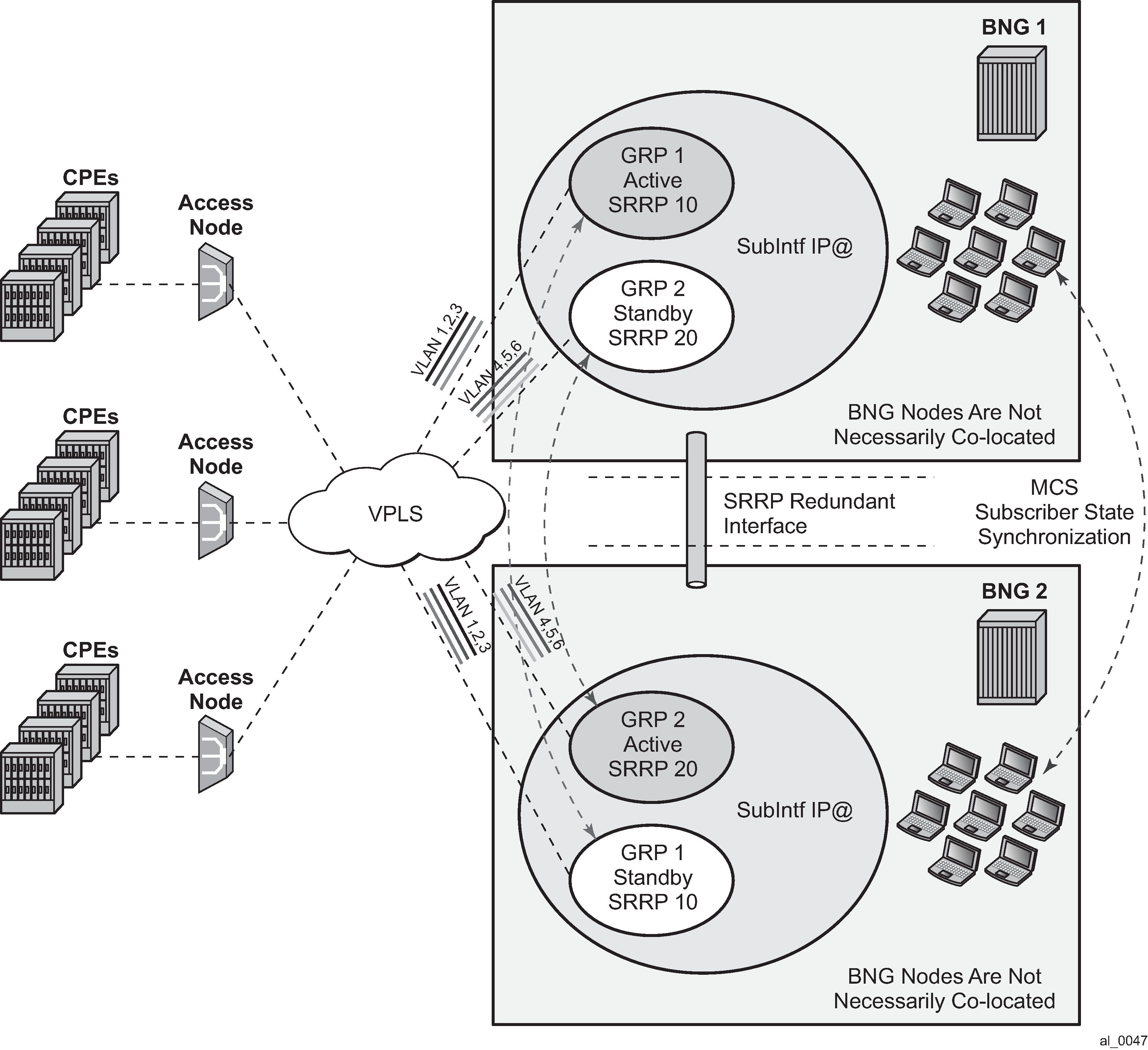
Traffic control and redundant interface
To preserve QoS and Accounting, subscriber’s traffic must flow in both directions through the multi-chassis active BNG node.
In the upstream direction, this is always true as traffic is steered to the active BNG (SRRP master state) node just by the virtue of SRRP operation.
In the downstream direction which represents bulk of traffic, SRRP cannot be relied up on to steer traffic through the active BNG (SRRP master state). This poses a problem in a very common environment where IP subnets are shared over multiple group interfaces with SRRP enabled. A particular subnet is advertised to the network side from both active and standby BNGs. Natural routing on the network side determines which BNG node receives subscriber’s traffic in the downstream direction. If the standby BNG (SRRP backup state) node receives the traffic, it cannot simply send the traffic directly to the access network where the subscriber resides by just inserting the source MAC address of the SRRP instance in the outgoing packet. This would break the operation of SRRP. Instead, the standby BNG must send the traffic to the active BNG through a redundant interface. The active BNG then forwards traffic directly to the subscriber. Source MAC address of this traffic is the MAC address of SRRP instance. This traffic shunting over the redundant interface can result in a substantial load on the link between the two BNGs.
The increase in shunted traffic can quickly become an issue if the redundant BNG nodes are not colocated. To minimize the shunt traffic, more granular routing information must be presented to the network core. This leads to more optimal routing where downstream subscriber traffic is directed toward the active BNG, without the need to cross the redundant interface. The disadvantage of this approach is that this further fragments the IP address space within the network core. In the extreme case where /32 (subscriber) IP addresses are advertised, the churn that /32s cause in the core routing can be unsustainable. In this case, routing updates in the core are triggered by subscribers coming on/off-line.
Optimal operation calls for the shunt traffic to be eliminated and at the same time, a high IP route aggregation on the network side is achieved. The existence of the shunt traffic stems from the fact that routing protocols advertise subscriber subnets into the network with no awareness of the SRRP master or backup state. To address this problem along with better aggregation of advertised subnets, two SRRP enhancements are introduced:
SRRP fate-sharing
SRRP aware routing
Both of these concepts are described in SRRP enhancement.
Traffic destined for or from the subscriber is forwarded under the condition that the subscriber-interface is operationally UP. This applies also to shunting of downstream subscriber traffic from the standby (SRRP backup state) to the active (SRRP master state) node. It is always necessary to keep the subscriber-interface operationally UP by configuring a dummy group interface with a oper-up-while-empty command under it. This is especially true for the MC-LAG which causes the messaging SAP on the STANDBY node always to be in the INIT state. In case that MSAPs are used on such group interfaces, the group interfaces would be also operationally DOWN, causing the subscriber-interface to be operationally DOWN.
Subnet assignment and advertisement - option A
A single IP subnet is used for all subscribers terminated within the redundant BNG nodes. The upside of the option A is that it offers aggregated IP addressing in the network core per pair of redundant BNG nodes. The downside is that the subscriber termination point (active BNG for the SRRP group) is hidden from the network core. Because both BNG nodes share the same IP subnet for the subscribers, the natural routing can cause downstream traffic to be sent to the standby BNG which must shunt the traffic to the active BNG. It is likely that half of the traffic is shunted over the redundant-interface with this approach. This scenario is shown in Shared subscriber IP space.
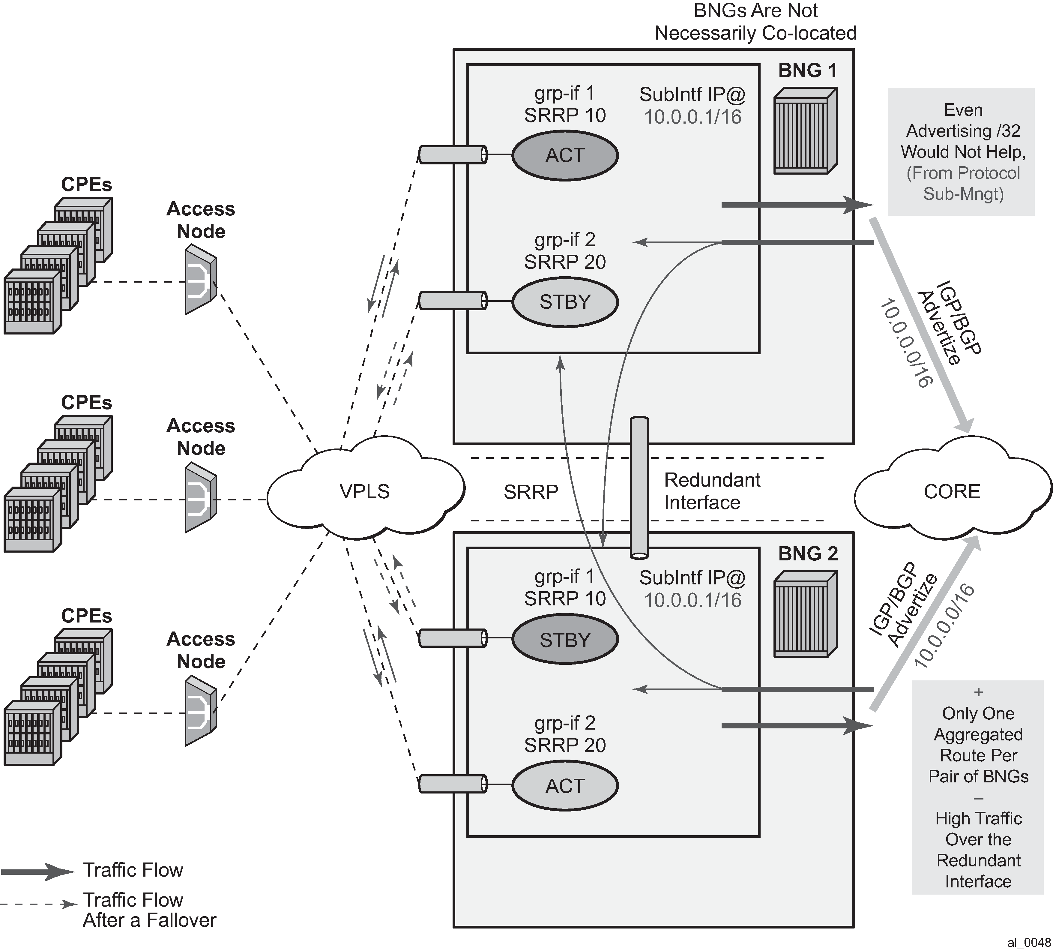
Subnet assignment and advertisement - option B
With the option B, an IP address pool (or subnet) can be allocated per group of SRRP instances that are in the SRRP master state. The routing decision on the network side is further influenced by the static increase of the metric of the advertised route on the BNG node hosting the active SRRP groups (Option B – IP subnet per active SRRP group).
This approach would cause greater IP space segmentation in the network core, but at the same time, it would indirectly provide more information about the subscriber whereabouts and therefore minimize or eliminate the shunt traffic during the normal operation. However, if an SRRP switchover occurs, the shunt traffic would ensue. The amount of the shunted traffic would depend on the scale of the failure. From the configuration displayed in Option B – IP subnet per active SRRP group, it can be concluded that:
There is no shunted traffic.
If any of the SRRP instances transitions out of the SRRP master state, traffic for an entire IP network associated with this failed SRRP instance would be shunted. The reason for this is that the advertised route metric is static and it does not follow changes in SRRP state.
Figure 29. Option B – IP subnet per active SRRP group 
MSAP considerations
As per RFC 2516, A Method for Transmitting PPP Over Ethernet (PPPoE), this has the implications on the operation of the capture SAP. In an IPoE environment, the initial DHCP traffic related to host establishment uses its native MAC of the physical port on the router. After the group interface is learned (later in the process, by RADIUS or msap-policy), the MAC address is switched to SRRP MAC address (virtual MAC). The IPoE client adapts easily to this change. On the contrary, for the correct operation of PPPoE with SRRP, the initial destination MAC address learned by the PPPoE client does not change during the lifetime of the session.
This is ensured by indirectly referencing the grp-if under the capture SAP:
config>service>vpls
    sap 1/1/1:1.* capture-sap
        track-srrp 10
    sap 1/1/1:2.* capture-sap
        track-srrp 20

config>service>vprn>
    subscriber-interface <ip-int-name>
        group-interface <ip-int-name>
            sap 1/1/1:1.1
                srrp 10
                message-path 1/1/1:1.1

    group-interface <ip-int-name>
        sap 1/1/1:2.1
            srrp 20
                message-path 1/1/1:2.1
With this approach the grp-if is nailed during the session initiation phase by referencing the SRRP instance in track-srrp statement (SRRP is a group interface-wide concept). RADIUS returned grp-if name must match the one on which referenced SRRP instance runs.
The capture SAP of the form
sap port-id:*.* capture-sap
    track-srrp X
assumes that there is only one grp-if associated with all MSAPs under this capture SAP.
A check is put in place to make sure that the MAC addresses associated with the SRRP instance is the same as the MAC address of the associated capture SAP. A log is raised if there is a discrepancy between the MAC addresses while the grp-if is operationally UP. If there is a MAC address change (user misconfiguration) then the existing PPPoE sessions time out and the new sessions fail to establish until the condition is corrected.
Unnumbered interface support
For unnumbered subscriber-interface support in PPPoE, the gateway IP address that is used to send gratuitous ARP is not available. For this reason, the system IP address is used to send gratuitous ARPs. Gratuitous ARP is used to update the Layer 2 network forwarding path toward the BNG node in the upstream direction.
The system IP address is used automatically if the subscriber interface is unnumbered.
Compatibility with MC-LAG
SRRP for PPPoE works in an environment where MC-LAG is enabled. For example, the standby MC-LAG link automatically puts the SRRP instance in a backup state and the active MC-LAG link puts the SRRP instance in a master state. It is important that the SRRP instance on the standby leg of the MC-LAG is forced into a SRRP backup state, or any other state that forces the downstream traffic to use the redundant interface.
Traffic destined for or from the subscriber is forwarded under the condition that the subscriber-interface is operationally UP. This applies also to shunting of downstream subscriber traffic from the standby (SRRP backup state) to active (SRRP master state) node. It is always necessary to keep the subscriber-interface operationally UP by configuring a dummy group interface with a oper-up-while-empty command under it. This is especially true for the MC-LAG which causes the messaging SAP on the standby node always to be in the INIT state. If MSAPs are used on such group interfaces, the group interfaces would be also operationally DOWN, causing the subscriber-interface to be operationally DOWN.
IPv6 support
Prerequisite for MC IPv6 Redundancy is to synchronize PPPoEv6 and IPoEv6 subscribers between the nodes by MCS.
In PPPoE environment, SRRP is used to refresh the forwarding path (MAC addresses) in the access aggregation network (by gratuitous ARP). SRRP ensures that the upstream traffic is steered to the active BNG node (SRRP master state). In the downstream direction, the standby BNG directs traffic over to the active BNG node via a redundant-interface.
The IPv6 functionality currently relies on IPv4 based SRRP and IPv4 based redundant-interface. In other words, IPv4 is required to run on the access side as well as on the redundant-interface.
The redundant-interface is used in the downstream direction. Traffic arriving on the network links on the standby node is shunted over to the active node over the redundant-interface. This is required to ensure consistent QoS and accounting functionality across the nodes (upstream and downstream traffic on the access links for a subscriber must traverse the same BNG node). There is no IPv6 related CLI associated with the redundant-interface.
All IPv6 subscriber traffic that arrives on the standby node in the downstream direction is automatically shunted over the IPv4 redundant-interface to the active node. When IPv6 traffic arrives over the redundant-interface on the active node, it is either PPPoEv6 encapsulated or left as plain IPoEv6 before it is forwarded to the subscriber.
In the upstream direction (AN->BNG) the behavior is the following:
PPPoEv6
On the switchover, gratuitous ARPs (gARP) is sent from the new active BNG (SRRP master state) on each VLAN. The IP address in gARP is the IPv4 gw-ip address or the system IP if there are unnumbered interfaces. This updates the Layer 2 network path with the correct SRRP MAC address.
IPoEv6
IPv4 based SRRP is used to update the Layer 2 forwarding path in the case of a switchover. A gratuitous ARP is sent in the same way as it is used for IPoE v4 hosts. Router Advertisements (RA) are not sent out in the event of the switchover.
However, the two BNG nodes share the same virtual Link Local (LL) IPv6 address. This address is used by the clients as a default-gw and only the active BNG (SRRP master state) advertises this LL address in RAs. RAs are suppressed on the standby BNG. As previously mentioned, RAs are not sent during the switchover. RAs are sent:
When the client is first established
This is how the client learns its default-gw (in PPPoE case RA can also be used for SLAAC, stateless address configuration).
As a reply to Router Solicitations messages sent by the clients
Periodically to each client
Note that RAs are unicast to each client.
Neighbor Advertisements (NA) used for address resolution are sent only from the active BNG. NA has the SRRP MAC address in the target link layer option on SRRP enabled group interfaces (on non-SRRP enabled group interfaces, NAs contains the group interface MAC address).
The LL IPv6 address must be the same on both nodes. In addition, the gw-mac address must be the same on both nodes. The IPv6 clients are not aware of the switchover and therefore they do not send NS to solicit the update of its neighbor cache with the possibly different gw-mac address.
The syntax to configure the LL address on the subscriber interface is as follows:
        config>service>ies | vprn>
            subscriber-interface <ip-int-name>
                ipv6
                    [no] link-local-address <ipv6-address>
            <ipv6-address>       : ipv6-address   - x:x:x:x:x:x:x:x
                                                    x:x:x:x:x:x:d.d.d.d
                                                     x [0..FFFF]H
                                                     d [0..255]D
Note that the current version of SRRP relies only on IPv4 routes. The connection between SRRP and IPv4 routes is done with the subnets with gw IP addresses defined under the subscriber-interfaces in the ESM context. This connection is needed so that SRRP can send Gratuitous ARP properly.
These are the cases for PPPoEv6 MC Redundancy that are supported:
unnumbered subscriber-interfaces (config>service>subscriber-interface hierarchy)
numbered IPv4 subscriber-interfaces (config>service>subscriber-interface hierarchy)
numbered IPv4 and IPv6 subscriber-interfaces (config>service>subscriber-interface and config>service>sub-if>ipv6 hierarchy)
numbered IPv6 only subscriber-interfaces (config>service>sub-if>ipv6 hierarchy) is not supported
Considerations with local DHCP server
When local DHCP server redundancy or synchronization is used, using address-range failover local | remote, in conjunction with PPPoE in multi-chassis environment, both DHCP servers must be referenced under the corresponding group interface on each node. For address-range failover access-driven configurations only one DHCP server must be referenced.
subscriber-interface <ip-int-name>
    group-interface <ip-int-name>
        dhcp
            server <local-dhcp-ip-address> <remote-dhcp-ip-address>
Otherwise, the PPPoE clients are not synchronized by MCS.
This is not the requirement in the IPoE environment. In the IPoE environment, it is enough that the DHCP server points to the IP address of the local DHCP server. If the IP lease is originally assigned by the peer DHCP server, the request for renewal is automatically forwarded to the remote DHCP server by the virtue of the IP address of the original DHCP server that is included in the renewal request.
It is necessary for the successful renewal of the IP address on the remote DHCP server, that the remote DHCP server has a valid return path back to the gi-address of the forwarder of the renewal request.
Redundant interface considerations
In PPPoE dual-chassis environment without the redundant-interface in place, SRRP aware routing should always be used. Otherwise, if the downstream traffic arrives on the standby node (SRRP backup state), it is forwarded directly to the client over the access network (assuming that the access network is operational) with the source MAC address of the group interface (instead of gw-mac). This grp-if MAC address is different from the MAC address (gw-mac) negotiated during the initial PPPoE phase, and therefore, this traffic is dropped by the client. It must be ensured that the downstream traffic is always attracted to the active node (SRRP master state) in the absence of redundancy.
IPCP address via DHCPv4 client considerations
When SRRP is in the INIT state on both ends of a multi-chassis redundant setup, such as in the case of directly connected access node failures, the PPPoE session in the BNG does not time out based on the LCP keepalives. When the IPCP address of the PPPoE session is allocated via the internal DHCPv4 client, the PPPoE session is maintained until the DHCPv4 client lease expires. The system deletes the PPPoE session and sends an accounting stop message. No link exists between the router that sends the accounting stop message and the router where the SRRP instance was last active.
Routed Central Office
Layer 3 subscriber interfaces
On regular interfaces in an IES or VPRN service, only one SAP can be associated. A group interface allows multiple SAPs to be configured as part of a single interface. All SAPs in a single group interface must be within the same port. Because broadcast is not allowed in this mode, forwarding to the subscriber is based on IP/MAC addresses information gathered by the subscriber management module and stored in the subscriber management table. These entries are based on both static and dynamic DHCP hosts. Routed Central Office (CO) must be used with standard subscriber management or enhanced subscriber management. DSLAMs are typically deployed with Ethernet interfaces.
This model is a combination of two key technologies, subscriber interfaces and group interfaces. While the subscriber interface define the subscriber subnets, the group interfaces are responsible for aggregating the SAPs.
As depicted in Subscriber interface in an IES/VPRN service, an operator can create a new subscriber interface in the IES or VPRN service. A subscriber interface allows for the creation of multiple group interfaces. The IP space is defined by the subnets of the subscriber interface’s addresses. Details of a group interface shows the details of group interface A.

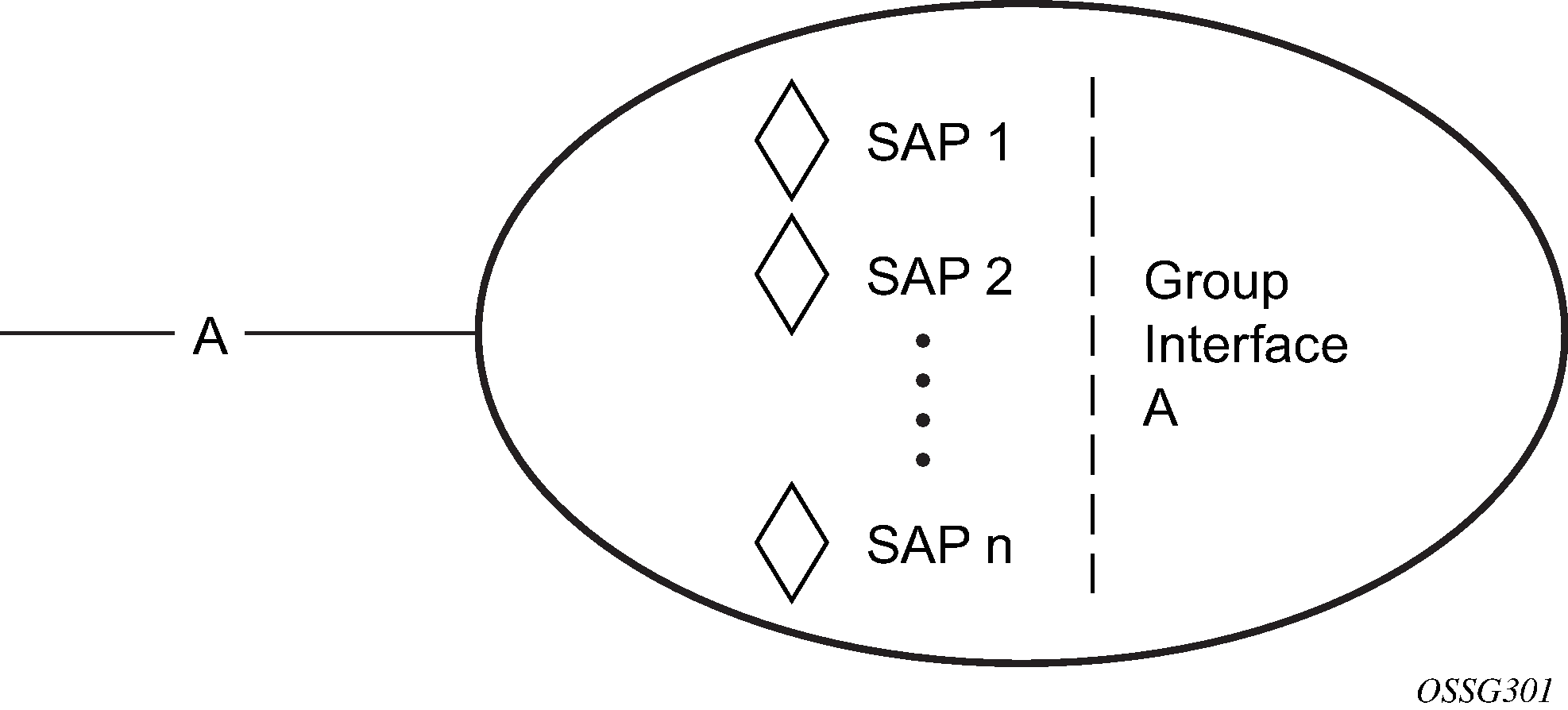
Aggregation network with direct DSLAM-BSR connection shows a network diagram where the DSLAM are connected directly to a Broadband Service Router (BSR) providing access to an IP subnet. Subscribers from multiple DSLAMs can be part of the same subnet. Note that BSR is also referred to as Broadband Network Gateway (BNG).
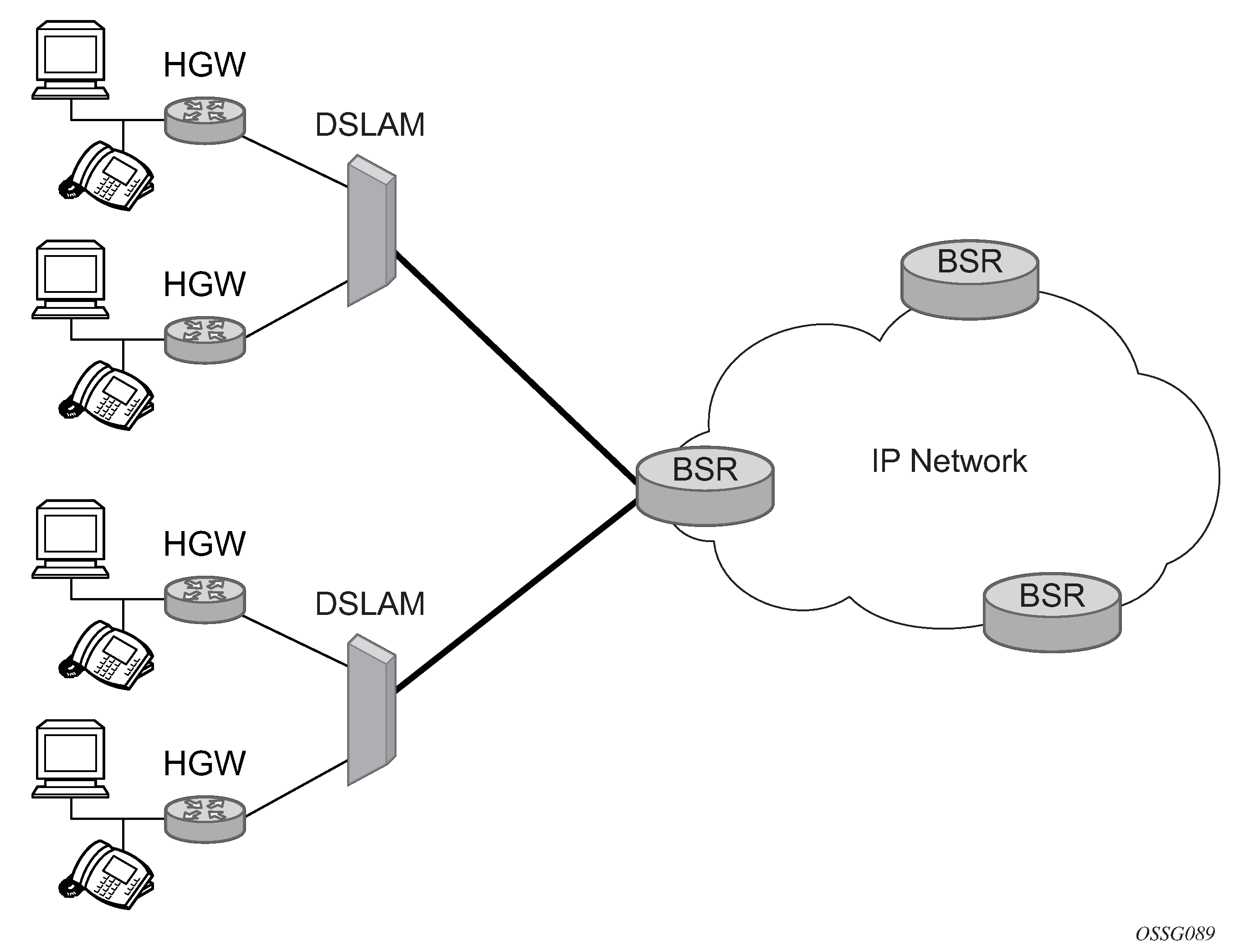
The BSR can be configured with multiple subnets, allowing subscribers to be part of a single subnet as well as providing mechanisms for re-addressing or expanding existing services without affecting existing users.
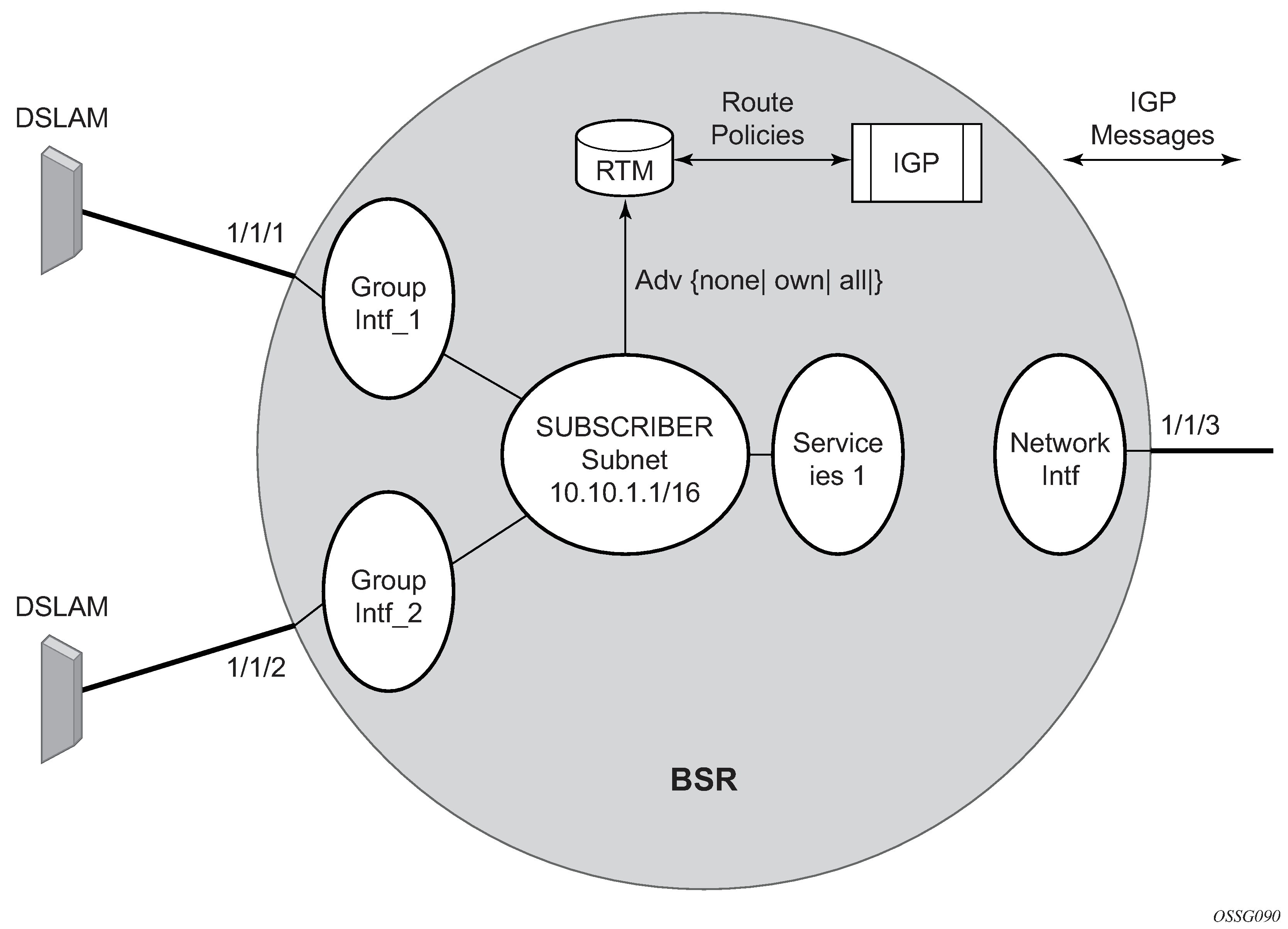
Detailed view of configurable objects related to Layer 3 subscriber interfaces shows a detailed view of a router and the configuration objects implemented to support Layer 3 subscriber interfaces.
A subscriber service is defined by an IES Service. One or more IES services can be created.
Each IES service concentrates a number of subscriber-interfaces. The operator can create multiple subscriber interfaces (represented as a subscriber subnet). A subscriber interface defines at least one subnet.
A group interface is provisioned within the subscriber interface for each DSLAM connected. All group interfaces created under the subscriber interface share the same subnet (or subnets). Group interfaces (shown as intf_1 and intf_2 in Detailed view of configurable objects related to Layer 3 subscriber interfaces) are configured as unnumbered and are associated with the subscriber-interface under which they are configured.
SAPs can be configured under the group interface. In a VLAN-per-DSLAM model only, one SAP per group interface is needed, while in the VLAN-per-subscriber model, a subscriber of the DSLAM requires its own SAP. All SAPs on a group interface must be on the same physical port or LAG.
The individual features related to subscribers, such as DHCP relay, DHCP snooping and anti-spoofing filters, are enabled at group interface level. For a Routed CO model of subscriber management, and when enhanced subscriber management (if sub-sla-mgmt is configured). Then, hashing is based on an internally assigned subscriber-ID. Having a unique subscriber ID configured in CLI ensures that each subscriber is assigned a unique internal subscriber ID.
It is assumed that individual end-user devices (further referred to as subscriber hosts) get their IP address assigned through either DHCP or static configuration. The management of individual subscriber hosts (such as creation, queue allocation, and so on) is performed by ESM.
The operator can provision how the system advertises routes. While most deployments advertise the full subnet it is possible to have the system advertise only the active, discovered or static host routes.
The distribution of this information into routing protocols is driven by import/export route policies configured by the operator.
DHCP interactions
The DHCP relay process has been enhanced to record incoming DHCP discover and request messages. Because forwarding to the SAPs is done by the information in the subscriber management table and multiple SAPs are allowed in one interface it was impossible to know which SAP is used to forward the DHCP replies. The node maintains a cache of the DHCP requests. The cache can be viewed using the tools>dump>router>dhcp>group-if-mapping command. The cache holds an entry for 30 seconds. If an ACK/NAK packet was not received from the server within the timeout the node discards the cache entry. The node can use the Option 82 circuit-id field as part of the temporary host entry. If used, the ACK must contain the same circuit-id field in Option 82 to be found in the cache only if the match-circuit-id is specified at the DHCP level of the group- interface. When the match-circuit-id command is enabled a check is performed for option 82 circuit-id.
Routed CO for IES service
The routed CO model depends on subscriber management to maintain the subscriber host information. To create a group interface the operator must first create a subscriber interface within the service (config>service>ies>subscriber-interface ip-int-name). The subscriber interface maintains up to 256 subscriber subnets and is configured with a host address for each subnet.
When a DHCP ACK is received the IP address provided to the client is verified to be in one of the subscriber subnets associated with the egress SAP. When DHCP snooping is enabled for regular IES interfaces the same rule applies.
The subscriber interface is an internal loopback interface. The operational state is driven from the child’s group interface states and the configuration of an address in the RTM.
The group interface is an unnumbered interface. The interface is operationally up if it is in the no shutdown state and if at least one SAP has been defined and is up and the parent subscriber interface is administratively up. The first SAP defined determines the port for the group interface. If the user attempts to define a subsequent SAP that is on a different port results in an error. When the subscriber-interface or the group interface is in a shut down state no packets are delivered or received to or from the subscriber hosts but the subscriber hosts, both dynamic and static, are maintained based on the lease time.
In the routed CO model, the router acts as a DHCP relay agent and also serves as the subscriber- identification agent. The DHCP actions are defined in the group interface. All SAPs in that interface inherit these definitions. The group interface DHCP definition are a template for all SAPs.
Lease-populate is enabled by default with the number-of-entries set to 1. This enables DHCP lease state for each SAP in the group interface.
Because the group interface can aggregate subscribers in different subnets a GI address must be defined for the DHCP relay process. The address must be in one of the host addresses defined for the subscriber interface. The GI address can be defined at the subscriber interface level which causes all child group interface to inherit that route. The GI address can then be overridden at the group interface level. A GI address must be defined in order for DHCP relay to function.
Because of the nature of the group interface, local-proxy-arp, as well as arp-populate, should be enabled. This would allow the system to respond to subscriber ARP requests if the ARP request contains an IP address which is in the same subnet as one of the subscriber interface subnets.
When an authentication policy is specified for a SAP under a group interface, DHCP intercepts DHCP discover messages for RADIUS authentication. If the system is a DHCP-relay defined in a group interface and the GI address was not configured, the operational state of DHCP is down.
Routed CO for VPRN service
Much like in Routed CO for IES service, the Routed CO model for VPRN depends on subscriber management to maintain the subscriber host information. To create a group interface, the operator must first create a subscriber interface in the config>service>vprn context. The subscriber interface can maintain up to 256 subscriber subnets and can be configured with a host address for each subnet. The host IP address can be installed as a result of both relaying to a DHCP server and proxy to a RADIUS server. In both cases the host IP address must be in the subnet defined by the VPRN’s subscriber interface.
Basic subscriber management is allowed only in a subscriber/SAP model and can be used only in a dedicated VPRN architecture. A RADIUS service selection (using Managed SAPs) requires Enhanced Subscriber Management. The subscriber interface’s subnets are allowed to be advertised to both IGPs and BGP within a VPRN.
When an authentication policy is specified for a group interface, DHCP snooping must be enabled to intercept DHCP discover and renew messages for RADIUS authentication. Subscriber management RADIUS extensions are allowed if the operator chooses to have the RADIUS server return the subscriber identification, subscriber profile and sla-profile strings using RADIUS.
The node can be defined with both a DHCP relay or proxy function. If the user configures a DHCP relay, the local-proxy-server command enables DHCP split leases. In that configuration the node provides the configured DHCP lease to the client using either RADIUS or the real DHCP server as the source of the IP address to be provided.
The RADIUS server can send a Change of Authorization (CoA) message containing the DHCP FORCERENEW VSA which prompts the local-proxy-server to send a FORCERENEW message to the client. The node ACKs when the FORCERENEW messages has been sent, regardless of whether the subscriber responds. If the client fails to respond or if a new session cannot be established because of resource management issues or otherwise the node must respond with a NACK to the RADIUS server.
If the CoA message contains an IP address that is different than the configured IP address (when RADIUS was providing IP addresses) the node must send a FORCERENEW message to the client and NAK the request and provide a new IP address. If the node fails to receive a request, the CoA is ACK’d when the FORCERENEW message has been sent.
The operational state of group and subscriber interfaces are dependent on the state of active SAPs. A group interface can become operationally up only if at least one SAP is configured and is in an operationally up state. A subscriber interface becomes operationally up if at least one group interface is operationally up or the associated wholesale forwarding interface is operationally up. This ensures that, in a failure scenario that affects all group interfaces in a specific subscriber subnet, the node stops advertising the subnet to the network. The SRRP state affects this behavior as well and can cause the subnet to be removed if all group interfaces (and SRRP instances) are in backup state.
Wholesale retail Routed CO
VPRN Routed CO allows a provider to resell wholesaler services (from a carrier) while providing direct DSLAM connectivity. An operator can create a VPRN service for the retailer and configure the access from subscribers as well as to the retailer network. Any further action acts as if the VPRN is a standalone router running the Routed CO model. All forwarding to these servers must be done within the VPRN service. The operator can leak routes from the base routing instance. In this model, the operator can use RADIUS for subscriber host authentication, DHCP relay and DHCP proxy. This provides maximum flexibility to the retailer while minimizing the involvement of the wholesaler. Access cannot be shared among retailers unless a subscriber SAP is used. This requires that the wholesaler maintain a different access node (DSLAM) for each retailer that does not scale well. The wholesale retail model described in this section overcomes these limitations.
Wholesale retail model
In the wholesale retail model (Wholesale retail model), the wholesaler instance connections that are common to the access nodes are distributed to many retail instances. A subscriber host attached to an access node connected in the wholesaler service can be instantiated in a retail service and obtain IP addresses from the retailers address space. The service context of the retailer is determined during the subscriber host authentication phase (for example, by the Alc-Retail-Serv-Id attribute or the Alc-Retail-Serv-Name attribute in RADIUS or the retail-service-id CLI command in the local user database).
Upstream subscriber traffic ingresses into the wholesaler instance and after identification is then forwarded into the retail instance. The reverse occurs for traffic in the downstream direction.

In a wholesale retail model, two subscriber interfaces must be configured and linked together: one in the wholesale VPRN and one in the retail service.
The wholesale subscriber interface defines the IP subnets and host specific configuration parameters for subscriber hosts belonging to the wholesaler. There are associated group interfaces that contain the SAPs which connect to the access nodes.
The retail subscriber interface defines the IP subnets and host specific configuration parameters for subscriber hosts belonging to the retailer. The retail subscriber interface is linked to a wholesale subscriber interface for forwarding by explicit configuration. There are no associated group interfaces.
For example:
config>service
        vprn 1000 customer 1 create
            subscriber-interface "sub-int-ws-1" create
            # wholesale subscriber interface
                --- snip ---
                group-interface "group-int-1-1" create
                    --- snip ---
                    sap 1/1/1:1 create
                        --- snip ---
                    exit
                exit
            exit
        exit


       vprn 1001 customer 1 create
            subscriber-interface "sub-int-rt-1" fwd-service 1000    \\
                            fwd-subscriber-interface "sub-int-ws-1" create
            # linked retail subscriber interface
                --- snip ---
            exit
        exit
A retail subscriber interface can be linked to a single wholesale subscriber interface and context only. Subscriber interface chaining (linking a retail subscriber interface to another retail subscriber interface) is not supported. Multiple retail subscriber interfaces belonging to different retail contexts can be associated with a single wholesale subscriber interface. When a retail subscriber interface is linked to a wholesale context, all other retail subscriber interfaces from the same retailer must be linked to the same wholesale context.
Configuration and applicability
As described in the previous section, the wholesale retail model is provisioned with the linking of a subscriber interface in a retail service to a subscriber interface in the wholesale VPRN service.
Because a retail subscriber interface does not have a group interface context, some group interface-specific CLI parameters such as to configure dhcp relay are made available at the retail subscriber interface level. Other CLI parameters such as to provision RADIUS or local user database authentication are configured at the wholesale subscriber or group interface and apply to both wholesale and retail subscriber hosts.
The DHCP lease-populate configuration is special in wholesale retail as it is configured in both wholesale and retail context. The lease-populate value in the wholesale group-interface dhcp context controls the per SAP limits while the lease-populate value configured in the retail subscriber interface dhcp context controls the limits for the retailer subscriber interface. Both limits must be satisfied before a new subscriber host can be instantiated.
The sample configurations below enable dual-stack IPoE devices to connect to wholesale service VPRN 4000 and retail service VPRN 4001. Hosts connected in VPRN 4000 get their IP address assigned from RADIUS, therefore the proxy server configuration. Hosts connected in VPRN 4001 get their IP address from a DHCP server, therefore the DHCP relay configuration.
Only the service configurations are shown. They have to be completed with authentication policies and subscriber management configuration such as radius-server-policies, sub- and sla-profiles, and so on.
Sample configuration
Wholesale VPRN service:
config>service
        vprn 4000 customer 1 create
            autonomous-system 64500
            route-distinguisher 64500:4000
            auto-bind-tunnel
                resolution-filter
                    ldp
                    rsvp
                exit
                resolution filter
            exit
            vrf-target target:64500:4000
            subscriber-interface "sub-int-1" create
                address 10.10.1.254/24
                address 10.10.2.254/24
                ipv6
                    delegated-prefix-len variable
                    subscriber-prefixes
                        prefix 2001:db8:a:100::/56 wan-host
                        prefix 2001:db8:a001::/48 pd
                    exit
                exit
                group-interface "group-int-1" create
                    ipv6
                        router-advertisements
                            no shutdown
                        exit
                        dhcp6
                            proxy-server
                                no shutdown
                            exit
                        exit
                    exit
                    arp-populate
                    dhcp
                        proxy-server
                            emulated-server 10.10.1.254
                            no shutdown
                        exit
                        lease-populate 100
                        no shutdown
                    exit
                    authentication-policy "auth-policy-1"
                    sap 1/1/4:1201.27 create
                        sub-sla-mgmt
                            sub-ident-policy "sub-ident-1"
                            multi-sub-sap 100
                            no shutdown
                        exit
                    exit
                exit
            exit
            no shutdown
        exit
Sample configuration
Retail VPRN service:
config>service>
        vprn 4001 customer 1 create
            autonomous-system 64501
            route-distinguisher 64500:4001
            auto-bind-tunnel
                resolution-filter
                    ldp
                    rsvp
                exit
                resolution filter
            exit
            vrf-target target:64500:4001
            interface "int-loopback-1" create
                address 192.0.2.5/32
                ipv6
                    address 2001:db8::5/128
                exit
                loopback
            exit
            subscriber-interface "sub-int-rt-4000-1" fwd-service 4000 fwd-subscriber-
interface "sub-int-1" create
                address 10.10.11.254/24
                address 10.10.12.254/24
                dhcp
                    server 192.0.2.4
                    lease-populate 100
                    gi-address 10.10.11.254
                    no shutdown
                exit
                ipv6
                    subscriber-prefixes
                        prefix 2001:db8:b:100::/56 wan-host
                        prefix 2001:db8:b001::/48 pd
                    exit
                    dhcp6
                        relay
                            source-address 2001:db8::5
                            server 2001:db8::4
                            no shutdown
                        exit
                    exit
                    router-advertisements
                        no shutdown
                    exit
                exit
            exit
            no shutdown
        exit
The wholesale retail model applies to all IPoE, PPPoE PTA, IPv4 and IPv6 host types.
The wholesale service type must be VPRN. For IPoEv4 hosts, the retail service type must be a VPRN. For all other host types, the retail service type can be IES or VPRN.
Multicast-per-host replication can be enabled without support for multi-chassis redundancy.
The wholesale retail model can be deployed in combination with managed SAPs.
Overlapping subscriber subnets and prefixes in retail VPRN services associated with the same wholesale forwarding service are supported for PPPoE (IPv4 and IPv6) and IPoE (IPv4 and IPv6). This support is enabled by configuring private retail subnets on the retail subscriber interface. Private retail subnets are supported when multi-chassis redundancy is needed.
Hub-and-spoke forwarding
In some cases, hub-and-spoke-type forwarding is necessary for the retailer’s VPRN. When the retailer expects all subscriber traffic to reach its router (for accounting, monitoring, wiretapping, and so on) normal best-hop behavior within the retailer VPRN is wanted. Any subscriber-to-subscriber traffic is forwarded within the VPRN preventing the retailer from receiving these packets. To force all subscriber packets to the retailer network, a hub-and-spoke topology is defined: type subscriber-split-horizon. It can be used to force all subscriber traffic (upstream) to the retailer’s network. The system requires that the operator shut down the VPRN service to enable this flag.
With retail VPRN type configured to subscriber-split-horizon, routes learned from MBGP, IGP through a regular interface, static routes through regular interfaces and locally attached regular interface routes are considered hub routes and are used for upstream traffic forwarding. Subscriber subnets cannot be used for upstream traffic forwarding. Downstream traffic uses routes in both hub and spoke routing instances.
Wholesale retail – hub-and-spoke forwarding shows user-to-user traffic forwarding for both retail VPRN types: regular and subscriber-split-horizon.

Hub-and-spoke forwarding can also be used in combination with wholesale unicast RPF (uRPF) check. The uRPF is performed on upstream traffic on spoke routes (subscriber subnets) and the forwarding uses hub routes only.
Static hosts in wholesale retail
-
In IPv4 static hosts with numbered retailer subscriber interface without private retail subnets or allow unmatching subnets, host addresses are automatically matched with the retailer subnet, and IP routes to hosts are created in the retailer VPRN.
-
In IPv4 static hosts with retailer subscriber interface with unnumbered addresses, private retail subnets, or allows unmatching subnets, to create IP routes to hosts in the retailer VPRN, manual configuration of route export from wholesale to retail is required. On wholesale VPRN, only numbered subscriber interfaces are supported.
-
In IPv6 static hosts, the retail-svc-id must be configured to specify the retailer VPRN.
Routed subscriber hosts
A routed subscriber host associated route, as shown in Routed subscriber hosts, is a global routable subnet/prefix behind a routed CPE or Home Gateway. The routed CPE is identified in the BNG as an ESM subscriber host: QoS, accounting and anti-spoofing is enforced per CPE. The associated routes are installed in the BNG route table with next-hop pointing to the routed subscriber host’s WAN address.
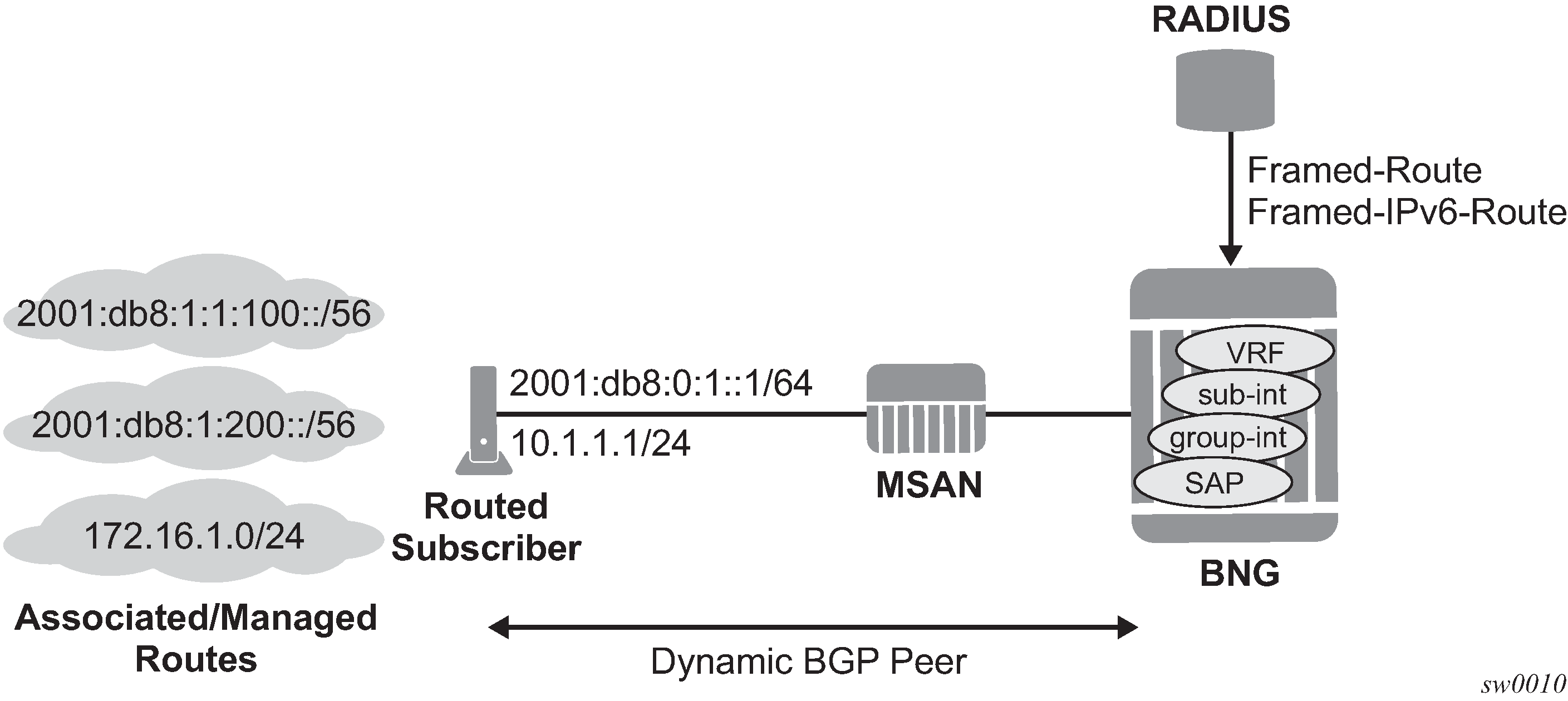
Routed subscriber host associated routes are supported on IES/VPRN subscriber interfaces in a routed CO configuration. To put a SAP or MSAP in routed subscriber mode, the anti-spoof type for the SAP or MSAP must be configured to nh-mac:
configure
    service ies/vprn <service-id>
        subscriber-interface <ip-int-name>
            group-interface <ip-int-name>
                sap <sap-id>
                           anti-spoof nh-mac

configure
    subscriber-mgmt
        msap-policy <msap-policy-name>
            ies-vprn-only-sap-parameters
                anti-spoof nh-mac
Routes associated with a routed subscriber host (known as managed routes) can be learned in the following ways:
managed routes configuration for a static host
the RADIUS or NASREQ authentication [22] Framed-Route and [99] Framed-IPv6-Route attributes
advertised using an ESM dynamic BGP peer
learned using a RIP listener neighbor (IPv4 routes only)
the IPv6 Prefix Delegation prefix as a managed route
Static configured IPv4 managed route
The routes associated with a static host are populated in the routing table as ‟Remote Managed” routes. Up to sixteen managed routes can be configured for a static host. The following examples show static IPv4 managed route configurations
MD-CLI
[ex:/configure service ies subscriber-interface group-interface sap]
[ex:/configure service vprn subscriber-interface group-interface sap]
A:admin@node-2#
    static-host {
        ipv4 10.1.1.20 mac 00:00:00:00:00:00 {
            sub-profile "sub-profile-1"
            sla-profile "sla-profile-1"
            subscriber-id {
                string "static-host-1"
            }
            managed-route 172.20.1.0/24 {
                metric 10
                preference 5
                tag 100
}
            ...
managed-route 172.20.16.0/24 {
                metric 10
                preference 5
                tag 100
}
        }
    }
classic CLI
config>service>ies>sub-if>grp-if>sap#
config>service>vprn>sub-if>grp-if>sap#
    static-host ip 10.1.1.20 create
        sla-profile "sla-profile-1"
        sub-profile "sub-profile-1"
        subscriber "static-host-1"
        managed-routes
            route-entry 172.20.1.0/24 create
                metric 10
                preference 5
                tag 100
            exit
...
route-entry 172.20.16.0/24 create
                metric 10
                preference 5
                tag 100
            exit
        exit
        no shutdown
exit
Use the following command to display the managed routes associated with a routed subscriber host.
show service id service-id static-host detailStatic configured IPv6 managed route
The routes associated with a static host are populated in the routing table as ‟Remote Managed” routes. Up to sixteen managed routes can be configured for a static host. The following examples show static IPv6 managed route configurations.
MD-CLI
[ex:/configure service ies subscriber-interface group-interface sap]
[ex:/configure service vprn subscriber-interface group-interface sap]
A:admin@node-2#
    static-host {
        ipv6 2001::1/128 mac 00:00:00:00:00:00 {
            sub-profile "sub-profile-1"
            sla-profile "sla-profile-1"
            subscriber-id {
                string "static-host-1"
            }
            managed-route 2000::/56 {
                metric 10
                preference 5
                tag 100
            }
            ...
            managed-route 3000::/56 {
                metric 10
                preference 5
                tag 100
            }
        }
    }
classic CLI
config>service>ies>sub-if>grp-if>sap#
config>service>vprn>sub-if>grp-if>sap#
    anti-spoof nh-mac
    static-host ip 2001::1/128 create
        sla-profile "sla-profile-1"
        sub-profile "sub-profile-1"
        subscriber "static-host-1"
        managed-routes
        route-entry 2000::/56 create
            metric 10
            preference 5
            tag 100
        exit
          ...
        route-entry 3000::/56 create
            metric 10
            preference 5
            tag 100
        exit
exit
no shutdown
exit
Use the following command to display the managed routes associated with a routed subscriber host.
show service id service-id static-host detailCPE connectivity check for managed routes
Verify the reachability of managed routes using CPE connectivity checks, which periodically send ICMP pings. If the ping fails a specified number of sequential times, the managed route is withdrawn, or parameters of the route (metric, preference, or tag) are changed until the next successful ping.
Unlike the CPE connectivity check for static routes, the CPE connectivity check for managed routes supports the ping destination address within the managed route subnet to check the reachability of a specific address (for example, a LAN interface of the CPE) within the managed route. To avoid circular references between the ping and the managed route, a host route toward the ping destination address is installed in the routing table.
ESM dynamic BGP peering
In enterprise IP VPNs, BGP is often used to exchange routing information, for example between headquarter and branch offices. ESM dynamic BGP peering is needed when a residential access connection provides IP connectivity to the enterprise router.
An ESM dynamic BGP peer setup is automatic when a BGP peering policy attribute is received during RADIUS authentication of a routed subscriber host. The BGP peer is torn down and the associated routes removed from the routing table when the subscriber host is removed from the system (for example, because of a lease timeout or log out).
An ESM dynamic BGPv4 peer supports the IPv4 address family to exchange IPv4 routes and an ESM dynamic BGPv6 peer supports the IPv6 address family to exchange IPv6 routes. When both IPv4 and IPv6 routes must be exchanged, dual-stack routed subscriber sessions require two dynamic BGP peers, one for each address family.
ESM dynamic BGP peering is supported for routed subscriber hosts terminated in a VPRN service and is not supported for hosts terminated in an IES service. ESM dynamic BGP peering is supported in a wholesale and retail deployment.
The BGP learned routes scaling is limited by the BGP scaling limits. The routes learned by a dynamic BGP peer are populated in the routing table as remote BGP routes.
Configuring ESM dynamic BGPv4 peering
Pre-requisites:
Enable subscriber management in the VPRN service.
Configure anti-spoof nh-mac in the group interface SAP or MSAP policy, with urpf-check optionally configured in the group interface to compensate for IP anti-spoofing not being enabled.
An ESM dynamic BGPv4 peer is established for a routed subscriber host if the 26.6527.55 Alc-BGP-Policy VSA returned in a RADIUS Access-Accept message contains the name of a local configured BGP peering policy and an ESM dynamic peer group is configured in the VPRN BGP context, as shown in the following classic CLI example.
config>subscr-mgmt
    bgp-peering-policy "bgpv4-policy-1" create
        local-address 10.3.2.254
        local-as 65536
        peer-as 65501
        type external
    exit

config>service>vprn
    bgp
        group "esm-dyn-peer-group-1" esm-dynamic-peer
        exit
        no shutdown
    exit
The following example shows the MD-CLI equivalent.
[pr:/configure subscriber-mgmt]
    bgp-peering-policy "bgpv4-policy-1" {
        local-address 10.3.2.254
        peer-as 65501
        type external
        local-as {
            as-number 65536
        }
    }

[pr:/configure service vprn "submgmt-vprn-2000"]
    bgp {
        group "esm-dyn-peer-group-1" {
            admin-state enable
            static-group false
        }
    }
The subscriber host IPv4 address is used as the BGP peer IP address.
The local address can be the subscriber interface IPv4 address (single hop BGP peer) or a loopback interface IPv4 address (multi-hop BGP peer).
See BGP peering parameters for more information about how the other BGP peering parameters can be specified and Import and export policies for ESM dynamic BGP peers for more information about route policies.
To verify that an ESM dynamic BGPv4 peer is correctly installed, use the following show commands:
show service id service-id ipoe session detail
show service id service-id ppp session detail
Example output:
Bgp Peering Policy      : bgpv4-policy-1
Bgp Peer Status         : installed
To verify the state of an ESM dynamic BGPv4 peer, use the show router router-instance bgp summary command.
Configuring ESM dynamic BGPv6 peering
Pre-requisites:
Enable subscriber management in the VPRN service.
Configure anti-spoof nh-mac in the group-interface sap or msap-policy ies-vprn-only-sap-parameters context, with ipv6 urpf-check optionally configured at the group-interface to compensate for IP anti-spoofing not being enabled.
An ESM dynamic BGPv6 peer is established for a routed subscriber host if the 26.6527.208 Alc-BGP-IPv6-Policy VSA returned in a RADIUS Access-Accept message contains the name of a local configured BGP peering policy and an ESM dynamic peer group is configured in the VPRN BGP context, as shown in the following classic CLI example.
config>subscr-mgmt
    bgp-peering-policy "bgpv6-policy-1" create
        local-address 2001:db8:b002:201::1
        local-as 65536
        peer-as 65501
        type external
    exit

config>service>vprn
    bgp
        group "esm-dyn-peer-group-1" esm-dynamic-peer
        exit
        no shutdown
    exit
The following example shows the MD-CLI equivalent.
[pr:/configure subscriber-mgmt]
    bgp-peering-policy "bgpv6-policy-1" {
        local-address 2001:db8:b002:201::1
        peer-as 65501
        type external
        local-as {
            as-number 65536
        }
    }

[pr:/configure service vprn "submgmt-vprn-2000"]
    bgp {
        group "esm-dyn-peer-group-1" {
            admin-state enable
            static-group false
        }
    }
The subscriber host IPv6 WAN address is used as the BGP peer IP address. Both SLAAC and DHCPv6 IA_NA addresses are supported.
For a SLAAC host, the BGP mode on the subscriber side must be active, that is the router at the subscriber premises should initiate the BGP TCP connection, such that the BNG can snoop the TCP SYN and derive the /128 Global Unicast Address of the SLAAC host as the BGP peer address.
ESM dynamic BGP peering is not supported for a DHCPv6 IA_PD host.
The local address can be the subscriber interface IPv6 address (single hop BGP peer) or a loopback interface IPv6 address (multi-hop BGP peer).
See BGP peering parameters for more information about how to configure other BGP peering parameters and Import and export policies for ESM dynamic BGP peers for more information about route policies.
To verify that an ESM dynamic BGPv6 peer is correctly installed, use the following show commands.
show service id service-id ipoe session detail
show service id service-id ppp session detail
Example output:
IPv6 Bgp Peering Policy : bgpv6-policy-1
IPv6 Bgp Peer Status    : installed
To verify the state of an ESM dynamic BGPv6 peer, use the show router router-instance bgp summary command.
BGP peering parameters
ESM dynamic BGP peering parameters can be specified from multiple sources:
Use BGP peering parameters returned in RADIUS VSAs; see T1 dynamic BGP peering RADIUS VSAs and RADIUS Attributes Reference Guide for more details.
If not available from RADIUS, use BGP peering parameters configured in the bgp-peering-policy.
If not configured in the bgp-peering-policy, use BGP peering parameters configured for the esm-dynamic-peer group.
If not configured in the esm-dynamic-peer group, use the BGP peering parameters configured in the VPRN service BGP CLI context.
If not configured in the VPRN service BGP CLI context, use the defaults.
| Attribute-ID | Attribute name | Description |
|---|---|---|
26-6527-55 |
Alc-BGP-Policy |
Mandatory attribute to set up a dynamic BGP peer. References a BGP peering policy configured in the configure subscriber-mgmt bgp-peering-policy CLI context. |
26-6527-208 |
Alc-BGP-IPv6-Policy |
|
26-6527-56 |
Alc-BGP-Auth-Keychain |
Optional attribute reference for a keychain configured in the configure system security keychain CLI context. |
26-6527-209 |
Alc-BGP-IPv6-Auth-Keychain |
|
26-6527-57 |
Alc-BGP-Auth-Key |
Optional attribute for the MD5 authentication key used between BGP peers for BGP session establishment. |
26-6527-210 |
Alc-BGP-IPv6-Auth-Key |
|
26-6527-58 |
Alc-BGP-Export-Policy |
Optional attribute reference for a pre-configured BGP export routing policy. |
26-6527-211 |
Alc-BGP-IPv6-Export-Policy |
|
26-6527-59 |
Alc-BGP-Import-Policy |
Optional attribute reference for a pre-configured BGP import routing policy. |
26-6527-212 |
Alc-BGP-IPv6-Import-Policy |
|
26-6527-60 |
Alc-BGP-PeerAS |
Optional attribute for the Autonomous System number for the remote peer. |
26-6527-213 |
Alc-BGP-IPv6-PeerAS |
Import and export policies for ESM dynamic BGP peers
The import and export policies used for the ESM dynamic BGP peer are determined in the following priority order:
Use import or export policies returned in RADIUS VSAs. These are appended to the policies configured in the bgp-peering-policy. A single import and a single export policy can be returned from RADIUS. A maximum of 15 policies can be active per peer. When 15 policies are configured in the bgp-peering-policy, the last policy is replaced with the RADIUS returned policy.
If not available from RADIUS and not configured in the bgp-peering-policy, use the policies configured in the esm-dynamic-peer group.
If not configured in the esm-dynamic-peer group, use the policies configured in the VPRN service BGP CLI context.
To display the BGP learned routes associated with a routed subscriber host, use the BGP show commands; for example: show router router-instance bgp neighbor ip-address received-routes.
Fast failure detection for ESM dynamic BGP peers using BFD
BGP peer failure detection is by default based on the keep-alive and hold time. For cases where fast failure detection is needed, a BFD session can be used to control the operational state of the BGP peer. Fast failure detection for ESM dynamic BGP peers using BFD is supported for IPoE and PPPoE subscribers. It is not supported for L2TP LNS subscribers.
BFD for ESM dynamic BGP peers is enabled in the bgp-peering-policy in classic CLI.
config>subscr-mgmt
    bgp-peering-policy "bgpv4-policy-1" create
        bfd-enable
        local-address 10.3.2.254
        local-as 65536
        peer-as 65501
        type external
     exit
BFD for ESM dynamic BGP peers is enabled in the BGP peering policy in MD-CLI.
[pr:/configure subscriber-mgmt]
    bgp-peering-policy "bgpv4-policy-1" {
        bfd-liveness true
        local-address 10.3.2.254
        peer-as 65501
        type external
        local-as {
            as-number 65536
        }
    }
The parameters for the BFD sessions must be configured on the group interface or retail subscriber interface in classic CLI.
config>service>vprn>sub-if>grp-ifconfig>service>vprn>sub-if
    bfd 100 receive 100 multiplier 3
    ipv6
        bfd 100 receive 100 multiplier 3
    exit
The parameters for the BFD sessions must be configured on the group interface or retail subscriber interface in MD-CLI.
[pr:/configure service vprn "submgmt-vprn-2000" subscriber-interface "sub-int-1" group-interface "group-int-1-1"]
    ipv4 {
        bfd {
            admin-state enable
            transmit-interval 100
            receive 100
            multiplier 3
        }
    }

    ipv6 {
        bfd {
            admin-state enable
            transmit-interval 100
            receive 100
            multiplier 3
        }
    }
The BFD session is always established as a single hop BFD session and therefore fast-failure detection using BFD works for single hop ESM dynamic BGP peers only. The local address for the BGP peer must be a local IPv4 or IPv6 address configured on the subscriber interface.
To verify the state of the BFD session, use the show commands in the following output examples:
A:pe2# show router 2000 bfd session
===============================================================================
Legend:
  Session Id = Interface Name | LSP Name | Prefix | RSVP Sess Name | Service Id
  wp = Working path   pp = Protecting path
===============================================================================
BFD Session
===============================================================================
Session Id                                        State      Tx Pkts    Rx Pkts
  Rem Addr/Info/SdpId:VcId                      Multipl     Tx Intvl   Rx Intvl
  Protocols                                        Type     LAG Port     LAG ID
  Loc Addr                                                             LAG name
-------------------------------------------------------------------------------
group-int-1-1                                        Up      3077793    3077716
  10.3.2.201                                          3          100        100
  bgp                                               iom          N/A        N/A
  10.3.2.254
group-int-1-1                                        Up      2988250    2988469
  2001:db8:b002:201::aaa:1                            3          100        100
  bgp                                               iom          N/A        N/A
  2001:db8:b002:201::1
-------------------------------------------------------------------------------
No. of BFD sessions: 2
===============================================================================

A:pe2# show router 2000 bfd session dest 2001:db8:b002:201::aaa:1 src 2001:db8:b002:201::1
===============================================================================
BFD Session
===============================================================================
Remote Address : 2001:db8:b002:201::aaa:1
Local Address  : 2001:db8:b002:201::1
Admin State    : Up                       Oper State       : Up
Protocols      : bgp
Rx Interval    : 100                      Tx Interval      : 100
Multiplier     : 3                        Echo Interval    : 0
Recd Msgs      : 2988898                  Sent Msgs        : 2988679
Up Time        : 2d 16:46:10              Up Transitions   : 1
Down Time      : None                     Down Transitions : 0
                                          Version Mismatch : 0
Forwarding Information
Local Discr    : 23                       Local State      : Up
Local Diag     : 0 (None)                 Local Mode       : Async
Local Min Tx   : 100                      Local Mult       : 3
Last Sent      : 08/23/2021 08:18:43      Local Min Rx     : 100
Type           : iom
Remote Discr   : 19                       Remote State     : Up
Remote Diag    : 0 (None)                 Remote Mode      : Async
Remote Min Tx  : 100                      Remote Mult      : 3
Remote C-flag  : 1
Last Recv      : 08/23/2021 08:18:43      Remote Min Rx    : 100
===============================================================================
===============================================================================
The following events are generated for a BFD protected ESM dynamic BGP peer.
ESM dynamic BGP peer established:
2602 2021/08/20 15:32:32.609 UTC MINOR: BGP #2019 vprn2000 Peer 2:
2001:db8:b002:201::aaa:1 "(ASN 65501) VR 2: Group esm-dyn-peer-group-1: Peer
2001:db8:b002:201::aaa:1: moved into established state"
BGP added as protocol to track by the BFD session:
2603 2021/08/20 15:32:32.610 UTC MINOR: VRTR #2064 vprn2000
2001:db8:b002:201::aaa:1 "The protocol(BGP) using BFD session on node
2001:db8:b002:201::aaa:1 has been added."
BFD session to track the ESM dynamic BGP peer with peer address 2001:db8:b002:201::aaa:1 is up. This indicates that the ESM dynamic BGP peer is tracked by the BFD session and fast failure detection is enabled:
2604 2021/08/20 15:32:33.507 UTC MINOR: VRTR #2062 vprn2000
2001:db8:b002:201::aaa:1 "BFD: Local Discriminator 23 BFD session on node
2001:db8:b002:201::aaa:1 is up"
Dual homing for ESM dynamic BGP peering
Dual homing for ESM dynamic BGP peering is supported for IPoE DHCPv4 and IPoE DHCPv6 hosts.
Dual homing for ESM dynamic BGP peering is not supported for PPPoE sessions and IPoE data triggered hosts. For PPPoE sessions and IPoE IPv4 data triggered hosts, the BGP peering attributes are discarded when a multi-chassis sync tag is configured for the associated SAP. For IPoE IPv6 data triggered hosts, the BGP peering attributes are accepted but unsupported.
The Multi-Chassis Synchronization (MCS) subscriber management (sub-mgmt) application synchronizes the BGP peering policy and peering options together with the subscriber host information. BGP-learned routes are not synchronized via MCS.
Each BNG of a redundant pair establishes an independent BGP session toward the CPE. SRRP should not be enabled on the group interface such that traffic to BGP learned routes with a subscriber next-hop can be forwarded on each BNG of the redundant pair. Route advertisement, metrics associated with these routes, and BGP routing policies provide full control of the traffic forwarding over the links between the CPE and the redundant BNG pair.
Because SRRP is not enabled, RADIUS accounting messages are initiated by both BNGs. There is no default gateway IP address that moves to the redundant BNG when a link or BNG fails. The gateway address change must be managed separately in the CPE.
RIP listener
If a routed subscriber host is associated with a RIP policy, the host’s IPv4 routes can be learned over RIP. The BNG only supports RIP listener and does not support sending RIP routes to subscribers. To enable RIP for a subscriber, the subscriber must first be associated with a rip-policy. The group interface of the subscriber must also be configured as a RIP neighbor. The RIP policy can be associated with the subscriber during authentication from LUDB or by RADIUS. It can also be configured directly for static hosts. The RIP routes learned from a subscriber is removed as a subscriber is purged or shut down from the system. RIP listening for ESM host is supported on both IES and VPRN.
To display the RIP learned routes associated with a routed subscriber host, use the RIP commands. For example:
show router service-id rip neighbor interface advertised-routes
The group interface must be configured in the RIP CLI context of the routed instance where the subscriber host is created:
config>router/service vprn>rip
    group ‟rip-listener”
        neighbor ‟group-interface-01”
The RIP policy is configured in the subscriber-mgmt CLI context:
config>sub-mgmt
    rip-policy ‟rip-policy-01” create
A RIP neighbor is established for a subscriber host if the RADIUS attribute [26-6527-207] ‟Alc-RIP-Policy” is returned in the Access-Accept or in LUDB. RIP parameters such as authentication key and type can be specified in the RIP policy.
For more information about RIP, see the 7450 ESS, 7750 SR, 7950 XRS, and VSR Unicast Routing Protocols Guide.
RADIUS: Framed-Route and Framed-IPv6-Route
RADIUS attribute [22] Framed-Route can be specified in a RADIUS Access-Accept message to associate an IPv4 route with an IPv4 routed subscriber host and Radius attribute [99] Framed-IPv6-Route can be used to associate an IPv6 route with an IPv6 routed subscriber wan host (DHCPv6 IA-NA or SLAAC). These routes are populated in the routing table as ‟Remote Managed” routes. Up to sixteen managed routes can be installed for a routed subscriber host; this corresponds with up to sixteen Framed-Routes and sixteen Framed-IPv6-Routes for a dual-stack routed subscriber. Framed-IPv6-Routes cannot be associated with a Prefix Delegation host (DHCP IA-PD).
The Framed-Route and Framed-IPv6-Route attributes should be formatted as:
"<ip-prefix>[/<prefix-length>] <space> <gateway-address> [<space> <metric>] [<space> tag <space> <tag-value>] [<space> pref <space> <preference-value>]”
where:
<space> is a white space or blank character.
<ip-prefix>[/prefix-length] is the managed route to be associated with the routed subscriber host. The prefix-length is optional for an IPv4 managed route. When not specified, a class-full class A,B or C subnet is assumed. The prefix-length is mandatory for an IPv6 managed route.
<gateway-address> must be the routed subscriber host IP address. ‟0.0.0.0” is automatically interpreted as the host IPv4 address for managed IPv4 routes.
‟::” and ‟0:0:0:0:0:0:0:0” are automatically interpreted as the wan-host IPv6 address for managed IPv6 routes.
[<metric>] Optional. Installed in the routing table as the metric of the managed route. If not specified, metric zero is used. Value = [0 to 65535].
[tag <tag-value>] Optional. The managed route is tagged for use in routing policies. If not specified, or tag-value = 0, then the route is not tagged. Value = [0 to 4294967295].
[pref <preference-value>] Optional. Installed in the routing table as protocol preference for this managed route. If not specified, preference zero is used. Value = [0..255].
If the optional metrics (metric, tag, or preference) are specified in a wrong format or with out of range values, then the defaults are used for all metrics: metric=0, no tag and preference=0. No event is logged.
If the Framed-Route or Framed-IPv6-Route is invalid (for example because the gateway address specified does not match the host wan IP address or because the host bits are not zero) then the routed subscriber host is instantiated without the ill-defined managed route. An event is logged in this case.
Equal Cost Multi-Path (ECMP) is supported for Framed-Route and Framed-IPv6-Route:
The maximum number of equal cost paths in a routing instance is configured with:
config>router>
config>service>vprn>
        ecmp <max-ecmp-routes>
If an identical managed route is associated with different routed subscriber hosts in the context of the same IES/VPRN service, up to max-ecmp-routes managed routes are installed in the routing table. Candidate ECMP Framed-Routes/Framed-IPv6-Routes have:
Identical prefix
Equal lowest preference
Equal lowest metric
A tie breaker determines if more candidate ECMP Framed-Routes/Framed-IPv6-Routes are available than the configured <max-ecmp-routes> is: Lowest ip next-hop.
Other identical managed routes are shadowed and an event is logged.
Note that Candidate ECMP Framed-Routes/Framed-IPv6-Routes can belong to hosts of the same or different subscriber.
Valid Framed-Routes and Framed-IPv6-Routes are persistent (stored in the persistency file for recovery after reboot) and synchronized in a Multi-Chassis Redundancy configuration.
RADIUS-learned Framed-Route/Framed-IPv6-Route and static host associated managed routes that are installed in the routing table can be identified in routing policies for redistribution as protocol ‟managed”.
To display the managed routes associated with a routed subscriber host, use following commands:
show service id service-id dhcp lease-state detail
show service id service-id dhcp6 lease-state detail
show service id service-id slaac host detail
show service id service-id ppp session detail
show service id service-id pppoe session detail
show service id service-id arp-host detail
Valid RADIUS-learned managed routes can be included in RADIUS accounting messages with the following configuration:
configure
    subscriber-mgmt
        radius-accounting-policy <name>
            include-radius-attribute
                framed-route
                framed-ipv6-route
Associated managed routes for an instantiated routed subscriber host are included in RADIUS accounting messages independent of the state of the managed route (Installed, Shadowed, HostInactive, and so on).
For a PPP session, when a Framed-Route or Framed-IPv6-Route is available while the corresponding routed subscriber host is not yet instantiated, the managed route is in the state ‟notYetInstalled” and is not included in RADIUS accounting messages.
Subscriber prefix leaking
This section describes VPRN leaking and GRT lookup and Routed CO in a VPRN.
VPRN leaking
Subscriber prefixes and prefix delegation, RADIUS, RIP, and BGP-managed routes with a subscriber prefix as next-hop can be leaked between VPRN services on the same router using MP-BGP import and export policies.
VPRN leaking enables the support of extranet topologies including hub-and-spoke for business services using residential access.
GRT lookup and Routed CO in a VPRN
GRT lookup allows routing from a VPRN to the GRT, and GRT leaking allows routing from the GRT to a VPRN. These features are particularly useful when VPRNs require routing to the Internet and the GRT already contains the Internet routing table. Wholesale/retail VPRNs and the routed CO VPRN have both GRT lookup and GRT leaking support.
The config>service>vprn>grt-lookup>export-grt command exports subscriber-related routes and protocols to the GRT. This allows traffic arriving from the network port to be routed downstream to the subscriber. The following configurations are supported in the downstream direction.
For an IPv4 numbered subscriber interface inside a routed CO VPRN, an IPv4 subscriber subnet can be exported as a policy using the config>service>vprn>grp-lookup>export-grt command, where the policy is configured with the config>router>policy-options>policy-statement command. For an IPv6 numbered subscriber interface inside a routed CO VPRN, an IPv6 subscriber subnet/prefix can be exported as a policy using the config>service>vprn>grp-lookup>export-grt command, where the policy is configured with the config>router>policy-options>policy-statement command.
Subscriber-related protocols (managed routes and subscriber management routes) inside a routed CO VPRN can be exported to the GRT.
For an IPv4 unnumbered subscriber interface inside a routed CO VPRN, subscriber host /32 routes are exported individually to the GRT using the ‟sub-mgmt” protocol.
- For an IPv6 unnumbered subscriber interface inside a Routed CO VPRN, subscriber host /128 routes and prefixes are exported individually to the GRT using the ‟sub-mgmt” protocol.
The retail VPRN supports all items listed above for a Routed CO VPRN (exporting subscriber routes and protocols to the GRT using the config>service>vprn>grp-lookup>export-grt command). The retail VPRN does not export host routes by default. Therefore, the export-host-routes command may be required for a retail VPRN unnumbered subscriber interface.
The wholesale VPRN supports all items listed above for a Routed CO VPRN (exporting subscriber routes and protocols to the GRT by a route policy). However, retail-related routes that appear in the FDB of the wholesale VPRNs, cannot be exported. Retail-related routes must be exported individually within the VPRN to the GRT. This provides control over which retail VPRNs route to the GRT.
GRT lookup supports traffic from the subscriber to be routed upstream to the GRT. The following configurations are supported in an upstream direction:
Routed CO VPRN and grt-lookup
wholesale VPRN and grt-lookup
retail VPRN and grt-lookup
Not Supported
SRRP setup in Routed CO VPRN
SRRP setup in wholesale/retail VPRN
Dual homing
All residential networks are based on two models: Layer 2 CO and Layer 3 CO. Dual homing methods for Layer 2 CO include MC-LAG and MC-Ring. Dual homing for Layer 3 CO is based on SRRP and can be done in ring-topologies (l3-mc-ring or with directly attached nodes. All methods use multi-chassis synchronization protocol to sync subscriber state.
Dual homing to two PEs (redundant-pair nodes) in Triple Play aggregation

Dual homing to two PEs depicts dual homing to two different PE nodes. The actual architecture can be based on a single DSLAM having two connections to two different PEs (using MC-LAG) or ring of DSLAMs dual-connected to redundant pair of PEs.
Similarly to previous configuration, both aggregation models (VLAN-per-subscriber or VLAN-per-service) are applicable.
Configurations include:
Loop resolution and failure recovery — Can be based on MC-LAG or mVPLS.
DHCP-lease-state persistency — Stores all required information to recover from node failure.
DHCP-lease-state synchronization — A mechanism to synchronize the DHCP lease-state between two PE nodes in the scope of redundancy groups (a group of SAPs used for dual homing).
IGMP snooping state synchronization — Similarly to DHCP lease-state synchronization, IGMP snooping state is synchronized to ensure fast switchover between PE nodes. In a VPLS network, a BTV stream is typically available in all PE nodes (the ring interconnecting all PEs with Mcast routers is typically used) so the switch over can be purely driven by RSTP or MC-LAG.
ARP reply agent responses
The ARP reply agent can response to ARP requests addressing a host behind the specific SAP if the SAP is in a forwarding state. This prevents the FDB table in the VPLS from being ‟poisoned” by ARP responses generated by the node with a SAP in a blocking state (see Layer 2 CO dual homing - network diagram ).
Layer 2 CO dual homing - network diagram shows a typical configuration of network model based on Layer 2 CO model. Individual rings of access nodes are aggregated at BSA level in one (or multiple) VPLS services. At higher aggregation levels (the BSR), individual BSAs are connected to Layer 3 interfaces (IES or VPRN) by spoke SDP termination. Every Layer 3 interface at BSR level aggregates all subscribers in one subnet.
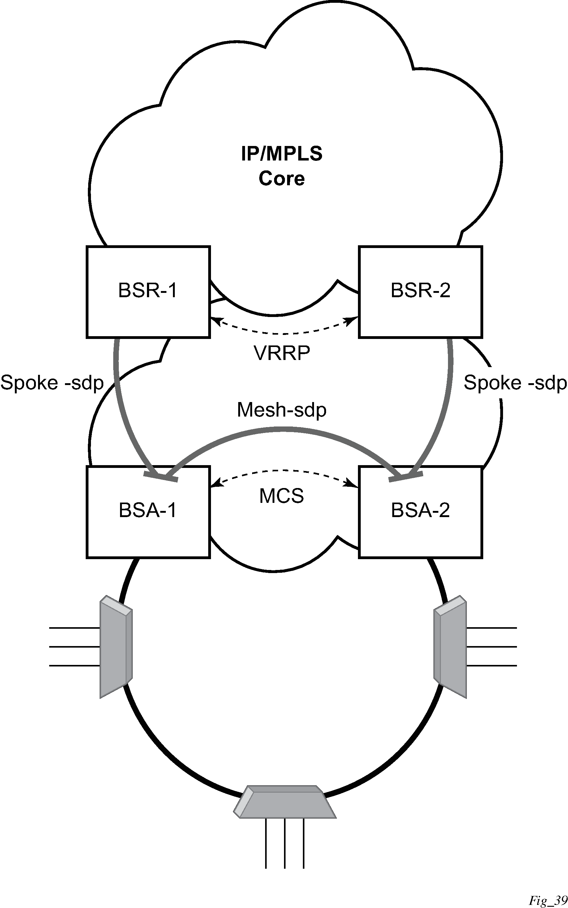
Typically, BTV service distribution is implemented in a separate VPLS service with a separate SAP per access-node. This extra VPLS is not explicitly indicated in Layer 2 CO dual homing - network diagram (and subsequent figures) but the descriptions refer to its presence.
From a configuration point of view in this model, it is assumed that all subscriber management features are enabled at the BSA level and that synchronization of the information (using multi-chassis synchronization) is configured between redundant pair nodes (BSA-1 and BSA-2 shown in Layer 2 CO dual homing - network diagram ). The multi-chassis synchronization connection is used only for synchronizing active subscriber host database and operates independently from dual-homing connectivity control. At the BSR level, there are no subscriber management features enabled.
The operation of redundancy at the BSR level through VRRP is the same as dual homing based on MC-LAG. The operation of dual homing at BSA level is based on two mechanisms. Ring control connection between two BSAs have two components, in-band and out-of-band communication. With in-band communication, BFD session between BSA-1 and BSA-2 running through the access ring and using dedicated IES/VPRN interface configured on both nodes. This connection uses a separate VLAN throughout the ring. The access nodes provides transparent bridging for this VLAN. The BFD session is used to continuously verify the integrity of the ring and to detect a failure somewhere in the ring.
With out-of-band communication, the communication channel is used by BSA nodes to exchange information about the reachability of individual access nodes as well as basic configurations to verify the consistency of the ring. The configuration information is synchronized through multi-chassis synchronization and therefore it is mandatory to enable multi-chassis synchronization between two nodes using the multi-chassis-ring concept.
In addition, the communication channel used by MC-LAG or MC-APS control protocol is used to exchange some event information. The use of this channel is transparent to the user.
Ring node connectivity check continuously checks the reachability of individual access nodes in the ring. The session carrying the connection is conducted on separate VLAN, typically common for all access nodes. SHCV causes no interoperability problems.
Steady-state operation of dual homed ring
Dual homing ring under steady-state condition illustrates the operation of the dual-homed ring. The steady state is achieved when both nodes are configured in a consistent way and the peering relation is up. The multi-chassis ring must be provisioned consistently between two nodes.
In-Band Ring Control Connection (IB-RCC) is in an operationally UP state. Note that this connection is set up using a bidirectional forwarding session between IP interfaces on BSA-1 and BSA-2.
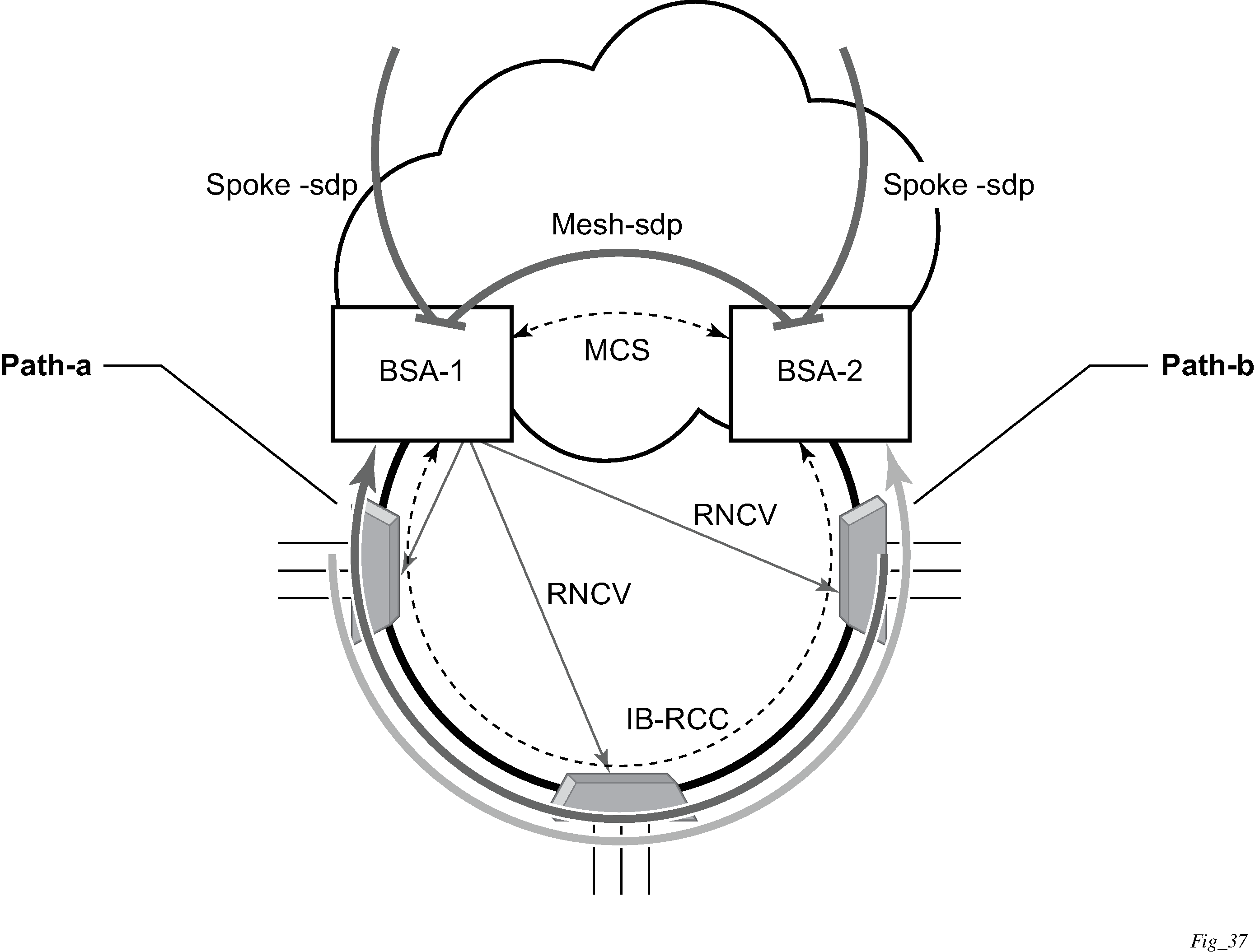
In Dual homing ring under steady-state condition, the ring is fully closed and every access node has two possible paths toward the VPLS core. Dual homing ring under steady-state condition refers to these as path-a and path-b. To avoid the loop created by the ring, only one of the paths can be used by any specific ring node for any specified VLAN. The assignment of the individual VLANs to path-a or path-b, respectively, has to be provisioned on both BSAs.
The selection of the primary BSA for both paths is based on the IP address of the interface used for IB-RCC communication (bidirectional forwarding session). The BSA with the lower IP address of the interface used as IB-RCC channel becomes the primary for ring nodes and their respective VLANs assigned to path-a. The primary for path-b is the other BSA.
In this example, each path in the ring has a primary and standby BSA. The functionality of both devices in steady state are as follows:
In the primary BSA:
All SAPs that belong to the path where the specific BSA is the primary node are operationally UP and all FDB entries of subscriber hosts associated with these SAPs point to their respective SAPs.
The primary BSA of a path performs periodical Ring Node Connectivity Verification (RNCV) check to all ring nodes.
In case of a RNCV failure, the respective alarm is raised. The loss of RNCV to the specified ring node does not trigger any switchover action even if the other BSA appears to have the connection to that ring node. If the BFD session is up, the ring is considered closed and the primary or standby behavior is driven solely by provisioning of the individual paths.
The ARP reply agent replies to ARP requests addressing subscriber hosts for which the BSA is primary.
In the standby BSA:
All SAPs that belong to a BSA’s path, the standby is operationally down and all FDB entries of subscriber hosts associated with those SAPs point toward the SDP connecting to the primary BSA (also called a shunt SDP).
In both primary and standby BSAs:
The information about individual path assignments is exchanged between both BSAs through multi-chassis synchronization communication channel and conflicting SAPs (being assigned to different paths on both BSA nodes) are forced to path-a (the default behavior).
For IGMP snooping, the corresponding multi-chassis IDs are targeting all subscriber-facing SAPs on both nodes. On the standby BSA node, the corresponding SAPs are in an operationally down state to prevent the MC traffic be injected on the ring twice.
Broken-ring operation and the transition to this state
Broken ring state illustrates the model with a broken ring (link failure or ring node failure). This state is reached in following conditions:
Both nodes are configured similarly.
Peering is up.
The multi-chassis ring is provisioned similarly between two nodes
IB-RCC is operationally down.
In this scenario, every ring node has only one access path toward the VPLS core and therefore, the Path-a and Path-b notion has no meaning in this situation.
Functionally, both BSAs are now the primary BSA for the reachable ring nodes and act as described in Steady-state operation of dual homed ring. For all hosts behind the unreachable ring nodes, the corresponding subscriber host FDB entries point to the shunt SDP.
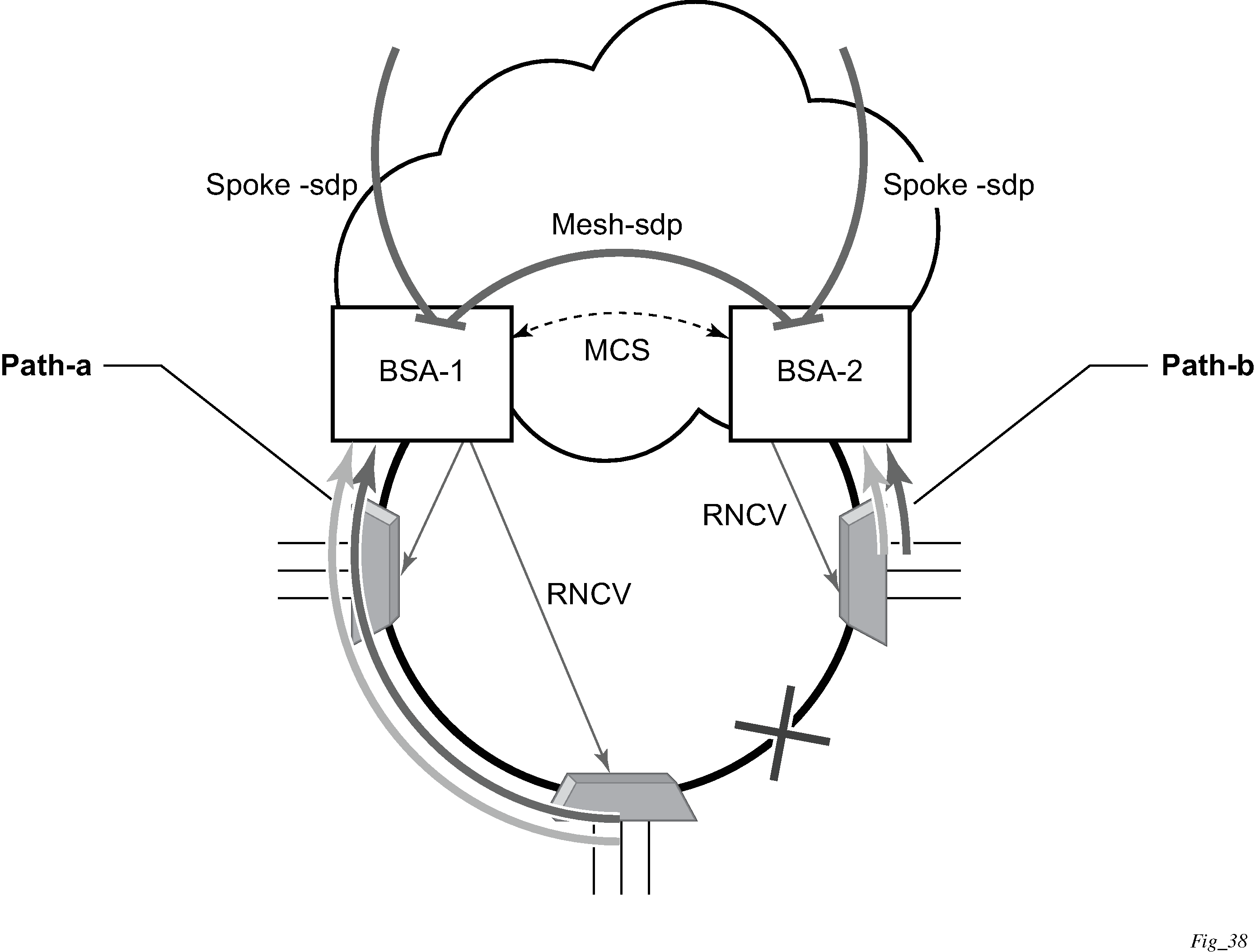
The mapping of individual subscriber hosts into the individual ring nodes is complicated, especially in the VLAN-per-service model where a single SAP can represent all nodes on the ring. In this case, a specified BSA can have subscriber hosts associated with the specified SAP that are behind reachable ring nodes as well as subscriber hosts behind un-reachable ring nodes. This means that the specified SAP cannot be placed in an operationally down state (as in a closed ring state), but rather, selectively re-direct unreachable subscriber states to the shunt SDP.
All SAPs remain in an operationally up state if the ring remains broken. This mainly applies for BTV SAPs that do not have any subscriber hosts associated with and do not belong to any particular ring node.
To make the mapping of the subscriber-hosts on the specified ring node automatically provisioned, the ring node identity is extracted during subscriber authentication process from RADIUS or from a Python script. The subscriber hosts which are mapped to non-existing ring node remain attached to the SAP.
At the time both BSA detect the break in IB-RCC communication (if BFD session goes down) following actions are taken:
Both nodes trigger a RNCV check toward all ring nodes. The node, which receives the reply first, assumes a primary role and informs the other BSA through an out-of-band channel. This way, the other node can immediately take actions related to the standby role without waiting for an RNCV timeout. Even if the other node receives an RNCV response from the specified ring node later, the primary role remains with the node that received the response first.
After assuming the primary role for hosts associated with the specified SAPs, the node sends out FDB population messages to ensure that new path toward the VPLS core is established. The FDB population messages are sourced from the MAC address of the default gateway used by all subscriber hosts (such as the VRRP MAC address) which is provisioned at the service level.
Transition from broken to closed ring state
By its definition, the multi-chassis ring operates in a revertive mode. This means that whenever the ring connectivity is restored, the BSA with lower IP address in the IB-RCC communication channel become primary for the path-a and the other way around for path-b.
After restoration of BFD session, the primary role, as described in Steady-state operation of dual homed ring, is assumed by respective BSAs. The FDB tables are updated according to the primary/standby role of the specified BSA and FDB population messages are sent accordingly.
Provisioning aspects and error cases
The multi-chassis ring can operate only if both nodes similarly configured. The peering relation must be configured and both nodes must be reachable at IP level. The multi-chassis ring with a corresponding sync-tag as a ring-name identifying a local port ID must be provision on both nodes. And the BFD session and corresponding interfaces must be configured consistently.
If the multi-chassis rings are not provisioned consistently, the ring does not become operational and the SAP managed by it is in an operationally up state on both nodes.
The assignment of individual SAPs to path-a and path-b is controlled by configuration of VLAN ranges according to the following rules:
By default, all SAPs (and therefore all VLANs on the specified port) are assigned to path-a.
An explicit statement defining the specified VLAN range assigns all SAPs falling into this range to the path-b.
An explicit statement defining the specified VLAN range defines all SAPs that are excluded from the multi-chassis ring control.
If a conflict in the configuration of VLAN ranges between two redundant nodes is detected, all SAPs falling into the ‟conflict-range” are assigned to path-a, on both nodes regardless the local configuration.
For QinQ-encapsulated ports the VLAN range refers to the outer VLAN.
Dual homing to two BSR nodes
Low depicts a single DSLAM dual-homed to two BSRs.
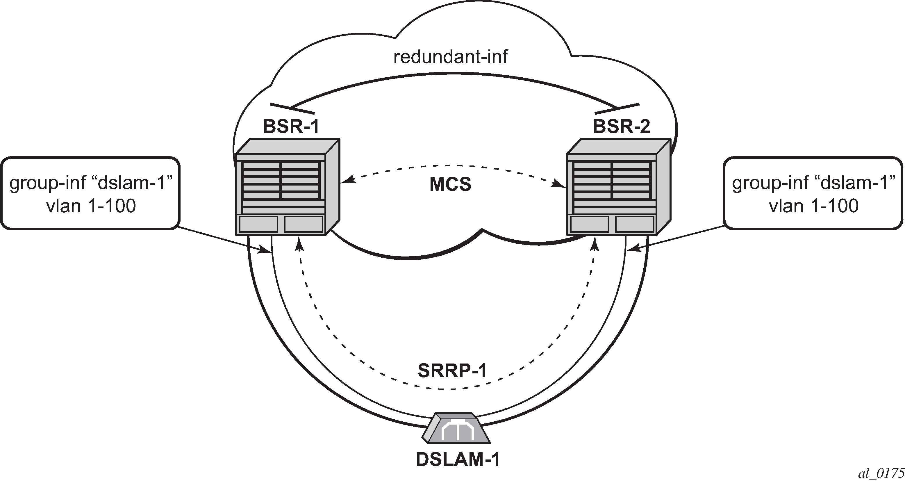
To provide dual-homing in the context of subscriber interfaces, the following items must be configured on both BSRs:
Group interface (dslam-1) with corresponding SAPs (vlan 1-100)
SRRP instance controlling a specific group interface
Redundant interface between BSRs to provide ‟shunt” connectivity
MCS connection to provide synchronization of dynamic subscriber-host entries
During the operation, BSR-1 and BSR-2 resolves active/standby relations and populates respective FDBs in such a way that, subscriber-host entries on the active node (SRRP master state) point to a corresponding group interface while subscriber-host entries on the standby node (SRRP backup state) point to the redundant interface. Note that the logical operation of the ring in the Layer 3 CO model is driven by SRRP. For more details on SRRP operation, see the Subscriber Routed Redundancy Protocol chapter.
MC services
The typical implementation of MC services at the network level is shown in MC services in a Layer 3-Ring topology (a).
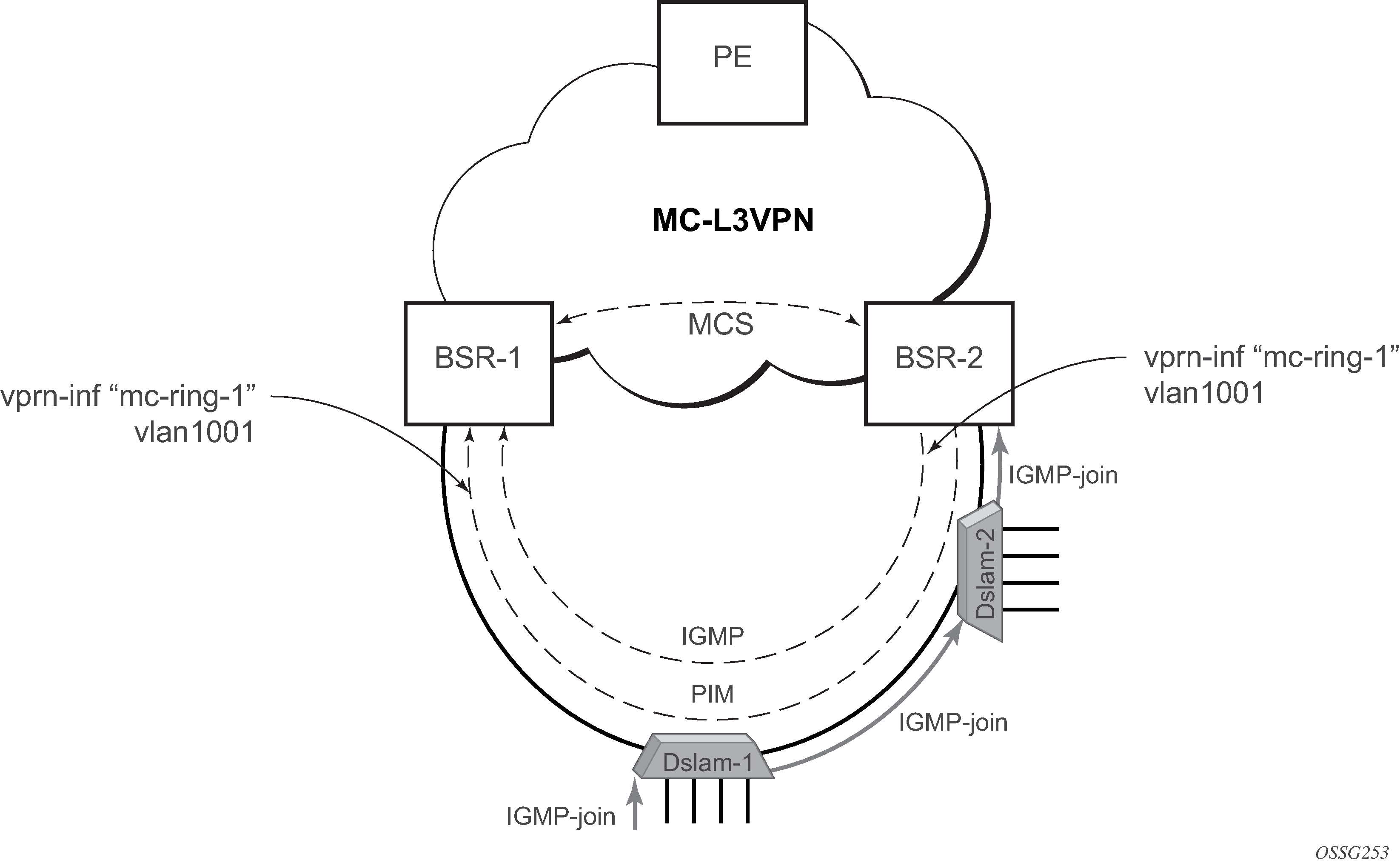
The IGMP is used to register joins and leaves of the user. IGMP messaging between BSRs is used to determine which router performs the querier role (BSR2 in MC services in a Layer 3-Ring topology (a)). PIM is used to determine which router is the designated router and the router that sends MC streams on the ring.
The access nodes have IGMP snooping enabled and from IGMP messaging between BSR, they are aware which router is the querier. In the most generic case, IGMP snooping agents (in access nodes) send the IGMP-joins messages only to IGMP-querier. The synchronization of the IGMP entries can then be performed through MCS. In some cases, access nodes can be configured in such a way that both ring ports are considered as m-router ports and IGMP joins are sent in both directions.
All of the above is a steady state operation which is transparent to the topology used in a Layer 2 domain.
A ring-broken state is shown in MC services on a Layer 3-ring topology (b).
In this case, IGMP and PIM messaging between BSRs is broken and both router assume role of querier and role of designated router. By the virtue of ring topology, both routers see only IGMP joins and leaves generated by host attached to a particular ‟half” of the ring. This means that both routers have ‟different” views on the dynamic IGMP state.

In principle, MCS could be used to synchronize both routers, but in case of a Layer 2 ring, the implementation sends all IGMP messages to the primary BSR which then performs IGMP processing and consequently, MCS sync. As a result, any race conditions are avoided.
Another ring-specific aspect is related to ring healing. The ring continuity check is driven by BFD which then drives SRRP and PIM messaging. BFD is optimized for fast detection of ring-down events while ring-up events are announced more slowly. There is a time window when routers are not aware that the ring is recovered. In the case of MC, this means traffic is duplicated on the ring.
To avoid this, the implementation of BFD provides a ‟raw mode” which provides visibility on ‟ring-up” events. The protocols, such as SRRP and PIM, use this raw mode instead of the BFD API.
Routed CO dual homing
Routed CO dual homing is a solution that allows seamless failover between nodes for all models of routed CO. In the dual homed environment, only one node forwards downstream traffic to a specific subscriber at a time. Dual homing involves several components:
Redundant Interface
This is used to shunt traffic to the active node for a specific subscriber for downstream traffic.
SRRP
This is used to monitor the state of connectivity to the DSLAM. See the SRRP section for more detail.
MCS
This is used to exchange subscriber host and SRRP information between the dual homed nodes.
Routed CO dual homing can be configured for both wholesaling models. Dual homing is configured by creating a redundant interface that is associated with the protected group interfaces. The failure detection mechanism can be SRRP. If SRRP is used, each node monitors the SRRP state to determine the priority of its own interface.
Dual homing is used to aggregate a large number of subscribers to support a redundancy mechanism that allows a seamless failover between nodes. Because of the Layer 3 nature of the model, forwarding is performed for the full subscriber subnet.
Redundant interfaces
In dual homing, a redundant interface must be created. A redundant interface is a Layer 3 spoke SDP-based interface that allows delivery of packets between the two nodes. The redundant interface is required to allow a node with a failed link to deliver packets destined for subscribers behind that link to the redundant node. Because subscriber subnets can span multiple ports it is not possible to stop advertising the subnet, therefore, without this interface the node would black hole.
The redundant interface is associated with one or more group interfaces. An interface in backup state uses the redundant interface to send traffic to the active interface (in the active node). The SAP structure under the group interface must be the same on both nodes as the synchronization of subscriber information is enabled on a group interface basis. Traffic can be forwarded through the redundant interface during normal operation even when there are no failed paths. See Dual homing example.
SRRP in dual homing
Subscriber Router Redundancy Protocol (SRRP) allows two separate connections to a DSLAM to operate in an active/standby fashion similar to how VRRP interfaces operate. Because the SRRP state is associated with the group interface, multiple group interfaces may be created for a specific port so some of the SAPs are active in one node and others active on the other node. While each SRRP pair is still allowed to be active/backup, the described configuration is allowed for load balancing between the nodes. In a failure scenario, subscriber bandwidth is affected. For more information about SRRP, see the Subscriber Routed Redundancy Protocol chapter.
If SRRP is configured before the redundant interface is up, and in backup state the router forwards packets to the access node using the backup interface but does not use the gateway MAC address. This applies to failures in the redundant interface as well. If the redundant interface exists and up the router sends downstream packets to the redundant interface and not use the backup group interface.
In a dual homing architecture the nodes must be configured with SRRP to support redundant paths to the access node. The nodes must also be configured to synchronize subscriber data and IGMP state. To facilitate data forwarding between the nodes in case some of the ports in a specific subscriber subnet are affected a redundant interface must be created and configured with a spoke. The redundant interface is associated with one or more group interfaces.
The service IDs for both the wholesale VPRN and the retailer VPRN must be the same in both nodes.
An interface in a backup state uses the redundant interface to send traffic to the active interface (in the active node). The SAP structure under the group interface must be the same on both nodes as the synchronization of subscriber information is enabled on a group interface basis.
SRRP is associated a group interface. Multiple group interfaces can be created for a specific port so that some of the SAPs are active in one node and others active on the other node. While every SRRP pair is still allowed to be active or backup the described configuration allows for load balancing between the nodes. In a failure scenario, subscriber bandwidth is affected.

Synchronization
To establish subscriber state the nodes must synchronize subscriber information. See the 7450 ESS, 7750 SR, 7950 XRS, and VSR Basic System Configuration Guide for multi-chassis synchronization configuration information. The operator must complete the configuration and the system must have data synchronized before the backup node may deliver downstream packets to the subscriber.
If dual homing is used with regular interfaces that run IGMP the nodes must be configured to synchronize the Layer 3 IGMP state.
The service IDs for both the wholesale VPRN and the retailer VPRN must be the same in both nodes.
Wholesale-retail multi-chassis redundancy
Multi-chassis redundancy for a retail service is enabled with the SRRP and redundant interface configuration on the wholesale group interface parented by the forwarding subscriber interface. The multi-chassis state (active or standby) of the retail subscriber host is determined from the SRRP state (master/non-master) of the group interface that parents the SAP of the retail subscriber host. The retail service ID must be equal on both nodes.
Sample wholesale service configuration:
 vprn 3000 customer 1 create
            description "Wholesale service"
            route-distinguisher 64500:3000
            auto-bind-tunnel
                resolution-filter
                    ldp
                    rsvp
                exit
                resolution filter
            exit
            vrf-target import target:64500:3000
            redundant-interface "red-int-1" create
                address 192.168.100.0/31
                ip-mtu 1500
                spoke-sdp 12:3000 create
                    no shutdown
            exit
            subscriber-interface "sub-int-1" create
                address 10.1.1.253/24 gw-ip-address 10.1.1.254
                address 10.1.2.253/24 gw-ip-address 10.1.2.254
                group-interface "group-int-1-1" create
                    dhcp
                        --- snip ---
                    exit
                    redundant-interface "red-int-1"
                    sap 1/1/6:1.4001 create
                        description "SRRP 1 message path"
                    exit
                    srrp 1 create
                        message-path 1/1/6:1.4001
                        send-fib-population-packets outer-tag-only
                        no shutdown
                    exit
                    pppoe
                        --- snip ---
                    exit
                exit
                group-interface "group-int-1-2" create
                    dhcp
                        --- snip ---
                    exit
                    redundant-interface "red-int-1"
                    sap 1/1/6:2.4001 create
                        description "SRRP 2 message path"
                    exit
                    srrp 2 create
                        message-path 1/1/6:2.4001
                        priority 50
                        send-fib-population-packets outer-tag-only
                        no shutdown
                    exit
                    pppoe
                        --- snip ---
                    exit
                exit
            exit
            no shutdown
        exit
Sample retail service configuration:
 vprn 3001 customer 1 create
            description "Retail service"
            route-distinguisher 64500:3001
            auto-bind-tunnel
                resolution-filter
                    ldp
                    rsvp
                exit
                resolution filter
            exit
            vrf-target target:64500:3001
            subscriber-interface "sub-int-rt-3000-1" fwd-service 3000 fwd-subscriber-
interface "sub-int-1" create
                address 10.1.11.253/24 gw-ip-address 10.1.11.254
                address 10.1.12.253/24 gw-ip-address 10.1.12.254
                dhcp
                    --- snip ---
                exit
                pppoe
                    --- snip ---
                exit
            exit
            no shutdown
        exit
Retail unnumbered host routes must be leaked in the wholesale service. Retail subscriber subnets and prefixes leaked in the wholesale service are needed to forward downstream shunted traffic over the redundant interface.
The address of an IPv4 unnumbered subscriber host (enabled with unnumbered {ip-int-name | ip-address} or allow-unmatching-subnets on the retail subscriber interface) is not contained in the subnets configured on the retail subscriber interface. The export of the IPv4 retail subscriber host routes to the wholesale service must be explicitly enabled with the export-host-routes command:
        vprn 3001 customer 1 create
            subscriber-interface "sub-int-rt-3000-1" fwd-service 3000 fwd-subscriber-
interface "sub-int-1" create
                allow-unmatching-subnets
                address 10.1.11.253/24 gw-ip-address 10.1.11.254
                address 10.1.12.253/24 gw-ip-address 10.1.12.254
                export-host-routes
                --- snip ---
The address of an IPv6 unnumbered subscriber host (enabled with ipv6 allow-unmatching-prefixes on the retail subscriber interface) is not contained in the IPv6 prefixes configured on the retail subscriber interface. IPv6 retail subscriber host routes are automatically exported to the wholesale service.
Downstream traffic arriving on a standby node (SRRP backup state) must be shunted over the redundant interface. Downstream traffic shunting can be reduced by advertising the retail subscriber subnets and prefixes from the active node (SRRP master state) with a more favorable metric using routing policies. To make retail subscriber subnets and prefixes SRRP state-aware, they have to be configured to track an SRRP instance that is active on a group interface of the connected wholesale subscriber interface:
        vprn 3001 customer 1 create
            subscriber-interface "sub-int-rt-3000-1" fwd-service 3000 fwd-subscriber-
interface "sub-int-1" create
                address 10.1.11.253/24 gw-ip-address 10.1.11.254 track-srrp 1
                address 10.1.12.253/24 gw-ip-address 10.1.12.254 track-srrp 2
                ---snip---
                ipv6
                    subscriber-prefixes
                        prefix 2001:db8:d001::/48 pd track-srrp 1
                        prefix 2001:db8:d002::/48 pd track-srrp 2
                        prefix 2001:db8:1:100::/56 wan-host track-srrp 1
                        prefix 2001:db8:1:200::/56 wan-host track-srrp 2
                    exit
                exit
Multi-chassis redundancy is supported for IPoE (IPv4 and IPv6) and PPPoE (IPv4 and IPv6) retail subscriber hosts and sessions.
Overlapping addresses on retail subscriber interfaces (enabled with config>service>vprn>subscriber-interface>private-retail-subnets) can be used in combination with multi-chassis redundancy.
When the private-retail-subnets command is enabled, downstream traffic arriving at retail services on a standby node (SRRP backup state) is shunted over to the redundant interface on a wholesale service. On a redundant interface, the service that each frame belongs to is identified by the source MAC address of the frame that includes service ID of a retailer service.
The service ID of each retailer service is synchronized over MCS. Therefore, service IDs for the retailer VPRN must be the same in both nodes.
Traffic shunting in the overlapping address scenario is supported for downstream traffic only.
SRRP and multi-chassis synchronization
To take full advantage of SRRP resiliency and diagnostic capabilities, the SRRP instance is tied to a MCS peering that terminates on the redundant node. After the peering is associated with the SRRP instance, MCS synchronizes the local information about the SRRP instance with the neighbor router. MCS automatically derives the MCS key for the SRRP instance based on the SRRP instance ID. An SRRP instance ID of 1 would appear in the MCS peering database with a MCS-key srrp-0000000001.
The SRRP instance information stored and sent to the neighbor router contains the following:
SRRP instance MCS key
service type and ID
subscriber IP interface name
subscriber subnet information
group IP interface information
SRRP group IP interface redundant IP interface name, IP address and mask
SRRP advertisement message SAP
local system IP address (SRRP advertisement message source IP address)
group IP interface MAC address
SRRP gateway MAC address
SRRP instance administration state (up or down)
SRRP instance operational state (disabled/becoming-backup/backup/becoming-master/ master)
current SRRP priority
remote redundant IP interface availability (available or unavailable)
local receive SRRP advertisement SAP availability (available or unavailable)
Dual homing and ANCP
The routers provide a feature related to exchange of control information between DSLAM and BRAS (BSA is described in this model). This exchange of information is implemented by in-band control connection between DSLAM and BSA, also referred to as ANCP connection.
In case of dual homing, two separate connections are set. As a consequence, there is no need to provide synchronization of ANCP state. Instead every node of the redundant-pair obtains this information from the DSLAM and creates corresponding an ANCP state independently.
SRRP enhancement
The SRRP enhancements addressed in this section is to reduce the need for redundant-interface between the pair of redundant nodes without sacrificing the subnet aggregation on the back-end.
Redundant BNG nodes are not always colocated. This means that the logical link associated with the redundant (shunt) interfaces is taking the uplink path therefore wasting valuable bandwidth (downstream traffic that arrives to the standby (SRRP backup state) node is routed by uplinks for the second time over to the active (SRRP master state) node).
To meet the requirement to reduce the existence of shunted traffic only to the short transitioning period between SRRP switchovers while the routing on the network side is converging, the following was required (referring to IP subnet per SRRP master group):
Share IP subnets over multiple SRRP instances. This is not mandatory, but it would help to load balance traffic over the two nodes. For example, IP subnets 10 and 11 can be shared over SRRP instances 10 and 20 on node 1, and the IP subnet 12 can be associated with the SRRP instance 30 on node 2.
SRRP aware routing
This allows to dynamically increase routing metric on the IP subnets advertised from the Master SRRP node in comparison to the Standby SRRP node. It also allows to advertise and withdraw routes from a routing protocol based on the SRRP state. In this way, downstream traffic is routed in a predictable manner toward the active node (SRRP master state).
SRRP Fate Sharing for SRRP instances 10 and 11. This ensures congruency of SRRP states on the same node. This is a necessary step toward SRRP-aware routing.
Figure 45. IP subnet per SRRP master group 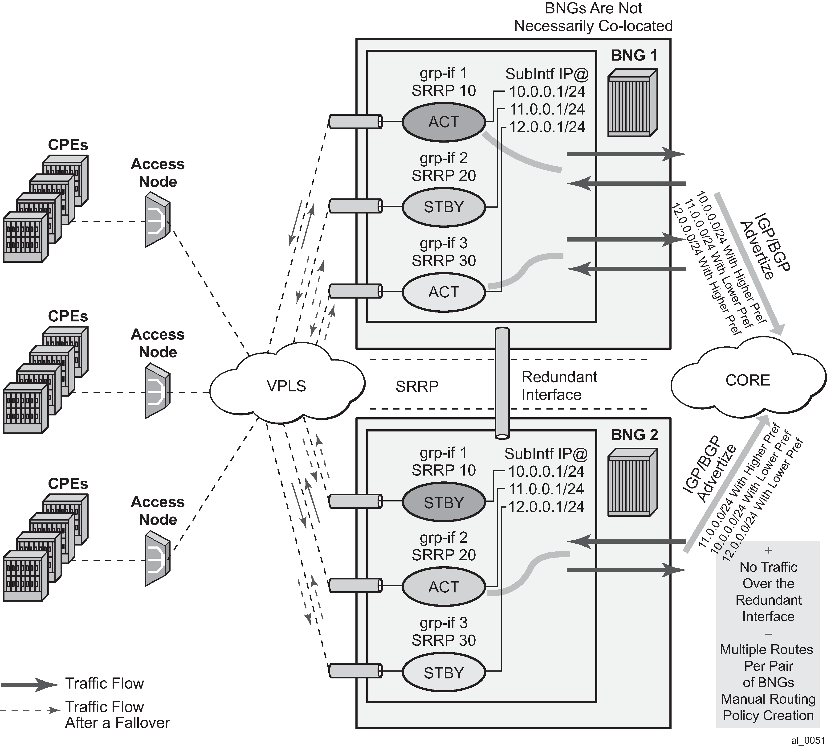
SRRP Fate Sharing
SRRP Fate Sharing is a concept in which a group of SRRP instances track a single operational-object composed of SRRP messaging SAPs. The SRRP instances behave as one (in the single failure case) with regards to SRRP state (init/master/backup). The group of SRRP instances that are sharing fate on a paired node are referred as a Fate Sharing Group (FSG).
Transition of a single messaging SAP within the FSG into a DOWN state forces the SRRP instance on top of it into the INIT state. Consequently, all other SRRP instances within the same FSG transitions into a Backup state. In other words, SRRP instances within the FSG all share the same fate as the failed SRRP instance as shown in FSG — single network failure. SRRP Fate Sharing provides optimal protection in the context of a single failure in the network.
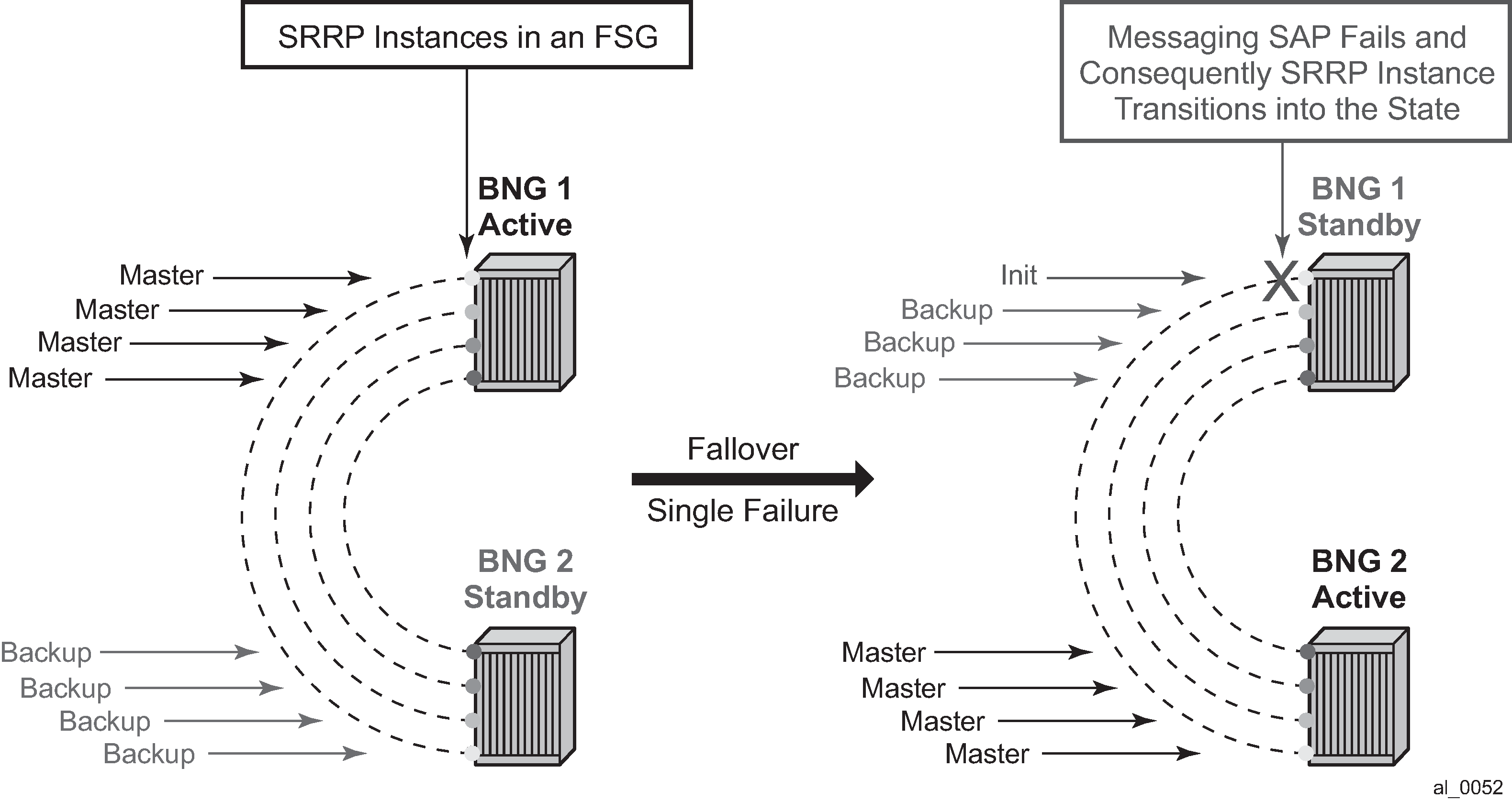
In the event of multiple network failures, the concept of the FSG breaks as there is a possibility that a ‛FSG’ contains SRRP instances that are in any of the three possible SRRP states: master, backup, or init. This Fate Sharing feature may not provide optimal protection when there are multiple network failures distributed over both redundant nodes.

The whereabouts of the failure in the network path that SRRP is designed to monitor are not always clearly reflected through SRRP states. For example, if the network failure is somewhere in the aggregation network beyond the direct reach of our BNG, SRRP instances on both BNG nodes can reach the SRRP master state. This is a faulty condition and the reason why solely monitoring of the SRRP states is not enough to protect against failures. On the other hand, the SRRP messaging SAP states are more indicative of the network failure because they can be tied into Eth-OAM.
After a single network failure is detected and as a result an SRRP instance transitions into a non-master state, the remaining SRRP instances in the FSG are forced into a backup state. This is achieved by changing the priority of each individual SRRP instance in the FSG.
When there are simultaneous multiple failures (multiple ports fail at the same time), it is possible that the SRRP instances within the FSG settle in any of the three possible SRRP states: Master, Backup, or Init. In such scenario, shunted traffic ensues.
In the premise of SRRP Fate Sharing, the network failure is reflected in the operational state of the messaging SAP over which SRRP runs. This is the case if the failure is localized to the BNG (somewhere on the directly connected link). In the case of non-localized failure (beyond the direct reach of the BNG node), Eth-OAM may be needed in to detect the remote end failure and consequently bring the SAP operationally into a DOWN state.
After the single network failure is detected, all instance within the FSG transitions into an SRRP non-Master state.
If there are no failures in the network, all SAPs are UP and SRRP instances within the FSG are in a homogeneous and deterministic state based on their configured priorities.
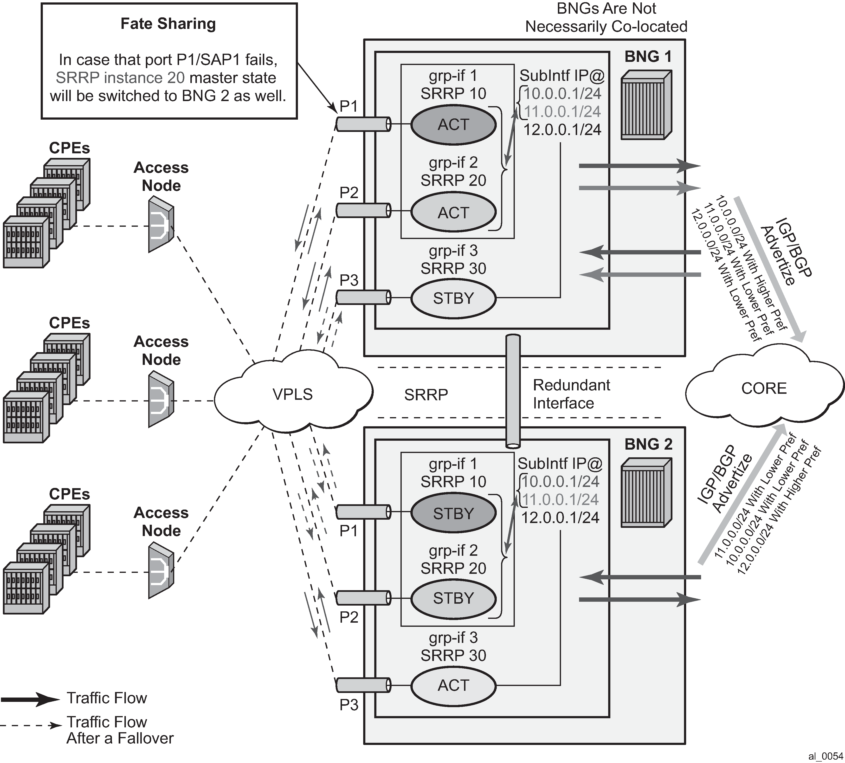
Failure Detection in a Fate Sharing Group
-
Dual homing over directly connected ports. No Eth-OAM is needed, AN is directly connected to the BNG.
Figure 49. Scenario 1 
-
Dual homing with aggregation network - aggregation network has no redundancy between Layer 2 switches (STP). To determine whereabouts of failure at point 1 in Scenario 2, Eth-OAM is needed.
Figure 50. Scenario 2 
-
Dual homing with aggregation network - aggregation network with redundancy between Layer 2 switches (STP). No Eth-OAM is needed in this case for successful operation. However, the failure detection is based on the failure of the directly attached ports.
Figure 51. Scenario 3 
-
Single homing with aggregation network. In this case, SRRP can protect only against direct failures. Any remote failure leaves a part of the network isolated from the subscriber point of view.
Figure 52. Scenario 4 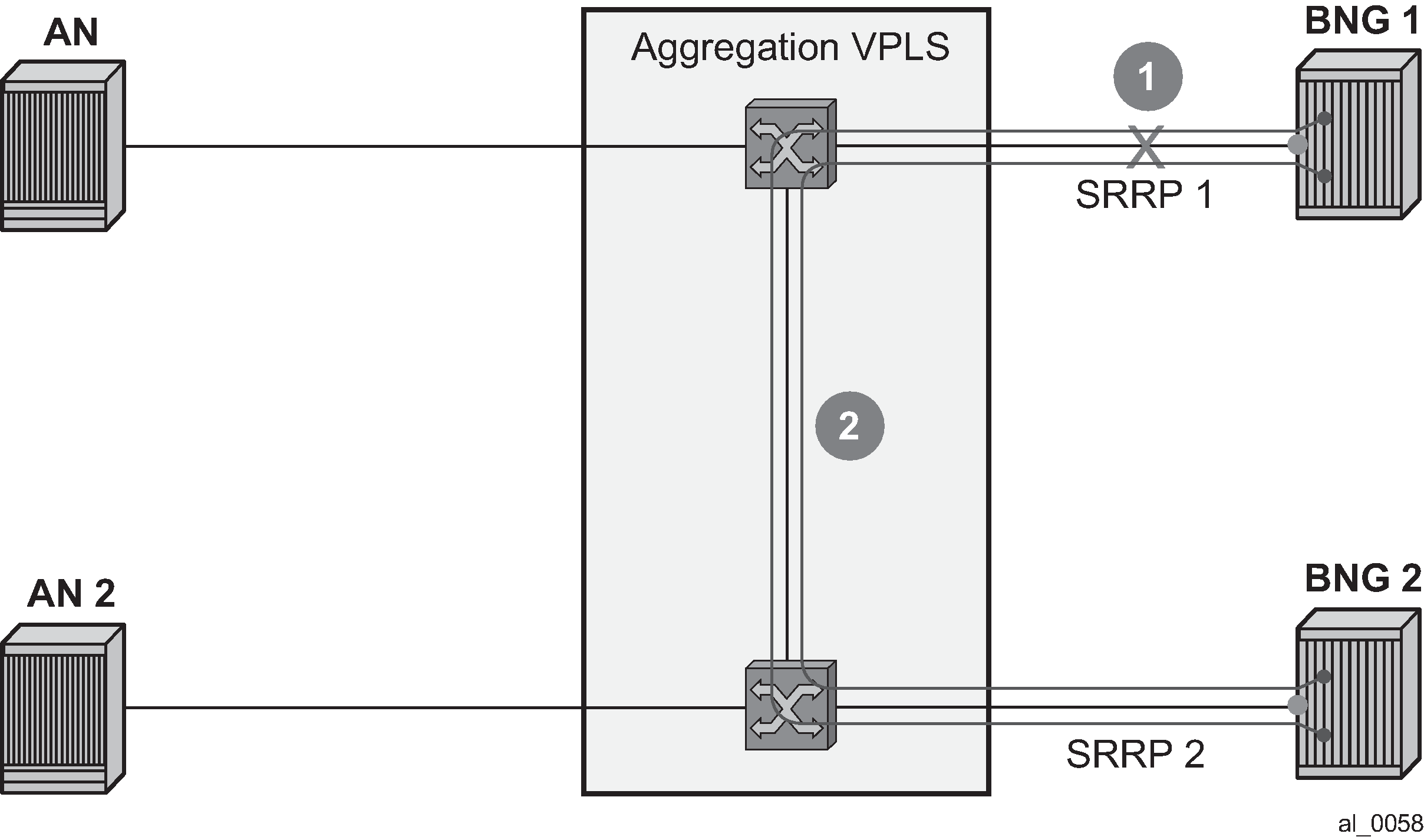
Fate sharing algorithm
Fate Sharing Group (FSG) is relaying on tracking the state of messaging SAPs over which SRRP instances run. An SRRP instance with the messaging SAP operationally DOWN transitions into the Init state.
The transitioning of any messaging SAP in a FSG into an UP/DOWN state triggers SRRP priority adjustment within the FSG. The SRRP priorities should be chosen carefully to achieve the wanted behavior. They are modified dynamically as the SAP states change. The range in which SRRP priorities can be modified is from 1 to the SRRP priority that is initially configured under the SRRP node. Here are some general guidelines for choosing SRRP priorities in a FSG:
Initially configured SRRP priorities for all SRRP instance within the FSG within the node should be the same.
Initially configured SRRP priorities should be different between pairing FSGs. For example, SRRP instances in the BNG node A within an FSG all have the same SRRP priority ‛X’, while corresponding SRRP instances on the paired node within corresponding FSG all have SRRP priority ‛Y’. This ensures that the SRRP master state is clearly defined between the two BNG nodes. This step is not mandatory as SRRP naturally breaks the master state election tie in the case that all SRRP priorities are the same. However, following this step may provide a clearer view from an operational perspective.
The priority-step parameter used for dynamic SRRP priority adjustment must be greater than the difference in initially configured SRRP priorities between two BNG nodes. This ensures that a single failure event triggers the SRRP switchover. Otherwise, if the dynamically lowered SRRP priority is still greater than the one from the SRRP peer, the switchover would not be triggered. Therefore, the fate sharing concept would not function as intended.
Initially configured SRRP priority of each SRRP instance should be greater than the (anticipated) number of SRRP instances in a FSG multiplied by the SRRP priority-step. This ensures that the dynamically priority never tries to go below 1. There is a code check that prevents SRRP priority going below 1. Nonetheless, it is recommended not to get into a situation where this needs to be enforced in the code.
The priorities can never be less than 1 or greater than initially configured SRRP priority.
Example scenarios:
Assume 3 SRRP instances in a FSG. The SRRP instances in the FSG-1 on BNG 1 have the priority of 100, while the SRRP instances in the FSG-2 on BNG 2 have the priority of 95. The priority-step is 6. The SRRP instances and underlying messaging SAPs are referred to as SRRP 1, 2, 3 and SAP 1,2,3, respectively.
Initialization:
Scenario 1 – all SAPs are operationally UP.
BNG 1 boots up and all messaging SAPs transition into the UP state. When the first SRRP instance in FSG-1 comes up, it looks under the FSG to finds out how many messaging SAPs are operationally UP. Because all messaging SAPs are operationally UP, this first SRRP instance assumes its initially configured priority of 100. The other two SRRP instances in the same FSG follows the same sequence of events.
BNG 2 follows the same flow of events. As a result, all SRRP instances within the corresponding FSG are in the SRRP master state on BNG 1.
Scenario 2 – messaging SAP 1 is operationally DOWN on BNG 1, the rest of the messaging SAPs are operationally UP.
SRRP 2 and 3, during the initialization, pick up SRRP priority of 94 (100 – 1*priority-step).
On BNG 2, all messaging SAPs are UP and consequently all SRRP instances within the FSG on BNG 2 have SRRP priority of 95. The SRRP instances are in the SRRP master state on BNG 2.
Scenario 3 – Continuing from scenario 2, the SAP 1 on BNG 1 transitions into the UP state. SRRP priority of each SRRP instance in FSG-1 is increased by 6, bringing it to 100, enough to assume Mastership.
Adding a New Instance into an FSG
To introduce minimal network disruption, first create messaging SAPs in both BNG nodes and ensure that both SAPs are operationally UP. Then a new SRRP 4 instance should be created on both BNG nodes. The next step would be to include this new messaging SAP into a SAP monitoring group. And finally, the SRRP-4 is added into the FSG (1 and 2). This triggers the recalculation of SRRP priorities for the existing FSG-1 and FSG-2. Because all SRRP priorities are at the maximum (initially configured priority), nothing changes.
There are more disruptive ways of adding an SRRP instance into a FSG. One such example would be in the case where SRRP priorities are not at their maximum (initially configured) priority. If an SRRP instance is first added into an FSG that is in a backup state, this would increase the FSG priority and potentially cause a switchover. If the SRRP instances is then added in a FSG on the peer BNG (previously SRRP master state), the priority of this FSG would be increased again and the switchover would unnecessarily occur for the second time. The new SRRP instances, when operational, should always be added in the FSG with SRRP master state first.
SRRP priority re-calculation within the FSG is triggered by the following events:
SRRP initialization
addition of a SAP under the monitoring group
messaging SAP failure
This priority calculation looks into how many SAPs are in the DOWN state within the monitored SAP group. Based on this number, the priority is calculated as follows:
SRRP priority = configured-priority – priority-step * num_down_SAPs.
SRRP aware routing - IPv4/IPv6 route advertisement based on SRRP state
There are three cases with its own specifics:
-
subscriber interface routes (IPv4/IPv6)
managed routes
subscriber management Routes (/32 IPv4 hosts routes and IPv6 PD wan-host routes)
Depending on the route type, the action is to either modify the route metric based on the SRRP state that the route is tracking, or to advertise/withdraw the route based on the SRRP state that the route is tracking. The action is defined in the routing policy and it is based on the new attributes with which the routes are associated.
To achieve a better granularity of the routes that are advertised, an origin attribute is added to the subscriber management routes (/32 IPv4 routes and IPv6 PD wan-host) with three possible values:
aaa
IPv4
subscriber-management /32 host routes that are originated through RADIUS framed-ip-address VSA other than 255.255.255.254. The 255.255.255.254 returned by the RADIUS indicates that the BNG (NAS) should assign an IP address from its own pool.
IPv6
subscriber-management routes that are originated through framed-ipv6-prefix (SLAAC), delegated-ipv6-prefix (IA_PD) or alc-ipv6-address (IA_NA) RADIUS attributes. This is valid for IPoE and PPPoE type host.
dynamic
IPv4
subscriber-management /32 host routes that are originated through the DHCP server (local or remote) and also RADIUS framed-ip-address=255.255.255.254 (RFC 2865).
IPv6
subscriber-management routes that are assigned through the local DHCPv6 server pools whose name is obtained through Alc-Delegated-IPv6-Pool (PD pool) and Framed-IPv6-Pool (NA pool) RADIUS attributes. This is valid for IPoE and PPPoE type hosts.
In addition, for IPoEv6 only, the pool name can be also obtained through the ipv6-delegated-prefix-pool (PD pool) and ipv6-wan-address-pool (NA pool) from LUDB.
static
IPv4
subscriber-management /32 host routes that are originated through LUDB. This also covers RADIUS fallback category (RADIUS falls back to system-defaults or to LUDB).
IPv6
subscriber-management routes obtained from LUDB through the ipv6-address (IA_NA) or ipv6-prefix (IA_PD). This is supported only for IPoE.
Overall, the following new route attribute is added:
state: srrp-master, srrp-non-master
The existing origin attribute is expanded to contain the following values:
origin: aaa, dynamic, static
These two attribute types are applied:
The state attribute is applied to all three route types: subscriber interface routes, managed routes and subscriber management routes. Each route listens to the SRRP state.
If an attribute is defined in the routing policy as a match condition (from statement) but the route itself does not have this attribute, the route is evaluated into a non-match condition.
The origin attribute is always applied only to subscriber management routes. No additional statement is needed to explicitly apply this attribute as it may be the case for the state attribute.
Every time there is a change in the attribute associated with the route, the route is re-evaluated in the RTM by the routing policy and corresponding action is taken.
Subscriber interface routes (IPv4 and IPv6)
Optimized routing and elimination of downstream shunt traffic during normal operation can be achieved by statically favoring the routes on the network side that are advertised with an increased metric by active nodes (SRRP master state).
The downside of this static approach is that during the port or card failure and consequently a SRRP switchover, the node with the failed port or card continues to advertise routes with the same high metric if the subscriber interface is in the ‛UP’ state (or a single SAP under it). That is, the network side is not aware of the switchover. It continues to forward traffic to the standby node, and as a result, heavy shunt traffic ensues. To effectively deal with this, the network side must be aware of the routing change that occurred in the access layer.
When failure is detected, the metric for the route is changed automatically based on the following configuration:
configure
    service <type> <id>
        subscriber-interface <ip-int-name>
            address <ip-address> gw-ip-address <gw-address> track-srrp <srrp-inst> holdup-time <msec>
            ipv6
            subscriber-prefixes
                prefix <ipv6-prefix> pd track-srrp <srrp-id> holdup-time <msec>
                prefix <ipv6-prefix> wan-host track-srrp <srrp-id> holdup-time <msec>


    policy-options
        begin
           policy-statement <name>
            entry 1
                from
                    protocol direct
                    state ‛srrp-master’
                    exit
               action accept
                metric set 100
                exit
            exit
            entry 2
                from
                    protocol direct
                    state ‛srrp-non-master’
                    exit
                action accept
                metric subtract 10
                exit
            exit
            entry 3
                from
                    protocol direct
                    exit
                action accept
                exit
            exit
This configuration ensures that the route metric is changed for the subscriber interface routes based on the SRRP state while the other, non-subscriber directly attached routes are unaffected by SRRP.
The route advertisement based on SRRP State requirement is applicable to BGP and IGP.
The routing policy also provides the flexibility to prevent route advertisement (action reject) instead of changing the route metric.
Although this feature is designed to minimize or eliminate the use of the redundant interface, it is important to note that the redundant interfaces are still used in the case of transient conditions. An example of such condition would be:
Messaging SAP Fails
SRRP switches over
Stale routing in the core is still in the effect while the metric is being propagated (or the route is being advertised or withdrawn). During this time, traffic is flowing over the redundant interface.
Network convergence is complete
Traffic in the network core is redirected to the new active node (SRRP master state)
Managed routes
Only the state attribute is applicable to managed routes, and only to the ones that are synchronized (static and RADIUS obtained – framed-route and framed-ipv6-route). The managed routes obtained by BGP are not synchronized and this feature is not applicable to them.
Based on the SRRP state, the managed route can be either advertised with a modified metric or be withdrawn altogether.
For example:
Managed routes that are tracking SRRP state are only advertised from the active node (SRRP master state) and denied from standby node (SRRP backup state). All other managed routes that are not tracking SRRP state are advertised regardless of the SRRP state.
policy-options
    begin
        policy-statement <name>
            entry 1
                from
                    protocol managed
                    state ‛srrp-master’
                    exit
                action accept
                exit
            exit
            entry 2
                from
                    protocol managed
                    state ‛srrp-non-master’
                    exit
                action reject
                exit
            exit
            entry 3
                from
                    protocol managed
                    exit
                action accept
                exit
            exit
Subscriber management routes (/32 IPv4 host routes, IPv6 PD WAN host routes)
Both attributes (state and origin) are applicable to the subscriber management routes.
For example:
A service provider wants to advertise only subscriber management routes with the origin dynamic and AAA from the active node (SRRP master state). Routes with the LUDB origin are not advertised. The standby node is not advertising any /32 subscriber management routes.
policy-options
    begin
        policy-statement <name>
            entry 1
                from
                    origin dynamic
                    state ‛srrp-master’
                    exit
            action accept
            exit
        exit
    exit
           entry 2
                from
                    origin dynamic
                    state ‛srrp-master’
                    exit
            action accept
            exit
        exit
Default action is reject.
Activating SRRP state tracking
The SRRP state tracking by routes is turned on only when needed.
For subscriber-interface routes (IPv4 and IPv6), this is performed explicitly.
subscriber-interface <ip-int-name>
    address <ip-address> gw-ip-address <gw-address> track-srrp <inst-name> holdup-
time <msec>
        ipv6
        subscriber-prefixes
            prefix <ipv6-prefix> pd track-srrp <srrp-id> holdup-time <msec>
            prefix <ipv6-prefix> wan-host track-srrp <srrp-id> holdup-time <msec>
For managed and subscriber management routes, this is explicitly enabled under the group interface:
group-interface <ip-int-name>
    srrp-enabled-routing holdup-time <msec>
SRRP in conjunction with a PW in ESM environment – use case
In specific cases, subscriber traffic is terminated on the BNG by an Epipe. In this case, the subscriber traffic can be offloaded onto a plain Ethernet port by a VSM module (a ‛loop’) so that it can be terminated in ESM. Epipes can be configured in A/S configuration and terminated on two BNG nodes in multihomed environment.
In these multi-homed environment with Epipes and ‛loops’, the ESM itself detaches from the Epipe, which brings the subscriber traffic to the BNG. Because of that, the ESM would not know if the PW’s state is active or standby. As a result, in the downstream direction, traffic could end up being forwarded toward the standby PW, effectively being black-holed.
To overcome this, SRRP can be used in conjunction with an additional mechanism to help monitor the activity of the PWs. This monitoring mechanism is very similar to Fate-sharing. The difference in this case is that the messaging SAP (instead of SRRP instance) is monitoring the activity of the PW. As a result, the SRRP messaging SAP reflects the state of the PW. For example, the PW in a Standby mode would cause the messaging SAP to be in the DOWN state while the PW Active state would cause the messaging SAP to be in the UP state. That is, the SRRP instance reflects the operational state of the messaging SAP. SRRP is indirectly tied into PW state.
Modifying the priority of SRRP instance based on PW’s state as a mean of tying the SRRP master state to the active PW would not help here as SRRP messages are not flowing over standby PWs. This is why SRRP state must be enforced by the messaging SAP.
Fate-sharing for PW termination in conjunction with SRRP is not supported.
Metric adjustment for the subscriber routes is supported. After the tracked SRRP instance transitions into a non-master SRRP state, the state attribute of the route changes and the appropriate action defined in the routing policy is taken.
Group monitor
The failure detection mechanism to trigger an action within FSG relies on the operational state of the messaging SAP. Such failure detection mechanism is referred as a group monitor.
Group monitor can also be used to detect the state change of the PW. PW state change is reflected in the messaging SAP which in turn triggers the state change of an SRRP instance.
All this is implemented through an oper-group object which is described in the 7450 ESS, 7750 SR, 7950 XRS, and VSR Layer 3 Services Guide: IES and VPRN. All entities that needs to be monitored (messaging SAPs and PWs) are associated with this oper-group object. Finally, an SRRP instance (in case of FSG) or a messaging SAP (in case of PW) is instructed to monitor the entities in the oper-group object. State transitions of objects in a oper-group object trigger state transitions of entities that are monitoring them (messaging SAPs and SRRP instances). State transitions of monitored objects in a oper-group cause the following actions:
With FSG, priorities of SRRP instances are recalculated.
With PW termination on BNG, the operational state of the messaging SAP is changed.
The following is an overview of the CLI syntax showing the principles to create an operational group (oper-group). For command descriptions and full syntax, see the 7450 ESS, 7750 SR, 7950 XRS, and VSR Classic CLI Command Reference Guide and 7450 ESS, 7750 SR, 7950 XRS, and VSR MD-CLI Command Reference Guide.
Create an oper-group.
     config>service
         oper-group <name> [create]
Add a SAP to the oper-group.
     config>service(ies | vprn)>sub-if>grp-if>sap
         oper-group <name>
Link the state of an oper-group to the SAP. A messaging SAP can monitor the state of a PW.
     config>service(ies | vprn)>sub-if>grp-if>sap
         monitor-oper-group <name>
Link the state of an oper-group to the SRRP instance. A state transition of an object in the oper-group (not the state of the oper-group itself) triggers an SRRP priority recalculation. When an object within the oper-group goes down, the SRRP priority is lowered by a priority step. The SRRP priority is adjusted on every state transition of an oper-group member object.
     config>service(ies | vprn)>sub-if>grp-if>srrp <srrp-id>
         monitor-oper-group <name> priority-step [0-253]
Add a PW to the oper-group. A messaging SAP monitors the oper-group and assumes the state according to the state of the PW in the oper-group. A standby or a down PW state causes the messaging SAP to assume a down state. Otherwise, the messaging SAP would be in the UP state. In order for the SAP to assume the down state, both RX and TX sides of the PW must be shut down. In other words, a PW in standby mode also must have the local TX disabled by the via the ‛slave’ flag (standby-signaling-slave command in the spoke SDP context). Without the TX disabled, the SAP monitoring the PW does not transition in the down state.
     config>service>epipe>spoke-sdp
         oper-group <name>
A hold timer is provided within the oper-group command to suppress flapping of the monitored object (SAP or pseudowire).
Pseudowire example shows an example with ESM over pseudowire through a VSM loop.

*A:Dut-C>config>service>epipe# info
----------------------------------------------
            endpoint "x" create
                standby-signaling-master
            exit
            sap 1/1/7:1 create
            exit
            spoke-sdp 1:1 endpoint "x" create
                precedence primary
                no shutdown
            exit
            spoke-sdp 2:1 endpoint "x" create
                no shutdown
            exit
            no shutdown
----------------------------------------------

*A:Dut-A>config>service>epipe# info
----------------------------------------------
            sap ccag-1.b:11 create
            exit
            spoke-sdp 2:1 create
                standby-signaling-slave
                oper-group "1"
                no shutdown
            exit
            no shutdown
----------------------------------------------
*A:Dut-B>config>service>epipe# info
----------------------------------------------
            sap ccag-1.b:11 create
            exit
            spoke-sdp 2:1 create
                standby-signaling-slave
                oper-group "1"
                no shutdown
            exit
            no shutdown
----------------------------------------------
*A:Dut-A>config>service>ies# info
----------------------------------------------
            redundant-interface "redif11" create
                address 10.1.1.2/24 remote-ip 10.1.1.4
                spoke-sdp 1:1 create
                    no shutdown
                exit
            exit
            subscriber-interface "subif_1" create
                shutdown
                address 10.1.1.2/24 gw-ip-address 10.1.1.100
                group-interface "grpif_1_2" create
                    shutdown
                    redundant-interface "redif11"
                exit
            exit
            subscriber-interface "subTest" create
                address 10.1.1.2/24 gw-ip-address 10.1.1.254
                group-interface "grpTest" create
                    redundant-interface "redif11"
                    sap ccag-1.a:1 create
                    exit
                    sap ccag-1.a:11 create
                        monitor-oper-group "1"
                    exit
                    srrp 11 create
                        message-path ccag-1.a:11
                        no shutdown
                    exit
                exit
            exit
            no shutdown
----------------------------------------------
*A:Dut-B>config>service>ies# info
----------------------------------------------
            redundant-interface "redif11" create
                address 10.1.1.4/24 remote-ip 10.1.1.2
                spoke-sdp 1:1 create
                    no shutdown
                exit
            exit
            subscriber-interface "subif_1" create
                shutdown
                address 10.1.1.4/24 gw-ip-address 10.1.1.100
            exit
            subscriber-interface "subTest" create
                address 10.1.1.4/24 gw-ip-address 10.1.1.254
                group-interface "grpTest" create
                    redundant-interface "redif11"
                    sap ccag-1.a:1 create
                    exit
                    sap ccag-1.a:11 create
                        monitor-oper-group "1"
                    exit
                    srrp 11 create
                        message-path ccag-1.a:11
                        no shutdown
                    exit
                exit
            exit
            no shutdown
----------------------------------------------
*A:Dut-B>config>service>ies# show srrp
===============================================================================
SRRP Table
===============================================================================
ID        Service        Group Interface                 Admin     Oper
-------------------------------------------------------------------------------
11        1              grpTest                         Up        initialize
-------------------------------------------------------------------------------
No. of SRRP Entries: 1
===============================================================================
*A:Dut-A>config>service>ies# show srrp
*A:Dut-A>config>service>ies#
===============================================================================
SRRP Table
===============================================================================
ID        Service        Group Interface                 Admin     Oper
-------------------------------------------------------------------------------
11        1              grpTest                         Up        master
-------------------------------------------------------------------------------
No. of SRRP Entries: 1
===============================================================================
Subscriber QoS overrides
Subscriber QoS overrides enable per-subscriber and per-SLA Profile Instance QoS parameter customization to reduce the amount of sub-profiles and sla-profiles that must be configured on the router to cover all needed service level combinations.
Subscriber QoS overrides can be installed at subscriber host or session creation:
with an Alc-Subscriber-QoS-Override VSA in a RADIUS Access-Accept message
with a Charging-Rule-Install/Charging-Rule-Definition/QoS-Information AVP in a DIAMETER Gx CCA message
Note:To use the APN-Aggregate-Max-Bitrate-DL and APN-Aggregate-Max-Bitrate-UL AVPs for QoS overrides, a corresponding 3gpp-qos-mapping must be configured in the DIAMETER Gx application policy:
>config>subscr-mgmt>diam-appl-plcy>gx>3gpp-qos-mapping>
[no] apn-ambr-dl - Configure the APN-AMBR mapping for the downlink
[no] apn-ambr-ul - Configure the APN-AMBR mapping for the uplink
Subscriber QoS overrides can be installed, updated or removed in a mid-session change with a RADIUS CoA, a DIAMETER Gx RAR or a DIAMETER Gx CCA message using the same attributes as for a subscriber host or session creation.
Subscriber QoS overrides can also be activated using subscriber services. See QoS override-based subscriber service for details.
The format of the [26.6527.126] Alc-Subscriber-QoS-Override VSA is described in the 7450 ESS, 7750 SR, and VSR RADIUS Attributes Reference Guide.
The format of QoS Overrides AVP's in the 3GPP-1016 QoS-Information AVP are described in the 7750 SR and VSR Gx AVPs Reference Guide.
The following SLA profile instance QoS parameters can be overridden:
ingress and egress queue: pir, cir, mbs, cbs
ingress and egress policer: pir, cir, mbs, cbs
egress queue class weight (applies to HSQ card only)
egress queue wrr weight (applies to HSQ card only)
egress aggregate rate (applies to HSQ card only)
egress wrr group: rate, class weight (applies to HSQ card only)
The following subscriber QoS parameters can be overridden:
egress aggregate rate
ingress and egress root arbiter rate
ingress and egress intermediate arbiter rate
ingress and egress user scheduler: rate, cir
The ingress and egress user scheduler overrides through DIAMETER Gx can only be performed using APN-Aggregate-Max-Bitrate-UL and APN-Aggregate-Max-Bitrate-DL AVPs and requires the following 3gpp-qos-mapping in the DIAMETER Gx Application policy
         >config>subscr-mgmt>diam-appl-plcy>gx>
                 3gpp-qos-mapping
                      apn-ambr-dl scheduler <scheduler-name>
                      apn-ambr-ul scheduler <scheduler-name>
                  exit
The operational value of some of the QoS parameters can be derived from different sources.
For queue and policer QoS parameters, the following hierarchy applies (highest priority is listed first):
Credit Control overrides
Subscriber Services QoS overrides
Subscriber QoS overrides (RADIUS, DIAMETER)
Overrides configured at sla-profile level
Queue parameters set in QoS policy level
For scheduler and arbiter overrides, the following hierarchy applies:
ANCP overrides
Subscriber Services QoS overrides
Subscriber QoS overrides (RADIUS, DIAMETER)
Overrides configured at sub-profile level
Scheduler/arbiter parameters as configured in scheduling/policer-control-policy
Up to 18 QoS overrides can be installed per subscriber host or session. A new set of QoS overrides received using a mid-session change replaces the previous set of QoS overrides.
QoS overrides are always stored as part of the subscriber host or session data but are only applied when the override is valid in the active QoS configuration. For example:
An egress queue 5 PIR rate override is stored with the subscriber session but not applied when the sap-egress QoS policy has no queue 5 defined
RADIUS or DIAMETER Gx initiated QoS overrides can be displayed with the following show commands:
show service id service-id | name ipoe session detail
show service id service-id | name ppp session detail
show service id service-id | name dhcp lease-state detail
show service id service-id | name dhcp6 lease-state detail
show service id service-id | name arp-host detail
show service id service-id | name slaac-host detail
Subscriber services initiated QoS overrides can be displayed with:
show service sub-services
The active QoS overrides per-subscriber and per-SLA Profile Instance can be displayed with:
show service active-subscribers detail
The number of allocated and free Subscriber SLA Profile Instance QoS overrides, QoS Intermediate Arbiter Overrides and QoS User Scheduler Overrides per-line card can be monitored with the tools dump resource-usage card CLI command.
Subscriber QoS overrides are synchronized through MCS in a dual-homing environment. QoS overrides are not stored in the subscriber-mgmt application persistence file.
Dual-Stack Lite
The DS-Lite feature is supported on the 7710 SR-Series in combination with the MS-ISA to function as a DS-Lite Address Family Transition Router (AFTR).
DS-Lite is an IPv6 transition technique that allows tunneling of IPv4 traffic across an IPv6-only network. Dual-stack IPv6 transition strategies allow service providers to offer IPv4 and IPv6 services and save on OPEX by allowing the use of a single IPv6 access network instead of running concurrent IPv6 and IPv4 access networks. DS-Lite has two components: the client in the customer network, known as the Basic Bridging BroadBand element (B4) and an Address Family Transition Router (AFTR) deployed in the service provider network.
DS-Lite leverages a network address and port translation (NAPT) function in the service-provider AFTR element to translate traffic tunneled from the private addresses in the home network into public addresses maintained by the service provider. On the 7750 SR, this is facilitated through the Carrier Grade NAT function.
As shown in Dual-Stack Lite, DS-Lite has two components, a softwire initiator in the RG and a softwire concentrator, deployed in the service provider network, where control-less IP-in-IP (using protocol 4 - IPv4 in IPv6) is used for tunneling. When using control-less protocol, packets are sent on the wire for the remote softwire endpoint without prior setup of a tunnel.
The softwire initiator in the home network is combined with a routing function, where the default route is passed to the softwire pseudo-interface. Note that there is no NAT function, therefor, the private IP addresses of the home network are encapsulated without source address modification, and forwarded to the softwire concentrator where all NAT is performed. The softwire pseudo-interface unicasts all IPv4 traffic to the IPv6 address of the softwire concentrator, which was pre-configured.
When encapsulated traffic reaches the softwire concentrator, the device treats the source-IP of the tunnel to represent a unique subscriber. The softwire concentrator performs IPv4 network address and port translation on the embedded packet by re-using Large Scale NAT and L2-Aware NAT concepts.
IP-in-IP
As shown in IP-in-IP, IP-in-IP uses IP protocol 4 (IPv4) to encapsulate IPv4 traffic from the home network across an IPv6 access network. The IPv4 traffic tunneling is treated as best-effort with no subscriber management or policy, and does not use ESM. The scale is dependent only on the internal structures of the MS-ISA and CPM, that is, the IP-in-IP model can support more subscribers than an ESM-based approach.
DS-Lite IP-in-IP is configured through the existing nat command that is inside the CLI statements that are within the base router or VPRN. A service performing large scale NAT supports DS-Lite.
DS-Lite expects a routing (non-NATing) gateway in the home, where many different IPv4 inside addresses exist for each subscriber. These inside addresses may overlap other subscriber’s address, especially with the heavy use of RFC 1918 address space.
The lack of control of protocol for the IP-in-IP tunnels simplifies the functional model, because any received IPv4 packet to the ISA DS-Lite address can be:
checked for protocol 4 in the IPv6 header
checked that the embedded IP packet is IPv4
processed as if it were L2-Aware, where the source-IP of the tunnel (the source IPv6 address) is used as the subscriber identifier
Note that the inside IP address in the NAT, tables must not be the IPv6 address of the tunnel, but the true IPv4 address of any host within the home. The subscriber-id must be the literal IPv6 address (appreciating this may be 34 characters in length).
Configuring DS-Lite
DS-Lite is configured on an inside service and uses the existing Large Scale NAT policies and outside pools. DS-Lite and NAT44 Large Scale NAT can operate concurrently on the same inside and outside services.
DS-Lite is configured with the following CLI:
configure {router | service vprn service-id}
- [no] nat
- inside
- [no] dual-stack-lite
- [no] *address ipv6-address
L2TP over IPv6
In this mode, L2TP provides the transport for IPv4 that allows full ESM capabilities on the 7750 SR. From the node’s perspective, the L2TP tunnel is no different in capability to those already supported. Only the underlying transport (IPv6 instead of IPv4) distinguishes this approach.
To support legacy IPv4 access, L2TP over IPv6 is combined with the existing L2-Aware NAT feature as shown in L2TP over IPv6.
As ESM is used, scale is limited by the number of ESM hosts supported on a chassis and any associated resources like queues.
L2TP LNS over IPv6 is supported in both the base routing instance and VPRN that has 6VPE configured.
Like the LNS implementation, tunnels are terminated on any routing interface, including loopback, SAP, or network port. A single interface simultaneously supports IPv4 and IPv6 L2TP tunnel termination by having two different addresses configured.
For greater scalability, L2TP tunnel and session count per chassis are increased to allow 1 tunnel per session.
NAT capabilities are supported by existing L2-Aware NAT methods. Note that the L2TP LNS over IPv6 may be used without NAT as well and the L2TP sessions may be either IPv6-only or dual-stack.
Call trace
Call trace is an enhanced debugging feature that allows control plane messages for a single session to be monitored. When call trace is enabled, all protocols related to this session are captured. Operators can use this information to easily debug entire problematic sessions instead of debugging and verifying separate protocols such as DHCP, ARP, or RADIUS.
Call trace also logs some events that are not directly associated with a protocol, such as LUDB access.
Call trace can present the captured packets for further processing in one of the following ways:
Call trace can send the captured packets as live output over a UDP tunnel to an external monitoring device.
Call trace can store the captured packets as PCAP on a pre-provisioned compact flash. If the system already uses the compact flash intensively, such as for ESM persistency, then this method is not recommended for use in a live network.
Call trace can display decoded packets in debug output. This method is mainly for use in low-scale debugging of a few sessions; use on large-scale live networks may impact overall performance.
Generated traces contain the original packets, encapsulated in a custom header that contains metadata. To decode the metadata and extract the packet, a Nokia-specific Wireshark plug-in is required. Contact the Nokia Technical Assistance Center (TAC) for information.
In general, call trace does not include packets that are common between sessions. Where it is necessary to indicate failure or progress, an event is generated. This is done to guarantee consistency between session traces, independent of timing or session setup order. For example, for PPPoE LAC sessions, L2TP tunnel setup messages are not reflected in call trace, but an event is generated to indicate whether an L2TP tunnel was set up successfully. Subsequent L2TP session setup messages are traced in context of the PPPoE LAC session.
When storing call trace results on a compact flash, files are not automatically synchronized to the standby CPM.
Call trace distinguishes between traces and trace jobs. A trace consists of a set of matching criteria and additional parameters such as a trace profile and a name. Each session that matches a trace creates a trace job if system resources are available. Trace jobs can either be stopped individually or by removing the original trace. By default, existing sessions do not create a trace job when a new trace is enabled; this functionality must be explicitly enabled.
DNS and NBNS name server IP addresses for subscriber sessions
The Domain Name System (DNS) in the Internet provides translation services between human readable names, such as nokia.com, that are used by underlying IP protocols in the URLs of web browsers and IP addresses. A DNS name server or resolver answers IPv4 A-record and/or IPv6 AAAA-record queries from DNS clients such as subscriber sessions. The DNS name server address can be an IPv4 or IPv6 address and must be provisioned in the client. A DNS name server reachable via an IPv4 address can also answer IPv6 AAAA-record queries and the other way around.
Similar, a NetBIOS Name Service (NBNS) provides services to register and lookup computer names on a network that uses NetBIOS as a naming service. NBNS name resolution is IPv4 only. An NBNS name server answers NBNS queries from clients such as subscriber sessions. The NBNS name server address is always an IPv4 address and must be provisioned in the client.
DNS and NBNS name server origins
The IPv4 and IPv6 addresses of DNS name servers and the IPv4 addresses of NBNS name servers can be dynamically assigned to subscriber sessions from different authentication origins as listed in DNS and NBNS name server authentication origins . The default subscriber management authentication origin priority determines the relative priority when DNS and NBNS name server IP addresses are obtained from multiple origins as illustrated in DNS and NBNS name server authentication origins.
| Default origin priority1 | ESM authentication origin | Name server | DNS/NBNS name server IP address configuration |
|---|---|---|---|
1 |
Python – alc.dtc.setESM() – alc.esm.set() |
NBNS |
alc.dtc.primNbns, alc.esm.primNbns alc.dtc.secNbns, alc.esm.secNbns |
IPv4 DNS |
alc.dtc.ipv4PrimDns, alc.esm.ipv4PrimDns alc.dtc.ipv4SecDns, alc.esm.ipv4SecDns |
||
IPv6 DNS |
alc.dtc.ipv6PrimDns, alc.esm.ipv6PrimDns alc.dtc.ipv6SecDns, alc.esm.ipv6SecDns |
||
3 |
Local user database2 (LUDB) |
NBNS |
options netbios-name-server <ip-address> [<ip-address>...(up to 4 max)] |
IPv4 DNS |
options dns-server <ip-address> [<ip-address>...(up to 4 max)] |
||
IPv6 DNS |
options6 dns-server <ipv6-address> [<ipv6-address>...(up to 4 max)] |
||
4 |
RADIUS (AAA) |
NBNS |
26.6527.29 Alc-Primary-Nbns 26.6527.30 Alc-Secondary-Nbns |
IPv4 DNS |
26.6527.9 Alc-Primary-Dns 26.6527.10 Alc-Secondary-Dns |
||
IPv6 DNS |
26.6527.105 Alc-Ipv6-Primary-Dns 26.6527.106 Alc-Ipv6-Secondary-Dns |
||
5 |
Diameter NASREQ (AAA) |
NBNS |
26.6527.29 Alc-Primary-Nbns 26.6527.30 Alc-Secondary-Nbns |
IPv4 DNS |
26.6527.9 Alc-Primary-Dns 26.6527.10 Alc-Secondary-Dns |
||
IPv6 DNS |
26.6527.105 Alc-Ipv6-Primary-Dns 26.6527.106 Alc-Ipv6-Secondary-Dns |
||
6 |
Local Address Assignment |
NBNS |
dhcp local-dhcp-server pool options netbios-name-server <ip-address> [<ip-address>...(up to 4 max)] |
IPv4 DNS |
dhcp local-dhcp-server pool options dns-server <ip-address> [<ip-address>...(up to 4 max)] |
||
IPv6 DNS |
dhcp6 local-dhcp-server defaults options dns-server <ipv6-address> [<ipv6-address>...(up to 4 max)] dhcp6 local-dhcp-server pool options dns-server <ipv6-address> [<ipv6-address>...(up to 4 max)] dhcp6 local-dhcp-server pool prefix options dns-server <ipv6-address> [<ipv6-address>...(up to 4 max)] |
||
8 |
DHCP |
NBNS |
dhcp local-dhcp-server pool options netbios-name-server <ip-address> [<ip-address>...(up to 4 max)] |
IPv4 DNS |
dhcp local-dhcp-server pool options dns-server <ip-address> [<ip-address>...(up to 4 max)] |
||
IPv6 DNS |
dhcp6 local-dhcp-server defaults options dns-server <ipv6-address> [<ipv6-address>...(up to 4 max)] dhcp6 local-dhcp-server pool options dns-server <ipv6-address> [<ipv6-address>...(up to 4 max)] dhcp6 local-dhcp-server pool prefix options dns-server <ipv6-address> [<ipv6-address>...(up to 4 max)] |
||
last resort |
Defaults IES/VPRN subscriber-interface |
NBNS |
No defaults |
IPv4 DNS |
default-dns <ip-address> [secondary <secondary-ip-address>] |
||
IPv6 DNS |
ipv6 default-dns <ipv6-address> [secondary <ipv6-address>] |
Primary, secondary, and extended name servers
For redundancy purposes multiple name servers can be associated with a subscriber session:
for NBNS name servers
a primary and secondary address
for IPv4 and IPv6 DNS name servers
a primary, a secondary, and extended addresses
The extended DNS name servers are an ordered list of addresses beyond primary and secondary and can be provisioned using an SR OS or third party DHCP server only. Extended addresses are not applicable for PPPoE IPCP subscriber hosts.
The order of preference in which the name servers are sent to the client is:
primary
secondary
extended
A client typically contacts the name servers in order of preference.
Typically, all name servers are obtained from the same authentication origin, for example RADIUS, but this is not enforced in SR OS. For each subscriber session, primary, secondary, and extended name servers are independently determined based on the authentication origin priorities.
For example, DNS name server IP addresses obtained from different authentication origins for an IPoE DHCPv4 host (relay):
a primary DNS server (10.1.1.1) is configured in the Local User Database (LUDB)
a primary (10.1.2.1) and secondary (10.1.2.2) DNS server is received in a RADIUS Access-Accept message
the DHCP Offer or Ack message received from the DHCP server contains a domain name server option that includes four DNS servers (10.1.3.1, 10.1.3.2, 10.1.3.3 and 10.1.3.4)
Using default authentication origin priorities, the following DNS name server IP addresses are associated with the subscriber session and included in a domain name server option in the DHCP Ack message sent to the client:
Primary DNS = 10.1.1.1 (origin = LUDB, highest priority for primary DNS)
Secondary DNS = 10.1.2.2 (origin = RADIUS, highest priority for secondary DNS)
Extended DNS 1 = 10.1.3.3 (origin = DHCP)
Extended DNS 2 = 10.1.3.4 (origin = DHCP)
Assigning DNS and NBNS name servers to subscriber sessions
Initial subscriber host or session creation
After authentication of the first host of a subscriber session, primary, secondary, and extended DNSv4 and DNSv6 name servers and primary and secondary NBNS name servers of the highest authentication origin priority are associated with the subscriber session. The name servers of the authenticating host's IP stack are sent to the client. The same happens when a new host is associated with an existing session and re-authentication is performed.
When a new host is associated with an existing session and no re-authentication is performed, the name servers of the new host's IP stack that are associated with the subscriber sessions are sent to the client. In the case of DHCP relay, the name servers obtained from the DHCP servers are used if a corresponding name server obtained from a higher priority authentication origin is not associated with the session. Also when the DHCP server does not provide name servers, the configured subscriber interface defaults are associated with the session.
Changing DNS and NBNS name servers mid-session
DNS and NBNS name servers can be updated mid-session as follows:
for authenticated renewals of IPoE DHCP hosts, such as a DHCP host renewal of an IPoE session for which the configured minimum authentication interval has expired — primary, secondary, and extended DNSv4 and DNSv6 name servers and primary and secondary NBNS name servers of the highest authentication origin priority are associated with the subscriber session. The name servers of the authenticating host's IP stack are sent to the client.
for unauthenticated renewals of IPoE DHCP hosts and PPPoE DHCPv6 hosts — if the name servers of the renewing host's IP stack that are associated with the session were obtained from DHCP or defaults, the name servers committed by the DHCP server (or the defaults) are sent to the client. Otherwise, the name servers of the renewing host's IP stack that are associated with the session are sent to the client.
for RADIUS CoA — the name servers received in a CoA are immediately associated with the subscriber session and sent to the client at the next unauthenticated DHCP renewal. For SLAAC hosts, an unsolicited Router Advertisement is sent if the DNSv6 name server addresses in the CoA are different from those stored in the session.
When updating DNS or NBNS name servers with a CoA, it is important to also update all authentication sources such that when the subscriber session re-authenticates, the correct name servers are assigned. For example:
A DHCPv6 subscriber host connects and obtains primary and secondary DNSv6 name server addresses from the DHCP server. The corresponding IPoE session has a minimum authentication interval of 24 hours. The lease time is one hour.
The subscriber signs up for a parental control service which requires an update of its DNSv6 name servers. These servers are provided from RADIUS which takes up to 24 hours to update, as defined by the min-auth-interval command configured for the IPoE session.
To speed up the activation of the parental control subscription, a CoA is sent to the subscriber session which updates the DNS name servers associated with the session. At the next unauthenticated renew, the updated DNS name servers are sent to the client. This takes 30 minutes maximum (or half the lease time). At the same time, the RADIUS database is updated such that the updated DNS name servers is returned for that subscriber.
At the next authenticated renewal, the DNS name servers returned in the RADIUS Access Accept have priority over the DHCP server returned DNS name servers and are sent to the client.
Verifying the DNS and NBNS name servers stored for a subscriber session
The following show commands are used to verify the DNS and NBNS name servers stored for a subscriber session:
show service id service-name ppp session detail
show service id service-name pppoe session detail
show service id service-name ipoe session detail
show service id service-name dhcp lease-state detail
show service id service-name dhcp6 lease-state detail
show service id service-name slaac host detail
In the following sample example only DNS and NBNS name servers output is shown:
IPv4 NBNS Primary       : N/A
IPv4 NBNS Secondary     : N/A
IPv4 DNS Primary        : 10.1.2.1
IPv4 DNS Secondary      : 10.1.2.2
IPv4 DNS Extended 1     : 10.1.4.3
IPv4 DNS Extended 2     : 10.1.4.4
IPv6 DNS Primary        : 2001:db8:dddd::3:1
IPv6 DNS Secondary      : 2001:db8:dddd::3:2
IPv6 DNS Extended 1     : 2001:db8:dddd::4:3
IPv6 DNS Extended 2     : 2001:db8:dddd::4:4
The primary and secondary DNS and NBNS fields are always shown. When no IP address is available, they are shown as N/A (Not Applicable). The Extended DNS fields are only present when the corresponding name server IP addresses are stored in the session state.
In exceptional cases, the DNS name servers stored for a subscriber session do not match the DNS name servers sent to the client. For example, when the DNS name servers were not requested in an Option Request Option (6) for a DHCPv6 host, the DNS name servers are stored in the subscriber session but not sent to the client.
Deployment model specific notes
IPoE DHCPv4
A group interface configured as DHCPv4 Relay or DHCPv4 Proxy ignores the Parameter Request List Option (55) in DHCPv4 client messages and always inserts a Domain Name Server Option (6), a NetBIOS Name Server Option (44), or both in the DHCP Offer and DHCP Ack message when at least one DNS or NBNS name server IP address or both is received during authentication.
IPoE and PPPoE DHCPv6 IA-NA and IA-PD
A group interface configured as DHCPv6 Relay or DHCPv6 Proxy only inserts a DNS Recursive Name Server Option (23) in the DHCP Advertise and DHCP Reply message when requested by the DHCPv6 client in the Option Request Option (6) and at least one DNS name server IP address is received during authentication.
An SR OS DHCPv6 server (DHCPv6 relay) and a DHCPv6 proxy server insert the DNS Recursive Name Server Option as a global DHCPv6 option.
PPPoE IPCP
A PPPoE client obtains DNS and NBNS name servers by including following configuration options in its IPCP Configure Request:
Primary DNS Server Address (129)
Primary NBNS Server Address (130)
Secondary DNS Server Address (131)
Secondary NBNS Server Address (132)
Mid-session changes are not supported for PPPoE DNSv4 and NBNS name server updates.
IPoE and PPPoE SLAAC
There are two mechanisms to assign a DNSv6 name server to an IPv6 SLAAC hosts:
Stateless DHCPv6
The client starts a stateless DHCPv6 transaction by sending an Information Request message.
PPPoE session
An Information Request message is always authenticated:
When no DNSv6 name servers are received during authentication, then DHCPv6 relay is performed irrespective of whether the DNSv6 name servers are associated with the PPP session or not. The DNSv6 name servers in the Reply message from the DHCP server (or defaults if not available from DHCP) are sent to the client. These DNSv6 name servers are not associated with the PPP session.
When DNSv6 name servers are received during authentication, DHCPv6 proxy is performed and the DNSv6 name servers are included in a DNS Recursive Name Server Option (23) of the Reply message sent on behalf of a DHCPv6 server. The DNSv6 name servers are not associated with the PPP session.
Because the Information Request for PPP SLAAC hosts are always authenticated, a mid-session change of DNSv6 name servers using CoA is not supported. Instead, the DNSv6 name servers can be included in the RADIUS Access Accept message.
IPoE session
An Information Request message is authenticated based on the ipoe-session min-auth-interval value. When IPoE sessions are disabled, the authentication is based on the re-authentication command in the RADIUS authentication policy.
Unauthenticated Information Request
When DNSv6 name servers different from defaults are associated with the IPoE session, DHCPv6 proxy is performed and the DNSv6 name servers are included in a DNS Recursive Name Server Option (23) of the Information Reply message sent on behalf of a DHCPv6 server.
Extended DNSv6 name servers saved in the IPoE session are not included in the Reply message to the client.
When default or no DNSv6 name servers are associated with the IPoE session, DHCPv6 relay is performed. The DNSv6 name servers in the Reply message from the DHCP server (or defaults if not available from DHCP) are sent to the client. These DNSv6 name servers are now associated with the IPoE session.
Mid-session change of DNSv6 name servers using CoA is supported: the DNSv6 name servers in the CoA are associated with the IPoE session and included in the reply to the next unauthenticated Information Request (proxy-server).
Authenticated Information Request
When no DNSv6 name servers are received during authentication, then DHCPv6 relay is performed irrespective of whether DNSv6 name servers are associated with the IPoE session or not. The DNSv6 name servers in the Reply message from the DHCP server (or defaults if not available from DHCP) are sent to the client. These DNSv6 name servers are now associated with the IPoE session.
When DNSv6 name servers are received during authentication, then DHCPv6 proxy is performed and the DNSv6 name servers are included in a DNS Recursive Name Server Option (23) of the Reply message sent on behalf of a DHCPv6 server. These DNSv6 name servers are now associated with the IPoE session.
Mid-session change of DNSv6 name servers using CoA is not supported for authenticated Information Requests. Instead, the DNSv6 name servers can be included in the RADIUS Access Accept message
Router Advertisements
A Recursive DNS Server (RDNSS) option as defined in RFC 6106, IPv6 Router Advertisement Options for DNS Configuration, is included in the Router Advertisement sent to the IPv6 SLAAC host.
The following CLI command includes the RDNSS option in IPv6 Router Advertisements for SLAAC hosts and sets the RDNSS lifetime:
config>service>ies>sub-if>grp-if>ipv6>rtr-adv
config>service>vprn>sub-if>grp-if>ipv6>rtr-adv
config>subscr-mgmt>rtr-adv-plcy
dns-options
    [no] include-dns - Set/reset inclusion of the RDNSS server
                       option 25 on this group-interface
    [no] rdnss-lifetime - Maximum time the RDNSS address is valid
                          in this group-interface
The configuration at the group interface level is common to all subscriber sessions active on the interface. The configuration in a router advertisement policy overrides the group interface configuration for the sessions associated with the policy.
IPoE sessions
As a result of the single authentication for dual stack IPoE sessions, DNS and NBNS name servers for both IPv4 and IPv6 should be provided irrespective of the IP stack that triggers the authentication or re-authentication.
The result of a Python alc.dtc.setESM() or alc.esm.set() to set the DNS or NBNS name servers is ignored when the IPoE session is not re-authenticated.
SR OS DHCP server
An SR OS DHCPv4 server does not check the Parameter Request List Option (55) and always includes the configured options for the matched pool. Likewise, an SR OS DHCPv6 server does not check the Option Request Option (6) and always includes the configured options for the matched pool.
An SR OS DHCPv6 server inserts the DNS Recursive name server Option as a global DHCPv6 option.
Alternative ways to specify DNS and NBNS name servers
DNS and NBNS name server authentication origins lists the DNS and NBNS name server configuration options for the different authentication origins.
Alternatively, the SR OS features described in this section can also be used to send DNS and NBNS name server IP addresses to the subscriber sessions. When using these mechanisms, the authentication origin priorities are overruled, and the name servers associated with the session in the BNG do not correspond with the name servers sent to the client.
To client options
DHCP options can be specified in RADIUS or Local User Database (LUDB) and then appended to the options present in DHCP messages to the client:
from RADIUS, using the 26.6527.103 Alc-ToClient-Dhcp-Options and 26.6527.192 Alc-ToClient-Dhcp6-Options in an Access-Accept message
in LUDB, by configuring to-client-options:
config>subscr-mgmt>loc-user-db>ipoe>host
      to-client-options
         ipv4
           option <option-number>
         exit
         ipv6
           option <option-number>
         exit
       exit
config>subscr-mgmt>loc-user-db>ppp>host
      to-client-options
         ipv6
           option <option-number>
         exit
       exit
When a DHCPv4 Domain Name Server Option (6), a DHCPv4 NetBIOS Name Server Option (44), or a DHCPv6 DNS Recursive Name Server option (23) is included using the described To Client Options methods, these options are appended in the outgoing DHCP message to the client, irrespective of whether DNS or NBNS options were already present. The name servers included in the DHCP options with the To Client Options method are not associated with the subscriber session as primary, secondary, or extended DNS servers.
DHCP Python
The DHCPv4 and DHCPv6 Python API enables the manipulation of DHCP packets received from or sent to the client.
Inserting a DHCPv4 Domain Name Server Option (6) or NetBIOS Name Server Option (44) in the DHCPv4 Offer and Ack messages using the alc.dhcpv4.set() Python API or inserting a DHCPv6 DNS Recursive Name Server option (23) in the DHCPv6 Advertise and Reply messages using alc.dhcpv6.set() Python API overwrites the corresponding option in the message sent to the client. In this case, the name servers associated with the subscriber session in the BNG do not correspond with the name servers sent to the client.
Legacy DNS and NBNS name server origins
Important changes occurred in the DNS and NBNS name server origin priorities in SR OS Release 21.7 which could result in different DNS and NBNS name server IP addresses being sent to a subscriber session after an upgrade, if the configurations of the DHCP and RADIUS servers are not simultaneously updated accordingly. To facilitate a smooth transition when the configuration of back-end systems cannot be changed at the time of the upgrade, the legacy behavior, which is backward compatible with SR OS Releases before 21.7 can be enabled using the following configuration:
configure subscriber-mgmt
    system-behavior
        legacy-dns-nbns
The following changes are enabled with the legacy-dns-nbns configuration:
supported authentication origins and their relative priorities for DNS and NBNS name servers as illustrated in Legacy DNS and NBNS name server authentication origins:
DHCPv4 and DHCPv6 relay
DNS and NBNS name servers can only be provided by the DHCP server
DHCPv4 proxy
default DNS and NBNS name servers configured at the subscriber interface are not considered
Local Address Assignment (LAA)
DNS and NBNS name servers obtained from local address assignment (DHCP server options) have the highest origin priority
mid-session changes for DNS and NBNS name servers at re-authentication as described in Changing DNS and NBNS name servers mid-session
a group-interface configured as DHCPv6 Relay inserts a DNS Recursive name server Option (23) in the DHCP Advertise and DHCP Reply message without checking the Option Request Option (6) in the client message
Mid-session changes for DNS and NBNS name servers using RADIUS CoA are enabled by default and are not disabled with the legacy-dns-nbns configuration.
L2TP tunnel RADIUS accounting

When L2TP tunnel accounting is enabled, except for host or sla-profile-based accounting packets and attributes, the following are additional accounting packets and attributes:
Accounting packets: tunnel-start/stop/reject; tunnel-link-start/stop/reject — There are no interim updates for L2TP tunnel/session accounting.
RADIUS accounting attributes:
Tunnel-Assignment-Id (LAC only)
Acct-Tunnel-Connection
Acct-Tunnel-Packets-Lost
These attributes were added into current account-start/stop/interim-update packets (host accounting/sla-profile accounting).
Tunnel level accounting and session level accounting can be enabled or disabled independently.
New accounting packets and related RADIUS attribute list are described in L2TP tunnel accounting behavior .
Some considerations of RADIUS attributes are described in RADIUS attributes value considerations.
Accounting packets list
L2TP tunnel accounting behavior describes L2TP tunnel accounting behavior along with some key RADIUS attributes (apply for both LAC and LNS):
| Act-packet | When | Key attributes | Remark |
|---|---|---|---|
Tunnel-Start |
A new L2TP tunnel is created |
Acct-Session-ID |
— |
Event-Timestamp |
— |
||
Tunnel-Type:0 |
— |
||
Tunnel-Medium-Type:0 |
— |
||
Tunnel-Assignment-Id:0 |
— |
||
Tunnel-Client-Endpoint:0 |
— |
||
Tunnel-Client-Auth-Id:0 |
— |
||
Tunnel-Server-Endpoint:0 |
— |
||
Tunnel-Server-Auth-Id:0 |
— |
||
Tunnel-Reject |
A new L2TP tunnel creation failed |
Acct-Session-Id |
— |
Event-Timestamp |
— |
||
Tunnel-Type:0 |
— |
||
Tunnel-Medium-Type:0 |
— |
||
Tunnel-Assignment-Id:0 |
— |
||
Tunnel-Client-Endpoint:0 |
— |
||
Tunnel-Client-Auth-Id:0 |
— |
||
Tunnel-Server-Endpoint:0 |
— |
||
Acct-Terminate-Cause |
— |
||
Tunnel-Stop |
An established L2TP tunnel is removed |
Acct-Session-Id |
— |
Event-Timestamp |
— |
||
Tunnel-Type:0 |
— |
||
Tunnel-Medium-Type:0 |
— |
||
Tunnel-Assignment-Id:0 |
— |
||
Tunnel-Client-Endpoint:0 |
— |
||
Tunnel-Client-Auth-Id:0 |
— |
||
Tunnel-Server-Endpoint:0 |
— |
||
Tunnel-Server-Auth-Id:0 |
— |
||
Acct-Session-Time |
— |
||
Acct-Input-Gigawords |
— |
||
Acct-Input-Octets |
— |
||
Acct-Output-Gigawords |
— |
||
Acct-Output-Octets |
— |
||
Acct-Input-Packets |
— |
||
Acct-Output-Packets |
— |
||
Acct-Terminate-Cause |
— |
||
Tunnel-Link-Start |
An L2TP session is created |
User-Name |
— |
Acct-Session-Id |
This is the same as Acct-Session-id in access-request of host auth |
||
Event-Timestamp |
— |
||
Service-Type |
Framed |
||
Class |
— |
||
Tunnel-Type:0 |
— |
||
Tunnel-Medium-Type:0 |
— |
||
Tunnel-Assignment-Id:0 |
— |
||
Tunnel-Client-Endpoint:0 |
— |
||
Tunnel-Client-Auth-Id:0 |
— |
||
Tunnel-Server-Endpoint:0 |
— |
||
Tunnel-Server-Auth-Id:0 |
— |
||
Acct-Tunnel-Connection |
|||
Tunnel-Link-Reject |
A new L2TP session creation is failed |
Acct-Session-Id |
Should be as same as Acct-Session-id in access-request of host auth |
Event-Timestamp |
— |
||
Tunnel-Type:0 |
— |
||
Tunnel-Medium-Type:0 |
— |
||
Tunnel-Assignment-Id:0 |
— |
||
Tunnel-Client-Endpoint:0 |
— |
||
Tunnel-Client-Auth-Id:0 |
— |
||
Tunnel-Server-Endpoint:0 |
— |
||
Acct-Terminate-Cause |
— |
||
Acct-Tunnel-Connection |
— |
||
Tunnel-Link-Stop |
A established L2TP session is removed |
User-Name |
— |
Acct-Session-Id |
Should be as same as Acct-Session-id in access-request of host auth |
||
Event-Timestamp |
— |
||
Service-Type |
Framed |
||
Class |
— |
||
Tunnel-Type:0 |
— |
||
Tunnel-Medium-Type:0 |
— |
||
Tunnel-Assignment-Id:0 |
— |
||
Tunnel-Client-Endpoint:0 |
— |
||
Tunnel-Client-Auth-Id:0 |
— |
||
Tunnel-Server-Endpoint:0 |
— |
||
Tunnel-Server-Auth-Id:0 |
— |
||
Acct-Tunnel-Connection |
— |
||
Acct-Session-Time |
— |
||
Acct-Input-Gigawords |
— |
||
Acct-Input-Octets |
— |
||
Acct-Output-Gigawords |
— |
||
Acct-Output-Octets |
— |
||
Acct-Input-Packets |
— |
||
Acct-Output-Packets |
— |
||
Acct-Tunnel-Packets-Lost |
— |
||
Acct-Terminate-Cause |
— |
Notes:
Errors occur if there are multiple hosts sharing the same sla-profile instance and then these hosts go to different tunnel.
7750 SRs have an internal limitation of 500 pps for accounting messages. This feature shares the same limitation.
RADIUS attributes value considerations
The value of Acct-Tunnel-Connection uniquely identify a L2TP session, and to match LAC and LNS accounting record, the value of Acct-Tunnel-Connection is determined by a method shared by LAC and LNS. This means for a specified L2TP session, Acct-Tunnel-Connection from the LAC and LNS are the same.
Current ESM stats are used in Tunnel-Link and tunnel level accounting. This applies for both standard attribute and the 7750 SR’s VSA.
Tunnel level accounting stats need to aggregate all sessions stats that belong to the tunnel. There may be sessions that traverse before tunnel is down, so the system needs to remember the statistics of every session that has been created within the tunnel.
This applies for both standard attribute and the 7750 SR’s VSA.
The value of Acct-Tunnel-Packets-Lost is the aggregation of all discarded packets on both ingress and egress.
Other optional RADIUS attributes
Optional RADIUS attributes lists the optional attributes that could be optionally included in tunnel accounting packet, some of them are applied for link level accounting only.
| Attribute | Tunnel/link |
|---|---|
nas-identifier |
Both |
nas-port |
Link level only |
nas-port-id |
Link level only |
nas-port-type |
Link level only |
RADIUS VSA to enable L2TP tunnel accounting
To support pure RADIUS-enabled L2TP tunnel accounting on LAC side, the following RADIUS VSA are supported:
| VSA | Type | Value |
|---|---|---|
Alc-Tunnel-Acct-Policy |
String |
Policy-name; if the name is disable then this means L2TP tunnel accounting is disabled for this tunnel |
The Alc-Tunnel-Acct-Policy takes precedence over what is defined in CLI when Alc-Tunnel-Group is also returned.
MLPPP on the LNS side
With MLPPP, the counter on LNS side is only available for the bundle, not for each link, so the SR OS’s behavior is:
For each new link session system sends a tunnel-link-start.
For each link session that is deleted system sends a tunnel-link-stop.
For all link sessions except the last one system reports 0 for all counters.
For the last link session, system reports the actual counters for the bundle.
RADIUS route download
The RADIUS route download mechanism periodically polls a RADIUS server for routes to download. The main objective of this feature is to download, in advance, customer-assigned subnets so that they can be re-advertised to the corresponding routing protocols. In this way, subscriber bring up can potentially be done faster (as the routes are already in place and advertised) and, most importantly, reduce the routing protocol churn as subscribers connect and disconnect. The routes being learned through this mechanism could be both managed routes/delegated prefixes as well as the WAN IP assigned to the subscriber in the case PPPoE and un-numbered interfaces are being used.
The route download process requests the routes to a configured RADIUS server by triggering an access-request message. The key identifier for this message is the username, which is a combination of the system’s name (or an optionally configured value), appended by a dash ( ‟-”) and then a monotonically increasing integer. The download process sends an access request starting with 1 (such as ‟hostname-1”) and the RADIUS server replies with an access-accept message and a number of routes embedded within the message. The system then increases the counter and sends another access request (this time being hostname-2) and receive a reply with the next batch of routes to download. The process continues, incrementing the counter by 1 each time until the system gets an access-reject or the maximum number of routes that can be downloaded is reached.
The routes to be accepted are in the following format:
[vrf {vprn-name | vprn-service-id}] prefix-mask {null0 | null 0 | black-hole} [metric] [tag tag-value]
The prefix-mask could be in any form as ‛prefix/length’, ‛prefix mask’ or ‛prefix’ (in the latter case, for IPv4 routes, the mask shall be derived from the IP class of the prefix).
The route formats are supported:
Framed-Route (RADIUS attribute 22)
Framed-Route = "192.168.3.0 255.255.255.0 null0"
Framed-Route = "vrf vrfboston 192.168.1.0/24 null 0 0 tag 6"
Framed-Route = "vrf 2001 192.168.10.0/24 black-hole 0 tag 8"
Cisco-AVPair (Cisco VSA 26-1)
cisco-avpair = "ip:route = 192.168.3.0 255.255.255.0 null0"
cisco-avpair = "ip:route = vrf vrfboston 192.168.1.0/24 null 0 0 tag 6"
IPv6 routes are also supported. The format is based on using the IETF-defined IPv6 Framed-IPv6-Route (attribute 99). The following text shows the supported formats.
-
Framed-IPv6-Route (RADIUS attribute 99)
- Framed-Route = "vrf 3000 2200:1bbbb:dead::/48 black-hole 0 tag 6"
-
Framed-Route = "vrf vrfboston 2100:5aaa:dead:beaf::/96 null 0 0 tag 6"
-
Framed-Route = "2001:100:bad:cafe::/64 null0"
All the routes downloaded are a new protocol type ‟periodic”. The download process re-starts the AAA requests after a specific interval (a configurable value but target refresh rate is 15 minutes) and routes shall be updated according to the following process:
When the router initiates a new download process, the routes are kept in a temporary table until the download process completes (receives an access-reject from the AAA). The temporary download table is then checked for errors and finally, any changes reflected to the actual routing table.
Routes no longer present in the download are removed from the routing table.
If the AAA server responds with an access-reject for the first username (that is, an implicit empty route-download table), all routes are removed from the routing table.
If there are any protocol errors (at the RADIUS level), such as time-out, no response, bad record format, too many records, and so on, the download process is suspended and retried after a configurable timer. The minimum retry timer is at least 1 minute and the light load this represents control-plane-wise (concurrent downloads are not supported) the retries can continue infinitely until the next refresh period occurs, where the download restarts from the beginning. An exponential backoff algorithm with a configured minimum and maximum delay is used to determine the retry timer.
The routes are only purged from the routing table after a complete download process was achieved (properly terminated with an access-reject message). Under any other failure condition, the routes shall remain active. Shutting down the download process should not remove the downloaded routes. A clear command clears the periodic routes.
All the imported routes (blackholes) are imported into the line-card FIBs to avoid the routing loops caused by announcing the prefixes but not installing the actual blackholes.
Managed SAPs
Subscriber sessions are created on a subscriber SAP. For a shared VLAN deployment model, these SAPs are usually statically configured as the limited number of VLANs are known. For a VLAN per-subscriber deployment model, it is advantageous that the subscriber SAPs are automatically created and deleted when subscriber sessions connect or disconnect. These are called Managed SAPs (MSAPs).
The reception of a valid trigger packet on a capture SAP initiates a RADIUS, DIAMETER, or local user database authentication to provide the service context where the MSAP should be created. The VLAN of the created MSAP is the same as the authenticated trigger packet. An MSAP functions like a regular SAP but its configuration is not user editable and not maintained in the configuration file. By default, an MSAP is deleted from the system when the last subscriber session active on the MSAP disconnects.
Capture SAP
The following trigger types are supported on a capture SAP:
dhcp
DHCPv4 client messages
ppoe
PPPoE PADI messages from PPPoE clients
The MSAP is created after the IP address is provided. A short temporary state handles packets between the PADO and ACK.
arp
ARP-Request from an ARP host with static configured IPv4 address
dhcp6
DHCPv6 client messages
rtr-solicit
Router Solicitation messages from a SLAAC hosts
data
An ARP-Request, IPv4 or IPv6 packet received from a data-triggered host
Multiple trigger types can be enabled on a single capture SAP. The data and arp trigger types are mutually exclusive.
A capture SAP is created in a VPLS service by specifying the capture-sap parameter. A capture SAP does not forward traffic but captures received trigger packets for authentication. Similar to a default SAP, at least one of the qtags of a capture SAP must be a wildcard *, meaning any tag value. See the following example configuration.
vpls 10 customer 1 create
    sap 1/1/1:*.* capture-sap create
        description "capture sap"
        trigger-packet arp dhcp dhcp6 pppoe
        authentication-policy "auth-policy-1"
    exit
    no shutdown
exit
A capture SAP and default SAP cannot be configured simultaneously on a dot1q- encapsulated port. A capture SAP and default SAP cannot be configured simultaneously on a qinq-encapsulated port when the outer tag is the same.
A SAP lookup based on the outer and inner tags is performed when a packet is received on a port. When no corresponding SAP or MSAP is found, the packet is handled by the capture SAP, meaning that the trigger packets are sent to the CPM and all other packets are dropped.
An ingress VLAN ID (VID) type mac filter can be configured on a capture SAP to have additional control on the VLANs that are allowed to initiate a host setup. Other filter types are not supported on a capture SAP.
For a capture SAP on a dot1q encapsulated port:
<port-id>:* Matches any valid single tagged trigger packet on a <port-id> for which no more specific SAP or MSAP is found. A single q-tag (<port-id>:tag) is available for authentication. The corresponding MSAP is created as: <port-id>:tag
For a capture SAP on a qinq-encapsulated port:
<port-id>:*.*
Matches any valid double tagged trigger packet on a <port-id> for which no more specific SAP or MSAP is found.
Both q-tags (<port-id>:tag1.tag2) are available for authentication.
The corresponding MSAP is created as: <port-id>:tag1.tag2.
The optional allow-dot1q-msaps command configured at the capture SAP enables additional support for single-tagged trigger packets:
Valid single-tagged trigger packets for which no more specific SAP or MSAP is found are matched on <port-id>
A single q-tag is available for authentication, the second tag is set to zero (<port-id>:tag.0)
The corresponding MSAP is created as: <port-id>:tag.0
The config>system>ethernet>new-qinq-untagged-sap command should be configured where a combination of <port-id>:tag1.0 and <port-id>:tag1.tag2 MSAPs coexist. When not configured, <port-id>:tag1.0 MSAPs attract double-tagged <port-id>:tag1.tag2 encapsulated traffic which is either dropped (IPoE traffic) or handled as single tagged traffic causing PPPoE sessions to fail.
<port-id>:tag1.*
Matches any valid double-tagged trigger packet with and outer tag equaling tag1 on <port-id> and for which no more specific SAP or MSAP is found.
Both q-tags (<port-id>:tag1.tag2) are available for authentication.
The corresponding MSAP is created as: <port-id>:tag1.tag2.
The optional allow-dot1q-msaps command configured at the capture SAP enables additional support for single-tagged trigger packets:
Valid single-tagged trigger packets with tag equaling tag1 and for which no more specific SAP or MSAP is found are matched on <port-id>
A single q-tag is available for authentication, the second tag is set to zero (<port-id>:tag1.0)
The corresponding MSAP is created as: <port-id>:tag1.0
It is a prerequisite to have the config>system>ethernet>new-qinq-untagged-sap command configured to enable both <port-id>:tag1.* capture-sap and <port-id>:tag1.0 MSAP to coexist. The <port-id>:tag1.0 capture-sap cannot be created when not configured.
<port-id>:*.tag2
Matches any valid double-tagged trigger packet with inner tag tag2 on <port-id> for which no more specific SAP or MSAP is found.
Both q-tags (<port-id>:tag1.tag2) are available for authentication.
The corresponding MSAP is created as: <port-id>:tag1.tag2.
This is an inverse capture SAP that matches on a fixed inner tag with the outer tag identifying the user. The following restrictions apply when an inverse capture SAP is configured on a port:
Ethernet ports only
It is not possible to create y.* SAPs when there is a *.x capture SAP present on the port (y=0,1..4094,* and x=1..4094).
It is not possible to create a y.* network interface when there is a *.x capture SAP present on the port (y=0,1..4094,* and x=1..4094).
There is no support for single-tagged MSAP creation.
To enable the creation of single-tagged and double-tagged MSAPs by a qinq encapsulated capture SAP, enable the allow-dot1q-msap command in the capture SAP context:
config service
    vpls 10 customer 1 create
        sap 1/1/1:*.* capture-sap create
            allow-dot1q-msaps
In addition, the new-qinq-untagged-sap command should be configured for scenarios as described previously:
config system
    ethernet
        new-qinq-untagged-sap
Be aware that enabling the new-qinq-untagged-sap command affects the behavior of existing <port-id>:tag1.0 SAPs.
Valid single-tagged trigger packets result in the creation of a <port-id>:tag.0 MSAP. With the encap-tag-range matching in a local user database, it is possible to specify different MSAP defaults for single or double tagged MSAPs. For example:
config subscriber-mgmt
    local-user-db "ludb-1" create
        ipoe
            host "single-tagged" create
                host-identification
                    encap-tag-range start-tag *.0 end-tag *.0
                exit
                msap-defaults # defaults for dot1q MSAPs
                    group-interface "group-int-2"
                    policy "msap-policy-2"
                    service 2000
                exit
                no shutdown
            exit
        exit
config service
    vpls 10 customer 1 create
        sap 1/1/1:*.* capture-sap create
            trigger-packet dhcp dhcp6
            allow-dot1q-msaps
            ipoe-session
                ipoe-session-policy "ipoe-policy-1"
                user-db "ludb-1"
                no shutdown
            exit
            msap-defaults # defaults for qinq MSAPs
                group-interface "group-int-1"
                policy "msap-policy-1"
                service 1000
            exit
        exit
MSAP parameters
A set of mandatory parameters must be provisioned for MSAP creation:
Service ID
The service context in which the MSAP is created.
Interface name
The name of the group interface context in which the MSAP is created. The group interface must exist in the provided service in order for the MSAP to be installed (in a routed CO scenario only).
MSAP policy
The name of the policy that defines the MSAP parameters. The policy must exist in the subscriber-mgmt context.
MSAP parameters can be obtained from multiple sources with the following order of preference:
Explicit MSAP parameters, specified during subscriber host or session authentication
1. Local user database lookup
2. RADIUS or DIAMETER authentication
Implicit MSAP parameters
3. Defaults configured in the capture SAP context
Explicit MSAP parameters from local user database
The local user database should be configured at the capture SAP and group interface context. For example:
IPoE sessions:
config>service>vpls>sap# ipoe-session user-db local-user-db-name
config>service>ies>sub-if>grp-if# ipoe-session user-db local-user-db-name
PPPoE sessions:
config>service>vpls>sap# pppoe-user-db local-user-db-name
config>service>ies>sub-if>grp-if>pppoe# user-db local-user-db-name
When RADIUS or DIAMETER authentication is also required after local user database authentication, then the authentication policy must be specified in the local user database. In this case, no authentication policy can be configured at the group-interface context. For example:
IPoE sessions
config>subscr-mgmt>loc-user-db>ipoe>host# auth-policy policy-name
or
config>subscr-mgmt>loc-user-db>ipoe>host# diameter-auth-policy policy-name
-
PPP sessions
config>subscr-mgmt>loc-user-db>ppp>host# auth-policy policy-name
or
config>subscr-mgmt>loc-user-db>ppp>host# diameter-auth-policy policy-name
The MSAP parameters are configured at the local user database host context. For example:
config>subscr-mgmt>loc-user-db>ipoe>host# msap-defaults
config>subscr-mgmt>loc-user-db>ppp>host# msap-defaults

  - msap-defaults

[no] group-interface - Configure the group interface
[no] policy - Configure the MSAP policy
[no] service - Configure the service
Explicit MSAP parameters from RADIUS or DIAMETER authentication
When RADIUS or DIAMETER authentication is required to return the MSAP parameters without prior local user database authentication, then the authentication policy should be configured at the capture SAP context. In a Bridged CO model, the authentication policy specified in the capture SAP is also used for the MSAP in the VPLS service. In a Routed CO model, the same authentication policy must also be configured at the group-interface context. For example:
config>service>vpls>sap# authentication-policy <auth-policy-name>
config>service>ies>sub-if>grp-if# authentication-policy <auth-policy-name>
or
config>service>vpls>sap# diameter-auth-policy <auth-policy-name>
config>service>ies>sub-if>grp-if# diameter-auth-policy <auth-policy-name>
The MSAP is not created if the group interface name returned from RADIUS or DIAMETER has a different authentication policy than the authentication policy configured at the capture SAP.
RADIUS attributes/DIAMETER AVPs for MSAP parameters lists the RADIUS attributes (VSAs) and DIAMETER AVPs required to obtain MSAP parameters in the authentication phase.
| Attribute name | Type | Purpose and format |
|---|---|---|
Alc-MSAP-Serv-Id [26-6527-31] |
Integer |
The service ID of the service context in which the MSAP is created. |
Alc-MSAP-Policy [26-6527-32] |
String |
The name of the policy that defines the MSAP parameters. |
Alc-MSAP-Interface [26-6527-33] |
String |
The name of the group interface context in which the MSAP is created. |
|
Alc-MSAP-Serv-Name [241.26.6527.90] |
String |
(RADIUS only) The service name of the service context in which the MSAP is created. Alc-MSAP-Serv-Id takes precedence over Alc-MSAP-Serv-Name if both are specified. |
Implicit MSAP parameters specified at the capture SAP
MSAP parameters that are not obtained from a local user database lookup, and that are not returned from RADIUS or DIAMETER can be specified in the msap-defaults section of the capture SAP context (this is a last resort scenario):
config>service>vpls>sap# msap-defaults ?
  - msap-defaults
[no] group-interface - Configure the group interface
[no] policy - Configure the MSAP policy
[no] service - Configure the service
MSAP creation
MSAPs can be created in IES or VPRN group interfaces (Routed CO model) and in a VPLS service (Bridged CO model).
An MSAP is persistent when subscriber-mgmt persistence is enabled. The MSAP parameters are part of the subscriber record.
If local user database, RADIUS, or DIAMETER authentication did not provide all the required information to create the subscriber host or session (no IP address for example), then the MSAP is created with a short timer while waiting for the host to acquire the missing information. If no host is instantiated when the timer expires, the MSAP is deleted.
Multiple subscribers, subscriber hosts or sessions can share a single MSAP. The MSAP is created with the first instantiated subscriber host or session and deleted when the last associated subscriber host or session is removed from the system. Note that only a single MSAP policy can be specified for a MSAP. An attempt to change the MSAP policy by a new subscriber host or session for an existing MSAP results in a host or session setup failure.
MSAPs can be created in a wholesale VPRN service while the corresponding subscriber host or session is terminated in a retail VPRN or IES service. Both wholesale MSAP parameters (service, group interface, and policy) and the retail service ID must be provided during authentication.
MSAP QoS configuration
MSAPs are always used in combination with subscriber management. Subscriber traffic QoS models are defined in policies associated with the sla-profile and sub-profile and result in the instantiation of subscriber queues and policers used for subscriber traffic forwarding. The default QoS policies associated with MSAPs instantiate a single ingress and a single egress queue per MSAP for IES and VPRN services. For VPLS services, an additional ingress multi-point queue is instantiated per MSAP.
These MSAP queues have limited use and can be suppressed in most cases. For single-subscriber MSAPs, the MSAP queues can be suppressed with the sub-sla-mgmt single-sub-parameters profiled-traffic-only CLI command.
The default QoS policy associated with MSAPs may need to be changed to accommodate different scenarios. For example:
Saving queue resources when profiled-traffic-only cannot be used, such as when more than one subscriber is active on an MSAP
By mapping all forwarding classes to a policer in the QoS policy associated with an MSAP, a single policer instead of a queue is instantiated on the MSAP.
Providing adequate QoS treatment for multicast traffic in a per MSAP replication mode
Egress multicast traffic in per MSAP replication mode is forwarded by the MSAP queues or policers. Multicast traffic can be mapped into a dedicated queue or policer. The MSAP queue can be port-parented to provide scheduling priority on the port level.
The QoS policies associated with an MSAP are configured in the MSAP policy.
Sticky MSAP
After a subscriber session ends, the MSAP is removed from the system and the historical data of the subscriber is deleted. Sticky MSAP allows the MSAP to remain even when the subscriber session ends. This feature is only recommended for service providers who do not oversubscribe MSAPs in the network.
Sticky MSAP provides the following benefits.
Because the sticky MSAP is never deleted, the subscriber can start a session faster; processing time is reduced because the MSAP does not have to be recreated.
The MSAP may contain valuable historical information for the service provider. Keeping the MSAP provides a means for the service provider to look up subscriber historical data.
The MSAP is only eligible for stickiness if it was successfully created. The sticky MSAP introduces a new state: idle. An idle MSAP indicates that the subscriber on the MSAP has disconnected and the MSAP is ready for a new subscriber connection. An example is shown below:
A:BNG> # show service sap-using
===============================================================================
Service Access Points
===============================================================================
PortId                          SvcId      Ing.  Ing.    Egr.  Egr.   Adm  Opr
                                           QoS   Fltr    QoS   Fltr
-------------------------------------------------------------------------------
 [1/1/20:1841](I)                1000       1     none    1     none   Up   Up
 1/1/1:4000                      1000       1     none    1     none   Up   Up
-------------------------------------------------------------------------------
Number of SAPs : 20
-------------------------------------------------------------------------------
Number of Managed SAPs : 1, indicated by [<sap-id>]
Flags : (I) = Idle MSAP
-------------------------------------------------------------------------------
===============================================================================
There are two ways to remove sticky MSAPs from the system:
Manually
The clear service id id msap command removes MSAPs. This command can remove MSAPs with active subscribers. To clear only MSAPs without any active subscriber, use the keyword idle-only.
Automatically
Sticky MSAPs can be removed with the sticky-msaps-idle-timeout command if they are idle for longer than the specified time. This can be used to keep only MSAPs that are used by regular subscribers and free the system from consuming MSAPs resources used by occasional subscribers.
The clear service id id msap command removes MSAPs.
This command can remove MSAPs with active subscribers. To clear only MSAPs without any active subscriber, use the keyword idle-only.
Persistence restoration relies on configured msap-defaults parameters under capture SAP (config>service>vpls>sap>msap-defaults)
With persistence enabled, it is generally recommended to avoid changing the default after the system has created hosts with these msap-defaults values. The hosts are not restored by the system as the msap-defaults values are no longer the same.
The Sticky MSAP feature keeps the failed MSAPs on the system and consumes system resources. These MSAPs can be cleared with the clear>service>id service-id>msap command.
ESM identification process
SAP-ID ESM identifier
Providers migrating from Basic Subscriber Management (BSM) can assign a subscriber to a SAP. The SAP ID ESM identifier makes the transition easier by allowing the operator to continue using the sap-id as a subscriber-ID.
An ESM SAP ID provides the system the ability to:
Provide access to the SAP ID string in the Python script.
Allow the automatic assignment of the SAP ID to a static subscriber or subscriber host.
DSLAM-ID
A DSLAM ID provides the system the ability to define a DSLAM-ID string provided through the Python script, RADIUS, or local user database. If the DSLAM-ID was provided, but the subscriber host is instantiated on a regular MDA, the DSLAM-ID is ignored.
The ability to aggregate subscribers into DSLAMs for the purpose of QoS, can use the SAP ID to identify subscribers and associated DSLAMs.
Default subscriber
This feature provides a default subscriber definition under the SAP. If the object was configured the operator may use ESM without enabling a processing script or a RADIUS authentication policy. In the event both have been disabled any host that was installed for the SAP is installed with the configured default subscriber ID. If a RADIUS policy was used or if a script was enabled but a subscriber ID was not returned the default subscriber ID is used.
Subscriber mirroring
This section describes mirroring based on a subscriber match. Enhanced subscriber management provides the mechanism to associate subscriber hosts with queuing and filtering resources in a shared SAP environment. Mirroring used in subscriber aggregation networks for lawful intercept and debugging is required. With this feature, the mirroring capability allows the match criteria to include a subscriber-id.
Subscriber mirroring provides the ability to create a mirror source with subscriber information as match criteria. Specific subscriber packets can be mirrored mirror when using ESM with a shared SAP without prior knowledge of their IP or MAC addresses and without concern that they may change. The subscriber mirroring decision is more specific than a SAP. If a SAP (or port) is placed in a mirror and a subscriber host of which a mirror was configured is mirrored on that SAP, packets matching the subscriber host are mirrored to the subscriber mirror destination.
The mirroring configuration can be limited to specific forwarding classes used by the subscriber. When a forwarding class (FC) map is placed on the mirror only packets that match the specified FCs are mirrored. A subscriber can be referenced in maximum 2 different mirror-destinations: 1 for ingress and 1 for egress.
Multicast management
The multicast-management CLI node contains the bandwidth-policy and multicast-info-policy definitions. The bandwidth-policy is used to manage the ingress multicast paths into the switch fabric. The multicast-info-policy is used to define how each multicast channel is handled by the system. The policy may be used by the ingress multicast bandwidth manager, the ECMP path manager and the egress multicast CAC manager.
Volume and time-based accounting
Volume and time-based accounting includes the following components:
Metering function performing stateful monitoring of the service delivery to the subscriber.
Communication with an external management system that gets and updates credit per subscriber, notifications of credit exhaustion, and so on.
Action on credit exhaustion takes pre-defined action when the credit has been exhausted.
Metering
Metering represents the core of time and volume-based accounting. Service usage is typically measured by performing an accounting of the traffic passing through corresponding subscriber-host queues (volume usage) or by keeping lease-state while the specified subscriber host is connected to the network (time usage).
Statefullness
The accounting information is compared with pre-defined credit expressed in terms of time or volume to monitor service usage.
Sensitivity
Defining so called activity-threshold allows distinction between subscriber-host being connected and subscriber-host effectively using the service. This is particularly of interest in cases of time-based charging.
- Aggregated usage per-category per-subscriber-host
Accounting information can be reported on per-queue per-sla instance of the specified subscriber. In many situations, a specific level of aggregation (such as a per-subscriber or HSI ingress and egress traffic) is required to perform meaningful mechanism for pre-paid services.
Category map and categories
This feature uses an object category-map which defines individual aggregates (such as data in and out, video and data, and so on) and their mapping to individual forwarding queues.
The following output depicts a category-map configured in the subscriber management context.
*A:ALA-48>config>subscr-mgmt# info
----------------------------------------------
...
        category-map "triple-play" create
            category "data" create
                queue 1 ingress-egress
            exit
            category "video" create
                queue 2 egress-only
            exit
            category "voice" create
                queue 3 ingress-egress
            exit
        exit
        category-map "aggr-subscriber-service" create
            category "data-services" create
                queue 1 ingress-egress
                queue 3 egress-only
            exit
        exit
...
----------------------------------------------
*A:ALA-48>config>subscr-mgmt#
Based on a category-map the system gathers usage information (volume/time) on a per-sla-instance-per-category basis. To do so, statistics of all queues and policers forming the category of the specified sla-instance are aggregated.
Single subscriber host (routed CPE)
Single SLA instance.
Multiple subscriber hosts on the same SAP (bridged CPE)
Single SLA instance. Several hosts use the same credit and the renewal of one causes renewal for all.
Multiple subscriber hosts on different SAP (bridged CPE)
SLA instance per host.
The per-category usage gathered as described above is compared with per-subscriber-host-per-category credit and when credit is exhausted several actions can be taken.
There are several category-maps pre-configured on the system. The category-map applicable to a specific subscriber-host is derived at the host creation from the RADIUS VSA in an authentication-response, Python script, or static configuration in the local-user-database. All subscriber-hosts belonging to the same subscriber and created on the same SAP (therefore, sharing the same sla-instance) must use the same category-map. In case of conflict, (an existing subscriber host has a different category-map than the one derived for the new host) the category-map of the last host is applied to a specific sla-instance. As a consequence, all previous information related to the status of the credit is lost.
There can be multiple queues and policers aggregated into one category. There can be up to sixteen categories in a category map.
Quota consumption
There are two types of quota (credit), volume and time. In volume usage monitoring, the system accumulates byte counters per category-sla-instance and compares it with the assigned quota. After the credit is exhausted (or threshold for renewal is met) the system attempts to renew it with corresponding management system.
In time-based credit, the distinction between active-usage and active-connection is made by defining an activity-threshold, where an object defines an average data rate under which the subscriber-host is considered silent.
If the effective rate of the application usage does not exceed the rate defined by the activity-threshold, the specified subscriber host is considered silent and its corresponding credit is not used. If the application usage exceeds the rate, the application-credit is consumed (in terms of time).
Minimum credit control quota values
The minimum credit control quota values are one second for time quota and one byte for volume quota. These minimum values are not realistic deployment values for multiple reasons such as effective sampling periods, statistics processing time, RADIUS message load, subscriber scale, and so on.
For typical deployment scenarios it is not recommended to implement Credit Control quota values smaller than 60 seconds for time quota and for volume quota the volume that can be consumed in 60 seconds for that category (function of number of queues/policers monitored and their respective rates).
RADIUS VSA Alc-Credit-Control-Quota
The quota in the RADIUS VSA Credit-Control-Quota uses this fixed format:
Alc-Credit-Control-Quota = ‟<volume-quota>|<time-quota>|<category name>”
volume-quota is specified in bytes (B), in kilobytes (K or KB), in megabytes (M or MB), in gigabytes (G or GB)
time-quota is specified in seconds (s), in minutes (m), in hours (h), in days (d) or a combination (5m30s). A lower unity may never exceed the higher unity: 5m60s is not allowed and should be specified as 6m.
Both volume and time quota should be specified in the attribute but only one credit type (volume or time) is applied per category. The credit-type of a category is configured in the category-map CLI context.
For example, use Alc-Credit-Control-Quota = ‟0|1h30m|cat1” to grant time quota and Alc-Credit-Control-Quota = ‟1G|0|cat2” to grant volume quota.
Credit negotiation mechanisms
The per-subscriber per-category credit can be obtained by several ways:
RADIUS during authentication process.
Static configuration - configured in the config>subscr-mgmt>category-map>category context.
Credit can be expressed by either
Volume
Time
The renewal of the credit using RADIUS authentication is triggered by credit exhaustion or (if configured) by depletion of the credit to exhausted-credit-threshold level. If this occurs, the system sends a RADIUS authentication message indicating the corresponding category and usage. The following are several possibilities for the RADIUS server response (as shown in Threshold configured/not configured):

No authentication response
The system installs out-of-credit action after the original credit has been used.
Authentication response with reject
The corresponding host is removed after the original credit has been used.
Authentication response with accept and no credit VSA included
The system installs out-of-credit action.
Authentication response with accept and credit VSA included
The credit is installed.
The new installed credit is reduced by the amount of credit consumed during credit renewal (in other words, between the start of the credit renewal and reception of an authentication-response). In case the new received credit is less than the credit consumed during credit renewal, then the out-of-credit-action is installed instead.
Authentication response with accept and credit VSA included
The out-of-credit installed. The new credit is always reduced by the amount of credit consumed in time between renewal has been initiated and authentication-respond has been received. In case of a negative result (the newly receive credit is smaller than the amount consumed in the meantime) the test is installed.
To identify that the specified RADIUS-auth request is related to credit renewal instead of plain authentication, the node includes empty credit VSAs, depending on categories which has been exhausted. The RADIUS server can identify which category has requested credit renewal.
Action on credit exhaustion
System supports configurable actions after the credit for the subscriber is exhausted:
Sends an SNMP trap and continue (the credit-usage counter is reset).
Disconnect.
Changes to a pre-defined service level (such as adjusting the queue rate).
Blocks the category.
Action on error-conditions
During credit negotiation, the number of errors can occur which can lead to a specific subscriber-host category with no new credit renewed. This is different from credit exhaustion where a separate configurable action is taken. The following occurs:
sends an SNMP trap and continues
sends a trap and blocks the category
Applicability of volume and time-based accounting
Volume and time-based accounting are applicable to the ESM mode of operation only. Using credit control concept is not mutually exclusive to other accounting methods. In many network implementations the more traditional accounting methods such as XML file or RADIUS accounting is still used in a combination with the credit concept but with larger intervals. This is helpful when providing overviews of the average usage and service utilization.
Subscriber host idle timeout
An idle timeout is the maximum time that a subscriber session can be idle before the session is terminated or a connectivity check is started. Idle timeout applies to PPPoE and IPoE hosts.
The time/volume based accounting model is used to configure an idle timeout.
Create a category-map (see Category map and categories)
-
Define a category with queues and policers to be monitored for activity (packets being forwarded).
-
An activity threshold (in kb/s) must be configured for idle timeout to take effect. The activity threshold suppresses background traffic (for example control flows) from activity monitoring.
The following in an example of a category map configuration:
config>subscr-mgmt
        category-map "idle-timeout" create
            activity-threshold 25
            category "cat-1" create
                queue 1 ingress-egress
            exit
        exit
In the sla-profile, associate the category-map and optionally define
An idle-timeout (60 to 15552000 seconds). The default is infinite (no idle-timeout).
The idle-timeout can also be specified from RADIUS in an access-accept or CoA message with the [28] Idle-Timeout attribute. A RADIUS specified idle-timeout overrides the CLI- configured value. The values outside the limits are accepted but rounded to these boundaries.
Table 23. Idle-timeout attribute Attribute ID Attribute name Type Limits Purpose and format 28
Idle-Timeout
integer
60 to 15552000 seconds
0 = infinite (no idle-timeout)
60 to 15552000, in seconds
For example:
Idle-Timeout = 3600
An idle-action:
shcv-check
Perform a subscriber host connectivity check (IPoE hosts only). Host connectivity verification should be enabled on the corresponding group-interface for the idle-timeout-action shcv-check to take effect:
configure>service ies | vprn service-id subscriber-interface ip-int-name >group-interface ip-int-name>host-connectivity-verify
If the SHCV check is successful, the subscriber host is not disconnected, and the idle-timeout timer is reset to zero. If the SHCV check fails, the subscriber host is disconnected (same as terminate).
For PPP hosts, the idle-timeout-action shcv-check is ignored and has the same effect as idle-timeout-action terminate.
IPoE:
Terminate (default): disconnect the subscriber hosts
- Delete the subscriber host
- Send a DHCP release message to the DHCP server
- Send an Accounting Stop message to the RADIUS accounting server
PPP:
- Delete the subscriber host
- Send a terminate request message to the CPE
- Send an Accounting Stop message to the RADIUS accounting server
Example
config>subscr-mgmt
        sla-profile "sla-profile-1" create
            category-map "idle-timeout"
                category "cat-1" create
                    idle-timeout 3600
                    idle-timeout-action terminate
                exit
            exit
        exit
At host instantiation, a timer is initialized to the idle-timeout value (one timer per sla-profile instance). Each queue or policer in the category is monitored for activity over a fixed polling interval:
During the polling interval:
- If the forwarding rate falls below the configured activity threshold then the timer is deducted by the polling interval (time elapsed).
- If the forwarding rate is above the configured activity threshold then the timer is initialized to the idle-timeout value.
When the timer becomes zero, the idle-timeout-action is performed for all hosts associated with the SLA-profile-instance (all hosts from a subscriber on a single sap and that share the same sla-profile).
Web portal authentication
HTTP-redirect (captive portal)
A captive portal service can be created with an HTTP redirect action in an IP filter. The customer’s request to the intended recipient is blocked and the customer is forced to connect to the service’s portal server. See HTTP-redirect (Captive Portal) in the 7450 ESS, 7750 SR, 7950 XRS, and VSR Router Configuration Guide for details.
One-time HTTP redirection overview
With one-time HTTP redirection enabled, after an ESM host is created, only the first HTTP request from the host is redirected to a configured URL with specified command options. Subsequent HTTP requests go through without being redirected.
Service providers can use this feature to push a webpage to broadband users for the purpose of advertisement, announcements, and such.
A one-time-http-redirection filter configured in the sla-profile is installed as an ingress IP filter of a subscriber host until the first HTTP request is redirected. The ingress IP filter configured in the sla-profile or an active filter override replaces the associated ingress IP filter.
The [26.6527.136] Alc-Onetime-Http-Redirection-Filter-Id and [245.26.6527.7.5] Alc-Sub-Ipv4-Onetime-Http-Redirect-Filter-Name RADIUS attributes included in an Access-Accept or CoA message override the one-time-http-redirection filter configured in the sla-profile. In case of a CoA message, if the one-time-http-filter of the host was already replaced, the system ignores subsequent Alc-Onetime-Http-Redirection-Filter-Id and Alc-Sub-Ipv4-Onetime-Http-Redirect-Filter-Name overrides. For more information, see the 7450 ESS, 7750 SR, and VSR RADIUS Attributes Reference Guide.
If the router receives shared or host specific filter inserts in a CoA or Access-Accept message when a one-time-http-redirection filter is still active, the new filter entries are applied to the ingress filter, but only installed for the subscriber host after the first HTTP redirection.
This feature only supports IPv4 filters.
Web authentication Protocol (WPP)
The Web Authentication Protocol (WPP) is a protocol running between a BNG and a Web portal server. WPP is used for web portal authentication of WLAN users (DHCP Host). It can function like a web portal that can trigger BNG to perform RADIUS authentication for WLAN users, or send user disconnection notification to BNG.
The WPP authentication illustrates high level of call flow of WPP authentication.

The following describes WPP authentication call flow:
When the WLAN user starts a DHCP exchange with a 7750 SR, the router creates a DHCP host from following configurations:
Sub-id is the default subscriber ID configured in the sap>sub-sla-mgmt context.
sla-profile/sub-profile/aa-profile takes the configuration from CLI command grp-if>wpp>initial-sla-profile/initial-sub-profile/initial-app-profile.
IP address from local or external DHCP server is assigned to the host.
When the user sends an HTTP request to visit a website by browser, the router redirects the HTTP request to the web portal.
The portal server sends an authentication page to the WLAN user.
WLAN user enters username and password in the authentication page and submit to the portal server.
The portal server sends a WPP request to router together with the user credentials.
The 7750 SR sends an access-request to RADIUS server with user credentials.
RADIUS returns an access-accept if authentication succeeds.
The 7750 SR returns a WPP ACK to the portal server.
If it was access-accept, then the router can optionally override the following host properties:
sub-id
This is the subscriber ID from RADIUS. If there is no sub-id from RADIUS, then the host keeps using current sub-id.
sla-profile, sub-profile, or aa-profile
The system uses the RADIUS server returned values. If the RADIUS server did not return these then the system tries to use the LUDB (in local DHCP server) return values if they are available. If not, the system tries to use the default values configured under SAP.
WPP configurations
A minimal WPP configurations must include the following:
WPP portal server — Specifies the name and IP address of the WPP portal server.
Enable WPP under the group-interface:
WPP portal server that system should listen to.
authentication-policy on group-interface that specifies address of RADIUS server.
def-sub-id under sap>sub-sla-mgmt that is used for DHCP host before user is authenticated by portal server.
initial-sla-profile and initial-sub-profile that are used for the DHCP host before user is authenticated by portal server. The initial-sla-profile should include a ingress filter that has http-redirection entry.
The following is an example configuration:
#--------------------------------------------------
echo "Web Portal Protocol Configuration"
#--------------------------------------------------
        wpp
            portals
                portal "portal-1" address 10.9.9.9 create
                    no shutdown
                exit
            exit
            no shutdown
        exit
config>service>vprn# info
---------------------------------------------------

            subscriber-interface "sub-if" create
                address 192.168.10.1/24
                group-interface "grp-if" create
                    dhcp
                        server 10.1.1.1
                        gi-address 192.168.10.1
                        no shutdown
                    exit
                    authentication-policy "radius-auth"
                    sap 1/1/9 create
                        sub-sla-mgmt
                            def-sub-id "WLAN-User-Unauth"
                            no shutdown
                        exit
                    wpp
                        initial-sla-profile "webportal"
                        initial-sub-profile "webportal"
                        portal router "Base" name "portal-1"
                        no shutdown
                    exit
                exit
            exit
…
----------------------------------------------
WPP triggered host creation
In some cases, a 7750 SR can sit behind a Layer 3 device (such as an CMTS), where the router does not participate in client’s DHCP process. Such a use case is different from a normal WPP use case where the routers rely on getting client’s DHCP request to create an initial ESM host.
This feature allows the system to create an ESM host upon successful WPP authentication without creating an initial host.
In the above use case (behind a Layer 3 device) the user also needs to configure one or more default hosts on the SAP to allow HTTP redirection without an ESM host. The default-host subnet is the user’s source subnet and the next hop address is the Layer 3 device’s interface address that connect to the SAP. Users also need to configure the lease-populate l2-header command in the grp-if>dhcp context to make HTTP redirection with default-host work. The grp-if>dhcp context could be shut down in the meantime.
This feature does not work with wholesale/retail.
LUDB support for WPP
The SR OS supports LUDB lookup for WPP authentication. Users can optionally configure LUDB using the grp-if>wpp context to return the WPP-related configuration attributes (such as a portal name, initial-sla-profile, initial-sub-profile, and so on) for an IPoE host. The system can access LUDB when creating the initial host before WPP authentication. The LUDB returned attribute overrides the corresponding configuration under the group-interface context.
A LUDB lookup is performed by the system in the following cases.
when a host is created
when the system restores a host after a disconnect
If the WPP LUDB lookup returns an authentication policy, it is used for WPP RADIUS authentication. When WPP LUDB is configured, the authentication policy on group-interface is optional and only used by the WPP if there is no authentication policy returned from the WPP LUDB lookup.
WPP multi-chassis redundancy support
The SR OS supports multi-chassis redundancy to WPP. This can be achieved by doing following:
Create a loopback interface on both 7750 SRs with the same IP address X.
Use the track-srrp parameter while configuring address X to track the corresponding SRRP instance.
Configure a portal with the same name and same service-id on both nodes to send WPP packets to the destination address.
Use an route-policy to export X to the routing protocol. The metric the route X can be set is based on the specified SRRP state (master or non-master) so that the active node can advertise route X with a better metric. Then the WPP packet from the portal is attracted to the active node.
Only the active node process WPP packet, however in case of standby node receives (such as routing is still re-converging) the WPP packet, then the standby shunts the WPP back to the active node (SRRP master state).
WPP hosts are synced by MCS.
WPP portal group
A WPP portal group allows users to configure up to eight WPP portals in a portal group. The system can receive portal-initiated WPP request packets from any configured portal in the portal group. When the system must initiate a WPP NTF_LOGOUT message, it sends a NTF_LOGOUT message to all configured portals in the portal group, and the first received ACK_LOGOUT stops retransmission of the NTF_LOGOUT message.
A WPP portal group can be used to achieve WPP portal redundancy:
Each portal is only allowed to be configured in a single portal group
-
Each can be in a portal group and be used as an individual portal simultaneously
-
Mixed WPP versions (version 1 and version 2) of portals are allowed in the same portal group
This feature is also supported for WPP triggered hosts and SRRP/MCS.
WPP support for IPv6
WPP support for IPv6 includes the following:
WPP over IPv6; for example, a BNG and portal can exchange WPP messages over IPv6
User client access portal over IPv6
Dual-stack IPoE sessions. This means that the user client can be a dual-stack device, such as:
IPv4 only
IPv6 only
IPv4 and IPv6
For IPv6, the client can use a DHCPv6 IANA or SLAAC address to access the portal.
Only the first address assignment of an IPoE session triggers WPP authentication. Subsequent address assignments in the same session do not require authentication. If IPoE reauthentication is enabled, when the system requires reauthentication of the client, the system restores the SLA profile or subscriber profile session to the initial WPP profile. This causes the client to be redirected to the portal again to authenticate.
WPP portal redundancy (portal-group) for IPv6 portal and dual-stack IPoE session
WPP LUDB support for dual-stack IPoE sessions
WPP MCS redundancy for dual-stack IPoE sessions
Triggered dual-stack IPoE sessions for Layer 3 access
For these types of sessions, by default, each address of same client creates a separate IPoE session unless the ipoe-session-policy circuit-id-from-auth command is enabled and the RADIUS server returns a circuit ID during WPP-triggered RADIUS authentication.
ESM over MPLS pseudowires
This feature allows IPoE and PPPoE (terminated or L2TP tunneled) subscriber sessions to be backhauled through an Ethernet aggregation network using MPLS pseudowires terminating directly on the BNG. The MPLS pseudowire originates from the first hop aggregation PE (referred to as access PE) upstream of the AN (or directly from a multi-service AN), and terminates on the BNG. Multiple subscriber sessions from a specific access-port on the Access-PE can be backhauled over a single P2P MPLS pseudowire toward the BNG. This capability allows the network to scale and does not require a MPLS pseudowire per subscriber between Access-PE and the BNG. The access-port on the Access-PE can be dot1q, q-in-q, or NULL encapsulated. The BNG terminates the MPLS pseudowire, decapsulates the received frames, and provides ESM functions including HQoS, without requiring an internal or external loopback. Each MPLS pseudowire is represented on the BNG as a ‟PW port” for which SAPs are created. A PW port can be configured with capture SAP. Both static and managed SAPs are supported. The underlying Ethernet port is required to be in hybrid mode. The feature set is supported for FP3 and later. This feature is supported on the 7750 SR and 7450 ESS.

ESM over PW ports
In BNG deployments, tunneled traffic is typically terminated on PW ports where the payload is extracted and processed by ESM on PW SAPs. There are two modes of operation for PW ports in SR OS:
When a PW port is bound to a specific physical port. A successful mapping between the tunnel and the PW port requires that the tunnel terminates on the same faceplate port (I/O port) to which the PW port is bound. In this mode of operation, PW ports do not support rerouting of tunnels between the I/O ports. For example, if a tunnel is rerouted to an alternate physical port because of a network failure, the PW port becomes non-operational. The only supported tunnel on a fixed PW port is an MPLS based PW.
-
When a PW port is independent of the faceplate port (I/O port) on which the tunnel is terminated. The PXC based PW port is anchored or bound on the termination side of a port cross connect PXC (which can be either a PXC sub-port or a PXC LAG) under an internally created forward path extension (FPE) PW. The benefit of this type of PW port is that it provides services where the tunnel is switched between the I/O ports because of a network failure.
For more information about PW ports, see the Pseudowire Ports section in the 7450 ESS, 7750 SR, 7950 XRS, and VSR Layer 2 Services and EVPN Guide.
The router supports the MPLS entropy label (as specified in RFC 6790, The Use of Entropy Labels in MPLS Forwarding) on fixed PW ports. This allows LSR nodes in a network to load-balance labeled packets in a more granular fashion than allowed by simply hashing on the standard label stack. For more information, see the 7450 ESS, 7750 SR, 7950 XRS, and VSR MPLS Guide, Entropy Label.
ESM on PW port bound to a physical port
QoS support
QoS is supported for ESM over PW SAPs as with ESM over regular SAPs, and includes currently supported models.
FC to queue mapping
H-QoS
Per-subscriber H-QoS (service scheduler child to port-scheduler parent).
PW SAP queues attached to H-QoS scheduler by a parent statement.
Scheduler attached to port scheduler by a port-parent statement.
Direct service queue to port-scheduler.
Aggregate-rate-limit.
Bandwidth control at the PW port level by Vport
Bandwidth control per PW port (per AN or per AN/ per service) by Vport.
The Vport can be created on the binding port.
The Vport can be associated with the PW port either by static assignment or dynamic selection by inter-dest-id (returned from RADIUS or DHCP for a host).
Aggregate-rate-limit can be configured to shape the egress traffic across all hosts associated with the Vport by inter-dest-sting match or by static association of underlying PW port with the Vport.
The following output displays a dynamic Vport selection based on an inter-dest-id configuration.
config>
   port 1/1/1
      ethernet
         mode hybrid
         encap-type dot1Q
         mtu 1540
         access
            egress
            vport ‟v1” create
               agg-rate
                     rate 1000
               host-match dest ‟dslam-1”    #### hosts will be associated with
            exit                            #### vport based on inter-dest-id
          exit
      exit
   exit

config>service>sdp>binding
   pw-port 11 vc-id 11 create
       egress
          shaping int-dest-id ‟dslam-1”   #### dynamic vport selection based on
                                          #### int-dest-id.
The following output displays a static assignment of PW port to Vport configuration.
config>
   port 1/1/2
      ethernet
         mode hybrid
         encap-type dot1Q
         access
            egress
                vport "v2" create
                    agg-rate
                        rate 1000
                    exit
                 exit
            exit
        exit
    exit
config>service>sdp>binding
    pw-port 20 vc-id 20 create
       egress
          shaping vport ‟v2”    #### static assignment of pw-port to vport.
       exit
    exit
Last mile shaping
With normal Ethernet aggregation in the next-mile, when last-mile shaping is on, fixed encapsulation-offset is calculate based on the last-mile encapsulation type and the next-mile encapsulation (26 bytes with qinq). This offset is applied to the frame, and the ATM overhead is then dynamically calculated on the adjusted size. The resulting dynamically calculated overhead in the data-path is then applied to the queue-rates and the subscriber aggregate-rate.
With this feature of backhauling subscriber sessions using MPLS PW in the aggregation network. The last mile does not see any MPLS PW overhead. The next-mile includes overhead because of the PW encapsulation. Therefore, when last mile shaping is enabled, the fixed encapsulation-offset is calculated based on the difference between last-mile encapsulation type and next-mile encapsulation. The next-mile encapsulation considers the additional PW overhead, which includes:
14B Ethernet header + [4B] (optional network interface Q-tag) + MPLS Labels (variable)
In the data-path the actual PW encapsulation overhead, considering the MPLS labels which could be variable (with FRR or PHP) is tracked, and is applied to the computed ‟encapsulation offset”. This adjusted ‟encapsulation offset” is applied to the frame. The ATM overhead is then dynamically calculated on the adjusted size and applied for last mile shaping (to queue-rates and subscriber-aggregate-rate). Note that there is no change from ESM over normal SAPs, in how last-mile shaping is triggered or how the last mile encapsulation type is determined (by configuration in the egress context of the subscriber profile or dynamically learned from Access-Loop-Encapsulation sub-TLV in vendor specific PPPoE tags).
BNG redundancy with ESM over pseudowire
This feature provides support for stateful BNG redundancy. Such as when the far-end aggregation PE (A-PE) is dual-homed to two BNGs terminating subscriber sessions over MPLS pseudowires (PWs) that are initiated from the A-PE. The subscriber state between the BNG pair is synced using MCS.
Epipe-based aggregation service
For an Epipe based aggregation service, the redundancy is based on active/standby PWs from A-PE to the redundant BNG pair. A-PE signals active and standby pseudowire status to the BGN pair. An SRRP instance per PW port (group interface) is required on the BNG with a messaging SAP on each PW port. The SRRP instance on a PW port is in the SRRP master state when the PW is active and in the SRRP backup state when the PW is standby. This is achieved by tying the SRRP state to the state of the messaging SAP. The messaging SAP goes down when the underlying PW port goes down based on the PW status bit signaled by the A-PE.
In this model, there is no SRRP message exchange between the BNG pair, as there is no Layer 2 path between them. The purpose of SRRP is to get SRRP-aware routing for subscriber routes and managed routes, or to be able to use the redundant (shunt) interface. Downstream traffic for a subscriber that ingresses the standby BNG can only be shunted to the active BNG, if the corresponding subscriber interface on the standby BNG is operationally UP. This is achieved by creating a second empty group interface (without SAPs) on the same subscriber interface with the oper-up-while-empty command configured. Multiple PWs with endpoint configuration is not supported on the BNG.
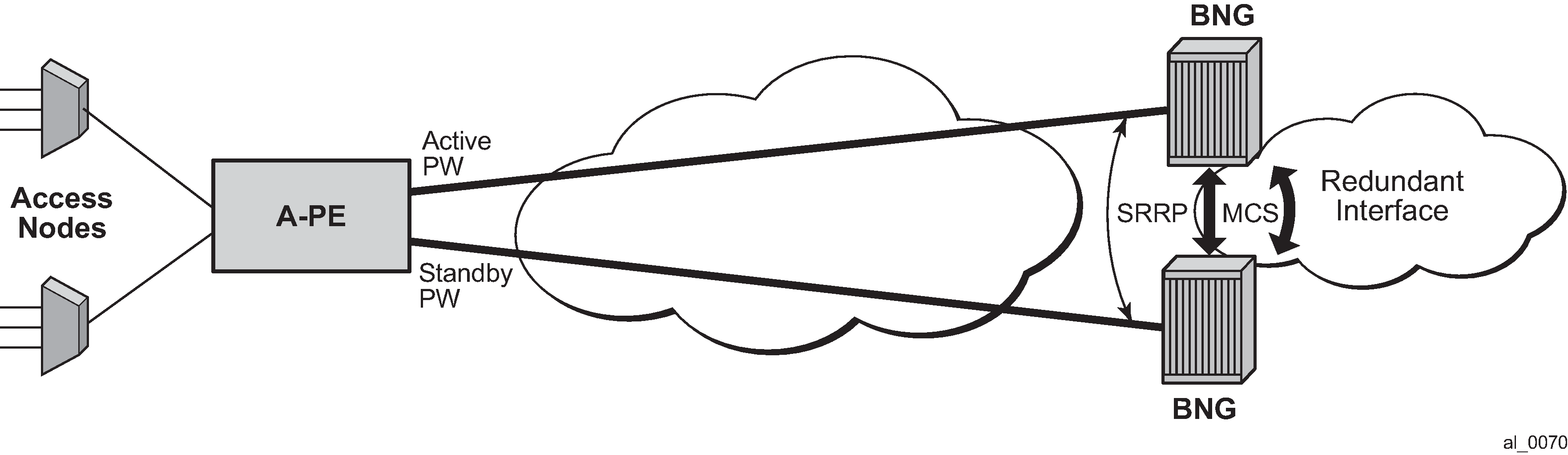
Sample configuration on an active BNG
config>
    pw-port 2 create
    exit

config>redundancy#
     multi-chassis
         peer 10.20.1.3 create
             source-address 10.20.1.2
                sync
                    srrp
                    sub-mgmt ipoe pppoe
                    port pw-2 sync-tag "tag2" create
                    exit
                    no shutdown
                exit
                no shutdown
            exit
        exit
     exit

config>service>ies#
       redundant-interface "redundant-interface" create
          address 10.10.30.2/24 remote-ip 10.10.30.3
          spoke-sdp 23:1000 create
             no shutdown
          exit
       exit
config>service#
    sdp 1 mpls create
       far-end 10.20.1.2
       ldp
       keep-alive
          shutdown
       exit
       binding
          port 1/1/1
          pw-port 2 vc-id 2 create
             vc-type vlan        #### default encaps-type dot1Q
             no shutdown
          exit
       exit
       no shutdown
    exit
config>service#
       subscriber-interface "subif" create
           address 10.11.1.2/16 gw-ip-address 10.11.1.1 populate-host-routes
                group-interface "grpif" create
                    authentication-policy "base_authpolicy"
                    redundant-interface "redundant-interface"
                    sap pw-2:1000 create
                        description "sap-grp-3"
                    exit
                    srrp 1 create
                        message-path pw-2:1000
                        no shutdown
                    exit
                    arp-host
                        host-limit overall 8000
                        min-auth-interval 1
                        no shutdown
                    exit
                exit
            exit
        exit
Sample configuration on a standby BNG
config>
    pw-port 2 create
    exit
config>redundancy#
     multi-chassis
         peer 10.20.1.2 create
             source-address 10.20.1.3
                sync
                    srrp
                    sub-mgmt ipoe pppoe
                    port pw-2 sync-tag "tag2" create
                    exit
                exit
                no shutdown
            exit
        exit
     exit
config>service>ies#
       redundant-interface "redundant-interface" create
          address 10.10.30.3/24 remote-ip 10.10.30.2
          spoke-sdp 32:1000 create
             no shutdown
          exit
       exit
config>service#
    sdp 1 mpls create
       far-end 10.20.1.2
       ldp
       keep-alive
          shutdown
       exit
       binding
          port 1/1/1
          pw-port 2 vc-id 2 create
             vc-type vlan        #### default encaps-type dot1Q
             no shutdown
          exit
       exit
       no shutdown
    exit
config>service#
       subscriber-interface "subif" create
           address 10.11.1.3/16 gw-ip-address 10.11.1.1 populate-host-routes
                group-interface "grpif" create
                    authentication-policy "base_authpolicy"
                    redundant-interface "redundant-interface"
                    sap pw-2:1000 create
                        description "sap-grp-3"
                    exit
                    srrp 1 create
                        keep-alive-interval 1
                        message-path pw-2:1000
                        no shutdown
                    exit
                    arp-host
                        host-limit 8000
                        min-auth-interval 1
                        no shutdown
                    exit
                exit
                group-interface "dummy" create
                    oper-up-while-empty
                exit
            exit
        exit
Sample configuration on A-PE
config>service>epipe#
     description "Default epipe description for service id 103"
     service-mtu 1492
     service-name "XYZ Epipe 103"
     endpoint "x" create
         standby-signaling-master
     exit
     sap 1/1/3 create
          description "Default sap description for service id 103"
     exit
     spoke-sdp 1:2 endpoint "x" create
          description "Description for Sdp Bind 1 for Svc ID 103"
          precedence primary
          no shutdown
     exit
     spoke-sdp 2:2 endpoint "x" create
          description "Description for Sdp Bind 2 for Svc ID 103"
          no shutdown
     exit
     no shutdown
VPLS-based aggregation service
With VPLS based aggregation service from A-PE, normal SRRP message exchange can take place between the active and standby BNGs. An active or standby decision and switch-over is based on the SRRP state. An SRRP instance is configured per group-interface corresponding to PW port. Fate-sharing groups (FSG) can be configured for a set of SRRP instances (for example, SRRP instances corresponding to PW ports sharing the same subnet). A standard oper-group grp-id should be configured with messaging SAPs for all PW ports that are in the same FSG, and monitor-oper-group grp-id should be configured under each SRRP instance in same FSG. Existing SRRP support defined in Triple-play services guide for ESM over regular group-interfaces and subscriber SAPs is applicable identically to ESM over PW ports and PW SAPs.
With ESM over PW, redundancy in the aggregation network based on MC-LAG between A-PE and dual BNGs is not supported.
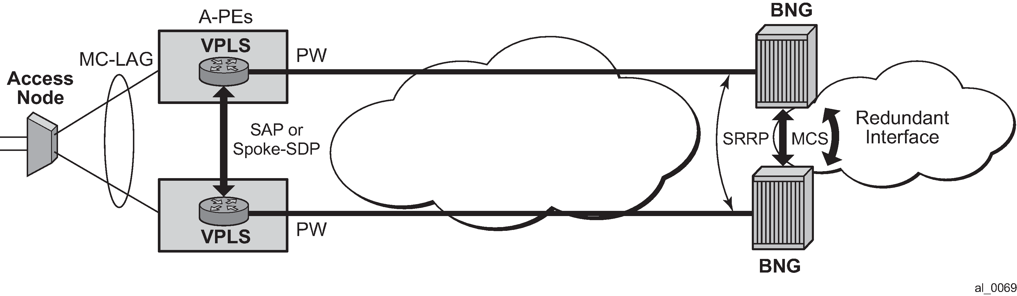
Sample BNG redundancy configuration with VPLS service on A-PE
config>
    pw-port 1 create
    exit

config>redundancy#
     multi-chassis
         peer 10.20.1.2 create
             source-address 10.20.1.3
                sync
                    srrp
                    sub-mgmt ipoe pppoe
                    port pw-1 sync-tag "tag1" create
                    exit
                exit
                no shutdown
            exit
        exit
     exit

 config>service>ies
       redundant-interface "red-1-1" create
           address 10.1.1.2/24 remote-ip 10.1.1.1
               spoke-sdp 1:1 create
                  no shutdown
               exit
           exit

       subscriber-interface "sub-1-1" create
            address 10.1.2.2/16 gw-ip-address 10.1.255.254 track-srrp 1
            address 10.2.2.2/16 gw-ip-address 10.2.255.254 track-srrp 2
            dhcp
                gi-address 10.1.2.2
            exit
            group-interface "grp-1-1-1" create
                 srrp-enabled-routing
                 arp-populate
                 dhcp
                     server 10.20.1.2
                     trusted
                     lease-populate 32767
                     client-applications dhcp ppp
                     gi-address 10.1.2.2
                     no shutdown
                 exit
                    authentication-policy "iesAuthPol"
                    redundant-interface "red-1-1"

                   sap pw-1:1.1 create
                       sub-sla-mgmt
                           def-sub-profile ‟sub_prof_1”
                           def-sla-profile ‟sla_prof_1”
                           no shutdown
                   exit
                   sap pw-1:4000.1 create
                        oper-group "1"
                   exit

                   srrp 1 create
                        gw-mac 00:00:5e:00:01:01
                        keep-alive-interval 50
                        message-path pw-1:4000.1
                        monitor-oper-group "1" priority-step 10
                        no shutdown
                    exit
                exit
Sample BNG redundancy configuration with VPLS service on A-PE
config>service
     customer 1 create
         description "Default customer"
     exit
     sdp 1000 mpls create
         far-end 10.20.1.2
         lsp "lsp_1"
         path-mtu 1600
         keep-alive
         no shutdown
      exit
      sdp 1002 mpls create
         far-end 10.20.1.3
         lsp "lsp_3"
         path-mtu 1600
         keep-alive
         no shutdown
      exit
      vpls 1 customer 1 create
          service-mtu 1600
          stp
          sap 1/1/2 create   // to Access-Node
          exit
        sap 1/1/3 create; //to A-PE2
        exit
          spoke-sdp 1000:1 create  // to BNG1
              no shutdown
          exit
          no shutdown

        exit
    exit
A-PE configuration with VPLS aggregation service (A-PE2)
config>service
     customer 1 create
         description "Default customer"
     exit
     sdp 1002 mpls create
         far-end 10.20.1.3
         lsp "lsp_2"
         path-mtu 1600
         keep-alive
         no shutdown
      exit

      vpls 1 customer 1 create
          service-mtu 1600
          stp
          sap 1/1/2 create   // to Access-Node
          exit
        sap 1/1/3 create; //to A-PE1
        exit
          spoke-sdp 1002:1 create  // to BNG2
              no shutdown
          exit
          no shutdown
        exit
    exit
Show commands related to active/standby pseudowire on dual BNGs
The following example shows SRRP status, subscriber host, and routing information about the active BNG (SRRP master state):
A:Dut-B>config>redundancy# show srrp 1
===============================================================================
SRRP Instance 1
===============================================================================
Description         : (Not Specified)
Admin State         : Up                 Oper State       : master
Preempt             : yes                One GARP per SAP : no
Monitor Oper Group  : None
System IP           : 10.20.1.2
Service ID          : VPRN 3
Group If            : grpif              MAC Address      : 1c:85:ff:00:00:00
Grp If Description  : N/A
Grp If Admin State  : Up                 Grp If Oper State: Up
Subscriber If       : subif
Sub If Admin State  : Up                 Sub If Oper State: Up
Address             : 10.11.1.2/16       Gateway IP       : 10.11.1.1
Redundant If        : redundant-interfa*
Red If Admin State  : Up                 Red If Oper State: Up
Address             : 10.10.30.2/24
Red Spoke-sdp       : 23:1000
Msg Path SAP        : pw-2:1000
Admin Gateway MAC   :                    Oper Gateway MAC : 00:00:5e:00:01:01
Config Priority     : 100                In-use Priority  : 100
Master Priority     : 100
Keep-alive Interval : 1 deci-seconds     Master Since     : 05/29/2012 07:22:26
Fib Population Mode : all
VRRP Policy 1       : None               VRRP Policy 2    : None
===============================================================================
* indicates that the corresponding row element may have been truncated.

A:Dut-B>config>redundancy# show service id 3 arp-host
===============================================================================
ARP host table, service 3
===============================================================================
IP Address      Mac Address       Sap Id              Remaining           MC
                                                      Time                Stdby
-------------------------------------------------------------------------------
10.11.1.11      00:80:00:00:00:01 [pw-2:11]           03h35m47s
10.11.1.12      00:80:00:00:00:02 [pw-2:12]           03h35m47s
-------------------------------------------------------------------------------
Number of ARP hosts : 2
===============================================================================

A:Dut-B>config>redundancy# show router 3 route-table 10.11.1.11
===============================================================================
Route Table (Service: 3)
===============================================================================
Dest Prefix[Flags]                            Type    Proto    Age         Pref
      Next Hop[Interface Name]                                   Metric
-------------------------------------------------------------------------------
10.11.1.11/32                                 Remote  Sub Mgmt 00h24m26s   0
       [grpif]                                                      0
-------------------------------------------------------------------------------
No. of Routes: 1
Flags: L = LFA nexthop available    B = BGP backup route available
       n = Number of times nexthop is repeated
===============================================================================
A:Dut-B>config>service>vprn#
The following shows SRRP status, subscriber host, and routing info in standby BNG (SRRP init state):
A:Dut-C>config>redundancy# show srrp 1
===============================================================================
SRRP Instance 1
===============================================================================
Description         : (Not Specified)
Admin State         : Up                 Oper State       : initialize
Preempt             : yes                One GARP per SAP : no
Monitor Oper Group  : None
System IP           : 10.20.1.3
Service ID          : VPRN 3
Group If            : grpif              MAC Address      : 1c:87:ff:00:00:00
Grp If Description  : N/A
Grp If Admin State  : Up                 Grp If Oper State: Down
Subscriber If       : subif
Sub If Admin State  : Up                 Sub If Oper State: Up
Address             : 10.11.1.3/16       Gateway IP       : 10.11.1.1
Redundant If        : redundant-interfa*
Red If Admin State  : Up                 Red If Oper State: Up
Address             : 10.10.30.3/24
Red Spoke-sdp       : 32:1000
Msg Path SAP        : pw-2:1000
Admin Gateway MAC   :                    Oper Gateway MAC : 00:00:5e:00:01:01
Config Priority     : 1                  In-use Priority  : 1
Master Priority     : 1
Keep-alive Interval : 1 deci-seconds     Master Since     : 05/29/2012 07:22:26
Master Down Interval: 0.000 sec (Expires in 0.000 sec)
Fib Population Mode : all
VRRP Policy 1       : None               VRRP Policy 2    : None
===============================================================================
* indicates that the corresponding row element may have been truncated.

A:Dut-C>config>redundancy# show service id 3 arp-host
===============================================================================
ARP host table, service 3
===============================================================================
IP Address      Mac Address       Sap Id              Remaining           MC
                                                      Time                Stdby
-------------------------------------------------------------------------------
10.11.1.11      00:80:00:00:00:01 [pw-2:11]           03h38m01s           Yes
10.11.1.12      00:80:00:00:00:02 [pw-2:12]           03h38m02s           Yes
-------------------------------------------------------------------------------
Number of ARP hosts : 2
===============================================================================
A:Dut-C>config>redundancy# show router 3 route-table 10.11.1.11
===============================================================================
Route Table (Service: 3)
===============================================================================
Dest Prefix[Flags]                            Type    Proto    Age         Pref
      Next Hop[Interface Name]                                   Metric
-------------------------------------------------------------------------------
10.11.1.11/32                                 Remote  Sub Mgmt 00h22m03s   0
       [redundant-interface]                                        0
-------------------------------------------------------------------------------
No. of Routes: 1
Flags: L = LFA nexthop available    B = BGP backup route available
       n = Number of times nexthop is repeated
===============================================================================
ESM on PXC-based PW ports
This section provides an example to configure PW port based capture SAP that is used in ESM. For more information about PXC Based PW ports, see the 7450 ESS, 7750 SR, 7950 XRS, and VSR Layer 2 Services and EVPN Guide.
PXC Configuration
The following is a PXC configuration example:
configure
   port-xc
      pxc 1 create
         port 1/1/1
         no shutdown
      pxc 2 create
         port 2/1/1
         no shutdown
With this configuration, ports 1/1/1 and 2/1/1 are auto-provisioned in hybrid mode operating as individual loopback ports. The SR OS system automatically creates a pair of sub-ports per PXC. Those sub-ports are, by default, are in the shutdown state, and must be explicitly enabled (no shutdown) by the operator.
configure
   port pxc-1.a
      shutdown
   port pxc-1.b
      shutdown

   port pxc-2.a
      shutdown
   port pxc-2.a
      shutdown
For redundancy purposes or increased bandwidth, the PXC sub-ports are aggregated in a LAG:
configure
    lag 1 create
        port pxc-1.a
        port pxc-2.a
    lag 2 create
        port pxc-1.b
        port pxc-2.b
FPE Configuration
A PW port is associated with PXC by an FPE configuration. FPE configuration facilitates creation of an internal tunnel over PXC. This tunnel is used to map the external PW to the PW port. For more information about FPE, see 7450 ESS, 7750 SR, 7950 XRS, and VSR Interface Configuration Guide.
The following is an FPE configuration example:
configure
    fwd-path-ext
        fpe 1 create
            path xc-a lag-1 xc-b lag-2
            pw-port
The association between xc-a/b (cross-connects) and LAG IDs is performed arbitrarily by the operator. For example, it can associate xc-a with lag-id 2 (which includes PXC sub-ports on the .b side) and xc-b with lag-id 1 (which includes PXC sub-ports on the .a side). However, the FPE always assigns the .a side of the pxc sub-ports to the transit side of the cross-connect, while the .b side of the pxc subport is assigned to the termination side of the cross-connect. See the PXC Based PW port sections in the 7450 ESS, 7750 SR, 7950 XRS, and VSR Layer 2 Services and EVPN Guide, for further information about transit/termination side of the cross-connect.
PW port creation
The PW port must be explicitly created in the SR OS, before mapping between PW and PW port can be performed.
pw-port 100 create
    encap-type qinq
SDP creation for the external PW
The following displays an SDP configuration for the external PW.
configure
    service
        sdp 1 create
            signaling tldp
            far-end 10.1.1.1
The PW can be static or dynamically signaled, with MPLS or GRE transport.
Mapping between the external PW and the PW port
The stitching of the external PW and PW port is configured through an Epipe in vc-switching mode.
configure
    service
        epipe 10 customer 1 vc-switching create
            spoke-sdp 1:100 create
            pw-port 100 fpe 1
Capture PW-SAP creation
PW-SAPs can be configured as capture SAPs. In this example, a capture PW-SAP with s-tag 3 is created on the pw-port 100.
configure
    service vpls 2 create
        sap pw-port-100:3.* capture-sap create
From here, ESM functionality is applied to the PW-SAP in the same manner as on any other regular SAP.
Cross-connecting SAPs to PW ports
In addition to PW termination, a PW port can become a terminating point for a regular SAP. For example:
configure
    service
        epipe 10 customer 1 vc-switching create
            sap 1/1/1:10.* create
            pw-port 100 fpe 1
In this example, the outer VLAN tag 10 in the payload is removed on ingress and the payload is delivered to the PW port where it can be mapped to a capture PW-SAP. This scenario allows traffic distribution from a single I/O port to different EMS termination points (anchor line cards) based on outer VLANs.
ESM multi-chassis redundancy with PXC-based PW ports and EVPN VPWS
Redundant BNGs with EVPN VPWS in the access area of the network rely on the EVPN Single-Active (SA) multihoming concept with PW ports in Ethernet Segments (ES). A PW port on one side in the ES is elected as the Designated Forwarder (DF) and the other side as the non-Designated Forwarder (NDF). The ES with the PW port as DF is operationally up, and conversely, the ES with the PW port as NDF is operationally down. The DF side is the active side while the NDF side is the standby side. SRRP, as part of subscriber management redundancy scheme, indirectly tracks ES states to determine which BNG side is active and which is standby. With multiple EVPN VPWS instances, the load is distributed between the redundant BNGs where one BNG can be active for one set of EVPN VPWS while the other BNG can be active for another set of EVPN VPWS instances. The operator can influence the selection of the active side (DF side) for each EVPN VPWS by configuring a higher preference number on the preferred DF side.
config>service>system>bgp-evpn>eth-seg>service-carving$ manual preference <number>
In a typical ESM environment, a PW port contains thousands of PW SAPs, with each PW SAP representing a subscriber. To minimize the outage time during failures, the operator (through configuration) can optionally keep those PW SAPs operationally up even if the underlying PW port is in the NDF state. This reduces the failover time otherwise required to bring all the PW SAPs operationally up.
The SRRP state must transition into a standby state on the NDF side even if the PW-port is operationally up. To achieve this, the SRRP messaging PW SAP goes through an oper-group that tracks the state of the ES, whose operational state is up on the DF side and down on the NDF side
The basic concept of this approach, where the messaging SRRP PW-SAP is tracking the state of the ES, is shown in BNG multi-chassis redundancy with EVPN VPWS . There are two key concepts introduced:
The oper-up-on-mhstandby CLI flag ensures that the PW port is operationally up even while it is the NDF.
The SRRP messaging SAP is tracking the state of the corresponding ES through an oper-group (‟demo-ES2”). This ensures that the SRRP follows the activity state of the EVPN VPWS, while the PW port remains operationally up on both BNGs (active and standby).

Within an SR node, a collection of separate entities work together to detect a failure in the network and divert the traffic around it. Those entities are:
ESM where subscribers are synchronized between the chassis
-
EVPN VPWS in the access area of the network
-
Routing that is advertising subscriber routes into the network
-
Oper-groups used to interconnect operational states between the entities
-
Various network failure detection mechanisms such as BFD to quickly detect failure path between BGP peers
The following is a detailed description of the setup with a single EVPN VPWS and two BNGs (BNG multi-chassis redundancy with EVPN VPWS ).
EVPN VPWS is configured as SA) multihoming. SA is crucial in ESM as it drives the SRRP state which must always be in an active or standby state between the redundant pair of BNGs.
BNGs are connected to the AN through an EVPN VPWS.
One BNG in the EVPN is selected as the DF (BNG1), the other BNG (BNG2) is the NDF.
BNG2 bring its ES down.
Only BNG1 advertises its AD route toward the access node.
Consequently, the AN does not send any traffic to BNG2 (NDF). Instead, the AN sends all traffic only to BNG1 (DF).
The ES is part of an oper-group (OG) which is monitored from the ESM side.
The stitching Epipe on BNG2 does not change its status. Neither does the PW port in it. The PW port stays up despite the MHStandby flag being raised. Normally, the MHStandby flag would cause the PW port to go down, but because of the oper-up-on-mhstandby configuration option, this behavior is overridden.
ESM subscribers are synchronized between the chassis through MCS and are using SRRP on the access side. With EVPN in the access, SRRP is not relying on its own keepalives to check the health of the network path, but instead, it follows the state of the PW port or the ES. If the PW port is operationally up, the messaging PW SAP is up, and therefore the SRRP is active. Conversely, if the PW port is operationally down, the messaging PW SAP is down and consequently SRRP is in the backup state. This is the expected behavior when the EVPN MPLS destination (network bind) goes down.
However, in the SA multihoming scenario, when the EVPN MPLS destination is not down, the PW port remains up even if the PW port is an NDF. Instead of relying on the PW port state, the SRRP messaging PW SAP monitors the state of the ES through an oper-group. When the oper-group changes its state to down, so does the SRRP messaging PW SAP, which then forces the SRRP into an INIT state (which is equivalent to a standby state).
On the network side, the state of the SRRP controls the advertisement of the subscriber IP routes into the network. Subscribers routes are advertised with a lower cost from the active SRRP node than they are from the standby SRRP node.
The solution described above protects against failures in the access part of the network or BNG node failure. Optionally, network side ports can be placed in an oper-group that can be monitored from the EVPN side. This can be used to protect against network port failures.
Logical Link Identifier (LLID)
This feature enables service providers to track subscribers based on a virtual-port known as logical line ID (LLID). The LLID (an alphanumeric string) is a logical identification of a subscriber line. Mapping of physical line of a subscriber to LLID is performed by pre-authentication with a separate AAA server than the AAA server used for authenticating the subscriber session during normal access authentication.
LLID serves the purpose of abstracting the physical line of the user from the ISP. If the user moves to a new physical line, the RADIUS server database maintaining the physical line of the subscriber to LLID is updated. Because a subscriber’s LLID remains same regardless of subscriber’s physical location, using LLID gives service provider a stable and secure identifier for tracking subscriber.
The local user database assigned to the PPPoE node under the group interface can have both a pre-authentication policy and an authentication policy. The purpose of the pre-authentication policy is to retrieve the LLID from the AAA server. The pre-authentication only extracts the calling-station-id attribute (0x31) which is used as the LLID, anything else returned during pre-authentication are simply ignored. If the pre-authentication is missing the LLID, the session moves on to the authentication policy. In the authentication policy that follows, it is possible to use the LLID as the calling-station ID.
It is possible to convey LLID from the LAC to the LNS. The LLID is retrieved through PPPoE pre-authentication where the returned RADIUS attribute calling station ID is used as the LLID. This LLID is selectable attribute in L2TP as a calling-number (AVP 22) to be passed from LAC to LNS. At the LNS, the subscriber calling station number is retrieved from AVP 22 and can be included as an attribute during authentication.
PADI authentication policy for managed SAP (MSAP)
The PADI Authentication Policy feature enables PADI authentication that retrieves MSAP parameters before pre-authentication and PPPoE authentication.
With this feature, authentication occurs in the following manner.
PADI authentication and MSAP authorization:
A capture SAP receives a PPPoE PADI packet.
A check verifies that the LUDB is configured as pppoe-user-db on the capture SAP.
The LUDB must be configured on the capture SAP. Without the LUDB specified, the existing functionality is performed for MSAP creation.
The LUDB host entry is matched to the entry that has the PADI authentication policy.
RADIUS authentication and MSAP authorization occurs.
An MSAP is created if the authentication policy is not configured for PAP/CHAP.
(Optional) LLID pre-authentication:
Look up the LLID pre-authentication policy under the LUDB host entry.
Perform RADIUS pre-authentication to obtain an LLID.
LCP authentication and L2TP tunnel authorization:
Trigger RADIUS authentication defined by the authentication policy configured in the LUDB host entry in the previous step.
Create the MSAP, finish the LCP authentication with the PPP client, and establish an L2TP tunnel/session.
Triple authentication with MSAP authentication policy shows triple authentication with MSAP authentication policy.
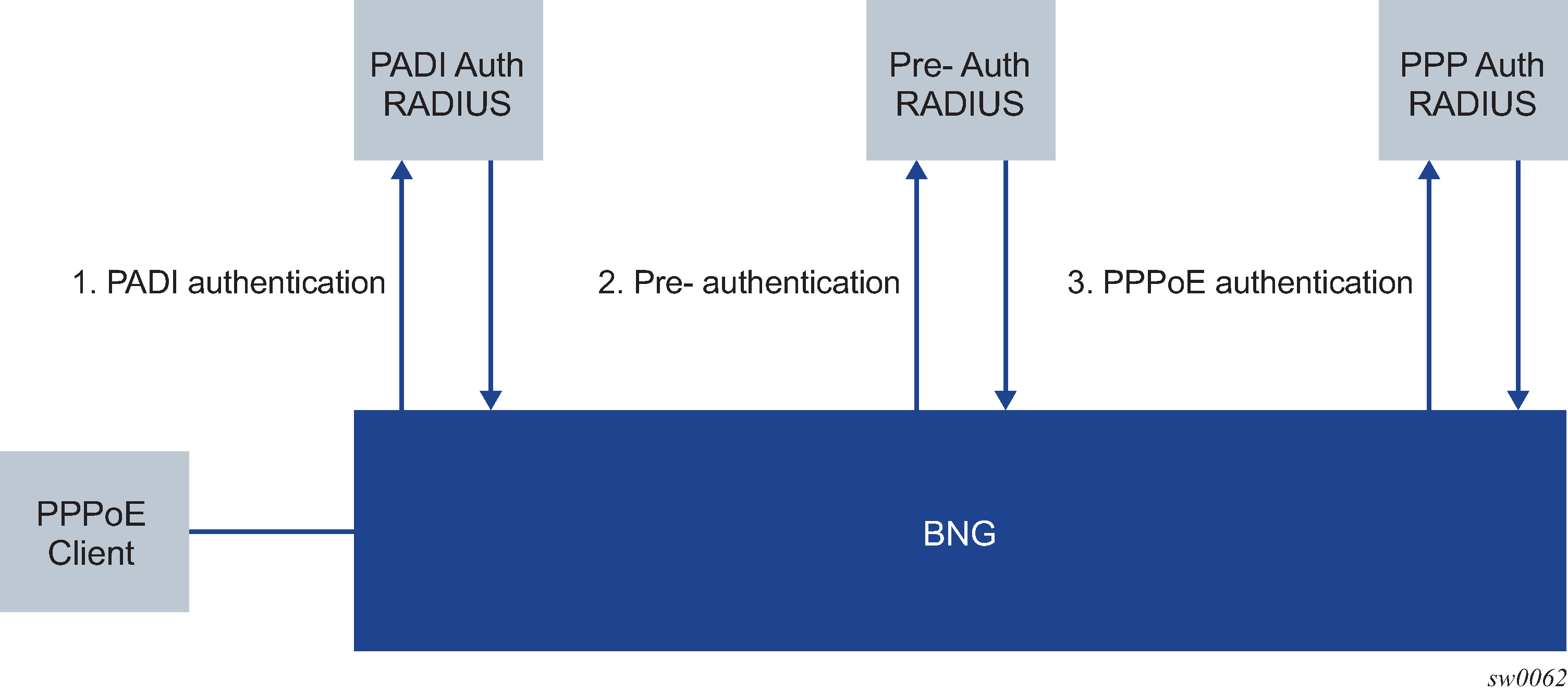
The CLI command config>subscr-mgmt>loc-user-db>ppp>host>padi-auth-policy configures a PADI authentication policy used for PADI authentication with MSAP authorization as shown in the CLI example below:
configure
    subscriber-mgmt
        local-user-db ‟ludb-1” create
            ppp
                host ‟default” create
                    padi-auth-policy ‟padi_auth”
Open authentication model for DHCP and PPPoE hosts
Terminology
LUDB
Local User Database configured within the 7450 ESS and 7750 SR.
IP Address Assignment with DHCP Relay
IP address assignment request (DHCP or IPCP) from the host is relayed to an internal or external DHCP server. A gi-address must be present in this relayed request while the pool name is optional. The internal DHCP server may select the IP address from is local pool based on the gi-address or based on the pool-name present in the request. The IP address selection method is configuration dependent. Third party DHCP servers may consider additional fields in IP address selection process (mac address, circuit-id, and so on).
IP Address Assignment with DHCP Proxy
A preconfigured IP address in LUDB or RADIUS server is handed out to the host using a DHCP proxy function. This proxy function responds natively using DHCP protocol to the IPoE host. Although PPPoE hosts are not utilizing DHCP protocol, the DHCP proxy functionality within the server is still needed for successful IP address delegation to PPPoE hosts.
Prioritization of authentication sources
ESM parameters (ESM strings and other IP parameters) obtained during authentication and re-authentication phases are combined from various sources with a specific preference order as follows:
ESM Python (set.esm function)
Diameter/Gx
LUDB
RADIUS
Diameter/Nasreq
LocalAddressAssignment
GTP
DHCP
DHCP parameters that came from standard DHCP options returned by the DHCP server directly
Information extracted from options (strings-from-options). This is applicable for IPoE and PPPoE (DHCP client) that use a local DHCP server with LUDB.
DHCP ACK Python
defaults, if any
For example, if the same ESM parameter is provided through both authentication sources, LUDB and RADIUS, the ESM parameter from LUDB always overrides the ESM parameter obtained from RADIUS.
SR OS allows the priority of LUDB and RADIUS sources to be reversed. This prioritization of authentication sources, where RADIUS is granted priority over LUDB, ensures that parameters from LUDB are used as a backup, only in cases where the same ESM parameters are not provided by RADIUS.
The settings that allow swapping of the LUDB and RADIUS priorities as authentication sources are configured on the system level as follows.
Classic CLI:
subscriber-mgmt
   authentication-origin
       [no] priority <id> source <string>
   exit
exit
The only accepted configuration option is id 3 and RADIUS as the source string. This configuration moves RADIUS to position 3 and shifts everything from the previous position 3 downward.
The defaults are restored by using the no form of the priority command.
The active order of priorities can be displayed in the output of the show>subscr-mgmt>authentication-origin command:
*A:cses-V26>config>subscr-mgmt>auth-orig# show subscriber-mgmt authentication-origin
===============================================================================
Authentication Origins
===============================================================================
Priority                         Source
-------------------------------------------------------------------------------
1                                python
2                                diameterGx
3                                ludb
4                                radius
5                                diameterNasreq
6                                localAddressAssignment
7                                gtp
8                                dhcp
-------------------------------------------------------------------------------
Number of Authentication Origins : 8
===============================================================================
*A:cses-V26>config>subscr-mgmt>auth-orig# priority 3 source radius
*A:cses-V26>config>subscr-mgmt>auth-orig# show subscriber-mgmt authentication-origin
===============================================================================
Authentication Origins
===============================================================================
Priority                         Source
-------------------------------------------------------------------------------
1                                python
2                                diameterGx
3                                radius
4                                ludb
5                                diameterNasreq
6                                localAddressAssignment
7                                gtp
8                                dhcp
-------------------------------------------------------------------------------
Number of Authentication Origins : 8
===============================================================================
*A:cses-V26>config>subscr-mgmt>auth-orig#
The following describes the configuration logic where both LUDB and RADIUS are accessed during authentication phase:
LUDB is referenced under the capture SAP (if the capture SAP is deployed) and the group interface (DHCP, DHCP6, or PPPoE).
The authentication policy is referenced in LUDB (and not under the capture SAP and group interface).
With this approach, LUDB is accessed first and subscribers can be authenticated based on generic criteria, such as a range of VLANs or a default user. The ESM parameters obtained in this step are stored.
After LUDB authentication, RADIUS is accessed when authentication on subscriber-specific authentication fields is performed (for example, based on a username, circuit-id, MAC address, and so on). During this RADIUS authentication phase, another set of ESM parameters more tailored for the specific user is obtained, effectively overriding the overlapping parameters from LUDB.
Authentication source — session versus host ESM Model
For IPoE host-based deployments, such as when the ipoe-session is disabled (meaning that clients are treated as hosts instead of sessions), the re-authentication option in the authentication policy must be enabled when RADIUS is prioritized over LUDB as the authentication source. Enabling re-authentication is only required in IPoE host-based deployments and not required for IPoE or PPPoE sessions.
No authentication
IPoE and PPPoE v4/v6 hosts on static SAPs can be instantiated without the need to access LUDB or RADIUS server. In this case, the default subscriber host parameters (sla-profile, sub-profile, subscriber-id) must be provisioned statically under the SAP. The IP address assignment is provided by internal or external DHCP server. The IP address selection on the router based DHCP server is based on the gi-address while third party DHCP servers may provide additional means to select the IP address (mac-address, circuit-id, and so on).
A DHCP pool name cannot be provided by an SR-series router DHCP relay agent, because the LUDB and RADIUS are not used.
This model does not support IP address delegation by DHCP Proxy function because there is no LUDB or RADIUS server available that can supply pre-configured IP address.
Host instantiation without LUDB or RADIUS access on dynamic VLANs (capture SAP and consequently mSAP) is not supported.
LUDB only access
Subscriber-host authentication, identification and IP address assignment can be performed by LUDB without the need to access the RADIUS server.
The LUDB is normally configured under the group-interface>ppp/dhcp hierarchy and can provide subscriber-identification parameters as well as IP addressing parameters:
Pool names for DHCP relay function (IPv4, IPv6 IA-NA, IPv6 IA-PD)
Fixed IP addresses – IPv4, IPv6 IA-NA, IPv6 IA-PD and IPv6 SLAAC prefix.
In case of capture SAP, the LUDB name configured under the capture SAP must match the LUDB name under the group-interface>dhcp/ppp hierarchy. If the LUDB names do not match, the subscriber-host instantiation fails.
LUDB access by DHCPv4 server
If the IPv4 addressing assignment is facilitated by the DHCPv4 relay and an internal DHCPv4 server, the DHCPv4 server itself can query the LUDB for IPv4 address information. LUDB can provide a v4 pool name and IPv4 DHCP options to the DHCPv4 server or it can instruct it to use the gi-address as the IPv4 address selection mechanism.
ESM strings can also be provided by LUDB queried by the DHCPv4 server.
If LUDB access by DHCPv4 server is provided in addition to other authentication means (another LUDB under the group-interface, or RADIUS server), the ESM strings from the LUDB under the grp-interface or from the RADIUS server has priority over the ESM strings configured under the LUDB accessed by the DHCPv4 server. On the other hand, the IPv4 addressing information has the highest priority from the LUDB accessed directly by the DHCPv4 server.
Accessing LUDB directly by DHCPv4 server should be used in rare and exceptional cases.
LUDB access under the group-interface, possibly complemented by the RADIUS server provides necessary means for subscriber-host instantiation in majority of use cases.
RADIUS only access
Like LUDB-only access, RADIUS server can provide all the necessary information for subscriber-host instantiation, including the IP addressing parameters (pool names or IP addresses/prefixes). Authentication-policy which defines the RADIUS access must be applied to the group-interface.
In case of capture SAP, the authentication policy must be applied under the capture SAP. This authentication policy name must match the authentication policy name that is configured under the group-interface. Otherwise, the host instantiation fails.
Consecutive access to LUDB and RADIUS
LUDB and RADIUS access can be combined during subscriber-host instantiation phase.
Configuration-wise, LUDB must be referenced under the group-interface>dhcp/ppp/pppoe hierarchy (and possibly under the capture SAP), while the authentication-policy is specified within the LUDB. In this fashion, LUDB access is followed by RADIUS access. The subscriber-host parameters retrieved from both sources are combined with LUDB parameters being prioritized over RADIUS parameters in case that both sources return the same parameters.
If LUDB and authentication policy are configured simultaneously under the group-interface (and possibly under the capture SAP), the RADIUS authentication policy evaluates and LUDB is ignored.
RADIUS fallback
If RADIUS server is not accessible (non-responsive), the host instantiation phase can be:
Terminated if there is no fallback action within authentication policy specified.
Continued within LUDB if the fallback action within the authentication-policy references LUDB.
Continued without any response from RADIUS. Subscriber-host is instantiated if defaults parameters are statically configured or the instantiation fails if the defaults are not available.
The fallback action takes effect after the preconfigured RADIUS timeout period expires.
RADIUS fallback is not supported for DHCPv6 hosts for non-IPoE sessions but is supported for IPoE sessions.
Flexible subscriber-interface addressing (unnumbered subscriber-interfaces)
Terminology
Subscriber host
A representation of an external host requesting a service. Each such host is fully instantiated within the 7450 ESS and 7750 SR for the purpose of providing traffic control and billing services (for example, QoS, filtering, antispoofing, accounting). The external hosts may represent variety of devices such as regular PCs, STBs, residential gateways, CPEs, VoIP devices. In most cases, the external host runs a DHCPv4/v6 or PPPoEv4/v6 client. DHCP and PPPoE initiation messages from such clients triggers host instantiation within the router. For this the subscriber host term can be interchangeably used with a term DHCP client or PPPoE client.
Flexible subscriber-interface addressing for IPOE/PPPoE v4/v6 subscribers
In various wholesale or retail environments, the wholesale provider that own the 7450 ESS and 7750 SR BNG does not know the IP addresses that the retailers assigns to their clients in advance. For this reason, wholesaler’s BNG must accept any IP address from retailers and consequently pass it to the client during subscriber-host initiation phase.
Use case for flexible IP addressing model shows a use case for flexible IP addressing mode.
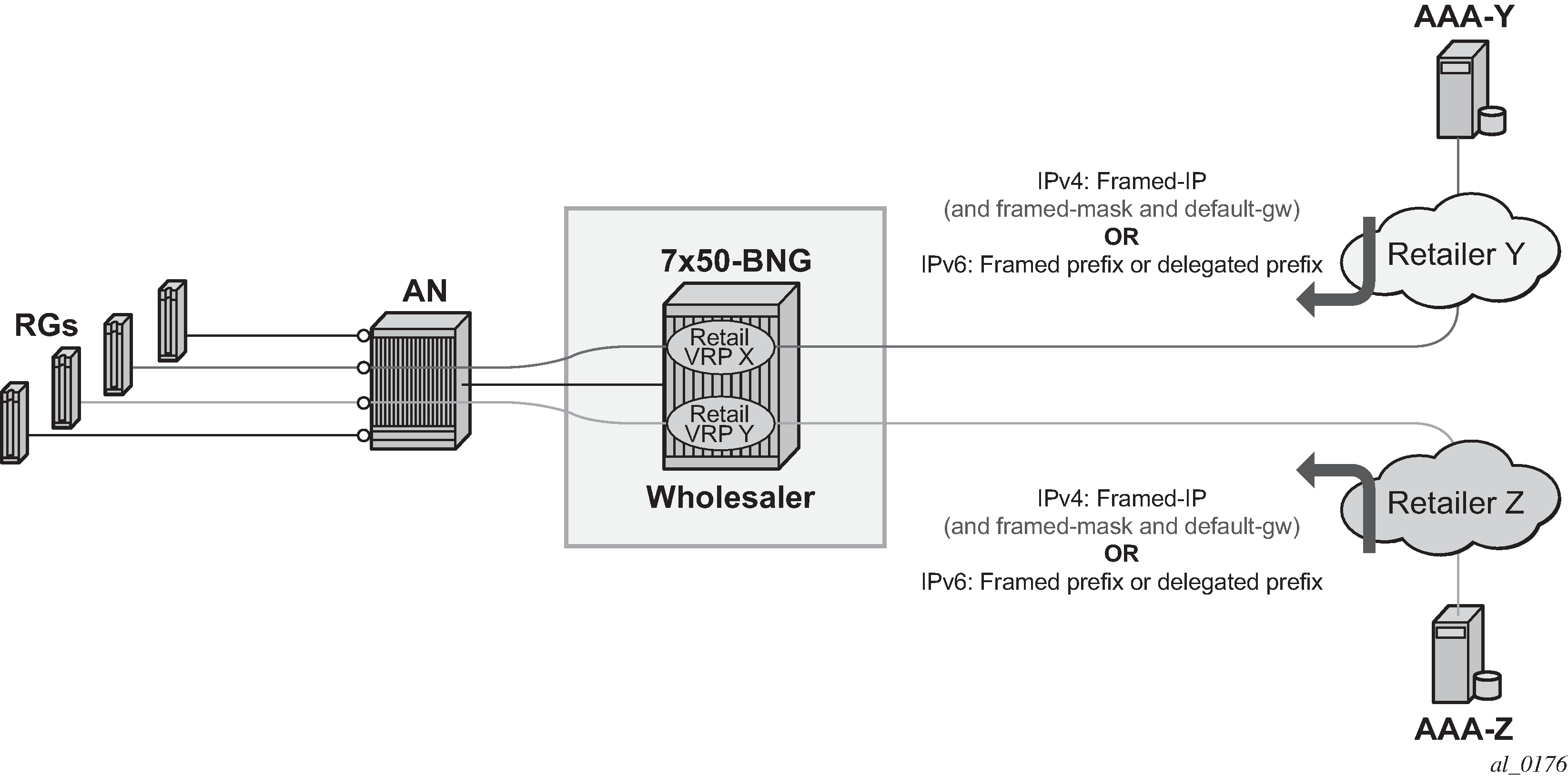
Flexible addressing of the subscriber-interface assumes two deployment scenarios:
Subscriber-interface is unnumbered
For example, there is no explicit assigned IP address. Instead the subscriber-interface borrows the IP address from an existing interface that is operationally UP and is located in the same routing instance (router or vprn).
An interface must have an IP address assigned to be operationally UP. Therefore, an unnumbered subscriber-interface must reference another existing interface that is operationally UP in the same routing instance. The subscriber-interface borrows the IP address from the referenced interface.
In this case any IP address can be assigned to the subscriber host under the unnumbered subscriber-interface. The subscriber IPv4 address is installed in the FDB as /32 route while IPv6 address is installed as an entry of the length anywhere between 64 and 128 bits.
Subscriber-interface is numbered
The IP address/prefix is explicitly configured and solely owned by the subscriber-interface.
In this case, all subscriber IP addresses/prefixes that fall under the subnet/prefix dictated by the configured subscriber-interface IP address/prefix is directly aggregated under the subscriber-interface subnet. They occupy a single entry in the FDB. The rest of the subscriber hosts with IP addresses/prefixes that fall outside of the configured range are installed in the FDB as individual entries (/32 for IPv4 and an entry of the length anywhere between 64 and 128 bits for IPv6 hosts).
Default gateway in IPv4 flexible addressing
In scenarios where subscriber host IPv4 address lies within the configured subscriber-interface subnet, the default-gw IPv4 address for the host is one of the subscriber-interface IPv4 addresses. In this case, the service provider is aware of the IPv4 addressing scheme in the BNG and supplies the DHCP client with the appropriate default-gw IPv4 address by LUDB, RADIUS or DHCP server (in that order of priority).
In scenarios where the retail service provider wants to maintain independence from the IPv4 addressing scheme deployed in the BNG (that is controlled by wholesaler), the retailer can always supply its own IPv4 address, the subnet mask and the default-gw IPv4 address. But if the default-gw IPv4 address and subnet mask is not supplied by the retailer, then they are auto-generated by the BNG. After the default-gw IPv4 address is auto-generated, it is sent to the requesting DHCP client by DHCP offer in option 3 (RFC 2132, Router Option, section 3.5). There is no additional configuration needed for this action. The BNG automatically detects whether the default-gw IPv4 address is supplied by LUDB, RADIUS or DHCP server and acts correspondingly.
The default-gw IPv4 address is auto-generated based on the assigned IPv4 address/mask by setting the last bit of the assigned host IPv4 address to binary 01 or binary 10. For example if the subscriber host’s assigned IPv4 address is 10.10.10.10 255.255.255.0, then the default-gw IPv4 address is set to 10.10.10.1. If the assigned IPv4 address is 10.10.10.1 255.255.255.0, then the auto-generated default gateway IPv4 is set to 10.10.10.2.
The default gateway IPv4 address always must be within the subscriber’s subnet. If it is not, the behavior may be inconsistent. For example:
RADIUS (or DHCP) returns IP@, mask and def-gw:
-
IP 10.10.10.1
-
Def-gw 10.10.0.254
-
Subnet mask 255.255.255.0
The subscriber is successfully instantiated in the BNG, but the client may not ARP for a default-gw outside of its configured subnet. Whether the client does or does not ARP for a default-gw outside of its configured subnet depends on the implementation in the RG and CPE.
RADIUS returns IP@ and subnet mask.
In this case the auto-generated default-gw IPv4 address is always within subscriber’s subnet.
Flexible IPv4 addressing with auto-generated default-gw is supported only in Routed Central Office (RCO) model with routed residential gateways (RGs) or CPEs. In RCO model with bridged residential gateways or CPEs, the default-gw IPv4 addresses and the assigned IPv4 addresses may overlap. After the IPv4 address of the default-gw is auto-generated, it is possible that the second host behind the bridged residential gateway or CPE is assigned the same IPv4 address as the IPv4 address of the default gateway of the first host. Such hosts would not be able to communicate with outside world.
For example:
RADIUS or DHCP server assigns IPv4 address and subnet mask to the first host in a bridged environment:
IP1: 10.10.10.1
Auto-generated default-gw IPv4 address: 10.10.10.2
Because the RADIUS and DHCP server are not aware of the auto-generated default-gw, they may assign the following IPv4 address to the second host that comes on-line:
IP 2: 10.10.10.2 (same IPv4 address as the default-gw IPv4 address of the first host)
Auto-generated default-gw IPv4 address: 10.10.10.1
Now the first host forwards all traffic outside of the configured subnet to the second hosts which discards this traffic, effectively rendering this operation model non-deployable. And the other way around.
IPv4 subnet sharing
Subnet sharing between the hosts in flexible IPv4 addressing model is supported. In other words, in flexible IPv4 addressing model the operator can assign all IPv4 addresses (minus one, the default-gw IPv4 address) from a specific subnet. In this fashion, all subscribers (routed RGs or CPEs) within a single subnet can share the same default gateway.
For example, if the operator owns the IPv4 subnet 10.10.10.0/24, then one IPv4 address can be set aside for the default-gw (for example 10.10.10.254) and the remaining addresses can be assigned to the subscriber (routed RGs or CPEs). An example would be:
RG1: IP=10.10.10.1/24 def-gw 10.10.10.254
RG2: IP=10.10.10.2/24 def-gw 10.10.10.254
RG3: IP=10.10.10.3/24 def-gw 10.10.10.254
:
RG100: IP=10.10.10.100/24 def-gw 10.10.10.254
The subnet sharing is also supported in conjunction with auto-generated default-gw IPv4 address. The implication of this is that the IPv4 address of the default-gw can collide with the same IPv4 address already assigned to an existing subscriber. This is not an issue for routed RGs or CPEs because the BNG always answers ARPs for the IPv4 address of the default-gw with its own MAC address. However, local-proxy ARP functionality in the 7450 ESS and 7750 SR BNG must be enabled to support this.
This behavior can be further clarified with the following example.
Let’s assume that we have scenario with two routed RGs:
RG-1, IP=10.10.10.0/24, default-gw IP=10.10.10.1
RG-2, IP=10.10.10.1/24, default-gw IP=10.10.10.0
After RG-1 ARPs for its default gateway of 10.10.10.1, the BNG replies with its own MAC address.
Now that host RG-1 has resolved ARP for it default-gw (MAC address pointing to the router), it can send traffic to the outside world by the BNG. When such traffic arrives to the router, the destination IPv4 address of the received packet determines the forwarding decision within the router. If the destination IPv4 address matches the IPv4 address of any subscriber (RG) instantiated within the system, the traffic is forwarded to the that RG. This also includes the case where the destination IPv4 address is the default-gw IPv4 address (10.10.10.1), which represents just another RG within the router. The traffic is consequently passed from RG-1 by 7450 ESS and 7750 SR to RG-2.
IPv4 subnet mask auto-generation
The subnet mask corresponding to the IPv4 address assigned to the subscriber is auto-generated in case that the IPv4 addressing authority (LUDB, RADIUS or DHCP server) does not supply it. The subnet mask is derived from the IPv4 address of the subscriber and possibly the default-gw IPv4 address and it is the smallest subnet that contains both, the IPv4 address of the subscriber and the default-gw.
For example, if the RADIUS received IPv4 address is 10.10.10.138 and the received default –gw IPv4 address is 10.10.10.170, then the subnet mask is auto-generated and set to 255.255.255.192 (/26).
138 = 10001010
170 = 10101010
192 = 11000000
In case that neither the subnet mask nor the default-gw are returned, then both would be auto-generated:
Subnet mask would be set to /31
Default-gateway which must belong to the subscriber’s subnet would be set to 10.10.10.139.
In cases where the host IPv4 address and the default-gw are directly supplied by the addressing authority but the subnet mask is missing, the subnet mask auto-generation may cause the host part of the default-gw IPv4 address to become a broadcast IPv4 address. If this is an issue, then it can be avoided by directly providing the subnet mask by the addressing authority.
local-proxy-arp and arp-populate
local-proxy-arp and arp-populate are two commands that are relevant only to IPoEv4 hosts.
The local-proxy-arp command ensures that the router answers ARP Requests with its own MAC address for any active IPv4 address under the subnet on which the ARP request arrived. The active IPv4 address is considered the one that is assigned to an already instantiated hosts or the default-gw (even auto-generated).
In absence of local-proxy-arp command, the only ARP Request that the router’s answer is the one for the statically configured IPv4 addresses of the subscriber-interface. In flexible IPv4 addressing, the IPv4 address of the default-gw does not necessarily match any of the configured subscriber-interface IPv4 addresses. The ARP Request for such default-gw IPv4 address would go unanswered. Consequently, the subscriber hosts would not be able to communicate with outside world. Therefore, the flexible IPv4 addressing requires that the local-proxy-arp command is configured.
The arp-populate command disables dynamic learning of ARP entries (IPv4<->MAC mapping) on an interface based on the ARP protocol. In this case, the ARP table is populated based on the DHCPv4 lease state table which contains IPv4<->MAC mappings obtained through DHCP processing during the host instantiation phase. Arp-populate functionality is highly desirable in case of flexible IPv4 addressing.
When the arp-populate command is disabled the ARP entries are dynamically learned based on the ARP protocol. This, in conjunction with flexible IPv4 addressing may cause issues. Consider the following example:
The subscriber host is instantiated in the 7450 ESS and 7750 SR
The subscriber interface is unnumbered
The ARP table does not contain an ARP entry for the subscriber-host
In this case, downstream traffic toward the subscriber host triggers the router to send ARP request for the subscriber host IPv4 address. The router must know the MAC address of the subscriber-host to forward traffic. Because the subscriber interface is unnumbered, the source IPv4 address of the ARP request is unknown and consequently, the ARP request are not sent. As a result, downstream traffic is dropped.
However, the above example is an unlikely scenario. If the subscriber host sends the ARP request for the default-gw first, the router would create an entry in the ARP table for it and the issue would be resolved. This is the most likely outcome because the subscriber host always tries to initiate communication with the outside and therefor ARP for the IPv4 address of the default-gw (which is a 7450 ESS and 7750 SR).
Gi-address configuration consideration
With flexible IPv4 address assignment, the gi-address can be configured as any IPv4 address that is already assigned to an interface (loopback interface, regular interface attached to physical port or subscriber interface) within the same routing instance (VRF or GRT).
PPPoE considerations
PPPoE subscriber hosts do not have the concept of default-gw. Consequently, the default-gw auto-generation concept does not apply to PPPoE hosts.
IPoEv4 considerations
Unnumbered subscriber hosts are instantiated on a subscriber interface that is configured to be unnumbered or to allow unmatching subnets. The IPv4 address of an unnumbered host falls outside the subnets configured on the subscriber interface.
By default, Subscriber Host Connectivity Verification (SHCV) ARP requests for unnumbered hosts are sent with an all-zeros (0.0.0.0) source IP address (also known as the sender IP address). The source IP address can be changed to any unicast IPv4 address in the SHCV policy:
configure subscriber-mgmt
        shcv-policy "shcv-policy-1" create
            layer-3
                unnumbered-source-ip 192.0.2.1
            exit
        exit
IPoEv6 considerations
The default-gw for IPoEv6 hosts is link-local IPv6 address. Because this address is always present, there is no need for auto-generation during the subscriber instantiation time.
SLAAC hosts are installed as /64 entries, the length of the installed DHCP-PD prefix is dictated by the prefix-length and the DHCP-NA hosts are installed as /128 entries.
General configuration guidelines for flexible IP address assignment
Flexible IP addressing for IPoE/PPPoE v4 and v6 hosts is by default disabled. In other words, the subscriber hosts are instantiated in the BNG with ability to forward traffic only if their assigned IP addresses belong to one of the configured subnets/prefixes that are associated with the subscriber-interfaces. IPv4 and IPv6 cases are be examined separately:
IPv4:
By default, IPoE and PPPoE subscriber host creation fails in the following two cases:
The subscriber-interface does not have an IPv4 address configured, and therefore it is operationally down. This configuration is also known as unnumbered subscriber-interface.
The subscriber-interface does have an IPv4 address configured but the IPv4 address assigned to the subscriber host itself is outside of the subscriber-interface configured subnets. In such case, the host is instantiated, but the forwarding is disabled.
Subscriber host instantiation and forwarding can be explicitly enabled for both cases above with flexible IP addressing functionality.
For case 1, this can be achieved by borrowing an IP address for the subscriber-interface from any interface that is operationally up within the routing context. This functionality can be enabled with the configure service ies | vprn <service-id>subscriber-interface <ip-int-name> unnumbered <ip-int-name | ip-address> command.
To enable forwarding for the subscribers whose IP address falls outside of the configured subnet under the subscriber-interface (case 2), the configure service ies | vprn <service-id> subscriber-interface <ip-int-name> allow-unmatching-subnets command must be entered.
The above commands (unnumbered and allow-unmatching-subnets) are mutually exclusive. In addition, the unnumbered command can be configured only if the subscriber interface does not have an IP address already configured. Otherwise the execution of this command fails.
In both of these cases the host is installed in the routing table as /32.
IPv6:
For IPv6 there is a single command that enables flexible IP addressing for both cases:
IPv6 prefixes are not configured under the sub-if>ipv6 node
IPv6 prefixes are configured but the actual address or prefix assigned to the subscriber (by DHCP, LUDB or RADIUS) is outside any prefix that is configured under the sub-if>ipv6 hierarchy.
This single command is configure service ies | vprn <service-id> subscriber-interface <ip-int-name> ipv6 allow-unmatching-prefixes.
To summarize, the following scenarios are possible:
PPPoEv4
An IPv4 address under the subscriber-interface is configured
By default, hosts outside of the sub-intf subnet are instantiated but they are in a non-forwarding-state. Traffic is dropped.
allow-unmatching-subnets is configured. This command is allowed only if subscriber-interface has also configured its own IPv4 address(es). In this case the IP address for IPCP negotiation is one of the sub-intf addresses. Hosts outside of the sub-intf subnets are instantiated and forwarded.
The unnumbered <ip-address | ip-int-name> command is not allowed in this scenario.
An IPv4 address under the subscriber-interface is not configured
By default, the subscriber-interface is operationally down. Subscribers cannot be instantiated.
The allow-unmatching-subnets command has no effect because a subscriber-interface does not have an IPv4 address configured and is therefore operationally down. No subscribers can be instantiated.
The unnumbered <ip-address | ip-int-name> command is the only viable option in this case. The subscriber-interface borrows an IPv4 address from another interface that is operationally UP and consequently this allows subscribers to be instantiated. This command is mutually exclusive with allow-unmatching-subnets. In addition, this command can only be configured if the subscriber interface itself does not have explicitly configured an IPv4 address.
IPoEv4
Like the PPPoE case above.
IPoEv6 and PPPoEv6
The allow-unmatching-prefixes command is independent of any IPv4 command related to flexible IP address assignment (unnumbered or allow-unmatching-subnets). This command can always be enabled, regardless of the v6 prefixes configured under the sub-if>ipv6 hierarchy. Any subscriber, regardless of the subscriber interface prefix configuration is instantiated and forwarded.
Restrictions
Auto-generation of the default-gw IPv4 address is supported only in RCO model with routed RGs/CPEs. Bridged RGs/CPEs are not supported.
A configured IPv4 address cannot be removed from the subscriber-interface when DHCPv4 hosts under the corresponding subnet are instantiated in the system.
An IPv4 address cannot be configured under the subscriber-interface while (unnumbered) DHCPv4 hosts under that subnet are already instantiated.
Executing the no allow-unmatching-subnets command is only allowed when there are no unnumbered DHCPv4 hosts instantiated under the subscriber-interface.
An IPoEv4 subscriber host must be either numbered or unnumbered on both the active and standby BNGs in a multi-chassis redundant setup. If an IPoEv4 subscriber host is numbered on one BNG and unnumbered on the other, multi- chassis synchronization fails and displays the Numbered mode does not match message as the delete reason in the output of the tools>dump> redundancy>multi-chassis>sync-database detail command. An IPoEv4 subscriber host is unnumbered when there is no matching IPv4 subnet configured on a subscriber interface with allow-unmatching-subnets (IPv4) or unnumbered (IPv4) enabled.
uRPF for subscriber management
uRPF is supported for IPv4 and IPv6 dual-stack subscribers with framed routes.
For IPv4, uRPF is supported on group interfaces using anti-spoofing filters. A group interface configured for NATed subscribers is configured with MAC/IP/PPPoE Session-ID anti-spoofing filters.
IPv6 subscribers, which are non-NAT, are always treated as being on a local subnet. For such subscribers, a BNG installs an FDB entry for local routes that match either the wan-host prefix, or the delegated prefix, or both. In strict mode for IPv6 ESM, the uRPF check checks not just that the route matching the SA (which should be a local route, such as a subnet) would route the packet back out of the interface it came in on, but in addition that we would route the packet out to the same SAP it was received on.
SR OS supports the ability to configure a NH-MAC anti-spoof type for non-NATed subscribers. When configured, the datapath performs ingress anti-spoofing based on source MAC address and egress anti-spoof (also referred to as egress subscriber-host look-up) based on the nh-ip address.
The NH-MAC anti-spoof type is configured under the following context:
config>service>vprn>if>sap
config>service>ies>sub-if>grp-if>sap
config>service>vprn>sub-if>grp-if>sap
config>subscr-mgmt>msap-policy
A uRPF check is also performed that prefixes delegated to a subscriber on that MAC address exist in the FDB.
IPoE sessions
The IP stacks of dual-stack IPoE devices are set up and configured independently using different protocols such as DHCPv4, DHCPv6 or SLAAC. As opposed to PPPoE, there is no single protocol that binds the IP stacks from a single end device together.
To facilitate subscriber management of dual-stack IPoE devices as a single entity similar as for PPPoE sessions instead of handling individual IPoE subscriber hosts, there is a need for a logical IPoE session construct. An IPoE session enables single authentication, session accounting and policy management (mid-session changes) for dual-stack IPoE devices.
An IPoE session is a logical grouping of IPoEv4 and IPoEv6 subscriber hosts that represent the different IP stacks of a single end device and that share authentication data such as subscriber ID, subscriber and SLA profile, session-timeout, and so on. The grouping of subscriber hosts in an IPoE session is based on a configurable session key per group-interface. The IPoE session key includes by default the SAP identifier and MAC address and can be extended with Circuit-Id/Interface-Id or Remote-Id. For DHCPv6 Remote-Id, the enterprise number is excluded from the session-key. Circuit-id/Interface-Id or Remote-id should only be used in the IPoE session key if all subscriber host associated with the IPoE session have this field in their protocol trigger packets. The IPoE session creation (IPoE session) or subscriber host association to an IPoE session fails if the Circuit-Id/Interface-Id or Remote-id is not present in a trigger packet while the field is part of the session-key.

An IPoE session represents a single end device and can have following associated IP stacks:
IPv4
A single DHCPv4 host.
IPv6 WAN
One DHCPv6 IA-NA host and one SLAAC host.
IPv6 PD
One DHCPv6 IA-PD host or PD as managed route.
A violation of the above rules results in a setup failure of the subscriber host when an attempt is made to associate it to the IPoE session.
Enabling IPoE sessions
IPoE sessions are supported in a Routed CO environment with ESM enabled. To enable the IPoE session instantiation, the ipoe-session CLI context on the capture SAP (managed SAP scenario) and group-interface must be configured to no shutdown. See also the configuration steps below.
Important Notes:
Enabling IPoE sessions on a group-interface with active subscriber hosts triggers a migration. Use one of the following CLI command to determine if there are active hosts on a group interface:
Check the number of subscriber hosts on a group interface:
Note that DHCPv6 IA-PD modeled as a managed route are not counted with this command.
show service id <service-id> subscriber-hosts detail | match <group-int-name> | count
Check the number of IP stacks (Client types) attached on a group-interface. tools dump router <router-instance> ipoe-session migration interface <group-int-name>
The active number of IP stacks (Client types) on the group-interface are listed per type as well as if they are associated with an IPoE session or not.
Note that DHCPv6 IA-PD modeled as a managed route is also counted in the DHCPv6 type counter.
-
Check the number of DHCPv4 leases, DHCPv6 leases and SLAAC hosts on the group interface that are not attached to a session: show service id <service-id> dhcp4 lease-state interface <group-int-name> session none
show service id <service-id> dhcp6 lease-state interface <group-int-name> session none
show service id <service-id> slaac host interface <group-int-name> session none
DHCPv6 IA-PD modeled as a managed route is also counted in the DHCPv6 lease state counter.
If there are active hosts on the group interface, make sure you have read the ‟IPoE session migration” section before enabling IPoE sessions.
Disabling IPoE sessions by executing an ipoe-session shutdown command or no ipoe-session command on a group interface deletes all active sessions and associated hosts on that group interface, resulting in service impact for these subscribers. Use one of the following CLI commands to determine if there are active ipoe-sessions on a group-interface:
# show service id <service-id> ipoe session interface <group-int-name>
# tools dump router <router-instance> ipoe-session migration interface <ip-int-name>
If there are active IPoE sessions on the group interface, be aware that disabling IPoE sessions on the group-interface results in service impact for those sessions.
IPoE session authentication
A single authentication is performed for all subscriber hosts that belong to the same IPoE session. IPoE session authentication trigger packets lists the packets that trigger an IPoE session authentication.
| IP stack | Trigger packets |
|---|---|
IPv4 |
DHCPv4 Discover |
DHCPv4 Request |
|
IPv6 WAN |
DHCPv6 Solicit |
DHCPv6 Request |
|
DHCPv6 Relay Forward (Solicit) |
|
DHCPv6 Relay Request (Solicit) |
|
Router Solicitation |
|
IPv6 PD |
DHCPv6 Solicit |
DHCPv6 Request |
|
DHCPv6 Relay Forward (Solicit) |
|
DHCPv6 Relay Request (Solicit) |
When a trigger packet is received on a capture SAP or group-interface with IPoE sessions enabled, an IPoE session lookup is performed based on the configured IPoE session key:
If no IPoE session is found, a new session is created and authenticated following the ESM authentication configuration such as local user database lookup, Radius or Diameter authentication, defaults, and such. After successful authentication, the authentication data is stored in the IPoE session state. The subscriber host is created and associated with the session.
If an IPoE session already exists, and no re-authentication must be performed then the subscriber host is created using the stored IPoE session data. The subscriber host is associated with the session.
If an IPoE session already exists, and re-authentication must be performed then the session is re-authenticated. When successful, the authentication data for the IPoE session is updated and applied to all associated hosts. The subscriber host is created and associated with the session. When unsuccessful, existing hosts associated with the session are not impacted and the session data is kept unchanged.
Re-authentication is by default disabled for IPoE sessions. To enable re-authentication, a minimum authentication interval must be configured. The min-auth-interval CLI parameter configures the maximum frequency of re-authentications by specifying a minimum interval between two non-forced authentications for the same IPoE session. A re-authentication is triggered by the renewal of any host belonging to the IPoE session. Setting the min-auth-interval to zero seconds, always re-authenticates on each trigger packet. The re-authentication command in a RADIUS authentication policy is ignored for IPoE session authentication.
A forced authentication is performed when the Circuit-Id/Interface-Id or Remote-Id in the trigger packet has changed. An empty or absent Circuit-Id/Interface-Id or Remote-Id is not considered as a change. The default forced authentication behavior is changed with the force-auth command in the group-interface>ipoe-session context: only force authenticate on Circuit-Id/Interface-Id change or only force authenticate on Remote-Id change or disable forced authentications.
A new local user database config in the ipoe-session CLI context on a capture SAP or group interface ensures that all subscriber hosts associated with an IPoE session are using the same database and therefore common match criteria. The per subscriber host type user-db configurations, such as ipv6 dhcp6 user-db, dhcp user-db, and rtr-solicit-user-db are ignored when IPoE sessions are enabled.
IPoE session accounting
All RADIUS accounting modes can be enabled for IPoE sessions: queue instance accounting, host accounting or session accounting.
With session accounting, a RADIUS accounting start is generated when the first host of the session is created and an accounting stop when the last host of the session is deleted. The generation and interval of periodic interim updates can be configured. Optionally, triggered interim update messages can be generated when a host is deleted from the session or an additional host is associated.
A unique accounting session ID is generated for the IPoE session and is used in RADIUS session accounting. The IPoE session accounting session ID can be included in the RADIUS Access Request message the config>subscr-mgmt>auth-plcy> include-radius-attribute acct-session-id session command.
This accounting session ID can also be used in RADIUS CoA or Disconnect Messages to target the IPoE session.
IPoE session mid-session changes
Mid-session changes such as those initiated by RADIUS CoA or Diameter Gx RAR are applied to all hosts associated with the IPoE session.
A RADIUS CoA message targeting any host of an IPoE session has the same effect as a RADIUS CoA message targeting the IPoE session using the IPoE session Acct-Session-Id as key: all host of the session are targeted and the session state is updated with the new data.
The following tools commands are available to manually enforce a mid-session change:
# tools perform subscriber-mgmt edit-ipoe-session sap <sap-id> mac <mac-address>
[subscriber <sub-ident-string>] [sub-profile-string <sub-profile-string>] [sla-
profile-string <sla-profile-string>] [inter-dest-id <intermediate-destination-id>]
[ancp-string <ancp-string>] [app-profile-string <app-profile-string>] [circuit-id
<circuit-id>] [remote-id <remote-id>]

# tools perform subscriber-mgmt eval-ipoe-session [svc-id <service-id>] [sap <sap-id>]
[mac <mac-address>] [circuit-id <circuit-id>] [remote-id <remote-id>] [subscriber
<sub-ident-string>]
IPoE session termination
When the last subscriber host associated with an IPoE session is deleted from the system, then the IPoE session is also deleted.
An IPoE session and all associated subscriber hosts can be deleted by the following:
CLI clear command: clear service id <service-id> ipoe session
An ipoe-session no shutdown CLI command on a group-interface
A no ipoe-session CLI command on a group-interface. This command resets to the default behavior, which is IPoE sessions disabled.
Session timeout, configured in the IPoE session policy or obtained from AAA
Idle timeout
RADIUS Disconnect Message
Diameter Gx session termination
Credit Control: Radius or Diameter Gy
Limiting the number of IPoE sessions
See Limiting subscribers, hosts, and sessions for a detailed description of the configuration options to use to limit the number of IPoE sessions per SAP, per group-interface, per SLA profile instance, or per subscriber.
SAP session index
The system keeps track of the number of IPoE sessions active on a specified SAP and assign a per SAP session index to each so that the lowest free index is always assigned to the next active IPoE session. When RADIUS authentication is used, the SAP session index can be sent to, and received from, the RADIUS server using the [26-6527-180] Alc-SAP-Session-Index attribute.
It should only be used in a subscriber per VLAN model as the session index is per SAP.
The SAP session index allows IPoE sessions in a bridged RG environment to have their own set of queues for QoS and accounting purposes when using the same SLA profile name received from a RADIUS server. See Subscriber per PPPoE Session Index for further details.
Alternatively, this can be achieved by configuring per-session SPI sharing in the SLA profile as described in SLA profile instance sharing.
Resiliency
For non-redundant BNG deployments, the IPoE session state is stored in the subscriber-mgmt persistency file for recovery from Compact Flash after a node maintenance operation or failure. This is configured at the system persistence CLI context.
For multi chassis redundancy scenarios, the IPoE session state is synchronized by the ‟sub-mgmt ipoe” Multi Chassis Synchronization (MCS) application.
Notes
Static hosts can be configured on a group-interface with IPoE sessions enabled. A static host is not associated with an IPoE session.
Up to sixteen Framed-Routes and sixteen Framed-IPv6-Routes can be associated with an IPoE session.
A fall back action (accept or local user database lookup) when no Radius servers are available for Radius authentication can be specified for IPoE sessions.
Lawful Intercept sources initiated from Radius always include all IP stacks from the IPoE session regardless the targeted host in the CoA message.
ARP hosts are not supported in an IPoE session and cannot be instantiated on a group-interface with IPoE sessions enabled.
The creation of an IPv4 host using the Alc-Create-Host attribute in a Radius CoA message is not supported on a group-interface with IPoE session enabled.
A local user database host identification based on option60 is ignored when authenticating an IPoE session.
RADIUS authentication of an IPoE session fails when the user-name-format is configured to mac-giaddr or ppp-user-name.
The DHCP Python module (alc.dhcp) used to derive subscriber host attributes from a DHCPv4 ACK message is not supported in combination with IPoE sessions.
A RADIUS CoA message containing an Alc-Force-Nak or Alc-Force-Renew attribute is not supported for IPoE sessions
Subscriber Host Connectivity Verification (SHCV) continues to work on a per-stack basis. In other words, in a dual-stack scenario with SHCV action remove enabled for both stacks, a failure in IPv4 connectivity does not clean up the session unless the IPv4 subscriber host was the last associated host.
Configuration steps
To create an IPoE session policy:
config
    subscr-mgmt
        ipoe-session-policy "ipoe-policy-1" create
            description "Default IPoE session policy"
            session-key sap mac            # default
            no session-timeout             # default
        exit
Enable IPoE sessions on the capture SAP and group interface.
If IPoE sessions is enabled on a capture-sap, then it must also be enabled on the target group-interface. If an IPoE session local user database lookup is configured at the capture-sap, then the same local user database lookup must be configured at the target group-interface.
config
    service

        vpls 10 customer 1 create
            ---snip---
            sap 1/1/4:*.* capture-sap create
                ---snip---
                ipoe-session
                    description "IPoE sessions - capture-sap"
                    ipoe-session-policy "ipoe-policy-1"
                    user-db "ludb-1"
                    no shutdown
                exit

        ies 1000 customer 1 create
            subscriber-interface "sub-int-1" create
                ---snip---
                group-interface "group-int-1-1" create
                    ---snip---
                    ipoe-session
                        description "IPoE sessions - IES group-interface"
                        force-auth cid-change rid-change       # default
                        ipoe-session-policy "ipoe-policy-1"
                        min-auth-interval infinite             # default
                        sap-session-limit 1                    # default
                        session-limit 1000
                        user-db "ludb-1"
                        no shutdown
                    exit
To display the IPoE session state, use following command:
# show service id <service-id> ipoe session [detail]
IPoE session migration
This section is only applicable when enabling IPoE sessions on a group interface with active subscriber hosts. When there are no active subscriber hosts on a group interface, there is no need for a migration. Use one of the following CLI commands to determine if there are active hosts on a group interface:
Check the number of subscriber hosts on a group interface: # show service id <service-id> subscriber-hosts detail | match <group-int-name> | count
DHCPv6 IA-PDs modeled as a managed route are not counted with this command.
Check the number of IP stacks (client types) attached on a group interface. # tools dump router <router-instance> ipoe-session migration interface <group-int-name>
The number of active IP stacks (client types) on the group interface are listed per type whether they are associated with an IPoE session.
DHCPv6 IA-PDs modeled as a managed route are also counted in the DHCPv6 type counter.
Check the number of DHCPv4 leases, DHCPv6 leases, and SLAAC hosts on the group interface that are not attached to a session: # show service id <service-id> dhcp4 lease-state interface <group-int-name> session none # show service id <service-id> dhcp6 lease-state interface <group-int-name> session none # show service id <service-id> slaac host interface <group-int-name> session none
DHCPv6 IA-PDs modeled as a managed route are also counted in the DHCPv6 lease state counter.
By default, IPoE sessions are disabled on a group interface (ipoe-session shutdown). Enabling IPoE sessions on a group interface with active subscriber hosts starts a migration process and should be planned carefully to allow a seamless migration.
A migration is required because of the nature of IPoE sessions: a single authentication is performed for all hosts (IP stacks) of a dual-stack end device. All hosts (IP stacks) in an IPoE session share the same MAC address, SAP, and optionally Circuit-ID / Interface-ID or Remote-ID which are configured as the session-key in the ipoe-session-policy. To determine if hosts (IP stacks) belong to a single session, a new trigger packet is required to obtain the session key.
To guarantee a correct IPoE session configuration and a correct authentication database, the migration is performed when the host state is renewed, and a new trigger packet is received:
DHCPv4 renew or rebind for DHCPv4 hosts
DHCPv6 renew or rebind for DHCPv6 hosts (IA-NA and IA-PD)
DHCPv4 renew for IPoE linked SLAAC hosts
Router Solicit for RS triggered SLAAC hosts
The duration of a migration is therefore dependent on the lease times for DHCPv4 and DHCPv6 hosts and for IPoE linked SLAAC hosts. If possible, the lease times could temporarily be reduced to a couple of hours to facilitate the migration process.
The actual migration is started by the arrival of a new trigger packet of an IP stack (host) that is not associated with an IPoE session. The IPoE session key is composed of the data in the trigger packet (MAC address and SAP, by default). If an IPoE session exists for the obtained IPoE session key, the corresponding session data is used for authentication. If no IPoE session exists for the obtained IPoE session key, authentication is performed, and based on the result, a new IPoE session is created. The old host state is deleted from the system and a trap is sent to indicate that this host is being migrated. A new host (IP stack) is created and associated with the IPoE session. When RADIUS accounting is enabled, this may result in an accounting start and stop depending on the accounting mode. For host accounting, an accounting stop is followed immediately by an accounting start. For queue instance accounting, an accounting stop is generated when the last host associated with the queue instance is migrated. An accounting start is generated when the first host is associated with the IPoE session.
The following notes must be considered for the migration procedure:
For multi-chassis redundant nodes, IPoE sessions should be enabled first on the standby node and immediately thereafter on the active node.
A renew as part of a DHCPv4 lease split operation does not trigger a migration to the IPoE session. The migration starts only when the renew is forwarded to the DHCP server.
For DHCPv4 RADIUS proxy scenarios, it is recommended that the lease time be specified the with the [26-6527-174] Alc-Lease-Time RADIUS attribute instead of the [27] Session-Timeout attribute. After migration, the [27] Session-Timeout attribute is interpreted as the number of seconds before the session is terminated.
DHCPv6 IA-PD modeled as a managed route may migrate separately from the IPv6 SLAAC host it is associated with for its next-hop. This could result in a temporary service impact until both the managed route and next-hop host are migrated.
The migration of idle Router Solicit SLAAC hosts can be facilitated by specifying an inactivity timer.
When the subscriber ID is auto-generated (auto-sub-id), then a new sub-id is be generated after migration. This may result in a temporary increase in used resources such as queues until all hosts from a subscriber are migrated.
Example high-level migration steps.
Important notes:
It is recommended that a migration plan be built for the target network and validate the plan in advance in a lab environment.
It is recommended that the migration be performed per group interface or capture SAP with all possible target group interfaces and that the next migration only be started when the previous one is successfully completed.
When managed SAPs (MSAPs) are used, enabling an IPoE session on a group interface while not enabling IPoE sessions on the corresponding capture SAP, or enabling an IPoE session on a capture SAP while not enabling IPoE sessions on the target group interface, results in session setup failures for sessions where no MSAPs exist.
Using the CLI commands described at the beginning of this section, check if an IPoE session migration is applicable. A migration is not required when there are no active subscriber hosts on the target group interfaces.
Check if all preconditions are met:
There are no conflicting requirements with IPoE sessions such as ARP host support on the same group interface or local user database authentication based on option 60. Check the Notes section above for a list of possible conflicts.
IPoE session configuration is complete on the group interfaces and corresponding capture-sap: ipoe-session-policy (session-key) and on the optional local user database. On the group interfaces, the IPoE session limits should be configured as needed using the session-limit and sap-session-limit commands.
Authentication servers are up to date to provide all required authentication data for a single dual-stack end device based on single authentication (for example, return both IP address and IPv6 prefix in a proxy scenario).
Accounting servers are ready to deal with accounting stop/start when hosts migrate to an IPoE session.
Take a snapshot of the active hosts before the migration. Use the commands as described above. The following command provides a summary view: tools>dump>router <router-instance>ipoe-session>migration>interface <group-int-name>
Start the migration by enabling an IPoE session on the group interface and for MSAPs, by enabling an IPoE session on the capture SAP.
Monitor the progress during migration. Review the events (for example, by using the show log log-id 99 command) and check the number of hosts migrated with the CLI command:
tools>dump>router <router-instance>ipoe-session>migration>interface <group-int-name>
The following event is generated when a host is deleted because of a migration:
4 2015/06/29 19:37:57.47 UTC WARNING: SVCMGR #2559 Base IPoE session "IPoE session migration deleted host 2001:db8:2:101::1 on SAP 1/1/4:1201.2 in service 1000"
2 2015/06/29 19:37:29.41 UTC WARNING: SVCMGR #2559 Base IPoE session "IPoE session migration deleted host 10.1.1.101 on SAP 1/1/4:1201.2 in service 1000"
DHCP lease states and SLAAC host states associated with IPoE sessions can be found with:
show service id <service-id> dhcp4 lease-state interface <group-int-name> session ipoe
show service id <service-id> dhcp6 lease-state interface <group-int-name> session ipoe
show service id <service-id> slaac host interface <group-int-name> session ipoe
The migration is finished when all hosts are associated with an IPoE session. The counters in the column ‟Non IPoE session” should be all zero. For example:
# tools dump router ipoe-session migration interface group-int-1-1
============================================================================
 Type session               Total     IPoE session     Non IPoE
============================================================================
 Group-interface: group-int-1-1 (IPoE session enabled)
----------------------------------------------------------------------------
 DHCPv4              16384     16384            0
 DHCPv6              16384     16384            0
 SLAAC               4096      4096             0
----------------------------------------------------------------------
 IPoE sessions       20480
=========================================================================
Perform post migration steps. For example, verify that the number of users before and after the migration are in the same order of magnitude (users may connect and disconnect during the migration). Enable session accounting if required.
Additional notes for IPoE session migration of IPv4 hosts as a control channel for dynamic data services
During the migration of an IPv4 host as a control channel for Dynamic Data Services to an IPoE session as a control channel, the associated dynamic data services are deleted and recreated based on the IPoE session authentication data.
When IPoE sessions are enabled on the group interface, at the next DHCPv4 renew or rebind:
the IPv4 host (control channel) is deleted
the associated dynamic data services are deleted
the IPv4 host is added in the IPoE session
new dynamic data services are created based on IPoE session authentication data
Data-triggered subscriber management
This feature allows the creation of ESM subscribers and hosts based on the receipt of upstream data packets.
Data-triggered host creation does not rely on protocol triggers (DHCP, PPPoE) or management triggers (static hosts) to create each host, and is especially useful in the following cases:
BNG manages subscribers under Layer 3 nodes (BRAS, CMTS, GGSN/PGW, and so on) and is not on the DHCP message path.
BNG needs to manage large numbers of static hosts and bulk provisioning is required.
BNG authenticates, creates, and deletes subscriber hosts as follows:
-
The subscriber SAP, including MSAP, receives a user packet that does not match existing anti-spoof table entries.
-
BNG instantiates an IPoE session if there is no existing session with the same session key, and performs authentication using LUDB and RADIUS.
Note: Data-triggered ESM is supported only with IPoE sessions. -
A subscriber host is created with the ESM strings provided during authentication.
-
The subscriber host is deleted when session-timeout or idle-timeout expires, CoA triggers a disconnect, SHCV check failure, or management (CLI, SNMP, and so on) triggers a host deletion.
Note: There are no automatic triggers to delete a host if session-timeout or idle-timeout and SHCV are not configured.
Provisioning data-triggered ESM
Data-triggered ESM can be enabled on a group interface. The following displays a sample configuration of data-triggered ESM:
subscriber-interface "SI1" create
     group-interface "GI1" create
          arp-populate
          ipoe-session
               ipoe-session-policy "IS1"
          exit
          data-trigger
               no shutdown
          exit
An IPoE session and ARP population are mandatory when configuring data-triggered ESM.
The following packets can start data-trigger processing:
IPv4 data packet
IPv6 data packet
ARP
To terminate IPv6 hosts that send neighbor RS/NS before sending data packets, auto-reply must be configured.
subscriber-interface "SI1" create
     group-interface "GI1" create
          ipv6
               auto-reply
                    neighbor-solicitation
               exit
For MSAP, the ‟data” trigger packet type can accept data triggers.
MD-CLI
configure service vpls "capture-vpls"
    capture-sap 1/1/2:200.* {
        trigger-packet {
            data true
        }
    }
classic CLI
configure service vpls "10"
            sap 1/1/2:200.* capture-sap create
                trigger-packet data
                no shutdown
            exit
Authentication and host creation
Authentication of a data trigger can use LUDB configured in an IPoE session statement under a group interface.
To identify the source IPv4/IPv6 address of data-trigger packets, the IP prefix in the local user database can be configured with host-identification:
local-user-db "LUDB_DT" create
     ipoe
          match-list ip
          host "10.0.0.8" create
               host-identification
                    ip-prefix 10.0.0.8/29
               exit
          host "2001:1:b::1" create
               shutdown
               host-identification
                    ip-prefix 2001:a:b::1/128
For RADIUS authentication, the circuit ID includes the source IPv4/IPv6 address of the data-trigger packet:
authentication-policy "AUTH1" create
     user-name-format circuit-id
     include-radius-attribute
          circuit-id
     exit
If IPoE session policy uses circuit ID to identify each session, a new IPoE session is created for each source IPv4/IPv6 address. However, RADIUS can return the circuit ID to merge multiple IPoE sessions with the same SAP, MAC, and circuit ID into a single session.
A host is created using the IPv4/IPv6 source address of the data trigger (a /32 address for IPv4 or a /128 address for IPv6), but IPv6 data-triggered hosts can be created as an IPv6 prefix by configuring ipv6-delegated-address in the local user database host entry.
RADIUS can return the following AVPs to model the address/prefix of the data-triggered host:
Framed-IP-Address: /32 IPv4 address of the host
Framed-Route: managed IPv4 route with the host as next hop
Alc-IPv6-Address: /128 IPv6 address of the host
Delegated-IPv6-Prefix: IPv6 prefix of the host
Framed-IPv6-Route: managed IPv6 route with the host as next hop
Information on multiple hosts can be returned in a single Access-Accept message when the nh-mac anti-spoof command is configured. This is mandatory when provisioning dual-stack hosts with the same SAP and MAC addresses with nh-mac anti-spoof configured but is mutually exclusive with the CID key in the IPoE session policy.
DoS protection
To authenticate data triggers, only the first packet is used for further processing. Subsequent packets from the same source are discarded until ESM host creation.
Data trigger packets are classified as all-unspecified protocol by Distributed CPU Protection (DCP).
DHCP promotion
DHCP promotion allows data-triggered subscriber hosts to become DHCP hosts.
After a data-triggered host is created, DHCP packets sent by the client starts the DHCP promotion process as follows:
A DHCP Request/Renew/Rebind message comes from the data-triggered host.
Authentication using LUDB and RADIUS is performed. A RADIUS Access-Request message is sent if the authentication policy has re-authentication enabled. DHCP processing is done without authentication if re-authentication is not configured.
An Access-Accept message that contains ESM attributes is sent back from the AAA server. If an Access-Reject message is received, the data-triggered host is deleted.
A DHCP packet is relayed to the DHCP server.
A DHCP server replies with a DHCP Ack/Relay-Reply or Nak message.
When an Ack/Relay-Reply message is received, a lease state is created, and the data-triggered host is promoted to the DHCP host.
If the DHCP server replies with Nak or with IP address information different from the existing data-triggered host, DHCP promotion fails and the data-triggered host is deleted.
With DHCP proxy, if the LUDB or AAA server returns IP information different from the data-triggered host, then DHCP promotion fails and the data-triggered host is deleted.
An interim accounting message is generated based on the configuration of the radius-accounting-policy command, as follows:
queue-instance-accounting: interim-update with Alc-Acct-Triggered-Reason = Promotion of a Data-triggered host.
session-accounting: interim-update with Alc-Acct-Triggered-Reason = Promotion of a Data-triggered host, if host-update is configured.
host-accounting: interim-update with Alc-Acct-Triggered-Reason = Promotion of a Data-triggered host
Data-triggered hosts can be promoted to DHCP proxy hosts by default. To promote data-triggered hosts using DHCP relay to an internal or external DHCP server, the Alc-Force-DHCP-Relay VSA is included in Access-Accept messages to authenticate data-triggered hosts.
DHCP promotion with DHCP relay shows DHCP promotion with DHCP relay.

Data-triggered SLAAC hosts
A SLAAC host can be created instead of a data-triggered host on data-triggered authentication when the Framed-IPv6-Prefix is returned from the LUDB or AAA server and the IPv6 prefix in the AVP value matches the source address of the data-trigger.
Data-triggered subscriber management and LAA
The following process describes how data-triggered subscriber management works with LAA for SLAAC, configured in the config>service>ies | vprn>sub-if>grp-if>lcl-addr-assign>ipv6>client-application ipoe-slaac contexts.
Data-triggered IPv6 ESM hosts are created with the prefix specified by LUDB, RADIUS, or from a source address of the data-trigger. The host creation fails if an overlapping address and prefix is found in the host table.
Data-triggered IPv6 ESM host creation fails if AAA returns a Framed-IPv6-Pool AVP with no addressing information.
Protocol-based IPv6 ESM host creation with LAA fails if LAA returns the address and prefix overlaps with an existing data-triggered ESM host.
LAA for ipoe-wan and data-triggered subscriber management cannot coexist on the same SAP. Data-triggered subscriber management, in the config>service>ies | vprn>sub-if>grp-if>data-trigger>no shutdown context, and LAA commands, in the config>service>ies | vprn>sub-if>grp-if>lcl-addr-assign>ipv6>ipoe-wan context, are mutually exclusive.
Stateful multi-chassis redundancy (MCS)
Data-triggered subscriber hosts can be protected with stateful multi-chassis redundancy. Subscriber management MCS applications, under config>redundancy>multi-chassis>peer>sync>sub-mgmt also include data-triggered subscriber host information.
Stateless multi-chassis redundancy
Stateless redundancy uses SRRP in the same form as the current implementation for active and standby selection and peer liveness detection, but does not need subscriber state synchronization using MCS that requires CPM/IOM resources to be on standby node.
Stateless redundancy has the following characteristics:
IPoE sessions and their hosts (DHCP,DHCP6,SLAAC, and DT) are not synchronized by the subscriber management IPoE MCS client.
SRRP is synchronized over MCS.
Active BNG in the (SRRP master state) only processes the data-trigger and authenticates and creates a subscriber host state.
Standby BNG in the (SRRP non-master state) discards all upstream packets.
Shunt and redundant interfaces are not supported.
After an SRRP switchover, the new active BNG starts processing subscriber traffic. The previous active BNG deletes all IPoE sessions and IPoE subscriber hosts on an SRRP switchover. Accounting stops are sent to indicate that this node became standby (non-master SRRP state). Accounting messages are different based on the radius-accounting-policy configuration.
queue-instance-accounting:
accounting-stop with Alc-Error-Code = Node has switched to stateless backup
session-accounting:
interim-update with Alc-Acct-Triggered-Reason = Node has switched to stateless backup, upon each stack deletion if host-update is configured, and accounting-stop with Alc-Error-Code = Node has switched to stateless backup
accounting:
accounting-stop with Alc-Error-Code = Node has switched to stateless backup, upon each host deletion
The DHCP local server state can be synchronized for DHCP promotion.
DHCP promotion for BRG requires lease state synchronization between redundant BNGs, which disables protocol-triggered IPoE ESM without an IPoE session. This requires the config>service>ies | vprn>sub-if>grp-if>ipoe-session>stateless-redundancy command to be configured.
host-PPPoE (PTA and LAC) processing can be tied with an SRRP instance for stateless redundancy. Only the active BNG (SRRP master state) processes PPPoE/PPP control plane data. A standby BNG (SRRP non-master state) does not send LCP echo messages. After switchover, subscriber hosts retry to connect after echo timeout.
Supports both static SAP and MSAP.
Stateless multi-chassis redundancy shows an example of stateless multi-chassis redundancy.
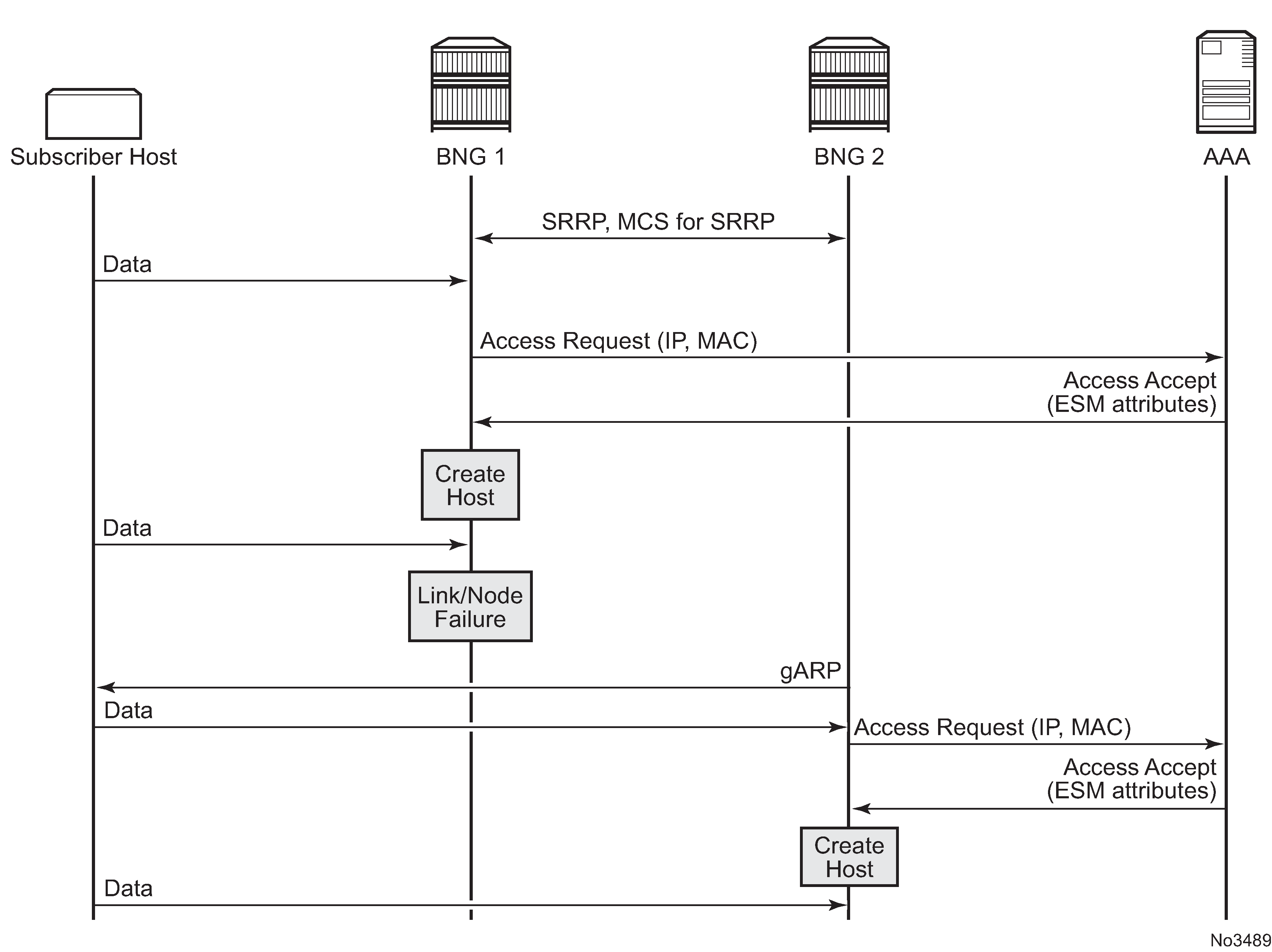
MSAP support
Stateless redundancy does not have information about MSAP because MCS is not used for synchronizing subscriber host information.
Static SAPs must be configured to rewrite FDBs on Layer 2 switches with G-ARP in access or aggregation networks.
Use the following CLI commands to rewrite FDBs with G-ARP.
group-interface <ip-int-name>
 sap <sap-id> create
 no shutdown
This requires the aggregation network to re-learn MAC for multiple C-VLANs using a single G-ARP from a specific C-VLAN.
Two typical scenarios are supported:
MSAP has qinq encap, and aggregation switches have per SVLAN FDB
MSAP has dot1q encap, and aggregation switches have per SVLAN FDB
(Aggregation switches push SVID)
IPv6 prefix learning
IPv6 prefix learning enables the creation of data-triggered IPv6 prefix-based hosts by learning prefixes from source IPv6 addresses of data-trigger packets where the prefix lengths are specified in LUDB or AAA.
IPv6 prefix learning is enabled with the following LUDB configuration conditions.
There are no ipv6-address, ipv6-delegated-prefix, or ipv6-slaac-prefix matching data-triggers in the LUDB host entry.
The ipv6-delegated-prefix-length is defined in the LUDB host entry.
IP prefix learning from AAA is enabled with the following conditions.
There are no Delegated-IPv6-Prefix, Framed-IPv6-Prefix, or Alc-IPv6-Address AVP-matching data-triggers in the Access-Accept or the AA-Answer responses.
Delegated-IPv6-Prefix AVP exists in the Access-Accept or the AA-Answer responses.
DHCP promotion is also supported on the data-triggered host created with IPv6 prefix learning.
RADIUS subscriber services
RADIUS subscriber services enable the activation and deactivation of subscriber functions by RADIUS Access-Accept or CoA messages. Each subscriber service can have its own RADIUS accounting session.
The subscriber service functionality is built using the flexible RADIUS Python script interface to populate the subscriber service data structure using a parameter list received in subscriber service-specific RADIUS Vendor Specific Attributes (VSAs). The format and content of the VSA parameter list is defined by the operator. An accounting start/stop is sent when the subscriber service is activated/deactivated. Optionally, interim updates can be sent in intervals that can be specified per subscriber service instance. Accounting interim updates and stop messages contain the subscriber service-related statistics (time or volume and time).
Subscriber services can be activated on a single-stack or dual-stack PPPoE or IPoE session or on a single-stack IPv4 host.
Subscriber service functionality can be built with:
QoS overrides: changing queue or policer parameters (PIR/CIR rates and CBS/MBS burst sizes), adapting rates of a parent scheduler, root arbiter, or subscriber aggregate rate
PCC rules: applying QoS or filter actions to a set of IP flows
Subscriber service building blocks
Subscriber services building blocks shows the building blocks required to activate or deactivate a subscriber service.

Each of the building blocks is described in the following sections.
RADIUS access-accept or CoA message with subscriber service activate or deactivate VSAs
A subscriber service instance is activated from the RADIUS server by an Access-Accept or CoA message for a PPPoE or IPoE session. Deactivation of a subscriber service instance can be achieved by a RADIUS CoA message or is implicit when the associated subscriber session terminates.
To activate a subscriber service, the Alc-Sub-Serv-Activate (VSA) is used, and to deactivate a subscriber service, the Alc-Sub-Serv-Deactivate VSA is used. The formats of the Alc-Sub-Serv-Activate and Alc-Sub-Serv-Deactivate VSAs can be freely defined by the operator if they match with the Python script that is used to commit the subscriber service instance activation or deactivation.
For example, to change the upstream and downstream bandwidth of an IPoE session, the following format can be defined:
rate-limit;<upstream_bw_in_kbps>;<downstream_bw_in_kbps>
To activate a subscriber service with an upstream bandwidth of 5 Mb/s and a downstream rate of 50 Mb/s, the following VSA can then be included in a RADIUS Access-Accept or CoA message:
Alc-Sub-Serv-Activate = "rate-limit;5120;30720"
To deactivate the same subscriber service and revert to the initial bandwidth, the following VSA can be included in a RADIUS CoA message:
Alc-Sub-Serv-Deactivate = "rate-limit;5120;30720"
To deactivate a subscriber service instance, its unique name must be used. In the example above, the name equals ‟rate-limit;5120;30720”.
To start an accounting session when the subscriber service instance is activated, the following attributes can be included in the Access-Accept or CoA message:
Alc-Sub-Serv-Acct-Stats-Type = volume-time | time
Alc-Sub-Serv-Acct-Interim-Ivl = <update-interval>
For example, the Alc-Sub-Serv-Acct-Stats-Type attribute value is set to ‟volume-time” to include both the session time for time-based billing and standard counters for volume statistics collection. The Alc-Sub-Serv-Acct-Interim-Ivl attribute sets the interval for interim updates of the subscriber service instance accounting.
See the Subscriber services RADIUS VSAs section for details on RADIUS attributes.
See the Subscriber service RADIUS accounting section for details on subscriber service instance accounting.
RADIUS Python interface
The SR OS RADIUS Python interface is used to interpret the parameters specified in the subscriber service-specific VSAs and to generate an internal proprietary format VSA representing the subscriber service instance to activate or deactivate, as shown in RADIUS Python interface.
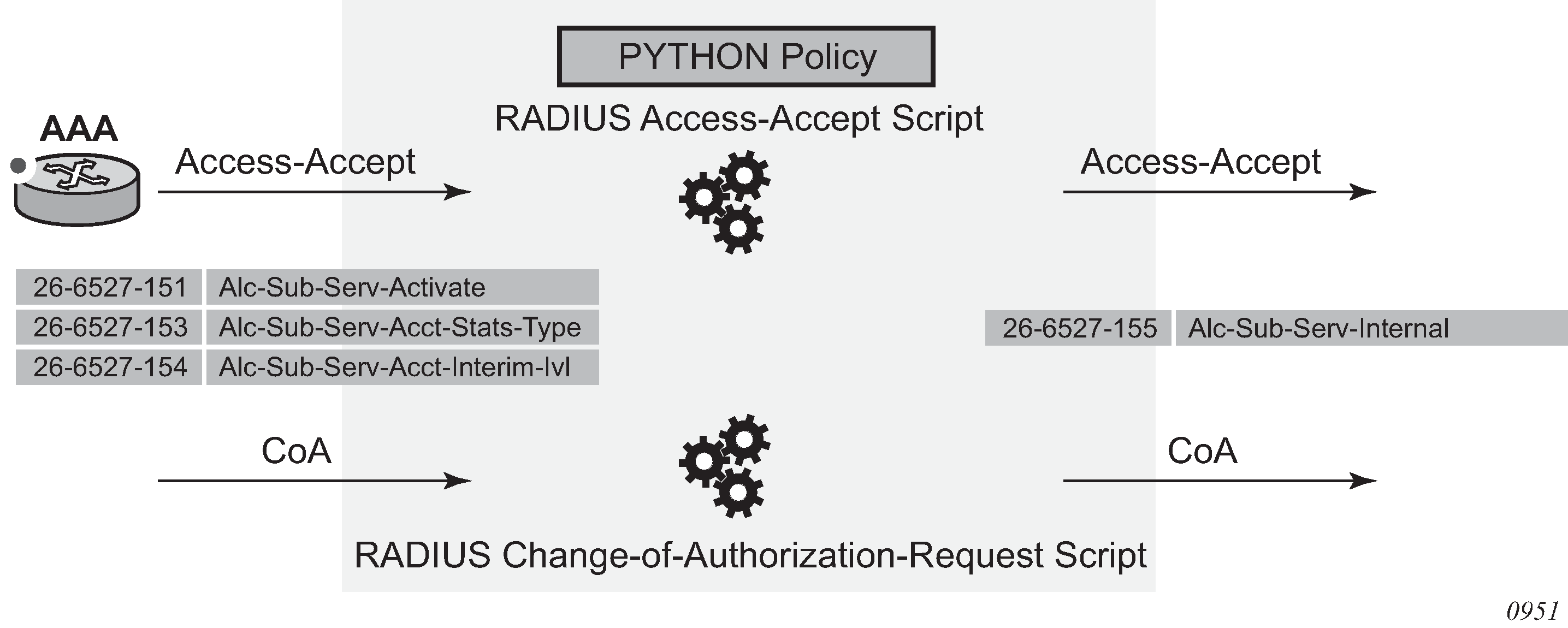
The SR OS only requires the Alc-Sub-Serv-Internal VSA [26-6527-155] to activate or deactivate the subscriber service. Subscriber service-specific VSAs [26-6527-151..154] are available to be used in the subscriber service Python script but are ignored in the SR OS.
See the Python script section for details on the subscriber services Python script functions and operation.
A Python script must be configured for RADIUS Access-Accept and CoA messages; for example:
config
    python
        python-script "subsvc-1" create
            primary-url "ftp://user:pwd@10.1.1.1/./py/subsvc-1.py"
            no shutdown
        exit
        python-policy "py-policy-subsvc-1" create
            radius access-accept direction ingress script "subsvc-1"
            radius change-of-authorization-request direction ingress script "subsvc-
1"
        exit
    exit
The Python policy must then be applied to the radius-server-policy to pass the Access-Accept messages to the Python script and to the RADIUS server to pass the CoA messages to the Python script. For example:
configure
    router
        radius-server
            server "server-1" address 10.1.1.2 secret <secret> create
                accept-coa
                python-policy "py-policy-subsvc-1"
            exit
        exit
    exit
    aaa
        radius-server-policy "aaa-server-policy-1" create
            python-policy "py-policy-subsvc-1"
            servers
                access-algorithm round-robin
                router "Base"
                server 1 name "server-1"
            exit
        exit
    exit
Python script
The RADIUS Access-Accept and CoA messages are passed to the configured RADIUS Python scripts. As shown in Subscriber service Python script operation, the function of the subscriber service Python script is to interpret the subscriber service-specific VSAs that contain the subscriber service instance parameters and to generate a new Alc-Sub-Serv-Internal VSA containing the information required to activate the actual subscriber service on the PPPoE or IPoE session.
This section covers the basics to understand the functionality of a subscriber service Python script. See the Subscriber services Python API section for a detailed description of the alc.sub_svc Python module containing functions and data structures used to define and activate a subscriber service instance.
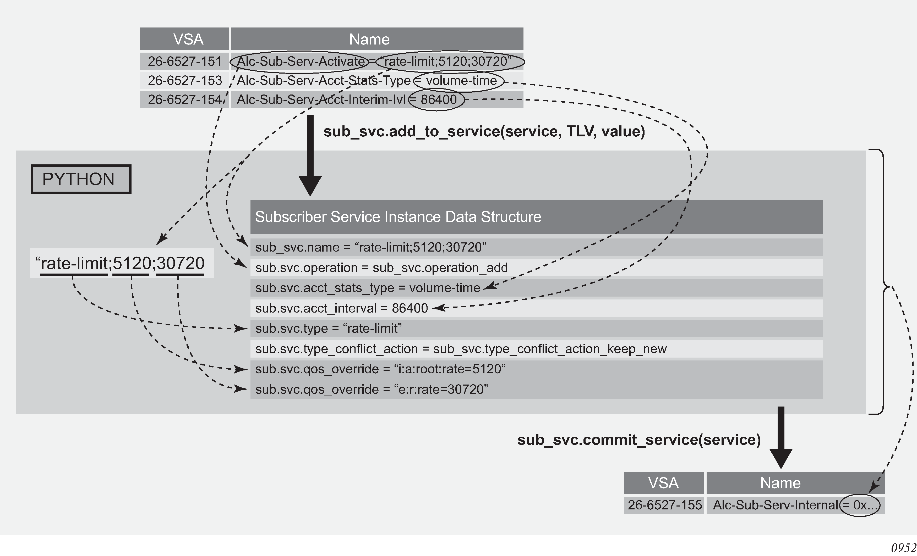
The alc.sub_svc Python module contains the required functions and data structure to commit a subscriber service, including:
TLVs to build a data structure describing the subscriber service functionality, such as QoS overrides or PCC rules
functions to populate the data structure such as sub_svc.add_to_service(), sub_svc.pccrule.add_to_pccrule(), and sub_svc.flow.add_to_flow()
a function to commit the subscriber service and create the internal VSA from the data structure: sub_svc.commit_service()
Python script example
In this section an example of a Python script is described that enables the activation or deactivation of a subscriber service.
In the example, it is assumed that only a single subscriber service is activated or deactivated per RADIUS message (no tagged VSAs are used) and that only a single Alc-Sub-Serv-Activate or Alc-Sub-Serv-Deactivate VSA is present (no concatenation of VSAs is required).
To change the upstream root arbiter rate and downstream aggregate rate bandwidth of an IPoE session, send the following parameters in the subscriber service activate VSA:
rate-limit;<upstream_bw_in_kbps>;<downstream_bw_in_kbps>
During the bandwidth change, the traffic should be accounted for in a separate accounting session.
To import the required modules in the Python script:
# Python - imports
import struct
from alc import radius
from alc import sub_svc
The alc.radius module provides the API access to the RADIUS VSAs in Access-Accept and CoA messages.
The alc.sub_svc module allows the API to activate and deactivate subscriber services.
The struct module is a Python module used in the example to convert data obtained from the RADIUS API as a string into Python integer values.
The following constants are used in the script:
# Python - constants
# VSA vendor ID
ALC = 6527
# ALC Radius VSA
SUB_SERVICE_ACTIVATE = 151
SUB_SERVICE_DEACTIVATE = 152
SUB_SERVICE_ACCT_STATS_TYPE = 153
SUB_SERVICE_ACCT_INTERIM_IVL = 154
The main flow in a subscriber service Python script is to first process the subscriber service deactivations, followed by the subscriber service activations. Optionally, the subscriber service-specific VSAs can be removed from the RADIUS message as they are not required for further processing in the SR OS:
# Python - main()
deactivate_services()
activate_services()
radius.attributes.clearVSA(ALC, SUB_SERVICE_ACTIVATE)
radius.attributes.clearVSA(ALC, SUB_SERVICE_DEACTIVATE)
radius.attributes.clearVSA(ALC, SUB_SERVICE_ACCT_STATS_TYPE)
radius.attributes.clearVSA(ALC, SUB_SERVICE_ACCT_INTERIM_IVL)
The function to deactivate a subscriber service executes the following steps:
checks if an Alc-Sub-Serv-Deactivate VSA [26-6527-152] is present
if present:
builds the subscriber service data structure. For a subscriber service deactivation, only the subscriber service instance name is required.
commits the subscriber service deactivation
# Python - deactivate_services()
def deactivate_services():
  value = radius.attributes.getVSA(ALC, SUB_SERVICE_DEACTIVATE)
  if value != '':
    service = []
    sub_svc.add_to_service(service, sub_svc.name, value);
    sub_svc.add_to_service(service, sub_svc.operation, sub_svc.operation_del);
    sub_svc.commit_service(service)
The function to activate a subscriber service executes the following steps:
checks if an Alc-Sub-Serv-Activate VSA [26-6527-151] is present
if present:
separates the parameters in the attribute value with a semicolon as the delimiter. The parameters are the subscriber service type, the upstream bandwidth in kb/s, and the downstream bandwidth in kb/s.
If the subscriber service type is rate-limit, builds the subscriber service data structure:
specifies that the service is added (activate)
adds the complete attribute value as the subscriber service instance name. This name should also be used to deactivate the subscriber service.
sets the subscriber service type and conflict action. With the conflict action set to ‟keep new”, if a new subscriber service of the same type is activated, the old one is deactivated first.
configures the upstream and downstream bandwidth with a QoS override on the ingress root arbiter and egress aggregate rate
If the subscriber service type is something else (an unknown service type), a warning is printed for debugging purposes. No action is performed in this case.
If an Alc-Sub-Serv-Acct-Stats-Type VSA [26-6527-153] is present, adds the corresponding stats-type to the subscriber service data structure. The function also checks whether a Alc-Sub-Acct-Serv-Interim-Ivl VSA [26-6527-154] is present and adds the interval to the subscriber service data structure.
Both the stats-type and interim interval must be specified as integers in the subscriber service data structure. As the RADIUS API returns an octet string, a conversion is required. The struct.unpack() function is used for this purpose.
commits the subscriber service activation
# Python - activate_services()
def activate_services():
  # Subscriber Service Activate VSA
  value = radius.attributes.getVSA(ALC, SUB_SERVICE_ACTIVATE)
  if value != '':
    values = value.split(';')
    if values[0] == "rate-limit":
      service = []
      sub_svc.add_to_service(service, sub_svc.operation, sub_svc.operation_add);
      sub_svc.add_to_service(service, sub_svc.name, value);
      sub_svc.add_to_service(service, sub_svc.type, 'rate-limit')
      sub_svc.add_to_service(service, sub_svc.type_conflict_action, sub_svc.type_con
flict_action_keep_new)
      sub_svc.add_to_service(service, sub_svc.qos_override, 'i:a:root:rate=' +
values[1])
      sub_svc.add_to_service(service, sub_svc.qos_override, 'e:r:rate=' + values[2])
    else:
      print "WARNING - Unknown service type :", values[0]
      return
    # Subscriber Service Accounting VSA
    stats_type = radius.attributes.getVSA(ALC, SUB_SERVICE_ACCT_STATS_TYPE)
    if stats_type != '':
      sub_svc.add_to_service(service, sub_svc.acct_stats_type, struct.unpack("!I", s
tats_type)[0]);
      interval = radius.attributes.getVSA(ALC, SUB_SERVICE_ACCT_INTERIM_IVL)
      if interval != '':
        sub_svc.add_to_service(service, sub_svc.acct_interval, struct.unpack("!I", i
nterval)[0]);
    # Activate the Subscriber Service
    sub_svc.commit_service(service)
The result of the sub_svc.commit_service() function is an Alc-Sub-Serv-Internal VSA [26-6527-155] that contains the required data for the SR OS to activate the corresponding subscriber services.
Subscriber service instance activation or deactivation with optional RADIUS accounting
When the SR OS receives an Alc-Sub-Serv-Internal VSA [26-6527-155] in an Access-Accept or CoA message as a result of the Python script sub_svc.commit_service() function, the corresponding subscriber services are activated or deactivated. Optionally, an accounting session can be started for each subscriber service instance.
The following is an example of the show service sub-services command.
# show service sub-services
===============================================================================
Subscriber service table
===============================================================================
Username        : cpe2@domain1.com
Subscriber      : cpe2@domain1.com                     Type     : PPP
SAP             : 1/1/4:1201.5                         Service  : 1000
MAC Address     : 00:51:00:00:01:01                    PPPoE-SID: 114
IP              : 10.1.1.3
Interface-ID    : 02:51:00:FF:FE:00:01:01
-------------------------------------------------------------------------------
  Service instance : rate-limit;5120;30720
  up time          : 0d 00:01:06
  type             : rate-limit
  acct sess id     : 144DFF00000A2556B757DA
  multi sess id    : 144DFF00000A1156B71E44
  acct type        : volume-time
  acct ivl         : 1d 00:00:00
  input octets     : 0
  input packets    : 0
  output octets    : 0
  output packets   : 0
  actions          :
  QoS-override
    ingress arbiter "root" rate 5120
  QoS-override
    egress aggregate rate limit 30720
-------------------------------------------------------------------------------
number of subscriber services found: 1
===============================================================================
The following rules apply for a subscriber service instance.
A subscriber service instance can be activated on a:
single-stack or dual-stack PPPoE session
single-stack or dual-stack IPoE session
single-stack IPoEv4 host
A subscriber service instance is uniquely identified by its name. To deactivate a subscriber service instance, the subscriber service name must be referenced.
A subscriber service cannot be modified. To update a subscriber service instance, the old subscriber service must be deactivated and a new one activated.
Multiple subscriber services can be activated or deactivated in a single Access-Accept or CoA message. Tagged subscriber service-specific VSAs are available for this purpose.
A single subscriber service instance can have multiple actions, such as multiple QoS overrides or multiple PCC rules.
The conflict action determines the behavior when multiple subscriber services of the same type are activated for the same PPPoE or IPoE session:
Conflict action = none
Multiple instances of the same type can be activated.
Conflict action = keep new
Only a single subscriber service instance of the same type is allowed.
When a new subscriber service instance of the same type is activated on a single PPPoE or IPoE session, the old instance is deactivated, and the new subscriber service instance is activated.
Conflict action = keep old
Only a single subscriber service instance of the same type is allowed.
When a subscriber service instance of the same type is activated on a single PPPoE or IPoE session, the new subscriber service instance is rejected.
Multi-Chassis Synchronization (MCS) is not supported for subscriber services.
Subscriber services RADIUS VSAs
Subscriber services VSAs 26-6527-151..154 are used as inputs for the subscriber service Python script and are ignored by the SR OS.
The subscriber service VSAs can be tagged to allow activation and deactivation of multiple subscriber service instances with a single RADIUS Access-Accept or CoA message.
Subscriber services RADIUS VSAs lists the subscriber services RADIUS VSAs. See the RADIUS Attributes Reference Guide for a complete description of the subscriber services VSAs.
| Attribute ID | Attribute name | Description |
|---|---|---|
26-6527-151 |
Alc-Sub-Serv-Activate (string) |
Activate a subscriber service. The attribute contains parameters as input for the subscriber service Python script to define and activate a subscriber service. Multiple VSAs can be included per message if the parameter list does not fit in a single attribute. |
26-6527-152 |
Alc-Sub-Serv-Deactivate (string) |
Deactivate a subscriber service. The attribute contains parameters as input for the subscriber service Python script to deactivate a subscriber service. Multiple VSAs can be included per message if the parameter list does not fit in a single attribute. |
26-6527-153 |
Alc-Sub-Serv-Acct-Stats-Type (integer) |
Enable or disable subscriber service accounting and specify the statistics type: volume and time or time only. Values: 1=off, 2=volume-time and 3=time |
26-6527-154 |
Alc-Sub-Serv-Acct-Interim-Ivl (integer) |
The interim accounting interval in seconds at which Acct-Interim-Update messages should be generated for subscriber service accounting. A value of 0 (zero) corresponds to no interim update messages. The maximum value is 300 seconds (values 1 to 300). |
26-6527-155 |
Alc-Sub-Serv-Internal |
For internal use only. Its value is the result of the subscriber service commit function in Python. (sub_svc.commit_service). |
Subscriber service RADIUS accounting
The configuration for subscriber service instance accounting sessions is obtained from the RADIUS accounting policies configured in the subscriber profile of the parent subscriber:
The accounting destinations: RADIUS server configuration
Subscriber service instance accounting is sent to multiple destinations when multiple RADIUS accounting policies are configured (for example, config>subscr-mgmt>sub-prof# radius-accounting policy acct-policy-1 acct-policy-2)
Up to five accounting policies can be configured. Each policy is independent of the other, with its own accounting mode, update interval, and include attributes. Because resources are limited for sending out RADIUS account messages, contact your Nokia technical support representative for recommendations.
The accounting attributes (include-radius-attribute) with some exceptions.
Standard accounting attributes are always used for volume accounting, regardless of the configuration in the RADIUS accounting policy.
An untagged [26-6527-151] Alc-Sub-Serv-Activate attribute is included in all subscriber service instance accounting messages. Its value is the subscriber service instance name (alc.sub_svc.name).
Accounting interim updates for subscriber service instance accounting are controlled independently from the parent subscriber accounting session:
Enabling accounting interim updates for a subscriber service instance is achieved by setting the sub_svc.acct_interval TLV in the subscriber services Python script to a value greater than 0: sub_svc.add_to_service(service, sub_svc.acct_interval, 3600)
Disabling accounting interim updates for a subscriber service instance is achieved by setting the sub_svc.acct_interval TLV in the subscriber services Python script to 0: sub_svc.add_to_service(service, sub_svc.acct_interval, 0)
If the parent subscriber has no RADIUS accounting policy configured, subscriber service instance accounting cannot be enabled.
If the parent subscriber has a RADIUS accounting policy configured, subscriber service instance accounting can be disabled by setting the sub_svc.acct_stats_type TLV in the subscriber service Python script to 1 (Off):
sub_svc.add_to_service(service, sub_svc.acct_stats_type, 1)
Each subscriber service instance has a unique accounting session ID included as [44] Acct-Session-Id. The [50] Acct-Multi-Session-Id contains the accounting session ID of the parent PPPoE or IPoE session as shown in Subscriber service accounting multi-session ID.
| Subscriber service parent | [50] Acct-Multi-Session-Id |
|---|---|
PPPoE session |
Session Acct-Session-Id of the PPPoE session: show service id <service-id> pppoe session detail |
IPoE session |
Session Acct-Session-Id of the IPoE session: show service id <service-id> ipoe session detail |
IPoEv4 host |
Host Acct-Session-Id of the IPoEv4 host: show service id <service-id> subscriber-hosts detail |
The content of the volume counters when the subscriber service accounting statistics type equals volume-time is determined by the subscriber service action. For details, see the subscriber service sections that follow.
Accounting-only subscriber service
An accounting-only subscriber service has no specific action such as qos-override or pccrule defined and has subscriber service instance accounting enabled.
An example of when an accounting-only subscriber service would be used is if additional accounting data is needed for a specific time period in the lifetime of a PPPoE or IPoE session.
The sub_svc.acct_stats_type TLV in the subscriber services Python script must be set to a value different from 1 (Off) to enable subscriber service instance accounting. For example:
# Python example - Accounting only subscriber service
service = []
sub_svc.add_to_service(service, sub_svc.operation, sub_svc.operation_add)
sub_svc.add_to_service(service, sub_svc.name, 'subsvc-acct-1')
sub_svc.add_to_service(service, sub_svc.type, 'acct-only')
sub_svc.add_to_service(service, sub_svc.type_conflict_action, sub_svc.type_conflict_
action_none)
sub_svc.add_to_service(service, sub_svc.acct_stats_type, 2)
sub_svc.add_to_service(service, sub_svc.acct_interval, 3600)
sub_svc.commit_service(service)
The volume counters for subscriber service statistics type volume-time contain the aggregate forwarded octets and packets of the parent PPPoE or IPoE session sla-profile instance from the start of the subscriber service.
QoS override-based subscriber service
A subscriber service instance with a qos-override action overrides queue or policer parameters (CIR, PIR, CBS, MBS) configured at the sla-profile level and hierarchical QoS parameters (aggregate rate, scheduler rate, or root and intermediate arbiter rate) configured at the sub-profile level.
An example of when a QoS override-based subscriber service would be used is to temporarily offer higher bandwidth and charge for the volume consumed during this period. Sample use case: QoS override-based subscriber services shows the volume statistics that are reported for the PPPoE or IPoE session accounting and for each of the subscriber service instances accounting sessions that were activated and deactivated.
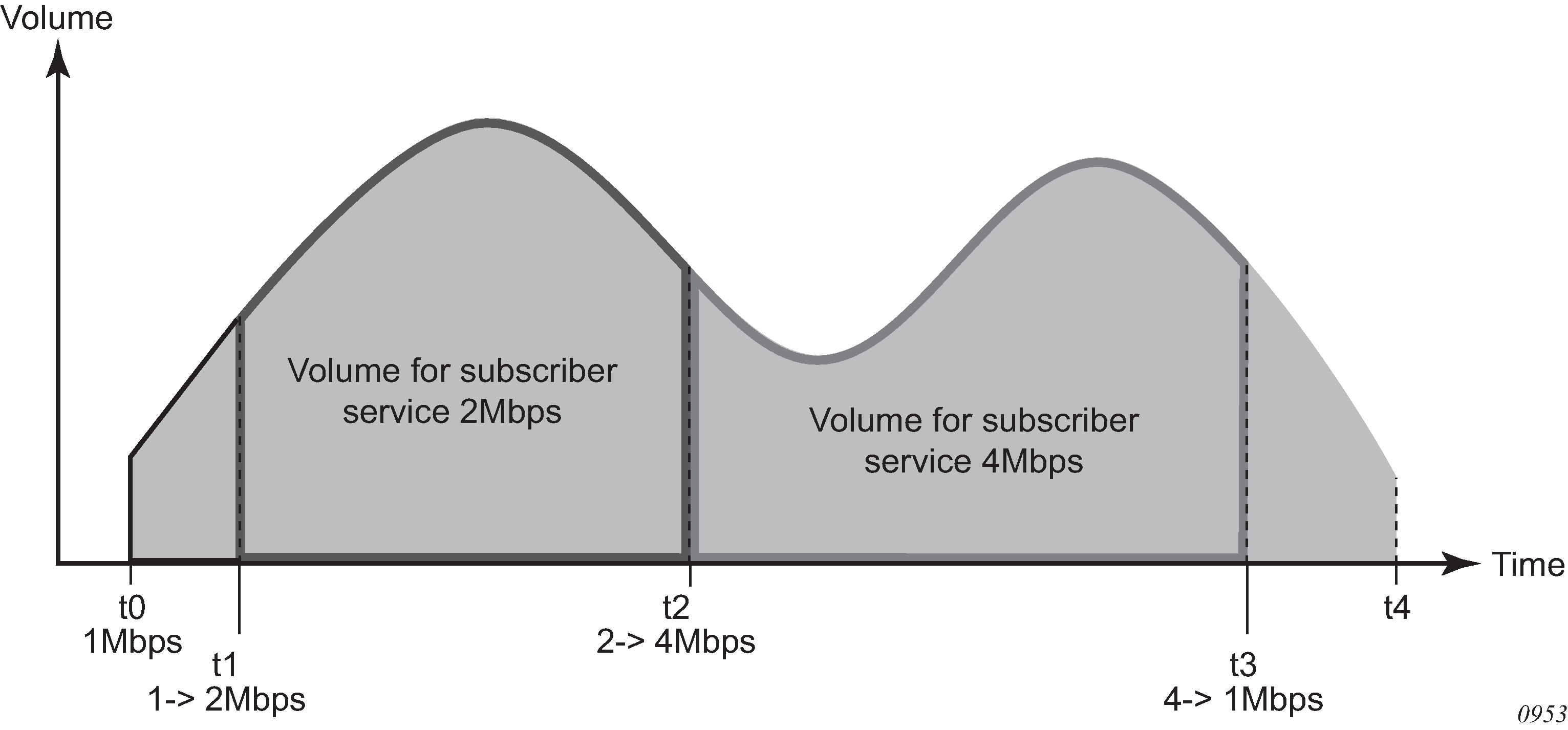
At t0, a subscriber connects and starts consuming bandwidth at the subscriber base egress rate of 1 Mb/s. An accounting session is started for the subscriber.
At t1, a QoS override-based subscriber service instance is activated that boosts the download bandwidth to 2 Mb/s. A 2 Mb/s QoS override-based subscriber service instance accounting session is started.
At t2, the 2 Mb/s QoS override-based subscriber service instance is deactivated and replaced with a new one that increases the download bandwidth to 4 Mb/s. The 2 Mb/s QoS override-based subscriber service accounting session is terminated, reporting the volume consumed during t1 to t2. A new 4 Mb/s QoS override-based subscriber service accounting session is started.
At t3, the 4 Mb/s QoS override-based subscriber service instance is deactivated. The download bandwidth is reduced to the 1 Mb/s base rate again. The 4 Mb/s QoS override-based subscriber service accounting session is terminated, reporting the volume consumed during t2 to t3.
At t4, the subscriber disconnects. The accounting session for the subscriber is terminated, reporting the volume consumed during t0 to t4.
The sub_svc.qos_override TLV in the subscriber services Python script adds a qos-override action. For example:
# Python example - QoS override subscriber service
service = []
sub_svc.add_to_service(service, sub_svc.operation, sub_svc.operation_add)
sub_svc.add_to_service(service, sub_svc.name, 'subsvc-qos-override-1')
sub_svc.add_to_service(service, sub_svc.type, 'qos-override')
sub_svc.add_to_service(service, sub_svc.type_conflict_action, sub_svc.type_conflict_
action_keep_new)
sub_svc.add_to_service(service, sub_svc.qos_override, 'e:q:1:pir=20000,cir=0')
sub_svc.add_to_service(service, sub_svc.qos_override, 'e:q:2:pir=5000,cir=5000')
sub_svc.add_to_service(service, sub_svc.qos_override, 'i:p:1:pir=1000,cir=0')
sub_svc.add_to_service(service, sub_svc.qos_override, 'e:r:rate=20000')
sub_svc.commit_service(service)
Actual values are used to populate the subscriber service data structure in this example; typically, these values are sent as parameters in subscriber service-specific VSAs.
Although a QoS override-based subscriber service instance is activated for a PPPoE or IPoE session, the overrides are applied at the SLA profile instance and subscriber level.
QoS override-based subscriber services have precedence over dynamic QoS overrides (RADIUS Alc-Subscriber-QoS-Override VSA or Gx Charging-Rule-Definition with QoS-Information) on the PPPoE or IPoE session.
When a dynamic QoS override such as by the Alc-Subscriber-QoS-Override VSA is active on the parent PPPoE or IPoE session and a QoS override-based subscriber service is activated, the action from the QoS override-based subscriber service is installed. When the QoS override-based subscriber service is later deactivated, the original dynamic QoS override is restored.
When a dynamic QoS override such as by the Alc-Subscriber-QoS-Override VSA is received for a parent PPPoE or IPoE session with an active QoS override-based subscriber service, the QoS override-based subscriber service remains installed. If the QoS override-based subscriber service is later deactivated, the previously received dynamic QoS override is installed.
When both a QoS override-based subscriber service activation and a dynamic QoS override such as by the Alc-Subscriber-QoS-Override VSA is received in a single message for the parent PPPoE or IPoE session, the QoS override-based subscriber service action is installed and the dynamic QoS override is stored for later reference. When the QoS subscriber service is later deactivated, the previously received dynamic QoS override is installed.
The installed QoS override actions can be verified in the output of the show service active-subscribers detail CLI command.
The volume counters for subscriber service statistics type volume-time contain the aggregate forwarded octets and packets of the parent PPPoE or IPoE session sla-profile instance because of the start of the subscriber service.
QoS override-based subscriber services are stored in the subscriber-mgmt persistency file.
PCC rule-based subscriber services
Policy and Charging Control (PCC) rules are defined in the 3GPP PCC architecture and used in the Diameter Gx application as a collection of parameters that enable IP traffic flows to be identified, QoS parameters and filtering actions to be applied to these flows, and charging to be performed on them. The use of PCC rules in policy management by the Diameter Gx interface is described in the PCC Rules.
The same PCC rule construct is used in RADIUS subscriber services to enable IP flow-based actions and accounting.
Identify IP flows based on 5-tuple (protocol, source and destination IP address, source and destination port) and DSCP value.
Apply QoS actions to these flows, such as rate limiting or change of forwarding class.
Apply filter actions to these flows, such as forward, drop, HTTP redirect, redirect to a next hop or routing instance.
Enable RADIUS accounting to report the forwarded octets and packets of the IP flows.
IP flow-based accounting can be used for a subscriber service using PCC rules. Activated by a self-service portal or as part of an Internet subscription package, applications identified by a 5-tuple receive specific treatment, such as bandwidth increase, expedited forwarding, or zero rating. Volume and time statistics for the application data is available in the subscriber service RADIUS accounting session. This is shown in Example: PCC rule-based subscriber service.
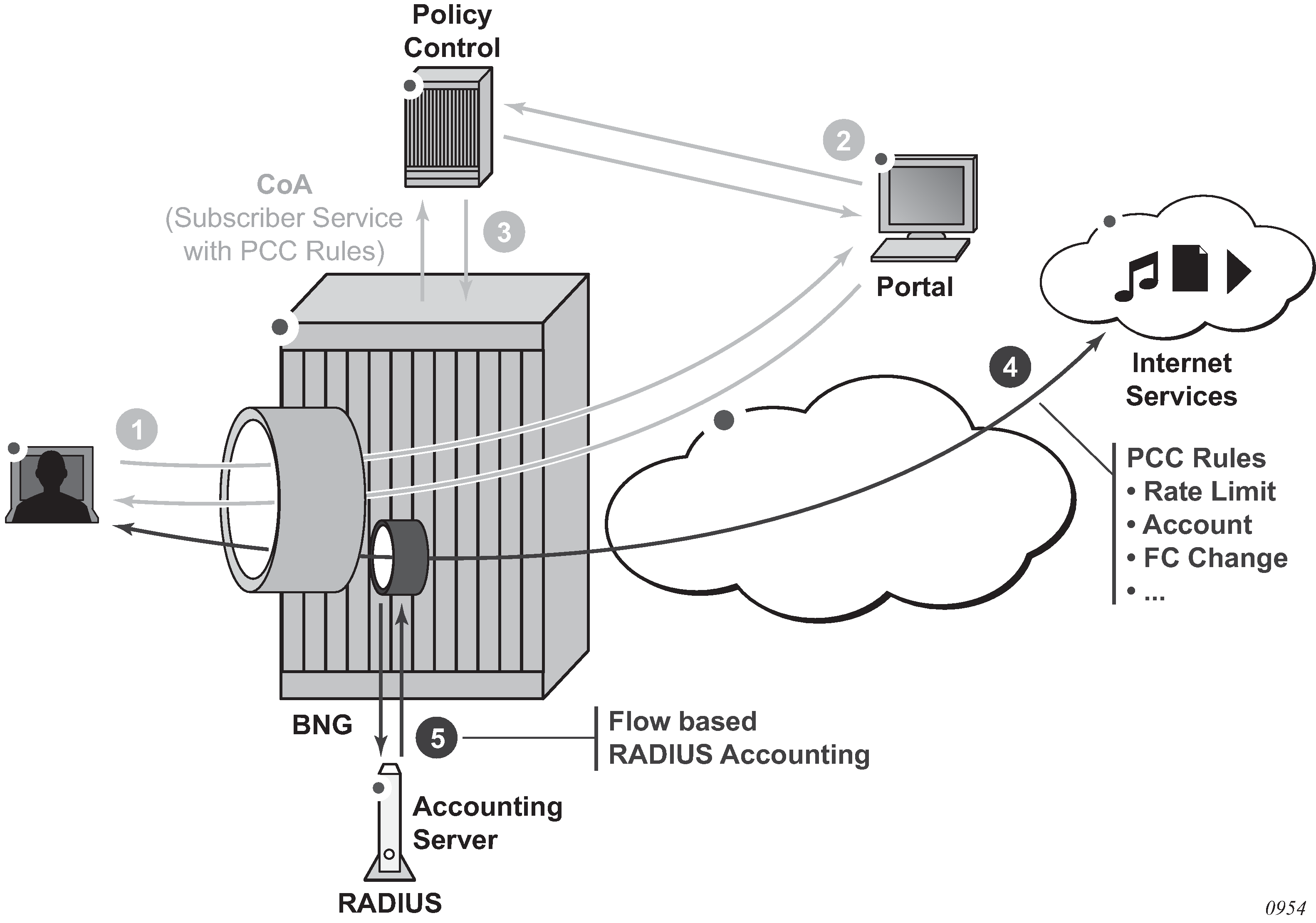
The user subscribes to a service by a web portal.
The policy control is informed of the new subscription.
The policy control instructs the BNG by RADIUS to activate a subscriber service with PCC rules.
The subscriber service is instantiated on the BNG. A dynamic policer is spawned to optionally rate-limit or count the application traffic.
The subscriber service instance accounting session reports the volume of traffic forwarded as part of this service.
PCC rule actions
A PCC rule is a unidirectional set of IP flows sharing a same set of actions. IPv4 and IPv6 flows can be combined within the same PCC rule.
A PCC rule name must be unique for each rule applied on a single PPPoE or IPoE session. For optimal PCC rule sharing, it is recommended that the same PCC rule name be used when its content is the same (that is, the same set of flows and same set of actions).
An IP flow is identified by a combination of:
5-tuple (IPv4 or IPv6): src-ip, src-port, dst-ip, dst-ip, protocol, next-header
DSCP value
The CLI equivalent is:
 match protocol | next-header <protocol>
        src-ip <ip-address>
        dst-ip <ip-address>
        src-port eq <port> | range <start-port> <end-port>
        dst-port eq <port> | range <start-port> <end-port>
        dscp <dscp>
    exit
Supported actions include forward, drop, redirect to ip next hop, redirect to a routing instance, HTTP redirect, forwarding class change, rate-limit, and account.
With a specified set of actions, PCC rules are instantiated in the SR OS by IP criteria or IPv6 criteria entries in SAP ingress or SAP egress QoS polices and in IP or IPv6 filter entries. A PCC rule precedence value determines the relative order of different PCC rules when inserted in the QoS or filter policy: a rule with a lower precedence value is be applied before a rule with a higher precedence value. Rules with the same precedence can be automatically optimized; the relative order in which they are applied is determined by the system for optimal sharing. Rules with no precedence are applied at the end and are also automatically optimized.
Subscriber service PCC rule actions resulting in QoS policy changes and Subscriber service PCC rule actions resulting in filter changes provide an overview of the PCC rule actions and where they apply.
| Action | Direction | Description |
|---|---|---|
Forwarding Class (FC) change |
Ingress/Egress |
changes the QoS forwarding class CLI equivalent: |
Rate-limit (PIR/CIR) |
Ingress/Egress |
rate-limit traffic matching the specified flows
The forwarded octets and packets statistics of the dynamic policer are included in subscriber service accounting. CLI equivalent: |
Account |
Ingress / Egress |
counts traffic matching the specified flows:
The forwarded octets and packets statistics of the dynamic policer are included in subscriber service accounting. CLI equivalent: |
Forward |
Ingress/Egress |
Creates an entry in the QoS policy to forward the traffic without explicit QoS action. Matching traffic does not match on the next entry (match and exit behavior). In case of overlapping flows, such as account all traffic except flow 1 and flow 2, the more specific flows must be explicitly forwarded. CLI equivalent: |
| Action | Direction | Description |
|---|---|---|
Forward/Drop |
Ingress/Egress |
Creates a filter entry to forward or drop the traffic CLI equivalent: |
Redirect to an IP next-hop |
Ingress |
redirect the traffic to the specified IP next-hop CLI equivalent: |
Redirect to a routing instance |
Ingress |
redirect the traffic to the specified routing instance CLI equivalent: |
HTTP redirect |
Ingress |
HTTP redirection to the specified URL CLI equivalent: |
Supported combinations of ingress PCC rule actions and Supported combinations of egress PCC rule actions show the actions that can be combined in a single ingress or egress PCC rule.
Consider the following rules:
-
The Flow Status can only be set by Gx.
For RADIUS subscriber service-based PCC rules, the Flow Status is fixed to Enabled.
-
The filter action forward is ignored (not installed) when combined with the following filter actions: redirect next-hop, redirect router, or http-redirect.
-
The QoS action forward is ignored (not installed) when combined with the following QoS actions: rate-limit, FC change, account/Usage Monitoring (UM).
-
When the QoS action rate-limit and QoS action account or Usage Monitoring (UM) are combined, only a single dynamic policer is installed, which is used for both rate-limiting and obtaining forward statistics for accounting or usage monitoring.
PCC rule instantiation
A PCC rule can result in one or more IPv4/IPv6 filter and QoS policy IPv4/IPv6 criteria entries. This is transparent to the operator.
A PCC rule is split into IPv4 filter entries, IPv6 filter entries, SAP ingress QoS IP or IPv6 criteria, and SAP egress QoS IP or IPv6 criteria.
Each entry is inserted into the corresponding policy at a reserved range for dynamic PCC rule inserts. Within the reserved range, the (optional) precedence value for the rule is considered for the relative order of different PCC rules.
The QoS rate-limit and account actions spawn a dynamic policer from a reserved range in the QoS policy. A template configuration provides dynamic policer parameters such as hierarchical policer parent, burst sizes (MBS, CBS), statistics mode and packet byte offset. Each of the dynamic policer parameters configured in the template can be overridden per PCC rule in the subscriber service activation (see PCC Rule TLVs in the alc.sub_svc.pccrule module ). A maximum of one dynamic policer is instantiated per PCC rule. There is a maximum of 63 dynamic policers per direction and per SLA profile instance. The output queue for PCC rule traffic mapped in the dynamic policer is determined by a mechanism called forwarding class inheritance: the output queue is the same queue that would be used if a packet with the same forwarding class as the PCC rule packet was classified using the applied QoS policy. The resulting output queue can be a local subscriber queue (when the FC is mapped to a queue or when the FC is mapped to a policer at egress and the policer is mapped to a local queue), a shared queue (when the FC is mapped to a policer at ingress) or a queue-group queue (when the FC is mapped to a policer at egress).
Optimal policy and rule sharing is achieved by QoS and filter policy cloning and internal PCC rule optimizations. The mechanisms are the same as for Gx-initiated PCC rules as described the Generic Policy Sharing and Rule Sharing and Gx Rule Ordering.
PCC rule sharing can only happen when the content is the same: identical name, direction, precedence value, set of flows, and set of actions. PCC rules with the same content have the same PCC rule ID.
Filter and QoS policy clones that result from PCC rule instantiation can be recognized by a filter ID or QoS policy ID in the format 1 to 65535:P1 to 4096; for example, filter ip 10:p3
PCC rules can be inactive if the corresponding host type is not present. For example, a PCC rule-based subscriber service with an IPv6 filter action can be activated on an IPoE session while there is no IPv6 host instantiated on the session. When the IPv6 host is later created, the PCC rule is activated.
The following initial configuration is required before activating PCC rule-based subscriber services.
To install PCC rule QoS actions, a non-default ingress and egress QoS policy with a sub-insert-shared-pccrule range configured must be associated with the IPoE or PPPoE session (the default QoS policy cannot be modified). If a rate-limit or account action is needed, a dynamic policer range must also be configured. Additional dynamic policer parameters are optional and can be overridden per PCC rule in the subscriber service activation (see PCC Rule TLVs in the alc.sub_svc.pccrule module ).
configure qos
    sap-ingress <policy-id> create
        sub-insert-shared-pccrule start-entry <entry-id> count <count>
        dynamic-policer
            range start-entry <policer-id> count <count>
            packet-byte-offset {add <add-bytes> | subtract <sub-bytes>}
            mbs <size> [bytes|kilobytes]
            cbs <size> [bytes|kilobytes]
            parent <arbiter-name> [weight <weight-level>] [level <level>]
            stat-mode <stat-mode>
        exit
    exit
To install PCC rule filter actions, an IPv4 or IPv6 filter with sub-insert-shared-pccrule range configured must be associated with the IPoE or PPPoE session.
Although a PCC rule-based subscriber service is activated on a PPPoE or IPoE session, the actions are applied at the SLA profile instance and subscriber host level.
PCC rule QoS actions result in QoS policy clones that are applied at the SLA profile instance level. Traffic from all subscriber hosts and sessions sharing the SLA profile instance is subject to the specified actions.
PCC rule filter actions result in IPv4 or IPv6 filter clones that are applied at the subscriber host level. Only traffic from the subscriber host of the same type (IPv4 or IPv6) that belongs to the PPPoE or IPoE session is subject to the specified actions.
A PCC rule with flow match criteria that are not explicitly IPv4 or IPv6 results in both IPv4 and IPv6 match criteria being installed; for example, destination address = any.
Filter actions are executed before QoS actions. If an IP flow is rate-limited, it should pass the IPv4 or IPv6 filter first. Adding a QoS action rate limit to a PCC rule does not automatically insert a corresponding forward entry in an IP filter. When needed, this must be done explicitly by the operator with a filter forward action. For example, an IP filter with the default action drop and several explicit forward entries is applied to an IPoE session. A new IP flow must be rate-limited and accounted for. The PCC rule should include match criteria for the IP flow and a QoS action rate limit, QoS action account, and filter action forward. Without the filter action forward, the IP flow would be dropped by the default action in the filter policy.
config>filter
    ip-filter <filter-id> create
        sub-insert-shared-pccrule start-entry <entry-id> count <count>
    exit
    ipv6-filter <filter-id> create
        sub-insert-shared-pccrule start-entry <entry-id> count <count>
    exit
See Bulk Changes while Gx Rules are Active for information about the parameters that can be changed in the base filter and QoS policies when PCC rules are applied.
PCC rules in a subscriber service
The example below shows a pseudo-language representation of PCC rules in a subscriber service.
A subscriber service can contain multiple PCC rules. Because a PCC rule is unidirectional, including an ingress and an egress PCC rule enables subscriber service accounting of bidirectional flows.
A PCC rule can contain multiple flows. Flows in a PCC rule can be a mix of IPv4 and IPv6 flows.
Per PCC rule dynamic policer parameters can optionally be specified. These parameters override the dynamic-policer configuration in the sap-ingress or sap-egress QoS policies.
subscriber-service {
    name = <subsvc name>
    operation = add | delete
    acct-stats-type = off | volume-time | time
    acct-interval = <value>
    type = <string>
    type-conflict-action = keep-old | keep-new | none
    pcc-rule {
        name = <name>
        direction = ingress | egress
        flow = <5-tuple> | <dscp>
        flow = <5-tuple> | <dscp>
           …
        flow = <5-tuple> | <dscp>
        action = <action>
        action = <action>
           …
        action = <action>
        precedence = <value>
        policer {
            parent-arbiter = <arbiter-name>
            parent-level = <level>
            parent-weight = <weight-level>
            mbs = <bytes | default>
            cbs = <bytes | default>
            stat-mode = <stat-mode>
            packet-byte-offset = <offset>
        }
    }
    …
    pcc-rule {
        name = <name>
        direction = ingress | egress
        flow = <5-tuple> | <dscp>
        flow = <5-tuple> | <dscp>
           …
        flow = <5-tuple> | <dscp>
        action = <action>
        action = <action>
           …
        action = <action>
        precedence = <value>
        policer {
            parent-arbiter = <arbiter-name>
            parent-level = <level>
            parent-weight = <weight-level>
            mbs = <bytes | default>
            cbs = <bytes | default>
            stat-mode = <stat-mode>
            packet-byte-offset = <offset>
        }
    }
}
The sub_svc.pccrule TLV in the subscriber services Python script adds a PCC rule to the subscriber service, as shown in the output example below:
Actual values are used to populate the subscriber service data structure in this example; typically, these values are sent as parameters in subscriber service-specific VSAs.
# Python example - PCC rules subscriber service
service = []
sub_svc.add_to_service(service, sub_svc.operation, sub_svc.operation_add)
sub_svc.add_to_service(service, sub_svc.name, 'subsvc-pccrule-1')
sub_svc.add_to_service(service, sub_svc.type, 'pccrule')
sub_svc.add_to_service(service, sub_svc.type_conflict_action, sub_svc.type_conflict_
action_none)
flow_i = []
sub_svc.flow.add_to_flow(flow_i, sub_svc.flow.dst_ip, '10.1.1.0/24')
rule_i = []
sub_svc.pccrule.add_to_pccrule(rule_i, sub_svc.pccrule.name, 'pcc-rule-1-i')
sub_svc.pccrule.add_to_pccrule(rule_i, sub_svc.pccrule.precedence, 10)
sub_svc.pccrule.add_to_pccrule(rule_i, sub_svc.pccrule.direction, sub_svc.pccrule.direction_ingress)
sub_svc.pccrule.add_to_pccrule(rule_i, sub_svc.pccrule.flow, flow_i)
sub_svc.pccrule.add_to_pccrule(rule_i, sub_svc.pccrule.qos_action_rate_limit_pir, 10
00)
sub_svc.pccrule.add_to_pccrule(rule_i, sub_svc.pccrule.qos_action_account, True)
flow_e = []
sub_svc.flow.add_to_flow(flow_e, sub_svc.flow.src_ip, '10.1.1.0/24')
rule_e = []
sub_svc.pccrule.add_to_pccrule(rule_e, sub_svc.pccrule.name, 'pcc-rule-1-e')
sub_svc.pccrule.add_to_pccrule(rule_e, sub_svc.pccrule.precedence, 10)
sub_svc.pccrule.add_to_pccrule(rule_e, sub_svc.pccrule.direction, sub_svc.pccrule.direction_egress)
sub_svc.pccrule.add_to_pccrule(rule_e, sub_svc.pccrule.flow, flow_e)
sub_svc.pccrule.add_to_pccrule(rule_e, sub_svc.pccrule.qos_action_rate_limit_pir, 5000)
sub_svc.pccrule.add_to_pccrule(rule_i, sub_svc.pccrule.qos_action_account, True)
sub_svc.add_to_service(service, sub_svc.pccrule, rule_i)
sub_svc.add_to_service(service, sub_svc.pccrule, rule_e)
sub_svc.add_to_service(service, sub_svc.acct_stats_type, 2)
sub_svc.add_to_service(service, sub_svc.acct_interval, 3600)
sub_svc.commit_service(service)
In the above subscriber service example, two PCC rules are installed, each with one flow:
pcc-rule-1-i: ingress traffic to destination 10.1.1.0/24 is rate-limited to 1 Mb/s
pcc-rule-1-e: egress traffic from 10.1.1.0/24 is rate-limited to 5 Mb/s
Subscriber service instance volume-time accounting is enabled. The volume counters include the forwarded octets and packets of the dynamic policers installed for the above rules and count the traffic matching the flows.
The counters reported in PCC rule-based subscriber services RADIUS accounting are determined by the PCC rule QoS account action.
If at least one PCC rule in the subscriber service has the QoS account action enabled (pccrule.qos_action_account = True), then the volume counters contain the sum of the dynamic policer forwarded octets and packets statistics of all the PCC rules in the subscriber service with pccrule.qos_action_account = True.
If all PCC rules in the subscriber service have the QoS account action disabled (pccrule.qos_action_account = False), then the volume counters contain the aggregated forwarded octets and packets of the parent PPPoE or IPoE session SLA profile instance because the start of the subscriber service.
PCC rule-based subscriber services are not stored in the subscriber-mgmt persistency file.
Interaction of the PPPoE or IPoE session QoS model and PCC rule-based subscriber services
PCC rule-based subscriber services with QoS actions interact with the classification and QoS forwarding mechanisms. This section describes how this affects the parent RADIUS accounting volume counters.
For subscriber service PCC rule QoS actions that do not result in the instantiation of a dynamic policer (such as a change of forwarding class or forward), the PCC rule matched traffic is included in the parent accounting session volume counters. This is shown in PCC rule-based subscriber service—QoS interaction: no dynamic policer, FC to queue, where the forwarding class is mapped to a subscriber queue, and in PCC rule-based subscriber service—QoS interaction: no dynamic policer, FC to policer to queue-group where the forwarding class is mapped to a subscriber policer.
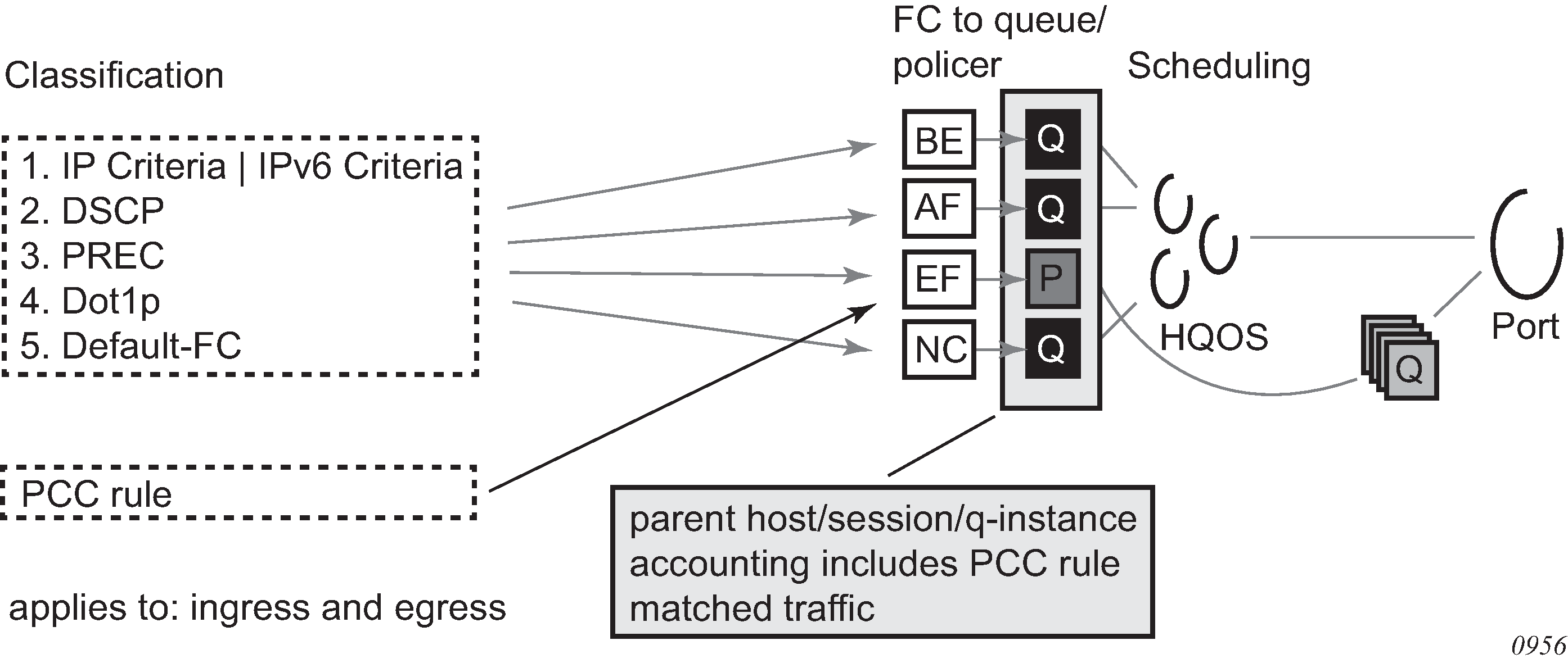
For subscriber service PCC rule QoS actions that result in the instantiation of a dynamic policer (such as rate-limit or account), the dynamic policer counters are not included in the aggregate counters nor are they reported as separate detailed policer statistics. Instead, the traffic matching the PCC rules is counted in the output queues that correspond to the forwarding class of the packets.
On ingress, the dynamic policer PCC rule traffic is never included in the parent host, session, or queue instance accounting session counters. Ingress policed traffic always uses the ingress shared policer output queues, as shown in PCC rule-based subscriber service—QoS interaction: dynamic policer to ingress shared policer output queues.
Figure 82. PCC rule-based subscriber service—QoS interaction: dynamic policer to ingress shared policer output queues 
To include the egress dynamic policer PCC rule traffic in the parent host, session, or queue instance accounting session counters, the dynamic policer must use a local subscriber output queue, as shown in PCC rule-based subscriber service—QoS interaction: dynamic policer, FC to queue (egress).
Figure 83. PCC rule-based subscriber service—QoS interaction: dynamic policer, FC to queue (egress) 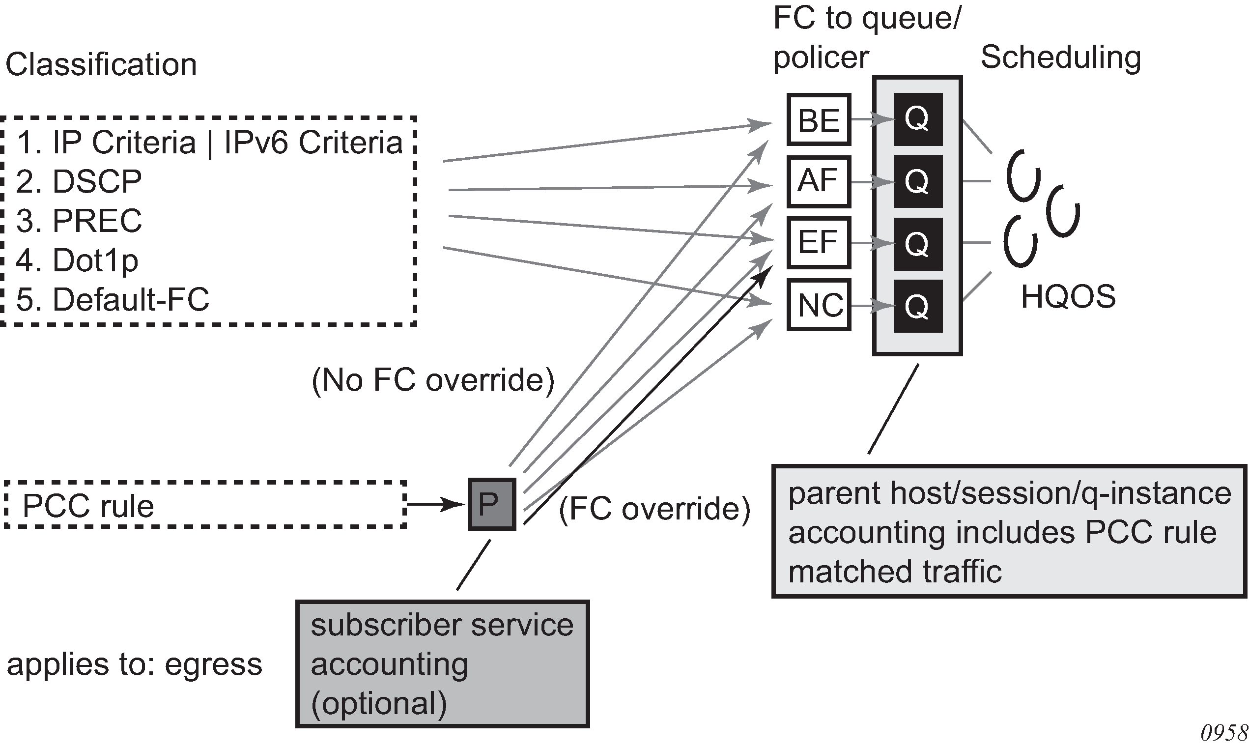
To exclude the egress dynamic policer PCC rule traffic from the parent host, session, or queue instance accounting session counters, the dynamic policer must use a queue-group output queue, as shown in PCC rule-based subscriber service—QoS interaction: dynamic policer, FC to policer to policer output queues (egress). The dynamic policer traffic inherits the policer-to-output queue mapping from the static policer that corresponds to the forwarding class of the packet. The following SAP egress configuration example uses the default policer output queue-group:
config>qos
    sap-egress 10 create
       sub-insert-shared-pccrule start-entry 200 count 10
        dynamic-policer
            range start-entry 10 count 10
        exit
        policer 1 create
        exit
        fc be create
            policer 1
        exit
    exit
If a packet is classified as FC = Best Effort (BE) and matches a PCC rule with rate-limit action only (no FC change), the traffic hits the PCC rule dynamic policer and then the queue-group queue associated with policer 1 (the static policer for FC = BE).
Figure 84. PCC rule-based subscriber service—QoS interaction: dynamic policer, FC to policer to policer output queues (egress) 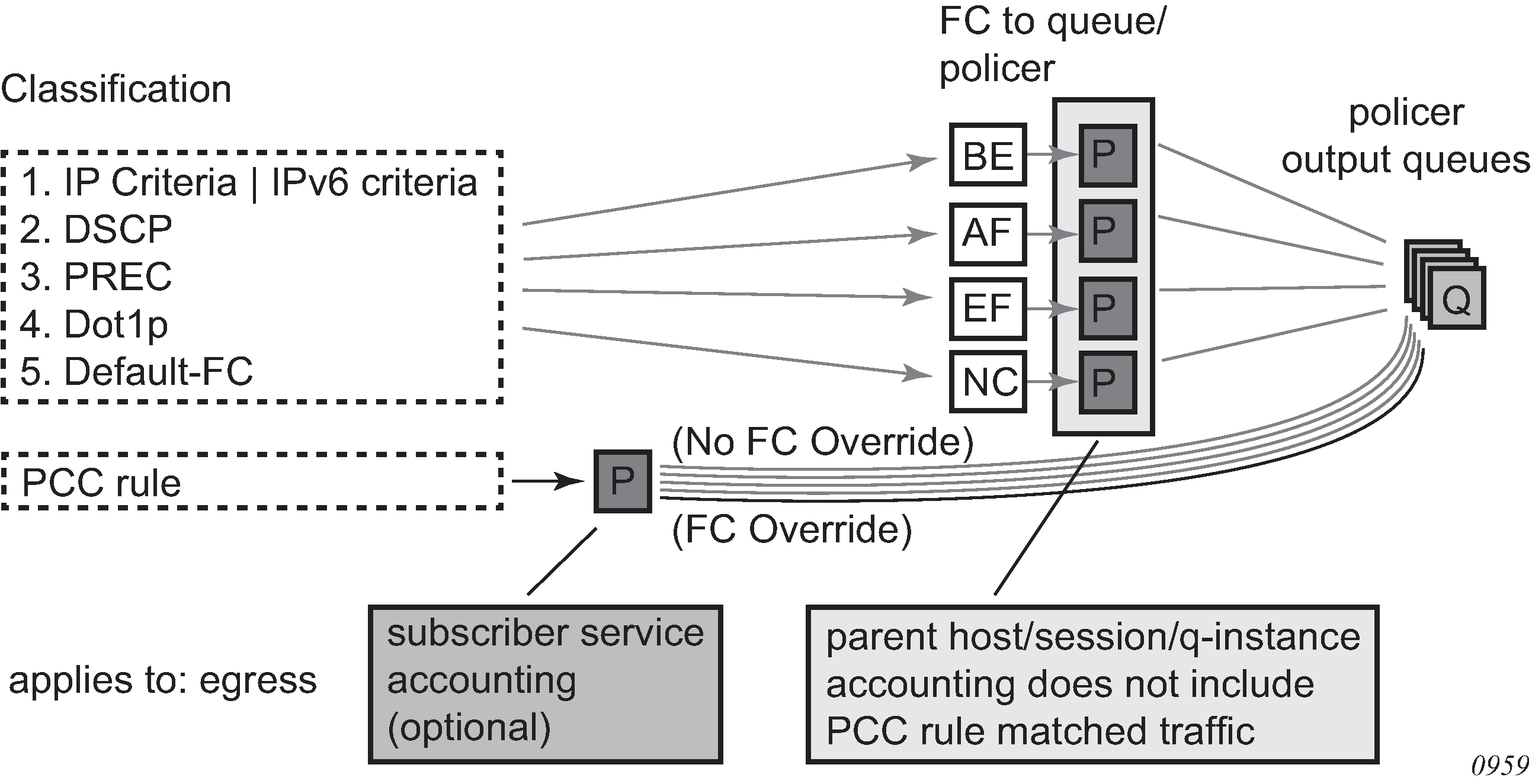
A special case occurs when, at egress, the forwarding class maps to a static policer and then to a local subscriber queue. Traffic for that forwarding class hitting a dynamic policer uses the local subscriber queue as the output queue. In this case, the dynamic policer PCC rule traffic is included in the parent host, sessions or queue instance accounting session counters. This is shown in PCC rule-based subscriber service—QoS interaction: dynamic policer, FC to policer to local queue (egress).
Figure 85. PCC rule-based subscriber service—QoS interaction: dynamic policer, FC to policer to local queue (egress) 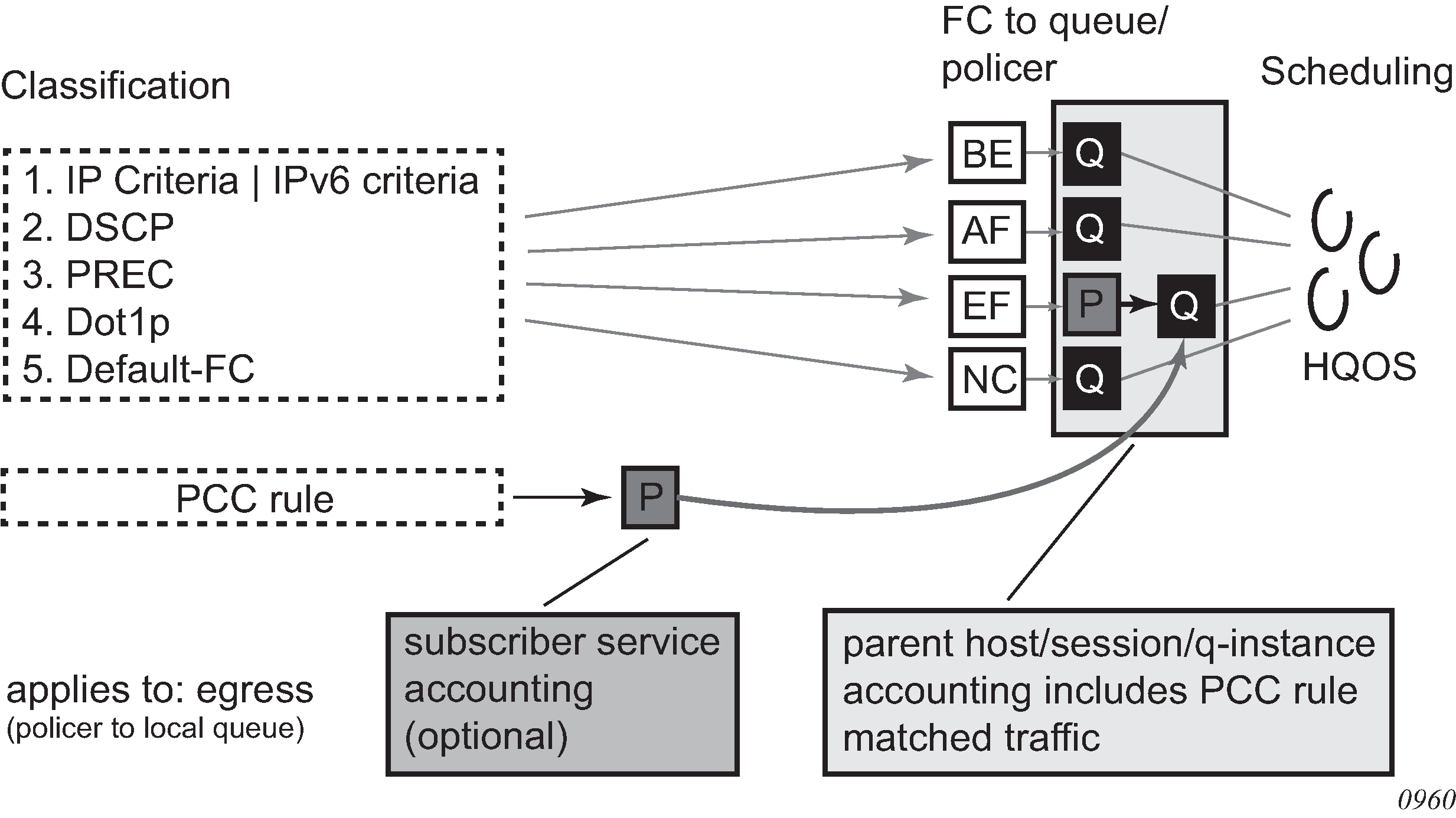
PCC rule-based subscriber service activation failures
PCC rule-based subscriber service activation failures can be categorized as failures detected in the subscriber services Python script as runtime errors (see PCC rule-based subscriber service: Python runtime errors ) and failures detected in the Enhanced Subscriber Management (ESM) processing (see PCC rule-based subscriber service: ESM — RADIUS decoding failures and PCC rule-based subscriber service: ESM — processing failures).
| Python runtime errors |
|---|
Pcc rule name type must be a string |
Pcc rule name value too long |
Pcc rule qos action account value must be True(1) or False(0) |
Pcc rule filter action redirect to nexthop_v4/v6 type must be a string |
Pcc rule filter action redirect to nexthop_v4/v6 value must be a valid IPv4/v6 address |
Pcc rule filter action http redirect value is not a valid URL |
Pcc rule filter action http redirect type must be a string |
Pcc rule filter action http redirect value too long (> 255) |
Pcc rule qos action fwd class change value is invalid |
Pcc rule qos action rate limit type must be an int |
Pcc rule precedence type must be an int |
Pcc rule flow dscp match type must be a string |
Pcc rule flow dscp match value is invalid |
Pcc rule flow src/dst_ip match type must be a string: <ipv4-address>|<ipv6-address>|any |
Pcc rule flow src/dst_ip match value is not a valid IP address: <ipv4-address>|<ipv6-address>|any |
Pcc rule flow port match type must be a string: <port>[-<port>] with port [0..65535] |
Pcc rule flow protocol match type must be an int |
Pcc rule flow protocol match value must be less than 255 |
Pcc rule must have a name |
| ESM — RADIUS decoding failures |
|---|
The PCC rule precedence must be in the range 0 to 65535. |
The PCC rule name has a maximum of 100 displayable characters. |
The PCC rule redirect URL has a maximum of 255 displayable characters. |
All flows in a PCC rule must have the same direction (ingress or egress). |
A PCC rule has a maximum of 128 flows. |
A PCC rule name can occur only one time in a RADIUS message. |
A flow in a PCC rule cannot have a mix of IPv4 and IPv6 addresses (for example src-ip and dst-ip). |
| ESM — processing failures |
|---|
|
If a PCC rule contains a direction-specific action (such as a redirect), it must contain at least one flow in that direction. |
|
If a PCC rule contains only IPv4 actions (such as a redirect to an IPv4 next hop), it must contain at least one IPv4 flow. This also applies to IPv6. |
|
The combinations of PCC rule actions must be supported (see Supported combinations of ingress PCC rule actions and Supported combinations of egress PCC rule actions). |
|
There must be at least one flow and at least one action per PCC rule. |
|
There is a maximum of 64 PCC rules per host or session. |
|
There are not enough filter or QoS resources to create policy clones or apply them to the host or session. |
|
The filter or QoS policy clone cannot be created (for example, the redirect service does not exist). |
|
Simultaneous provisioning of PCC rules from Gx and RADIUS is operationally blocked per subscriber session/host. |
Combined subscriber services
A subscriber service instance can be built with a combination of QoS override actions and PCC rules. In this case, the reported volume counters for subscriber service statistics type volume-time are determined by the PCC rule account action, as shown in Subscriber service accounting—reported volume counters .
| QoS override | PCC rule | Reported volume counters |
|---|---|---|
No |
No |
Aggregated SLA profile queue and policer statistics |
Yes |
No |
Aggregated SLA profile queue and policer statistics |
No |
Yes, ‟pccrule.qos_action_account = False” for all PCC rules |
Aggregated SLA profile queue and policer statistics |
No |
Yes, ‟pccrule.qos_action_account = True” for at least one PCC rule |
Dynamic policer statistics for PCC rules with ‟pccrule.qos_action_account = True” |
Yes |
Yes, ‟pccrule.qos_action_account = False” for all PCC rules |
Aggregated SLA profile queue and policer statistics |
Yes |
Yes, ‟pccrule.qos_action_account = True” for at least one PCC rule |
Dynamic policer statistics for PCC rules with ‟pccrule.qos_action_account = True” |
Subscriber services Python API
The SR OS alc.sub_svc Python module offers functions and data structures to describe, activate, and deactivate a subscriber service.
Common subscriber services Python API
Subscriber service functions in the alc.sub_svc module lists the subscriber service functions in the alc.sub_svc module.
| sub_svc functions | Description |
|---|---|
sub_svc.add_to_service (svc, sub_svc TLV, value) |
Appends a TLV to the service list. The service list describes the subscriber service and should be passed to the sub_svc.commit_service() to activate or deactivate the subscriber service. Parameters: svc (type = list): service list that describes the subscriber service. sub_svc TLVs are appended to this list with the sub_svc.add_to_service() function. sub_svc TLV (type int): TLV that is appended to the service list value (type as defined for the sub_svc TLV): the value of the sub_svc TLV that is appended to the service list |
sub_svc.commit_service (svc) |
Creates the required internal VSAs based on the TLVs provided in the svc list. Parameters: svc (type = list): service list that describes the subscriber service. sub_svc TLVs are appended to this list with the sub_svc.add_to_service() function. The service list should be passed to sub_svc.commit_service() to activate or deactivate the subscriber service. |
Subscriber service TLVs in the alc.sub_svc module lists the subscriber service TLVs in the alc.sub_svc module.
| sub_svc TLV | Activate/ deactivate | TLV details | |
|---|---|---|---|
name (string) |
M/M |
Purpose |
The unique subscriber service instance identifier (key). This field is matched for a subscriber service deactivate request. This field could, for example, be populated with the service-name and corresponding parameter list. This value is also echoed in the Alc-Sub-Serv-Session attribute in accounting messages. When not specified, the subscriber service activation fails and an event log is generated: WARNING: SVCMGR #2511 Base RADIUS CoA Error ‟Problem encountered in Subscriber Management, while processing a CoA request from a RADIUS server: Could not decode RADIUS Attribute ‟Sub Service””. |
Value |
Free format string (max. length = 1000 bytes) |
||
Default |
Empty string |
||
operation (int) |
M/O |
Purpose |
Specifies if the referenced subscriber service should be activated or deactivated |
Value |
operation_add (1): activate the subscriber service instance operation_del (2): deactivate the subscriber service instance |
||
Default |
operation_del |
||
acct_stats_type (int) |
O/n.a. |
Purpose |
Defines if RADIUS accounting should be enabled for this subscriber service instance. If enabled, the accounting mode (Time or Volume and Time) is specified. Values as defined for Alc-Sub-Serv-Acct-Interim-Ivl VSA |
Value |
Off (1) Volume-time (2) Time (3) |
||
Default |
Off |
||
acct_interval (int) |
O/n.a. |
Purpose |
Defines the RADIUS interim accounting update interval for this subscriber service instance Values as defined for Alc-Sub-Serv-Acct-Interim-Ivl VSA |
Value |
0 (no interim updates) 1 to 299 (rounded to a maximum 300 seconds) 300 to 15552000 (override the local configured update-interval for this subscriber service instance) |
||
Default |
Update interval from the parent subscriber RADIUS accounting policy |
||
type (string) |
O/n.a. |
Purpose |
Grouping of subscriber service instances that belong to the same PPPoE or IPoE session |
Value |
Free format string (max. length = 255 bytes) |
||
Default |
empty string |
||
type_conflict_action (int) |
O/n.a. |
Purpose |
Defines the action when another subscriber service instance of the same type is already activated for the same PPPoE or IPoE session. |
Value |
type_conflict_action_keep_old (1): reject the new subscriber service instance type_conflict_action_keep_new (2): deactivate the old and activate the new subscriber service instance type_conflict_action_none (3): allow multiple subscriber service instances of this type |
||
Default |
type_conflict_action_none |
||
Note: M=Mandatory, O=Optional, n.a.=ignored
Subscriber service QoS override Python API
QoS override TLVs in the alc.sub_svc module lists the QoS override TLVs in the alc.sub_svc module.
| sub_svc TLV | Activate/ deactivate | TLV details | |
|---|---|---|---|
qos_override (string) |
O/n.a. |
Purpose |
Adds a QoS override to the subscriber service. Multiple qos_override TLVs can be added in a single subscriber service instance. |
Value |
As defined for the RADIUS Alc-Subscriber-QoS-Override VSA [26-6527-126]. See the 7450 ESS, 7750 SR, and VSR RADIUS Attributes Reference Guide for details. |
||
Default |
Not included |
||
Note: M=Mandatory, O=Optional, n.a.=ignored
Subscriber service PCC rules Python API
PCC Rule TLVs in the alc.sub_svc module lists the PCC rule PLVs in the alc.sub_svc module.
| sub_svc TLV | Activate/ deactivate | TLV details | |
|---|---|---|---|
pccrule (list) |
O/n.a. |
Purpose |
Adds a PCC rule to the subscriber service. Multiple PCC rule TLVs can be added in a single subscriber service instance. |
Value |
A PCC rule list describing the PCC rule with PCC rule TLVs such as name, precedence, direction, flows, and actions PCC rule TLVs are appended to the PCC rule list with the sub_svc.pccrule.add_to_pccrule() function. |
||
Default |
Not included |
||
Note: M=Mandatory, O=Optional, n.a.=ignored
alc.sub_svc.pccrule Function lists the alc.sub_svc.pccrule function.
| alc.sub_svc.pccrule function | Description |
|---|---|
sub_svc.pccrule.add_to_pccrule (pccrule, pccrule TLV, value) |
Appends a PCC rule TLV such as name, precedence, flow, or action to the PCC rule list. The PCC rule list describes the PCC rule and can be added to a subscriber service with the sub_svc.add_to_service() function. Parameters: pccrule (type = list): PCC rule list that describes the PCC rule. PCC rule TLVs are appended to this list with the sub_svc.pccrule.add_to_pccrule() function. pccrule TLV (type int): PCC rule TLV that is appended to the PCC rule list value (type as defined for the PCC rule TLV): the value of the PCC rule TLV that is appended to the PCC rule list |
PCC Rule TLVs in the alc.sub_svc.pccrule module lists the PCC rules TLVs in the alc.sub_svc.pccrule module.
| PCC rule TLV | M|O | TLV details | |
|---|---|---|---|
pccrule.name (String) |
M |
Purpose |
Specifies the name of the PCC rule A PCC rule with the same name and same or different content can only be applied one time on a single parent PPPoE or IPoE session. A PCC rule with the same name and same or different content can be applied on different parent PPPoE or IPoE sessions. Rules with the same name but different content gets a different PCC rule identifier (rule id). |
pccrule.precedence (Integer) |
O |
Purpose |
Specifies the precedence value for the PCC rule. The precedence defines a relative order of the different PCC rules: a rule with a lower precedence value is applied before a rule with a higher precedence value. Rules with the same precedence and rules without precedence can be automatically optimized; the relative order in which they are applied is determined by the system for optimal sharing. |
Value |
0 to 65535 |
||
Default |
n/a These rules are applied at the end. |
||
pccrule.direction (Integer) |
M |
Purpose |
Specifies the direction of the PCC rule: ingress or egress |
Value |
direction_ingress (1) |
||
direction_egress (2) |
|||
Default |
n/a |
||
pccrule.flow (list) |
M |
Purpose |
Adds a flow to the PCC rule. At least one flow must be added to a PCC rule. Multiple flow TLVs can be added to a PCC rule. |
Value |
A flow list describing the flow with flow TLVs such as dscp, protocol, src-ip, dst-ip, src-port, and dts-port Flow TLVs are appended to the flow list with the sub_svc.flow.add_to_flow() function. |
||
Default |
Not included |
||
pccrule.qos_action_ account (Boolean) |
O (1) |
Purpose |
PCC rule action: account Can be applied on ingress and egress Results in IPv4 or IPv6 criteria entry in QoS policies. When set to True: if no rate-limit action is specified, a dynamic policer with pir=cir=max is instantiated for all flows in the PCC rule CLI equivalent: The forwarded octets and packets statistics of the dynamic policer associated with this PCC rule are included in subscriber service accounting. |
Value |
True (1) False (0) |
||
Default |
False |
||
pccrule.qos_action_ change_fc (string) |
O (1) |
Purpose |
PCC rule action: change the forwarding class Can be applied on ingress and egress. Results in IPv4 or IPv6 criteria entry in QoS policies CLI equivalent: |
Value |
String with fixed format forwarding class name: ‟be”, ‟l2”, ‟af”, ‟l1”, ‟h2”, ‟ef”, ‟h1” or ‟nc” |
||
Default |
n/a |
||
pccrule.qos_action_ rate_limit_cir (Integer) |
O (1) |
Purpose |
PCC rule action: rate-limit CIR
Can be applied on ingress and egress. Results in IPv4 or IPv6 criteria entry in QoS policies CLI equivalent: |
Value |
0 to 2000000000 kb/s |
||
Default |
n/a |
||
pccrule.qos_action_ rate_limit_pir (integer) |
O (1) |
Purpose |
PCC rule action: rate-limit PIR
Can be applied on ingress and egress. Results in IPv4 or IPv6 criteria entry in QoS policies. CLI equivalent: |
Value |
1 to 2000000000 kb/s |
||
Default |
None |
||
pccrule.qos_action (integer) |
O (1) |
Purpose |
PCC rule action: QoS forward Can be applied on ingress and egress Results in IPv4 or IPv6 criteria entry in QoS policies CLI equivalent: |
Value |
pccrule.qos_action_forward (1) |
||
Default |
n/a |
||
pccrule.filter_action_http_redirect (string) |
O (1) |
Purpose |
PCC rule action: http-redirect Can be applied on ingress only Results in an IPv4 or IPv6 filter entry CLI equivalent: |
Value |
http-redirect URL string (maximum 255 characters) |
||
Default |
n/a |
||
pccrule.filter_action_ redirect_to_nexthop_v4 (string) |
O (1) |
Purpose |
PCC rule action: redirect to a next-hop IPv4 address Can be applied on ingress only Results in an IPv4 filter entry CLI equivalent: |
Value |
IPv4 address |
||
Default |
n/a |
||
pccrule.filter_action_ redirect_to_nexthop_v6 (string) |
O (1) |
Purpose |
PCC rule action: redirect to a next-hop IPv6 address Can be applied on ingress only Results in an IPv6 filter entry. CLI equivalent: |
Value |
IPv6 address |
||
Default |
None |
||
pccrule.filter_action_ redirect_to_router_v4 (integer) |
O (1) |
Purpose |
PCC rule action: redirect to a routing instance Can be applied on ingress only Results in an IPv4 filter entry CLI equivalent: |
Value |
service-id |
||
Default |
n/a |
||
pccrule.filter_action_ redirect_to_router_v6 (Integer) |
O (1) |
Purpose |
PCC rule action: redirect to a routing instance Can be applied on ingress only Results in an IPv6 filter entry CLI equivalent: |
Value |
service-id |
||
Default |
n/a |
||
pccrule.filter_action (Integer) |
O (1) |
Purpose |
PCC rule action: Filter forward or drop Can be applied on ingress and egress Results in an IPv4 or IPv6 filter entry CLI equivalent: |
Value |
pccrule.filter_action_forward (1) pccrule.filter_action_drop (2) |
||
Default |
n/a |
||
pccrule.policer_parent_arbiter (String) |
O |
Purpose |
Specifies the dynamic policer parent arbiter name for this PCC rule. The reserved value ‟_tmnx_no_parent” sets no arbiter parent for the dynamic policer used in this PCC rule. Overrides the dynamic policer value configured in the sap-ingress or sap-egress QoS policy. |
Value |
Free format string (maximum length = 32 bytes) ‟_tmnx_no_parent” sets no parent arbiter |
||
Default |
None |
||
pccrule.policer_parent_level (Integer) |
O |
Purpose |
Specifies the dynamic policer parent level for this PCC rule. Overrides the dynamic policer value configured in the sap-ingress or sap-egress QoS policy. |
Value |
1 to 8 |
||
Default |
None |
||
pccrule.policer_parent_weight (Integer) |
O |
Purpose |
Specifies the dynamic policer parent weight for this PCC rule. Overrides the dynamic policer value configured in the sap-ingress or sap-egress QoS policy. |
Value |
1 to 100 |
||
Default |
None |
||
pccrule.policer_mbs (Integer) |
O |
Purpose |
Specifies the dynamic policer MBS value in bytes or reset to the default MBS value for this PCC rule. Overrides the dynamic policer value configured in the sap-ingress or sap-egress QoS policy. |
Value |
0 to 16777216 -1 sets the default MBS |
||
Default |
None |
||
pccrule.policer_cbs (Integer) |
O |
Purpose |
Specifies the dynamic policer CBS value in bytes or resets to the default CBS value for this PCC rule. Overrides the dynamic policer value configured in the sap-ingress or sap-egress QoS policy. |
Value |
0 to16777216 -1 sets the default CBS |
||
Default |
None |
||
pccrule.policer_stat_mode (Integer) |
O |
Purpose |
Specifies the dynamic policer stat-mode for this PCC rule. Overrides the dynamic policer value configured in the sap-ingress or sap-egress QoS policy. |
Value |
Note that integer values are mapped to each of the stats-mode. ingress:
egress:
|
||
Default |
None |
||
pccrule.policer_packet_byte_offset (Integer) |
O |
Purpose |
Specifies the dynamic policer packet-byte-offset for this PCC rule. Setting the value to zero (0) sets no packet-byte-offset. Overrides the dynamic policer value configured in the sap-ingress or sap-egress QoS policy. |
Value |
ingress: -32 to +31 egress: -64 to +31 |
||
Default |
None |
||
Notes:
(1) At least one PCC rule action must be specified.
M=Mandatory, O=Optional
alc.sub_svc.flow functions lists the alc.sub_svc.flow function.
| alc.sub_svc.flow functions | Description |
|---|---|
sub_svc.flow.add_to_flow (flow, flow TLV, value) |
Appends a flow TLV such as dscp, protocol, src-ip, dst-ip, src-port, or dst-port to the flow list. The flow list defines matching criteria for an IP flow and can be added to a PCC rule with the sub_svc.pccrule.add_to_pccrule() function. Parameters: flow (type = list): list containing the match criteria (DSP, 5-tuple) that describes an IP flow. Flow TLVs are appended to this list with the sub_svc.flow.add_to_flow() function. The flow is added to a PCC rule with the sub_svc.pccrule.add_to_pccrule() function. flow TLV (type int): Flow TLV that is appended to the flow list. value (type as defined for the flow TLV): the value of the flow TLV that is appended to the flow list |
PCC rule TLVs alc.sub_svc.flow module lists the PCC Rule TLVs alc.sub_svc.flow Module.
| Flow TLV | M|O | TLV details | |
|---|---|---|---|
flow.dscp (string) |
O |
Purpose |
Specifies a DSCP flow match criterion |
Value |
Fixed DSCP name strings as in the output of show qos dscp-table; for example, ‟be” or ‟ef”. The DSCP name must be specified in lowercase. |
||
Default |
n/a |
||
flow.protocol (integer) |
O |
Purpose |
Specifies a protocol number match criterion |
Value |
0 to 255 |
||
Default |
n/a |
||
flow.dst-ip (string) |
O |
Purpose |
Specify a destination IPv4 or IPv6 match criterion |
Value |
ipv4-address | ipv6-address | any where ipv4-address: d.d.d.d[/m] d [0 to 255] m [0 to 32] ipv6-address: x:x:x:x:x:x:x:x[/preflen] x: [0 to FFFF] preflen: 0 to 128 |
||
Default |
any |
||
flow.dst-port (string) |
O |
Purpose |
Specify a destination port match criterion |
Value |
port or port range: port[-port] where port: 0 to 65535 |
||
Default |
n/a |
||
flow.src-ip (string) |
O |
Purpose |
Specify a source IP or IPv6 match criterion |
Value |
ipv4-address | ipv6-address | any where ipv4-address: d.d.d.d[/m] d [0 to 255] m [0 to 2] ipv6-address: x:x:x:x:x:x:x:x[/preflen] x: [0 to FFFF] preflen: 0 to 128 |
||
Default |
any |
||
|
flow.src-port (string) |
O |
Purpose |
Specifies a source port match criterion |
Value |
port or port range: port[-port] where port: 0 to 65535 |
||
Default |
n/a |
||
Operational commands
Show commands
To display the active subscriber services in the system, use the show service sub-services CLI command. The sub-service-name filter is a longest match.
# show service sub-services [id <service-id>] [sap <sap-id>] [ip <ip-prefix/prefix-length>] [mac <ieee-address>] [pppoe-session-id <pppoe-session-id>] [sub-service-name <sub-service-name>] [sub-service-type <sub-service-type>] [summary|associations]
Sample output:
# show service sub-services
===============================================================================
Subscriber service table
===============================================================================
Username : cpe2@domain1.com
Subscriber : cpe2@domain1.com Type : PPP
SAP : 1/1/4:1201.5 Service : 1000
MAC Address : 00:51:00:00:01:01 PPPoE-SID: 114
IP : 10.1.1.3
Interface-ID : 02:51:00:FF:FE:00:01:01
-------------------------------------------------------------------------------
Service instance : rate-limit;5120;30720
up time : 0d 00:05:23
type : rate-limit
acct sess id : 144DFF00000A2556B757DA
multi sess id : 144DFF00000A1156B71E44
acct type : volume-time
acct ivl : 1d 00:00:00
input octets : 0
input packets : 0
output octets : 0
output packets : 0
actions :
QoS-override
ingress arbiter "root" rate 5120
QoS-override
egress aggregate rate limit 30720
-------------------------------------------------------------------------------
number of subscriber services found: 1
===============================================================================
To display the active PCC rules in the system, use the show service active-subscribers pcc-rule CLI command. A PCC rule can be inactive when, for example, a PCC rule with filter actions on IPv6 flows is activated on an IPv4single-stack PPPoE or IPoE session.
# show service active-subscribers pcc-rule [subscriber <sub-ident-string>] [detail]
Sample output:
# show service active-subscribers pcc-rule subscriber "ipoe-bridged-001" detail
===============================================================================
Active Subscribers
===============================================================================
-------------------------------------------------------------------------------
Subscriber ipoe-bridged-001 (sub-profile-1)
-------------------------------------------------------------------------------
-------------------------------------------------------------------------------
(1) SLA Profile Instance sap:[1/1/4:1201.19] - sla:sla-profile-1
-------------------------------------------------------------------------------
IP Address
MAC Address Session Origin Svc Fwd
-------------------------------------------------------------------------------
2001:db8:1:101::1/128
00:51:00:00:00:05 IPoE DHCP6 1000 Y
-------------------------------------------------------------------------------
Ingr Filter Override : N/A
Egr Filter Override : N/A
Ingr Qos Policy Override : 10:P10
Egr Qos Policy Override : 10:P9
===============================================================================
Precedence Rule Id Rule Name Subscriber Service Name
-------------------------------------------------------------------------------
10 19 rule-1 subsvc_pcc-coa-1
10 20 rule-2 subsvc_pcc-coa-1
===============================================================================
===============================================================================
PCC Rules
===============================================================================
PCC rule name : rule-1
PCC rule id : 19
Monitoring key : -
Flow status : Enabled
Nbr of Flows : 2 (ingress)
HTTP-Redirect : -
Next-Hop Redir. IPv4 : -
Next-Hop Redir. IPv6 : -
QoS Ingr. CIR/PIR : - / 1000 kbps
QoS Egr. CIR/PIR : - / -
FC change : -
Account : Enabled
-------------------------------------------------------------------------------
Flows
-------------------------------------------------------------------------------
Src. IP : any Src. Port: -
Dst. IP : 172.16.1.1/32 Dst. Port: -
Protocol : - DSCP : -
-------------------------------------------------------------------------------
Src. IP : any Src. Port: -
Dst. IP : 2001:db8:aaa:1::1/128 Dst. Port: -
Protocol : - DSCP : -
-------------------------------------------------------------------------------
===============================================================================
PCC rule name : rule-2
PCC rule id : 20
Monitoring key : -
Flow status : Enabled
Nbr of Flows : 2 (egress)
HTTP-Redirect : -
Next-Hop Redir. IPv4 : -
Next-Hop Redir. IPv6 : -
QoS Ingr. CIR/PIR : - / -
QoS Egr. CIR/PIR : - / 5000 kbps
FC change : -
Account : Enabled
-------------------------------------------------------------------------------
Flows
-------------------------------------------------------------------------------
Src. IP : 172.16.1.1/32 Src. Port: -
Dst. IP : any Dst. Port: -
Protocol : - DSCP : -
-------------------------------------------------------------------------------
Src. IP : 2001:db8:aaa:1::1/128 Src. Port: -
Dst. IP : any Dst. Port: -
Protocol : - DSCP : -
-------------------------------------------------------------------------------
===============================================================================
-------------------------------------------------------------------------------
-------------------------------------------------------------------------------
Use the following alternative command to check the PCC rules in the system:
# show subscriber-mgmt pcc-rule
- pcc-rule
- pcc-rule monitoring-key <key> detail
- pcc-rule rule-id <id> detail
- pcc-rule rule-name <rule-name>
- pcc-rule rule-name <rule-name> detail
- pcc-rule summary
- pcc-rule monitoring-key <key>
<rule-name> : [100 chars max]
<key> : [80 chars max]
<id> : [1..1023]
<detail> : keyword
The statistics of dynamic policers can be displayed with:
# show service active-subscribers subscriber "ipoe-bridged-001" detail
--- snip ---
------------------------------------------------------------------------
SLA Profile Instance per Policer statistics
------------------------------------------------------------------------
Packets Octets
--- snip ---
Ingress Policer 10 (Stats mode: minimal)
used by pcc-rule rule-1
Off. All : 0 0
Dro. All : 0 0
For. All : 0 0
--- snip ---
The details of the cloned QoS and filter policies as a result of PCC rule activation can be displayed with the following show commands:
# show qos sap-ingress 10:P1
# show qos sap-egress 10:P1
# show filter ip 10:P1
# show filter ipv6 "10:P1"
Debug commands
There are no specific RADIUS subscriber services debug commands. The debugging is part of the RADIUS and Python debug output; for example:
debug
router "Base"
radius
packet-type authentication accounting coa
detail-level high
exit
exit
python
python-script "subsvc-1"
script-all-info
exit
exit
exit
Resource monitoring
For information about resource monitoring, see PCC Rules and Capacity Planning and PCC Rule Scaling Example.
The following CLI command provides an overview of the resource usage per line card, such as the number of ACL and ACL QoS entries, Filters, QoS policies, dynamic policers, and QoS overrides:
# tools dump resource-usage card [<slot-number>] all
These resource counters are available in SNMP and can be used in RMON to trigger threshold crossing alarms; for example:
configure system
thresholds
rmon
alarm 1 variable-oid tFPResIngIPv6AclEntryAlloc.1.1.1 interval 10 rising-event 1 rising-threshold 25000 falling-event 2 falling-threshold 24000
event 1 description "Ingress IPv6 ACL Entries too high"
event 2 description "Ingress IPv6 ACL Entries - below limit"
exit
The summary output of the show subscriber-mgmt pcc-rule command lists the number of active PCC rules and the number of active combinations:
# show subscriber-mgmt pcc-rule summary
===============================================================================
PCC Rules Summary
===============================================================================
Total Nbr PCC Rules : 2 / 1024
Nbr Active PCC Rules : 2 / 1024
Nbr Active Combinations
IPv4 Filter : 0 / 4095
IPv6 Filter : 0 / 4095
Egress Qos : 1 / 4095
Ingress Qos : 1 / 4095
===============================================================================
Residential gateway replacement
Residential gateway (RG) replacements are performed for a variety of reasons such as upgrading hardware, replacing broken equipment, or relocating to a new home. However, the BNG’s anti-spoof filter and host-limit features can sometime prevent immediate RG replacement. In some cases, a subscriber must wait for an old DHCP lease to expire before a new RG can connect to the BNG. For example, some service providers assign an IP address and prefix based on physical line, sap-id, circuit-id, or interface-id. Therefore, a home is always assigned the same IP address and prefix. On the BNG, an anti-spoof mechanism prevents different MAC addresses from using the same IP address. As a result, the new RG fails the anti-spoof filter and is denied an IP address and/or prefix. The subscriber in this case must wait for the DHCP lease of the RG to time out for the anti-spoof filter to remove its entry.
Two features, lease-override and shcv-policy, may help improve the RG replacement process. These features focus on minimizing service interruption and enhancing the end subscriber experience. RGs, in general, have no mechanisms to inform the BNG or the DHCP server that they have been disconnected from the network. Even if the BNG has periodic SHCV enabled, the detection may take some time. Often, when a subscriber plugs in a new RG, the BNG still has the old RG registered as a host. This has two consequences. First, if the new RG is assigned the same IP address as the old RG, then an IP-conflict occurs and fails the anti-spoof filter. Second, if the SAP has a host limit or a session limit provisioned, then exceeding the limit prevents the new RG from receiving an IP address or prefix.
Starting in Release 13.0R4, if an IP conflict occurs on the same SAP, then by default the new RG (MAC) immediately overrides the DHCP lease of the old device. This is known as lease-override. This is applicable to DHCP relay and proxy for both IPv4 and IPv6 hosts. Before Release 13.0.R4, lease-override only occurred for DHCPv4 relay. The lease-override is performed only when an IP conflict occurs within the same SAP.
The other option is to use trigger SHCV to check the connectivity status of the old RG before removing it and its lease. This is known as the ip-conflict-triggered SHCV under the SHCV policy. The SHCV is sent only when the BNG detects an IP address conflict on DHCP discovery. If the host does not respond within the configured timeout, both the host and lease are removed from the BNG. The new RG is required to perform a subsequent DHCP discovery or request to install a host. SHCV can help prevent malicious RGs from spoofing another RG IP address. Trigger SHCV for IP-conflict is available for DHCPv4/v6 relay and proxy, as well as ARP hosts. The following table specifies when the SHCV is sent for IP-conflict.
| Configuration on group interface | Triggered on |
|---|---|
DHCPv4 proxy |
DHCP Discovery |
DHCPv4 relay |
DHCP Request |
DHCPv6 proxy |
DHCP Advertisement |
DHCPv6 relay |
DHCP Advertisement |
ARP-host |
Host’s initial ARP |
It is also possible that new RGs are denied service as a consequence of a set of host limits against the subscriber including sla-profile host-limits and session-limits, sub-profile host-limits and session-limits, ipoe session-limit, and ipoe sap-session limits. For example, setting a host limit of overall 1 can ensure that each home only takes one IP address. As mentioned before, RGs do not inform the BNG of a disconnect. If SHCV is enabled, it may take some time before the BNG is informed of the disconnect. Therefore, when a new RG connects to the BNG, the BNG performs a host-limit check (if configured) against the subscriber. If the old host still has an entry on the BNG and there is a host-limit of overall 1, the new RG is denied an IP address and prefix assignment because it has exceeded the host limit. A trigger SHCV, ‟host-limit-exceeded” inside the SHCV policy can be configured against a group interface. This SHCV is triggered when an over limit is detected. If the existing host registered on the BNG does not respond within the configured timeout, both the host and its lease are removed from the BNG. The SHCV can only remove hosts from the BNG and the new RG is still required to perform a subsequent DHCP discoveries or requests to obtain an IP address.
By providing lease-override and various SHCV triggers in the SHCV policy, service providers have a variety of options to allow subscribers to perform quick and seamless RG replacements.
It is possible to use the host-connectivity check without the SHCV policy. The main function of the host-connectivity check is for periodic check. The trigger functions are performed through the SHCV policy.
ESM troubleshooting show command
Network operators are sometimes unable to turn on debug to troubleshoot customers issues on a live production network. Turning on debug may affect the BNG performance, and some support technicians may not have access to debug and configuration commands.
The show subscriber-mgmt errors command is a show command that captures detailed ESM errors. This command helps diagnose problems immediately without the need to turn on the debug function. Only DHCPv4 and PPPv4 supports this command; some support details are provided below. This command does not compromise the BNG performance and does not require debug or configuration commands.
DHCPv4 support:
dropped protocol messages (host setup/renew)
protocol timeouts
PPPoEv4 support:
dropped protocol messages
traps
IPv6 host setup errors may be captured in error logs.
All subscriber problems are first stored in a main circular buffer. The main circular buffer is then fed into smaller circular buffers, organized by MAC addresses. When the buffer is full, the first circular buffer purges the oldest message to make room for the newest message. The smaller circular buffers (one per MAC address) store a limited number of messages per MAC. Again, the smaller buffer deletes the oldest to make room for the newest. The circular buffer, per MAC, prevents one device from holding all the error messages in the buffer. The main circular buffer can hold 5,000 errors in total, while the smaller buffer can hold 10 log entries per MAC. The circular buffer supports CPM3 and higher.
The show command allows sorting by MAC, subscriber SAP, SDP, and unknown-origin (unknown SAP or SDP). The show command allows the input of a specific MAC, SAP, or SDP to directly search for particular subscriber issues or problems.
The circular buffer only logs drop reasons for DHCPv4 and PPPoEv4. Non-error reasons are never logged; for example, a drop because of being in SRRP standby is not logged. The circular buffer has a timestamp associated with each error and the errors are listed beginning with the most recent. Error logs are lost on a HA switchover, and persistency is not supported. There is no throttling mechanism for the same errors; it is possible to fill the circular buffer with the same error message from different MAC addresses.
Subscriber accumulated statistics
The accumulated statistics policy defines which statistics for queues and policers of a particular subscriber should be collected and stored in memory. At the end of the subscriber session, the queue and policer statistics are added to the statistics already stored in memory from previous sessions. This enables operators to view queue and policer statistics even if the subscriber is offline.
The accumulated statistics policy supports up to four ingress and four egress entries. For queue statistics, v4-v6 mode is not supported, where v4 and v6 statistics are always aggregated. For policer statistics, only min-mode is supported.
When a single subscriber has a list of bridge hosts, all hosts are forced to use the same statistics policy. If hosts use a different SLA profile and the operator wants to collect the statistics for all hosts, the statistics policy must encompass all queues and policers for various SLA profiles. If there are multiple SLA profile instances for the same subscriber, the statistics are summed up for each instance on a per policer or queue basis. These statistics are not exchanged between MCS peers. Therefore, for dual-homed hosts, the statistics need to be gathered from all the nodes and then summed up. If a queue or a policer is missing from the accumulated statistics policy in the current subscriber session and offline statistics exist for that entity from previous sessions, these offline stats are lost when the current subscriber session ends.
Cumulative statistics for a subscriber are not persistent; they are only stored in memory and are lost after node reboot (the statistics start at zero).
The show subscriber-mgmt accu-stats subscriber command displays the cumulative statistics for a subscriber. If the subscriber is online, the cumulative statistics consist of the sum of both the subscriber statistics while online and the offline statistics. If the subscriber is offline, the last subscriber session statistics are added to the offline statistics. Cumulative statistics for a subscriber are not persistent. They are only stored in memory and are lost after a node reboot (the statistics start at zero).
When the accumulated statistics policy changes through a subscriber profile override, either through the tools command or through RADIUS, the stored statistics can be affected. If the new SLA profile uses the same queues and policers already stored in memory, these statistics continue to accumulate. Only queues and policers that differ are added and start from zero.
If resources for capturing offline statistics are full, a trap is generated in log 99 to warn the operator. The command show subscriber-mgmt status system shows the number of subscribers using these accumulated statistics and a flag in this command shows whether the usage is at its peak value.
In the show subscriber-mgmt accu-stats-subscribers command, active subscribers with an accumulated statistics policy configured have both the sub-profile-name and accu-stats-policy fields populated. Active subscribers that are no longer associated with an accumulated statistics policy have accu-stats-policy populated with ‟Unknown”. Inactive subscribers have ‟Unknown” for both the sub-profile-name and the accu-stats-policy fields. This command is useful when combined with the CLI match command, to search for subscribers with specified properties. For example, match ‟Unknown” displays the list of subscribers that are no longer associated with any accumulative statistics policy.
It is possible for an active subscriber to have offline statistics without an accumulated statistics policy if the accu-stats-policy was removed from the sub-profile.
When the active subscriber has an accumulated statistics policy, the subscriber’s offline statistics can be deleted using the following command.
clear subscriber-mgmt accu-stats subscriber subscriber-id
The show subscriber-mgmt accu-stats subscriber subscriber-id command then displays only the subscriber’s current statistics as no statistics remain in the offline storage.
If an active subscriber does not have an accumulated statistics policy, the subscriber’s offline statistics can be deleted in one of the following ways.
To remove the offline statistics for all active subscribers that are no longer associated with an accumulated statistics policy, the following command can be used.
clear subscriber-mgmt accu-stats active-subs no-accu-stats-policy
To remove the offline statistics for a group of active subscribers that is no longer associated with an accumulated statistics policy and that has a defined subscriber profile (for example, if the accumulated statistics policy has been removed from the subscriber profile), the following command can be used.
clear subscriber-mgmt accu-stats active-subs sub-profile profile-name
It is also possible to remove the offline statistics for an inactive (offline) subscriber. To remove offline statistics for all inactive subscribers, use the following command.
clear subscriber-mgmt accu-stats inactive-subs
To remove offline statistics for a specific inactive subscriber, use the following command.
clear subscriber-mgmt accu-stats subscriber subscriber-id
Hybrid access
In a hybrid access deployment, a home’s residential gateway (RG) is connected to the network by both a wired and a wireless link. Traffic can be split over these links by various mechanisms such as per-flow hashing, flow policies, or MP-TCP. Both access connections must be terminated in a common endpoint called the Hybrid Access Gateway (HAG). This gateway provides Internet connectivity to the home.
BNG-based HAG
SR OS TPSDA supports hybrid access deployments where the BNG acts as a Serving Gateway (SGW), PDN Gateway (PGW), and HAG. In this model, both the fixed access and wireless access links share the same Layer 3 IP/IPv6 address. The RG/HAG determines which Layer 2 connection should be used. To support this model, SR OS supports GTP termination and ESM connection bonding. The BNG is the Layer 3 gateway in this model and attracts all IP traffic. Multicast traffic is supported.
SGW/PGW/BNG integrated hybrid access gateway shows a sample hybrid access deployment with a BNG-based HAG.

PGW-based HAG
SR OS TPSDA supports hybrid access deployments where a PGW acts as a HAG. In this model, both the fixed access and wireless access links share the same Layer 3 IP/IPv6 address. The RG/HAG determines which Layer 2 connection should be used. To support this model, SR OS IPoE session and PPPoE session functionality is extended to connect to a GTP uplink. When this uplink is active, all unicast traffic is forwarded by a GTP tunnel between the BNG and PGW. This way, the PGW acts as the Layer 3 gateway and the BNG does not attract subscriber traffic by regular routing. Multicast traffic is not supported and should be handled out-of-band.
Sample hybrid access deployment shows a sample Hybrid Access deployment with a PGW-based HAG.

For more details on GTP uplinks, see the GTP section.
Connection bonding
ESM connection bonding allows two Layer 2 access connections, for example, GTP and PPPoE, to combine to share a single Layer 3 IP connection. This allows the seamless use of two connections for additional bandwidth or resiliency without the need to manage multiple IP addresses.
SR OS spreads downstream traffic, either based on fixed weights, a filter decision, a pure active/standby, or dynamic load-balancing that attempts to saturate one link before using another link. Upstream traffic can enter through either connection, but it is recommended to keep flows identified by 5-tuple on the same link to avoid reordering.
Connection bonding requires an FPE type of sub-mgmt-extensions.
Setup
During normal authentication, access connections can indicate they are part of a common bonding context by specifying a bonding identifier. When the first connect is set up, an additional authentication phase is started for the bonding context itself. Bonding authentication shows RADIUS-based authentication for bonding of an IPoE and GTP access connection. For simplicity, all access nodes, such as the residential gateway, MSAN, eNodeB, and MME have been identified as a single entity.
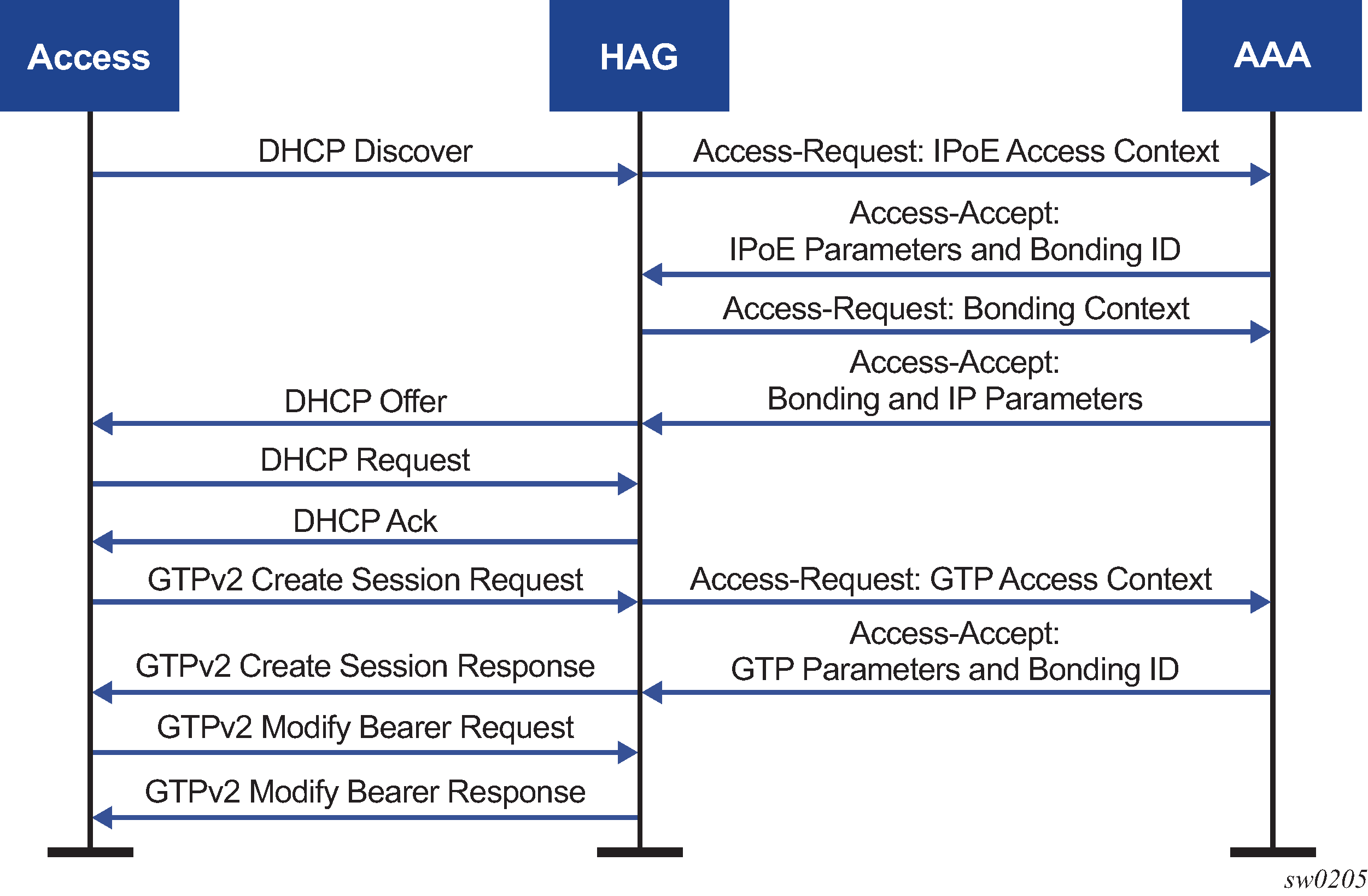
All address assignments and Layer 3 parameters are shared between the access connections and are therefore handled in the bonding context. The system supports either Local Address Assignment or AAA-provisioned IP addresses. Access connections cannot use any DHCPv6 relay or client mechanisms.
After the setup is complete, ESM subscriber resources are created for each context as follows.
a unique subscriber with a single internal IPoE session to represent the bonding context
This is the main context for functionality, including QoS, filters, and accounting. This subscriber cannot be reused for any other hosts, regardless if they are bonding or not.
-
a subscriber per access connection with one or more hosts as needed, depending on the access type
This subscriber must be distinct from the bonding subscriber. Other non-bonded hosts or sessions may be present under the same subscriber. A subset of ESM features (for example, QoS, filters, and accounting) are also available in this context; however, it is recommended that the most of the feature be configured in the bonding context.
All access and bonding ESM contexts need to be present in distinct VRFs. The bonding context must be created in a special group interface of type bonding. This group interface is not linked to any SAPs, however, an FPE construct ensures the link between the access and bonding context.
Downstream load balancing
By default, downstream packets are hashed over two connections on a per-flow basis, allowing packets of the same flow to follow the same path and avoid reordering issues. Flows are identified by the 5-tuple <src-ip, dst-ip, protocol, src-port, dst-port>. The hash weights of each connection are configurable. An IP-filter based selection may be used to override the hash-based connection selection.
The initial hash weights can also be dynamically adapted based on the load on the primary connection. The IOM periodically measures how much traffic is sent over the primary connection, comparing it to a predefined saturation rate. When the connection is saturated, the hash weights automatically change to send more traffic over the alternate link. Similarly, if the total rate of traffic decreases, the hashing weights change to send more traffic over the primary connection.
For dynamic load-balancing, the following must be defined:
the primary connection, identified as connection 1 in the bonding context
the reference rate in the primary connection, which defines the saturation point
By default, the aggregate rate is used, but this can be changed during AAA authentication. The saturation point is further refined using thresholds that define when the rate change should be executed.
a weight change value, specifying how much the weight percentages should change each time the saturation point is reached
policers for all downstream traffic in the bonding context
A single policer that directly feeds into multiple local queues can be used.
When only a single connection is active, all traffic is sent to this connection, regardless of hashing weights or filters.
If one of the two access connections is idle, then the system activates this connection before changing hashing weights. This sequence allows the system to avoid overflowing the packet buffer of the idle connection. For example, for an idle S11 GTP connection, the system reactivates the connection through a network-triggered service request before changing weights.
QoS
Regular ESM QoS is supported in both the access and bonding contexts; however, there is no direct feedback mechanism between the two contexts. Therefore, if an access connection drops a packet, it is not reflected in bonding statistics, nor does it cause backpressure on the bonding QoS algorithm.
When traffic passes over the FPE from the bonding context to the access context or from the access context to the bonding context, the system keeps the traffic classification and the in- and out-profile markings. Although this occurs automatically, bonding subscriber policies for ingress and egress should consider the following recommendations.
Enable de-mark for access egress and map each FC to the dot1p as defined in FC to dot1p mapping, therefore ensuring that the same classification is used in the access connection context.
Perform classification for access ingress based on dot1p as defined in FC to dot1p mapping and enable in-profile and de-1-out-profile for each FC, therefore ensuring the same classification is used as for the access connection context. A different classification scheme can be used if required, for example, based on DSCP or IP criteria.
| FC | dot1p |
|---|---|
be |
0 |
l2 |
1 |
af |
2 |
l1 |
3 |
h2 |
4 |
ef |
5 |
h1 |
6 |
nc |
7 |
To support load-balancing in the bonding context, the configured stat-mode of any egress policer in the bonding context is ignored. Instead, an internal stat-mode is used, which uses two counters (one per access connection), which is reflected in the in- and out-of-profile statistics.
Multicast
Multicast replication is supported in context of the access connections. By default, multicast streams are replicated in the connection where the corresponding IGMP/MLD join is received; however, this can be overridden to always force a specific connection.
When one connection fails, multicast replication automatically sets up in the alternate connection and does not require a new IGMP/MLD packet to arrive.
MCAC bandwidths must be configured equally on both access connections; otherwise, there may be unexpected drops of (S,G) pairs.
If a multicast stream is forwarded over the primary connection and egress-rate-modify is in use, any potential change of the reference rate is taken into consideration by the load-balancing mechanism for unicast traffic as described in Downstream load balancing. When using per-host replication for a bonded host, similar adaptations are made based on channel definitions in applicable MCAC policies.
Ethernet satellites with redundant uplinks
Ethernet satellite (ESAT) ports in the host node are logical ports (for example, esat-1/1/1) that represent physical ports on the remote (satellite) node. ESM in the host node treats ESAT ports similarly to all other physical ports in the system, even without knowing that those ports reside in a remote chassis. An example of an Ethernet satellite configuration is shown in Concept of ESAT.
An SR OS ESAT complex (an SR OS host node with satellite nodes) supports multiple pairs of active and standby uplinks. The supported topologies are described in the following sections.
Single host, single satellite
The following describes a single host and a single satellite topology.
A/S uplinks can be on the same forwarding path (FP) or forwarding complex or on a different FP. An FP refers to a set of chipsets on a line card used to simultaneously forward paired upstream and downstream traffic.
Although a pair of uplinks can be active or standby for the same set of ports, both uplinks can be active for a set of different ports. For example:
| Ports | Active | Standby |
|---|---|---|
esat-1/1/u1 |
satellite ports 1-12 |
satellite ports 13-24 |
esat-1/1/u2 |
satellite ports 13-24 |
satellite ports 1-12 |
Single host, single satellite displays an example of an SR OS host, satellite node and access node.
Single host node, dual satellite
The following describes a single host and dual satellite topology.
Ports 1, 2, 3, and 4 are in the same LAG.
Hashing decisions on ports 1, 2, 3, and 4 are made at ingress on the host node.
Ports 1 and 2 can be reached only through side A.
Ports 3 and 4 can be reached only through side B.
If the active uplink on side A fails, the standby link on the side A becomes the new active uplink servicing the same satellite ports (ports 1 and 2).
If both uplinks on the same side fail, then the corresponding satellite node becomes isolated.
Single host, dual satellite displays an example of an SR OS host, satellite node, and access node.

QoS
Queues and policers in ESM are created on a per SLA profile instance in the host node. A subscriber host resides in a host node on a SAP that is associated with a logical port (mapped to a user port on the satellite node) which is then associated with the physical uplink.
Subscriber aggregate rate and subscriber level schedulers are subscriber-level configurations and therefore, are independent of the ports. However, port schedulers and Vports (agg-rate-limit or port-scheduler) are port level features. They are also created in the host node, on a per-user-port basis (user ports are in the host node represented by a logical ports). They must be manually created per logical port in the host even though those ports may be LAG members.
Buffer pools are the only QoS configurations that are created on a per-physical uplink basis.
Preservation of statistics and accounting in ESM
ESM accounting is based on queue and policer statistics. Consider that queues are recreated and remapped every time a logical port (satellite port) or an uplink for the subscriber is changed, expect that the ESM accounting can be affected by this. If the new uplink is on the same FP as the old, then statistics are preserved. Otherwise, statistics are lost.
Multi-chassis synchronization of RADIUS usage counters
The following section describes multi-chassis synchronization of RADIUS usage counters.
Overview
SR OS supports synchronization of usage counters that can be reported through RADIUS accounting in a dual-homed BNG scenario.
The active (SRRP master state) node keeps the total number of statistics that are reported. The active node synchronizes those statistics in regular intervals with MCS to the standby node. This way, the main copy of the total statistics is maintained on both nodes and failure cases of link, node, and so on, these statistics can be recovered from the surviving node.
MCS interval
The statistics are synchronized at preconfigured intervals (the MCS interval) which are independent of interim-update intervals using the config>subscr-mgmt>acct-plcy>mcs-interval minutes | use-update-interval command. The MCS minutes interval value can also be the same as the interim-update-interval use-update-interval.
If there are multiple RADIUS accounting policies in a subscriber profile, the minimum value of all the configured MCS intervals in these RADIUS accounting policies is used for usage counter synchronization.
Usage counters synchronized
The following SPI-level counters are synchronized:
INPUT OCTETS [42]
OUTPUT OCTETS [43]
ACCT-INPUT-GIGAWORDS [52]
ACCT-OUTPUT-GIGAWORDS [53]
Alc-IPv6-Acct-Input-Octets [26-6527-195]
Alc-IPv6-Acct-Output-Octets [26-6527-198]
Alc-IPv6-Acct-Input-Gigawords [26-6527-196]
Alc-IPv6-Acct-Output-Gigawords [26-6527-199]
In addition to aggregate accounting counters, detailed per queue and policer counters are also synchronized.
The following accounting attributes are synchronized per queue and policer:
Alc-Acct-I-Inprof-Octets-64 [26-6527-19]
Alc-Acct-I-Outprof-Octets-64 [26-6527-20]
Alc-Acct-O-Inprof-Octets-64 [26-6527-21]
Alc-Acct-O-Outprof-Octets-64 [26-6527-22]
Incomplete MCS configuration
After the mcs-interval is configured, statistics are collected or baselined on the CPM even if the configuration to synchronize statistics is not complete (no peer, no sync tag, and so on).
Configuration mismatch
In misconfiguration scenarios when two nodes use different queues or policers, the local configuration wins and decides those queues that are stored or baselined on the CPM.
Switchover scenarios
The following are switchover scenarios.
Node reboot — Because the main copy of the stats is maintained on both nodes, the stats are recovered from the remaining node.
Split brain — A split brain scenario should never occur. If it does, the statistics are reported from both nodes (both in SRRP master state). After the MCS recovers, the statistics are re-synchronized at the regular MCS intervals.
The active node accepts updates received from the other node only when the value of the counter is larger than the local total.
SRRP switchovers— If a host is installed by MCS, and a SRRP switchover occurs before the statistics are retrieved from the active node, the RADIUS accounting messages going out before the statistics are retrieved have unsynced statistics (statistics on a time the node did not yet receive an answer from its peer and is still requesting statistics).
After retrieving the stats, retrieved and unsynced counter values are compared and the higher counter value is chosen for accounting.
Configuring ESM with CLI
This section provides information to configure subscriber management features using the command line interface. It is assumed that the reader is familiar with VPLS and IES services.
Configuring RADIUS authentication of DHCP sessions
When RADIUS authentication for subscriber sessions is enabled, DHCP messages from subscribers are temporarily held by the BSA, while the user’s credentials are checked on a RADIUS server.
Configuring RADIUS authentication for subscriber sessions is done in two steps:
First define an authentication-policy in the config>subscriber-mgmt>authentication-policy context.
Then apply the policy to one or more SAPs in the config>service>vpls>sap>authentication-policy auth-plcy-name context (for a VPLS service).
Or apply the policy to one or more interfaces config>service>ies>if>authentication-policy auth-plcy-name context (for an IES service):
The following example displays a partial BSA configuration with RADIUS authentication:
A:ALA-1>config>service# info
----------------------------------------------
subscriber-management
authentication-policy BSA_RADIUS create
description "RADIUS policy for DHCP users Authentication"
password "mysecretpassword"
radius-authentication-server
server 1 address 10.100.1.1 secret "radiuskey"
retry 3
timeout 10
exit
re-authentication
user-name-format circuit-id
exit
exit
...
vpls 800 customer 6001
description "VPLS with RADIUS authentication”
sap 2/1/4:100 split-horizon-group DSL-group create
authentication-policy BSA_RADIUS
exit
sap 3/1/4:200 split-horizon-group DSL-group create
authentication-policy BSA_RADIUS
exit
no shutdown
exit
...
----------------------------------------------
A:ALA-1>config>service#
TCP MSS adjustment for ESM hosts
TCP MSS adjustment is supported to prevent fragmentation of TCP packets from/to ESM hosts. See the TCP MSS Adjustment for ESM Hosts section of the 7450 ESS, 7750 SR, and VSR Multiservice ISA and ESA Guide.
Configuring ESM
Basic configurations
Configuring and applying the Enhanced Subscriber Management profiles and policies are optional. There are no default Profiles or policies.
The basic Enhanced Subscriber Management profiles and policies must conform to the following:
Unique profile or policy names (IDs).
Profiles and policies must be associated with a VPLS or IES service to facilitate Enhanced Subscriber Management.
QoS and IP filter entries configured in ESM profiles and policies override the defaults and modified parameters or the default policies.
The ESM profiles and policies must be configured within the context of VPLS or IES.
Subscriber interface configuration
The following output displays a basic subscriber interface configuration.
*A:ALA-48>config>service>ies>sub-if# info
----------------------------------------------
description "Routed CO - Antwerp 2018"
address 192.168.2.254/24
address 192.168.3.254/24
address 192.168.4.254/24
address 192.168.5.254/24
address 192.168.6.254/24
group-interface "DSLAM_01" create
description "Routed CO - vlan / subscriber"
sap 1/1/2:1001 create
static-host ip 192.168.2.2 create
exit
sap 1/1/2:1002 create
static-host ip 192.168.2.2 create
exit
sap 1/1/2:1004 create
static-host ip 192.168.2.4 create
exit
sap 1/1/2:1100 create
static-host ip 192.168.2.100 create
exit
exit
exit
----------------------------------------------
*A:ALA-48>config>service>ies>sub-if#
Configuring ESM entities
Configuring a subscriber identification policy
The following displays an example of a subscriber identification policy configuration:
A:ALA-48>config>subscr-mgmt# info
----------------------------------------------
...
sub-ident-policy "Globocom" create
description "Subscriber Identification Policy Id Globocom"
sub-profile-map
entry key "1/1/2" sub-profile "ADSL Business"
exit
sla-profile-map
entry key "1/1/2" sla-profile "BE-Video"
exit
primary
script-url "primaryscript.py"
no shutdown
exit
secondary
script-url "secundaryscript.py"
exit
tertiary
script-url "tertiaryscript.py"
no shutdown
exit
exit
...
----------------------------------------------
A:ALA-48>config>subscr-mgmt#
Configuring a subscriber profile
ESM subscriber profile configurations specify existing QoS scheduler profiles. In the following example, ‟BE-Video-max100M” is specified in the sub-profile ‟ADSL Business” for the ingress-scheduler-policy. ‟Upload” is specified in the sub-profile egress-scheduler-policy.
#--------------------------------------------------
echo "QoS Policy Configuration"
#--------------------------------------------------
qos
scheduler-policy "BE-Video-max100M" create
description "Scheduler Policy Id BE-Video-max100M"
tier 1
scheduler "tier1" create
description "Scheduler Policy Id BE-Video-max100M Tier 1 tier1"
exit
exit
exit
scheduler-policy "Upload" create
description "Scheduler Policy Id Upload"
tier 3
scheduler "tier3" create
description "Scheduler Policy Id Upload Tier 3 tier3"
exit
exit
exit
sap-ingress 2 create
description "Description for Sap-Ingress Policy id # 2"
queue 1 create
parent "tier1"
exit
queue 11 multipoint create
parent "tier1"
exit
exit
sap-egress 3 create
description "Description for Sap-Egress Policy id # 3"
queue 1 create
parent "tier3"
exit
exit
exit
#-----------------------
The following displays an example of a subscriber identification policy configuration:
A:ALA-48>config>subscr-mgmt# info
----------------------------------------------
...
sub-profile "ADSL Business" create
description "Subscriber Profile Id ADSL Business"
ingress-scheduler-policy "BE-Video-max100M"
scheduler "tier1" rate 99
exit
egress-scheduler-policy "Upload"
scheduler "tier3" rate 1 cir 1
exit
sla-profile-map
entry key "1/1/3" sla-profile "BE-Video"
exit
exit
----------------------------------------------
A:ALA-48>config>subscr-mgmt#
Configuring an SLA profile
The following displays an example of a SLA Profile configuration:
A:ALA-48>config>subscr-mgmt# info
--------------------------------------------------
subscriber-mgmt
sla-profile "BE-Video" create
description "SLA Profile Id BE-Video"
ingress
qos 2
queue 1
exit
exit
exit
egress
qos 3
queue 1
exit
exit
exit
exit
----------------------------------------------
A:ALA-48>config>subscr-mgmt#
Configuring explicit mapping entries
The following displays an example of an explicit subscriber mapping:
A:ALA-7>config>subscr-mgmt# info
--------------------------------------------------
A:ALA-48>config>subscr-mgmt# info
----------------------------------------------
...
explicit-subscriber-map
entry key "1/1/1:1111" sub-profile "ADSL GO" alias "Sub-Ident-1/1/1:
1111" sla-profile "BE-Video"
exit
...
----------------------------------------------
A:A:ALA-48>config>subscr-mgmt#
Routed CO with basic subscriber management features
The following displays the output of an IES service configured with and without enhanced subscriber management and only applies to the 7750 SR.
A:term17>config>service>ies# inf
----------------------------------------------
subscriber-interface "s2" create
address 10.20.1.1/16
dhcp
gi-address 10.20.1.1
exit
group-interface "g3" create
description "With Enhanced Subscriber Mgmt"
arp-populate
dhcp
server 10.1.1.1
trusted
lease-populate 8000
no shutdown
exit
sap lag-1:11 create
sub-sla-mgmt
def-sub-profile "subProf"
def-sla-profile "slaProf"
sub-ident-policy "foo"
multi-sub-sap
no shutdown
exit
host ip 10.20.1.10 mac 00:00:aa:aa:aa:dd subscriber "One" sub-
profile "subProf" sla-profile "slaProf"
exit
exit
exit
subscriber-interface "s3" create
address 10.39.1.1/16
dhcp
gi-address 10.39.1.1
exit
group-interface "g5" create
description "Without Enhanced Subscriber Mgmt"
arp-populate
dhcp
server 10.1.1.1
trusted
lease-populate 8000
no shutdown
exit
sap 4/1/1:24.4094 create
exit
exit
exit
no shutdown
----------------------------------------------
A:term17>config>service>ies#
Applying the profiles and policies
Apply the ESM profiles and policies to the SLA profile.
SLA profile
The following syntax applies to the 7450 ESS:
CLI syntax:
config>service>ies service-id
interface ip-int-name
sap sap-id
host {[ip ip-address] [mac ieee-address} [subscriber sub-ident-string] [sub-profile sub-profile-name] [sla-profile sla-profile-name]
The following syntax applies to the 7750 SR:
CLI syntax:
config>service>ies service-id
interface ip-int-name
sap sap-id
host {[ip ip-address] [mac ieee-address} [subscriber sub-ident-string] [sub-profile sub-profile-name] [sla-profile sla-profile-name]
sub-sla-mgmt
def-sla-profile default-sla-profile-name
single-sub-parameters
non-sub-traffic sub-profile sub-profile-name sla-profile sla-profile-name [subscriber sub-ident-string]
subscriber-interface ip-int-name
group-interface ip-int-name
sap sap-id
host ip ip-address [mac ieee-address] [subscriber sub-ident-string] [sub-profile sub-profile-name] [sla-profile sla-profile-name]
sub-sla-mgmt
def-sla-profile default-sla-profile-name
single-sub-parameters
non-sub-traffic sub-profile sub-profile-name sla-profile sla-profile-name[subscriber sub-ident-string]
The following syntax applies to the 7450 ESS and 7750 SR:
CLI syntax:
config>service>vpls service-id
sap sap-id
host {[ip ip-address] [mac ieee-address]} [subscriber sub-ident-string] [sub-profile sub-profile-name] [sla-profile sla-profile-name]
sub-sla-mgmt
def-sla-profile default-sla-profile-name
single-sub-parameters
non-sub-traffic sub-profile sub-profile-name sla-profile sla-profile-name[subscriber sub-ident-string]
The following syntax applies to the 7750 SR:
CLI syntax:
config>service>vprn service-id
interface ip-int-name
sap sap-id
host {[ip ip-address] [mac ieee-address]} [subscriber sub-ident-string] [sub-profile sub-profile-name] [sla-profile sla-profile-name]
The following syntax applies to the 7450 ESS and 7750 SR:
CLI syntax:
config>subscriber-mgmt
explicit-subscriber-map
entry key sub-ident-string [sub-profile sub-profile-name] [alias sub-alias-string] [sla-profile sla-profile-name]
sub-ident-policy sub-ident-policy-name
sla-profile-map
entry key sla-profile-string sla-profile sla-profile-name
sub-profile sla-profile-map
sla-profile-map
entry key sla-profile-string sla-profile sla-profile
Configuring dual homing
The following displays an example of a dual homing configuration a. The configuration shows dual homing with a peer node with a system address of 10.1.1.23. The DHCP server returns a default route with a 10.21.1.3 next hop. This example only applies to the 7750 SR.
A:ALA-48#
#--------------------------------------------------
echo "Redundancy Configuration"
#--------------------------------------------------
redundancy
multi-chassis
peer 10.1.1.23 create
sync
srrp
sub-mgmt
port lag-100 sync-tag "Tag1" create
exit
no shutdown
exit
no shutdown
exit
exit
exit
#--------------------------------------------------
echo "Service Configuration"
#--------------------------------------------------
service
customer 1 create
description "Default customer"
exit
sdp 23 create
far-end 10.1.1.23
no shutdown
exit
ies 40 customer 1 create
redundant-interface "r40-1" create
address 10.1.1.1/31
spoke-sdp 23:1 create
exit
exit
subscriber-interface "s40-1" create
address 10.21.1.1/16 gw-ip-address 10.21.1.3
dhcp
gi-address 10.21.1.1
exit
group-interface "g40-1" create
dhcp
server 10.1.1.1
lease-populate 8000
no shutdown
exit
redundant-interface r40-1
remote-proxy-arp
sap lag-100:1 create
sub-sla-mgmt
def-sub-profile "subProf"
def-sla-profile "slaProf"
sub-ident-policy "subIdentPolicy"
multi-sub-sap
no shutdown
exit
exit
sap lag-100:4094 create
exit
srrp 1 create
message-path lag-100:4094
no shutdown
exit
exit
exit
no shutdown
exit
exit
...
----------------------------------------------
A:ALA-48#