Virtual Residential Gateway
This section describes virtualized residential gateway (vRGW).
Overview
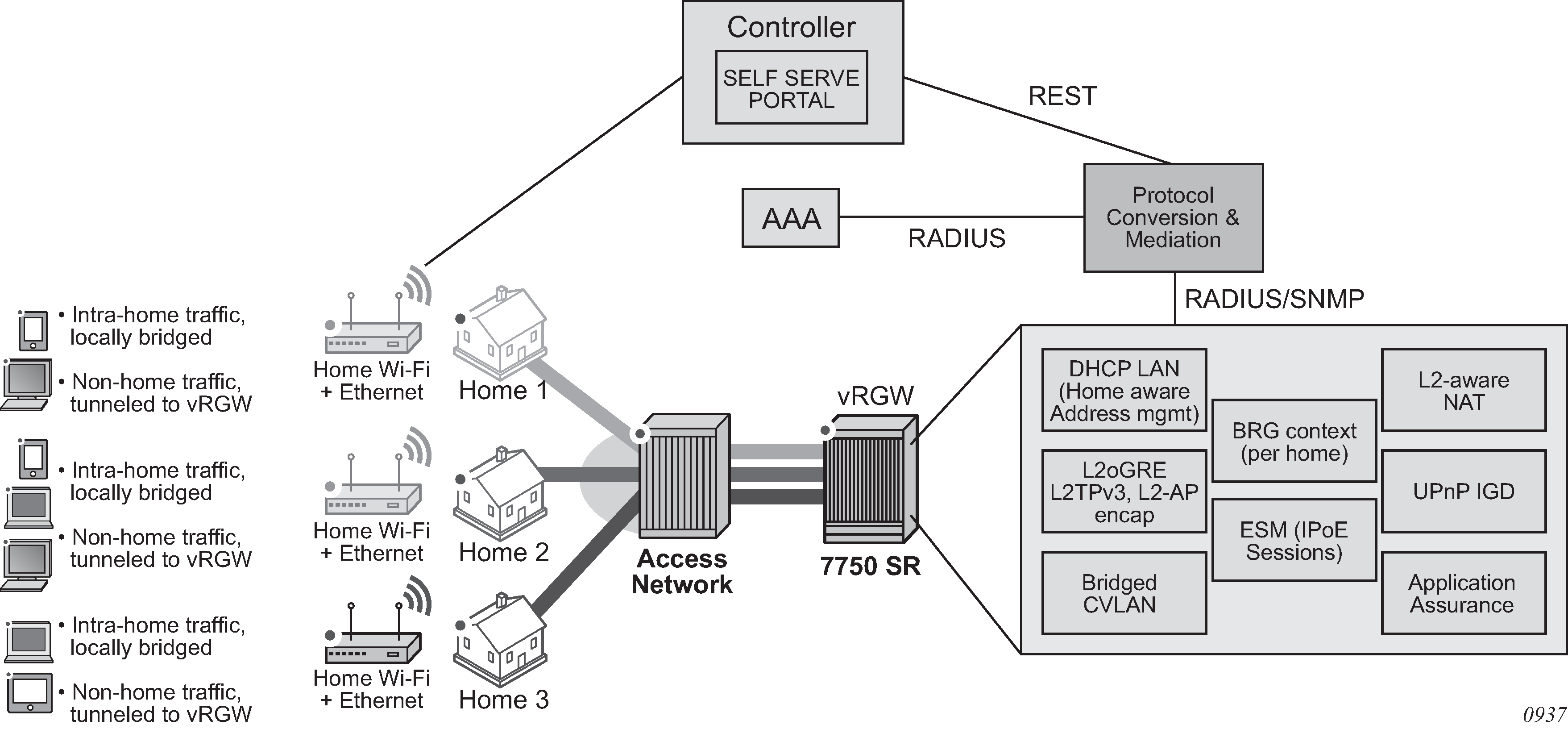
A Virtualized Residential Gateway (vRGW) transforms the Layer 3 routed Residential Gateway (RGW) in the home into a Bridged Residential Gateway (BRG), by moving the Layer 3 functions of an RGW into the network resides on a node (vRGW). The Layer 3 functionalities (such as address management, routing, Internet connectivity, NAT, UPnP, firewall, and application awareness) provides functions such as URL filtering and parental control and is moved to the network and resides on the vRGW. The RGW then operates in a bridged mode and performs local switching of intra-home traffic that originates and terminates on devices within the home. Bridged traffic destined for outside the home (such as to the Internet, the provider’s content, or another home) over the WAN toward the vRGW is hereby referred to as a BRG.
This mode of operation allows an operator visibility of the connected devices on the home LAN, instead of just a single IP address per home as is the case for a Layer 3 RGW. This allows operational improvements through per-device control and troubleshooting, and the ability to offer new services faster and on a more granular device specific-basis.
The router, as a dedicated gateway or as a BNG, serves as a vRGW providing Layer 3 termination and ESM functionality for bridged homes, as shown in Virtualized Residential Gateway (vRGW).
Access modes
All vRGW functionality is supported on both regular group interfaces (SAPs, LAGs, PW-SAPs, and so on) and WLAN-GW group interfaces (soft-GRE, soft-L2TPv3, VLAN).
A new configuration sub-node for the BRG is provided under the group-interface context for regular group interfaces and under the vlan-range context for WLAN-GW group interfaces. A regular group interface with a BRG sub-node does not support any non-BRG configuration and must operate in the ipoe-bridged mode.
In a WLAN-GW group interface, the BRG is configured in the vlan-range level. With a vlan-range it is not possible to mix BRG and other existing functionalities, but it is possible to mix BRG and other functionalities (such as WLAN-GW) on the same group interface. If a BRG also supports public WIFI, the expectation is that the BRG has different SSIDs for public WIFI and for private home traffic on the BRG, each represented by a different VLAN tag.
Contrary to WLAN-GW UEs, which require anchoring based on their MAC addresses (for mobility), devices associated with a BRG are anchored based on the tunnel source IP address of the BRG. The system therefore load-balances on a per-BRG granularity basis across a set of configured ISAs. Anchoring based on the source IP address of the BRG allows all devices in the home to be anchored on the same ISA and IOM. This enables aggregate QoS functionality within a single home.
Tunnel QoS is not supported as this is performed by regular subscriber QoS in the BRG scenario. WLAN-GW IOM (N:M) redundancy is supported. Data-triggered authentication (IPv4 only) is supported. All WLAN-GW access types (GRE, L2TPv3, L2-AP) are supported.
Home context on the vRGW
The system keeps a management context for each connected home or BRG, which is identified by a BRG ID. This context is used for authentication, configuration, and retrieval of operational data. Authentication can be performed explicitly by the BRG, in which case the vRGW acts as a RADIUS proxy. Alternatively, the vRGW can implicitly authenticate on the BRG’s behalf when the first host from the BRG connects.
Initial configuration parameters are provided as RADIUS attributes during authentication. Configuration parameters provided on the home level is used as defaults on the host level can be overridden on a per-host basis. Home-level configuration can be dynamically overridden by means of a RADIUS CoA message. See the ‟Virtual Residential Gateway” section in the 7450 ESS, 7750 SR, and VSR RADIUS Attributes Reference Guide.
Operational data provides information about the BRG, such as the number of connected devices, how long the BRG has been active, and which configuration parameters were provided. This can be retrieved via MIBs or show commands.
The vRGW communicates with a classic AAA server mainly to perform the authentication and with a separate configuration or operational platform. This separate configuration/operational platform is referred to as a ‟controller” and can be combined in a single management control system.
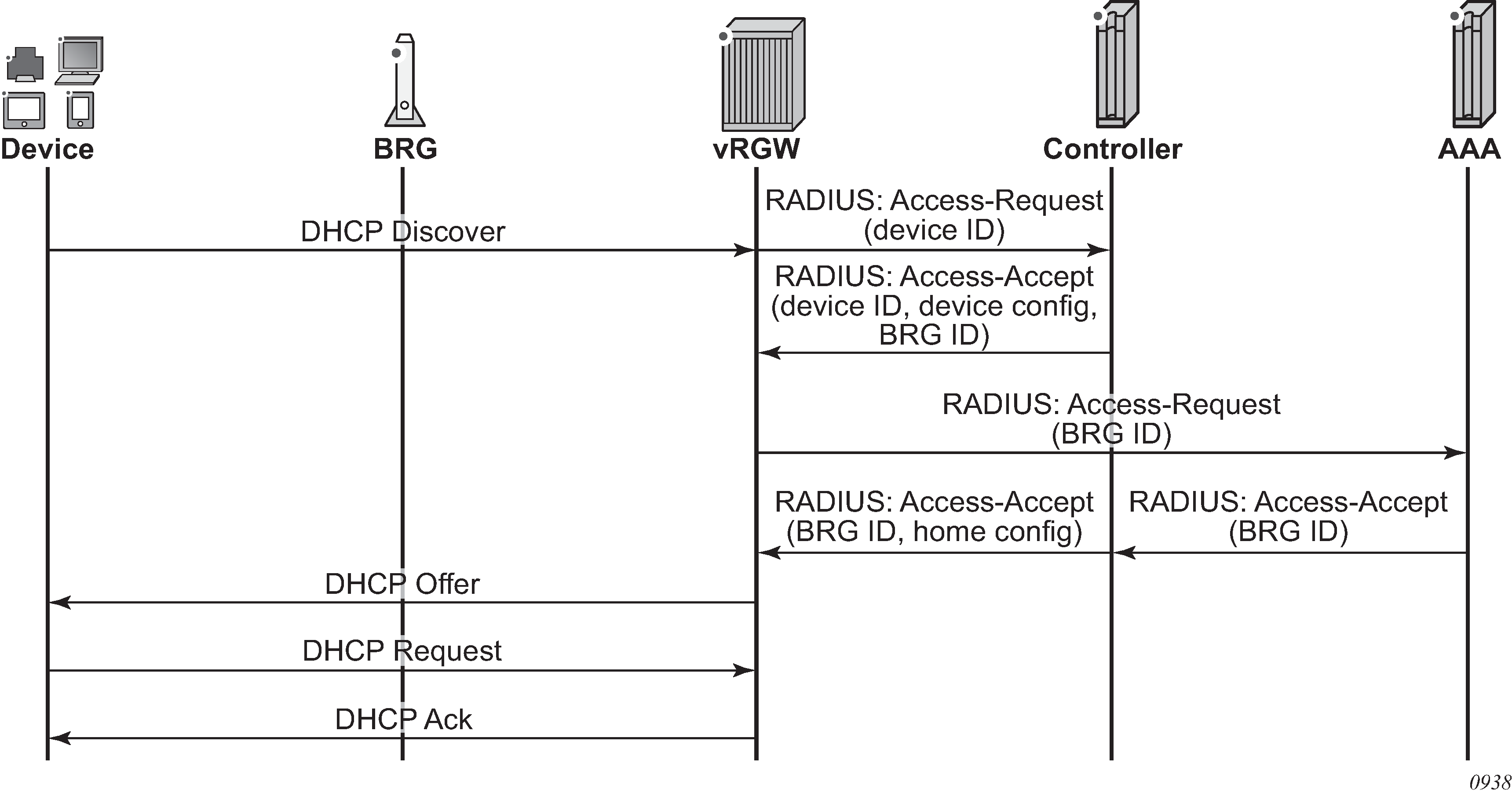
Implicit home authentication
With implicit home authentication (see Implicit home authentication ), the vRGW authenticates a new BRG when the first associated device connects. To avoid restrictions on the connectivity model, the vRGW initially attempts to identify a BRG with a BRG ID. The vRGW always performs authentication of a new host, and this authentication should return the BRG ID with which this host is associated. If this BRG ID is not yet known, the vRGW triggers BRG-level authentication. This allows an operator flexibility to identify a home. For example, one deployment may use CVLANs as an identifier while another may use a BRG MAC as an identifier.
When using the BRG MAC, this can be learned using the same methods as the AP MAC for WLAN-GW, as described in WIFI Aggregation and Offload, Authentication. The learned MAC can subsequently be reflected in authentication of the new device and mapped to a suitable BRG-ID by the AAA server or controller.
While a home can be optionally authenticated with an AAA server, each device in the home, is typically only authorized with a controller (via regular RADIUS messages and configured authentication policy) to get its configuration. This authorization is handled by the controller, which identifies and returns the associated BRG ID and, optionally, any device-level configuration.
Per-home authentication is forwarded to the AAA server to be fully authenticated. In this case, the controller typically performs an AAA proxy functionality so it can insert home configuration data in the final Access-Accept message. After both the device and BRG authentication are completed, the resulting RADIUS attributes are used to set up all required ESM objects (hosts, subscribers, SLA profile instances, filters, and so on).
Explicit home authentication
With explicit home authentication (see Explicit home authentication ), the BRG authenticates itself at boot time before allowing connectivity of any devices. The vRGW acts as a proxy for this authentication, and upon receipt of a successful authentication, the BRG context is created and stores all home parameters. As with implicit authentication, the vRGW performs authentication for each device and expects the BRG ID as a result.
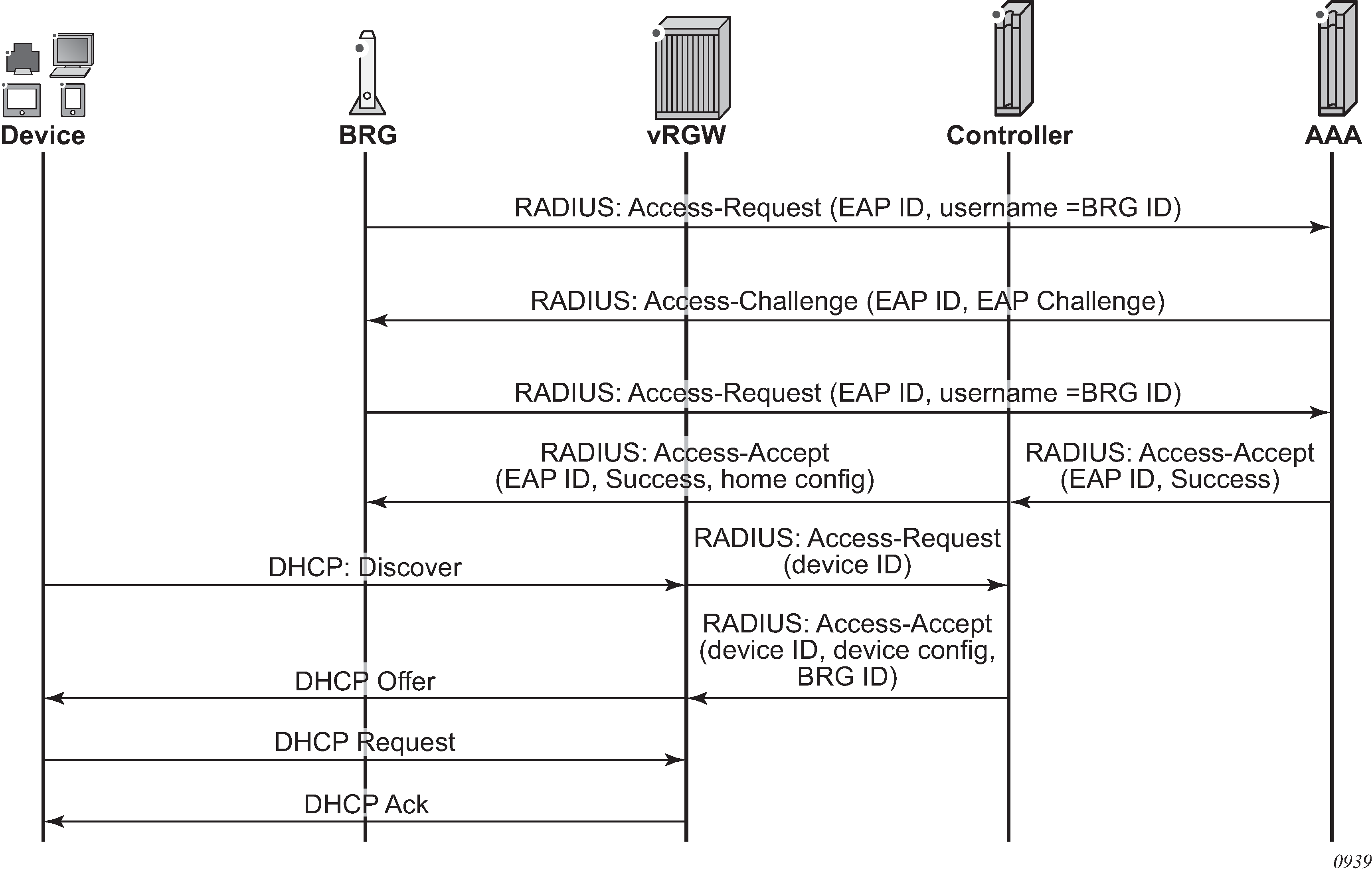
On the router, this functionality is obtained by including a RADIUS proxy in the vRGW configuration. This RADIUS proxy can be used for both WLAN-GW and vRGW scenarios and determines the difference based on the presence of a BRG ID attribute in the Access-Accept message. Proxy transactions in the context of a BRG are not cached. Instead, a fully functional BRG context is already created. Track accounting is not supported in the context of a BRG. Re-authentication is supported and behaves the same as on a CoA at the BRG level.
Change of configuration
RADIUS CoA can be used to change the configuration on a home level. The CoA can use the BRG ID as a key and contain attributes for all new or updated parameters. For all correctly specified parameters, the vRGW overwrites the existing configuration on the home level and updates all devices connected to the BRG.
Home lifetime
A configurable ping based on a smart connectivity-verification mechanism is provided to detect whether a BRG is alive. The BRG state is removed if it is not deemed alive (subject to a configurable hold time). A BRG is always considered to be alive if there are connected non-static devices. Static devices are not considered because there is no control plane to track whether they are alive. When no sessions are present, the home context can be in one of the following conditions.
On explicit authentication, where there is no session connection, the BRG state should be kept alive. To control this, an initial hold time applies during which the BRG context cannot be removed. Any connected device cancels the timer. If the timer expires and there are still no connections present, the BRG fall backs to the behavior as if the last session was removed.
-
If the last session was removed and connectivity verification is configured, the vRGW tries to ping the BRG. This ping mechanism uses ICMP or ICMPv6 ping toward the tunnel source IP or, if not present, toward the RADIUS source IP address. If the pinging is successful, the BRG context is kept. If the pinging is unsuccessful or impossible to perform (for example, if no IP address is known), the BRG falls back to the hold time. If, during the connectivity verification, a host connects to the BRG, the verification is stopped and the BRG is assumed to be alive again.
-
If the last session was removed and connectivity verification failed or was not configured, a configurable hold time applies, during which time the BRG is not removed. If a new device connects during a hold time, the timer is canceled. If the timer is not canceled, the BRG is removed when the timer expires. The configured hold time can be zero and can be different from the initial hold time.
Device context on the vRGW
The router maps every device in a home to an IPoE session, which can contain one or more ESM hosts, depending on the number of IP stacks active on the device. The vRGW authorizes every single device and stores the resulting configuration data with the IPoE session. Whenever the session is created or updated, the vRGW combines the configuration data of the home context with the configuration data of the device. When the same configuration object is present on both levels, the device level applies. The resulting combined configuration data is used to install or update the ESM objects.
Dynamic configuration changes
Use a RADIUS CoA to dynamically change the configuration on both the home level and the device level. Use the BRG ID as the key on the CoA on the home level. The included attributes overwrites the existing stored configuration on the home level and subsequently update all devices connected to the home. All devices pick up the new home-level configuration unless a more specific configuration exists on the device level.
A CoA on the device level can use all existing ESM keys as detailed in the 7450 ESS, 7750 SR, and VSR RADIUS Attributes Reference Guide. The keys update the existing configuration on the device level. If the device inherits the specified parameter from the home level, this parameter is updated on the device level; the existing home-level configuration remains intact and is used as the default for other devices.
In specific cases, the configuration can be removed on the device level to be able to fall back to the home level, supported by the RADIUS attribute Alc-Remove-Override. This attribute lists which overrides must be removed on the session level and fall back (revert) to the home-level configuration. If the home parameter changes, the device also picks up the new configuration.
For more information about RADIUS configuration attributes, see the 7450 ESS, 7750 SR, and VSR RADIUS Attributes Reference Guide.
Per-home pool management and L2-Aware NAT
This feature allows the provisioning of a DHCP pool per home in a vRGW context. The addresses in a per-home pool are unique, so local bridging can occur within the home functions. Devices in different homes can, however, be allocated the same address. L2-Aware NAT is then used to handle address translation and connectivity toward the network and between homes. Per-home default gateway, subnet, and address range (out of which addresses are allocated to home devices) can be configured via the CLI. The address range can be overridden from RADIUS. The subnet associated with the home pool must be within the configured L2-Aware inside subnet. L2-Aware source NAT can optionally be combined with destination NAT to support enhanced traffic redirection (such as for stateful DNS overwrite function). More details on network address translation forwarding can be found in the 7450 ESS, 7750 SR, and VSR Multiservice ISA and ESA Guide. In addition to the IPv4 addresses from the home pool, the following hosts can be set up:
IPv4 DHCP proxy hosts using an AAA-provisioned address
Only non L2-Aware hosts can receive a framed IP address from RADIUS.
-
IPv6 SLAAC hosts using an AAA-provisioned address or a local address assignment
-
IPv6 IA_NA hosts using DHCPv6 relay, an AAA-provisioned address, or a local address assignment
Sticky IP addresses
The vRGW can be programmed with a list of sticky IP addresses per BRG. A sticky IP address is an IPv4 address from the home pool allocation range that is set aside for a specific device based on the MAC address and is never allocated to any other device. This can be used for devices where a persistent IP address is desirable but configuring a static IP address on the device is too cumbersome (such as a network printer). The device still uses DHCP to gain connectivity but is always assigned the same IP address.Public (non-NAT) sticky IP addresses are not directly supported in pool management but can be provisioned in the following manner.
Create a local DHCP server and pool to manage the public address space.
For each public sticky IP address that must be provisioned, create a sticky lease in this pool. See DHCP Address Reservation for Sticky Leases for further details. Both the user identification and hostname can be the MAC address of the associated device.
When the device linked to the sticky lease authorizes with the controller, it returns the allocated address as a framed IP address. This address takes precedence over any home pool configuration and a DHCP proxy host is installed.
Managed static IPv4 addresses
Like sticky IP addresses, the vRGW can be programmed with a list of static IP addresses per BRG. However, for static IP addresses, DHCP is not expected from clients and is dropped. The vRGW automatically installs all the addresses as IPv4 hosts contained in IPoE sessions. Because every host must be linked to a specific point of access (such as a SAP or tunnel) the vRGW needs to wait on a data trigger or the first non-static host in a home before static hosts can be created. Like regular (DHCP-triggered) hosts, a device-level authorization is performed for each static host to retrieve the per-device level configuration. This type of static host can cover both private (inside the home subnet) and public (non-L2-Aware NAT) addresses. The created hosts can only be explicitly removed by the management interface, and mechanisms such as session-timeout and idle-timeout are not supported.
DMZ
A single DMZ address can be provisioned per home via RADIUS (VSA Alc-DMZ-Address), which can be any address inside the home subnet except for the default gateway. When a host exists with this address, the DMZ mode is activated. DMZ is be activated if a host exists with the address and the subscriber uses only one port range per IP. Without DMZ mode enabled, any traffic arriving for the NAT outside IP that does not match an existing flow, pinhole, or port-forward, is dropped. With DMZ mode enabled, this traffic is forwarded to the provisioned DMZ host.
IPv6
The vRGW supports the following IPv6 host types:
IPv6 SLAAC hosts using an AAA-provisioned address or a local address assignment
IPv6 IA_NA hosts using DHCPv6 relay, an AAA-provisioned address, or a local address assignment
The vRGW only operates in IPoE bridge mode. For regular group interfaces, the IPoE bridge mode must be explicitly enabled before the BRG can be enabled. For WLAN-GW group interfaces, the IPoE bridge mode is implicitly assumed for a VLAN with BRG enabled. This has the following consequences:
-
SLAAC hosts from the same home can share a /64 prefix
-
when a local address assignment is used, SLAAC hosts from the same home are automatically assigned the same /64 prefix
-
IA_NA hosts from the same BRG can receive unique addresses from a shared /64 prefix. This prefix is automatically signaled in an RA
QoS and filter support
The vRGW is based on existing ESM QoS configurations on the router where each home maps to a single subscriber instance. Home-level bandwidth can be provided by an aggregate rate or scheduler policy on the subscriber level. Groups of home devices (such as telephones, computers, televisions, and security systems) can be given a shared bandwidth by assigning a different SLA profile per such group. Individual device-level QoS can be provisioned by mapping a specific device to a specific forwarding class using IP classifiers based on the device IP. This forwarding class can then be mapped to its own individual queue. Dynamic QoS overrides can be provisioned on both the home level and the device level. While QoS overrides are represented by a single RADIUS attribute, the device level does not override the whole attribute but only the QoS objects specified on that level. For example, on the home level, the scheduler bandwidth is overridden, and on the device level, queue bandwidth is overridden. The resulting override is a combination of both.
Data-triggered authentication
ISA-based IPv4 data-triggered authentication (Data-triggered authentication ) and host creation is supported on WLAN-GW group interfaces. When authenticating a data-triggered device, connection data provides less data for the controller to derive the BRG, unlike DHCP where the BRG can insert its identifier, such as a circuit ID. For pure Layer 2 access, a BRG ID can be hard-coded to a port and VLANs, although for tunneled access, this is not always possible as the corresponding value would be the tunnel source IP address. This IP address can be dynamically assigned and changed with a BRG reboot. The following alternatives are suggested.
Use AP MAC as the identifier. This identifier can be signaled in DHCP and DHCPv6 as specified in WIFI Aggregation and Offload. For data-trigger purposes, it can also be sent as part of the L2TPv3 header, or if a GRE, it can be learned upon data-trigger via an ARPoGRE/NDoGRE message.
-
Use a custom identifier that is sent in DHCP in a circuit ID option or a vendor-specific option. To handle the data trigger while a DHCP lease is active, a controller keeps its state to map the device MAC to the BRG identifier.
-
If it the data trigger was for a static IP address (for example, when the static device is the first to send upstream data in the home), the triggering static host and any other provisioned static hosts are installed.
If the data-triggered device is the first device to come up in the home and the BRG did not perform explicit authentication, the vRGW also triggers an implicit authentication. After authentication, the data-triggered host can be installed by one of the following methods.
-
If the trigger was sent for a dynamic host (sticky/not sticky), (for example, when connection with a device was lost (based on an idle-timeout) but the lease was still valid), a DHCP lease is re-created using the provisioned lease time on the home level. This installed lease time is usually excessive compared to the actual remaining lease time on the device, but this is corrected when the lease performs DHCP renew or rebind procedures.
The actual remaining lease time is used if known. If a host goes idle and sends a data trigger, the actual remaining lease time is used.

Per-host NAT port ranges
Carriers want to offer opt-in value-added services (VAS) through dedicated DPI-based appliances or VMs in data centers. This functionality requires vRGW support to forward traffic (ideally, only for subscribers who have subscribed to the VAS) to the external appliance. The appliance implements per-subscriber and per-device policies, and must be able to determine the subscriber and device from the received packets. Because address space across homes can overlap, subscriber-aware NAT is a requirement in the vRGW architecture. When subscriber-aware NAT is used, the outside IP address is unique and corresponds to the subscriber but, by default, the device information is lost. However, the device can be determined for the external appliance from the Layer 3 packet if a unique NAT outside port range is used per device on the vRGW.
By default, the subscriber-aware NAT allows the entire port range (other than the port range for static port forwarding) to be available for dynamic NAT flows and dynamic port forwarding (via UPnP). The feature adds support for allocating per-host NAT outside port ranges, and reporting per-host port-range allocation and deallocation in RADIUS accounting. External VAS appliances can then track RADIUS accounting to determine device to port-range mapping.
The port range for a host is allocated and deallocated when the host is created and deleted, respectively. A single port range per host is supported. The RADIUS attribute Alc-Per-Host-Port-Range provides the count of ports per host for a subscriber. See the 7450 ESS, 7750 SR, and VSR RADIUS Attributes Reference Guide for information about the attribute format. In case of multiple NAT policies per subscriber, the attribute value is required to be the same for all policies.
The presence of the VSA implicitly enables the per-host NAT port-range allocation mode. The ports-per-host mode is only enabled (via the VSA) if vRGW is enabled (as indicated by the presence of BRG in no shutdown) under the VLAN range on the WLAN-GW interface, or on the group interface. The VSA can be present in access-accept for BRG authentication (implicit or explicit), and in CoA (with Alc-BRG-Id as the key). If a CoA is received with the Alc-Per-Host-Port-Range set to 0, it indicates the disabling of the per-host port-range mode.
If the Alc-Per-Host-Port-Range VSA is changed, the flows in the overlapping region between the new and old port ranges remain intact; any remaining flows are removed.
When the ports-per-host mode is disabled (via the VSA), the new port range includes all ports except the SPFs, and in accordance with the preceding rule, no ports are deleted.
When ports-per-host mode is enabled mid-session (via the VSA), the new port range falls within the old port range, where the old range contained all ports except the SPFs.
The ISA is updated from the CPM for all hosts when the ports-per-host mode changes, and cleanup occurs in accordance with the preceding rule.
The per-host port-range is included in the Alc-Nat-Port-Range attribute in per-host or per-session RADIUS accounting (in accordance with the currently supported format of the Alc-Nat-Port-Range VSA for L2-Aware NATs).
When a new port block for a host is allocated or freed, an interim-update message with a Nat-Port-Range-Event reason is sent. The interim update is sent only when interim updates are enabled and the configured include-attributes contain the alc-port-range VSA.
The port range for a host remains allocated for the lifetime of the host (unless explicitly removed using the VSA). Per-host reserved ports (for prioritized sessions) and watermarks to indicate exhaustion of per-host port-range are not supported.
Inter-chassis redundancy
vRGW supports stateless inter-chassis redundancy, where the home and device state is not explicitly synchronized between the two vRGWs. After a redundancy switchover event, Data Triggered Authentication (DTA) is used to download the correct home and device state back from the controller. The controller should always have the latest configuration state of a specific home, including any overrides after the home was activated. Additionally, the controller maintains a minimal state for DHCP pool management that can be reflected to the vRGW in case of a redundancy event, as shown in Inter-chassis redundancy.
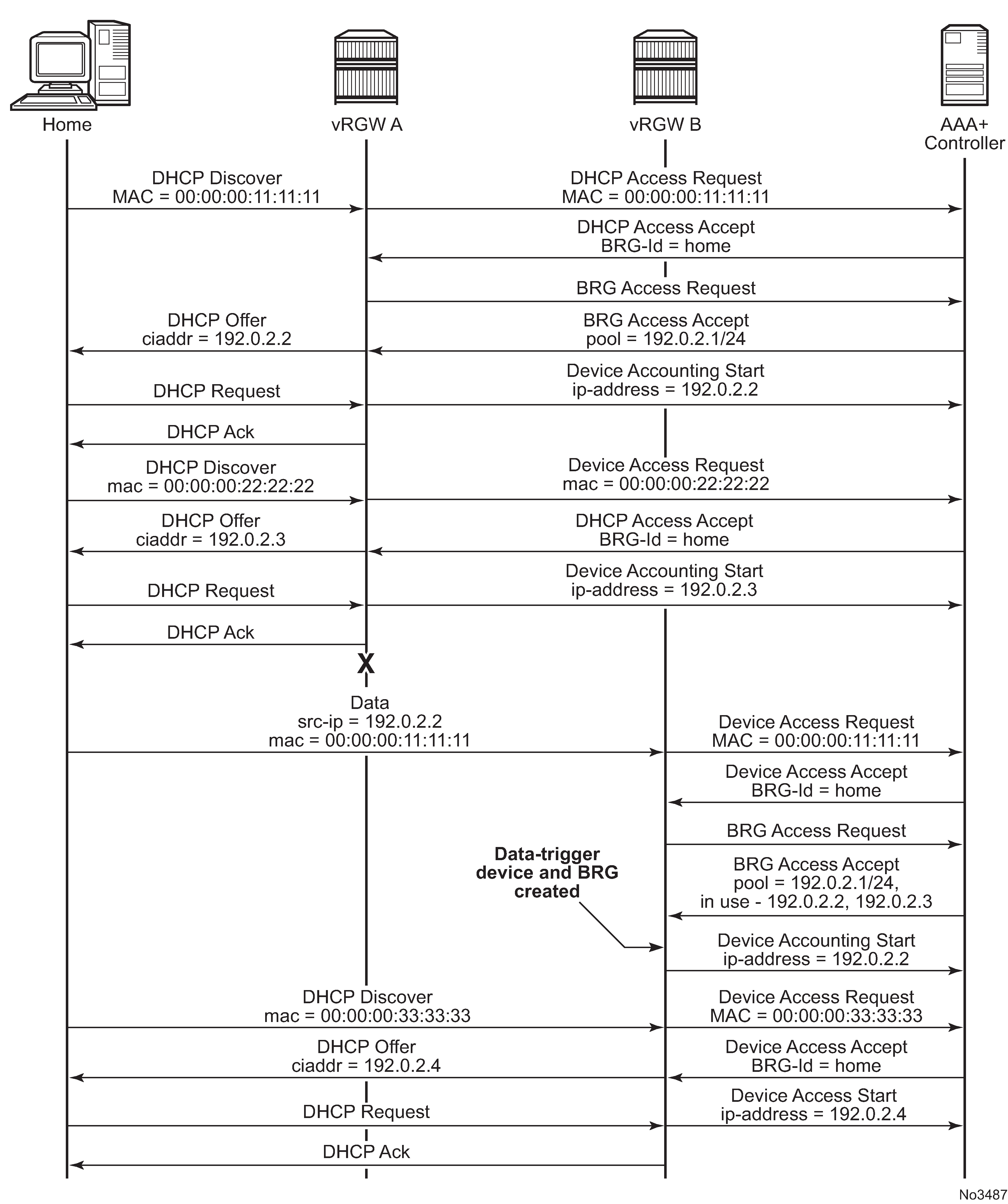
Pool state synchronization
Because there is no stateful synchronization between pairs of redundant gateways, all pool state information is lost in a switchover event. The new gateway creates a new pool with state information for all configured reserved and static address, but has no information about dynamic addresses. When a data-triggered host is authenticated, the pool tries to recreate the lease corresponding with this source IP address. However, this is subject to race conditions. If a data trigger is delayed (for example, the device is not active upon switchover) the DHCP pool may already have assigned the IP address to a new device in the home. This not only blocks the data-trigger for the old device, but may lead to address duplication issues inside the home. To solve this issue, the controller keeps track of allocated dynamic IP addresses. After a switchover event, these addresses can be sent to the vRGW as part of the BRG configuration. In this case, the per-home pool only allocates these addresses to data-triggered devices or DHCP renew triggered devices that request this specific IP address. New devices receive addresses not present on this list. After a configurable timeout, the pool relinquishes any unclaimed IP addresses back to the pool for general use. The currently unclaimed addresses can be displayed using the following command.
show subscriber-mgmt brg gateway brg-id "00:00:5e:00:53:05" standby-ip-addresses
===============================================================================
Bridged Residential Gateway home-aware pool standby IP addresses
===============================================================================
Home-aware pool : 00:00:5e:00:53:05
-------------------------------------------------------------------------------
192.0.2.10
192.0.2.11
192.0.2.12
-------------------------------------------------------------------------------
No. of standby IP addresses: 3
===============================================================================
It is recommended to keep the pool state on the controller basic, by marking an address as used when a device is connected and unused when it is disconnected. Periodically, explicitly synchronize the controller with the vRGW to remove addresses for which a device disconnect notification may have been lost.
Regular group interfaces
On regular group interfaces, redundancy is supported by enabling SRRP and IPoE session stateless redundancy. For more information about stateless redundancy, see Stateful Multi-Chassis Redundancy (MCS). The backup router is always in the backup-routing mode. There is no support for shunting traffic via a redundant interface from the standby to the active router.
IPv6 traffic and public IPv4 is attracted to the correct active (SRRP master state) router by the regular track-SRRP mechanism. L2-Aware NAT outside pools cannot use track-SRRP and should be configured distinctly on both routers making up the redundant pair. After a redundancy event, each home gains a new outside IP address on the new active router.
BRGs send out Gratuitous ARP (GARP) messages, which direct traffic to the correct active router. These GARPs update the FDB of the dual-homed Layer 2 aggregation nodes. GARPs are not supported for L2-Aware inside prefixes. At least one subscriber interface subnet must be explicitly configured to send a GARP.
When using MSAP deployments, the managed SAPs are not synchronized and must be recreated on the new active router via data-triggered authentication. Because there are no managed SAPs present, no GARPs can be sent when a standby router becomes active. If the aggregation node has a shared FDB for all C-VLANs (FDB per S-VLAN) or for all S-VLANs (FDB per switch), it is recommended to configure a single static SAP per S-VLAN or per port over which a single ARP can be sent.
WLAN-GW group interfaces
Redundancy on WLAN-GW group interfaces reuses the WLAN-GW monitor route mechanism to determine the active or standby state of each router in a pair of redundant routers. For more information see WLAN-GW 1:1 Active-Backup Redundancy. When using the BRG MAC as a BRG identifier, an ARPoGRE (IPv4 GRE tunnel) or NDoGRE (IPv6 GRE tunnel) is triggered when receiving a data-trigger for an unknown device. Authentication of the data trigger is delayed until the ARP/ND is answered or timed out.
config>service>vprn>sub-if>grp-if>wlan-gw
        learn-ap-mac delay-auth
IPv6 and public IPv4 traffic from the network is attracted to the active router because a subscriber interface on a standby router is operationally disabled and its associated subnets are not exported to the route table. L2-Aware NAT outside pools stay active on both routers and should be configured independently on both routers, making up the redundant pair. After a redundancy event, each home gains a new outside IP address on the new active router.
Traffic from the BRG is directed by regular routing, as only the active router exports the configured tunnel endpoints.
Access via the Layer 2 access point is not supported in a redundant setup.
Alternatively, vRGW with tunnel access also supports active and active redundancy using two different tunnel endpoint addresses. In this setup, each vRGW acts independently and does not synchronize any state. Each BRG is responsible for determining which vRGW is considered active; for example, by sending ICMP/ICMP6 echo requests toward the tunnel endpoints. After detecting a failover, the BRG is direct traffic toward the alternate tunnel endpoint. The state on this vRGW is re-created using the data triggers. This is like the monitor-route active or backup redundancy as discussed in WLAN-GW group interfaces. Explicit BRG authentication is supported in this use case if the BRG keeps track of a pair of tunnel endpoints and RADIUS server (proxy) addresses.
Redundancy of public IPv4 addresses and IPv6 addresses is not supported with an active/active deployment. After a failover event, it is not possible to send traffic for these addresses until the BRG restores connectivity to its original vRGW.
BRG and vRG restrictions
Static IPv6 hosts are not supported in vRGW. It is possible to provide a static IPv4 host with a SLAAC prefix and use IPoE linking to automatically create an associated IPv6 host.
-
Wholesale/retail is not supported in vRGW.
-
Subnets provisioned for BRG pool management must lie in a pre-configured L2-Aware NAT inside prefix. The dynamic range of a BRG pool must not contain the configured L2-Aware NAT inside IP address.
-
BRG connectivity verification is limited to a maximum of 50,000 BRGs. If more BRGs are connected, connectivity verification is performed for the excess numbers and only hold-time applies before the BRG instance is deleted from the vRGW.
-
On regular group interfaces, only a single BRG is supported per SAP.
-
There is a maximum of one SLAAC prefix per BRG.
-
There is a maximum of 128 IPoE sessions per BRG, and a maximum of 8 static hosts per BRG.
-
The idle timeout is based on SLA profile instance, not per host. For hosts under the same BRG sharing an SLA profile, it is not possible to detect early disconnect of a single host.
-
All SLAAC hosts under a BRG sharing the same prefix uses a common forwarding context downstream. For predictable behavior, the same SLA profile should be used for each SLAAC host.
External allocation of L2-Aware NAT outside IP addresses
Certain residential deployments use multiple NAT outside IP addresses on routed physical raw (unknown encapsulation) packets, typically one per service. This feature provides similar support for multiple NAT outside IP addresses (up to four) per BRG (in other words, per subscriber) on vRGW. These addresses fall within locally-defined NAT pools on vRGW, but are assigned and managed by an external backend system. Each NAT outside IP address typically corresponds to a service, for instance, an HSI service may be NAT’ed to a different outside IP address than the voice service.
The NAT outside IP address and the corresponding NAT policy associated with the subscriber is provided by a VSA (Alc-Nat-Outside-IPs) in the RADIUS access-accept message or the CoA. Up to four instances of this VSA can be included in the RADIUS access-accept message or the CoA, which provides multiple NAT outside IP addresses for a BRG. The NAT pool referred to within the NAT policy must be configured for external assignment. If the provided outside IP address in the VSA does not fall in the NAT pool referenced within the corresponding NAT policy, then the outside IP address (and the mapping) is ignored. If the outside IP address falls within the NAT pool, and is not already allocated, then it is assigned to the L2-Aware subscriber. If the NAT policy contained in the VSA refers to a NAT pool that is not configured for external assignment, then the host setup fails. The external system is responsible for ensuring the stickiness of the outside IP addresses for the subscriber, if needed.
The system internally chooses an ISA in the NAT group to anchor an L2-Aware subscriber, such as the ISA, to where the NAT flows for the subscriber are created, based on upstream data or static port forwards. If a NAT outside IP address does not fall within the address block owned by the NAT ISA that anchors the L2-Aware subscriber, then the NAT outside IP address (/32) is added to the FDB with the ISA as the next hop. Otherwise, the downstream traffic forwarding to the NAT ISA for the L2-Aware subscriber follows the aggregate route corresponding to the address block owned by the NAT ISA.
The NAT outside IP address to use for a flow on the NAT ISA is based on a destination IP address lookup in a nat-prefix-list specified in the sub-profile for the subscriber. The nat-prefix-list contains a list of IP prefixes to NAT-policy mappings. The destination IP lookup in the nat-prefix-list provides the NAT policy to use. The NAT outside IP address that is associated with this NAT-policy is then used as the translated source IP.
config>service
     nat
       nat-policy "nat-policy-voice" create
           pool "voice-pool" router 401
       exit
       nat-prefix-list "nat-prefix-list-voice" application l2-aware-dest-to-policy create
           prefix 203.0.113.235/16 nat-policy "nat-policy-voice"
       exit
     exit
config>subscr-mgmt
        sub-profile "sub-prof-hsi-voice" create
            nat-policy "default-policy"
            nat-prefix-list "nat-prefix-list-voice"
        exit
config>service>vprn>nat>outside
    pool "voice-pool" nat-group 1 type l2-aware create
    port-reservation blocks 1
    external-assignment
    exit
To add a new NAT outside IP address for a subscriber by CoA, AAA must provide updated NAT outside IP-to-nat-policy mappings. AAA associates the correct sub-profile (containing the nat-prefix-list to map a destination IP prefix with the NAT policy that contains the new NAT outside IP address) with the subscriber; that is, the sub-profile associated with the subscriber needs to be changed using CoA. The CoA must always contain all the <NAT outside IP to-nat-policy> mappings associated with the subscriber (because it is cumulative). When the entire port range is available to the subscriber, the port-reservation blocks num-blocks command should be configured as 1 if external-assignment is enabled on the NAT pool.
All associated NAT outside IP addresses and corresponding NAT policies can be displayed via the show service nat l2-aware-subscribers command.
A:Dut-A# show service nat l2-aware-subscribers
===============================================================================
Layer-2-Aware NAT subscribers
===============================================================================
Subscriber                            : sub-2-4-ext
-------------------------------------------------------------------------------
ISA NAT group                         : 1
ISA NAT group member                  : 1
UPnP policy                           : (None)
Default NAT policy                    : nat-policy-hsi
Per-host port block size              : N/A
Firewall policy                       : (None)

Policy                                : nat-policy-hsi
Purpose                               : nat
Outside router                        : vprn100
Outside IP                            : 198.51.100.235
DNAT default IP address override      : (Not Specified)
DNAT disabled by override             : false
Ports                                 : 1024-5119

Policy                                : nat-policy-voice
Purpose                               : nat
Outside router                        : vprn100
Outside IP                            : 198.51.100.245
DNAT default IP address override      : (Not Specified)
DNAT disabled by override             : false
Ports                                 : 1024-5119

-------------------------------------------------------------------------------
No. of subscribers: 1
The nat pool show command output shows the attribute that controls external assignment.
show router 70 nat pool "vprn l2aw"
===============================================================================
NAT Pool vprn l2aw
===============================================================================
Description                           : (Not Specified)
ISA NAT Group                         : 4
Pool type                             : l2Aware
Applications                          : (None)
Admin state                           : outOfService
Mode                                  : auto (napt)
Port forwarding dyn blocks reserved   : 0
Port forwarding range                 : 1 - 1023
Port reservation                      : 128 blocks
Block usage High Watermark (%)        : (Not Specified)
Block usage Low Watermark (%)         : (Not Specified)
Block usage (%)                       : < 1
External assignment                   : true
Last Mgmt Change                      : 05/17/2016 13:41:04
===============================================================================
PPPoE client
The vRGW allows operators to start a PPPoE client per BRG to a remote BNG. This PPPoE client forwards traffic that goes through NAT or firewall. The NAT-outside IP address and SLAAC prefix used are negotiated via the PPPoE client.
The PPPoE client runs directly on the ISA and encapsulates packets directly after NAT or firewall functionality. Encapsulated packets are sent out over an Epipe that is directly linked to the NAT group during configuration. Multiple clients can share a single Epipe if they have unique MAC addresses. Clients are automatically hashed over multiple ISAs in the NAT-group. By default, hashing is based on source and destination MAC; however, if many Epipes are being used and there is a high reuse of MAC addresses, Epipes should be configured to use per-service hashing instead.
A vRGW with PPPoE client enabled can still support routed hosts outside NAT or firewall.
PPPoE client setup
PPPoE client setup is triggered when a BRG is created with any PPPoE parameter provided during authentication. At least one PPPoE Epipe service ID and one PPPoE client policy name must be provided. A MAC address for the client should also be provided, but, if absent, the system attempts to parse the BRG ID as a MAC address. An optional service name can be configured that are reflected in PPPoE setup. LCP keepalives are defined in the PPPoE client policy. The client supports either no authentication, PAP, or CHAP. The username and password can be transmitted as parameters during BRG authentication.
The PPPoE client allows negotiation of both IPCP and IPv6CP with SLAAC and, optionally, stateless DHCPv6. The negotiated IPv4 address is used as a NAT-outside address and is not signaled to the clients in the home. The received IPv6 SLAAC prefix is reused as a SLAAC prefix toward the home. The Preferred and Valid lifetimes signaled toward home are not synchronized with the values received with the BRAS, but are only subject to local configuration. DHCPv6 hosts in the home cannot be subject to the PPPoE client.
The BRG can use the PPPoE client for address assignments instead of traditional sources such as AAA, LAA, or NAT pool. PPPoE client is mutually exclusive to other address sources. The used NAT and firewall policies must be configured in l2-outside mode. DNS, DNSv6, and NBNS can be provided by both the PPPoE client (IPCP, RA, stateless DHCPv6) or by vRGW AAA. Nokia recommends operators do not mix sources, because there is no strict precedence and only the last update is kept.
Setup of the BRG and devices linked to the BRG is blocked until setup of the PPPoE client is complete. If, after a timeout (configurable in the BRG profile) the client does not completely come up, setup of the BRG and devices continues with the information available. This allows, for example, IPv4 to continue setup even if IPv6 negotiation fails.
Aside from the MAC and service ID, most PPPoE client parameters can be changed while BRG is operational. Changing any PPPoE parameters causes the PPPoE client to restart, which impacts data traffic in the same way as a PPPoE client failure.
Non-LCP PPPoE control plane packets are always sent within the NC forwarding class and dot1p 0. Egress remarking can be used to change dot1p values.
PPPoE client failure
If there is a partial failure of the PPPoE client, no BRG or in-home device states are removed. All affected stacks no longer forwards traffic and any flow states may be removed. Setup of IPv4 hosts and routed (non-PPPoE client) devices continues. Existing SLAAC hosts are not removed, but a deprecation RA (with 0 lifetimes) is sent and no new SLAAC hosts are created.
The PPPoE client attempts to re-establish the connection, subject to the configured retry and backoff timers. Traffic is allowed again after the connection is restored. If a new IPv4 address is assigned, this is immediately applied as the new NAT outside address. If a new IPv6 prefix is assigned, IPv6 prefix replacement is triggered for existing SLAAC hosts.
If the peer MAC address changes during a reconnection, it may be hashed to a different NAT ISA. This is not supported by the system, and if it occurs, the entire BRG is removed.
LCP keepalive
LCP keepalive intervals are configured in the PPPoE client policy. While the regular PPPoE control plane is initiated from the CPM, keepalives are handled directly on the ISA. Because the ISA is aware of any traffic, this handling is optimized so that echo requests are not sent if active traffic is received from the BRAS. The keepalive timer is reset upon each received echo-request. These two mechanisms significantly reduce PPP keepalive messages without compromising liveness detection. Incoming echo requests are always responded to, if LCP is in the LCP Opened state.
LCP PPPoE packets are always sent within the NC forwarding class and dot1p 7. Egress remarking can be used to change dot1p values.
MRU/MTU
Each PPPoE client policy allows configuration of both MRU and MTU. The MRU is sent toward the peer during the discovery phase. If any of the MRU or MTU is bigger than 1492, the Max-Payload tag is included and is set to the maximum of the configured MRU and MTU values.
Upstream data packets are subject to the smallest of either the received MRU or the configured MTU. The node fragments IPv4 packets without the DF flag set and drops IPv6 packets and IPv4 packets with the DF flag set. For the packets with the DF flag set, appropriate ICMP or ICMP v6 error messages are sent.
SLAAC prefix replacement
SLAAC prefix deprecation is supported with vRGW. Contrary to generic prefix replacement, vRGW uses radius attribute Framed-IPv6-Prefix to change the prefix in a BRG-level CoA or re-authentication. For PPPoE clients, prefix replacement is performed whenever the SLAAC prefix is signaled via PPPoE changes. See SLAAC for more information about SLAAC prefix deprecation.
When a SLAAC prefix is assigned to a BRG that previously had no prefix, an unsolicited RA is generated for all sessions currently active for that BRG. Data-triggered host creation should be enabled to allow subsequent setup of IPv6 hosts.
SLAAC prefix deprecation is supported for a PPPoE client. Whenever the state of the SLAAC prefix is lost, such as when a PPPoE client goes down, an RA with 0 lifetimes is sent out and no new SLAAC hosts can be set up. Existing hosts remain in the system but are no longer forwarded. When the same SLAAC prefix is reassigned, existing hosts begin forwarding traffic again.
Home LAN Extension
This section describes the Home LAN Extension (HLE) feature.
Overview
HLE allows an operator to extend the home network of the broadband user to a WAN network, such as a data center, by creating a per-home Bridge Domain (BD) on a Broadband Network Gateway (BNG). This feature provides the operator with the capability to deploy new services in a data center that have full Layer 2 reachability to the home and visibility to each individual host.
The per-home BD is created on a WLAN-GW ISA, and the system uses standard BGP EVPN VPLS services to extend the BD to remote networks.
Home LAN extension displays an example of an HLE configuration.

HLE requires the BNG to have Layer 2 access to the home network. The BNG supports the following types of access:
soft GRE or L2TPv3 tunnel from a home gateway, which encapsulates Ethernet traffic from the host into a GRE/L2TPv3 tunnel
native VLAN access that is terminated on the WLAN-GW group ISA using L2-AP access
A unique BD is created on the ISA for each home. The BD bridges traffic between the following connections:
access-facing connection (for example, home)
GRE/L2TPv3/L2-AP
network-facing connection (for example, DC)
BGP EVPN tunnel
ESM SAP-facing connection
each home has its own ESM SAP
Each BD has a unique ID, which is a number returned by the RADIUS server as the Alc-Bridge-Id attribute during home authentication.
With HLE services, each home host is a WLAN-GW UE object and an ESM host object. Each network host (such as a VM in a data center) is a WLAN-GW UE object but not a ESM host. This means that a network host cannot use the BNG as the default router for other non-home-facing traffic.
HLE relies on SR OS vRGW functions, which means that the vRGW BRG in the same VLAN range of the WLAN-GW group interface must be enabled for HLE.
Authentication and authorization
Because HLE relies on the vRGW, it is carried in conjunction with vRGW home authentication and supports both implicit and explicit vRGW home authentication. Enabling the HLE service for a specific home (ESM subscriber) is triggered by a RADIUS server that returns an Alc-Bridge-Id message during home authentication.
The Alc-Bridge-Id attribute must be returned in both home and session authentication. The returned value must be equal on both authentication levels.
The Alc-Bridge-Id is the ID of the per-subscriber BD on the ISA. It is different from the Alc-BRG-ID, which is the ID of the BRG.
In addition to the Alc-Bridge-Id, the following optional attributes can be returned during BRG authentication:
HLE BGP EVPN route target: Alc-RT
HLE BGP EVPN route distinguisher: Alc-RD
HLE BGP EVPN VXLAN VNI: Alc-Vxlan-VNI
Data plane tables
HLE is an essential Layer 2 bridge service. The data plane consists of a per- subscriber BD that contains the following tables:
MAC table
This table includes the learned MAC address by access and network connections.
flood table
This table includes flood destinations for broadcast, unknown unicast, multicast (BUM) traffic and typically contains access, and network connections.
IPv4 ARP table
This table includes learned ARP entries by access and network connections.
IPv6 neighbor table
This table includes learned neighbor entries by access and network connections.
The ARP and neighbor tables are populated when Assistive Address Resolution (AAR) is enabled.
When MAT is disabled, the ISA forwards packets based on the destination MAC address by performing a lookup in the MAC table and floods BUM traffic to destinations in the flood table.
For flooding traffic, the system does not send a to-be-flooded packet back to where it was received. If the packet is received from one remote network connection, the system does not forward it to another remote network connection.
BGP EVPN VPLS
HLE uses standard BGP EVPN VPLS services to extend the BD to the remote network. A BGP EVPN VPLS service is automatically created when a BD is created on the ISA.
HLE only supports VXLAN as a BGP EVPN data plane. When the next-hop field of the MP_REACH_NLRI is the VXLAN VTEP, it supports the following BGP EVPN route types:
Type 2 MAC or IP advertisement route:
ESI: 0
-
Ethernet-tag: 0
-
IP address field:
-
sending: not used
-
receiving: used to populate the BD’s ARP/neighbor table
-
Label-1: VNI
Label-2: not used
BGP encapsulation extended community with tunnel type set to VXLAN
MAC mobility extended community: seq=0, sticky=1 (only when MAC NAT is enabled)
Type 3 inclusive multicast Ethernet tag route: originating router address: system interface address
-
BGP encapsulation extended community route with tunnel type set to VXLAN
PMSI tunnel attributes include:
flags: 0
tunnel type: ingress replication
MPLS label:
sending: local VNI
receiving: remote VNI
tunnel ID: VXLAN VTEP
-
sending: VTEP of the corresponding ISA
-
receiving: remote flooding destination
-
The VXLAN packet is forwarded in the base routing instance
Assistive Address Resolution
Assistive Address Resolution (AAR) is an optional HLE feature used to avoid sending ARP/ND requests from the home across a WAN to a remote network, or sending ARP/ND requests from the remote network across an access network to a home. The system responds to the ARP/ND request from the network or home with the learned ARP/ND entries, instead of flooding it.
With AAR, the system populates the ARP and neighbor tables with the learned ARP and neighbor entries, using the following methods:
BGP EVPN MAC routes that contain an IP address
(G)ARP/ND/NS packets
When the ISA receives an ARP/ND request, it performs a lookup in the BD’s ARP and neighbor tables by using a target IP address as the key. The following conditions apply:
If the requested IP address is over a different connection, then the ISA generates an ARP/ND reply with the match result without flooding the request.
If the requested IP address is over same connection, then the ISA drops the request. If there is no match, then the ISA floods the address.
MAC Address Translation
MAC address translation (MAT) is an optional HLE feature that translates the access or network host’s MAC address into a single BD MAC address. This feature decreases the number of BGP EVPN MAC routes-to-advertise per subscriber to one and eliminates the BGP update when hosts are created and removed which increases BGP’s stability.
MAT is performed on traffic in both directions:
traffic from access to network
The system changes the source MAC address to BD MAC address before forwarding the packet to the network direction and change the destination MAC address into a real MAC address of the network host based on a ARP table lookup by using the destination IP address as key.
traffic from network to access
The system changes the destination MAC address (BD MAC) to the real host MAC address based on the ARP table or neighbor table lookup using the IP address as key, and change the source MAC address to a BD MAC address before forwarding the packet to the access direction.
With MAT enabled, upon receiving an ARP or neighbor request, the system performs a lookup in the ARP or neighbor table with the target IP address which determines the next action:
When the target IP address is known, the system responds with a BD MAC address.
When the target IP address is unknown, the request is flooded and the ARP or neighbor table is populated with the response.
Because of the ARP processing, the destination MAC of the received unicast packets would be BD MAC. The system only advertises BD MAC in EVPN when MAT is enabled. For unicast data packets received, if the destination MAC address is a BD MAC address, the ISA performs a lookup in the ARP or neighbor table by using the target IP address as key.
If there is a match, the destination MAC address is changed to the MAC address that resulted from the ARP or neighbor table lookup and change the source MAC address to the BD MAC.
If there is no match if it is unicast ARP/ND packet, then it is flooded, otherwise, it is forwarded to the BD’s ESM SAP.
If the destination MAC address is a unicast MAC address, but not a BD MAC address, the destination MAC address is forwarded based on the MAC table lookup.
If the destination MAC address is a broadcast or multicast MAC address, then the packet is flooded.
MAT requires assistive address resolution to be enabled and with MAT enabled, the system also changes the source and target hardware addresses in ARP/ND requests and replies.
Configuring HLE
The following is an example of a configuration to enable HLE in the system with implicit home authentication.
Configure the vRGW BRG.
Enable HLE in the base routing instance:
config>router>vrgw# info
----------------------------------------------
            lanext
                vxlan-vtep-range start 198.51.100.235 end 198.51.100.245
                wlan-gw-group 1
                no shutdown
            exit
----------------------------------------------
Configure the HLE EVPN route target number:
config>subscr-mgmt>vrgw>lanext# info
----------------------------------------------
                router-target-as-number 100
----------------------------------------------
Configure the maximum number of BDs under the group interface:
config>service>vprn>sub-if>grp-if>wlan-gw
                max-lanext-bd 100
Configure BGP in the base routing instance:
config>router>bgp# info
----------------------------------------------
            group "evpn"
                family evpn
                type internal
                neighbor 2.2.2.2
                exit
            exit
            no shutdown
----------------------------------------------
Configure HLE under the VLAN range:
config>service>vprn>sub-if>grp-if>wlan-gw>ranges>range# info
----------------------------------------------
          authentication
              authentication-policy "isa-rad"
          exit
          authenticate-on-dhcp
          vrgw
              brg
                  default-brg-profile "brgp-1"
                  no shutdown
              exit
              lanext
                  assistive-address-resolution
                  bd-mac-prefix AA:BB:CC
                  mac-translation
                  no shutdown
              exit
          exit
----------------------------------------------
Provision the RADIUS server to include Alc-Bridge-Id in the host and BRG records.
Traffic handling
The system allows an ISA policer to rate the limit per tunnel for ingress traffic on any of the following HLE connection types:
Access
Network
Cross-connect
The policer name can be derived from either the local CLI configuration or from a RADIUS server during BRG authentication.
AP agnostic access for multiple dwelling units
Overview
In a typical vRGW deployment, including HLE, the subscriber’s BRG instance and BD on vRGW are tied to an access circuit (such as a soft GRE or soft L2TPv3 tunnel) from a single bridged Access Point (AP) or a residential gateway (RG). This feature adds support for subscriber to be AP agnostic. This means that a subscriber’s BRG instance and BD are not tied to a single bridged AP or RG. This is particularly useful when the customer premise is an multi-dwelling (MDU) unit inhabited by multiple independent tenants where these tenants within the building can obtain connectivity from any bridged AP in the building. Bridged WIFI AP and RGs can be installed in various parts of the building and are not owned or operated by specific tenants. Each AP can be provisioned with a common SSID (for example, an operator-branded SSID providing bulk Internet access and intra-MDU connectivity). Each AP accesses the network by an L2oGRE or L2TPv3 tunnel terminating on a gateway (vRGW) that provides integrated bridging and vRGW processing. The existing vRGW functionality is defined in Virtual Residential Gateway. The per tenant (access) bridging function on vRGW is described in Home LAN Extension. With this AP agnostic access feature, the traffic flow is handled as follows (AP agnostic access – integrated bridging and vRGW processing).
Traffic between two devices of a tenant behind the same AP is locally switched by the AP.
Traffic between two devices belonging to the same tenant connecting from two different APs is not locally switched by the APs but is tunneled to the vRGW or gateway that provides a bridged domain per tenant. This traffic is bridged by the gateway using the per-tenant bridge-domain (BD).
Traffic between two devices belonging to different tenants connecting from the same or different AP in the building are tunneled to the gateway or vRGW. This traffic is subject to vRGW processing, such as ESM followed by L2-aware NAT. The isolation between tenants is provided by separate BRG contexts per tenant on the vRGW.
Traffic from a tenant device, connecting from any AP in the building, that is destined for any destination on the Internet is forwarded by the AP over the tunnel and is subject to vRGW processing; for example, ESM followed by NAT.

Bridge domain and BRG identification
The tenant's bridge domain (BD) and BRG instance (for vRGW processing) is not identified by the tunnel source’s IP address. Each tenant is provided a unique dot1q tag, which is maintained by the back-end system. The traffic from a device that is tunneled to vRGW carries this unique dot1q tag. The AP is aware of the tag per tenant and can provide traffic isolation between tenants. The BD and BRG instance for the tenant on vRGW are identified by the combination of the dot1q tag and the tunnel destination (that is, a gateway address configured under the WLAN-GW group-interface). Therefore, devices belonging to a tenant can connect from any AP, as the tenant context is not identified based on tunnel source (that is, the AP’s IP address). This AP agnostic connectivity can be enabled on a per-VLAN range basis (in the vrgw>lanext context) as shown in the following example.
config>service>vprn>sub-if>grp-if>wlan-gw>ranges>range>
     vrgw
       lanext
          access
            [no] multi-access
          exit
       exit
     exit
The multi-access keyword indicates that the connecting device is not tied to a single AP and implicitly enables the identification of the BD and BRG instance for this device based on dot1q tag in the frame, and the gateway address, such as the L2oGRE or L2TPv3 tunnel endpoint IP address.
ARP handling
Split-horizon semantics are maintained for ARP handling with the per-tenant BD and ARP table. If the target IP of an incoming ARP request on the tunnel is in the ARP table for the tenant, and the tunnel source of the ARP request matches the tunnel source associated with the target IP, then no ARP response is generated. A lack of ARP response implies that both the source and target are behind the same AP and the ARP is handled on a local WLAN on the AP. If the target IP in the ARP request is not found in the tenant’s ARP table, then the ARP request is flooded to all the access tunnels, such as to all known tunnel sources for the MAC addresses in the bridge-domain.
Mobility
An existing UE belonging to a tenant can connect from a different AP than its initial connection. This can be either because of mobility or a change in the signal strength of those APs in range. Both control and data-triggered mobility within context of the dot1q tag are supported. Control mobility includes DHCPv4, DHCPv6, and RS messages. All UEs for a specific tenant are anchored on the same ISA. When mobility is detected (by a change in the tunnel source for the UE), the impacted UE MAC address in the BD is updated to point to the new tunnel. Triggered interim accounting updates are generated, if enabled. vRGW functions in the SR OS are supported for this AP agnostic access.
Per-host DNS override
The DNS address override is enabled or disabled using a RADIUS VSA (Alc-Host-DNAT-Override), which can be present in access-accept or the COA corresponding to a host. This provides the operator with the capability to force DNS packets of a device in vRGW to the DNS servers of its choice. DNS override is achieved by subjecting DNS traffic to destination NAT. The traffic that is subjected to destination NAT is selected by applying a NAT classifier.
Overriding of the DNS address on a per-host basis also adds support for RADIUS VSA (Alc-Host-DNAT-Default-Address-Override) to specify a per-host default address for overriding the address in DNS packets. This per-host default address is used if no IP address is configured as part of the DNAT action within the classifier entry. This per-host default address can also be overridden by the RADIUS COA directed at the host. The per-host default address from RADIUS using the VSA can only be associated with a single NAT policy.
The per-host DNAT override can be removed using the Alc-Remove-Override attribute, in which the host inherits the DNAT override state at the BRG level. The per-host default address for DNS address override can also be removed using Alc-Remove-Override.
Additionally, the per-host DNS override extends existing NAT classifier match criteria to include foreign IP addresses in the match for selecting traffic that goes through the DNAT. A foreign IP address is a destination IP address on the NAT inside service before translation. Following is a sample configuration:
*A:vSIM>config>service>nat# info
----------------------------------------------
            nat-classifier "dns-override" create
                entry 1 create
                    action dnat ip-address 12.12.12.3
                    match protocol udp
                        dst-port-range start 53 end 53
                        foreign-ip 8.8.8.8
                    exit
                exit
                entry 2 create
                    action dnat ip-address 12.12.12.4
                    match protocol udp
                        dst-port-range start 53 end 53
                        foreign-ip 8.8.8.9
                    exit
                exit
            exit
The show command for L2-aware hosts is extended to include the per-host DNS override and default DNAT address set using the RADIUS VSA.
======================================================================
Layer-2-Aware NAT hosts
======================================================================
Subscriber                  : sub-1-1
Inside IP address           : 10.1.1.1
----------------------------------------------------------------------
Policy                      : pol 2
Bypassing                   : false
VAS filter                  : N/A
Override DNAT               : enable
DNAT default addr. override : 2.2.2.2
Outside router              : 101
Outside IP address          : 40.101.2.1
Port block                  : N/A
----------------------------------------------------------------------
No. of hosts: 1
======================================================================