PCEP
Introduction to PCEP and the PCE
The Path Computation Element Protocol (PCEP) is one of several protocols used for communication between a Wide-Area Network (WAN) Software-Define Networking (SDN) controller and network elements.
The Nokia WAN SDN Controller is known as the Network Services Platform (NSP).
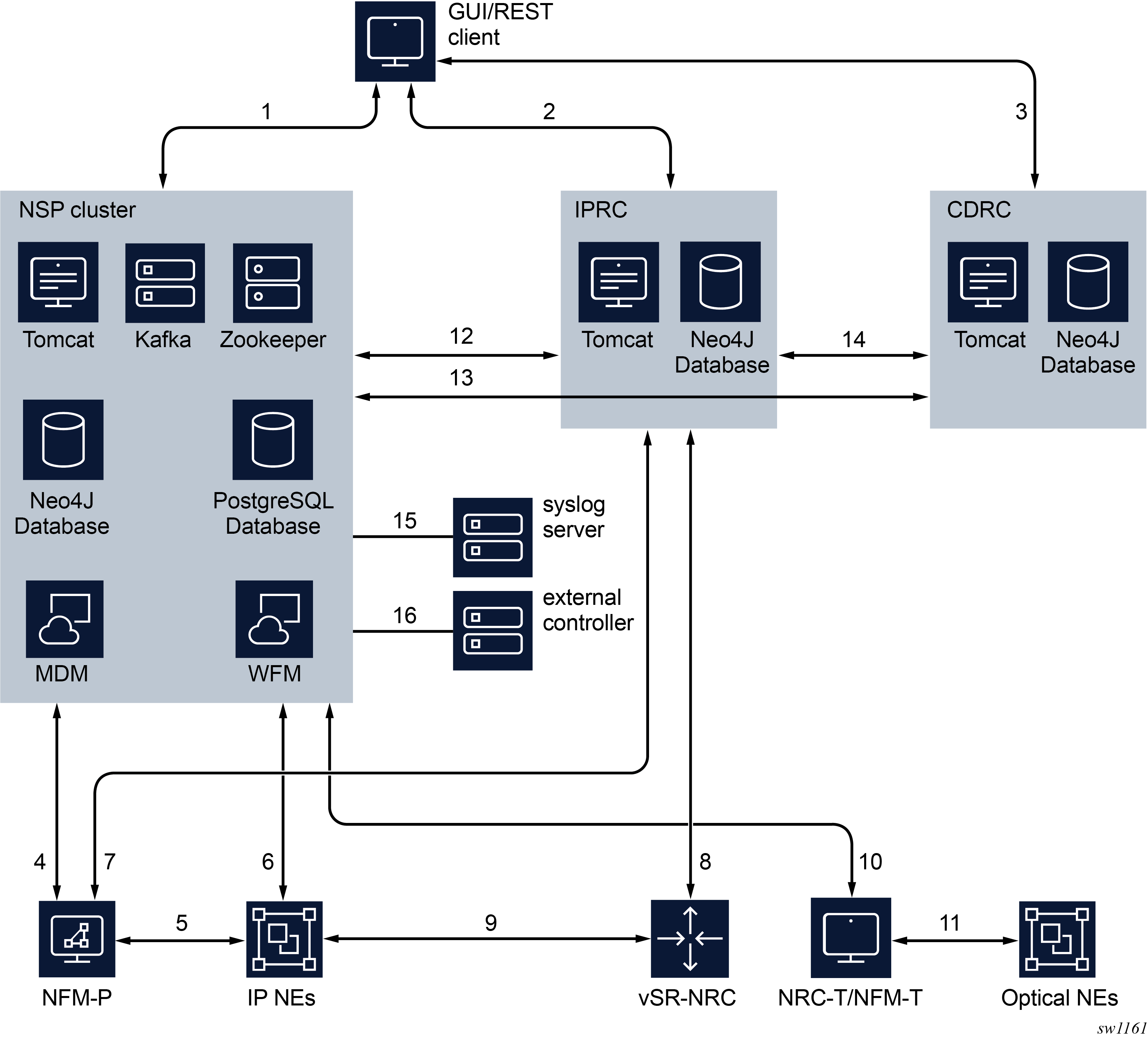
NSP architecture shows the architecture of the NSP.
-
NSP cluster
The NSP cluster is the core component that hosts the common services (nspOS), as well as all the major NSP software applications. Among the applications hosted by the NSP cluster is the Model-driven Mediation (MDM), which provides mediation between model-driven NSP applications and Nokia or third-party network devices. The Workflow Manager (WFM) allows for the creation and execution of workflows. The NSP Baseline Analytics monitor network traffic to establish baselines and can flag anomalous traffic patterns.
-
IP resource control (IPRC)
The IPRC provides service provisioning and activation as well as the Network Resource Controller for packet networks (NRC-P). The NRC-P hosts a path computation engine and implements a stateful Path Computation Element (PCE). The PCE instantiates and manages LSPs across IP network elements (NEs), and supports RSVP and segment routing (SR) LSP technologies. It also provides flow-based protocols such as OpenFlow and BGP FlowSpec to perform intelligent traffic steering and to automate policy based redirection at the flow or route level.
-
Cross domain resource control (CDRC)
This component optimizes network resources across different layers and domains of IP/MPLS, and optical networks.
- simulation tool
A traffic engineering (TE) tool that can be used by network engineers to design a new network, or optimize and simulate failures in an existing network that is imported into the tool.
Packet network resource controller (NRC-P) architecture shows the NRC-P.
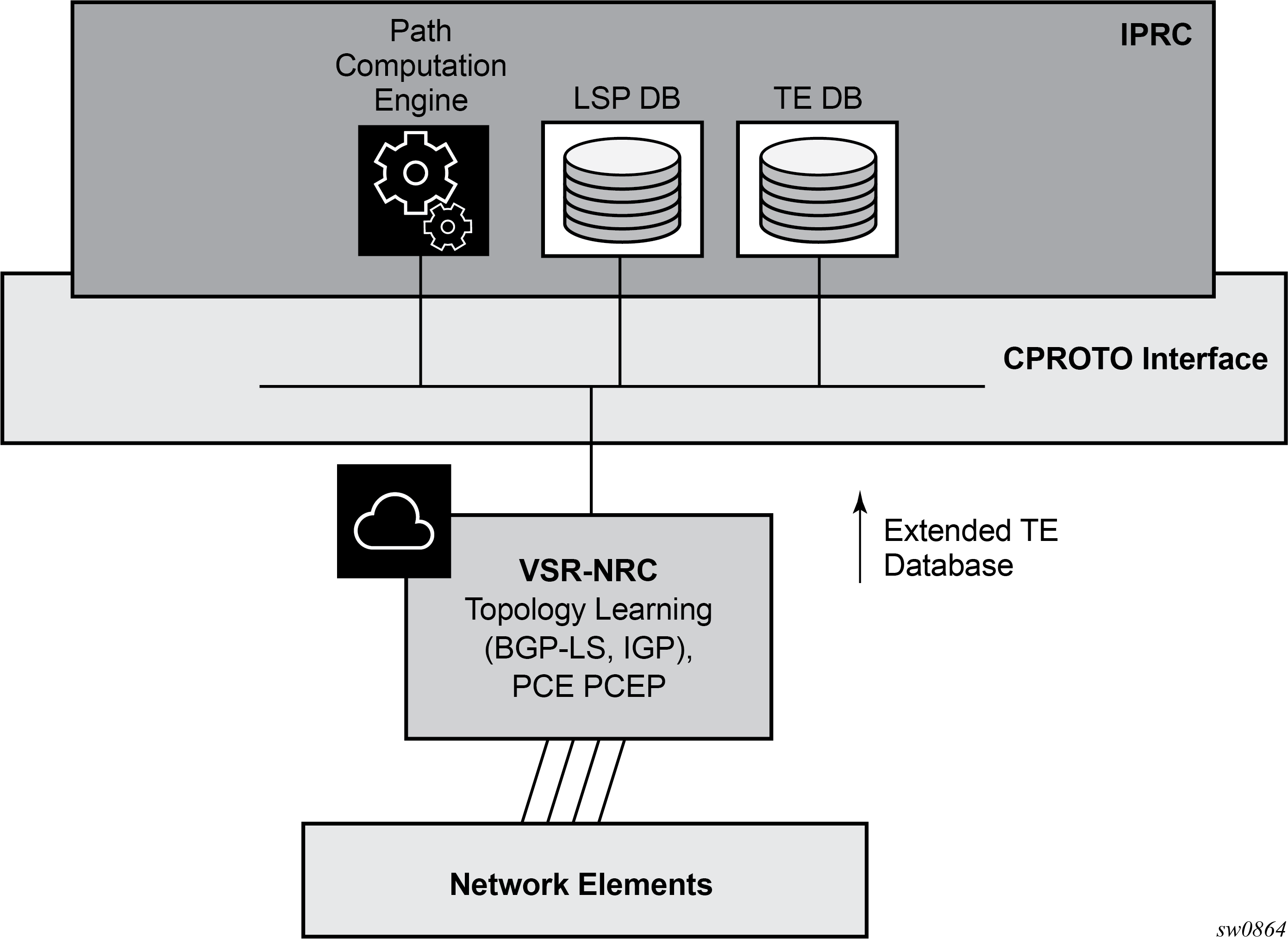
The NRC-P has the following architecture:
-
a single Virtual Machine (VM) handling the Java implementation of an MPLS path computation engine, a Traffic Engineering graph database (TE-DB), and an LSP database (LSP-DB). This is part of the IPRC as shown in NSP architecture.
-
a single VM running an SR OS image handles the functions of topology discovery of multiple IGP instances and areas through IGP or BGP-LS and the PCE PCEP functions. This is referred to as the VSR Network Resource Controller (VSR-NRC).
-
a plug-in adapter using the Nokia cproto interface, provides reliable, TCP-based message delivery between VSR-NRC and the IPRC. The plug-in adapter implements a compact encoding/decoding (codec) function for the message content using Google Protocol Buffers (protobuf). Google protobuf also provides for automatic C++ (VSR-NRC side) and Java (IPRC side) code generation to process the exchanged message content.
The VSR-NRC implements a PCEP PCE function, an OpenFlow controller, a BMP station database, a Route Origination Module (ROM), and a TE database populated using IGP and BGP-LS.
The NRC-P module of the NSP and the VSR-NRC communicate using a reliable proprietary TCP-based channel called cproto. The NRC-P module acts as the client side, it is the module which always initiates the establishment of the cproto session toward the VSR-NRC. This connection is established out-of-band using the management interface and can use the management interface IPv4 or IPv6 address as the local address.
The message data within the cproto channel is encoded and serialized using Google protobuf.
The VSR-NRC implements an NSP-Proxy module that manages all databases and channels used in the communications with the NRC-P. The NSP-Proxy opens a dedicated UDP port number 4199 for this communication and operates as the server side. This port is managed by the NSP-PROXY.
- PCEP – exchanges parameters and state information for RSVP-TE and SR-TE LSPs established using PCEP
- OPEN_FLOW – exchanges parameters and state information for flows established using OpenFlow
- BGP_LS – passes topology discovered using BGP-LS and IGP
- BMP_STATION – passes per-BGP family route information learned using BGP or BMP peering with the network
- ROM_SRTE – ROM for BGP families sr-policy-ipv4 and sr-policy-ipv6
- ROM_IPV4/V6 – ROM for BGP families IPv4 and IPv6
- ROM_FLOSPEC – ROM for BGP families flowspec-ipv4 and flowspec-ipv6
- ROM_LABELV4/V6 – ROM for BGP families label-ipv4 and label-ipv6
- Global Health and Notification – exchanges channel health and notification messages that are not application specific
The NRC-P, via the VSR-NRC, uses PCEP to communicate with its clients, referred to as PCE Clients (PCCs). Each router acting as a PCC initiates a PCEP session to the PCE in its domain.
When the user enables PCE control for one or more SR-TE or RSVP-TE LSPs, the PCE owns the path updating and periodic re-optimization of the LSP. In this case, the PCE acts in an active stateful role. The PCE can also act in a stateful passive role for other LSPs on the router by discovering them and taking into account their resource consumption when computing the path for the LSPs it has control ownership of.
The following is a high-level description of the PCE and PCC capabilities:
-
base PCEP implementation, per RFC 5440
-
active and passive stateful PCE LSP update, in accordance with RFC 8231, Path Computation Element Communication Protocol (PCEP) Extensions for Stateful PCE
-
delegation of LSP control to PCE
-
synchronization of the LSP database (LSP-DB) with network elements for PCE-controlled LSPs and network element-controlled LSPs
-
support for the RSVP-TE P2P LSP type
-
support for the SR-TE P2P LSP type, in accordance with draft-ietf-pce-segment-routing-08, PCEP Extensions for Segment Routing
-
support for PCC-initiated LSPs, in accordance with RFC 8231, Path Computation Element Communication Protocol (PCEP) Extensions for Stateful PCE
-
support for PCE-initiated LSPs, in accordance with RFC 8281, PCEP Extensions for PCE-initiated LSP Setup in a Stateful PCE Model
-
support for LSP path diversity across different LERs using extensions to the PCE path profile, in accordance with draft-alvarez-pce-path-profiles
-
support for LSP path bidirectionality constraints using extensions to the PCE path profile, in accordance with draft-alvarez-pce-path-profiles
- support for the PCEP ASSOCIATION object for SR-TE LSPs, in accordance with RFC 8697, for signaling path diversity constraints (in accordance with RFC 8800) and policy constraints (in accordance with draft-ietf-pce-association-policy-16), and PCE-initiated SR-TE LSPs
PCC and PCE configuration
The following PCE parameters cannot be modified while the PCEP session is operational:
- local-address
- local-address-ipv6
- keepalive
- dead-timer
The unknown-message-rate PCE parameter can be modified while the PCEP session is operational.
The following PCC parameters cannot be modified while the PCEP session is operational:
- local-address
- local-address-ipv6
- keepalive
- dead-timer
- peer (regardless of the shutdown state in classic CLI or the administrative state in the MD-CLI)
The following PCC parameters can be modified while the PCEP session is operational:
- report-path-constraints
- unknown-message-rate
Base implementation of PCE
The base implementation of PCE uses the PCEP extensions defined in RFC 5440.
The main functions of the PCEP are:
-
establishing, maintaining, and closing PCEP sessions
-
generating path computation requests using the PCReq message
-
generating path computation replies using the PCRep message
-
generating notification messages (PCNtf) by which the PCEP speaker can inform its peer about events, such as path request cancellation by the PCC or path computation cancellation by the PCE
-
generating error messages (PCErr) by which the PCEP speaker can inform its peer about errors related to processing requests, message objects, or TLVs
The following table lists the base PCEP messages and objects.
| TLV, object, or message | Contained in object | Contained in message |
|---|---|---|
|
OPEN object |
— |
OPEN, PCErr |
|
Request Parameter (RP) object |
— |
PCReq, PCRep, PCErr, PCNtf |
|
NO-PATH object |
— |
PCRep |
|
END-POINTS object |
— |
PCReq |
|
BANDWIDTH object |
— |
PCReq, PCRep, PCRpt, PCInitiate |
|
METRIC object |
— |
PCReq, PCRep, PCRpt, PCInitiate |
|
Explicit Route Object (ERO) |
— |
PCRep |
|
Reported Route Object (RRO) |
— |
PCReq |
|
LSPA object |
— |
PCReq, PCRep, PCRpt, PCInitiate |
|
NOTIFICATION object |
— |
PCNtf |
|
PCEP-ERROR object |
— |
PCErr |
|
CLOSE object |
— |
CLOSE |
| ASSOCIATION object | – | PCReq, PCRpt, PCRep, PCUpd, PCInitiate |
The behavior and limitations of the implementation of the objects in Base PCEP message objects and TLVs are as follows:
-
The PCE treats all supported objects received in a PCReq message as mandatory, regardless of whether the P-flag in the common header of the object is set (mandatory object) or not (optional object).
-
The PCC implementation always sets the B-flag (B=1) in the METRIC object containing the hop metric value, which means that a bound value must be included in the PCReq message. The PCE returns the computed value in the PCRep message with flags set identically to the PCReq message.
-
The PCC implementation always sets flags B=0 and C=1 in the METRIC object for the IGP or TE metric values in the PCReq message. This means that the request is to optimize (minimize) the metric without providing a bound. PCE returns the computed value in PCRep message with flags set identically to the PCReq message.
-
The IRO and LOAD-BALANCING objects are not supported in the NSP PCE feature. If the PCE receives a PCReq message with one or more of these objects, it ignores them regardless of the setting of the P-flag and processes the path computations normally.
-
LSP path setup and hold priorities are configurable during SR-TE LSP configuration on the router, and the PCC passes the configurations on in an LSPA object. However, the PCE does not implement LSP preemption.
-
The LSPA, METRIC, and BANDWIDTH objects are also included in the PCRpt message.
The following features are not supported in SR OS:
-
PCE discovery using IS-IS (as defined in RFC 5089) and OSPF (as defined in RFC 5088) along with corresponding extensions for discovering stateful PCE (as defined in draft-sivabalan-pce-disco-stateful)
-
security of the PCEP session using MD5 or TLS between PCEP peers
-
PCEP synchronization optimization (as defined in draft-ietf-pce-stateful-sync-optimizations)
-
support of end-to-end secondary backup paths for an LSP
-
jitter, latency, and packet loss metrics support (as defined in RFC 7471 and draft-ietf-isis-te-metric-extensions) and their use in the PCE METRIC object (as defined in draft-ietf-pce-pcep-service-aware)
- ASSOCIATION object for RSVP LSPs
PCEP session establishment and maintenance
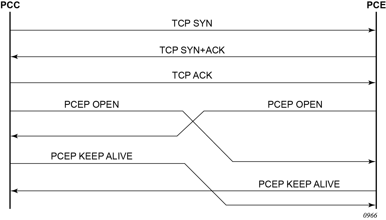
The PCEP protocol operates over TCP using destination TCP port 4189. The PCE client (PCC) always initiates the connection. After the user configures the PCEP local IPv4 or IPv6 address and the peer IPv4 or IPv6 address on the PCC, the PCC initiates a TCP connection to the PCE. If both a local IPv4 and a local IPv6 address are configured, the connection uses the local address of the same family as the peer address. When the connection is established, the PCC and PCE exchange OPEN messages, and this process initializes the PCEP session and exchanges the session parameters to be negotiated.
By default, the PCC attempts to reach the remote PCE address out of band using the management port. If it cannot, it attempts to reach the remote PCE address in band. The user can modify the configuration of the peer to attempt connecting in band only or out of band only. When the session comes up out of band, the management IP address is used as the local address. The local IPv4 or IPv6 address configured by the user is only used for in-band sessions and is otherwise ignored.
A keepalive mechanism is used as an acknowledgment of the acceptance of the session within the negotiated parameters. It is also used as a maintenance function to detect whether the PCEP peer is still alive.
The negotiated parameters include the keepalive timer and the dead timer, and one or more PCEP capabilities such as support of stateful PCE and the SR-TE LSP path type.
The following figure shows PCEP session initialization steps.
If the session to the PCE times out, the router acting as a PCC keeps the last successfully-programmed path provided by the PCE until the session to the PCE is reestablished. Any subsequent change to the state of an LSP is synchronized at the time the session is reestablished.
When a PCEP session to a peer times out or closes, the rate at which the PCEP speaker attempts the establishment of the session is subject to an exponential back-off mechanism.
PCEP parameters
The following PCEP parameters are user-configurable on both the PCC and PCE. On the PCE, the configured parameter values are used on sessions to all PCCs.
-
keepalive timer
A PCEP speaker (PCC or PCE) must send a keepalive message if no other PCEP message is sent to the peer at the expiry of this timer. This timer is restarted every time a PCEP message is sent or the keepalive message is sent.
The keepalive mechanism is asymmetric, meaning that each peer can use a different keepalive timer value.
The range of this parameter is 1 to 255 seconds, and the default value is 30 seconds. The no version returns to the default value.
-
dead timer
This timer tracks the amount of time a PCEP speaker (PCC or PCE) waits after the receipt of the last PCEP message before declaring its peer down.
The dead timer mechanism is asymmetric, meaning that each PCEP speaker can propose a different dead timer value to its peer to use to detect session timeouts.
The range of this parameter is 1 to 255 seconds, and the default value is 120 seconds. The no version returns to the default value.
-
maximum rate of unknown messages
When the rate of received unrecognized or unknown messages reaches this limit, the PCEP speaker closes the session to the peer.
-
session redelegation and state timers
If the PCEP session to the PCE goes down, all delegated PCC-initiated LSPs have their state maintained in the PCC and are not timed out. The PCC continues to try reestablishing the PCEP session. When the PCEP session is reestablished, the LSP database is synchronized with the PCE, and any LSP that went down since the last time the PCEP session was up has its path updated by the PCE. The redelegation timer and state timer are known as the Redelegation Timeout Interval and State Timeout Interval respectively in RFC 8231.
Stateful PCE
The main function introduced by stateful PCE over the base PCE implementation is the ability to synchronize the LSP state between the PCC and the PCE. This allows the PCE to have all the required LSP information to perform re-optimization and updating of the LSP paths.
The following table describes the messages and objects supported by stateful PCE in the SR OS.
| TLV, object, or message | Contained in object | Contained in message |
|---|---|---|
|
Path Computation State Report (PCRpt) message |
— |
New message |
|
Path Computation Update Request (PCUpd) message |
— |
New message |
|
Stateful PCE Capability TLV |
OPEN |
OPEN |
|
Stateful Request Parameter (SRP) object |
— |
PCRpt, PCErr, PCInitiate |
|
LSP object |
ERO |
PCRpt, PCReq, PCRep, PCInitiate |
|
LSP Identifiers TLV |
LSP |
PCRpt |
|
Symbolic Path Name TLV |
LSP, SRP |
PCRpt, PCInitiate |
|
LSP Error Code TLV |
LSP |
PCRpt |
|
RSVP Error Spec TLV |
LSP |
PCRpt |
| ASSOCIATION object | – | PCRpt, PCReq, PCRep, PCInitiate, PCUpd |
The behavior and limitations of the implementation of the objects in PCEP stateful PCE extension objects and TLVs are as follows:
-
The PCC and PCE support all PCEP capability TLVs defined in this document and always advertise them. If the OPEN object received from a PCEP speaker does not contain one or more of the capabilities, neither the PCE nor the PCC use them during that specific PCEP session.
-
The PCC always includes the LSP object in the PCReq message to ensure that the PCE can correlate the PLSP-ID for this LSP when a subsequent PCRpt message arrives with the delegation bit set. The PCE does, however, still honor a PCReq message without the LSP object.
-
PCE path computation only considers the bandwidth used by LSPs in its LSP-DB. As a result, there are two situations where PCE path computation does not accurately account for the bandwidth used in the network:
-
When there are LSPs that are signaled by the routers but are not synchronized with the PCE. The user can enable the reporting of the LSP to the PCE LSP database for each LSP.
-
When the stateful PCE is peering with a third-party stateless PCC, implementing only the original RFC 5440. While the PCE is able to bring the PCEP session up, the LSP database is not updated, because stateless PCC does not support the PCRpt message. As such, PCE path computation does not accurately take into account the bandwidth used by these LSPs in the network.
-
-
The PCE ignores the Re-optimize flag (R-flag) in the PCReq message when acting in stateful-passive mode for an LSP and always returns the new computed path, regardless if it is link-by-link identical or has the same metric as the current path. The decision whether to initiate the new path in the network belongs to the PCC.
-
The SVEC object is not supported in SR OS nor in the NSP. If the PCE receives a PCReq message with the SVEC object, it ignores the SVEC object and treats each path computation request in the PCReq message as independent, regardless of the setting of the P-flag in the SVEC object common header.
-
When an LSP is delegated to the PCE, there can be no prior state in the NRC-P LSP database for the LSP. This could be because of the PCE not having received a PCReq message for the same PLSP-ID. For the PCE to become aware of the original constraints of the LSP, the following additional procedures are performed:
-
The PCC appends a duplicate of each of the LSPA, METRIC, and BANDWIDTH objects in the PCRpt message. The only difference between the two objects of the same type is that the P-flag is set in the common header of the duplicate object to indicate a mandatory object for processing by the PCE.
-
The value of the metric or bandwidth in the duplicate object contains the original constraint value, while the first object contains the operational value. This is applicable to hop metrics in the METRIC object and BANDWIDTH object only. SR OS PCC does not support putting a bound on the IGP or TE metric in the path computation.
-
The path computation on the PCE uses the first set of objects when updating a path if the PCRpt message contains a single set. If the PCRpt message contains a duplicate set, the PCE path computation must use the constraints in the duplicate set.
-
For interoperability, implementations compliant to PCEP standards should be able to accept the first METRIC object and ignore the second object without additional error handling. Because there are also BANDWIDTH and LSPA objects, the [no] report-path-constraints command is provided in the PCC on a per-PCEP session basis to disable the inclusion of the duplicate objects. Duplicate objects are included by default.
-
Stateful PCE uses the additional messages, TLVs, and objects described in the following table for PCE initiation of LSPs.
| TLV, object, or message | Contained in object | Contained in message |
|---|---|---|
|
PCE LSP Initiate Message (PCInitiate) |
— |
New message |
|
PCC LSP Create Flag (C-Flag) |
LSP |
PCRpt |
|
PATH_PROFILE_ID TLV |
Path Profile |
— |
PCEP extensions in support of SR-TE LSPs
To manage the path of an SR-TE LSP, the PCE and PCC both implement the following extensions to PCEP in support of segment routing:
-
An SR-PCE-CAPABILITY in the OPEN object to indicate support of segment routing tunnels by the PCE and the PCC during PCEP session initialization.
The PCEP speaker on the transmit side encodes the SR-PCE-CAPABILITY as both a top-level TLV in the OPEN object and as a sub-TLV of the PATH SETUP TYPE CAPABILITY TLV in the OPEN object. The PCEP speaker on the receive side processes the SR-PCE-CAPABILITY, which it implements at the TLV level and ignores the sub-TLV. The PCEP speaker performs the following actions:
- A PCEP speaker that implements RFC 8664 and which receives both the top-level SR-PCE-CAPABILITY TLV and the top-level PATH SETUP TYPE CAPABILITY TLV processes the SR-PCE-CAPABILITY sub-TLV in the top-level PATH SETUP TYPE CAPABILITY TLV.
- A PCEP speaker that implements RFC 8664 and which receives only the top-level SR-PCE-CAPABILITY TLV treats it as if it received the top-level PATH SETUP TYPE CAPABILITY TLV with PST={0,1}, meaning both RSVP-TE and SE-TE LSP types are supported, along with the SR-PCE-CAPABILITY sub-TLV.
- A PCEP speaker that implements up to version draft-ietf-pce-segment-routing-08 and which receives both the top-level SR-PCE-CAPABILITY TLV and the top-level PATH SETUP TYPE CAPABILITY TLV processes the top-level SR-PCE-CAPABILITY and ignores the top-level PATH SETUP TYPE CAPABILITY TLV.
This implementation is in accordance with the backward compatibility procedure defined in RFC 8664 to process the SR-PCE-CAPABILITY.
If the OPEN object is received from a PCEP speaker without the SR-PCE-CAPABILITY in either or both of the preceding encodings, the PCE or the PCC does not send or accept PCEP messages for LSP paths of type SR-TE on that specific PCEP session.
-
A Path Setup Type TLV for SR-TE LSPs to be included in the Stateful PCE Request Parameters (SRP) object during the path report (PCRpt) messages by the PCC.
A Path Setup Type TLV with a value of 1 identifies an SR-TE LSP.
-
A Segment Routing ERO and an RRO with subobjects, referred to as SR-ERO and SR-RRO subobjects, which encode the SID information in the PCRpt messages.
-
The PCE implementation supports the Segment-ID (SID) Depth value in the METRIC object. This is always signaled by the PCC in the PCEP OPEN object as part of the as SR-PCE-CAPABILITY TLV. It is referred to as the Maximum Stack Depth (MSD). In addition, the per-LSP value for the max-sr-labels option, if configured, is signaled by the PCC to the PCE in the Segment-ID (SID) Depth value in a METRIC object for both a PCE-computed LSP and a PCE-controlled LSP. PCE computes and provides the full explicit path with the TE-links specified. If there is no path with the number of hops lower than the MSD value, or the Segment-ID (SID) Depth value if signaled, a reply with no path is returned to the PCC. For a PCC-controlled LSP, if the label stack returned by the TE-DB’s hop-to-label translation exceeds the per-LSP maximum SR label stack size, the LSP is brought down.
-
If the Path Setup Type (PST) TLV is not included in the PCReq message, the PCE or PCC must assume the message is for an RSVP-TE LSP.
PCEP segment routing extension objects and TLVs describes the segment routing extension objects and TLVs supported in the SR OS.
| TLV, object, or message | Contained in object | Contained in message |
|---|---|---|
|
SR-PCE-CAPABILITY TLV |
OPEN (both as top-level TLV and sub-TLV of PATH SETUP TYPE CAPABILITY TLV) |
OPEN |
|
PATH SETUP TYPE CAPABILITY TLV |
OPEN |
OPEN |
|
SR-ERO Sub-object |
ERO |
PCRep, PCRpt |
|
SR-RRO Sub-object |
RRO |
PCReq, PCRpt |
|
Segment-ID (SID) Depth Value in METRIC object |
METRIC |
PCReq, PCRpt |
PCEP over TLS
PCEP over TLS (PCEPS) is secured using TLS on port 4189. The PCC is configured with a TLS client profile to initiate the TLS handshake. The PCE is configured with a TLS server profile to allow PCEP over TLS. When a TLS server profile is configured on the PCE, the PCE can establish TLS and non-TLS connections, in PCE secured (PCES) and PCE modes. See PCE behavior for more information about the modes supported by SR OS.
In TLS mode, both the PCC and PCE must provide certificates for authentication. The PCE provides the server certificate to the PCC and requires the client certificate to authenticate the PCC.
TLS handshake
SR OS supports TLS client (PCC) and server (PCE) functionality, and TLS bidirectional authentication, where the PCE requests the client certificate to authenticate the PCC.
In a typical TLS handshake, the client starts the handshake with a ClientHello message. The server provides the server certificate for authentication to the client and sends a list of server-accepted ciphers.
The server can optionally ask the client to provide the client certificate using the server CertificateRequest option. When this option is present, the client provides the server with the client certificate and, if authenticated, the TLS symmetric key is negotiated and the TLS session is established. The symmetric key is used to encrypt the TLS datapath.
See the 7450 ESS, 7750 SR, 7950 XRS, and VSR System Management Guide for more information about the TLS handshake steps.
PCEP session over TLS
To establish a PCEP session over TLS as specified in RFC 8253, the PCC sends a StartTLS message to the PCE to initiate the TLS negotiation. The PCC activates the StartTLS timer and waits for the StartTLS message from the PCE. The timer is configured using the configure router pcep pcc peer tls-wait-timer command; the default timer is 60 seconds.
If the PCE is TLS-capable and sends back a StartTLS message before the StartTLS timer expires, the TLS handshake is initiated. If the PCE sends an Open message or does not send back a StartTLS message, the PCC responds with an error message, closes the TCP connection, and retries to establish the connection. The PCEP Message-Type field of the PCEP common header for the StartTLS message is set to 13, as specified in RFC 8253. The following figure shows the establishment of a PCEP session over TLS.
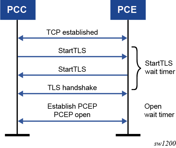
TLS supports both in-band and out-of-band PCE connections. The following figure shows the PCE and PCC TLS support.
PCC behavior
On the PCC, SR OS supports only strict TLS. That is, both PCE and PCC must support TLS and perform a successful TLS handshake before the TLS wait timer expires. Otherwise, the PCC retries the connection after 60 seconds.
Use the following commands to configure the PCC:
- configure router pcep pcc peer tls-client-profile
- configure router pcep pcc peer tls-wait-timer
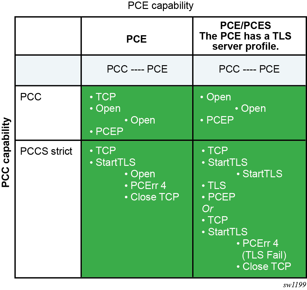
PCE behavior
On the PCE, SR OS supports TLS or non-TLS mode. That is, when a TLS profile is configured on the PCE, the PCE accepts PCC connections that are TLS-secure or unsecured. To configure the TLS profile on the PCE, use the configure router pcep pce tls-server-profile command.
In the PCES and PCE mode, SR OS accepts connections with a StartTLS message or an Open message from the PCC. Depending on the PCC that sends the StartTLS message, the PCE sends back a StartTLS message also.
In the PCE-only mode, SR OS accepts only Open messages from the PCC; StartTLS messages are not accepted.
In the PCES strict mode, the PCE accepts only TLS connections from the PCC. Non-TLS connections (which open PCEP connections with the Open message, not with the StartTLS message) are not accepted and the TCP connection is closed. SR OS does not support PCES strict mode.
LSP initiation
An LSP that is configured on the router is referred to as a PCC-initiated LSP. An LSP that is not configured on the router, but is instead created by the PCE at the request of an application or a service instantiation, is referred to as a PCE-initiated LSP.
The SR OS supports three different modes of operations for PCC-initiated LSPs which are configurable on a per-LSP basis.
-
When the path of the LSP is computed and updated by the router acting as a PCE Client (PCC), the LSP is referred to as a PCC-initiated and PCC-controlled LSP.
A PCC-initiated and PCC-controlled LSP has the following characteristics:
-
The LSP can contain strict or loose hops, or a combination of both.
-
CSPF is supported for RSVP-TE LSPs. Local path computation takes the form of hop-to-label translation for SR-TE LSPs.
-
LSPs can be reported to synchronize the LSP database of a stateful PCE server using the pce-report option. In this case, the PCE acts in passive stateful mode for this LSP. The LSP path cannot be updated by the PCE. In other words, the control of the LSP is maintained by the PCC.
-
-
When the path of the LSP is computed by the PCE at the request of the PCC, it is referred to as a PCC-initiated and PCE-computed LSP.
A PCC-initiated and PCE-computed LSP has the following characteristics:
-
The user must enable the path-computation-method pce option for the LSP so that the PCE can perform path computations at the request of the PCC only. The PCC retains control.
-
LSPs can be reported to synchronize the LSP database of a stateful PCE server using the pce-report option. In this case, the PCE acts in passive stateful mode for this LSP.
-
-
When the path of the LSP is updated by the PCE following a delegation from the PCC, it is referred to as a PCC-initiated and PCE-controlled LSP.
A PCC-initiated and PCE-controlled LSP has the following characteristics:
-
The user must enable the pce-control option for the LSP so that the PCE can perform path updates following a network event without an explicit request from the PCC. The PCC delegates full control.
-
The user must enable the pce-report option for LSPs that cannot be delegated to the PCE. The PCE acts in active stateful mode for this LSP.
-
SR OS also supports PCE-initiated LSPs. PCE-initiated LSPs allow a WAN SDN controller (such as the NSP) to automatically instantiate an LSP based on a service or application request. Only SR-TE PCE-initiated LSPs are supported.
The instantiated LSP does not have a configuration on the network routers and, consequently, is treated the same way as an auto-LSP. The parameters of the LSP are provided using policy lookup in the NSP and are passed to the PCC using PCEP in accordance with RFC 8281. Missing LSP parameters are added using a default or specified LSP template on the PCC.
PCE-initiated LSPs have the following characteristics:
-
The user must enable pce-initiated-lsp sr-te to enable the PCC to accept and process the PCInitiate messages from the PCE.
-
The user must configure one or more LSP templates of type pce-init-p2p-srte for SR-TE LSPs. A default template is supported that is used for LSPs for which no ID or an ID of 0 is included in the PCInitiate message. The user must configure at least one default PCE-initiated LSP template.
PCE-initiated LSPs are a form of SR-TE auto-LSP and are available to the same forwarding contexts. See Forwarding contexts supported with SR-TE auto-LSP. Similar to other auto-LSPs, PCE-initiated messages are installed in the TTM and are therefore available to advanced policy-based services using auto-bind such as VPRN and E-VPN. However, PCE-initiated LSPs cannot be used with provisioned SDPs.
PCC-initiated and PCE-computed or controlled LSPs
The following is the procedure to configure and program a PCC-initiated SR-TE LSP when control is delegated to the PCE.
-
The LSP configuration is created on the PE router via CLI or via the
OSS/NSP NFM-P.
The configuration dictates which PCE control mode is needed: active (pce-control and pce-report options enabled) or passive (path-computation-method pce enabled and pce-control disabled).
-
The PCC assigns a unique PLSP-ID to the LSP.
The PLSP-ID uniquely identifies the LSP on a PCEP session and must remain constant during its lifetime. PCC on the router must keep track of the association of the PLSP-ID to the Tunnel-ID and Path-ID, and use the latter to communicate with MPLS about a specific path of the LSP. PCC also uses the SRP-ID to correlate the PCRpt messages for each new path of the LSP.
-
The PE router does not validate the entered path.
Note, however, that in SR OS, the PCE supports the computation of a path for an LSP with empty-hops in its path definition. While PCC includes the IRO objects in the PCReq message to PCE, the PCE ignores them and compute the path with the other constraints except the IRO.
-
The PE router sends a PCReq message to the PCE to request a path for the LSP.
The PCReq message includes the LSP parameters in the METRIC object, the LSPA object, and the BANDWIDTH object. The PE router also includes the LSP object with the assigned PLSP-ID. At this point, the PCC does not delegate the control of the LSP to the PCE.
-
The PCE computes a new path, reserves the bandwidth, and returns the path
in a PCRep message with the computed ERO in the ERO object. It also includes
the LSP object with the unique PLSP-ID, the METRIC object with any computed
metric value, and the BANDWIDTH object.
Note: For the PCE to be able to use the SRLG path diversity and admin-group constraints in the path computation, the user must configure the SRLG and admin-group membership against the MPLS interface and ensure that the traffic-engineering option is enabled in IGP. This causes IGP to flood the link SRLG and admin-group membership in its participating area, and for PCE to learn it in its TE database.
-
The PE router updates the CPM and the datapath with the new path.
Up to this point, the PCC and PCE are using passive stateful PCE procedures. The next steps synchronize the LSP database of the PCC and PCE for both PCE-computed and PCE-controlled LSPs. They also initiate the active PCE stateful procedures for the PCE-controlled LSP only.
-
The PE router sends a PCRpt message to update the PCE with an up state, and also
sends the RRO as confirmation.
It now includes the LSP object with the unique PLSP-ID. For a PCE-controlled LSP, the PE router also sets the delegation control flag to delegate control to the PCE. The state of the LSP is now synchronized between the router and the PCE.
-
Following a network event or a re-optimization, the PCE computes a new path for a
PCE-controlled LSP and returns it in a PCUpd message with the new ERO.
It includes the LSP object with the same unique PLSP-ID assigned by the PCC, as well as the Stateful Request Parameter (SRP) object with a unique SRP-ID number to track error and state messages specific to this new path.
- The PE router updates the CPM and the data path with the new path.
-
The PE router sends a PCRpt message to inform the PCE that the older path is
deleted.
It includes the unique PLSP-ID value in the LSP object and the Remove (R) bit set.
-
The PE router sends a new PCRpt message to update PCE with an up state, and also
sends the RRO to confirm the new path.
The state of the LSP is now synchronized between the router and the PCE.
-
If PCE owns the delegation of the LSP and is making a path update, MPLS initiates
the LSP and update the operational value of the changed parameters while the
configured administrative values do not change.
Both the administrative and operational values are shown in the details of the LSP path in MPLS.
- If the user makes any configuration change to the PCE-computed or PCE-controlled LSP, MPLS requests that the PCC first revoke delegation in a PCRpt message (PCE-controlled only), and then MPLS and the PCC follow the preceding steps to convey the changed constraint to the PCE. This results in the programming of a new path into the data path, the synchronization of the PCC and PCE LSP databases, and the return of delegation to the PCE.
The preceding procedure is followed when the user performs a no shutdown command on a PCE-controlled or PCE-computed LSP. The starting point is an LSP which is administratively down with no active path.
For an LSP with an active path, the following items apply:
-
If the user enabled the path-computation-method pce option on a PCC-controlled LSP with an active path, no action is performed until the next time the router needs a path for the LSP following a network event of a LSP parameter change. At that point, the preceding procedure is followed.
-
If the user enabled the pce-control option on a PCC-controlled or PCE-computed LSP with an active path, the PCC issues a PCRpt message to the PCE with an up state, as well as the RRO of the active path. It sets the delegation control flag to delegate control to the PCE. The PCE keeps the active path of the LSP and make no updates to it until the next network event or re-optimization. At that point, the preceding procedure is followed.
Configuring PCE-initiated LSPs
-
Enable the pce-initiated-lsp sr-te command using the CLI or
using the OSS.
Optionally, configure a limit to the number of PCE-initiated LSPs that the PCE can instantiate on a node using the max-srte-pce-init-lsps command in the CLI or using the OSS.
-
Configure at least one LSP template of type using the
pce-init-p2p-srte command to select the value of the LSP
parameters that remain under the control of the PCC.
At a minimum, a default template should be configured (type pce-init-p2p-srte default). In addition, LSP templates with a defined template ID can be configured. The template ID can be included in the path profile of the PCInitiate message to indicate which non-default template to use for a particular LSP. If the PCInitiate message does not include the PCE path profile, MPLS uses the default PCE-initiated LSP template. LSP template parameters lists the applicable LSP template parameters. These are grouped into:
-
parameters that are controlled by the PCE and that the PCC cannot change (invalid, implicit, and signaled in PCEP)
-
parameters that are controlled by the PCC and are used for signaling the LSP in the control plane
-
parameters that are controlled by the PCC and are related to the usability of the LSP by MPLS and other applications such as routing protocols, services, and OAM
The user can configure these parameters in the template.
Table 5. LSP template parameters Controlled by PCE Controlled by PCC Invalid Implicit Signaled in PCEP LSP signaling options LSP usability options auto-bandwidth
pce-report
bandwidth
—
—
retry-limit
—
exclude
—
bgp-shortcut
retry-timer
pce-control
from
—
bgp-transport-tunnel
shutdown
pce-report
hop-limit
default-path (mandatory, must be empty)
—
least-fill
path-computation-method pce
include
—
—
metric-type
—
—
—
entropy-label
—
—
—
—
override-tunnel-elc
—
—
setup-priority
—
igp-shortcut
—
—
hold-priority
—
—
—
—
—
—
load-balancing-weight
—
—
—
—
max-sr-labels
—
—
—
—
additional-frr-labels
—
—
—
—
metric
—
—
—
—
vprn-auto-bind
—
—
—
—
admin-tag
All PCE-initiated LSPs that use a particular LSP template are deleted if the user deletes the template. The default template can be created or deleted if the pce-initiated-lsp>sr-te context does not exist. However, the pce-init-p2p-sr-te default lsp-template cannot be deleted if the pce-initiated-lsp>sr-te context exists and is not shutdown. This context must be shutdown to delete the pce-init-p2p-sr-te default LSP template, which brings down all PCE-initiated LSPs. The pce-initiated-lsp>sr-te context cannot be administratively enabled if the pce-init-p2p-sr-te default lsp-template is not configured.
A shutdown of an LSP template does not bring down any already established LSPs. Parameters can only be changed when in the shutdown state and the changes do not take effect until a no shutdown is performed. This means that PCE updates use older parameters if the template is still shut down.
MPLS copies the lsp-template parameters into the lsp-entry when a PCE initiated LSP is created. MPLS handles lsp-updates based on the last copied parameters.
After the lsp-template parameter changes, when the lsp-template is no shutdown.
-
MPLS copies the related TTM parameters (listed below) into the LSP entry, and updates TTM
-
If there is a change in max-sr-labels, MPLS reevaluates the related LSPs, and brings paths down if applicable (for example, if current hopCount is greater than the applicable max-sr-labels value).
The TTM LSP-related parameters include:-
Metric
-
VprnAutoBind
-
LoadBalWeight
-
MaxSrLabels
-
AdditionalFrrLabels
-
MetricOffset
-
IgpShortCut
-
IgpShortcutLfaOnly
-
IgpShortcutLfaProtect
-
LspBgpShortCut
-
LspBgpTransTunnel
-
A PCE-initiated LSP update request is accepted regardless of the LSP template administrative state, as follows:-
If the LSP template is administratively up, the system copies the LSP template parameters to the LSP/path.
-
If the LSP template is administratively down, the system uses the previously copied LSP template parameters and responds to the update with an LSP operUp report.
-
-
Set the redelegation and state timers on the PCC (known as the Redelegation Timeout
Interval and StateTimeout Interval respectively in RFC 8231).
The redelegation and state timers are started when the PCEP session goes down or the PCE signals overload. The redelegation timer applies to both PCC-initiated and PCE-initiated LSPs, while the state timer applies only to PCE-initiated LSPs. The redelegation and state timers are configured in the CLI or through management, as follows:
config>router>pcep>pcc>
[no] redelegation-timer seconds
[no] state-timer seconds [action {remove | none}]
If the delegated PCE-initiated LSPs cannot be redelegated by the time these timers expire, a configurable action is performed by the PCC. The supported actions are remove or none, with a default of remove.
-
After configuration, the PCE can then initiate and remove LSPs on the PCC.
These procedures are described in LSP instantiation using PCEP, LSP deletion using PCEP, and Dynamic state handling for PCE initiated LSPs.
LSP instantiation using PCEP
The following procedures are followed in the instantiation of a PCE-initiated LSP by both the NSP and SR OS router. Further protocol details can be found in RFC 8281.
NSP generation of the PCInitiate message
- When the PCEP session is established from the PCC to PCE, the PCC and PCE exchange the OPEN object and both set the LSP-INSTANTIATION CAPABILITY flag (I flag), in the STATEFUL-PCE-CAPABILITY TLV flag field.
-
The operator, using the north-bound REST interface, the NSD or another
interface, requests the NSP to initiate an LSP.
The following parameters are specified:
-
source address
-
destination address
-
LSP type (SR-TE)
-
bandwidth value
-
include/exclude admin-group constraints
-
optional PCE path profile ID for the path computation at the PCE
-
optional PCE-initiated LSP template ID for use by the PCC to complete the instantiation of the LSP
-
-
The NSP crafts the PCInitiate message and sends it to the PCC using PCEP.
The message contains the:
- LSP object with PLSP-ID=0
- SRP object
- ENDPOINTS object
- computed SR-ERO (SR-TE) object
- list of LSP attributes
- BANDWIDTH object
- one or more METRIC objects
- LSPA object
-
The PCE-initiated LSP template ID to be used at the PCC, if
any, is included in the PATH-PROFILE-ID TLV of the Path Profile object or the
Association ID in an ASSOCIATION object of type Policy.
The profile ID matches the PCE-initiated LSP template ID at the PCC and is not the same as the path profile ID used on the PCE to compute the path of this PCE-initiated LSP.Note: The range of the LSP template ID is 32-bits, but the range of the Association Group ID is only 16 bits. Therefore, the range of Association Group IDs that can be used to reference a template ID is limited to the bottom 16 bits of the 32-bit template ID range.
- The path profile ID is used on the PCE to compute the path of this PCE-initiated LSP.
SR OS router procedures on receiving a PCInitiate message
- If a PCInitiate message includes a name that is a duplicate of an existing LSP on the router, the system generates an error.
- The router assigns a PLSP-ID and looks up any specified PCE-initiated LSP template ID or the default PCE-initiated LSP template to retrieve the local parameters. This lookup uses the PATH-PROFILE-ID TLV if that is included in the PCInitiate message, or the Association ID of the Policy ASSOCIATION object if that is included in the PCInitiate message.
- The router instantiates the SR-TE LSP. The instantiated LSP is added to the TTM and is used by all applications that look up a tunnel in the TTM.
- The router crafts a PCRpt message with the tunnel ID, LSP ID, and the RRO and passes it along with the PLSP-ID set to the assigned value and the delegation bit set in the LSP object to the PCE.
NSP procedures on receiving a PCRpt message for a PCE
- The NSP confirms the bandwidth reservation and updates its LSP database. The PCC and PCE are synchronized at this point.
- The NSP reports the PLSP-ID and tunnel ID to the application, for example NSD, or to the operator that uses it in the specific application that originated the request.
- The PCE can perform updates to the path during the lifetime of the LSP by using the PCUpd message in the same way as with a delegated PCC-initiated LSP.
LSP deletion using PCEP
The following procedures apply in the deletion of a PCE-initiated LSP. More protocol level details are provided in RFC 8281. These procedures are applicable when the user manually deletes the PCE-initiated LSP or the NSP application, or when NSD requests the deletion of the PCE-initiated LSP. The procedures that apply when a network event occurs are described in SR OS router procedures.
The NSP crafts a PCInitiate message for the corresponding PLSP-ID and sets the R-bit in the SRP object flags to indicate to the PCC that it must delete the LSP. The NSP sends the message to the PCC using PCEP.
SR OS router procedures on receipt of a PCInitiate with the R-bit set
- The router deletes the state of the LSP.
- The router crafts a PCRpt message with the R-bit set in the LSP object flags.
NSP procedures upon issuance of pce-init delete command
Dynamic state handling for PCE initiated LSPs
NSP procedures
- The NRC-P controls the creation and the deletion of the PCE-initiated LSPs.
- All LSP creation retries are performed by the NSP. If the PCC rejects an instantiation, the NSP can issue a new request for instantiation or give up and delete the LSP state locally after a configured maximum number of retries.
- The NSP can reject an instantiation request if it does not receive a PCRpt message from the PCC message within a configured time frame.
- When the PCEP session comes up and the LSP database synchronization from the PCC to PCE is complete, the NSP reinitiates the PCE-initiated LSPs that are missing from the PCC reports.
- If a PCEP session goes down, the NSP stops sending any new or updated PCE-initiated LSP paths to that PCC; therefore, the LSP database on the NSP and PCC can go out of synchronization during that time.
- If the PCEP session to a PCC goes down, the NSP marks all PCE-initiated and PCC-initiated
LSPs for that PCC as stale but keeps their reservation for an amount of time equal
to the state timer. The state timer applies to both PCE-initiated and PCC-initiated
LSPs on the PCE and is set to a fixed value of 10 minutes.
Note: The state timer on the PCE must be considerably larger than the maximum state timer amoung all the PCCs (configurable via config>router>pcep>pcc>state-timer) to give the PCC time to clean up PCE-initiated LSPs and prevent PCInit requests for duplicate LSPs.
- If the PCEP session was reestablished within that time, the NRC-P reinitiates all PCE-initiated LSPs toward the PCC from which a PCRpt remove message with the special error code LSP_ERR_SYNC_DELETE was received during the LSP database synchronization with the PCC.
- If the state timer expires, the NRC-P releases the resources but does not delete the LSPs from the LSP database. If the PCEP session comes up subsequently, the NSP recomputes the path of each LSP from which a PCRpt message with the remove flag set in the LSP object and with the special error code LSP_ERR_SYNC_DELETE received during the LSP database synchronization with the PCC, and sends the PCC a PCInitiate message for each LSP.
- If the NSP is informed by the VSR-NRC of a PCRpt message with the remove flag in the LSP object and SRP object set for each of them, it follows the same procedures for these LSPs as when the PCEP session goes down.
SR OS router procedures
The following table summarizes the impact of various PCC operational events on the status of PCE-initiated LSPs.
| Event | Impact on PCE-initiated LSPs | |
|---|---|---|
| Oper-down | Deleted | |
|
MPLS shutdown |
✓ 1 |
|
|
no mpls |
✓ |
|
|
no pce-initiated-lsp |
✓ (all)2 |
|
|
no sr-te |
✓ (sr-te)2 |
|
|
sr-te shutdown |
✓ (sr-te)1 |
|
|
pcc shutdown |
✓ (all) 3 |
|
|
pcc peer shutdown |
✓3 |
|
|
Delete LSP template ID |
✓ (LSPs using template)2 |
|
|
Delete default LSP template |
✓ (all)2 |
|
The following list describes in more detail the actions that the PCC takes on PCE-initiated LSPs as a result of PCC operational events:
- If any event causes PCE-initiated LSPs to be deleted by the PCC, the PCC sends a PCRpt message with remove the flag in both the SRP object and the LSP object set for each impacted LSP. If the event is a failure of the PCEP session to the PCE, or a shutdown of the PCC or PCC peer, the PCRpt message is sent, with the special error code LSP_ERR_SYNC_DELETE, only after the PCEP session comes back up during the PCC resynchronization with the PCE.
- If any event causes PCE-initiated LSPs to go operationally down, the PCC router sends a PCRpt message with the operational bits in the LSP object set to down for each impacted LSP.
- If the user shuts down the PCC process on the router, all PCE-initiated LSPs are deleted. When the user performs a no shutdown of the PCC process, the PCC reports to the PCE so that the NSP is aware.
-
If a PCEP peer is shut down, the PCEP session goes down but the PCC
keeps the state of all PCE-initiated LSPs, subject to the following rules about
redelegation and the cleanup of state. See section 5.7.5 of RFC 8231 and section
6 of RFC 8281. These rules apply to all LSPs delegated to the PCE.
Redelegation and state timers are started when the PCEP session goes down or the PCE signals overload. Configuration of these timers is described in Configuring PCE-initiated LSPs. The system enforces that the state timer be greater than the redelegation timer, as specified in RFC 8231.
The objectives of redelegation are described in Section 5.7.5 of RFC 8231. The existing LSP delegation state is maintained while the LSP redelegation timer is running. This gives the PCE time to recover. At the expiry of the redelegation timer, the PCC attempts to redelegate the LSPs to the PCE. The PCC performs the following redelegation process for both PCE-initiated and PCC-initiated LSPs:
-
If the PCEP session to the existing PCE is still down or the PCE is still in overload, return delegation state to the PCC for all the delegated LSPs
-
Wait until the PCEP session comes up, then attempt to redelegate the remaining LSPs back to the PCE. For each LSP, set a redelegation attempted flag after redelegation is attempted. If redelegation is accepted for all PCE-initiated LSPs delegated to the PCC before the state timer expires, the system is behaving as expected.
-
If the state timer expires, wait until all LSPs have been processed. The PCC performs a configurable action for LSPs that are not redelegated but have the redelegation attempted flag set. If this is delete, LSPs are deleted; otherwise, wait until the PCEP session comes up and then attempt to redelegate the remaining LSPs back to the PCE.
-
PCEP support for RSVP-TE LSPs
This section describes PCEP support of PCE Client-initiated (PCC-initiated) RSVP-TE LSP. The PCEP support of an RSVP-TE LSP provides the following modes of operation:
-
PCC-initiated and PCC-controlled
-
PCC-initiated and PCE-computed
-
PCC-initiated and PCE-controlled
Each primary and secondary path is assigned its own unique path LSP-ID (PLSP-ID). PCC indicates to PCE the state of each path (both up and down) and which path is currently active and carrying traffic (active state).
The PCEP support of an RSVP-TE LSP differs from that of an SR-TE LSP in that PCE initiated RSVP-TE LSPs are not supported.
Feature configuration
The following MPLS-level and LSP-level CLI commands, used to configure RSVP-TE LSPs in a router acting as a PCEP Client (PCC):
config>router>mpls>pce-report rsvp-te {enable | disable}
config>router>mpls>lsp>path-profile profile-id range [path-group group-id range]
config>router>mpls>lsp>pce-report {enable | disable | inherit}
config>router>mpls>lsp>path-computation-method pce
config>router>mpls>lsp>pce-control
A one-hop-p2p or a mesh-p2p RSVP-TE auto-lsp only supports the pce-report command in the LSP template:
config>router>mpls>lsp-template>pce-report {enable | disable | inherit}
The user must first shut down the LSP template before changing the value of the pce-report option.
A manual bypass LSP does not support any of the PCE-related commands. Reporting a bypass LSP to PCE is not required because it does not book bandwidth.
All other MPLS, LSP, and path-level commands are supported, with the exception of backup-class-type, class-type, least-fill, main-ct-retry-limit, mbb-prefer-current-hops, and srlg (on secondary standby paths), which, if enabled, results in a no operation.
The same instantiation modes are supported for RSVP-TE PCC-initiated LSPs as the SR-TE PCC-initiated LSPs. See LSP initiation for more information.
Behavior of the LSP path update
When the pce-control option is enabled, the PCC delegates the control of the RSVP-TE LSP to the PCE.
The NRC-P sends a path update using the PCUpd message in the following cases:
-
a failure event that impacts a link or a node in the path of a PCE-controlled LSP
The operation is performed by the PCC as an MBB if the LSP remained in the up state because of protection provided by FRR or a secondary path. If the LSP went down, then the update brings it into the up state. A PCRpt message is sent by the PCC for each change to the state of the LSP during this process.
-
a topology change that impacts a link in the path of a PCE-controlled LSP
This topology change can be a change to the IGP metric, the TE metric, the admin group, or the SRLG membership of an interface. This update is performed as an MBB by the PCC.
-
the user performed a manual resignal of PCE-controlled RSVP-TE LSP path from the NRC-P
This update is performed as an MBB by the PCC.
-
the user performed a Global Concurrent Optimization (GCO) on a set of a PCE-controlled RSVP-TE LSPs from the NRC-P
This update is performed as an MBB by the PCC.
The procedures for the path update are the same as those for an SR-TE LSP. See LSP initiation for more information. However, the PCUpd message from the PCE does not contain the label for each hop in the computed ERO. PCC then signals the path using the ERO returned by the PCE and, if successful, programs the datapath, then sends the PCRpt message with the resulting RRO and hop labels provided by RSVP-TE signaling.
If the signaling of the ERO fails, then the ingress LER returns a PCErr message to PCE with the LSP error code field of the LSP-ERROR-CODE TLV set to a value of 8 (RSVP signaling error).
If an RSVP-TE LSP has the no adaptive option set, the ingress LER cannot perform an MBB for such an LSP. A PCUpd message received from the PCE is then failed by the ingress LER, which returns a PCErr message to PCE with the LSP Error code field of the LSP-ERROR-CODE TLV set to a value of 8 (RSVP signaling error).
When the NRC-P re-optimizes the path of a PCE-controlled RSVP-TE LSP, it is possible that a path that satisfies the constraints of the LSP no longer exists. In this case, the NRC-P sends a PCUpd message with an empty ERO, which forces the PCC to bring down the path of the RSVP-TE LSP.
The NRC-P sends a PCUpd message with an empty ERO if the following cases are true:
-
The requested bandwidth is the same as current bandwidth, which avoids bringing down the path on a resignal during a MBB transition.
-
Local protection is not currently in use, which avoids bringing down a path that activated an FRR backup path. The LSP can remain on the FRR backup path until a new primary path can be found by NRC-P.
-
The links of the current path are all operationally up, which allows NRC-P to ensure that the RSVP control plane reports the path down when a link is down and not prematurely bring the path down with an empty ERO.
Behavior of LSP MBB
In addition to the Make-Before-Break (MBB) support when the PCC receives a path update, as described in Behavior of the LSP path update, an RSVP-TE LSP supports the MBB procedure for any parameter configuration change, including the PCEP-related commands when they result in a change to the path of the LSP.
If the user adds or modifies the path-profile command for an RSVP-TE LSP, a Config Change MBB is only performed if the path-computation-method pce, pce-report, or pce-control options are enabled on the LSP. Otherwise, no action occurs. When path-computation-method pce, pce-report, or pce-control are enabled on the LSP, the Path Update MBB (tools perform router mpls update-path) is failed, resulting in a no operation.
MBB is also supported for the Manual Resignal and Auto-Bandwidth MBB types.
When the LSP goes into a MBB state at the ingress LER, the behavior is dependent on the operating mode of the LSP.
PCE-controlled LSPs
The LSP MBB procedures for a PCE-controlled LSP (pce-control enabled) are as follows.
Items 1 through 5 of the following procedures apply to the Config Change, Manual Resignal, and Auto-Bandwidth MBB types. The Delayed Retry MBB type used with the SRLG on secondary standby LSP feature is not supported with a PCE controlled LSP. See Behavior of secondary LSP paths for information about the SRLG on secondary standby LSP feature.
- The PCC temporarily removes the delegation by sending a PCRpt message for the corresponding PLSP-ID with the delegation D-bit clear.
- For an LSP with path-computation-method disabled, MPLS submits a path request to the local CSPF including the updated path constraints.
-
For an LSP with path-computation-method pce enabled, PCC issues a
PCReq message for the same PLSP-ID and includes the updated constraints in the metric,
LSPA, or BANDWIDTH objects.
The BANDWIDTH object contains the current operational bandwidth of the LSP in the case of the auto-bandwidth MBB.
-
If the PCE successfully finds a path, it replies with a PCRep message with the ERO.
-
If the PCE does not find a path, it replies with a PCRep message containing the NO-PATH object.
-
-
If the local CSPF or the PCE return a path,
the PCC performs the following actions.
- The PCC signals the LSP with the RSVP control plane and moves traffic to the new MBB path. It then sends a PCRpt message with the delegation D-bit set to return delegation and containing the RRO and LSP object, with the LSP identifiers TLV containing the LSP-ID of the new MBB path. The message includes the metric, LSPA, and BANDWIDTH objects where the P-flag is clear, which indicates the operational values of these parameters. Unless the user disabled the report-path-constraints option under the pcc context, the PCC also includes a second set of metric, LSPA, or BANDWIDTH objects with the P-flag set to convey the constraints of the path to the PCE.
- The PCC sends a PathTear message to delete the state of the older path in the network. The PCC then sends a PCRpt message to the PCE with the older path PLSP-ID and the remove R-bit set to also have PCE remove the state of that LSP from its database.
-
If the local CSPF or the PCE returns no path
or the RSVP-TE signaling of the returned path
fails, the router makes no further requests. That
is, there is no retry for the MBB.
- The PCC sends a PCErr message to the PCE with the LSP error code field of the LSP-ERROR-CODE TLV set to a value of 8 (RSVP signaling error) if the MBB failed because of an RSVP-TE signaling error.
- The PCC sends a PCRpt message with the delegation D-bit set to return delegation and containing the RRO and LSP objects with the LSP identifiers TLV containing the LSP-ID of the currently active path. The message includes the metric, LSPA, and BANDWIDTH objects with the P-flag is clear to indicate the operational values of these parameters. Unless the user disabled the report-path-constraints option under the pcc context, the PCC also includes a second set of metric, LSPA, and BANDWIDTH objects with the P-flag set to convey the constraints of the path to the PCE.
-
The ingress LER takes no action in the case
of a network event triggered MBB, such as FRR
Global Revertive, TE Graceful Shutdown, or Soft
Pre-Emption.
- The ingress PE keeps the information as required and sets the state of the MBB to one of the FRR Global Revertive, TE Graceful Shutdown, or Soft Pre-emption MBB values but does not perform the MBB action.
- The NRC-P computes a new path in the case of Global Revertive MBB because of a failure event. This computation uses the PCUpd message to update the path using the MBB procedure described in Behavior of the LSP path update. The activation of a bypass LSP by a PLR in the network causes the PCC to issue an updated PCRpt message with the new RRO reflecting the PLR and RRO hops. The PCE releases the bandwidth on the links that are no longer used by the LSP path.
- The NRC-P computes a new path in the case of the TE graceful MBB if the RSVP-TE is using the TE metric, because the TE metric of the link in the TE graceful shutdown is set to infinity. This computation uses the PCUpd message to update the path using the MBB procedure described in Behavior of the LSP path update.
- The NRC-P does not act on the TE graceful MBB if the RSVP-TE is using the IGP metric or is on the soft pre-emption MBB; however, the user can perform a manual resignal of the LSP path from the NRC-P to force a new path computation, which accounts for the newly available bandwidth on the link that caused the MBB event. This computation uses the PCUpd message to update the path using the MBB procedure. See Behavior of the LSP path update for more information about the MBB procedure.
- The user can perform a manual resignal of the LSP path from the ingress LER, which forces an MBB for the path as described in the remove-delegation, MBB, and return-delegation procedures described in this section.
- If the user performs no pce-control while the LSP still has the state for any of the network event triggered MBBs, the MBB is performed immediately by the PCC as described in the procedures in PCE-computed LSPs for a PCE-computed LSP and as described in the procedures in PCC-controlled LSPs for a PCC-controlled LSP.
- The timer-based resignal MBB behaves like the TE graceful or soft pre-emption MBB. The user can perform a manual resignal of the LSP path from the ingress LER or from PCE.
- The Path Update MBB (tools perform router mpls update-path) is failed and results in a no operation. This is true in all cases when the RSVP-TE LSP enables the pce-report option.
PCE-computed LSPs
-
The PCC issues a PCReq message for the same PLSP-ID and includes
the updated constraints in the metric, LSPA, and BANDWIDTH objects.
-
If PCE successfully finds a path, it replies with a PCRep message with the ERO.
-
If PCE does not find a path, it replies with a PCRep message containing the NO-PATH object.
-
-
If the PCE returns a path, the PCC signals the LSP with RSVP
control plane and moves traffic to the new MBB path.
If pce-report is enabled for this LSP, the PCC sends a PCRpt message with the delegation D-bit clear to retain control and containing the RRO and LSP object with the LSP identifiers TLVs containing the LSP-ID of the new MBB path. The message includes the metric, LSPA, and BANDWIDTH objects where the P-flag is clear, which indicates the operational values of these parameters. Unless the user disables the report-path-constraints option under the pcc context, PCC also includes a second set of metric, LSPA, and BANDWIDTH objects with the P-flag set to convey to PCE the constraints of the path.
- If the PCE returns no path or the RSVP-TE signaling of the returned path failed, MPLS puts the LSP into retry mode and sends a request to PCE every retry-timer seconds and up to the value of retry-count.
- When the pce-report is enabled for the LSP and the FRR Global Revertive MBB is triggered following a bypass LSP activation by a PLR in the network, PCC issues an updated PCRpt message with the new RRO reflecting the PLR and RRO hops. The PCE releases the bandwidth on the links that are no longer used by the LSP path.
- If the user changes the RSVP-TE LSP configuration from path-computation-method pce to no path-computation-method, MBB procedures are not supported. In this case, the LSP path is torn down and is put into retry mode to compute a new path from the local CSPF on the router to signal it.
PCC-controlled LSPs
All MBB types are supported for PCC-controlled LSPs. The LSP MBB procedures for a PCC-controlled LSP (path-computation-method pce and pce-control disabled) are as follows.
- MPLS submits a path request, including the updated path constraints, to the local CSPF.
-
If the local CSPF returns a path, the PCC signals the LSP with
RSVP control plane and moves traffic to the new MBB path.
If pce-report is enabled for this LSP, the PCC sends a PCRpt message with the delegation bit clear to retain control and containing the RRO and LSP object with the LSP identifiers TLV containing the LSP-ID of the new MBB path. It includes the metric, LSPA, and BANDWIDTH objects where the P-flag is clear, which indicates the operational values of these parameters. Unless the user disables the report-path-constraints option under the pcc context, the PCC also includes a second set of metric, LSPA, and BANDWIDTH objects with the P-flag set to convey the constraints of the path to the PCE.
- If the CSPF returns no path or the RSVP-TE signaling of the returned path fails, MPLS puts the LSP into retry mode and sends a request to the local CSPF every retry-timer seconds and up to the value of retry-count.
- When pce-report is enabled for the LSP and the FRR Global Revertive MBB is triggered following a bypass LSP activation by a PLR in the network, PCC issues an updated PCRpt message with the new RRO reflecting the PLR and RRO hops. PCE releases the bandwidth on the links that are no longer used by the LSP path.
Behavior of secondary LSP paths
Each of the primary, secondary standby, and secondary non-standby paths of the same LSP must use a separate PLSP-ID. In the PCE function of the NSP, the NRC-P checks the LSP IDENTIFIERS TLVs in the LSP object and can identify which PLSP-IDs are associated with the same LSP or the same RSVP session. The parameters are the following:
- IPv4 tunnel sender address
- tunnel ID
- extended tunnel ID
- IPv4 tunnel endpoint address
This approach allows the use of all the PCEP procedures for all three types of LSP paths.
The PCC indicates the following states for the path in the LSP object to the PCE: down, up (signaled but is not carrying traffic), or active (signaled and carrying traffic).
The PCE tracks active paths and displays them in the NSP GUI. It also provides only the tunnel ID of an active PLSP-ID to a specific destination prefix when a request is made by a service or a steering application.
The PCE recomputes the paths of all PLSP-IDs that are affected by a network event. The user can select each path separately on the NSP GUI and trigger a manual resignal of one or more paths of the LSP.
PCE path profile support
The PCE path profile ID and path group ID are configured at the LSP level.
The NRC-P can enforce path disjointness and bidirectionality among a pair of forward and a pair of reverse LSP paths. Both pairs of LSP paths must use a unique path group ID along with the same Path Profile ID, which is configured on the NRC-P to enforce path disjointness or path bidirectionality constraints.
When the user wants to apply path disjointness and path bidirectionality constraints to LSP paths, it is important to follow the following guidelines. The user can configure the following sets of LSP paths.
-
Configure a set LSPs consisting of a pair of forward LSPs and a pair of reverse LSPs each with a single path, primary or secondary. The pair of forward LSPs can originate and terminate on different routers. The pair of reverse LSPs must mirror the forward pair. In this case, the path profile ID and the path group ID configured for each LSP must match. Because each LSP has a single path, the bidirectionality constraint applies automatically to the forward and reverse LSPs, which share the same originating node and the same terminating routers.
-
Configure a pair of LSPs consisting of a forward LSP and a reverse LSP, each with a primary path and a single secondary path, or each with two secondary paths. Because the two paths of each LSP inherit the same LSP level path profile ID and path group ID configuration, the NRC-P path computation algorithm cannot guarantee that the primary paths in both directions meet the bidirectionality constraint. That is, it is possible that the primary path for the forward LSP shares the same links as the secondary path of the reverse LSP and the other way around.
LSP path diversity and bidirectionality constraints using path profiles
The PCE path profile defined in draft-alvarez-pce-path-profiles is used to request path diversity or a disjoint for two or more LSPs originating on the same or different PE routers. The PCE path profile is also used to request that paths of two unidirectional LSPs between the same two routers use the same TE links. This is referred to as the bidirectionality constraint. As an alternative, SR OS supports the use of association groups to signal path diversity constraints. See Policy Association Group for more information about association group support.
Path profile and association group are not interoperable. That is, LSPs with path profile and those with association group cannot be considered in the same group and cannot be compared against each other.
-
path diversity, node-disjoint, link-disjoint
-
path bidirectionality, symmetric reverse route preferred, symmetric reverse route required
-
maximum path IGP metric (cost)
-
maximum path TE metric
-
maximum hop count
-
IGP metric (cost)
-
TE metric
-
hops (span)
The CSPF algorithm optimizes this objective. If a constraint is provided for the same metric, the CSPF algorithm ensures the selected path achieves a lower or equal value to the bound specified in the constraint.
For hop-count metrics, if a constraint is sent in a METRIC object, and is also specified in a PCE profile referenced by the LSP, the constraint in the METRIC object is used.
For IGP and TE metrics, if an objective is sent in a METRIC object, and is also specified in a PCE profile referenced by the LSP, the objective in the path profile is used.
The constraints in the BANDWIDTH object and the LSPA object that include or exclude admin-group constraints and setup and hold priorities are not supported in the PCE profile.
To indicate the path diversity and bidirectionality constraints to the PCE, the user must configure the profile ID and path group ID of the PCE path that the LSP belongs to. The CLI for this is described in the Configuring and operating SR-TE section. The path group ID does not need to be defined in the PCE as part of the path profile configuration; it implicitly identifies the set of paths that must have the path diversity constraint applied.
The user can only associate a single path group ID with a specific PCE path profile ID for an LSP; however, the same path group ID can be associated with multiple PCE profile IDs for the same LSP.
The PCC infers the path profiles using the path ID in the path request. When the PE router acting as a PCC wants to request path diversity from a set of other LSPs belonging to a path group ID value, it adds a new path profile object into the PCReq message. The object contains the path profile ID and the path group ID as an extended ID field. That is, the diversity metric is carried in an opaque way from PCC to PCE.
The bidirectionality constraint operates the same way as the diversity constraint. The user can configure a PCE profile with both the path diversity and bidirectionality constraints. The PCE checks if there is an LSP in the reverse direction that belongs to the same path group ID as an originating LSP it is computing the path for, and enforces the constraint.
For the PCE to be aware of the path diversity and bidirectionality constraints for an LSP that is delegated but for which there is no prior state in the NRC-P LSP database, the PATH-PROFILE object is included in the PCRpt message with the P-flag set in the common header to indicate that the object must be processed.
PCEP path profile extension objects and TLVs lists the new objects introduced in the PCE path profile.
| TLV, object, or message | Contained in object | Contained in message |
|---|---|---|
|
PATH-PROFILE-CAPABILITY TLV |
OPEN |
OPEN |
|
PATH-PROFILE object |
— |
PCReq, PCRpt, PCInitiate |
A PATH-PROFILE object can contain multiple TLVs containing each profile ID and extend ID, and should be processed properly. If multiple path profile objects are received, the first object is interpreted and the others are ignored. The PCC and the PCE support all PCEP capability TLVs defined in this chapter and always advertise them. If the OPEN object received from a PCEP speaker does not contain one or more of the capabilities, the PCE or PCC does not use them during that PCEP session.
PCEP Associations
SR OS supports the use of PCEP Association Groups to reference SR-TE LSP path constraints. PCEP Association Groups allow LSPs to share common information, such as common policies or common configuration parameters. Users can use association groups for PCC-initiated, PCE-initiated, and on-demand SR-TE auto-LSPs. Association groups are supported on both the PCC and NSP PCE.
The PCEP ASSOCIATION object defines an Association ID and an Association Type to signal any type of association between LSPs (as defined in RFC 8697). Association groups are identified by a tuple consisting of an Association ID, Association Type, and Association Source. Association groups offer a disaggregated approach to specifying association, where the Association ID is equivalent to the path group ID, and the tuple (Association ID, Association Type, Association Source) is equivalent to the path profile ID. The tuple is the key to the association group. Both IPv4 and IPv6 PCEP control planes support signaling of the Association IDs. The NSP uses the Association ID to reference a path profile.
Path diversity constraints are signaled using the Disjoint Association Type defined in RFC 8800, while policy constraints are signaled using the policy Association Type defined in draft-ietf-pce-association-policy-16. The Association ID for a policy association is also used by the PCE to signal which LSP template to bind to a PCE-initiated SR-TE LSP.
Use the following CLI syntax to configure PCE associations on the PCC under the following contexts:
-
classic CLI
configure router pcep pcc pce-associations [no] diversity association-name association-id [1..65535] no association-id association-source ip-address no association-source disjointness-reference no disjointness-reference disjointness-type {loose | strict} no disjointness-type diverity-type {link | node | srlg-link | srlg-node} no diversity-type [no] policy association-name association-id association-id no association-id association-source ip-address no association-source -
MD-CLI
configure router pcep
     pcc
       pce-associations
          diversity [assoc-name] string
            association-id number
            association-source ipv4-address
            disjointness-reference {true|false}
            disjointness-type {strict | loose}
            diversity-type {none | link | node | srlg-link | srlg-node}
          policy [assoc-name] string
            association-id number
            association-source ip-address
The user must configure the Association ID and Association Source address. In most cases, the Association Source address (which may be IPv4 or IPv6) is the PCC source address. Configuring the Association Source address allows interoperability with third-party controllers that assume a specific allocation scheme, which supports cases such as the diversity between LSPs that originate on different PCC nodes but are configured with the same Association Source address for a specific Association ID and Association Type.
See Diversity Association Group and Policy Association Group for more details about the configuration of these association types.
Association Group support for PCC-initiated SR-TE LSPs
A PCC-initiated SR-TE LSP can have up to five associations, as follows. These associations must be defined under the PCC context.
Use the following CLI syntax to configure a PCC-initiated SR-TE LSP:
-
classic CLI
configure router mpls lsp lsp-name sr-te pce-associations [no] policy policy-assoc-name [no] diversity diversity-assoc-name -
MD-CLI
configure router mpls
   lsp [lsp-name] type p2p-sr-te
      pce-associations
         policy policy-name
         diversity diversity-name
On-demand SR-TE auto-LSPs are bound to association groups using the pce-associations context in the LSP template, with up to five associations per template
-
classic CLI
configure router mpls lsp-template template-name on-demand-p2p-srte pce-associations [no] policy policy-assoc-name [no] diversity diversity-assoc-name -
MD-CLI
configure router mpls
   lsp-template template-name type p2p-sr-te-on-demand
        pce-associations
          policy policy-name
          diversity diversity-name
The configuration of a PCE association for an LSP or LSP template and the configuration of the path profile ID and path group ID are mutually exclusive. Path profile and association group are also not interoperable. That is, LSPs with path profile and those with association group cannot be considered in the same group and cannot be compared against each other.
The PCC can signal one or more ASSOCIATION objects for each Association Type based on the configuration of the PCC-initiated LSP. This information is passed by MPLS to the PCC module. The PCC can include the ASSOCIATION object and its TLVs in any of the following PCEP messages: PCReq, PCRpt. The PCE may reflect the same ASSOCIATION objects and TLVs in any of the following PCEP messages: PCRep, PCUpd. In the specific case of the Diversity ASSOCIATION object, the PCE includes the status of the diversity as computed by PCE in the DISJOINTNESS-STATUS-TLV.
Association group support for PCE-initiated LSPs
The only ASSOCIATION object applicable to a PCE-initiated LSP is the policy type. The PCE uses the Association ID for the policy type to signal a reference to the required PCE-initiated LSP template to use on the router for the associated PCE-initiated SR-TE LSP. The ASSOCIATION object is included in the following PCEP messages: PCInitiate, PCUpd. This information is also included in subsequent PCRpt messages from the PCC to the PCE. The NSP uses this information to reference a policy association for the LSP.
ASSOCIATION object error handling
If the ASSOCIATION objects in the PCE do not match the ones sent by PCC in the PCReq or PCRpt messages, the PCC returns an error.
If the PCC rejects a request for a particular association from MPLS with a "path not found" message, the PCC updates the reason code and tears down the path if it is up, and retries until the retry limit is exceeded.
The router handles consistency between the association group configuration for a set of LSPs on a specific PCC. That is, an association group can only have one set of parameters within an association (for example, Diversity Type and Disjointness Type), which ensures that LSPs added to the same association group do not have inconsistent parameters. However, LSPs that originate on different PCCs can be added to the same association group, but those association groups have different parameters configured on the different PCCs. In that case, only the NSP can detect parameter inconsistencies.
For LSPs that are delegated and have inconsistent association parameters, the NSP sends a PCUpd down message followed by a PCErr message with the appropriate error message. This causes the affected LSPs to go operationally down. For non-delegated LSPs, the NSP sends a PCErr message.
If an LSP is added to an association group that has inconsistent parameters when compared with the same association group to which operationally up LSPs are already assigned, the NSP only registers an error on the new LSP and leaves the existing LSPs undisturbed.
Diversity Association Group
Use the following CLI syntax to configure the Diversity Association Group parameters under the PCC:
-
classic CLI
configure router pcep pcc pce-associations [no] diversity association-name association-id [1..65535] no association-id association-source ip-address no association-source disjointness-reference no disjointness-reference disjointness-type {loose | strict} no disjointness-type diverity-type {link | node | srlg-link | srlg-node} no diversity-type -
MD-CLI
configure router pcep
     pcc
       pce-associations
          diversity [assoc-name] string
            association-id number
            association-source ipv4-address
            disjointness-reference {true|false}
            disjointness-type {strict | loose}
            diversity-type {none | link | node | srlg-link | srlg-node}
The Association ID for the diversity type supports the user-configured mode of operation [RFC 8800]. The ID value is interpreted as a global value independent of the IP address of the PCC or PCE node that uses it to associate LSPs.
- diversity-type – link, node, srlg-link, or srlg-node. Configuration of this parameter is mandatory. If this parameter is not configured, the system does not validate the association configuration.
- disjointness-type – strict or loose. The default is loose.
- disjointness-reference – used to indicate if this LSP path is the reference path for the disjoint set of paths. When set, the PCE must first compute the path of this LSP, and then apply the requested disjointness type to compute the path of all other paths in the same diversity association ID. The default is no disjointness reference.
Policy Association Group
Use the following CLI syntax to configure the policy association under the PCC:
-
classic CLI
configure router pcep pcc pce-associations [no] policy association-name association-id association-id no association-id association-source ip-address no association-source -
MD-CLI
configure router pcep
     pcc
       pce-associations
         policy [assoc-name] string
            association-id number
            association-source ip-address
This association is always operator-configured [draft-ietf-pce-association-policy], that is, the value of the Association ID has a global meaning for this Association Type within a specific domain, independent of the source address in the ASSOCIATION object. For example, a PCC node can associate a policy Association ID with an SR-TE LSP included in the PCRpt message by including the PCC source address in the ASSOCIATION object, but the PCE looks up a path profile ID solely based on the Association ID value for PCC nodes in that domain. If another PCC node in the same domain signals another LSP with the same policy Association ID, the PCE also looks up the same path profile.
Path computation fallback for PCC-initiated LSPs
For PCC-initiated RSVP-TE and SR-TE LSPs, the router supports fallback to a local path computation method in the case where the configured PCEP sessions are down or the PCE is unreachable, or when all configured PCEs are signaling overload and the redelegation timer expires while all configured LSPs are signaling overload so that the LSP cannot be redelegated. The fallback method can be configured to be the local CSPF or none. In the latter case, MPLS uses the hop-to-label translation (SR-TE LSPs) or the explicit IGP path (RSVP-TE LSPs).
This capability is supported by both active and passive stateful LSPs. Active stateful LSPs are fully delegated to the PCE by being both PCE-computed (path-computation-method pce) and PCE-controlled. Passive stateful LSPs are PCE-computed.
A fallback path computation method is configured as follows:
configure>router>
   mpls
      lsp lsp-name
         pce-control
         path-computation-method {pce | local-cspf}
         fallback-path-computation-method {none | local-cspf}
If none is configured, MPLS uses the default method based on the configured path, which is hop-to-label path computation for SR-TE LSPs and IGP-based path computation for RSVP-TE LSPs.
The fallback-path-computation-method command is only valid for path-computation-method pce, irrespective of whether pce-control is configured. It is mutually exclusive with the path-computation-method local-cspf and no path-computation-method commands.
The fallback mechanism is only triggered if the PCC informs MPLS that PCEP is down. It is not triggered while the PCC is administratively down or is not yet configured.
PCE reports are sent, where applicable, with the delegation bit cleared.
TE-DB and LSP-DB partial synchronization
VSR-NRC to NSP partial synchronization of TE database (TE-DB) and LSP database (LSP-DB) allows the VSR-NRC to send incremental TE-DB and LSP-DB records to the NRC-P when the cproto session flaps. Without this feature, a full synchronization of all records is performed each time the cproto session flaps which increases the convergence time of the NRC-P PCE.
With partial synchronization, VSR-NRC keeps track of the last record acknowledged by the NRC-P before the cproto session went down. When the cproto session is reestablished, VSR-NRC sends only the records received from the network after the last acknowledged record.
The following figure shows the behavior of the partial synchronization of the TE-DB and LSP-DB.
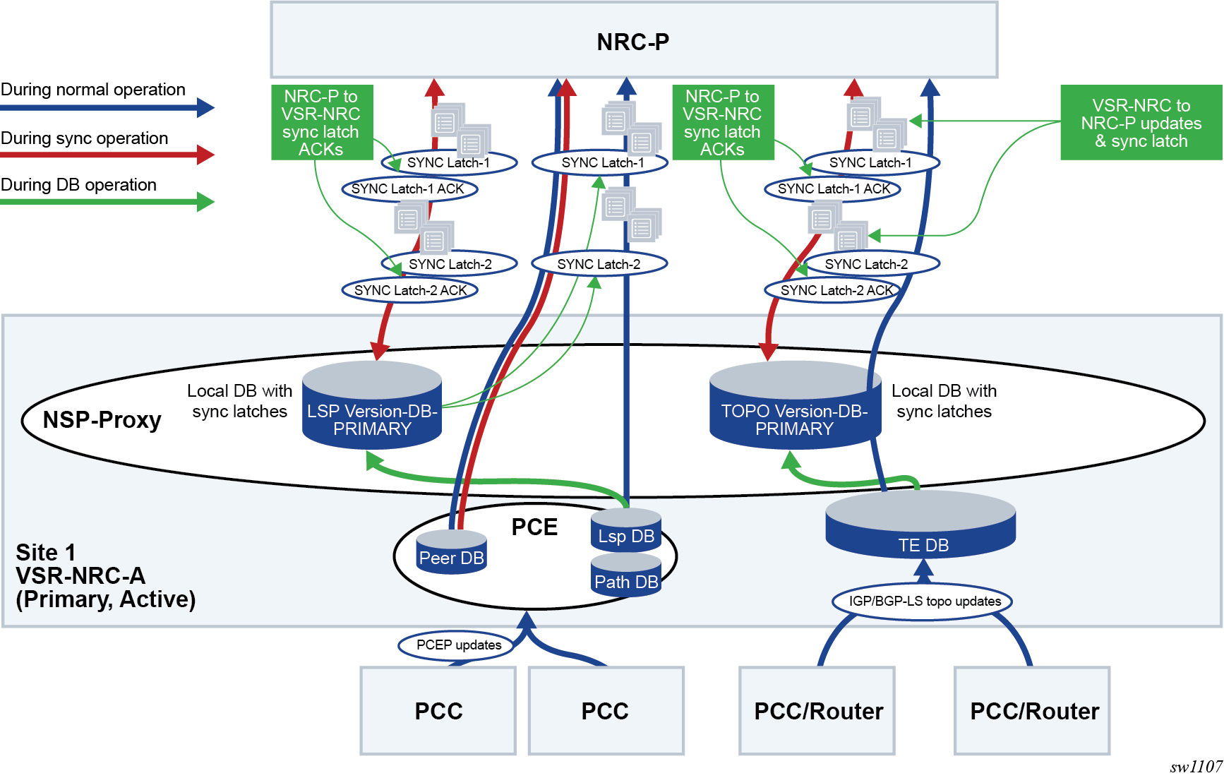
DB refers to the local TE-DB or LSP-DB maintained by the NSP-PROXY on the VSR-NRC.
The phrase Version-DB refers to the new copy of the same DB, TE-DB or LSP-DB, augmented with synchronization latches, and is used during the synchronization process to play back the records and latches to the NRC-P.
- Enhancements to DB maintenance in active VSR-NRC are follows:
- The active VSR-NRC, VSR-NRC-A or VAR-NRC-B (see VSR-NRC 1+1 redundancy), maintains a local copy of the database, referred to as Version-DB, for each record NSP-PROXY sends to NRC-P.
- Every 10 seconds, the NSP-PROXY also sends to NRC-P a message which contains a Latch Reference ID (LRID) only.
- The active VSR-NRC maintains a latch in Version-DB for each LRID sent to NRC-P. This latch is used to identify the start point for the SYNC_START message processing based on the LRID received from NRC-P.
- Enhancements to active VSR-NRC and NRC-P DB synchronization are as follows:
- After opening a PCEP or a BGP_LS service channel, the NRC-P in the primary site sends a SYNC_START with an LRID (empty for full sync) to the active VSR-NRC (VSR-NRC-A or VSR-NRC-B).
- The NSP-PROXY on the active VSR-NRC begins synchronization with the NRC-P of the Version-DB records, which include saved interleaved synchronization latches, from LRID specified in SYNC_START. An empty SYNC_START means the full content of the Version-DB is played back to NRC-P.
- After processing all the records up to the specified LRID, NRC-P sends an acknowledgement of that LRID to NSP-PROXY using SYNC_ACK.
- After initial synchronization, the NSP-PROXY on the active VSR-NRC resumes sending records from the main DB and inserts every 10 seconds an LRID message between the records it sends to NRC-P. The same stream of records interleaved with LRID messages is saved in the local Version-DB.
- As in the initial synchronization phase, NRC-P acknowledges back an LRID to NSP-PROXY using a SYNC_ACK after the complete processing of all the records up to that LRID.
The following diagram shows the enhancements to the cproto protobuf messages exchanged between VSR-NRC and NRC-P to provide full or partial synchronization of the TE-DB.
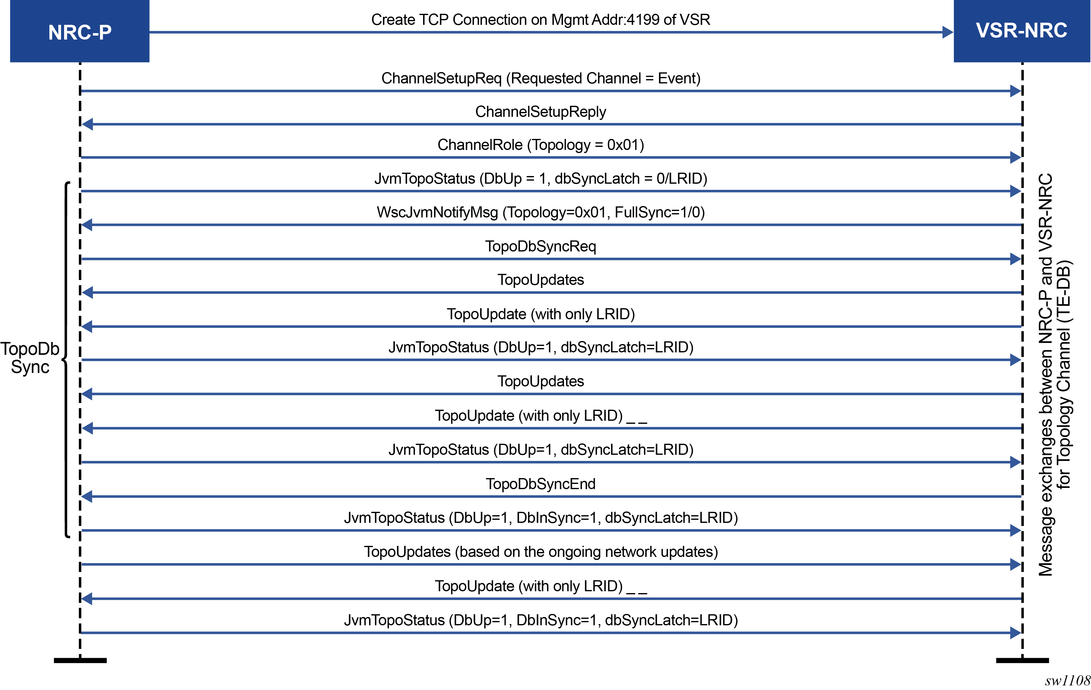
The following diagram shows the enhancements to the cproto protobuf messages exchanged between VSR-NRC and NRC-P to provide full or partial synchronization of the LSP-DB.
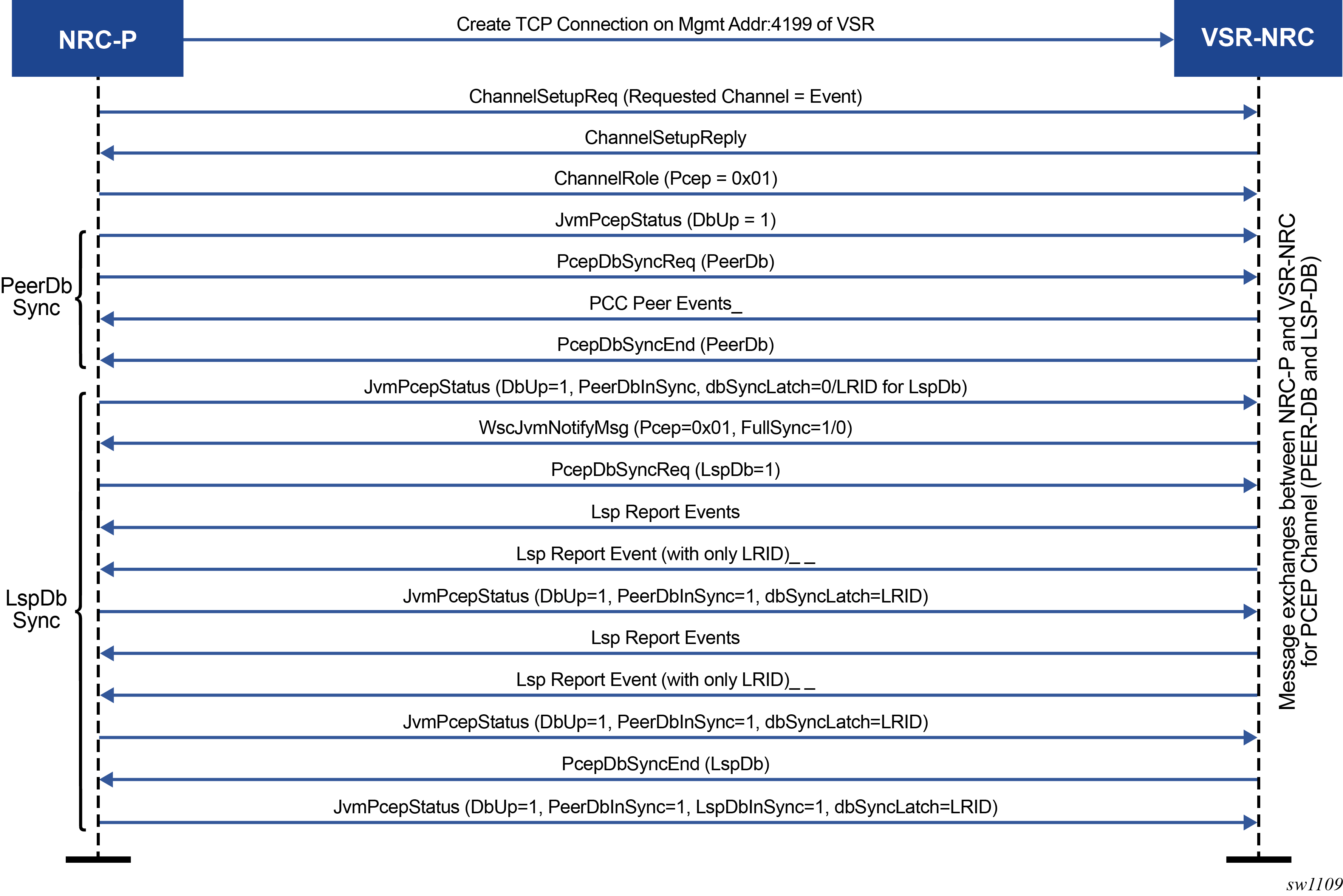
NSP and VSR-NRC PCE redundancy
This feature introduces resilience support to the PCE and PCC capabilities.
Overview of NSP ecosystem redundancy
The NSP ecosystem resilience consists of local, or single site, and remote, or dual site, redundancy mechanisms.
Redundancy in a single site deployment
The following diagram shows the NSP ecosystem and provisioning of redundancy within a single-site deployment.
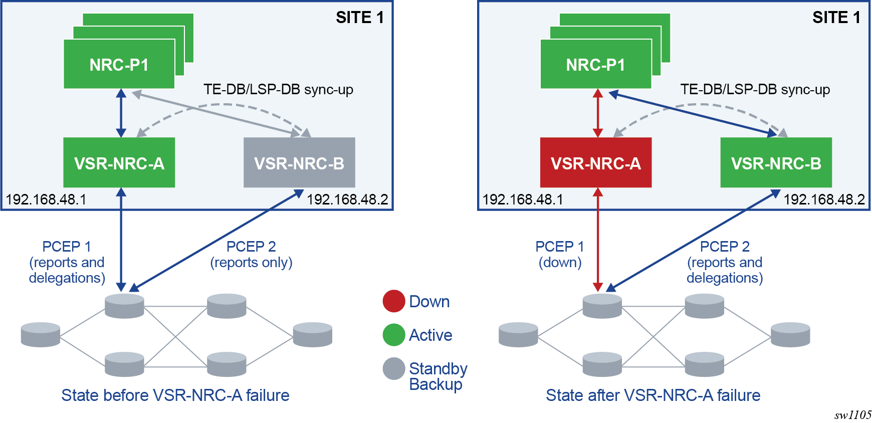
The NSP, where the NRC-P component resides, is protected by a cluster of three Virtual Machines (VMs). This local redundancy scheme elects one VM as the active and the other two VMs become standby backups. NSP must always be deployed in a cluster of three VMs.
The VSR-NRC module runs the integrated SR OS virtual SIM model (1 CPM+IOM VM) and can be deployed standalone.
The VSR-NRC can be protected with a VM cluster implementing the 1+1 redundancy scheme. The local redundancy provides for continuous full and partial synchronization of the TE-DB and LS-DB between the active VSR-NRC and the backup standby VSR-NRC, as well as with the local NRC-P.
The details of the VSR-NRC 1+1 single-site redundancy mechanism are provided in VSR-NRC 1+1 single-site redundancy.
Redundancy in a dual site deployment
The following diagram shows the NSP ecosystem and provisioning of redundancy within a dual-site deployment.
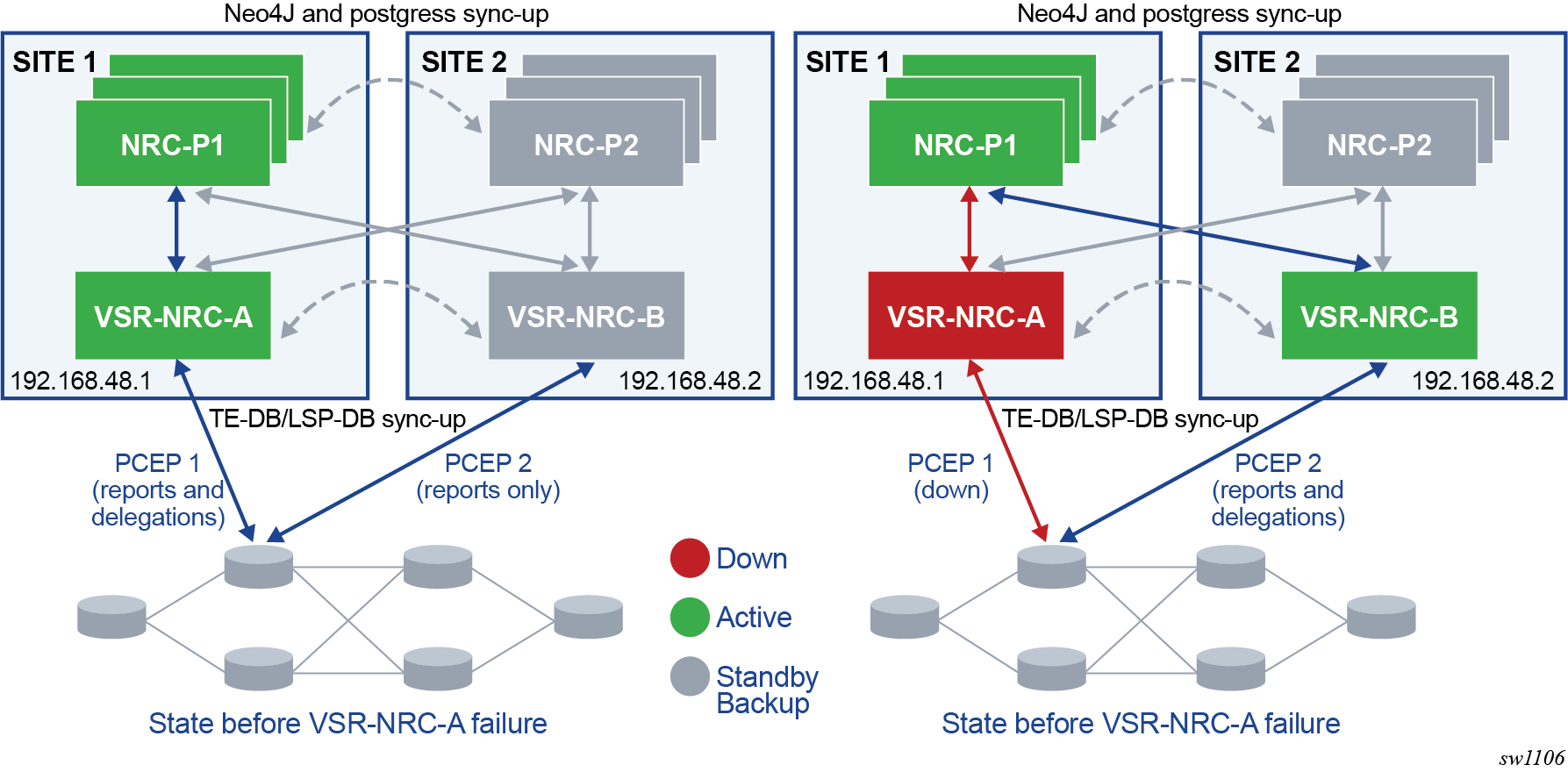
Both local and remote redundancy are deployed. The remote redundancy, sometimes referred to as Disaster Recovery (DR) or geo redundancy, consists of a primary site and a secondary backup site each with an NSP VM cluster and a single VSR-NRC VM.
A heartbeat protocol runs between the NSP clusters in the primary site and the standby backup sites.
The VSR-NRC connects to both the NRC-P within its own site and to the NRC-P in the remote site. A failover to the remote VSR-NRC occurs when the primary site fails entirely, when the primary NRC-P fails, and when the VSR-NRC only fails.
TE-DB and LSP-DB full and partial synchronization among the cluster of two VSR-NRCs improves the coverage of remote redundancy. In addition, the VSR-NRC 1+1 redundancy scheme is extended to the remote site. The details of the VSR-NRC 1+1 dual site redundancy are provided in VSR-NRC dual-site redundancy.
PCC and PCE configuration
The following CLI command enables the configuration on the PCC of a second PCEP session to the secondary backup PCE peer. A preference parameter value is used to indicate the primary or the secondary backup PCE peer role:
configure router pcep pcc peer ip-address [preference preference]
A maximum of two PCE peers are supported. The PCE peer that is not in overload is always selected by the PCC as the active PCE. However, if neither of the PCEs are signaling the overload state, the PCE with the higher numerical preference value is selected. In case of a tie, the PCE with the lower IP address is selected.
To change the value of the preference parameter, the peer must be deleted and recreated.
The following CLI command configures the routing preference to reach the PCE server. Use this command to configure in-band reachability for the PCE when the BOF autoconfiguration is enabled and a wide static route, for example, 0.0.0.0/0, is assigned through DHCP.
configure router pcep pcc peer ip-address route-preference {both | inband | outband}
The command options are:
- both
- specifies the use of the out-of-band routes in the management routing instance to reach the server before the in-band routes in the base routing instance. The default value is both.
- inband
- specifies the use of in-band routes only
- outband
- specifies the use of out-of-band routes only
The cproto channels are established through the management interface IPv4 or IPv6 address and open TCP port 4199 on both the primary and secondary VSR-NRCs.
In addition, the NRC-P always provides the active VSR-NRC acting as a cproto server with the system address of the mate VSR-NRC which to initiate the cproto channel to. The address is provided using the new Global Health and Notification cproto channel.
NRC-P provides a configuration for the primary VSR-NRC. This is the preferred active VSR-NRC. The other VSR-NRC is secondary. Nokia recommends setting the VSR-NRC co-located with the NRC-P as the primary VSR-NRC to take advantage of lowest latency and more reliable cproto channel.
In NSP ecosystem redundancy in dual-site deployment, the primary VSR-NRC in the local site is VSR-NRC-A and the secondary VSR-NRC in the remote site is VSR-NRC-B. The reverse configuration is performed in the remote site. With single-site VSR-NRC redundancy, both VSR-NRCs are local and either can be configured as the primary VSR-NRC.
NSP cluster redundancy
The following describes NSP cluster redundancy rules:
-
At each site, a master is elected among the cluster of three VMs. In a DR deployment, the cluster in one site is designated as the primary, meaning it is the preferred active cluster. The site is referred to as the primary site. The second cluster and site are referred to as secondary and therefore act as the standby backup cluster or site.
-
The application processes at the standby site are shut down, but the neo4j and other databases are synchronized with the primary active site.
-
Switching to the secondary standby site can be initiated manually or by using an automated approach stemming from the loss of heartbeat between the primary and standby sites.
-
When the NSP cluster at the primary active site is down (two out of three servers must be inactive, shut down, or failed), the heartbeat mechanism between the primary and standby NSP clusters fails after three timeouts. This initiates the active role at the secondary standby site.
-
When the NSP cluster at the primary site is back up, the heartbeat mechanism between the primary/standby and secondary/active NSP clusters is restored. The primary site can be restored to the active role manually. Automatic reversion to the primary NSP cluster is not supported.
VSR-NRC 1+1 redundancy
This feature implements support for the single site or local 1+1 redundancy of the VSR-NRC.
VSR-NRC 1+1 single-site redundancy
Single-site or local 1+1 redundancy of the VSR-NRC relies on extending the communication of the NSP-PROXY to synchronize the contents of the TE-DB and LSP-DB between the primary VSR-NRC (VSR-NRC-A) and the secondary VSR-NRC (VSR-NRC-B). This is supported by the cproto sync channel running between the two VSR-NRCs. The following diagram shows VSR-NRC 1+1 single-site redundancy.
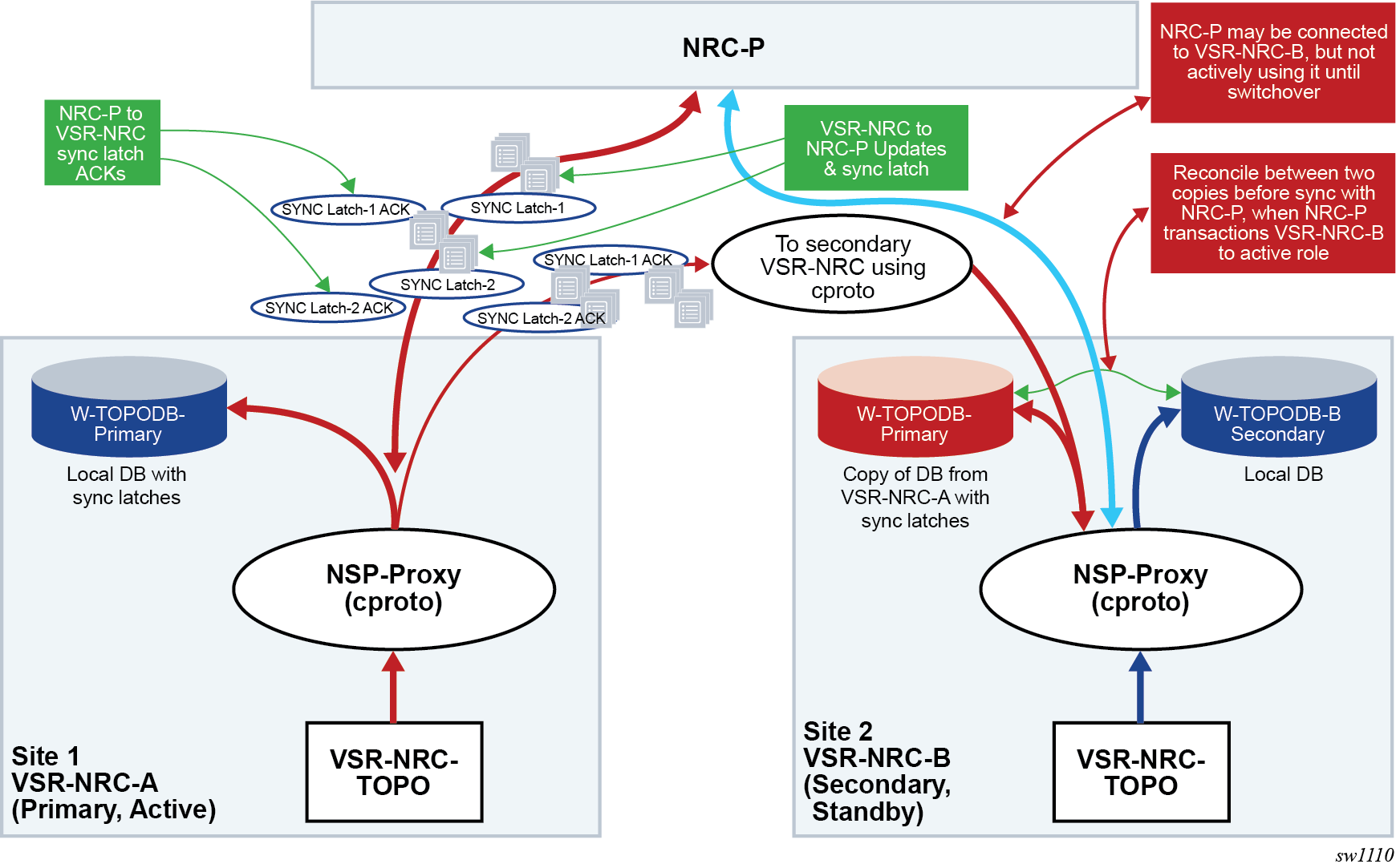
Initial establishment of active/standby VSR-NRC roles
- NRC-P performs up to three attempts at 10-second intervals to establish the global cproto
channel to the primary VSR-NRC (for example, VSR-NRC-A in the primary site). If
not successful, it performs another three attempts to the secondary VSR-NRC
(VSR-NRC-B in primary site). This process is continued cycling among the two
VSR-NRCs until the global channel is established to either VSR-NRC-A or
VSR-NRC-B, which then becomes the target active VSR-NRC. The cproto channel
establishment attempts continue to the other VSR-NRC which becomes the target
standby VSR-NRC.
This cproto channel establishment process is also followed when the global cproto channel to the active VSR-NRC goes down beginning always with an attempt to the primary VSR-NRC (VSR-NRC-A) and then onto the secondary VSR-NRC (VSR-NRC-B) and continues cycling between them until a channel is established.
- At successful global cproto channel establishment, the NRC-P sends a notify message (wscIsActive=TRUE, mateAddr, matePort) requesting a transition to active role from the VSR-NRC (VSR-NRC-A or VSR-NRC-B).
- When NRC-P also established the TOPO and PCEP cproto channels, the active VSR-NRC begins the partial database synchronization procedures to NRC-P, as mentioned in TE-DB and LSP-DB partial synchronization.
- When the reconcile process is complete, the active VSR-NRC acknowledges the NRC-P by sending a notify reply message (notifyReply=TRUE).
- The active VSR-NRC attempts to establish a cproto sync channel to the mate VSR-NRC. After it is successfully established, it begins the full or partial database synchronization procedures to the mate VSR-NRC following the procedures, as mentioned in TE-DB and LSP-DB partial synchronization.
- After the global cproto channel to the target standby VSR-NRC is established, NRC-P sends a notify message (wscIsActive=FALSE, mateAddr, matePort) requesting transition to a standby role. The target standby VSR-NRC acknowledges by sending a notify reply message (notifyReply=TRUE). No database synchronization occurs between the standby VSR-NRC and the NRC-P.
- The standby VSR-NRC maintains a copy of the mate active VSR-NRC database and independently builds its own database using BGP-LS and PCEP peerings with the network.
- When the active and standby roles have been assigned by the NRC-P, the primary and secondary VSR-NRCs keep that role until further notice from NRC-P. The roles are not affected by the state of the cproto sync channel.
Failover to backup VSR-NRC
- If the active VSR-NRC fails, the NRC-P detects it when the global cproto channel goes down.
The NRC-P uses a keepalive timer of 60 seconds and a multiplier of 2.2 for a total keepalive timeout of 132 seconds.
At keepalive timeout, NRC-P determines that the channel is idle and closes it. NRC-P also closes the TOPO and PCEP cproto channels, if they are not already down.
- Next, the NRC-P begins its cproto establishment cycle as detailed in Initial establishment of active/standby VSR-NRC roles. If the failed VSR-NRC is the
primary VSR-NRC (VSR-NRC-A in the primary site), three attempts are performed to
bring the global cproto channel back up. If the global cproto channel is
successfully restored, the primary VSR-NRC remains the target active VSR-NRC. If
not, three attempts are performed to the secondary VSR-NRC (VSR-NRC-B) and so
on.Note: It can take up to 162 seconds for the NRC-P to switch to the secondary standby VSR-NRC. This includes the keepalive idle time of 132 seconds plus up to three attempts of 10-second intervals to establish the global cproto channel, three unsuccessful attempts to primary VSR-NRC and one successful attempt to the secondary VSR-NRC. If the user reboots the primary VSR-NRC (VSR-NRC-A) while it is active, it may come back up faster, and therefore, it remains the target active VSR-NRC and NRC-P does not switch to secondary VSR-NRC (VSR-NRC-B).
- When the global cproto channel is up to the target active VSR-NRC, either the primary or secondary VSR-NRC, NRC-P sends a notify message requesting active role and providing the IP address for the mate VSR-NRC (wscIsActive=TRUE, mateAddr, matePort).
-
The target active VSR-NRC begins the transition to the active role by flapping the cproto sync session to the mate VSR-NRC, if not already down. Then it begins reconciling the local copy of the mate databases with its own network-learned databases. The common records only have a difference in the setting of the Delegate bit in the PCEP Report messages.
The following reconcile process is followed:-
Common records of the local database are carried over with setting of the Delegate bit in the PCEP Report messages and with the LRID information from the mate database.
-
Records in the mate database which are not reconciled with the local database are deleted.
-
Records in the local database which are not reconciled with the mate database are always carried over.
Common records of the local database are preferred over those of the mate copy database except for the LRID. After the reconcile process is complete, the now newly active VSR-NRC destroys the mate copy database and acknowledges the NRC-P by sending a notify reply message (notifyReply=TRUE).
-
- The newly active VSR-NRC begins the partial database synchronization procedures to NRC-P as described in TE-DB and LSP-DB partial synchronization. The newly active VSR-NRC stops accepting new records from its own TE-DB and LSP-DB until after it completes the reconcile between the mate copy databases and its local databases and completes the partial synchronization with NRC-P.
- The newly active VSR-NRC notifies the local PCE process to set the PCEP overload to OFF and to start an overload timer, hard-coded to 10 minutes, for each PCEP session. At the receipt of the first PCEP redelegation from a PCC, VSR-NRC stops the timer for that PCC and sends a PCC ready message to NRC-P, which can then begin sending update messages to that PCC. If the overload timer expires before receiving a PCEP redelegation message, the newly active VSR-NRC clears all delegations of the corresponding PCC toward NRC-P.
- The newly active VSR-NRC attempts to establish a cproto channel to the mate VSR-NRC. After successfully establishing a channel, it begins the full or partial database synchronization procedures to the mate VSR-NRC following similar procedures as mentioned in TE-DB and LSP-DB partial synchronization.
Recovery of the failed VSR-NRC
- The recovered VSR-NRC assumes the role of None, meaning it is neither active nor standby, until the global channel is successfully established from the NRC-P. In this state, it does not accept a cproto sync channel from its mate VSR-NRC.
- After successfully opening a global cproto channel, NRC-P sends a notify message (wscIsActive=FALSE, mateAddr, matePort) to the recovered VSR-NRC to request transition to standby role.
- The recovered VSR-NRC then accepts the cproto sync channel from its mate and prepares the mate copy DBs to accept the updates from its mate VSR-NRC.
- VSR-NRC sends to NRC-P a notify reply message (notifyReply=TRUE) to accept the standby role assigned by NSP.
- The newly standby VSR-NRC notifies the local PCE process to set the PCEP overload to ON.
- NRC-P keeps this global cproto channel alive by sending KAs at regular intervals. No other service cproto channel is created while this VSR-NRC is in standby role.
- NRC-P does not automatically revert the active role to the recovered VSR-NRC. A manual reversion procedure is supported. See Manual switchover to the mate VSR-NRC for the reversion procedure.
Manual switchover to the mate VSR-NRC
The NRC-P provides an API to perform a manual switchover to the mate VSR-NRC. This could be used, for example, to revert the active role back to a recovered primary VSR-NRC.
- NRC-P sends a notify message (wscIsActive=FALSE, mateAddr, matePort) over the global channel to currently active VSR-NRC to request transition to standby role.
- The currently active VSR-NRC shuts down the cproto sync channel to its mate and prepares the mate copy DBs to accept the updates from its mate VSR-NRC.
- The currently active VSR-NRC sends to NRC-P a notify reply message (notifyReply=TRUE) to accept the standby role requested.
- NRC-P then follows the steps in Initial establishment of active/standby VSR-NRC roles to transition the currently standby VSR-NRC to active role.
VSR-NRC dual-site redundancy
The behavior of dual-site redundancy follows the single site redundancy procedures because only the active NRC-P can establish cproto channels to the pair of primary and secondary VSR-NRCs.
When the NRC-P in the secondary site becomes active, it attempts to establish a cproto global channel to both primary and secondary VSR-NRCs. Nokia recommends configuring the local VSR-NRC (VSR-NRC-B) as the primary VSR-NRC in the secondary site.
Global health and notification cproto channel
The VSR-NRC 1+1 redundancy features introduces a global channel between each VSR-NRC and the NRC-P for exchanging channel health and notification messages that are not application-specific.
The following diagram shows the sequence of messages to establish the global health and notification channel as well as the sequence of messages used for establishing the VSR-NRC role of active or standby.
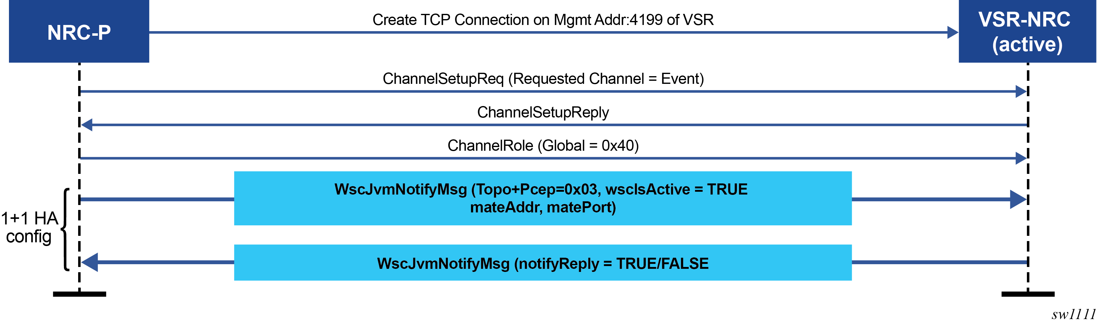
PCE southbound and PCC behavior
PCE southbound behavior
The following describes VSR-NRC PCE redundancy rules:
-
steady state behavior
-
The PCC establishes a PCEP session to each of the primary active VSR-NRC and secondary standby VSR-NRC. The secondary standby VSR-NRC is either in the primary site with single site redundancy or at the secondary site with dual site redundancy, however, the secondary standby VSR-NRC sets PCEP sessions with the PCCs in the overload state. The VSR-NRC enters this PCEP overload state when its upstream cproto session to the NSP cluster is down, or is being instructed by the NRC-P to enter the standby state as described in VSR-NRC 1+1 redundancy.
-
The VSR-NRC acting as a PCE signals the overload state to the PCCs in a PCEP notification message. While in the overload state, the VSR-NRC PCE accepts reports (PCRpt) without delegation but rejects requests (PCReq) and reject reports (PCRpt) with delegation. The VSR-NRC PCE also does not originate initiate messages (PCInitiate) and update messages (PCUpd).
-
The secondary standby VSR-NRC maintains its BGP and IGP peerings with the network and updates its TE database as a result of any network topology changes.
-
-
primary active NSP cluster failure
When the NSP cluster at the primary active site is down (two out of three servers must be inactive, shut down, or failed), the heartbeat mechanism between the primary active and secondary standby NSP clusters fails. This initiates the NSP cluster activity at the secondary standby site.
The following are the procedures on the VSR-NRC:
-
The primary VSR-NRC detects cproto global channel failure and puts all its PCEP sessions to the PCCs into the overload state.
-
The NRC-P in the NSP cluster at the secondary site follows the procedures in VSR-NRC 1+1 redundancy to transition the secondary VSR-NRC into active state.
-
The VSR-NRC at the primary site must also return the delegation of all LSPs back to the PCCs by sending an empty LSP Update Request that has the Delegate flag set to 0 in accordance with RFC 8231. To accommodate third party PCE implementations which may not return delegations, each PCC concurrently revokes the delegation of its LSPs from the primary VSR-NRC PCE. This allows the PCCs to delegate all eligible LSPs, including PCE-initiated LSPs, to the PCE function in the VSR-NRC at the secondary site. If the entire primary active site fails, the PCE side procedure in this step does not apply.
-
-
VSR-NRC complex failure at the primary site (NSP server is still up)
A VSR-NRC complex failure at the primary active NSP triggers the failover to backup VSR-NRC procedures in VSR-NRC 1+1 redundancy.
PCC behavior
The following describes PCC rules with PCE redundancy:
-
PCCs can establish upstream PCEP sessions with at most two VSR-NRC PCEs.
-
Each upstream session has a preference that takes effect when both upstream PCEP sessions are successfully established. The PCE peer that is not in overload is always selected by the PCC as the active PCE. However, if neither of the PCEs are signaling the overload state, the PCE with the higher numerical preference value is selected, and in case of a tie, the PCE with the lower IP address is selected.
-
In the steady state, because one upstream VSR-NRC PCE is in overload, only one PCEP session is active. The PCCs send request messages (PCReq) active VSR-NRC PCE only. Similarly, the PCCs delegate an LSP using a report message (PCRpt) with the Delegate flag set to the active VSR-NRC PCE only. PCRpt messages are sent with the Delegate flag clear to the secondary standby VSR-NRC PCE in overload.
-
If the current active PCEP session signals overload state, the PCC selects the other PCE as the active PCE as long as the corresponding PCEP session is not in overload. Any new path request message (PCReq) or path report message (PCRpt), with the Delegate flag set, is sent to the new PCE.
The PCE in overload returns the delegation of all existing LSPs back to this PCC by sending an empty LSP Update message that has the Delegate flag set as in accordance with RFC 8231. To accommodate third party PCE implementations which may not return delegations, each PCC concurrently revokes the delegation of its LSPs from the current PCE. The PCC delegates these LSPs to the new active PCE by sending a path report (PCRpt) message with the Delegate flag set.
-
If the current active PCEP session goes operationally down, the PCC starts the redelegation timer (default 90 seconds) and state timer (default 180 seconds).
-
If the PCEP session is restored before the redelegation timer expires, no delegation change is performed and the LSP state is maintained.
-
Upon expiration of the redelegation timer, the PCC looks for the other PCEP session and, if not in overload, it immediately delegates the LSPs to the newly active PCE. If the new PCE accepts the delegation, the LSP state is maintained.
-
If the PCEP session does not recover before the redelegation timer expires and the PCC fails to find another active PCEP session, then by default the PCC clears the LSP state of PCE-initiated LSPs after state timer expiry. The PCC deletes the PCE-initiated LSPs and releases all their resources. A configuration option of the redelegation timer CLI command allows the user to keep the state of the pce-initiated LSPs instead. The PCC does not clear the state of PCC-initiated LSPs; however, the user can do this by deleting the configuration.
-
VSR-NRC ROM
The VSR-NRC supports originating routes on behalf of the NRC-P toward route reflectors or BGP routers in the network. One of the most common applications is origination using BGP of SR policy candidate paths. The VSR-NRC ROM implements this capability. SR policy candidate paths are advertised as sr-policy-ipv4 BGP routes.
NRC-P sends SR policy candidate path routes to both the active and secondary backup VSR-NRCs using the cproto ROM channel. NRC-P tracks the last route sent to each VSR-NRC separately. This tracking includes whether the last route was route ADD, DELETE, or MODIFY.
The VSR-NRC uses a cache to store SR policy route origination requests from the NRC-P. Upon receiving an SR policy route origination request, the VSR-NRC submits the SR policy route ADD or DELETE to the SR policy manager. ROM handles route ADD as a route MODIFY when there is already a record of the policy candidate path in its cache. The interface from ROM to the SR policy manager database uses <color, endpoint, headend> as the key in the lookup to identify the SR policy and uses <preference, rd> as a parameter to identify a specific candidate path of the SR policy.
The SR policy manager in VSR-NRC saves and organizes all submitted SR policy routes according to owner. Owner STATIC is used for routes submitted using the CLI and the management interface, owner BGP is used for routes submitted using the BGP control plane, and owner NSP is used for routes submitted by ROM.
When a cproto ROM channel goes down, ROM starts a timer with a value equal to the cproto keep alive expiry timeout value of 60 × 2.2 seconds. When this timer expires, ROM scans through all NSP owner records in its route cache and requests the SR policy manager database to flush them. As a result, the BGP module is called upon to withdraw the corresponding NLRIs from the BGP peers in the network.
Because NRC-P switches to the backup VSR-NRC when the cproto ROM channel goes down, the flush operation is necessary. However, if the originally active VSR-NRC is still up, it may remain the preferred source for the routes selected by the BGP peer routers in the network while its own SR policy manager routes are out-of-date with those of the NRC-P.
The NRC-P also supports sending an explicit flush request while the cproto ROM channel is up. This is used to clear stale route entries caused by multiple redundancy switchover operations.
When a cproto ROM channel comes back up, ROM in VSR-NRC sends a Notify message to NRC-P to indicate that the route cache and SR policy manager database were flushed. Subsequently, NRC-P checks the VSR-NRC uptime. If it is lower than the downtime of the cproto ROM channel to the VSR-NRC, NRC-P assumes the VSR-NRC rebooted and sends the full SR policy route database to ROM (full synchronization). If the VSR-NRC uptime is higher than the downtime of the cproto ROM channel to the VSR-NRC, NRC-P sends only the newer records (partial synchronization).
Configuring and operating RSVP-TE LSP with PCEP
This section provides information about configuring and operating RSVP-TE LSP with PCEP using CLI.
The following describes the detailed configuration of an inter-area RSVP-TE LSP with both a primary path and a secondary path. The network uses IS-IS with the backbone area in Level 2 and the leaf areas in Level 1. Topology discovery is learned by NRC-P using BGP-LS.
The LSP uses an admin-group constraint to keep the paths of the secondary and primary link disjoint in the backbone area. The LSP is PCE-controlled but also has path-computation-method pce enabled so the initial path, and any MBB path, is also computed by PCE.
The NSP and SR OS load versions used to produce this example are:
For NSP, NSP-2.0.3-rel.108
For PCE SR OS, TiMOS-B-0.0.W129
For PCC, TiMOS-B-0.0.I4902
The following diagram shows a multi-level IS-IS topology in the NSP GUI:
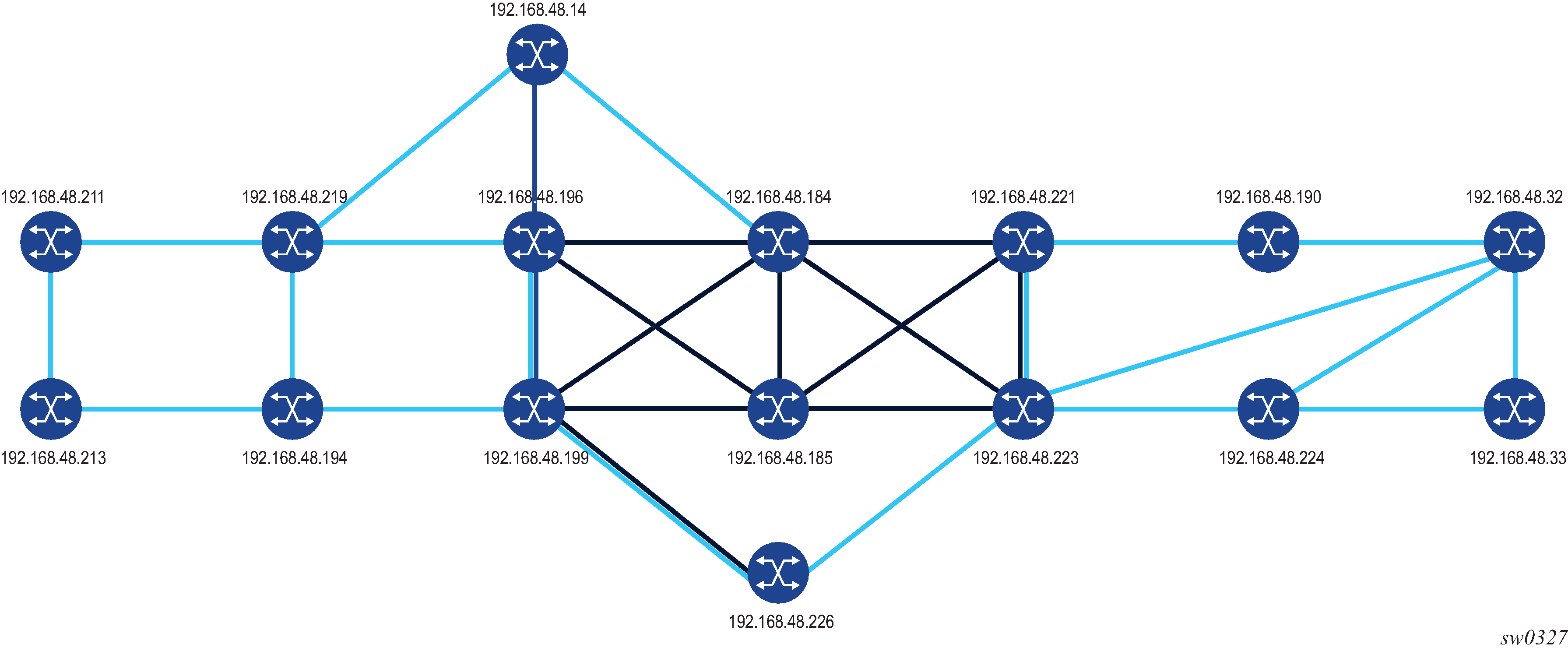
Configuration and show command output of the PCEP on the PCE node and the PCC node
*A:PCE Server 226>config>router>pcep>pce# info
----------------------------------------------
            local-address 192.168.48.226
            no shutdown
----------------------------------------------
*A:Reno 194>config>router>pcep>pcc# info
----------------------------------------------
            peer 192.168.48.226
                no shutdown
            exit
            no shutdown
----------------------------------------------

*A:PCE Server 226>config>router>pcep>pce# show router pcep pce status
===============================================================================
Path Computation Element Protocol (PCEP) Path Computation Element (PCE) Info
===============================================================================
Admin Status           : Up              Oper Status          : Up
Unknown Msg Limit      : 10 msg/min
Keepalive Interval     : 30 seconds      DeadTimer Interval   : 120 seconds
Capabilities List      : stateful-delegate stateful-pce segment-rt-path
Local Address          : 192.168.48.226
PCE Overloaded         : false
-------------------------------------------------------------------------------
PCEP Path Computation Element (PCE) Peer Info
-------------------------------------------------------------------------------
Peer                       Sync State             Oper Keepalive/Oper DeadTimer
-------------------------------------------------------------------------------
192.168.48.190:4189        done                   30/120
192.168.48.194:4189        done                   30/120
192.168.48.198:4189        done                   30/120
192.168.48.199:4189        done                   30/120
192.168.48.219:4189        done                   30/120
192.168.48.221:4189        done                   30/120
192.168.48.224:4189        done                   30/120
-------------------------------------------------------------------------------
===============================================================================

*A:Reno 194# show router pcep pcc status
=======================================================================
Path Computation Element Protocol (PCEP) Path Computation Client (PCC) Info
=======================================================================
Admin Status           : Up              Oper Status          : Up
Unknown Msg Limit      : 10 msg/min
Keepalive Interval     : 30 seconds      DeadTimer Interval   : 120 seconds
Capabilities List      : stateful-delegate stateful-pce segment-rt-path
Address                : 192.168.48.194
Report Path Constraints: True
-----------------------------------------------------------------------
PCEP Path Computation Client (PCC) Peer Info
-----------------------------------------------------------------------
Peer                       Admin State/Oper State Oper Keepalive/Oper DeadTimer
-----------------------------------------------------------------------
192.168.48.226             Up/Up                  30/120
-----------------------------------------------------------------------
=======================================================================

*A:Reno 194# show router pcep pcc lsp-db
=======================================================================
PCEP Path Computation Client (PCC) LSP Update Info
=======================================================================
PCEP-specific LSP ID: 11
LSP ID              : 14378             LSP Type            : rsvp-p2p
Tunnel ID           : 1                 Extended Tunnel Id  : 192.168.48.194
LSP Name            : From Reno to Atlanta RSVP-TE::primary_empty
Source Address      : 192.168.48.194    Destination Address : 192.168.48.224
LSP Delegated       : True              Delegate PCE Address: 192.168.48.226
Oper Status         : active
-----------------------------------------------------------------------
PCEP-specific LSP ID: 12
LSP ID              : 14380             LSP Type            : rsvp-p2p
Tunnel ID           : 1                 Extended Tunnel Id  : 192.168.48.194
LSP Name            : From Reno to Atlanta RSVP-TE::secondary_empty
Source Address      : 192.168.48.194    Destination Address : 192.168.48.224
LSP Delegated       : True              Delegate PCE Address: 192.168.48.226
Oper Status         : up
=======================================================================
Configuration and show command output of BGP on the PCE node and the ABR node-to-learn topology using the BGP-LS NLRI family
*A:PCE Server 226>config>router>bgp# info
----------------------------------------------
            family bgp-ls
            min-route-advertisement 1
            link-state-export-enable
            group "IBGP_L2"
                family bgp-ls
                peer-as 65000
                neighbor 192.168.48.198
                exit
                neighbor 192.168.48.199
                exit
                neighbor 192.168.48.221
                exit
            exit
            no shutdown
----------------------------------------------

*A:Chicago 221>config>router>bgp# info
----------------------------------------------
            min-route-advertisement 1
            advertise-inactive
            link-state-import-enable
            group "IBGP_L2"
                family bgp-ls
                peer-as 65000
                neighbor 192.168.48.226
                exit
            exit
            no shutdown
----------------------------------------------

*A:PCE Server 226# show router bgp summary
===============================================================================
 BGP Router ID:192.168.48.226    AS:65000       Local AS:65000
===============================================================================
BGP Admin State         : Up          BGP Oper State              : Up
Total Peer Groups       : 1           Total Peers                 : 3
Total BGP Paths         : 182         Total Path Memory           : 44896
Total IPv4 Remote Rts   : 0           Total IPv4 Rem. Active Rts  : 0
Total McIPv4 Remote Rts : 0           Total McIPv4 Rem. Active Rts: 0
Total McIPv6 Remote Rts : 0           Total McIPv6 Rem. Active Rts: 0
Total IPv6 Remote Rts   : 0           Total IPv6 Rem. Active Rts  : 0
Total IPv4 Backup Rts   : 0           Total IPv6 Backup Rts       : 0
Total Supressed Rts     : 0           Total Hist. Rts             : 0
Total Decay Rts         : 0
Total VPN Peer Groups   : 0           Total VPN Peers             : 0
Total VPN Local Rts     : 0
Total VPN-IPv4 Rem. Rts : 0           Total VPN-IPv4 Rem. Act. Rts: 0
Total VPN-IPv6 Rem. Rts : 0           Total VPN-IPv6 Rem. Act. Rts: 0
Total VPN-IPv4 Bkup Rts : 0           Total VPN-IPv6 Bkup Rts     : 0
Total VPN Supp. Rts     : 0           Total VPN Hist. Rts         : 0
Total VPN Decay Rts     : 0
Total L2-VPN Rem. Rts   : 0           Total L2VPN Rem. Act. Rts   : 0
Total MVPN-IPv4 Rem Rts : 0           Total MVPN-IPv4 Rem Act Rts : 0
Total MDT-SAFI Rem Rts  : 0           Total MDT-SAFI Rem Act Rts  : 0
Total MSPW Rem Rts      : 0           Total MSPW Rem Act Rts      : 0
Total RouteTgt Rem Rts  : 0           Total RouteTgt Rem Act Rts  : 0
Total McVpnIPv4 Rem Rts : 0           Total McVpnIPv4 Rem Act Rts : 0
Total McVpnIPv6 Rem Rts : 0           Total McVpnIPv6 Rem Act Rts : 0
Total MVPN-IPv6 Rem Rts : 0           Total MVPN-IPv6 Rem Act Rts : 0
Total EVPN Rem Rts      : 0           Total EVPN Rem Act Rts      : 0
Total FlowIpv4 Rem Rts  : 0           Total FlowIpv4 Rem Act Rts  : 0
Total FlowIpv6 Rem Rts  : 0           Total FlowIpv6 Rem Act Rts  : 0
Total LblIpv4 Rem Rts   : 0           Total LblIpv4 Rem. Act Rts  : 0
Total LblIpv6 Rem Rts   : 0           Total LblIpv6 Rem. Act Rts  : 0
Total LblIpv4 Bkp Rts   : 0           Total LblIpv6 Bkp Rts       : 0
Total Link State Rem Rts: 271         Total Link State Rem. Act Rts: 0
===============================================================================
BGP Summary
===============================================================================
Legend : D - Dynamic Neighbor
===============================================================================
Neighbor
Description
                   AS PktRcvd InQ  Up/Down   State|Rcv/Act/Sent (Addr Family)
                      PktSent OutQ
-------------------------------------------------------------------------------
192.168.48.198
               65000        0    0 02h42m56s Active
                            0    0
192.168.48.199
               65000      503    0 02h42m56s 76/0/0 (LinkState)
                          328    0
192.168.48.221
               65000      519    0 02h42m56s 195/0/0 (LinkState)
                          328    0
-------------------------------------------------------------------------------

*A:PCE Server 226# show router bgp routes bgp-ls hunt link
===============================================================================
 BGP Router ID:192.168.48.226    AS:65000       Local AS:65000
===============================================================================
 Legend -
 Status codes  : u - used, s - suppressed, h - history, d - decayed, * - valid
                 l - leaked, x - stale, > - best, b - backup, p - purge
 Origin codes  : i - IGP, e - EGP, ? - incomplete
===============================================================================
BGP-LS Link NLRIs
===============================================================================
-------------------------------------------------------------------------------
RIB In Entries
-------------------------------------------------------------------------------
Network:
 Type          : LINK-NLRI
 Protocol      : ISIS Level-2           Identifier     : 0xa
 Local Node descriptor:
  Autonomous System  : 0.0.253.232
  Link State Id      : 10
  IGP Router Id      : 0x38120048184
 Remote Node descriptor:
  Autonomous System  : 0.0.253.232
  Link State Id      : 10
  IGP Router Id      : 0x38120048223
 Link descriptor:
  IPV4 Interface Addr: 10.0.14.184
  IPV4 Neighbor Addr : 10.0.14.223
Nexthop        : 192.168.48.199
From           : 192.168.48.199
Res. Nexthop   : 0.0.0.0
Local Pref.    : 100                    Interface Name : NotAvailable
Aggregator AS  : None                   Aggregator     : None
Atomic Aggr.   : Not Atomic             MED            : None
AIGP Metric    : None
Connector      : None
Community      : No Community Members
Cluster        : No Cluster Members
Originator Id  : None                   Peer Router Id : 192.168.48.199
Flags          : Valid  Best  IGP
Route Source   : Internal
AS-Path        : No As-Path
Route Tag      : 0
Neighbor-AS    : N/A
Orig Validation: N/A
Source Class   : 0                      Dest Class     : 0
Add Paths Send : Default
Last Modified  : 02h27m50s
-------------------------------------------------------------------------------
Link State Attribute TLVs :
 Administrative group (color) : 0x0
 Maximum link bandwidth : 100000 Kbps
 Max. reservable link bandwidth : 100000 Kbps
 Unreserved bandwidth0 : 100000 Kbps
 Unreserved bandwidth1 : 100000 Kbps
 Unreserved bandwidth2 : 100000 Kbps
 Unreserved bandwidth3 : 100000 Kbps
 Unreserved bandwidth4 : 100000 Kbps
 Unreserved bandwidth5 : 100000 Kbps
 Unreserved bandwidth6 : 100000 Kbps
 Unreserved bandwidth7 : 100000 Kbps
 TE Default Metric : 100
 IGP Metric : 100
 Adjacency Segment Identifier (Adj-SID) :       flags 0x30 weight 0 sid 262136
-------------------------------------------------------------------------------
Network:
 Type          : LINK-NLRI
 Protocol      : ISIS Level-2           Identifier     : 0xa
 Local Node descriptor:
  Autonomous System  : 0.0.253.232
  Link State Id      : 10
  IGP Router Id      : 0x38120048184
 Remote Node descriptor:
  Autonomous System  : 0.0.253.232
  Link State Id      : 10
  IGP Router Id      : 0x38120048223
 Link descriptor:
  IPV4 Interface Addr: 10.0.14.184
  IPV4 Neighbor Addr : 10.0.14.223
Nexthop        : 192.168.48.221
From           : 192.168.48.221
Res. Nexthop   : 0.0.0.0
Local Pref.    : 100                    Interface Name : NotAvailable
Aggregator AS  : None                   Aggregator     : None
Atomic Aggr.   : Not Atomic             MED            : None
AIGP Metric    : None
Connector      : None
Community      : No Community Members
Cluster        : No Cluster Members
Originator Id  : None                   Peer Router Id : 192.168.48.221
Flags          : Valid  IGP
TieBreakReason : OriginatorID
Route Source   : Internal
AS-Path        : No As-Path
Route Tag      : 0
Neighbor-AS    : N/A
Orig Validation: N/A
Source Class   : 0                      Dest Class     : 0
Add Paths Send : Default
Last Modified  : 02h27m54s
-------------------------------------------------------------------------------
Link State Attribute TLVs :
 Administrative group (color) : 0x0
 Maximum link bandwidth : 100000 Kbps
 Max. reservable link bandwidth : 100000 Kbps
 Unreserved bandwidth0 : 100000 Kbps
 Unreserved bandwidth1 : 100000 Kbps
 Unreserved bandwidth2 : 100000 Kbps
 Unreserved bandwidth3 : 100000 Kbps
 Unreserved bandwidth4 : 100000 Kbps
 Unreserved bandwidth5 : 100000 Kbps
 Unreserved bandwidth6 : 100000 Kbps
 Unreserved bandwidth7 : 100000 Kbps
 TE Default Metric : 100
 IGP Metric : 100
 Adjacency Segment Identifier (Adj-SID) :       flags 0x30 weight 0 sid 262136
-------------------------------------------------------------------------------
The following diagram shows primary and secondary RSVP-TE LSP paths in the NSP GUI.
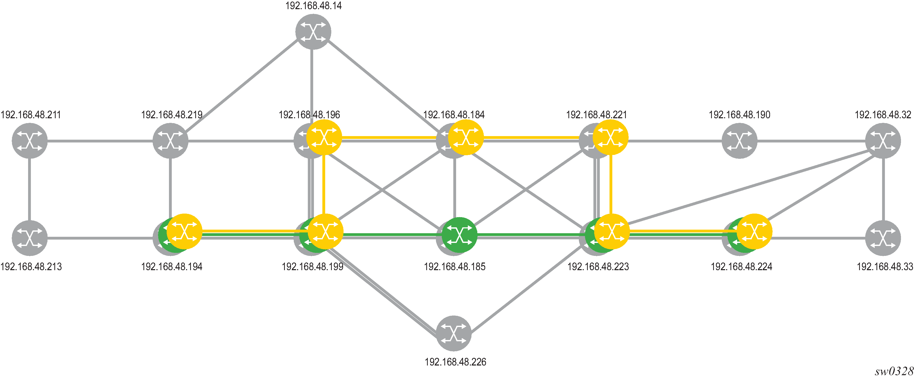
Configuration and show command output of the MPLS on the PCC node
*A:Reno 194>config>router>mpls>lsp# info
----------------------------------------------
                to 192.168.48.224
                egress-statistics
                    shutdown
                exit
                fast-reroute facility
                    no node-protect
                exit
                path-computation-method pce
                pce-report enable
                pce-control
                revert-timer 1
                primary "primary_empty"
                    exclude "top"
                    bandwidth 10
                exit
                secondary "secondary_empty"
                    standby
                    exclude "bottom"
                    bandwidth 5
                exit
                no shutdown
----------------------------------------------

*A:Reno 194# show router mpls lsp "From Reno to Atlanta RSVP-TE" path detail
===============================================================================
MPLS LSP From Reno to Atlanta RSVP-TE Path  (Detail)
===============================================================================
Legend :
    @ - Detour Available              # - Detour In Use
    b - Bandwidth Protected           n - Node Protected
    s - Soft Preemption
    S - Strict                        L - Loose
    A - ABR
===============================================================================
-------------------------------------------------------------------------------
LSP From Reno to Atlanta RSVP-TE Path primary_empty
-------------------------------------------------------------------------------
LSP Name         : From Reno to Atlanta RSVP-TE
Path LSP ID      : 14382
From             : 192.168.48.194       To                   : 192.168.48.224
Admin State      : Up                   Oper State           : Up
Path Name        : primary_empty        Path Type            : Primary
Path Admin       : Up                   Path Oper            : Up
Out Interface    : 1/1/1                Out Label            : 262094
Path Up Time     : 0d 00:00:22          Path Down Time       : 0d 00:00:00
Retry Limit      : 0                    Retry Timer          : 30 sec
Retry Attempt    : 0                    Next Retry In        : 0 sec
BFD Template     : None                 BFD Ping Interval    : 60
BFD Enable       : False
Adspec           : Disabled             Oper Adspec          : Disabled
CSPF             : Enabled              Oper CSPF            : Enabled
Least Fill       : Disabled             Oper LeastFill       : Disabled
FRR              : Enabled              Oper FRR             : Enabled
FRR NodeProtect  : Disabled             Oper FRR NP          : Disabled
FR Hop Limit     : 16                   Oper FRHopLimit      : 16
FR Prop Admin Gr*: Disabled             Oper FRPropAdmGrp    : Disabled
Propogate Adm Grp: Disabled             Oper Prop Adm Grp    : Disabled
Inter-area       : False
PCE Updt ID      : 0
PCE Report       : Enabled              Oper PCE Report      : Enabled
PCE Control      : Enabled              Oper PCE Control     : Enabled
PCE Compute      : Enabled
Neg MTU          : 1496                 Oper MTU             : 1496
Bandwidth        : 10 Mbps              Oper Bandwidth       : 10 Mbps
Hop Limit        : 255                  Oper HopLimit        : 255
Record Route     : Record               Oper Record Route    : Record
Record Label     : Record               Oper Record Label    : Record
Setup Priority   : 7                    Oper Setup Priority  : 7
Hold Priority    : 0                    Oper Hold Priority   : 0
Class Type       : 0                    Oper CT              : 0
Backup CT        : None
MainCT Retry     : n/a
    Rem          :
MainCT Retry     : 0
    Limit        :
Include Groups   :                      Oper Include Groups  :
None                                           None
Exclude Groups   :                      Oper Exclude Groups  :
top                                            top
Adaptive         : Enabled              Oper Metric          : 40
Preference       : n/a
Path Trans       : 7                    CSPF Queries         : 7172
Failure Code     : noError
Failure Node     : n/a
Explicit Hops    :
    No Hops Specified
Actual Hops      :
    10.202.5.194 (192.168.48.194) @               Record Label        : N/A
 -> 10.202.5.199 (192.168.48.199) @               Record Label        : 262094
 -> 192.168.48.185 (192.168.48.185)               Record Label        : 262111
 -> 10.0.5.185                                    Record Label        : 262111
 -> 192.168.48.223 (192.168.48.223)               Record Label        : 262121
 -> 10.0.7.223                                    Record Label        : 262121
 -> 192.168.48.224 (192.168.48.224)               Record Label        : 262116
 -> 10.101.4.224                                  Record Label        : 262116
Computed Hops    :
    10.202.5.199(S)
 -> 10.0.5.185(S)
 -> 10.0.7.223(S)
 -> 10.101.4.224(S)
Resignal Eligible: False
Last Resignal    : n/a                  CSPF Metric          : 40
-------------------------------------------------------------------------------
LSP From Reno to Atlanta RSVP-TE Path secondary_empty
-------------------------------------------------------------------------------
LSP Name         : From Reno to Atlanta RSVP-TE
Path LSP ID      : 14384
From             : 192.168.48.194       To                   : 192.168.48.224
Admin State      : Up                   Oper State           : Up
Path Name        : secondary_empty      Path Type            : Standby
Path Admin       : Up                   Path Oper            : Up
Out Interface    : 1/1/1                Out Label            : 262091
Path Up Time     : 0d 00:00:25          Path Down Time       : 0d 00:00:00
Retry Limit      : 0                    Retry Timer          : 30 sec
Retry Attempt    : 0                    Next Retry In        : 0 sec
BFD Template     : None                 BFD Ping Interval    : 60
BFD Enable       : False
Adspec           : Disabled             Oper Adspec          : Disabled
CSPF             : Enabled              Oper CSPF            : Enabled
Least Fill       : Disabled             Oper LeastFill       : Disabled
Propogate Adm Grp: Disabled             Oper Prop Adm Grp    : Disabled
Inter-area       : False
PCE Updt ID      : 0
PCE Report       : Enabled              Oper PCE Report      : Enabled
PCE Control      : Enabled              Oper PCE Control     : Enabled
PCE Compute      : Enabled
Neg MTU          : 1496                 Oper MTU             : 1496
Bandwidth        : 5 Mbps               Oper Bandwidth       : 5 Mbps
Hop Limit        : 255                  Oper HopLimit        : 255
Record Route     : Record               Oper Record Route    : Record
Record Label     : Record               Oper Record Label    : Record
Setup Priority   : 7                    Oper Setup Priority  : 7
Hold Priority    : 0                    Oper Hold Priority   : 0
Class Type       : 0                    Oper CT              : 0
Include Groups   :                      Oper Include Groups  :
None                                           None
Exclude Groups   :                      Oper Exclude Groups  :
bottom                                         bottom
Adaptive         : Enabled              Oper Metric          : 60
Preference       : 255
Path Trans       : 28                   CSPF Queries         : 10
Failure Code     : noError
Failure Node     : n/a
Explicit Hops    :
    No Hops Specified
Actual Hops      :
    10.202.5.194 (192.168.48.194)                 Record Label        : N/A
 -> 10.202.5.199 (192.168.48.199)                 Record Label        : 262091
 -> 10.0.9.198 (192.168.48.198)                   Record Label        : 262096
 -> 192.168.48.184 (192.168.48.184)               Record Label        : 262102
 -> 10.0.2.184                                    Record Label        : 262102
 -> 192.168.48.221 (192.168.48.221)               Record Label        : 262119
 -> 10.0.4.221                                    Record Label        : 262119
 -> 192.168.48.223 (192.168.48.223)               Record Label        : 262088
 -> 10.0.10.223                                   Record Label        : 262088
 -> 192.168.48.224 (192.168.48.224)               Record Label        : 262115
 -> 10.101.4.224                                  Record Label        : 262115
Computed Hops    :
    10.202.5.199(S)
 -> 10.0.9.198(S)
 -> 10.0.2.184(S)
 -> 10.0.4.221(S)
 -> 10.0.10.223(S)
 -> 10.101.4.224(S)
Srlg             : Disabled
Srlg Disjoint    : False
Resignal Eligible: False
Last Resignal    : n/a                  CSPF Metric          : 60
===============================================================================