Segment routing with MPLS data plane (SR-MPLS)
This section describes:
- Segment Routing (SR) in shortest path forwarding
- SR with Traffic Engineering (SR-TE)
- SR policies
Segment routing in shortest path forwarding
Segment routing adds to IS-IS and OSPF routing protocols the ability to perform shortest path routing and source routing using the concept of abstract segment. A segment can represent a local prefix of a node, a specific adjacency of the node (interface or next hop), a service context, or a specific explicit path over the network. For each segment, the IGP advertises a Segment ID (SID).
When segment routing is used together with MPLS data plane, the SID is a standard MPLS label. A router forwarding a packet using segment routing pushes one or more MPLS labels. This is the scope of the features described in this section.
Segment routing using MPLS labels can be used in both shortest path routing applications and in traffic engineering applications. This section focuses on the shortest path forwarding applications.
When a received IPv4 or IPv6 prefix SID is resolved, the Segment Routing module programs the Incoming Label Map (ILM) with a swap operation and also the LTN with a push operation both pointing to the primary or LFA NHLFE. An IPv4 or IPv6 SR tunnel to the prefix destination is also added to the TTM and is available for use by shortcut applications and Layer 2 and Layer 3 services.
Segment routing introduces the remote LFA feature which expands the coverage of the LFA by computing and automatically programming SR tunnels which are used as backup next-hops. The SR shortcut tunnels terminate on a remote alternate node which provides loop-free forwarding for packets of the resolved prefixes. When the loopfree-alternates option is enabled in an IS-IS or OSPF instance, SR tunnels are protected with an LFA backup next hop. If the prefix of a specific SR tunnel is not protected by the base LFA, the remote LFA automatically computes a backup next hop using an SR tunnel if the remote-lfa option is also enabled in the IGP instance.
Configuring segment routing in shortest path
The user enables segment routing in an IGP routing instance using the following sequence of commands.
First, the user configures the global label block, known as Segment Routing Global Block (SRGB), which is reserved for assigning labels to segment routing prefix SIDs originated by this router. This range is derived from the system dynamic label range and is not instantiated by default:
config>router>mpls-labels>sr-labels start start-value end end-value
Next, the user enables the context to configure segment routing parameters within an IGP instance:
config>router>isis>segment-routing
config>router>ospf>segment-routing
The key parameter is the configuration of the prefix SID index range and the offset label value that this IGP instance uses. Because each prefix SID represents a network global IP address, the SID index for a prefix must be unique network-wide. Thus, all routers in the network are expected to configure and advertise the same prefix SID index range for an IGP instance. However, the label value used by each router to represent this prefix, that is, the label programmed in the ILM, can be local to that router by the use of an offset label, referred to as a start label:
Local Label (Prefix SID) = start-label + {SID index}
The label operation in the network is similar to LDP when operating in the independent label distribution mode (RFC 5036) with the difference that the label value used to forward a packet to each downstream router is computed by the upstream router based on advertised prefix SID index using the above formula.
Packet label encapsulation using segment routing tunnel shows an example of a router advertising its loopback address and the resulting packet label encapsulation throughout the network.
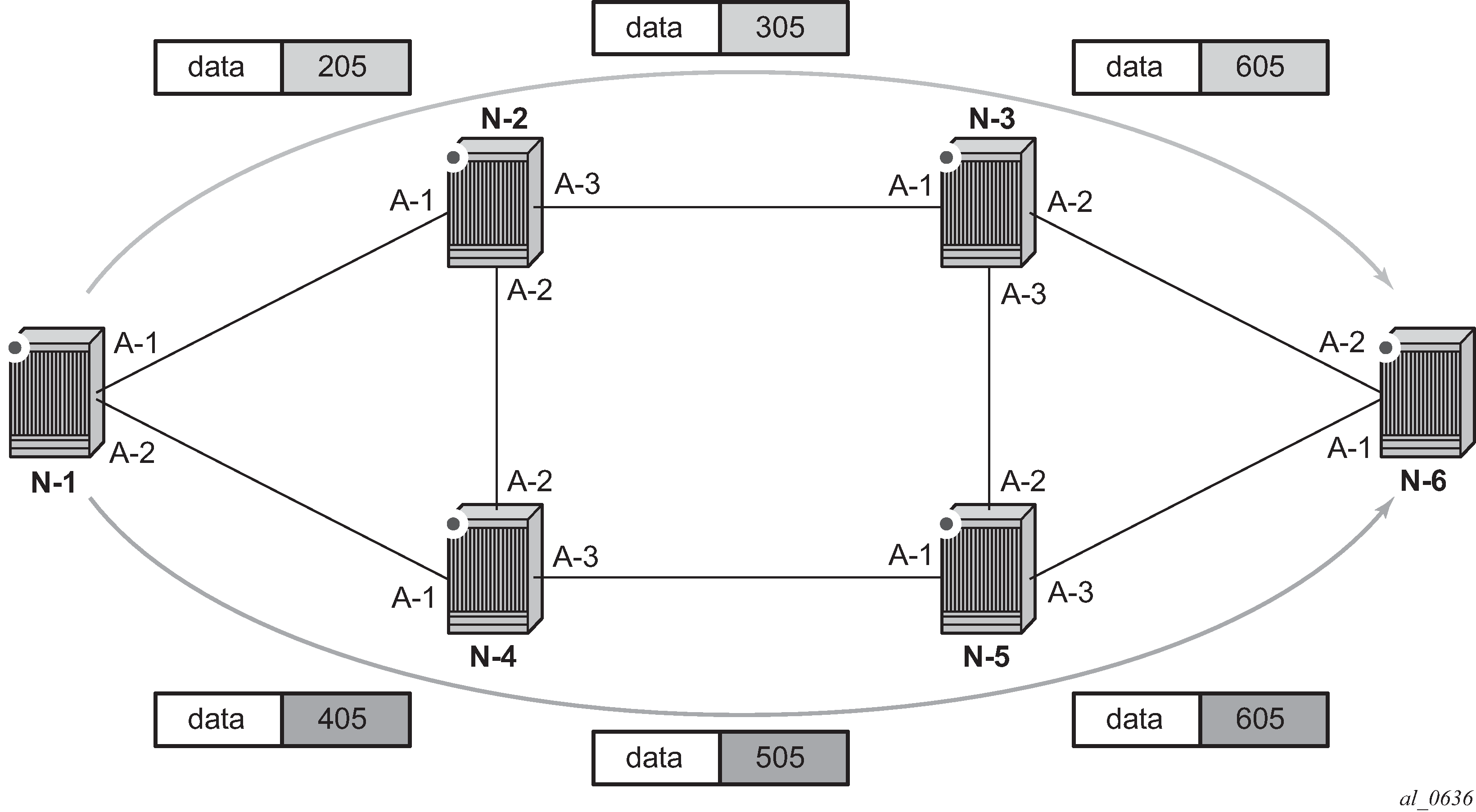
Router N-6 advertises loopback 10.10.10.1/32 with a prefix index of 5.Routers N-1 to N-6 are configured with the same SID index range of [1,100] and an offset label of 100 to 600 respectively. The following are the actual label values programmed by each router for the prefix of PE2.
N-6 has a start label value of 600 and programs an ILM with label 605.
N-3 has a start label of 300 and swaps incoming label 305 to label 605.
N-2 has a start label of 200 and swaps incoming label 205 to label 305.
Similar operations are performed by N-4 and N-5 for the alternate path.
N-1 has an SR tunnel to N-6 with two ECMP paths. It pushes label 205 when forwarding an IP or service packet to N-6 via downstream next-hop N-2 and pushes label 405 when forwarding via downstream next-hop N-4.
The CLI commands for configuring the prefix SID index range and offset label value for an IGP instance are as follows:
config>router>isis>segment-routing>prefix-sid-range {global | start-label label-value max-index index-value}
config>router>ospf>segment-routing>prefix-sid-range {global | start-label label-value max-index index-value}
There are two mutually-exclusive modes of operation for the prefix SID range on the router. In the global mode of operation, the user configures the global value and this IGP instance takes the start label value as the lowest label value in the SRGB and the prefix SID index range size equal to the range size of the SRGB. After one IGP instance selected the global option for the prefix SID range, all IGP instances on the system are restricted to do the same.
The user must shutdown the segment routing context and delete the prefix-sid-range command in all IGP instances to change the SRGB. After the SRGB is changed, the user must re-enter the prefix-sid-range command. The SRGB range change fails if an already allocated SID index or label goes out of range.
In the per-instance mode of operation, the user partitions the SRGB into non-overlapping subranges among the IGP instances. The user configures a subset of the SRGB by specifying the start label value and the prefix SID index range size. All resulting net label values (start-label + index) must be within the SRGB or the configuration fails. Furthermore, the code checks for overlaps of the resulting net label value range across IGP instances and strictly enforces that these ranges do not overlap.
The user must shutdown the segment routing context of an IGP instance to change the SID index or label range of that IGP instance using the prefix-sid-range command. In addition, any range change fails if an already allocated SID index or label goes out of range.
The user can, however, change the SRGB at any time as long as it does not reduce the current per-IGP instance SID index or label range defined with the prefix-sid-range. Otherwise, the user must shutdown the segment routing context of the IGP instance and delete and reconfigure the prefix-sid-range command.
Finally, the user brings up segment routing on that IGP instances by un-shutting the context:
config>router>isis>segment-routing>no shutdown
config>router>ospf>segment-routing>no shutdown
This command fails if the user has not previously enabled the router-capability option in the IGP instance. Segment routing is a new capability and must be advertised to all routers in a domain so that routers which support the capability only program the node SID in the data path toward neighbors which support it.
config>router>isis>advertise-router-capability {area | as}
config>router>ospf>advertise-router-capability {link | area | as}
The IGP segment routing extensions are area-scoped. As a consequence, the user must configure the flooding scope to area in OSPF and to area or as in IS-IS, otherwise performing no shutdown of the segment-routing node fail.
Next, the user assigns a node SID index or label to the prefix representing the primary address of a network interface of type system or loopback using one of the following commands. A separate SID value can be configured for each IPv4 and IPv6 primary address of the interface.
config>router>isis>interface>ipv4-node-sid index value
config>router>ospf>area>interface>node-sid index value
config>router>ospf3>area>interface>node-sid index value
config>router>isis>interface>ipv4-node-sid label value
config>router>ospf>area>interface>node-sid label value
config>router>ospf3>area>interface>node-sid label value
config>router>isis>interface>ipv6-node-sid index value
config>router>isis>interface>ipv6-node-sid label value
The secondary address of an IPv4 interface cannot be assigned a node SID index and does not inherit the SID of the primary IPv4 address. The same applies to the non-primary IPv6 addresses of an interface.
In IS-IS, an interface inherits the configured IPv4 or IPv6 node SID value in any level the interface participates in: Level 1, Level 2, or both.
In OSPFv2 and OSPFv3, the node SID is configured in the primary area but is inherited in any other area in which the interface is added as secondary.
The preceding commands fail if the network interface is not of type system or loopback, or if the interface is defined in an IES or a VPRN context. Assigning the same SID index or label value to the same interface in two different IGP instances is not allowed within the same node.
For OSPF, the protocol version number and the instance number dictates if the node SID index or label is for an IPv4 or IPv6 address of the interface. Specifically, the support of address families in OSPF is as follows:
- for ospfv2, always IPv4 only
- for ospfv3, instance 0..31, ipv6 only
- for ospfv3, instance 64..95, ipv4 only
The value of the label or index SID is taken from the range configured for this IGP instance. When using the global mode of operation, a new segment routing module checks that the same index or label value is not assigned to more than one loopback interface address. When using the per-instance mode of operation, this check is not required because the index and the label ranges of the various IGP instances cannot overlap.
For an individual adjacency, values for the label may be provisioned for an IS-IS or OSPF interface. If they are not provisioned, they are dynamically allocated by the system from the dynamic label range. The following CLI commands are used:
config>router>isis>interface
   [no] ipv4-adjacency-sid label value
   [no] ipv6-adjacency-sid label value

config>router>ospf>area>interface
   [no] adjacency-sid label value
The value must correspond to a label in a reserved label block in provisioned mode referred to by the srlb command (see Segment routing local block for more details of SRLBs).
A static label value for an adjacency SID is persistent. Therefore, the P-bit of the Flags field in the Adjacency-SID TLV advertised in the IGP is set to 1.
By default, a dynamic adjacency SID is advertised for an interface. However, if a static adjacency SID value is configured, then the dynamic adjacency SID is deleted and only the static adjacency SID used. Changing an adjacency SID from dynamic (for example, no adjacency-sid) to static, or the other way around, may result in traffic being dropped as the ILM is reprogrammed.
For a provisioned adjacency SID of an interface, a backup is calculated similar to a regular adjacency SID when sid-protection is enabled for that interface.
Provisioned adjacency SIDs are only supported on point-to-point interfaces.
Configuring single shared loopback SR SID
Segment routing shortest path forwarding with IS-IS
This section describes the segment routing shortest path forwarding with IS-IS.
IS-IS control protocol changes
New TLV and sub-TLVs are defined in draft-ietf-isis-segment-routing-extensions and are supported in the implementation of segment routing in IS-IS. Specifically:
prefix SID sub-TLV
adjacency SID sub-TLV
SID/Label Binding TLV
SR-Capabilities sub-TLV
SR-Algorithm sub-TLV
This section describes the behaviors and limitations of the IS-IS support of segment routing TLV and sub-TLVs.
SR OS supports advertising the IS router capability TLV (RFC 4971) only for topology MT=0. As a result, the segment routing capability sub-TLV can only be advertised in MT=0 which restricts the segment routing feature to MT=0.
Similarly, if prefix SID sub-TLVs for the same prefix are received in different MT numbers of the same IS-IS instance, then only the one in MT=0 is resolved. When the prefix SID index is also duplicated, an error is logged and a trap is generated, as described in Error and resource exhaustion handling.
I and V flags are both set to 1 when originating the SR capability sub-TLV to indicate support for processing both SR MPLS encapsulated IPv4 and IPv6 packets on its network interfaces. These flags are not checked when the sub-TLV is received. Only the SRGB range is processed.
The algorithm field is set to 0, meaning Shortest Path First (SPF) algorithm based on link metric, when originating the SR-Algorithm capability sub-TLV but is not checked when the sub-TLV is received.
Both IPv4 and IPv6 prefix and adjacency SID sub-TLVs originate within MT=0.
SR OS originates a single prefix SID sub-TLV per IS-IS IP-reachability TLV and processes the first prefix SID sub-TLV only if multiple are received within the same IS-IS IP-reachability TLV.
SR OS encodes the 32-bit index in the prefix SID sub-TLV. The 24-bit label is not supported.
SR OS originates a prefix SID sub-TLV with the following encoding of the flags and the following processing rules:
The R-flag is set if the prefix SID sub-TLV, along with its corresponding IP-reachability TLV, is propagated between levels. See below for more details about prefix propagation.
The N-flag is always set because SR OS supports a prefix SID type that is node SID only.
The P-Flag (no-PHP flag) is always set, meaning the label for the prefix SID is pushed by the PHP router when forwarding to this router. The SR OS PHP router processes a received prefix SID with the P-flag set to zero and uses implicit-null for the outgoing label toward the router which advertised it as long as the P-Flag is also set to 1.
The E-flag (Explicit-Null flag) is always set to zero. An SR OS PHP router, however, processes a received prefix SID with the E-flag set to 1 and, when the P-flag is also set to 1, it pushes explicit-null for the outgoing label toward the router which advertised it.
The V-flag is always set to 0 to indicate an index value for the SID.
The L-flag is always set to 0 to indicate that the SID index value is not locally significant.
The algorithm field is always set to zero to indicate Shortest Path First (SPF) algorithm based on link metric and is not checked on a received prefix SID sub-TLV.
The SR OS resolves a prefix SID sub-TLV received without the N-flag set but with the prefix length equal to 32. A trap, however, is raised by IS-IS.
The SR OS does not resolve a prefix SID sub-TLV received with the N-flag set and a prefix length different than 32. A trap is raised by IS-IS.
The SR OS resolves a prefix SID received within a IP-reachability TLV based on the following route preference:
SID received via Level 1 in a prefix SID sub-TLV part of IP-reachability TLV
SID received via Level 2 in a prefix SID sub-TLV part of IP-reachability TLV
A prefix received in an IP-reachability TLV is propagated, along with the prefix SID sub-TLV, by default from Level 1 to Level 2 by an Level 1 or Level 2 router. A router in Level 2 sets up an SR tunnel to the Level 1 router via the Level 1 or Level 2 router, which acts as an LSR.
A prefix received in an IP-reachability TLV is not propagated, along with the prefix SID sub-TLV, by default from Level 2 to Level 1 by an Level 1 or Level 2 router. If the user adds a policy to propagate the received prefix, then a router in Level 1 sets up an SR tunnel to the Level 2 router via the Level 1 or Level 2 router, which acts as an LSR.
If a prefix is summarized by an ABR, the prefix SID sub-TLV is not propagated with the summarized route between levels. To propagate the node SID for a /32 prefix, route summarization must be disabled.
SR OS propagates the prefix SID sub-TLV when exporting the prefix to another IS-IS instance; however, it does not propagate it if the prefix is exported from a different protocol. Thus, when the corresponding prefix is redistributed from another protocol such as OSPF, the prefix SID is removed.
SR OS originates an adjacency SID sub-TLV with the following encoding of the flags:
The F-flag is set to zero for IPv4 family and is set to 1 to for IPv6 family for the adjacency encapsulation.
The B-Flag is set to zero and is not processed on receipt.
The V-flag is always set to 1.
The L-flag is always set to 1.
The S-flag is set to zero because assigning adjacency SID to parallel links between neighbors is not supported. An adjacency received SID with S-Flag set is not processed.
The weight octet is not supported and is set to all zeros.
SR OS can originate the SID/Label Binding TLV as part of the Mapping Server feature (see Segment routing mapping server function for IPv4 prefixes for more information). The following rules and limitations should be considered:
Only the mapping server prefix-SID sub-TLV within the TLV is processed and the ILMs installed if the prefixes in the provided range are resolved.
The range and FEC prefix fields are processed. Each FEC prefix is resolved, similar to the prefix SID sub-TLV, meaning there must be an IP-reachability TLV received for the exact matching prefix.
If the same prefix is advertised with both a prefix SID sub-TLV and a mapping server prefix-SID sub-TLV. The resolution follows the following route preference:
SID received via Level 1 in a prefix SID sub-TLV part of IP-reachability TLV
SID received via Level 2 in a prefix SID sub-TLV part of IP-reachability TLV
SID received via Level 1 in a mapping server Prefix-SID sub-TLV
SID received via Level 2 in a mapping server Prefix-SID sub-TLV
The entire TLV can be propagated between levels based on the settings of the S-flag. The TLV cannot be propagated between IS-IS instances (see Segment routing mapping server function for IPv4 prefixes for more information). Finally, an Level 1 or Level 2 router does not propagate the prefix-SID sub-TLV from the SID/label binding TLV (received from a mapping server) into the IP-reachability TLV if the latter is propagated between levels.
The mapping server which advertised the SID/label binding TLV does not need to be in the shortest path for the FEC prefix.
If the same FEC prefix is advertised in multiple binding TLVs by different routers, the SID in the binding TLV of the first router that is reachable is used. If that router becomes unreachable, the next reachable one is used.
No check is performed if the content of the binding TLVs from different mapping servers are consistent or not.
Any other sub-TLV, for example, the SID/label sub-TLV, ERO metric and unnumbered interface ID ERO, is ignored but the user can view the octets of the received-but-not-supported sub-TLVs using the IGP show command.
Announcing ELC, MSD-ERLD, and MSD-BMI with IS-IS
IS-IS can announce node Entropy Label Capability (ELC), the Maximum Segment Depth (MSD) for node Entropy Readable Label Depth (ERLD) and the MSD for node Base MPLS Imposition (BMI). If needed, exporting the IS-IS extensions into BGP-LS requires no additional configuration. These extensions are standardized through draft-ietf-isis-mpls-elc-10, Signaling Entropy Label Capability and Entropy Readable Label Depth Using IS-IS, and RFC 8491, Signaling Maximum SID Depth (MSD) Using IS-IS.
When entropy and segment routing are enabled on a router, it automatically announces the ELC, ERLD, and BMI IS-IS values when IS-IS prefix attributes and router capabilities are announced. The following configuration logic is used.
The router automatically announces ELC for host prefixes associated with an IPv4 or IPv6 node SID when segment-routing , segment-routing entropy-label, and prefix-attributes-tlv are enabled for IS-IS. Although the ELC capability is a node property, it is assigned to prefixes to allow inter-area or inter-AS signaling. Consequently, the prefix-attribute TLV must be enabled accordingly within IS-IS.
The router announces the maximum node ERLD for IS-IS when segment-routing and segment-routing entropy-label are enabled together with advertise-router-capability.
The router announces the maximum node MSD-BMI for IS-IS when segment-routing and advertise-router-capability are enabled.
Exporting ELC, MSD-ERLD, and MSD-BMI IS-IS extensions into BGP-LS encoding is enabled automatically when database-export for BGP-LS is configured.
The announced value for maximum node MSD-ERLD and MSD-BMI can be modified to a smaller number using the override-bmi and override-erld commands. This can be useful when services (such as EVPN) or more complex link protocols (such as Q-in-Q) are deployed. Provisioning correct ERLD and BMI values helps controllers and local Constrained Shortest Path First (CSPF) to construct valid segment routing label stacks to be deployed in the network.
Segment routing parameters are configured in the following contexts:
configure>router>isis>segment-routing>maximum-sid-depth
configure>router>isis>segment-routing>maximum-sid-depth>override-bmi value
configure>router>isis>segment-routing>maximum-sid-depth>override-erld value
Entropy label for IS-IS segment routing
The router supports the MPLS entropy label, as specified in RFC 6790, on IS-IS segment-routed tunnels. LSR nodes in a network can load-balance labeled packets in a more granular way than by hashing on the standard label stack. See the MPLS Guide for more information.
Announcing of Entropy Label Capability (ELC) is supported, however processing of ELC signaling is not supported for IS-IS segment-routed tunnels. Instead, ELC is configured at the head-end LER using the configure router isis entropy-label override-tunnel-elc command. This command causes the router to ignore any advertisements for ELC that may or may not be received from the network, and instead to assume that the whole domain supports entropy labels.
IPv6 segment routing using MPLS encapsulation
This feature supports SR IPv6 tunnels in IS-IS MT=0. The user can configure a node SID for the primary IPv6 global address of a loopback interface, which is then advertised in IS-IS. IS-IS automatically assigns and advertises an adjacency SID for each adjacency with an IPv6 neighbor. After the node SID is resolved, it is used to install an IPv6 SR-ISIS tunnel in the TTM for use by the services.
IS-IS MT=0 extensions
The IS-IS MT=0 extensions support the advertising and resolution of the prefix SID sub-TLV within the IP Reachability TLV-236 (IPv6), as defined in RFC 5308.The adjacency SID is still advertised as a sub-TLV of the Extended IS Reachability TLV 22, as defined in RFC 5305, IS-IS Extensions for Traffic Engineering, as in the case of an IPv4 adjacency. The router sets the V-Flag and I-Flag in the SR-capabilities sub-TLV to indicate that it can process SR MPLS-encapsulated IPv4 and IPv6 packets on its network interfaces.
Service and forwarding contexts supported
The service and forwarding contexts supported with the SR-ISIS IPv6 tunnels are:
SDP of type sr-isis with far-end option using an IPv6 address
VLL, VPLS, IES/VPRN spoke-interface, and R-VPLS
support of PW redundancy within Epipe/Ipipe VLL, Epipe spoke termination on VPLS and R-VPLS, and Epipe/Ipipe spoke termination on IES/VPRN
IPv6 static route resolution to indirect next hop using Segment Routing IPv6 tunnel
remote mirroring and Layer 3 encapsulated lawful interface
Services using SDP with an SR IPv6 tunnel
The MPLS SDP of type sr-isis with a far-end option using an IPv6 address is supported. Note the SDP must have the same IPv6 far-end address, used by the control plane for the T-LDP session, as the prefix of the node SID of the SR IPv6 tunnel.
configure
        — service
            — [no] sdp sdp-id mpls
                — [no] far-end ipv6-address
                — sr-isis
                — no sr-isis
The bgp-tunnel, lsp, sr-te lsp, sr-ospf, and mixed-lsp-mode commands are blocked within the SDP configuration context when the far end is an IPv6 address.
SDP admin groups are not supported with an SDP using an SR IPv6 tunnel, or with SR-OSPF for IPv6 tunnels, and the attempt to assign them is blocked in the CLI.
Services that use LDP control plane such as T-LDP VPLS and R-VPLS, VLL, and IES/VPRN spoke interface have the spoke SDP (PW) signaled with an IPv6 T-LDP session because the far-end option is configured to an IPv6 address. The spoke SDP for these services binds to an SDP that uses an SR IPv6 tunnel where the prefix matches the far-end address. SR OS also supports the following:
the IPv6 PW control word with both data plane packets and VCCV OAM packets
hash label and entropy label, with the above services
network domains in VPLS
The PW switching feature is not supported with LDP IPv6 control planes. As a result, the CLI does not allow the user to enable the vc-switching option whenever one or both spoke SDPs uses an SDP that has the far-end configured as an IPv6 address.
L2 services that use BGP control plane such as dynamic MS-PW, BGP-AD VPLS, BGP-VPLS, BGP-VPWS, and EVPN MPLS cannot bind to an SR IPv6 tunnel because a BGP session to a BGP IPv6 peer does not support advertising an IPv6 next hop for the L2 NLRI. As a result, these services do not auto-generate SDPs using an SR IPv6 tunnel. In addition, they skip any provisioned SDPs with far-end configured to an IPv6 address when the use-provisioned-sdp option is enabled.
SR OS also supports multi homing with T-LDP active/standby FEC 128 spoke SDP using SR IPv6 tunnel to a VPLS/B-VPLS instance. BGP multi homing is not supported because BGP IPv6 does not support signaling an IPv6 next hop for the L2 NLRI.
The Shortest Path Bridging (SPB) feature works with spoke SDPs bound to an SDP that uses an SR IPv6 tunnel.
Segment routing mapping server function for IPv4 prefixes
The mapping server feature supports the configuration and advertisement, in IS-IS, of the node SID index for prefixes of routers in the LDP domain. This is performed in the router acting as a mapping server and using a prefix-SID sub-TLV within the SID/label binding TLV in IS-IS.
Use the following command syntax to configure the SR mapping database in IS-IS:
configure
        — router
            — [no] isis
                — segment-routing
                — no segment-routing
                    — mapping-server
                        — sid-map node-sid {index 0..4294967295 [range  0..65535]} prefix {{ip-address/mask} | {ip-address}{netmask}} [set-flags {s}] [level {1 | 2 | 1/2}]
                        — no sid-map node-sid index 0..4294967295
The user enters the node SID index, for one prefix or a range of prefixes, by specifying the first index value and, optionally, a range value. The default value for the range option is 1. Only the first prefix in a consecutive range of prefixes must be entered. If the user enters the first prefix with a mask lower than 32, the SID/label binding TLV is advertised, but a router that receives it does not resolve the prefix SID and instead generates a trap.
The no form of the sid-map command deletes the range of node SIDs beginning with the specified index value. The no form of the mapping-server command deletes all node SID entries in the IS-IS instance.
The S-flag indicates to the IS-IS routers in the network that the flooding scope of the SID/label binding TLV is the entire domain. In that case, a router receiving the TLV advertisement leaks it between IS-IS levels. If leaked from Level 2 to Level 1, the D-flag must be set; this prevents the TLV from being leaked back into level 2. Otherwise, the S-flag is clear by default and routers receiving the mapping server advertisement do not leak the TLV.
SR OS does not leak this TLV between IS-IS instances and does not support the multi-topology SID/label binding TLV format. In addition, the user can specify the flooding scope of the mapping server for the generated SID/label binding TLV using the level option. This option allows further narrowing of the flooding scope configured under the router IS-IS level-capability for one or more SID/label binding TLVs if required. The default flooding scope of the mapping server is L1 or L2, which can be narrowed by what is configured under the router IS-IS level-capability.
The A-flag indicates that a prefix for which the mapping server prefix SID is advertised is directly attached. The M-flag advertises a SID for a mirroring context to provide protection against the failure of a service node. None of these flags are supported on the mapping server; the mapping client ignores them.
Each time a prefix or a range of prefixes is configured in the SR mapping database in any routing instance, the router issues for this prefix, or range of prefixes, a prefix-SID sub-TLV within an IS-IS SID/label binding TLV in that instance. The flooding scope of the TLV from the mapping server is determined as previously described. No further check of the reachability of that prefix in the mapping server route table is performed. No check of the SID index is performed to determine whether the SID index is a duplicate of an existing prefix in the local IGP instance database or if the SID index is out of range with the local SRGB.
IP prefix resolution for segment routing mapping server
The following processing rules apply for IP prefix resolution.
-
SPF calculates the next hops, up to max-ecmp, to reach a destination node.
-
Each prefix inherits the next hops of one or more destination nodes advertising it.
-
A prefix advertised by multiple nodes, all reachable with the same cost, inherits up to max-ecmp next hops from the advertising nodes.
-
The next-hop selection value, up to max-ecmp, is based on sorting the next hops by:
-
lowest next-hop router ID
-
lowest interface index, for parallel links to same router ID
Each next hop keeps a reference to the destination nodes from which it was inherited.
-
Prefix SID resolution for segment routing mapping server
The following processing rules apply for prefix SID resolution.
-
For a specific prefix, IGP selects the SID value among multiple advertised values in the following order:
-
local intra-area SID owned by this router
-
prefix SID sub-TLV advertised within an IP Reachability TLV
If multiple SIDs exist, select the SID corresponding to the destination router or the ABR with the lowest system ID that is reachable using the first next hop of the prefix.
-
IS-IS SID and label binding TLV from the mapping server
If multiple SIDs exist, select the following, using the preference rules in draft-ietf-spring-conflict-resolution-05 [sid-conflict-resolution] when applied to the SRMS entries of the conflicting SIDs. The order of these rules is as follows:
- smallest range
- smallest starting address
- smallest algorithm
- smallest starting SID
Note: If an L1L2 router acts as a mapping server and also re-advertises the mapping server prefix SID from other mapping servers, the redistributed mapping server prefix SID is preferred by other routers resolving the prefix, which may result in not selecting the mapping server respecting these rules. -
-
The selected SID is used with all ECMP next-hops from step 1 toward all destination nodes or ABR nodes which advertised the prefix.
-
If duplicate prefix SIDs exist for different prefixes after the above steps, the first SID that is processed is programmed for its corresponding prefix. Subsequent SIDs cause a duplicate SID trap message and are not programmed. The corresponding prefixes are still resolved and programmed normally using IP next-next-hops.
SR tunnel programming for segment routing mapping server
The following processing rules apply for SR tunnel programming.
-
If the prefix SID is resolved from a prefix SID sub-TLV advertised within an IP Reachability TLV, one of the following applies:
-
The SR ILM label is swapped to an SR NHLFE label, as in SR tunnel resolution when the next hop of the IS-IS prefix is SR-enabled.
-
The SR ILM label is stitched to an LDP FEC of the same prefix when either the next hop of the IS-IS prefix is not SR-enabled (no SR NHLFE) or an import policy rejects the prefix (SR NHLFE is deprogrammed).
The LDP FEC can also be resolved by using the same or a different IGP instance as that of the prefix SID sub-TLV or by using a static route.
-
-
If the prefix SID is resolved from a mapping server advertisement, one of the following applies:
-
The SR ILM label is stitched to an LDP FEC of the same prefix, if one exists. The stitching is performed even if an import policy rejects the prefix in the local ISIS instance.
The LDP FEC can also be resolved by using a static route, a route within an IS-IS instance, or a route within an OSPF instance. The IS-IS or OSPF instances can be the same as, or different form the IGP instance that advertised the mapping server prefix SID sub-TLV.
-
The SR ILM label is swapped to an SR NHLFE label. This is only possible if a route is exported from another IGP instance into the local IGP instance without propagating the prefix SID sub-TLV with the route. Otherwise, the SR ILM label is swapped to an SR NHLFE label toward the stitching node.
-
Segment routing shortest path forwarding with OSPF
This section describes the segment routing shortest path forwarding with OSPF.
OSPFv2 control protocol changes
New TLVs and sub-TLVs are defined in draft-ietf-ospf-segment-routing-extensions-04 and are required for the implementation of segment routing in OSPF. Specifically:
prefix SID sub-TLV part of the OSPFv2 Extended Prefix TLV
prefix SID sub-TLV part of the OSPFv2 Extended Prefix Range TLV
adjacency SID sub-TLV part of the OSPFv2 Extended Link TLV
SID/Label Range capability TLV
SR-Algorithm capability TLV
This section describes the behaviors and limitations of OSPF support of segment routing TLV and sub-TLVs.
SR OS originates a single prefix SID sub-TLV per OSPFv2 Extended Prefix TLV and processes the first one only if multiple prefix SID sub-TLVs are received within the same OSPFv2 Extended Prefix TLV.
SR OS encodes the 32-bit index in the prefix SID sub-TLV. The 24-bit label or variable IPv6 SID is not supported.
SR OS originates a prefix SID sub-TLV with the following encoding of the flags:
The NP-Flag is always set. The label for the prefix SID is pushed by the PHP router when forwarding to this router. SR OS PHP routers process a received prefix SID with the NP-flag set to zero and use implicit-null for the outgoing label toward the router which advertised it.
The M-Flag is always unset because SR OS does not support originating a mapping server prefix-SID sub-TLV.
The E-flag is always set to zero. SR OS PHP routers process a received prefix SID with the E-flag set to 1, and when the NP-flag is also set to 1 they push explicit-null for the outgoing label toward the router which advertised it.
The V-flag is always set to 0 to indicate an index value for the SID.
The L-flag is always set to 0 to indicate that the SID index value is not locally significant.
The algorithm field is set to zero to indicate Shortest Path First (SPF) algorithm based on link IGP metric or to the flexible algorithm number.
SR OS resolves a prefix SID received within an Extended Prefix TLV based on the following route preference:
SID received via an intra-area route in a prefix SID sub-TLV part of Extended Prefix TLV
SID received via an inter-area route in a prefix SID sub-TLV part of Extended Prefix TLV
SR OS originates an adjacency SID sub-TLV with the following encoding of the flags:
The B-flag is set to zero and is not processed on receipt.
The V-flag is always set.
The L-flag is always set.
The G-flag is not supported.
The weight octet is not supported and is set to all zeros.
An adjacency SID is assigned to next hops over both the primary and secondary interfaces.
SR OS can originate the OSPFv2 Extended Prefix Range TLV as part of the Mapping Server feature and can process it properly, if received. Consider the following rules and limitations:
Only the prefix SID sub-TLV within the TLV is processed and the ILMs installed if the prefixes are resolved.
The range and address prefix fields are processed. Each prefix is resolved separately.
If the same prefix is advertised with both a prefix SID sub-TLV in an IP-reachability TLV and a mapping server Prefix-SID sub-TLV, the resolution follows the following route preference:
the SID received via an intra-area route in a prefix SID sub-TLV part of Extended Prefix TLV
the SID received via an inter-area route in a prefix SID sub-TLV part of Extended Prefix TLV
the SID received via an intra-area route in a prefix SID sub-TLV part of a OSPFv2 Extended Range Prefix TLV
the SID received via an inter-area route in a prefix SID sub-TLV part of a OSPFv2 Extended Range Prefix TLV
Leaking does not occur within the TLV between areas. Also, an ABR does not propagate the prefix-SID sub-TLV from the Extended Prefix Range TLV (received from a mapping server) into an Extended Prefix TLV if the latter is propagated between areas.
The mapping server which advertised the OSPFv2 Extended Prefix Range TLV does not need to be in the shortest path for the FEC prefix.
If the same FEC prefix is advertised in multiple OSPFv2 Extended Prefix Range TLVs by different routers, the SID in the TLV of the first router that is reachable is used. If that router becomes unreachable, the next reachable one is used.
There is no check to determine whether the contents of the OSPFv2 Extended Prefix Range TLVs received from different mapping servers are consistent.
Any other sub-TLV, for example, the ERO metric and unnumbered interface ID ERO, is ignored but the user can get a dump of the octets of the received-but-not-supported sub-TLVs using the existing IGP show command.
SR OS supports propagation on the ABR of external prefix LSAs into other areas with routeType set to 3 as per draft-ietf-ospf-segment-routing-extensions-04.
SR OS supports propagation on the ABR of external prefix LSAs with route type 7 from NSSA area into other areas with route type set to 5 as per draft-ietf-ospf-segment-routing-extensions-04. SR OS does not support propagating the prefix SID sub-TLV between OSPF instances.
When the user configures an OSPF import policy, the outcome of the policy applies to prefixes resolved in RTM and the corresponding tunnels in TTM. So, a prefix removed by the policy does not appear as both a route in RTM and as an SR tunnel in TTM.
OSPFv3 control protocol changes
The OSPFv3 extensions support the following TLVs:
a prefix SID that is a sub-TLV of the OSPFv3 prefix TLV
The OSPFv3 prefix TLV is a new top-level TLV of the extended prefix LSA introduced in draft-ietf-ospf-ospfv3-lsa-extend. The OSPFv3 instance can operate in either LSA sparse mode or extended LSA mode.
The config>router>extended-lsa only command advertises the prefix SID sub-TLV in the extended LSA format in both cases.
an adjacency SID that is a sub-TLV of the OSPFv3 router-link TLV
The OSPFv3 router-link TLV is a new top-level TLV in the extended router LSA introduced in draft-ietf-ospf-ospfv3-lsa-extend. The OSPFv3 instance can operate in either LSA sparse mode or extended LSA mode. The config>router>extended-lsa only command advertises the adjacency SID sub-TLV in the extended LSA format in both cases.
the SR-Algorithm TLV and the SID/Label range TLV
Both of these TLVs are part of the TLV-based OSPFv3 Router Information Opaque LSA defined in RFC 7770.
Announcing ELC, MSD-ERLD and MSD-BMI with OSPF
OSPF has the ability to announce node Entropy Label Capability (ELC), the Maximum Segment Depth (MSD) for node Entropy Readable Label Depth (ERLD), and the Maximum Segment Depth (MSD) for node Base MPLS Imposition (BMI). If needed, exporting these OSPF extensions into BGP-LS requires no additional configuration. These extensions are standardized through draft-ietf-ospf-mpls-elc-12, Signaling Entropy Label Capability and Entropy Readable Label-stack Depth Using OSPF, and RFC 8476, Signaling Maximum SID Depth (MSD) Using OSPF.
The ELC, ERLD, and BMI OSPF values are announced automatically when entropy and segment routing is enabled on the router. The following configuration logic is used:
ELC is automatically announced for host prefixes associated with a node SID when segment-routing and segment-routing entropy-label are enabled for OSPF.
The router maximum node ERLD is announced for OSPF when segment-routing and segment-routing entropy-label is enabled together with advertise-router-capability.
The router maximum node MSD-BMI for OSPF is announced when segment-routing advertise-router-capability are enabled.
Exporting ELC, MSD-ERLD and MSD-BMI OSPF extensions into BGP-LS encoding occurs automatically when database-export for BGP-LS is configured.
The announced value for maximum node MSD-ERLD and MSD-BMI can be modified to a smaller number using the override-bmi and override-erld commands. This can be useful when services (such as EVPN) or more complex link protocols (such as Q-in-Q) are deployed. Provisioning correct ERLD and BMI values helps controllers and local-cspf to construct valid segment routing label stacks to be deployed in the network.
Segment routing parameters are configured in the following context:
configure>router>ospf>segment-routing
configure>router>ospf>segment-routing>override-bmi value
configure>router>ospf>segment-routing>override-erld value
Entropy label for OSPF segment routing
The router supports the MPLS entropy label, as specified in RFC 6790, on OSPF segment-routed tunnels. LSR nodes in a network can load-balance labeled packets in a more granular way than by hashing on the standard label stack. See the MPLS Guide for more information.
Announcing of Entropy Label Capability (ELC) is supported, however, processing of ELC signaling is not supported for OSPF segment-routed tunnels. Instead, ELC is configured at the head-end LER using the configure router ospf entropy-label override-tunnel-elc command. This command causes the router to ignore any advertisements for ELC that may or may not be received from the network, and to assume that the whole domain supports entropy labels.
IPv6 segment routing using MPLS encapsulation in OSPFv3
This feature supports SR IPv6 tunnels in OSPFv3 instances 0 to 31. The user can configure a node SID for the primary IPv6 global address of a loopback interface, which then gets advertised in OSPFv3. OSPFv3 automatically assigns and advertises an adjacency SID for each adjacency with an IPv6 neighbor. After the node SID is resolved, it is used to install an IPv6 SR-OSPF3 tunnel in the TTMv6 for use by the routes and services.
Segment routing mapping server for IPv4 prefixes
The mapping server feature configures and advertises, in OSPF, of the node SID index for prefixes of routers which are in the LDP domain. This is performed in the router acting as a mapping server and using a prefix-SID sub-TLV within an OSPF Extended Prefix Range TLV.
Use the following command syntax to configure the SR mapping database in OSPF:
configure
        — router
            — [no]ospf
                — segment-routing
                — no segment-routing
                    — mapping-server
                        — sid-map node-sid {index value 0 to 4294967295 [range value 1 to 65535]} prefix {{ip-address/mask}|{netmask}}[scope {area area-id | as}]
                        — no sid-map node-sid index value
The user enters the node SID index, for one prefix or a range of prefixes, by specifying the first index value and, optionally, a range value. The default value for the range option is 1. Only the first prefix in a consecutive range of prefixes must be entered. If the user enters the first prefix with a mask lower than 32, the OSPF Extended Prefix Range TLV is advertised but a router that receives the OSPF Extended Prefix Range TLV does not resolve the SID and instead generates a trap.
The no form of the sid-map command deletes the range of node SIDs beginning with the specified index value. The no form of the mapping-server command deletes all node SID entries in the OSPF instance.
Use the scope option to specify the flooding scope of the mapping server for the generated OSPF Extended Prefix Range TLV. There is no default value. If the scope is a specific area, the TLV is flooded only in that area.
An ABR that propagates an intra-area OSPF Extended Prefix Range TLV flooded by the mapping server in that area into other areas sets the inter-area flag (IA-flag). The ABR also propagates the TLV if it is received with the inter-area flag set from other ABR nodes but only from the backbone to leaf areas and not leaf areas to the backbone. However, if the identical TLV was advertised as an intra-area TLV in a leaf area, the ABR does not flood the inter-area TLV into that leaf area.
Each time a prefix or a range of prefixes is configured in the SR mapping database in any routing instance, the router issues for this prefix, or range of prefixes, a prefix-SID sub-TLV within an OSPF Extended Prefix Range TLV in that instance. The flooding scope of the TLV from the mapping server is determined as previously described. The reachability of that prefix in the mapping server route table is not checked. Additionally, the SR OS does not check whether the SID index is a duplicate of an existing prefix in the local IGP instance database or if the SID index is out of range with the local SRGB.
IP prefix resolution for segment routing mapping server
The following processing rules apply for IP prefix resolution.
-
SPF calculates the next hops, up to max-ecmp, to reach a destination node.
-
Each prefix inherits the next hops of one or more destination nodes advertising it.
-
A prefix advertised by multiple nodes, all reachable with the same cost, inherits up to max-ecmp next hops from the advertising nodes.
-
The next-hop selection value, up to max-ecmp, is based on sorting the next hops by:
-
lowest next-hop router ID
-
lowest interface index, for parallel links to same router ID
Each next hop keeps a reference to the destination nodes from which it was inherited.
-
Prefix SID resolution for segment routing mapping server
The following processing rules apply for prefix SID resolution.
-
For a specific prefix, IGP selects the SID value among multiple advertised values in the following order:
-
local intra-area SID owned by this router
-
prefix SID sub-TLV advertised within a OSPF Extended Prefix TLV
If multiple SIDs exist, select the SID corresponding to the destination router or ABR with the lowest OSPF Router ID which is reachable via the first next hop of the prefix
-
OSPF Extended Prefix Range TLV from mapping server
If multiple SIDs exist, select the following, using the preference rules in draft-ietf-spring-conflict-resolution-05 when applied to the SRMS entries of the conflicting SIDs. The order of these rules is as follows:
- smallest range
- smallest starting address
- smallest algorithm
- smallest starting SID
-
-
The selected SID is used with all ECMP next hops from step 1 toward all destination nodes or ABR nodes which advertised the prefix.
-
If duplicate prefix SIDs exist for different prefixes after above steps, the first SID which is processed is programmed for its corresponding prefix. Subsequent SIDs causes a duplicate SID trap message and are not programmed. The corresponding prefixes are still resolved normally using IP next hops.
SR tunnel programming for segment routing mapping server
The following processing rules apply for SR tunnel programming.
-
If the prefix SID is resolved from a prefix SID sub-TLV advertised within an OSPF Extended Prefix TLV, one of the following applies:
-
The SR ILM label is swapped to an SR NHLFE label as in SR tunnel resolution when the next hop of the OSPF prefix is SR-enabled.
-
The SR ILM label is stitched to an LDP FEC of the same prefix when either the next hop of the OSPF prefix is not SR enabled (no SR NHLFE) or an import policy rejects the prefix (SR NHLFE deprogrammed).
The LDP FEC can also be resolved using the same or a different IGP instance as that of the prefix SID sub-TLV or using a static route.
-
-
If the prefix SID is resolved from a mapping server advertisement, one of the following applies:
-
The SR ILM label is stitched to an LDP FEC of the same prefix, if one exists. The stitching is performed even if an import policy rejects the prefix in the local OSPF instance.
The LDP FEC can also be resolved using a static route, a route within an IS-IS instance, or a route within an OSPF instance. The latter two can be the same as, or different from the IGP instance that advertised the mapping server prefix SID sub-TLV.
-
The SR ILM label is swapped to an SR NHLFE label toward the stitching node.
-
Segment routing with BGP
Segment routing allows a router, potentially by action of an SDN controller, to source route a packet by prepending a segment router header containing an ordered list of SIDs. Each SID can be viewed as some sort of topological or service-based instruction. A SID can have a local impact to one particular node or it can have a global impact within the SR domain, such as the instruction to forward the packet on the ECMP-aware shortest path to reach a prefix P. With SR-MPLS, each SID is an MPLS label and the complete SID list is a stack of labels in the MPLS header.
For all the routers in a network domain to have a common interpretation of a topology SID, the association of the SID with an IP prefix must be propagated by a routing protocol. Traditionally this is done by an IGP protocol, however, in some cases the effect of a SID may need to be carried across network boundaries that extend beyond IGP protocol boundaries. For these cases, BGP can carry the association of an SR-MPLS SID with an IP prefix. This is possible by attaching a prefix-SID BGP path attribute to an IP route belonging to a labeled-unicast address family. The prefix SID attribute attached to a labeled-unicast route for prefix P advertises a SID corresponding to the network-wide instruction to forward the packet along the ECMP-aware BGP-computed best path or paths to reach P. The prefix-SID attribute is an optional, transitive BGP path attribute with type code 40. This attribute encodes a 32-bit label-index (into the SRGB space) and also provides details about the SRGB space of the originating router. The encoding of this BGP path attribute and its semantics are further described in draft-ietf-idr-bgp-prefix-sid.
An SR OS router with upgraded software that processes the prefix SID attribute can prevent it from propagating outside the segment routing domain where it is applicable, using the block-prefix-sid command. This BGP command removes the prefix SID attribute from all routes sent and received to and from the IBGP and EBGP peers included in the scope of the command. By default, the attribute propagates without restriction.
SR OS attaches a meaning to a prefix SID attribute only when it is attached to routes belonging to the labeled-unicast IPv4 and labeled-unicast IPv6 address families. When attached to routes of unsupported address families, the prefix SID attribute is ignored but still propagated, as with any other optional transitive attribute.
Segment routing must be administratively enabled under BGP using the following command: config>router>bgp>segment-routing>no shutdown for any of the following behaviors to be possible:
For BGP to redistribute a static or IGP route for a /32 IPv4 prefix as a label-ipv4 route, or a /128 IPv6 prefix as a label-ipv6 route, with a prefix SID attribute, a route-table-import policy with an sr-label-index action is required.
For BGP to add or modify the prefix SID attribute in a received label-ipv4 or label-ipv6 route, a BGP import policy with an sr-label-index action is required.
For BGP to advertise a label-ipv4 or label-ipv6 route with an incoming datapath label based on the attached prefix SID attribute when BGP segment-routing is disabled, new label values assigned to label-ipv4 or label-ipv6 routes come from the dynamic label range of the router and has no network-wide impact.
To enable BGP segment routing, the base router BGP instance must be associated with a prefix-sid-range. This command specifies which SRGB label block to use (for example, to allocate labels). This command also specifies which SRGB label block to advertise in the Originator SRGB TLV of the prefix SID attribute. The global parameter value indicates that BGP should use the SRGB as configured under config>router>mpls-labels>sr-labels. The start-label and max-index parameters are used to restrict the BGP prefix SID label range to a subset of the global SRGB.
This is useful when partitioning of the SRGB into non-overlapping subranges dedicated to different IGP/BGP protocol instances is required. Segment routing under BGP must be shutdown before any changes can be made to the prefix-sid-range command.
A unique label-index value is assigned to each unique IPv4 or IPv6 prefix that is advertised with a BGP prefix SID. If label-index N1 is assigned to a BGP-advertised prefix P1, and N1 plus the SRGB start-label creates a label value that conflicts with another SR programmed LFIB entry, then the conflict situation is addressed according to the following rules:
-
If the conflict is with another BGP route for prefix P2 that was advertised with a prefix SID attribute, all the conflicting BGP routes (for P1 and P2) are advertised with a normal BGP-LU label from the dynamic label range.
-
If the conflict is with an IGP route, and BGP is not attempting to redistribute that IGP route as a label-ipv4 or label-ipv6 route with a route-table-import policy action that uses the prefer-igp keyword in the sr-label-index command, the IGP route takes priority and the BGP route is advertised with a normal BGP-LU label from the dynamic label range.
-
If the conflict is with an IGP route, and BGP is trying to redistribute that IGP route as a label-ipv4 or label-ipv6 route with a route-table-import policy action that uses the prefer-igp keyword in the sr-label-index command, this is not considered a conflict and BGP uses the IGP-signaled label-index to derive its advertised label. This has the effect of stitching the BGP segment routing tunnel to the IGP segment routing tunnel.
Any /32 label-ipv4 or /128 label-ipv6 BGP routes containing a prefix SID attribute can be resolved and used in the same way as /32 label-ipv4 or /128 label-ipv6 routes without a prefix SID attribute. That is, these routes are installed in the route table and tunnel table (unless disable-route-table-install or selective-label-ipv4-install are in effect), and they can have ECMP next hops or FRR backup next hops and be used as transport tunnels for any service that supports BGP-LU transport.
Note that receiving a /32 label-ipv4 or /128 label-ipv6 route with a prefix-SID attribute does not create a tunnel in the segment-routing database; it only creates a label swap entry when the route is re-advertised with a new next hop. It is recommended the first SID in any SID-list of an SR policy should not be based on a BGP prefix SID; if this recommendation is not followed, then the SID-list may appear to be valid but the datapath is not programmed correctly. However, it is acceptable to use a BGP prefix SID for any SID other than first SID in any SR policy.
Segment routing operational procedures
Prefix advertisement and resolution
After segment routing is successfully enabled in the IS-IS or OSPF instance, the router performs the following operations. See IS-IS control protocol changes, OSPFv2 control protocol changes, and OSPFv3 control protocol changes for information about all TLVs and sub-TLVs for both IS-IS and OSPF protocols.
-
Advertise the Segment Routing Capability sub-TLV to routers in all areas or levels of this IGP instance. However, only neighbors with which it established an adjacency interpret the SID/label range information and use it for calculating the label to swap to or push for a specific resolved prefix SID.
-
Advertise the assigned index for each configured node SID in the new prefix SID sub-TLV with the N-flag (node-SID flag) set. The segment routing module programs the ILM with a pop operation for each local node SID in the data path.
-
Assign and advertise an adjacency SID label for each formed adjacency over a network IP interface in the new Adjacency SID sub-TLV. The following points should be considered:
-
Adjacency SID is advertised for both numbered and unnumbered network IP interfaces.
-
Adjacency SID is not advertised for an IES interface because access interfaces do not support MPLS.
-
Adjacency SID must be unique per instance and per adjacency. ISIS MT=0 can establish an adjacency for both IPv4 and IPv6 address families over the same link. In this case, a different adjacency SID is assigned to each next hop. However, the existing IS-IS implementation assigns a single Protect-Group ID (PG-ID) to the adjacency and therefore when the state machine of a BFD session tracking the IPv4 or IPv6 next hop times out, an action is triggered for the prefixes of both address families over that adjacency.
The segment routing module programs the ILM with a swap to an implicit null label operation for each advertised adjacency SID.
-
-
Resolve received prefixes and, if a prefix SID sub-TLV exists, the Segment Routing module programs the ILM with a swap operation and an LTN with a push operation, both pointing to the primary/LFA NHLFE. An SR tunnel is also added to the TTM. If a node SID resolves over an IES interface, the data path is not programmed and a trap message is generated. Thus, only next-hops of an ECMP set corresponding to network IP interfaces are programmed in the data path; next-hops corresponding to IES interfaces are not programmed. However, if the user configures the interface as network on one side and IES on the other side, MPLS packets for the SR tunnel received on the access side are dropped.
-
LSA filtering causes SIDs not to be sent in one direction which means some node SIDs is resolved in parts of the network upstream of the advertisement suppression.
When the user enables segment routing in an IGP instance, the main SPF and LFA SPF are computed normally and the primary next hop and LFA backup next hop for a received prefix are added to RTM without the label information advertised in the prefix SID sub-TLV. In all cases, the segment routing (SR) tunnel is not added into RTM.
Error and resource exhaustion handling
Supporting multiple topologies for the same destination prefix
The SR OS supports assigning different prefix-SID indexes and labels to the same prefix in different IGP instances. While other routers that receive these prefix SIDs program a single route into RTM, based on the winning instance ID as per RTM route type preference, the SR OS adds two tunnels to this destination prefix in TTM. This supports multiple topologies for the same destination prefix.
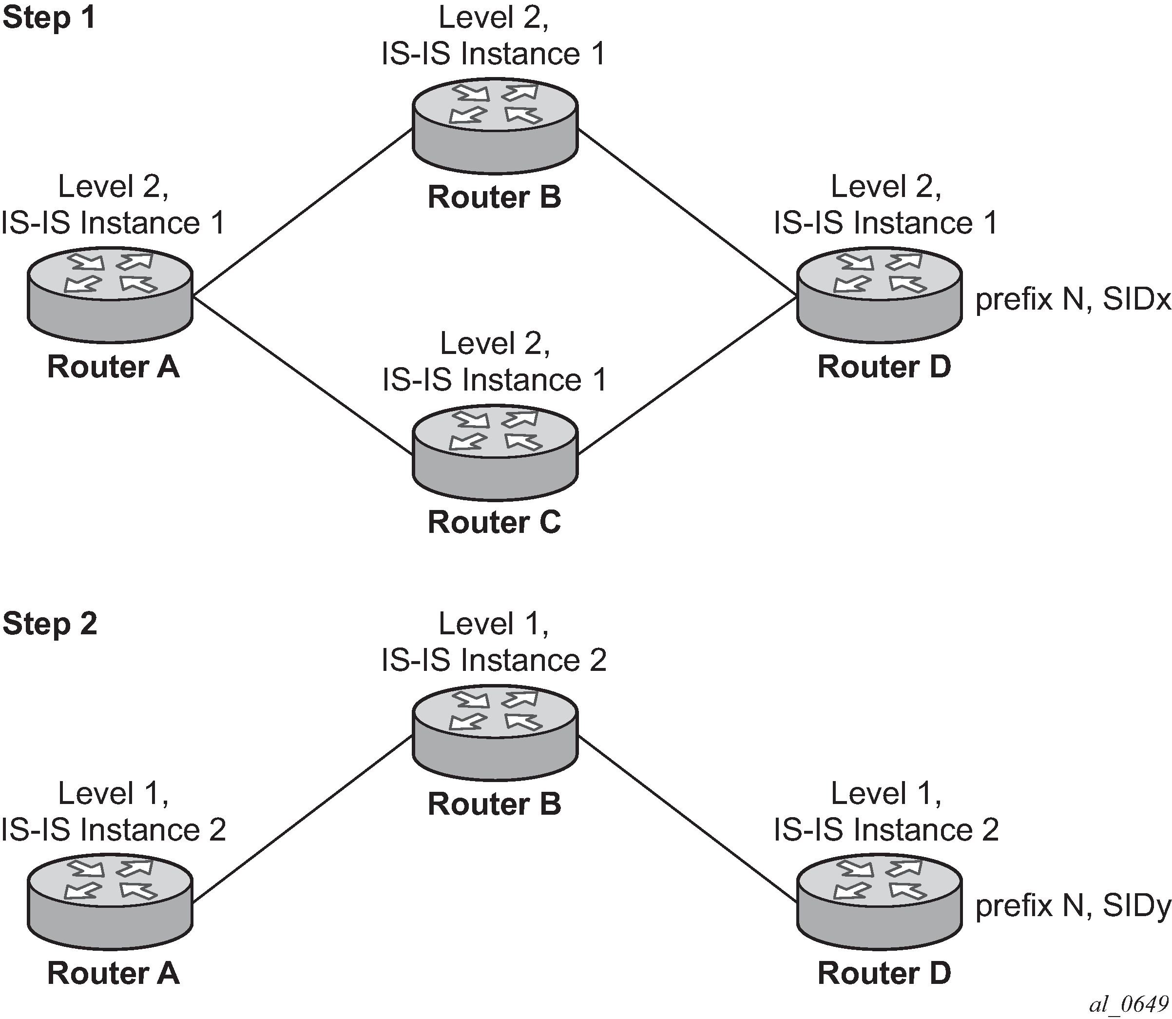
For example: in two instances (L2, IS-IS instance 1 and L1, IS-IS instance 2—see Programming multiple tunnels to the same destination), Router D has the same prefix destination (N) with different SIDs (SIDx and SIDy).
Assume the following route-type preference in RTM and tunnel-type preference in TTM are configured:
-
ROUTE_PREF_ISIS_L1_INTER (RTM) 15
-
ROUTE_PREF_ISIS_L2_INTER (RTM) 18
-
ROUTE_PREF_ISIS_TTM 10
- Router A performs the following resolution within the single IS-IS instance 1,
level 2. All metrics are the same, and ECMP = 2.
-
For prefix N, the RTM entry is:
-
prefix N
-
nhop1 = B
-
nhop2 = C
-
preference 18
-
-
For prefix N, the SR tunnel TTM entry is:
-
tunnel-id 1: prefix N-SIDx
-
nhop1 = B
-
nhop2 = C
-
tunl-pref 10
-
-
- Add IS-IS instance 2 (Level 1) in the same configuration, but in routers A, B, and
C only.
-
For prefix N, the RTM entry is:
-
prefix N
-
nhop1 = B
-
preference 15
RTM prefers L1 route over L2 route
-
-
For prefix N, there are two SR tunnel entries in TTM:
SR entry for L2:
-
tunnel-id 1: prefix N-SIDx
-
nhop1 = B
-
nhop2= C
-
tunl-pref 10
SR entry for L1 is tunnel-id 2: prefix N-SIDy.
-
-
Resolving received SID indexes or labels to different routes of the same prefix within the same IGP instance
The router can perform the following variations of this procedure:
-
When the SR OS does not allow assigning the same SID index or label to different routes of the same prefix within the same IGP instance, the router resolves only one of the duplicate SIDs if the SIDs are received from another segment routing implementation and the SIDs are based on the RTM active route selection.
-
When SR OS does not allow assigning different SID indexes or labels to different routes of the same prefix within the same IGP instance, the router resolves only one of the duplicate SIDs if the SIDs are received from another segment routing implementation and the SIDs are based on the RTM active route selection.
The selected SID is used for ECMP resolution to all neighbors. If the route is inter-area and the conflicting SIDs are advertised by different ABRs, ECMP toward all ABRs uses the selected SID.
Checking for SID errors before programming the ILM and NHLFE
If any of the following conditions are true, the router logs a trap, generates a syslog error message, and does not program the ILM and NHLFE for the prefix SID.
-
The received prefix SID index falls outside of the locally configured SID range.
-
One or more resolved ECMP next-hops for a received prefix SID did not advertise the SR Capability sub-TLV.
-
The received prefix SID index falls outside the advertised SID range of one or more resolved ECMP next-hops.
Programming ILM/NHLFE for duplicate prefix-SID indexes/labels for different prefixes
The router can perform the following variations of this procedure:
-
For received duplicate prefix-SID indexes or labels for different prefixes within the same IGP instance, the router:
-
programs the ILM/NHLFE for the first prefix-SID index or label
-
logs a trap and generates a syslog error message
-
does not program the subsequent prefix-SID index or label in the datapath
-
-
For received duplicate prefix-SID indexes or labels for different prefixes across IGP instances, there are two options.
-
In the global SID index range mode of operation, the resulting ILM label value is the same across the IGP instances. The router:
-
programs ILM/NHLFE for the prefix of the winning IGP instance based on the RTM route-type preference
-
logs a trap and generates a syslog error message
-
does not program the subsequent prefix SIDs in the datapath
-
-
In the per-instance SID index range mode of operation, the resulting ILM label has different values across the IGP instances. The router programs ILM/NHLFE for each prefix as expected.
-
Programming ILM/NHLFE for the same prefix across IGP instances
In global SID index range mode of operation, the resulting ILM label value is the same across the IGP instances. The router programs ILM/NHLFE for the prefix of the winning IGP instance based on the RTM route-type preference. The router logs a trap and generates a syslog error message, and does not program the other prefix SIDs in the datapath.
In the per-instance SID index range mode of operation, the resulting ILM label has different values across the IGP instances. The router programs ILM/NHLFE for each prefix as expected.
The following figure shows an IS-IS example of handling in case of a global SID index range.

Assume the following route-type preference in RTM and tunnel-type preference in TTM are configured:
-
ROUTE_PREF_ISIS_L1_INTER (RTM) 15
-
ROUTE_PREF_ISIS_L2_INTER (RTM) 18
-
ROUTE_PREF_ISIS_TTM 10
- Router A performs the following resolution within the single level 2, IS-IS instance 1. All
metrics are the same and ECMP = 2.
-
For prefix N, the RTM entry is:
-
prefix N
-
nhop1 = B
-
nhop2 = C
-
preference 18
-
-
For prefix N, the SR tunnel TTM entry is:
-
tunnel-id 1: prefix N-SIDx
-
nhop1 = B
-
nhop2 = C
-
tunl-pref 10
-
-
- Add Level 1, IS-IS instance 2 in the same configuration, but in routers A, B, and E only.
-
For prefix N, the RTM entry is:
-
prefix N
-
nhop1 = B
-
preference 15
The RTM prefers L1 route over L2 route.
-
-
For prefix N, there is one SR tunnel entry for L2 in TTM:
-
tunnel-id 1: prefix N-SIDx
-
nhop1 = B
-
nhop2 = C
-
tunl-pref 10
-
-
Handling ILM resource exhaustion while assigning a SID index/label
If the system exhausted an ILM resource while assigning a SID index/label to a local loopback interface, then index allocation fails and an error is displayed in the CLI. The router logs a trap and generates a syslog error message.
Handling ILM, NHLFE, or other IOM or CPM resource exhaustion while resolving or programming a SID index/label
If the system exhausted an ILM, NHLFE, or any other IOM or CPM resource while resolving and programming a received prefix SID or programming a local adjacency SID, the following occurs:
-
The IGP instance goes into overload and a trap and syslog error message are generated.
-
The segment routing module deletes the tunnel.
The user must manually clear the IGP overload condition after freeing resources. After the IGP is brought back up, it attempts to program all tunnels that previously failed the programming operation at the next SPF.
Segment routing tunnel management
The segment routing module adds a shortest path SR tunnel entry to TTM for each resolved remote node SID prefix and programs the data path with the corresponding LTN with the push operation pointing to the primary and LFA backup NHLFEs. The LFA backup next hop for a prefix which was advertised with a node SID is only computed if the loopfree-alternates option is enabled in the IS-IS or OSPF instance. The resulting SR tunnel that is populated in TTM is automatically protected with FRR when an LFA backup next hop exists for the prefix of the node SID.
With ECMP, a maximum of 32 primary next-hops (NHLFEs) are programmed for the same tunnel destination for each IGP instance. ECMP and LFA next-hops are mutually exclusive.
The default preference for shortest path SR tunnels in the TTM is set lower than LDP tunnels but higher than BGP tunnels to allow controlled migration of customers without disrupting their current deployment when they enable segment routing. The following is the setting of the default preference of the tunnel types. This includes the preference of both SR tunnels based on shortest path (SR-ISIS and SR-OSPF).
The global default TTM preference for the tunnel types is as follows:
ROUTE_PREF_RSVP 7
ROUTE_PREF_SR_TE 8
ROUTE_PREF_LDP 9
ROUTE_PREF_OSPF_TTM 10
ROUTE_PREF_ISIS_TTM 11
ROUTE_PREF_BGP_TTM 12
ROUTE_PREF_GRE 255
The default value for SR-ISIS or SR-OSPF is the same, even if one or more IS-IS or OSPF instances programmed a tunnel for the same prefix. The selection of an SR tunnel in this case is based on lowest IGP instance ID.
The TTM preference is used in the case of BGP shortcuts, VPRN auto-bind, or BGP transport tunnel when the tunnel binding commands are configured to the any value, which parses the TTM for tunnels in the protocol preference order. The user can use the global TTM preference or explicitly list the tunnel types to be used. When the tunnel types are listed explicitly, the TTM preference is still used to select one type over the other. In both cases, if the selected tunnel type fails, the system falls back to the next preferred tunned type. When a more preferred tunnel type becomes available, the system reverts to that tunnel type. See BGP shortcut using segment routing tunnel, BGP label route resolution using segment routing tunnel, and Service packet forwarding with segment routing for the detailed service and shortcut binding CLI.
For SR-ISIS and SR-OSPF, the user can change the preference of each IGP instance away from the default values.
config>router>isis>segment-routing>tunnel-table-pref preference 1 to 255
config>router>ospf>segment-routing>tunnel-table-pref preference 1 to 255Tunnel MTU determination
The MTU of an SR tunnel populated into TTM is determined like an IGP tunnel; for example, LDP LSP is based on the outgoing interface MTU minus the label stack size. Segment routing, however, supports remote LFA and TI-LFA, which can program an LFA repair tunnel by adding one or more labels.
To configure the MTU of all SR tunnels within each IGP instance:
config>router>isis>segment-routing>tunnel-mtu bytes bytes
config>router>ospf>segment-routing>tunnel-mtu bytes bytes
There is no default value for this command. If the user does not configure an SR tunnel MTU, the MTU is determined by IGP as described below.
SR_Tunnel_MTU = MIN {Cfg_SR_MTU, IGP_Tunnel_MTU- (1+ frr-overhead)*4}
Where:
-
Cfg_SR_MTU is the MTU configured by the user for all SR tunnels within an IGP instance using the CLI shown above. If no value was configured by the user, the SR tunnel MTU is determined by the IGP interface calculation.
-
IGP_Tunnel_MTU is the minimum of the IS-IS or OSPF interface MTU among all the ECMP paths or among the primary and LFA backup paths of this SR tunnel.
-
frr-overhead is set the following parameters:
-
value of ti-lfa [max-sr-frr-labels labels] if loopfree-alternates and ti-lfa are enabled in this IGP instance
-
1 if loopfree-alternates and remote-lfa are enabled but ti-lfa is disabled in this IGP instance
-
otherwise, it is set to 0
-
The SR tunnel MTU is dynamically updated anytime any of the parameters used in its calculation change. This includes when the set of the tunnel next-hops changes or the user changes the configured SR MTU or interface MTU value.
Segment routing local block
Some labels that are provisioned through CLI or a management interface must be allocated from the Segment Routing Local Block (SRLB). The SRLB is a reserved label block configured under config>router>mpls-labels. See the 7450 ESS, 7750 SR, 7950 XRS, and VSR MPLS Guide for more information about reserved label blocks.
The label block to use is specified by the srlb command under IS-IS or OSPF:
config>router>isis>segment-routing
   [no] srlb reserved-label-block-name

config>router>ospf> segment-routing
   [no] srlb reserved-label-block-name
Provisioned labels for adjacency SIDs and adjacency SID sets must be allocated from the configured SRLB. If no SRLB is specified, or the requested label does not fall within the SRLB, or the label is already allocated, then the request is rejected.
Bundling adjacencies in adjacency sets
An adjacency set is a bundle of adjacencies, represented by a common adjacency SID for the bundled set. It enables, for example, a path for an SR-TE LSP through a network to be specified while allowing the local node to spray packets across the set of links identified by a single adjacency SID.
SR OS supports both parallel adjacency sets (for example, those where adjacencies originating on one node terminate on a second, common node), and the ability to associate multiple interfaces on a specified node, irrespective of whether the far end of the respective links of those interfaces terminate on the same node.
An adjacency set is created under IS-IS or OSPF using the following CLI commands:
config
   router
      isis | ospf
         segment-routing
            [no] adjacency-set id
               family [ipv4 | ipv6]
               parallel [no-advertise]
               no parallel
               exit
...
.              exit
            exit
config
   router
      ospf
         segment-routing
            [no] adjacency-set id
               parallel [no-advertise]
               no parallel
               exit
...
.
            exit
The adjacency-set id command specifies an adjacency set, where id is an unsigned integer from 0 to 4294967295.
In IS-IS, each adjacency set is assigned an address family, IPv4 or IPv6. The family command for IS-IS indicates the address family of the adjacency set. For OSPF, the address family of the adjacency set is implied by the OSPF version and the instance.
The parallel command indicates that all members of the adjacency set must terminate on the same neighboring node. When the parallel command is configured, the system generates a trap message if a user attempts to add an adjacency terminating on a neighboring node that differs from the existing members of the adjacency set. See Associating an interface with an adjacency set for details about how to add interfaces to an adjacency set. The system stops advertising the adjacency set and deprograms it from TTM. The parallel command is enabled by default.
By default, parallel adjacency sets are advertised in the IGP. The no-advertise option prevents a parallel adjacency set from being advertised in the IGP; it is only advertised if the parallel command is configured. To prevent issues in the case of ECMP if a non-parallel adjacency set is used, an external controller may be needed to coordinate the label sets for SIDs at all downstream nodes. As a result, non-parallel adjacency sets are not advertised in the IGP. The label stack below the adjacency set label must be valid at any downstream node that exposes it, even though it is sprayed over multiple downstream next-hops.
Parallel adjacency sets are programmed in TTM (unless there is an erroneous configuration of a non-parallel adjacency). Non-parallel adjacency sets are not added to TTM or RTM, meaning they cannot be used as a hop at the originating node. Parallel adjacency sets that are advertised are included in the link-state database and TE database, but non-parallel adjacency sets are not included because they are not advertised.
An adjacency set with only one next hop is also advertised as an individual adjacency SID with the S flag set. However, the system does not calculate a backup for an adjacency set even if it has only one next hop.
Associating an interface with an adjacency set
IS-IS or OSPF interfaces are associated with one or more adjacency sets using the following CLI commands. Both numbered and unnumbered interfaces can be assigned to the same adjacency set.
config
   router
      isis
         interface
           [no] adjacency-set id
           [no] adjacency-set id
           [no] adjacency-set id
config
   router
      ospf
         area
            interface
               [no] adjacency-set id
               [no] adjacency-set id
               [no] adjacency-set id
If an interface is assigned to an adjacency set, then a common adjacency SID value is advertised for every interface in the set, in addition to the adjacency SID corresponding to the IPv4 and or IPv6 adjacency for the interface. Each IS-IS or OSPF advertisement therefore contains two adjacency SID TLVs for an address family:
an adjacency SID for the interface (a locally-unique value)
an adjacency SID TLV for the adjacency set
This TLV is distinguished by having the S-bit (IS-IS) or G-bit (OSPF) in the flags field set to 1. Its value is the same as other adjacency SIDs in the set at that node.
By default, both the adjacency SID for an interface and the adjacency SID for a set are dynamically allocated by the system. However, it is possible for the user to configure an alternate, static value for the SID; see Provisioning adjacency SID values for an adjacency set for more information.
A maximum of 32 interfaces can be bound to a common adjacency set. Configuring more than 32 interfaces is blocked by the system and a CLI error is generated.
Only point-to-point interfaces can be assigned to an adjacency set.
If a user attempts to assign an IES interface to an adjacency set, the system generates a CLI warning and segment routing does not program the association.
The IGP blocks the configuration of an adjacency set under an interface when the adjacency set has not yet been created under segment-routing.
In IS-IS, it is possible to add Layer 1, Layer 2, or a mix of Layer 1 and Layer 2 adjacencies to the same adjacency set.
Provisioning adjacency SID values for an adjacency set
For an adjacency set, static values are configured using the sid CLI command, as follows:
config>router>isis>segment-routing
      [no] adjacency-set id
         family [ipv4 | ipv6]
         [no] sid label value
         parallel [no-advertise]
         no parallel
         exit
      [no] adjacency-set id
          family [ipv4 | ipv6]
          [no] sid label value
          parallel [no-advertise]
          no parallel
          exit
                      ...

config>router>ospf>segment-routing
      [no] adjacency-set id
         [no] sid label value
         parallel [no-advertise]
         no parallel
         exit
      [no] adjacency-set id
         [no] sid label value
         parallel [no-advertise]
         no parallel
         exit
       ...
If no sid is configured, a dynamic value is allocated to the adjacency set. A user may change the dynamic value to specify a static SID value. Changing an adjacency set value from dynamic to static, or static to dynamic, may result in traffic being dropped as the ILM is reprogrammed.
The value must correspond to a label in the reserved label block in provisioned mode referred to by the srlb command. A CLI error is generated if a user attempts to configure an invalid value. If a label is not configured, then the label value is dynamically allocated by the system from the dynamic labels range. If a static adjacency set label is configured, then the system does not advertise a dynamic adjacency set label.
A static label value for an adjacency set SID is persistent. Therefore, the P-bit of the flags field in the Adjacency-SID TLV, referring to the adjacency set must be set to 1.
Loop Free Alternates
Remote LFA with segment routing
The user enables the remote LFA next-hop calculation by the IGP LFA SPF by adding the remote-lfa option to the loopfree-alternate command that enables LFA calculation:
config>router>isis>loopfree-alternates remote-lfa
config>router>ospf>loopfree-alternates remote-lfa
SPF performs the additional remote LFA computation following the regular LFA next-hop calculation when both of the following conditions are met:
-
The remote-lfa option is enabled in an IGP instance.
-
The LFA next-hop calculation did not result in protection for one or more prefixes resolved to a specific interface.
Remote LFA extends the protection coverage of LFA-FRR to any topology by automatically computing and establishing, or tearing-down shortcut tunnels, also referred to as repair tunnels, to a remote LFA node which puts the packets back into the shortest without looping them back to the node which forwarded them over the repair tunnel. A repair tunnel can in theory be an RSVP LSP, an LDP-in-LDP tunnel, or an SR tunnel. In SR OS, this feature is restricted to use a segment routing repair tunnel to the remote LFA node.
The remote LFA algorithm for link protection is described in RFC 7490, Remote Loop-Free Alternate (LFA) Fast Reroute (FRR). Unlike a typical LFA calculation, which is calculated per prefix, the LFA algorithm for link protection is a per-link LFA SPF calculation. As such, it provides protection for all destination prefixes which share the protected link by using the neighbor on the other side of the protected link as a proxy for all of these destinations. Remote LFA algorithm shows a sample remote LFA topology.
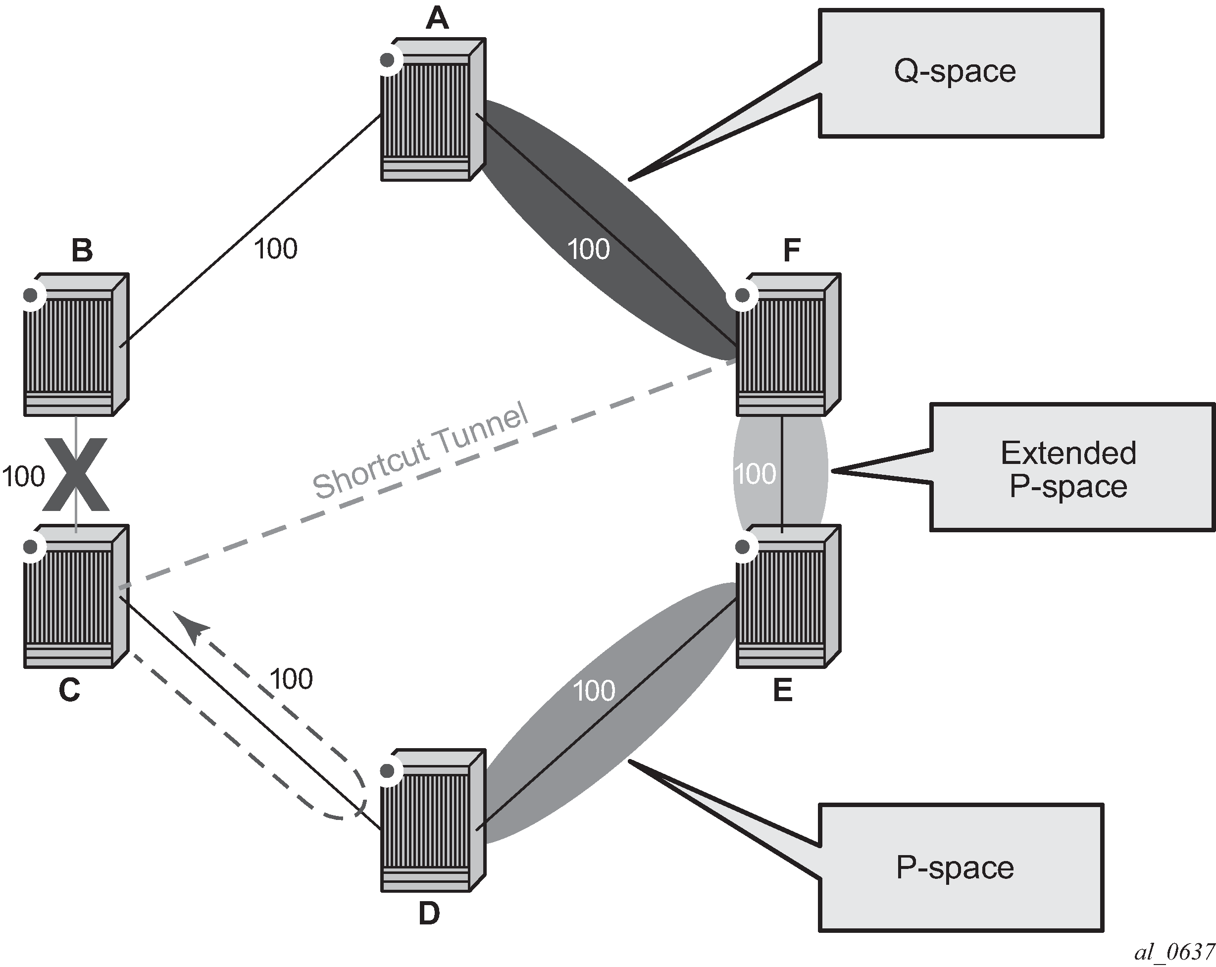
When the LFA SPF in node C computes the per-prefix LFA next hop, prefixes which use link C-B as the primary next hop has no LFA next hop because of the ring topology. If node C used node link C-D as a back-up next hop, node D would loop a packet back to node C. The remote LFA then runs the following algorithm, referred to as the PQ Algorithm in RFC 7490.
-
Compute the extended P space of Node C with respect to link C-B. The extended P space is the set of nodes reachable from node C without any path transiting the protected link (link C-B). This computation yields nodes D, E, and F.
The determination of the extended P space by node C uses the same computation as the regular LFA by running SPF on behalf of each of the neighbors of C.
Note: RFC 7490 initially introduced the concept of P space, which would have excluded node F because, from the node C perspective, node C has a couple of ECMP paths, one of which goes via link C-B. However, because the remote LFA next hop is activated when link C-B fails, this rule can be relaxed and node F can be included, which then yields the extended P space.The user can limit the search for candidate P-nodes to reduce the number of SPF calculations in topologies where many eligible P-nodes can exist. Use the following commands to configure the maximum IGP cost from node C for a P-node to be eligible:
-
config>router>isis>loopfree-alternates remote-lfa max-pq-cost value
-
config>router>ospf>loopfree-alternates remote-lfa max-pq-cost value
-
-
Compute the Q space of node B with respect to link C-B. The Q space is the set of nodes from which the destination proxy (node B) can be reached without any path transiting the protected link (link C-B).
The Q space calculation is effectively a reverse SPF on node B. In general, one reverse SPF is run on behalf of each neighbor of C to protect all destinations resolving over the link to the neighbor. This yields nodes F and A in the example shown in Remote LFA algorithm.
The user can limit the search for candidate Q-nodes to reduce the number of SPF calculations in topologies where many eligible Q-nodes can exist. The CLI command in step 1 is also used to configure the maximum IGP cost from node C for a Q node to be eligible.
-
Select the best alternate node which is the intersection of extended P and Q spaces. The best alternate node or PQ-node is node F in the example of Remote LFA algorithm. From node F onwards, traffic follows the IGP shortest path.
If many PQ-nodes exist, the lowest IGP cost from node C is used to narrow down the selection; if more than one PQ-node remains, the node with lowest router ID is selected.
The details of the label stack encoding when the packet is forwarded over the remote LFA next hop is shown in Remote LFA next hop in segment routing.
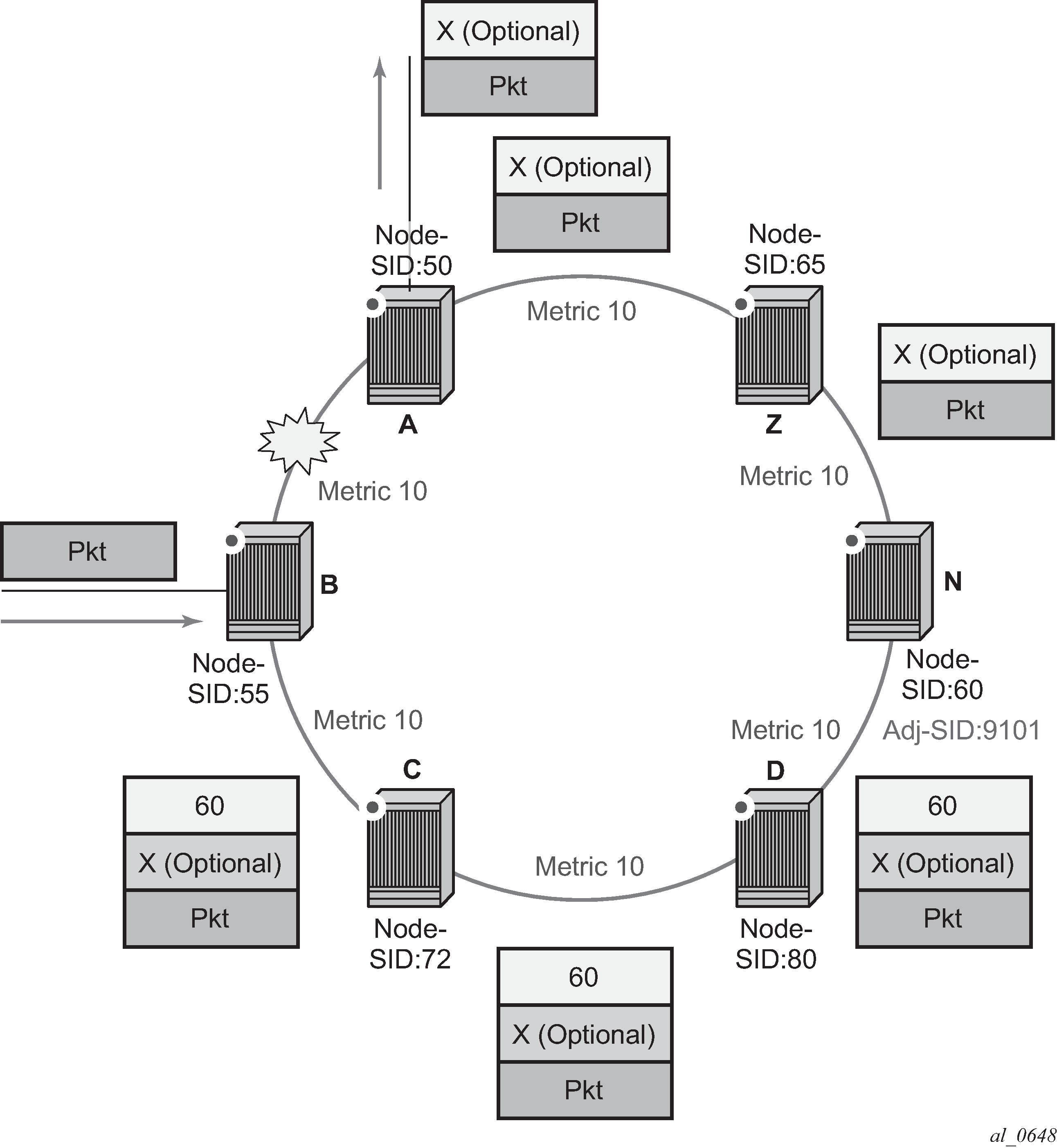
The label corresponding to the node SID of the PQ-node is pushed on top of the original label of the SID of the resolved destination prefix. If node C has resolved multiple node SIDs corresponding to different prefixes of the selected PQ-node, it pushes the lowest node SID label on the packet when forwarded over the remote LFA backup next-hop.
If the PQ-node is also the advertising router for the resolved prefix, the label stack is compressed in the following cases depending on the IGP:
-
In IS-IS, the label stack is always reduced to a single label, which is the label of the resolved prefix owned by the PQ-node.
-
In OSPF, the label stack is reduced to the single label of the resolved prefix when the PQ-node advertised a single node SID in this OSPF instance. If the PQ-node advertised a node SID for multiple of its loopback interfaces within this same OSPF instance, the label stack is reduced to a single label only in the case where the SID of the resolved prefix is the lowest SID value.
The following rules and limitations apply to the remote LFA implementation:
-
If the user excludes a network IP interface from being used as an LFA next hop using the CLI command loopfree-alternate-exclude under the IS-IS or OSPF context of the interface, the interface is also excluded from being used as the outgoing interface for a remote LFA tunnel next hop.
-
As with the regular LFA algorithm, the remote LFA algorithm computes a backup next hop to the ABR advertising an inter-area prefix and not to the destination prefix itself.
Topology independent LFA
The Topology-Independent LFA (TI-LFA) feature improves the protection coverage of a network topology by computing and automatically instantiating a repair tunnel to a Q node which is not in the shortest path from the computing node. The repair tunnel uses the shortest path to the P node and a source-routed path from the P node to the Q node.
In addition, the TI-LFA algorithm selects the backup path that matches the post-convergence path. This helps capacity planning in the network because traffic always flows on the same path when transitioning to the FRR next hop and then on to the new primary next hop.
At a high level, the TI-LFA link protection algorithm searches for the closest Q node to the computing node and then selects the closest P node to this Q node, up to a maximum number of labels. This is performed on each of the post-convergence paths to each destination node or prefix D.
When the TI-LFA feature is enabled in IS-IS, it provides a TI-LFA link-protect backup path in IS-IS MT=0 for an SR-ISIS IPV4/IPv6 tunnel (node SID and adjacency SID), for an IPv4 SR-TE LSP, and for LDP IPv4 FEC when the LDP fast-reroute backup-sr-tunnel option is enabled.
TI-LFA configuration
Users can enable TI-LFA in an IS-IS instance using the following command:
config>router>isis>loopfree-alternates [remote-lfa [max-pq-cost value]] [ti-lfa [max-sr-frr-labels value]]
When the ti-lfa option is enabled in IS-IS, it provides a TI-LFA link-protect backup path in IS-IS MT=0 for an SR-ISIS IPV4 and IPv6 tunnel (node SID and adjacency SID), for an IPv4 SR-TE LSP, and for an LDP IPv4 FEC when the LDP fast-reroute backup-sr-tunnel option is enabled. For more information about the applicability of the various LFA options, see LFA protection option applicability.
The value entered for max-sr-frr-labels parameter limits the search for the LFA backup next hop.
0
The IGP LFA SPF restricts the search to the TI-LFA backup next hop that does not require a repair tunnel, meaning that P node and Q node are the same and match a neighbor. This is also the case when both P and Q nodes match the advertising router for a prefix.
1 to 3
The IGP LFA SPF widens the search to include a repair tunnel to a P node which is connected to the Q nodes within zero-to-two hops for a total of maximum of three labels: one node SID to the P node and two adjacency SIDs from the P node to the Q node. If the P node is a neighbor of the computing node, its node SID is compressed, meaning that up to three adjacency SIDs can separate the P and Q nodes.
2 (default)
This corresponds to a repair tunnel to a non adjacent P which is adjacent to the Q node. If the P node is a neighbor of the computing node, then the node SID of the P node is compressed and the default value of two labels corresponds to two adjacency SIDs between the P and Q nodes.
When the user attempts to change the max-sr-frr-labels parameter to a value that results in a change to the computed FRR overhead, then IGP checks that all SR-TE LSPs can properly account for the overhead based on the configuration of the LSP max-sr-labels and additional-frr-labels parameter values. If they cannot, the change is rejected.
The FRR overhead is computed by IGP and its value is set as follows:
0 if segment-routing is disabled in the IGP instance
-
0 if segment-routing is enabled but remote-lfa is disabled and ti-lfa is disabled
-
1 if segment routing is enabled and remote-lfa is enabled but ti-lfa is disabled, or if segment-routing is enabled and remote-lfa is enabled and ti-lfa is enabled but ti-lfa max-sr-frr-labels labels is set to 0.
-
the value of ti-lfa max-sr-frr-labels labels, if segment-routing is enabled and ti-lfa is enabled regardless if remote-lfa is enabled or disabled.
TI-LFA link-protect operation
This section describes TI-LFA protection behavior when the loopfree-alternates command is enabled with the remote-lfa and ti-lfa options as described in TI-LFA configuration.
LFA protection option applicability
Depending on the configured options of the loopfree-alternates command, the LFA SPF in an IGP instance runs algorithms in the following order:
- The LFA SPF computes a regular LFA for each node and prefix. In this step, a computed backup next hop satisfies any applied LFA policy. This backup next hop protects that specific prefix or node in the context of IP FRR, LDP FRR, SR FRR, and SR-TE FRR.
-
The LFA SPF follows with the TI-LFA, if the ti-lfa option is
enabled for all prefixes and nodes, regardless of the outcome of the first step.
A prefix or node for which a TI-LFA backup next hop is found overrides the result from the first step in the context of LDP FRR in SR FRR and in SR-TE FRR if the LDP fast-reroute backup-sr-tunnel option is enabled.
With SR FRR and SR-TE FRR, the TI-LFA next hop protects the node-SID of that prefix and any adjacency-SID terminating on the node-SID of that prefix.
The prefix or node continues to use the backup next hop found in step1 in the context of LDP FRR (if the LDP fast-reroute backup-sr-tunnel option is disabled), or in IP FRR.
- The LFA SPF runs remote LFA only for the next hop of prefixes and nodes that remain unprotected after step1 and step 2 if the remote-lfa option is enabled. A prefix or node for which a remote LFA backup next hop is found uses it in the context of LDP FRR in SR FRR and in SR-TE FRR when the LDP fast-reroute backup-sr-tunnel option is enabled.
To protect an adjacency SID, the LFA selection algorithm uses the following preference order:
-
adjacency of an alternate parallel link to the same neighbor.
If more than one adjacency exists, select one as follows:
-
adjacency with the lowest metric
-
adjacency to the neighbor with the lowest router ID (OSPF) or system-id (IS-IS), and the lowest metric
-
with the lowest interface index and the lowest router ID (OSPF) or system-id (IS-IS)
-
-
an ECMP next hop to a node-SID of the same neighbor that is different from the next hop of the protected adjacency.
If more than one next hop exists, select one as follows:
-
next hop with the lowest metric
-
next hop to the neighbor with the lowest router ID (OSPF) or system-id (IS-IS) if same lowest metric
-
next hop to the lowest interface index if same neighbor router ID (OSPF) or system-id (IS-IS)
-
-
LFA backup outcome of a node SID of the same neighbor. The following is the preference order:
-
TI-LFA backup
-
LFA backup
-
RLFA backup
-
TI-LFA algorithm
At a high level, the TI-LFA link protection algorithm searches for the closest Q node to the computing node and then selects the closest P node to this Q node, up to a number of labels corresponding to the value of ti-lfa max-sr-frr-labels labels, on each of the post-convergence paths to each destination node or prefix D. Consider the topology in Selecting link-protect TI-LFA backup path where router R3 computes a TI-LFA next hop for protecting link R3-R4.
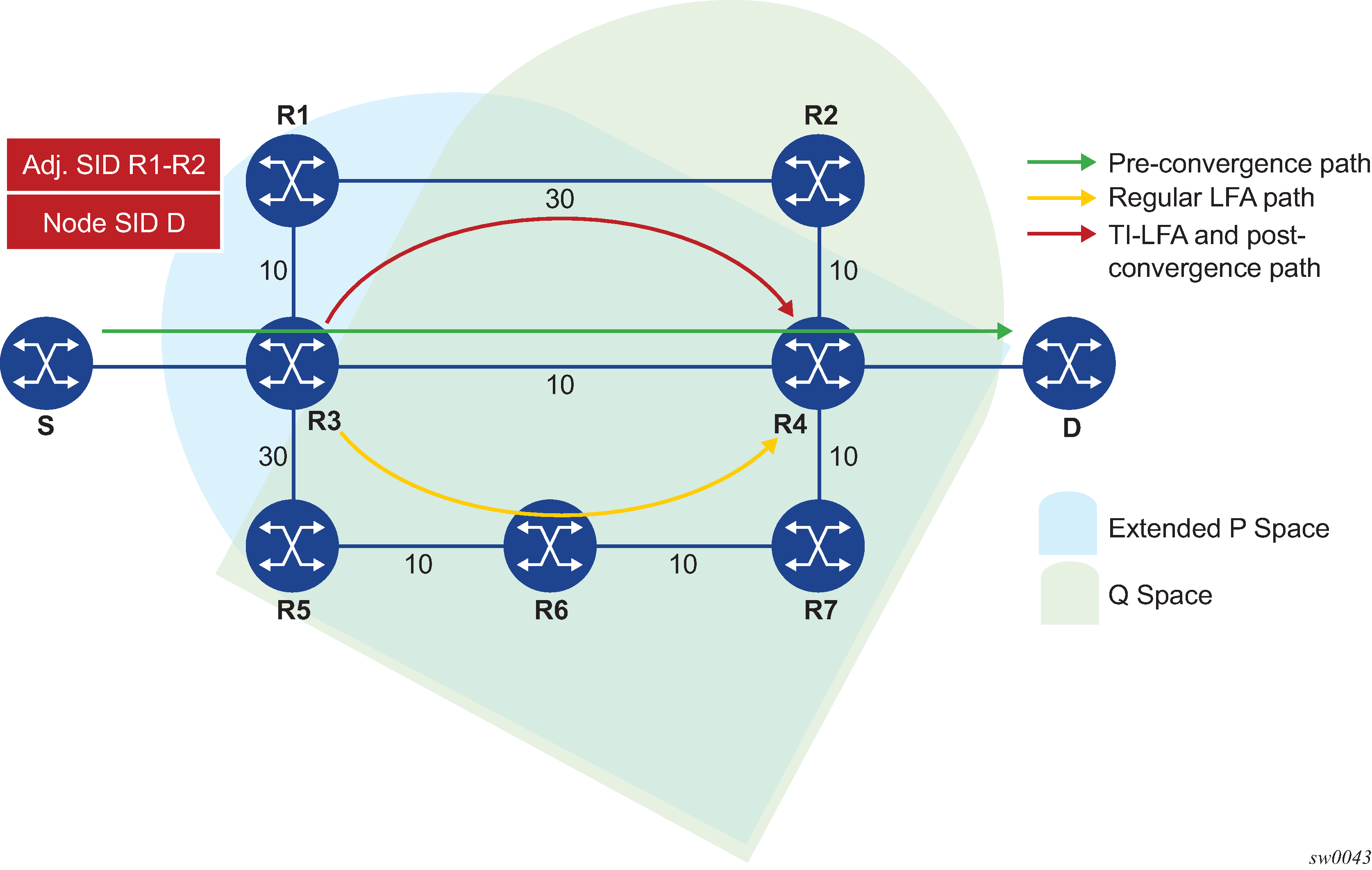
For each destination node D:
-
Compute the post-convergence SPF on the topology without the protected link.
In Selecting link-protect TI-LFA backup path, R3 finds a single post-convergence path to destination D via R1.
Note: The post-convergence SPF does not include IGP shortcut. -
Compute the extended P-Space of R3 with respect to protected link R3-R4 on the post-convergence paths.
This is the set of nodes Yi in the post-convergence paths which are reachable from R3 neighbors without any path transiting the protected link R3-R4.
R3 computes an LFA SPF rooted at each of its neighbors within the post-convergence paths, that is, R1, using the following equation:
Distance_opt(R1, Yi) < Distance_opt(R1, R3) + Distance_opt(R3,
                            Yi)
Where, Distance_opt(A,B) is the shortest distance between A and B. The extended P-space calculation yields only node R1.
-
Compute Q-space of R3 with respect to protected link R3-R4 in the post-convergence paths.
This is the set of nodes Zi in the post-convergence paths from which the neighbor node R4 of the protected link, acting as a proxy for all destinations D, can be reached without any path transiting the protected link R3-R4.
Distance_opt(Zi, R4) < Distance_opt(Zi, R3) + Distance_opt(R3,
                            R4)
The Q-space calculation yields nodes R2 and R4.
This is the same computation of the Q-space performed by the remote LFA algorithm, except that the TI-LFA Q-space computation is performed only on the post-convergence.
-
For each post-convergence path, search for the closest Q-node and select the closest P-node to this Q-node, up to a number of labels corresponding to the value of ti-lfa max-sr-frr-labels labels.
In the topology in Selecting link-protect TI-LFA backup path, there is a single post-convergence path, a single P-node (R1), and the closest of the two found Q-nodes to the P-Node is R2.
R3 installs the repair tunnel to the P-Q set and includes the node-SID of R1 and the adjacency SID of the adjacency over link R1-R2 in the label stack. Note that because the P-node R1 is a neighbor of the computing node R3, the node SID of R1 is not needed and the label stack of the repair tunnel is compressed to the adjacency SID over link R1-R2 as shown in Selecting link-protect TI-LFA backup path.
When a P-Q set is found on multiple ECMP post-convergence paths, the following selection rules are applied, in ascending order, to select a set from a single path:
-
the lowest number of labels
-
the next hop to the neighbor router with the lowest router-id (OSPF) or system-id (ISIS)
-
the next hop corresponding to the Q node with the lowest router-id (OSPF) or system-id (ISIS)
If multiple links with adjacency SID exist between the selected P node and the selected Q node, the following rules are used to select one of them:
-
the adjacency SID with the lowest metric
-
the adjacency SID with the lowest SID value if same lowest metric
-
TI-LFA feature interaction and limitations
The following are feature interactions and limitations of the TI-LFA link protection.
Enabling the ti-lfa option in an IS-IS or OSPF instance overrides the user configuration of the loopfree-alternate-exclude command under the interface’s context in that IGP instance. In other words, the TI-LFA SPF uses that interface as a backup next hop if it matches the post-convergence next hop.
-
Any prefix excluded from LFA protection using the loopfree-alternates exclude prefix-policy prefix-policy command under the IGP instance context is also excluded from TI-LFA.
-
Because the post-convergence SPF does not use paths transiting on a node in IS-IS overload, the TI-LFA backup path automatically does not transit on the A node.
-
IES interfaces are skipped in TI-LFA computation because they do not support Segment Routing with MPLS encapsulation. If the only found TI-LFA backup next hop matches an IES interface, IGP treats this as if there were no TI-LFA backup paths and falls back to using either a remote LFA or regular LFA backup path as per the selection rules in LFA protection option applicability.
-
The TI-LFA feature provides link-protection only. Thus, if the protected link is a broadcast interface, the TI-LFA algorithm only guarantees protection of that link and not of the Pseudo-Node (PN) corresponding to that shared subnet. In other words, if the PN is in the post-convergence path, the TI-LFA backup path may still traverse again the PN. For example, node E in TI-LFA backup path via a Pseudo-Node computes a TI-LFA backup path to destination D via E-C-PN-D because it is the post-convergence path when excluding link E-PN from the topology. This TI-LFA backup does not protect against the failure of the PN.
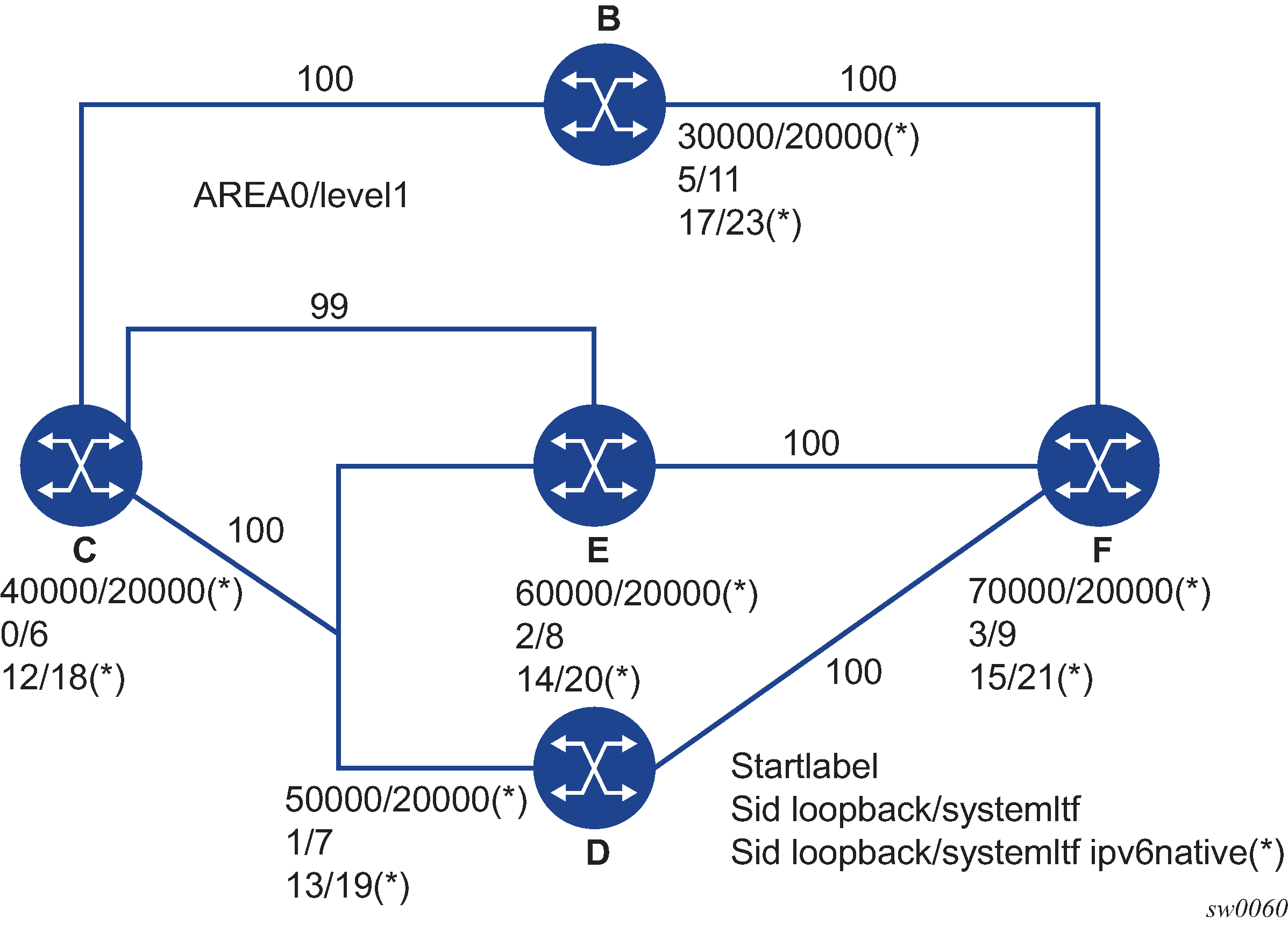
When the computing router selects an adjacency SID among a set of parallel adjacencies between the P and Q nodes, the selection rules in step 4 of TI-LFA algorithm are used. However, these rules may not yield the same interface the P node itself would have selected in its post-convergence SPF because the latter is based on the lowest value of the locally managed interface index.
For example, node A in Parallel adjacencies between P and Q nodes computes the link-protect TI-LFA backup path for destination node E as path A-C-E, where C is the P node and E is the Q node and destination. C has a pair of adjacency SIDs with the same metric to E. Node A selects the adjacency over the P2P link C-E because it has the lowest SID value but node C may select the interface C-PN in its post-convergence path calculation if that interface has a lower interface index than P2P link C-E.
Figure 8. Parallel adjacencies between P and Q nodes 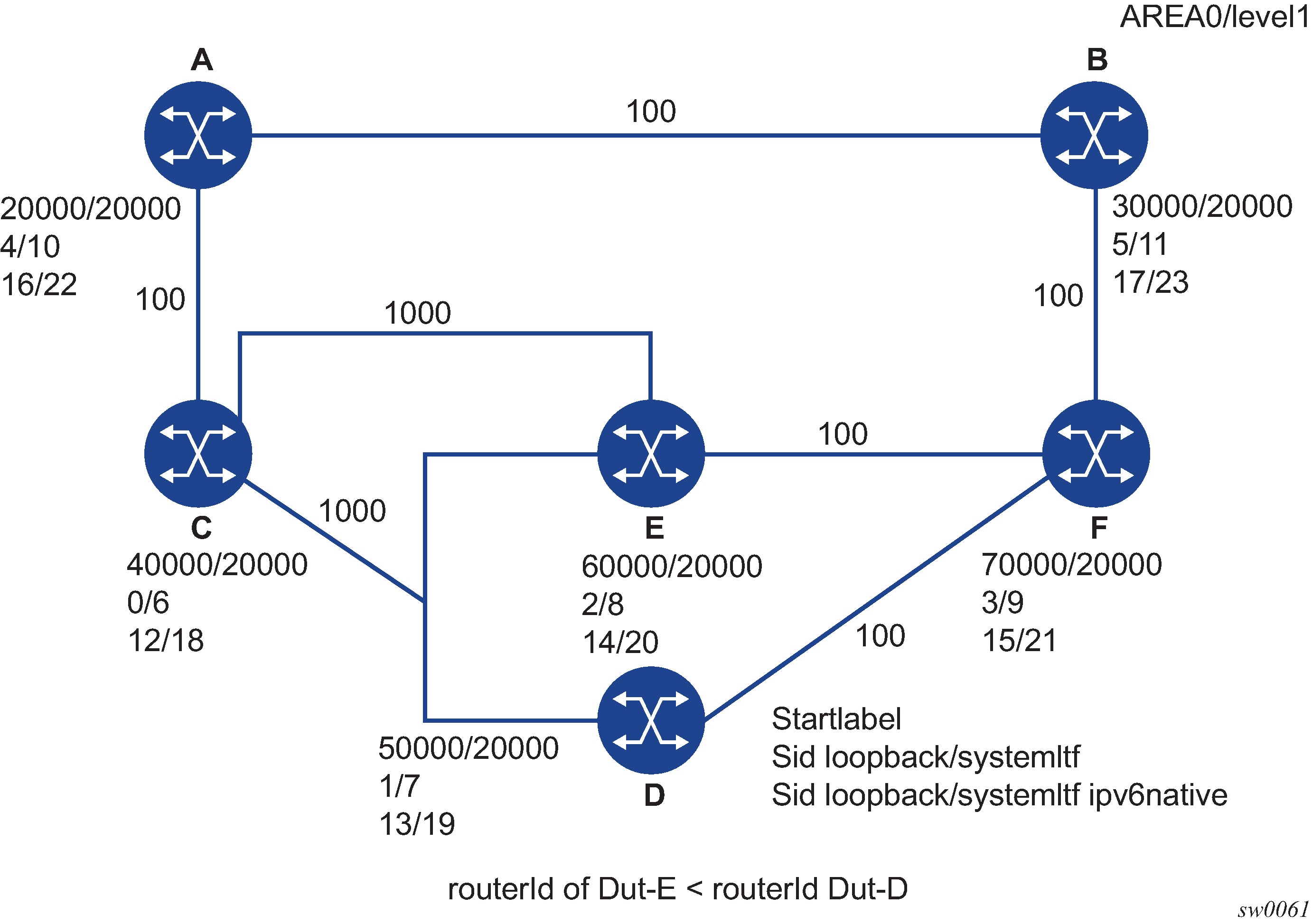
-
When a node SID is advertised by multiple routers (anycast SID), the TI-LFA algorithm on a router which resolves the prefix of this SID computes the backup next hop toward a single node owner of the prefix based on the rules for prefix and SID ECMP next-hop selection.
Datapath support
The TI-LFA repair tunnel can have a maximum of three additional labels pushed in addition to the label of the destination node or prefix. The user can set a lower maximum value for the additional FRR labels by configuring the ti-lfa max-sr-frr-labels labels CLI option. The default value is 2.
The datapath models the backup path like a SR-TE LSP and therefore uses a super-NHLFE pointing to the NHLFE of the first hop in the repair tunnel. That first hop corresponds to either an adjacency SID or a node SID of the P node.
There is the special case where the P node is adjacent to the node computing the TI-LFA backup, and the Q node is the same as the P node or adjacent to the P node. In this case, the datapath at the computing router pushes either zero labels or one label for the adjacency SID between P and Q nodes. The backup path uses a regular NHLFE in this case like in base LFA or remote LFA features. Selecting link-protect TI-LFA backup path shows and example of a single label in the backup NHLFE.
Node protection support in TI-LFA and remote LFA
This feature extends the Remote LFA and TI-LFA features by adding support for node protection. The extensions are additions to the original link-protect LFA SPF algorithm.
When node protection is enabled, the router prefers a node-protect over a link-protect repair tunnel for a prefix if both are found in the Remote LFA or TI-LFA SPF computations. This feature protects against the failure of a downstream node in the path of the prefix of a node SID except for the node owner of the node SID.
Feature configuration
The following are the CLI commands to configure the remote LFA and TI-LFA node protection feature.
configure
        — router
            — [no] isis
                — [no] loopfree-alternates
                    — [no] remote-lfa [max-pq-cost 0 to 4294967295, default=4261412864]
                        — [no] node-protect [max-pq-nodes 1 to 32, default=16]
                    — [no] ti-lfa [max-sr-frr-labels 0 to 3, default=2]
                        — [no] node-protect
                    — exclude
                        — [no] prefix-policy prefix-policy [prefix-policy…(up to 5 max)]
                    — exit
                — exit
A command is added to enable node-protect calculation to both Remote LFA (node-protect [max-pq-nodes <1 to 32, default=16>]) and TI-LFA (node-protect).
When the node-protect command is enabled, the router prefers a node-protect over a link-protect repair tunnel for a prefix if both are found in the Remote LFA or TI-LFA SPF computations. The SPF computations may only find a link-protect repair tunnel for prefixes owned by the protected node. This feature protects against the failure of a downstream node in the path of the prefix of a node SID except for the node owner of the node SID.
The parameter max-pq-nodes in Remote LFA controls the maximum number of candidate PQ nodes found in the LFA SPFs for which the node protection check is performed. As described in Remote LFA node-protect operation, the node-protect condition means the router must run the original link-protect Remote LFA algorithm plus one extra forward SPF on behalf of each PQ node found, potentially after applying the max-pq-cost parameter, to check if the path from the PQ node to the destination does not traverse the protected node. Setting this parameter to a lower value means the LFA SPFs uses less computation time and resources but may result in not finding a node-protect repair tunnel. The default value is 16.
TI-LFA node-protect operation
The SR OS supports the node-protect extensions to the TI-LFA algorithm as described in draft-bashandy-rtgwg-segment-routing-ti-lfa-05.
Application of the TI-LFA algorithm for node protection shows a simple topology to illustrate the operation of the node-protect in the TI-LFA algorithm.
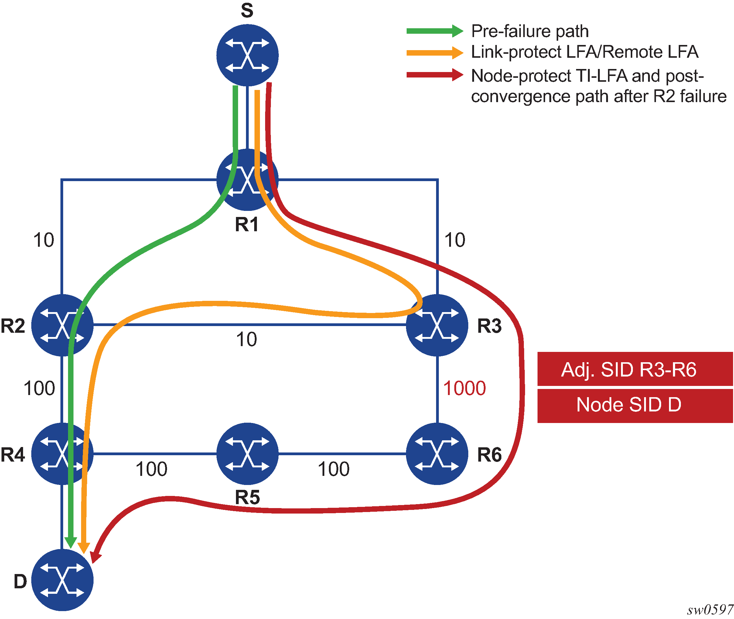
The first change is that the algorithm has to protect a node instead of a link.
The following topology computations pertain to Application of the TI-LFA algorithm for node protection:
For each destination prefix D, R1 programs the TI-LFA repair tunnel (max-sr-frr-labels=1):
-
For prefixes other than those owned by node R2 and R3, R1 programs a node-protect repair tunnel to the P-Q pair R3-R6 by pushing the SID of adjacency R3-R6 on top of the SID for destination D and programming a next hop of R3.
-
For prefixes owned by node R2, R1 runs the link-protect TI-LFA algorithm and programs a simple link-protect repair tunnel which consists of a backup next hop of R3 and pushing no additional label on top of the SID for the destination prefix.
-
Prefixes owned by node R3 are not impacted by the failure of R2 because their primary next hop is R3.
-
Compute post-convergence SPF on the topology without the
protected node.
In Application of the TI-LFA algorithm for node protection, R1 computes TI-LFA on the topology without the protected node R2 and finds a single post-convergence path to destination D via R3 and R6.
Prefixes owned by all other nodes in the topology have a post-convergence path via R3 and R6 except for prefixes owned by node R2. The latter uses the link R3-R2 and they can only benefit from link protection.
-
Compute extended P-Space of R1 with respect to protected node
R2 on the post-convergence paths.
This is the set of nodes Yi in the post-convergence paths that are reachable from R1 neighbors, other than protected node R2, without any path transiting the protected node R2.
R1 computes an LFA SPF rooted at each of its neighbors within the post-convergence paths, for example, R3, using the following equation:
Distance_opt(R3, Yi) < Distance_opt(R3, R2) +
                                            Distance_opt(R2, Yi)
Where:
Distance_opt(A,B) is the shortest distance between A and B.
The extended P-space calculation yields node R3 only.
-
Compute Q-space of R1 with respect to protected link R1-R2 on
the post-convergence paths.
This is the set of nodes Zi in the post-convergence paths from which node R2 can be reached without any path transiting the protected link R1-R2.
Distance_opt(Zi, R2) < Distance_opt(Zi, R1) +
                                            Distance_opt(R1, R2)
The reverse SPF for the Q-space calculation is the same as in the link-protect algorithm and uses the protected node R2 as the proxy for all destination prefixes. Note that if the Q-space were to be computed with respect to the protected node R2 instead of link R1-R2, a reverse SPF would have to be done to each destination D which is very costly and would not scale. Computing Q-space with respect to link R1-R2 however means the algorithm only guarantees the path from the computing node to the Q node is node-protecting. The path from the Q node to the destination Dis not guaranteed to avoid the protected node R2. The intersection of the Q-space with post-convergence path is modified in the next step to mitigate this risk.
This step yields nodes R3, R4, R5, and R6.
-
For each post-convergence path, search for the closest Q-node to destination D
and select the closest P-node to this Q-node, up to a number of labels
corresponding to the value of ti-lfa
max-sr-frr-labels labels.
This step yields the following P-Q sets depending on the value of the parameter max-sr-frr-labels:
-
max-sr-frr-labels=0, R3 is the closest Q node to the destination D and R3 is the only P node. This case is the one which results in link protection via PQ node R3.
-
max-sr-frr-labels=1, R6 is the closest Q node to the destination D and R3 is the only P node. The repair tunnel for this case uses the SID of the adjacency over link R3-R6 and is illustrated in Application of the TI-LFA algorithm for node protection.
-
max-sr-frr-labels=2, R5 is the closest Q node to the destination D and R3 is the only P node. The repair tunnel for this case uses the SIDs of the adjacencies over links R3-R6 and R6-R5.
-
max-sr-frr-labels=3, R4 is the closest Q node to the destination D and R3 is the only P node. The repair tunnel for this case uses the SIDs of the adjacencies over links R3-R6, R6-R5, and R5-R4.
Note this step of the algorithm is modified from link protection which prefers Q nodes which are the closest to the computing router R1. This is to minimize the probability that the path from the Q node to the destination D goes via the protected node R2 as described in step 2. There is however still a probability that the found P-Q set achieves link protection only.
-
-
Select the P-Q Set.
If a candidate P-Q set is found on each of the multiple ECMP post-convergence paths in step 4, the following selection rules are applied in ascending order to select a single set:
-
lowest number of labels
-
lowest next-hop router ID
-
lowest interface index if same next-hop router ID
If multiple parallel links with adjacency SID exist between the P and Q nodes of the selected P-Q set, the following rules are used to select one of them:
-
Adjacency SID with lowest metric
-
Adjacency SID with the lowest SID value if same lowest metric
-
Remote LFA node-protect operation
SR OS supports the node-protect extensions to the Remote LFA algorithm as described in RFC 8102.
Remote LFA follows a similar algorithm as TI-LFA but does not limit the scope of the calculation of the extended P-Space and of the Q-Space to the post-convergence paths.
Remote LFA adds an extra forward SPF on behalf of the PQ node to ensure that for each destination the selected PQ node does not use a path via the protected node.
Application of the remote LFA algorithm for node protection shows a slightly modified topology from that in TI-LFA feature interaction and limitations. A new node R7 is added to the top ring and the metric for link R3-R6 is modified to 100.
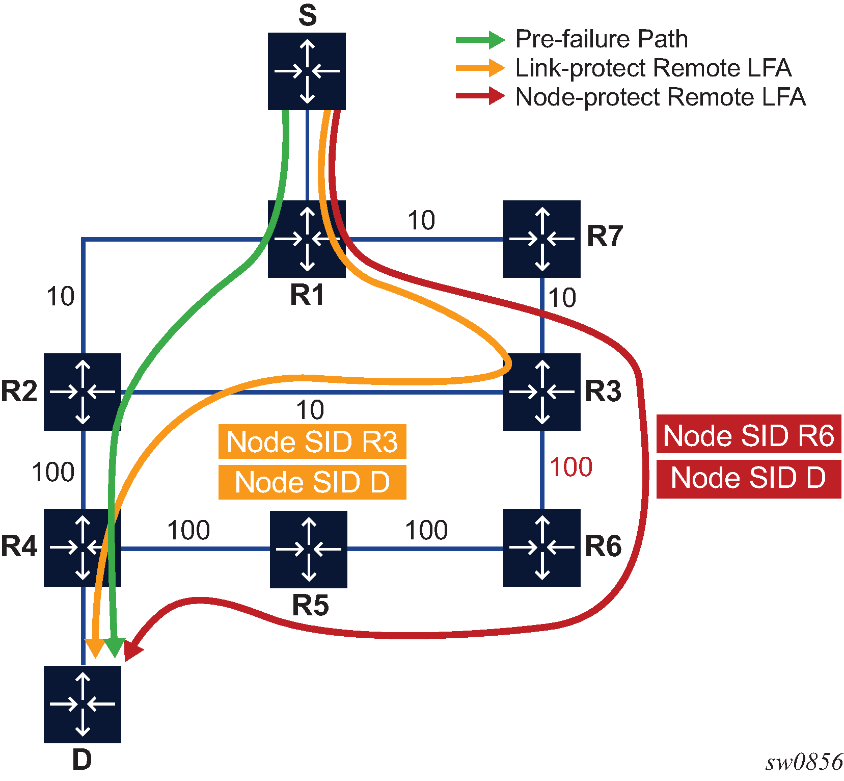
Applying the node protect remote LFA algorithm to this topology yields the following steps:
-
Compute extended P-Space of R1 with respect to protected node
R2.
This is the set of nodes Yi which are reachable from R1 neighbors, other than protected node R2, without any path transiting the protected node R2.
R1 computes a LFA SPF rooted at each of its neighbors, in this case, R7, using the following equation:
Distance_opt(R7, Yi) < Distance_opt(R7, R2) +
                                            Distance_opt(R2, Yi)
Where Distance_opt(A,B) is the shortest distance between A and B.
Nodes R7, R3 and R6 satisfy this inequality.
-
Compute Q-space of R1 with respect to protected link
R1-R2.
This is the set of nodes Zi from which node R2 can be reached without any path transiting the protected link R1-R2.
Distance_opt(Zi, R2) < Distance_opt(Zi, R1) +
                                            Distance_opt(R1, R2)
The reverse SPF for the Q-space calculation is the same as in the remote LFA link-protect algorithm and uses the protected node R2 as the proxy for all destination prefixes.
This step yields nodes R3, R4, R5, and R6.
Therefore, the candidate PQ nodes after this step are nodes R3 and R6.
-
For each PQ node found, run a forward SPF to each destination
D.
This step is required to select only the subset of PQ nodes which does not traverse protected node R2.
Distance_opt(PQi, D) < Distance_opt(PQi, R2) +
                                            Distance_opt(R2, D)
Of the candidates PQ nodes R3 and R6, only PQ node R6 satisfies this inequality.
Note this step of the algorithm is applied to the subset of candidate PQ nodes out of steps 1 and 2 and to which the parameter max-pq-cost was already applied. This subset is further reduced in this step by retaining the candidate PQ nodes which provide the highest coverage among all protected nodes in the topology and which number does not exceed the value of parameter max-pq-nodes.
In case of multiple candidate PQ nodes out of this step, the detailed selection rules of a single PQ node from the candidate list is provided in Step4.
-
Select a PQ Node.
If multiple PQ nodes satisfy the criteria in all the above steps, then R1 further selects the PQ node as follows:
-
R1 selects the lowest IGP cost from R1.
-
If more than one remains, R1 selects the PQ node reachable via the neighbor with the lowest router ID (OSPF) or system-id (ISIS).
-
If more than one remains, R1 selects the PQ node with the lowest router ID (OSPF) or system-id (ISIS).
-
For each destination prefix D, R1 programs the remote LFA backup path:
-
For prefixes of R5, R4 or downstream of R4, R1 programs a node-protect remote LFA repair tunnel to the PQ node R6 by pushing the SID of node R6 on top of the SID for destination D and programming a next hop of R7.
-
For prefixes owned by node R2, R1 runs the link-protect remote LFA algorithm and programs a simple link-protect repair tunnel which consists of a backup next hop of R7 and pushing the SID of PQ node R3 on top of the SID for the destination prefix D.
-
Prefixes owned by nodes R7, R3, and R6 are not impacted by the failure of R2 because their primary next hop is R7.
TI-LFA and remote LFA node protection feature interaction and limitations
LFA protection option applicability describes the order of activation of the various LFA types on a per prefix basis: TI-LFA, followed by base LFA, followed by remote LFA.
Node protection is enabled for TI-LFA and remote LFA separately. The base LFA prefers node protection over link protection.
The order of activation of the LFA types supersedes the protection type (node versus link). Consequently, it is possible that a prefix can be programmed with a link-protect backup next hop by the more preferred LFA type. For example, a prefix is programmed with the only link-protect backup next hop found by the base LFA while there exists a node-protect remote LFA next hop.
LFA policies
Application of LFA policy to a segment routing node SID tunnel
When a route next-hop policy template is applied to an interface, the LFA backup selection algorithm is extended to also apply to IPv4/IPv6 SR-ISIS, and IPv4 SR-OSPF node-SID tunnels in which a primary next hop is reachable using that interface. The extension applies to base LFA, Remote LFA (RLFA), and Topology-Independent LFA (TI-LFA).
The following general rules apply across all LFA methods:
The LFA policy constraints admin-group (include-group and exclude-group) and SRLG (srlg-enable) are only checked against the outgoing interface used by the LFA/RLFA/TI-LFA backup path.
The LFA policy parameter protection-type {link | node}, which controls the preference among link and node protection backup types, applies to all LFA methods.
Base LFA automatically computes both protection types but prefers, on a prefix basis, link-protect over node-protect backup next hop by default.
By default, RLFA and TI-LFA only perform link-protect backup path computation unless the optional command node-protect is enabled, in which case, the preference is reversed.
For all three LFA methods, when the LFA policy enables a preference for link-protect or node-protect, the backup path is selected from the computed paths based on the configuration for the individual LFA method protection preference and the outcome (node-protect or link-protect) of the actual computation within each method. Note, however, that on a per-destination prefix basis, the post-convergence constraint of TI-LFA is selected over the LFA protection type in all cases. The selection rule uses the TI-LFA backup (if one exists), even if it is of a less-preferred protection type than the one backup path computed by base LFA and RLFA.
For example, assume that an LFA policy with protection-type=node is applied to an ISIS interface and the node-protect command is enabled in both RLFA and TI-LFA contexts in this ISIS instance. If TI-LFA found a link-protect backup path for the destination prefix of a SR-ISIS tunnel, it is always selected over the base LFA node-protect and RLFA node-protect backup paths.
The outcomes of LFA policy selections for specified destination prefixes of SR tunnels are summarized in Outcome of LFA policy with protection-type=node and Outcome of LFA policy with protection-type=link .
Table 1. Outcome of LFA policy with protection-type=node RLFA outcome LFA policy protection-type=node Base LFA (LFA) outcome none link-protect node-protect TI-LFA outcome TI-LFA outcome TI-LFA outcome none link-protect node-protect none link-protect node-protect none link-protect node-protect —
—
TI-LFA
TI-LFA
LFA
TI-LFA
TI-LFA
LFA
TI-LFA
TI-LFA
link-protect
RLFA
TI-LFA
TI-LFA
LFA
TI-LFA
TI-LFA
LFA
TI-LFA
TI-LFA
node-protect
RLFA
TI-LFA
TI-LFA
RLFA
TI-LFA
TI-LFA
LFA
TI-LFA
TI-LFA
Table 2. Outcome of LFA policy with protection-type=link RLFA outcome LFA policy protection-type=link Base LFA (LFA) outcome none link-protect node-protect TI-LFA outcome TI-LFA outcome TI-LFA outcome none link-protect node-protect none link-protect node-protect none link-protect node-protect —
—
TI-LFA
TI-LFA
LFA
TI-LFA
TI-LFA
LFA
TI-LFA
TI-LFA
link-protect
RLFA
TI-LFA
TI-LFA
LFA
TI-LFA
TI-LFA
LFA
TI-LFA
TI-LFA
node-protect
RLFA
TI-LFA
TI-LFA
LFA
TI-LFA
TI-LFA
LFA
TI-LFA
TI-LFA
LFA policy parameter nh-type {ip | tunnel}, which controls preference among the backup of type IP and type tunnel (IGP shortcut), is not applicable to RLFA and TI-LFA backup paths.
However, the parameter applies if the LFA policy results in selecting a base LFA backup and the user-enabled resolution of SR-ISIS or SR-OSPF tunnel over IGP shortcut using RSVP-TE LSP.
When configured on an interface, the route next-hop policy template applies to destination prefixes of:
IPv4 and IPv6 SR-ISIS node SID tunnels
IPv4 SR-OSPF node SID tunnels
where the primary next hop is reachable using that interface
The route next-hop policy template also indirectly applies to:
IPv4 or IPv6 SR-TE LSPs
IPv4 or IPv6 SR policies that use any of the previously mentioned SR tunnels as the top SID in their SID list
Finally, the LFA policy indirectly applies to IPv4 LDP FECs when the LDP fast-reroute backup-sr-tunnel option is enabled and the FEC is protected with a SR tunnel.
An LFA policy, applied to an interface cannot be selectively enabled or disabled per LFA method.
As a result of these rules, at most one backup path remains in each LFA method. In that case, the selection preference is as follows:
TI-LFA backup IP next hop or repair tunnel
Base LFA backup next hop
This can be of type IP (default or if nh-type type preference set to ip) or of type tunnel (nh-type type preference is set to tunnel and family SRv4 or SRv6 resolves to IGP shortcut using RSVP-TE LSP).
Remote LFA repair tunnel
Application of LFA policy to adjacency SID tunnel
The modifications to TI-LFA and RLFA as described in Application of LFA policy to a segment routing node SID tunnel are also applied to adjacency SID tunnel in a similar fashion.
The LFA selection algorithm for an adjacency to a neighbor is modified by applying the LFA policy of the link of the protected adjacency. It adheres to the following preference order:
Adjacency of an alternate parallel link to the same neighbor, determined as follows:
apply admin-group and SRLG constraints of the LFA policy of the link of the protected adjacency
select the adjacency with best admin-groups according to the preference specified in the value of the include-group option in the route next-hop policy template
select the adjacency with lowest metric
select the adjacency to the neighbor with the lowest router ID (OSPF) or system ID (IS-IS), and the lowest metric
select the adjacency over the lowest interface index, and the lowest neighbor router ID (OSPF) or system ID (IS-IS)
ECMP next hop to a node-SID of the same neighbor, determined as follows:
apply admin-group and SRLG constraints of the LFA policy of the link of the protected adjacency
select the next hop with the best admin-groups according to the preference specified in the value of the include-group option in the route next-hop policy template
select the next hop with lowest metric
select the next hop to the neighbor with the lowest router ID (OSPF) or system ID (ISIS), and the lowest metric
select the next hop over the lowest interface index, and the lowest neighbor router ID (OSPF) or system ID (IS-IS)
LFA backup outcome of a node SID of the same neighbor:
select a LFA backup with an outgoing link that does not conflict with the LFA policy of the link of the protected adjacencyNote: If a different LFA policy was already applied in the computation of the LFA backup of the node SID of the neighbor, it is possible that some links to that node SID may have been eliminated before applying the LFA policy of the link of the protected adjacency.
Application of LFA policy to backup node SID tunnel
The backup node SID feature allows OSPF to use the path to an alternate ABR as an RLFA backup for forwarding packets of prefixes outside the local area or domain when the path to the primary ABR fails.
This feature reduces the label stack size by omitting the PQ node label if a regular RLFA algorithm is run.
The backup node SID algorithm consists of the following steps:
-
Perform an SPF on the modified topology with the primary ABR
removed.
This action resolves the backup node SID using the path to the alternate ABR.
- Install the ILM to use the backup node SID for transit traffic with the maximum ECMP next hops found in step 1.
-
Use the backup node SID as an RLFA backup for prefixes outside the local area
or domain. This step is modified as follows to select the backup node SID by
applying the LFA policy corresponding the primary next hop of these prefixes, as
follows.
-
For each neighbor (Ni) found in step 1, use the LFA policy to select the best next-hop interface.
-
Among the remaining interfaces, use the LFA policy to select best (Ni) and select its interface.
Note: A backup node SID is always preferred to a regular RLFA backup. This does not change after applying the LFA policy because the main objective of the backup node SID feature is to reduce the label stack size of the backup tunnel. -
Configuration example of LFA policy use in remote LFA and TI-LFA
The following figure shows an example network topology that uses the OSPF routing protocol and in which the user assigns an SRLG ID to each group of OSPF links to represent fate-sharing among the links in the group. Assume the router ecmp value is set to 1.
The user wants to enforce that the LFA backup computed and programmed by each node for a specific destination prefix avoids the SRLG ID of the primary next hop of that prefix. To that effect, the user applies an LFA policy to each link that is used as a primary next hop to reach destination prefixes.
For example, node F uses the top interface to node C as the primary next hop for the SR-OSPF tunnel to the SID of node C. The LFA policy states that the LFA backup must exclude outgoing interfaces that are members of the SRLG ID of the interface of the primary next hop. Therefore, node F must select an LFA backup that avoids SRLG ID=SrlgGroup_1.
Node F enables base LFA, remote LFA with node-protect, and TI-LFA with node-protect on the OSPF routing instance. The LFA SPF yields the following candidate LFA backup paths for the tunnel to the SID of node C.
Base LFA returns two backup paths: next hop over the second interface to C (cost 10) and next hop over the interface to node E (cost 20).
After applying the LFA policy, only next hop over the interface to node E (cost 20) remains. The second interface to node C is also a member of SRLG ID=SrlgGroup_1 and, therefore, the LFA next hop using it is excluded.
TI-LFA returns a single backup path: the next hop over the second interface to C (cost 10).
After applying the LFA policy, no LFA backup path remains.
Remote LFA returns two backup paths, one backup path by PQ node C over the second interface to C (cost 10) and one by PQ node E over the interface to node E (cost 20).
After applying the LFA policy, only the backup path by PQ node E over the interface to node E (cost 20) remains.
The LFA backup paths found by all three LFA methods are only link-protecting because node C is a neighbor of node F.
The final outcome is the selection among the LFA methods and base LFA is preferred to RLFA; therefore, the next hop over the interface to node E (cost 20) is selected and programmed by node F as the backup path for the SR-OSPF tunnel to the SID of node C.
The adjacency from node F to node C over first interface to node C also inherits the same LFA backup path as the node SID of C because the same LFA policy applies.
The following are excerpts of the CLI configuration of node F in this specific example. The commands relevant to the LFA policy applied to link F-C are identified by arrows.
In addition, the output of show commands in node F highlights both the primary and the link-protect base LFA backup for both the node SID tunnel to C and the adjacency SID tunnel over the first interface to node C.
Because C is the termination for both its node SID and the adjacency SID tunnels from node F, only link protection can be provided as shown by the output of tools>dump>router>ospf sr-database command (field L(R)). However, the output of the same show command for the tunnel to the SID of node D indicates the base LFA backup over the direct interface to node D is node-protecting (field Tn(R)).
*A:Dut-F>config>router# info
----------------------------------------------
#--------------------------------------------------
echo "IP Configuration"
#--------------------------------------------------
if-attribute <-------
srlg-group "SrlgGroup_1" value 1 <-------
srlg-group "SrlgGroup_2" value 2
srlg-group "SrlgGroup_3" value 3
exit
route-next-hop-policy <-------
begin <-------
template "templateSrlgGroup_1" <-------
srlg-enable
exit
template "templateSrlgGroup_2"
srlg-enable
exit
template "templateSrlgGroup_3"
srlg-enable
exit
commit
exit
interface "DUTF_TO_DUTC.1.0" <-------
address 1.0.36.6/24
secondary 51.0.36.6/24
port 1/1/4:1
mac 00:00:00:00:00:06
ipv6
address 3ffe::100:2406/120 primary-preference 1
address 3ffe::3300:2406/120 primary-preference 2
exit
if-attribute <-------
srlg-group "SrlgGroup_1" <-------
exit
no shutdown
exit
interface "DUTF_TO_DUTC.2.0" <-------
address 2.0.36.6/24
secondary 52.0.36.6/24
port 1/1/4:2
mac 00:00:00:00:00:06
ipv6
address 3ffe::200:2406/120 primary-preference 1
address 3ffe::3400:2406/120 primary-preference 2
exit
if-attribute <-------
srlg-group "SrlgGroup_1" <-------
exit
no shutdown
exit
interface "DUTF_TO_DUTD.1.0"
address 1.0.46.6/24
secondary 51.0.46.6/24
port 1/1/1:1
mac 00:00:00:00:00:06
ipv6
address 3ffe::100:2e06/120 primary-preference 1
address 3ffe::3300:2e06/120 primary-preference 2
exit
if-attribute
srlg-group "SrlgGroup_2"
exit
no shutdown
exit
interface "DUTF_TO_DUTD.2.0"
address 2.0.46.6/24
secondary 52.0.46.6/24
port 1/1/1:2
mac 00:00:00:00:00:06
ipv6
address 3ffe::200:2e06/120 primary-preference 1
address 3ffe::3400:2e06/120 primary-preference 2
exit
if-attribute
srlg-group "SrlgGroup_2"
exit
no shutdown
exit
interface "DUTF_TO_DUTE.1.0" <-------
address 1.0.56.6/24
secondary 51.0.56.6/24
port 1/1/2:1
mac 00:00:00:00:00:06
ipv6
address 3ffe::100:3806/120 primary-preference 1
address 3ffe::3300:3806/120 primary-preference 2
exit
if-attribute <-------
srlg-group "SrlgGroup_3" <-------
exit
no shutdown
exit
interface "DUTF_TO_DUTE.2.0" <-------
address 2.0.56.6/24
secondary 52.0.56.6/24
port 1/1/2:2
mac 00:00:00:00:00:06
ipv6
address 3ffe::200:3806/120 primary-preference 1
address 3ffe::3400:3806/120 primary-preference 2
exit
if-attribute <-------
srlg-group "SrlgGroup_3" <-------
exit
no shutdown
exit
interface "loopbackF.1.0"
address 1.0.66.6/32
secondary 51.0.66.6/32
loopback
ipv6
address 3ffe::100:4206/128 primary-preference 1
address 3ffe::3300:4206/128 primary-preference 2
exit
no shutdown
exit
interface "loopbackF.2.0"
address 2.0.66.6/32
secondary 52.0.66.6/32
loopback
ipv6
address 3ffe::200:4206/128 primary-preference 1
address 3ffe::3400:4206/128 primary-preference 2
exit
no shutdown
exit
interface "system"
address 10.20.1.6/32
ipv6
address 3ffe::a14:106/128
exit
no shutdown
exit
ip-fast-reroute
router-id 10.20.1.6
#--------------------------------------------------
echo "MPLS Label Range Configuration"
#--------------------------------------------------
mpls-labels
sr-labels start 20000 end 80000
exit
#--------------------------------------------------
echo "OSPFv2 Configuration"
#--------------------------------------------------
ospf 0 10.20.1.6
traffic-engineering
database-export identifier 0
advertise-router-capability area
loopfree-alternates <-------
remote-lfa <-------
node-protect <-------
exit <-------
ti-lfa max-sr-frr-labels 3 <-------
node-protect <-------
exit <-------
exit <-------
segment-routing
prefix-sid-range start-label 70000 max-index 999
egress-statistics
adj-set
adj-sid
node-sid
exit
ingress-statistics
adj-set
adj-sid
node-sid
exit
no shutdown
exit
area 0.0.0.0
interface "system"
node-sid index 9
no shutdown
exit
interface "DUTF_TO_DUTC.1.0" <-------
interface-type point-to-point
hello-interval 2
dead-interval 10
metric 10
lfa-policy-map route-nh-template "templateSrlgGroup_1" <-------
no shutdown
exit
interface "DUTF_TO_DUTD.1.0"
interface-type point-to-point
hello-interval 2
dead-interval 10
metric 1000
lfa-policy-map route-nh-template "templateSrlgGroup_2"
no shutdown
exit
interface "DUTF_TO_DUTE.1.0"
interface-type point-to-point
hello-interval 2
dead-interval 10
metric 10
lfa-policy-map route-nh-template "templateSrlgGroup_3"
no shutdown
exit
interface "loopbackF.1.0"
node-sid index 3
no shutdown
exit
interface "DUTF_TO_DUTC.2.0"
interface-type point-to-point
hello-interval 2
dead-interval 10
metric 10
lfa-policy-map route-nh-template "templateSrlgGroup_4"
no shutdown
exit
interface "DUTF_TO_DUTD.2.0"
interface-type point-to-point
hello-interval 2
dead-interval 10
metric 1000
lfa-policy-map route-nh-template "templateSrlgGroup_5"
no shutdown
exit
interface "DUTF_TO_DUTE.2.0"
interface-type point-to-point
hello-interval 2
dead-interval 10
metric 10
lfa-policy-map route-nh-template "templateSrlgGroup_6"
no shutdown
exit
interface "loopbackF.2.0"
node-sid index 15
no shutdown
exit
exit
no shutdown
exit
----------------------------------------------
*A:Dut-F# tools dump router segment-routing tunnel
==============================================================================================
Legend: (B) - Backup Next-hop for Fast Re-Route
(D) - Duplicate
label stack is ordered from top-most to bottom-most
==============================================================================================
--------------------------------------------------------------------------------------------------+
Prefix |
Sid-Type Fwd-Type In-Label Prot-Inst |
Next Hop(s) Out-Label(s) Interface/Tunnel-ID |
--------------------------------------------------------------------------------------------------+
1.0.33.3 <-------
Node Orig/Transit 70000 OSPF-0 <-------
1.0.36.3 40000 DUTF_TO_DUTC.1.0 <-------
(B)1.0.56.5 60000 DUTF_TO_DUTE.1.0 <-------
1.0.44.4 <-------
Node Orig/Transit 70001 OSPF-0 <-------
1.0.36.3 40001 DUTF_TO_DUTC.1.0 <-------
(B)1.0.46.4 50001 DUTF_TO_DUTD.1.0 <-------
1.0.55.5
Node Orig/Transit 70002 OSPF-0
1.0.56.5 60002 DUTF_TO_DUTE.1.0
(B)1.0.36.3 40002 DUTF_TO_DUTC.1.0
1.0.66.6
Node Terminating 70003 OSPF-0
1.0.11.1
Node Orig/Transit 70004 OSPF-0
1.0.36.3 40004 DUTF_TO_DUTC.1.0
(B)1.0.46.4 50004 DUTF_TO_DUTD.1.0
1.0.22.2
Node Orig/Transit 70005 OSPF-0
1.0.36.3 40005 DUTF_TO_DUTC.1.0
(B)1.0.46.4 50005 DUTF_TO_DUTD.1.0
10.20.1.3
Node Orig/Transit 70006 OSPF-0
1.0.36.3 40006 DUTF_TO_DUTC.1.0
(B)1.0.56.5 60006 DUTF_TO_DUTE.1.0
10.20.1.4
Node Orig/Transit 70007 OSPF-0
1.0.36.3 40007 DUTF_TO_DUTC.1.0
(B)1.0.46.4 50007 DUTF_TO_DUTD.1.0
10.20.1.5
Node Orig/Transit 70008 OSPF-0
1.0.56.5 60008 DUTF_TO_DUTE.1.0
(B)1.0.36.3 40008 DUTF_TO_DUTC.1.0
10.20.1.6
Node Terminating 70009 OSPF-0
10.20.1.1
Node Orig/Transit 70010 OSPF-0
1.0.36.3 40010 DUTF_TO_DUTC.1.0
(B)1.0.46.4 50010 DUTF_TO_DUTD.1.0
10.20.1.2
Node Orig/Transit 70011 OSPF-0
1.0.36.3 40011 DUTF_TO_DUTC.1.0
(B)1.0.46.4 50011 DUTF_TO_DUTD.1.0
2.0.33.3
Node Orig/Transit 70012 OSPF-0
1.0.36.3 40012 DUTF_TO_DUTC.1.0
(B)1.0.56.5 60012 DUTF_TO_DUTE.1.0
2.0.44.4
Node Orig/Transit 70013 OSPF-0
1.0.36.3 40013 DUTF_TO_DUTC.1.0
(B)1.0.46.4 50013 DUTF_TO_DUTD.1.0
2.0.55.5
Node Orig/Transit 70014 OSPF-0
1.0.56.5 60014 DUTF_TO_DUTE.1.0
(B)1.0.36.3 40014 DUTF_TO_DUTC.1.0
2.0.66.6
Node Terminating 70015 OSPF-0
2.0.11.1
Node Orig/Transit 70016 OSPF-0
1.0.36.3 40016 DUTF_TO_DUTC.1.0
(B)1.0.46.4 50016 DUTF_TO_DUTD.1.0
2.0.22.2
Node Orig/Transit 70017 OSPF-0
1.0.36.3 40017 DUTF_TO_DUTC.1.0
(B)1.0.46.4 50017 DUTF_TO_DUTD.1.0
2.0.56.5
Adjacency Transit 524282 OSPF-0
2.0.56.5 3 DUTF_TO_DUTE.2.0
(B)1.0.56.5 3 DUTF_TO_DUTE.1.0
2.0.46.4
Adjacency Transit 524283 OSPF-0
2.0.46.4 3 DUTF_TO_DUTD.2.0
(B)1.0.36.3 40001 DUTF_TO_DUTC.1.0
2.0.36.3
Adjacency Transit 524284 OSPF-0
2.0.36.3 3 DUTF_TO_DUTC.2.0
(B)1.0.36.3 3 DUTF_TO_DUTC.1.0
1.0.56.5
Adjacency Transit 524285 OSPF-0
1.0.56.5 3 DUTF_TO_DUTE.1.0
(B)1.0.36.3 40002 DUTF_TO_DUTC.1.0
1.0.46.4
Adjacency Transit 524286 OSPF-0
1.0.46.4 3 DUTF_TO_DUTD.1.0
(B)1.0.36.3 40001 DUTF_TO_DUTC.1.0
1.0.36.3 <-------
Adjacency Transit 524287 OSPF-0 <-------
1.0.36.3 3 DUTF_TO_DUTC.1.0 <----
(B)1.0.56.5 60000 DUTF_TO_DUTE.1.0 <----
---------------------------------------------------------------------------------------------+
No. of Entries: 24
---------------------------------------------------------------------------------------------+
*A:Dut-F#
*A:Dut-F# tools dump router ospf sr-database
===============================================================================
Rtr Base OSPFv2 Instance 0 Segment Routing Database
===============================================================================
SID Label St Type Prefix Stitching
AdvRtr Area Flags FRR
-------------------------------------------------------------------------------
0 70000 +R T1 1.0.33.3/32 - <-------
10.20.1.3 0.0.0.0 [NnP ] L(R) <-------
1 70001 +R T1 1.0.44.4/32 - <-------
10.20.1.4 0.0.0.0 [NnP ] Tn(R) <-------
2 70002 +R T1 1.0.55.5/32 -
10.20.1.5 0.0.0.0 [NnP ] L(R)
3 70003 +R LT1 1.0.66.6/32 -
10.20.1.6 0.0.0.0 [NnP ] -
4 70004 +R T1 1.0.11.1/32 -
10.20.1.1 0.0.0.0 [NnP ] Tn(R)
5 70005 +R T1 1.0.22.2/32 -
10.20.1.2 0.0.0.0 [NnP ] Tn(R)
6 70006 +R T1 10.20.1.3/32 -
10.20.1.3 0.0.0.0 [NnP ] L(R)
7 70007 +R T1 10.20.1.4/32 -
10.20.1.4 0.0.0.0 [NnP ] Tn(R)
8 70008 +R T1 10.20.1.5/32 -
10.20.1.5 0.0.0.0 [NnP ] L(R)
9 70009 +R LT1 10.20.1.6/32 -
10.20.1.6 0.0.0.0 [NnP ] -
10 70010 +R T1 10.20.1.1/32 -
10.20.1.1 0.0.0.0 [NnP ] Tn(R)
11 70011 +R T1 10.20.1.2/32 -
10.20.1.2 0.0.0.0 [NnP ] Tn(R)
12 70012 +R T1 2.0.33.3/32 -
10.20.1.3 0.0.0.0 [NnP ] L(R)
13 70013 +R T1 2.0.44.4/32 -
10.20.1.4 0.0.0.0 [NnP ] Tn(R)
14 70014 +R T1 2.0.55.5/32 -
10.20.1.5 0.0.0.0 [NnP ] L(R)
15 70015 +R LT1 2.0.66.6/32 -
10.20.1.6 0.0.0.0 [NnP ] -
16 70016 +R T1 2.0.11.1/32 -
10.20.1.1 0.0.0.0 [NnP ] Tn(R)
17 70017 +R T1 2.0.22.2/32 -
10.20.1.2 0.0.0.0 [NnP ] Tn(R)
-------------------------------------------------------------------------------
No. of Entries: 18
-------------------------------------------------------------------------------
St: R:reported I:incomplete W:wrong N:not reported F:failed
+:SR-ack -:no route
Type: L:local M: mapping Srv Tx: route type
FRR: L:Lfa R:RLfa T:TiLfa (R):Reported (F):Failed
Ln, Rn, Tn: FRR providing node-protection
===============================================================================
*A:Dut-F#
LFA protection using segment routing backup node SID
One of the challenges in MPLS deployments across multiple IGP areas or domains, such as in seamless MPLS design, is the provisioning of FRR local protection in access and metro domains that make use of a ring, a square, or a partial mesh topology. To implement IP, LDP, or SR FRR in these topologies, the remote LFA feature must be implemented. Remote LFA provides a Segment Routing (SR) tunneled LFA next hop for an IP prefix, an LDP tunnel, or an SR tunnel. For prefixes outside of the area or domain, the access or aggregation router must push four labels: service label, BGP label for the destination PE, LDP/RSVP/SR label to reach the exit ABR/ASBR, and one label for the remote LFA next hop. Small routers deployed in these parts of the network have limited MPLS label stack size support.
Label stack for remote LFA in ring topology illustrates the label stack required for the primary next hop and the remote LFA next hop computed by aggregation node AGN2 for the inter-area prefix of a remote PE. For an inter-area BGP label unicast route prefix for which ABR1 is the primary exit ABR, AGN2 resolves the prefix to the transport tunnel of ABR1 and therefore, uses the remote LFA next hop of ABR1 for protection. The primary next hop uses two transport labels plus a service label. The remote LFA next hop for ABR1 uses PQ node AGN5 and pushes three transport labels plus a service label.
Seamless MPLS with FRR requires up to four labels to be pushed by AGN2, as shown in Label stack for remote LFA in ring topology.
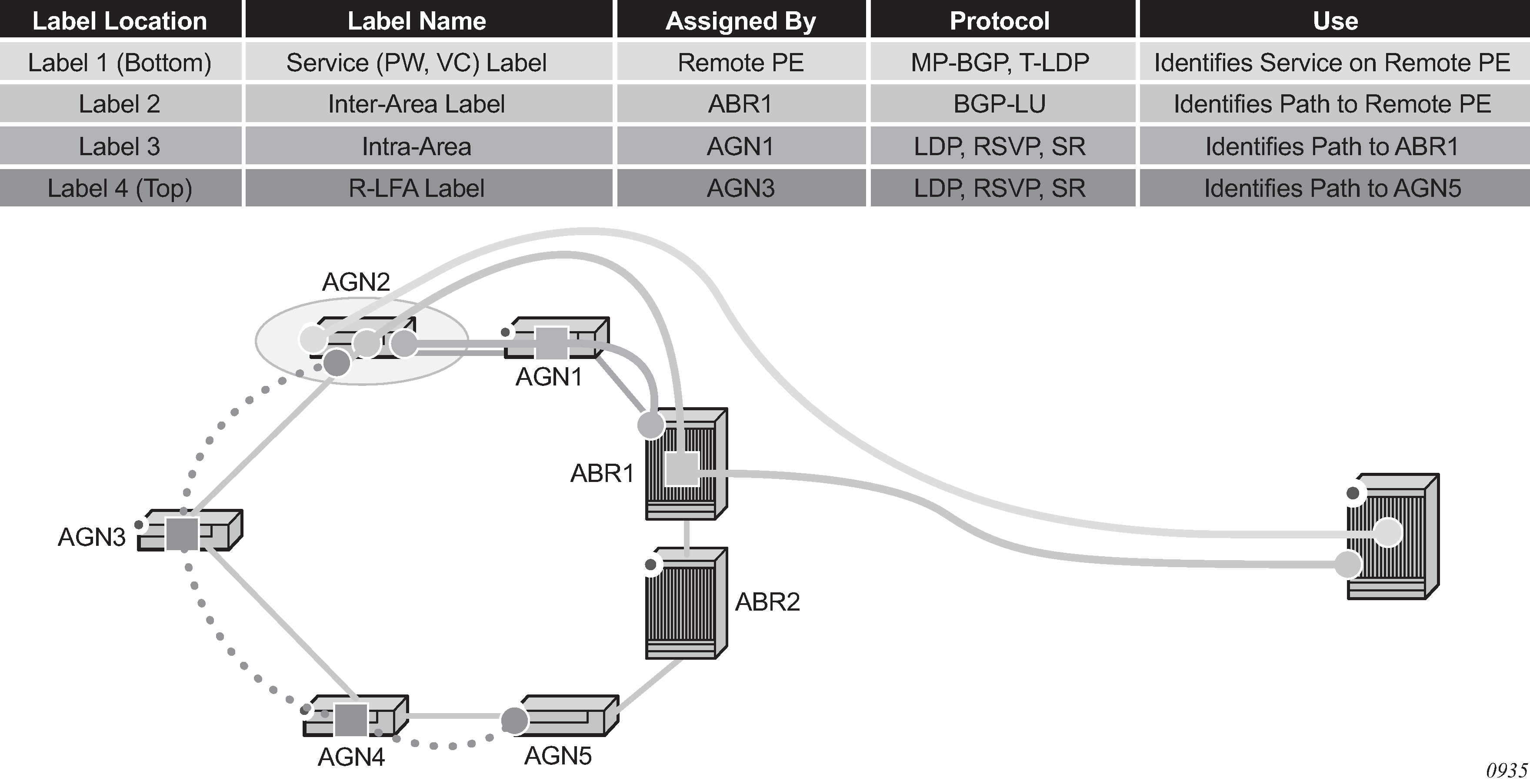
The objective of the LFA protection with a backup node SID feature is to reduce the label stack pushed by AGN2 for BGP label unicast inter-area prefixes. When link AGN2-AGN1 fails, packets are directed away from the failure and forwarded toward ABR2, which acts as the backup for ABR1 (and the other way around when ABR2 is the primary exit ABR for the BGP label unicast inter-area prefix). This requires that ABR2 advertise a special label for the loopback of ABR1 that attracts packets normally destined for ABR1. These packets are forwarded by ABR2 to ABR1 via the inter-ABR link.
As a result, AGN2 pushes the label advertised by ABR2 to back up ABR1 on top of the BGP label for the remote PE and the service label. This ensures that the label stack of the LFA next hop is the same size as that of the primary next hop and of the remote LFA next hop for the local prefix within the ring.
Configuring LFA using backup node SID in OSPF
LFA using a backup node SID is enabled by configuring a backup node SID at an ABR/ASBR that acts as a backup to the primary exit ABR/ASBR of inter-area/inter-as routes learned as BGP labeled routes.
config>router>ospf>segment-routing$
        — backup-node-sid ip-prefix/prefix-length index 0..4294967295
        — backup-node-sid ip-prefix/prefix-length label 1..4294967295
The user can enter either a label or an index for the backup node SID.
Detailed operation of LFA protection using backup node SID
As shown in Backup ABR node SID, LFA for seamless MPLS supports environments where the boundary routers are either:
ABR nodes that connect with Interior Border Gateway Protocol (IBGP) multiple domains, each using a different area of the same IGP instance
ASBR nodes that connect domains running different IGP instances and use IBGP within a domain and External Border Gateway Protocol (EBGP) to the other domains
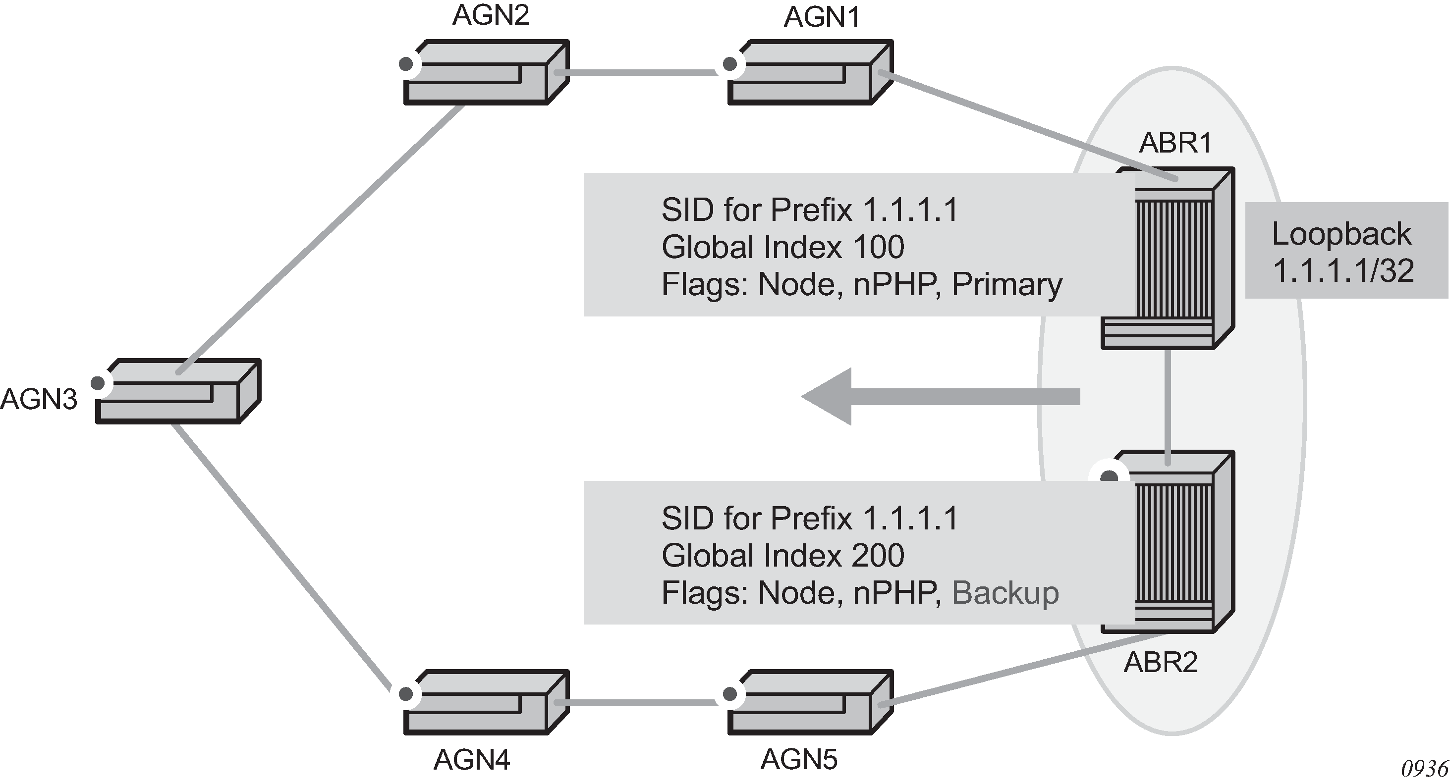
The following steps describe the configuration and behavior of LFA Protection using Backup Node SID:
The user configures node SID 100 in ABR1 for its loopback prefix 1.1.1.1/32. This is the regular node SID. ABR1 advertises the prefix SID sub-TLV for this node SID in the IGP and installs the ILM using a unique label.
Each router receiving the prefix sub-TLV for node SID 100 resolves it as described in Segment routing in shortest path forwarding. Changes to the programming of the backup NHLFE of node SID 100 based on receiving the backup node SID for prefix 1.1.1.1/32 are defined in Duplicate SID handling.
The user configures a backup node SID 200 in ABR2 for the loopback 1.1.1.1/32 of ABR1. The SID value must be different from that assigned by ABR1 for the same prefix. ABR2 installs the ILM, which performs a swap operation from the label of SID 200 to that of SID 100. The ILM must point to a direct link and next hop to reach 1.1.1.1/32 of ABR1 as its primary next hop. The IGP examines all adjacencies established in the same area as that of prefix 1.1.1.1/32 and determines which ones have ABR1 as a direct neighbor and with the best cost. If more than one adjacency has the best cost, the IGP selects the one with the lowest interface index. If there is no adjacency to reach ABR2, the prefix SID for the backup node is flushed and is not resolved. This is to prevent any other non-direct path being used to reach ABR1. As a result, any received traffic on the ILM of SID 200 traffic is blackholed.
If resolved, ABR2 advertises the prefix SID sub-TLV for this backup node SID 200 and indicates in the SR Algorithm field that a modified SPF algorithm, referred to as ‟Backup-constrained-SPF”, is required to resolve this node SID.
Each router receiving the prefix sub-TLV for the backup node SID 200 performs the following steps:
Note: The following resolution steps do not require a CLI command to be enabled.-
The router determines which router is being backed up. This is achieved by checking the router ID owner of the prefix sub-TLV that was advertised with the same prefix but without the backup flag and which is used as the best route for the prefix. In this case, it should be ABR1. Then the router runs a modified SPF by removing node ABR1 from the topology to resolve the backup node SID 200. The primary next hop should point to the path to ABR2 in the counter clockwise direction of the ring.
The router does not compute an LFA or a remote LFA for node SID 200 because the main SPF used a modified topology.
-
The router installs the ILM and primary NHLFE for the backup node SID.
Only a swap label operation is configured by all routers for the backup node SID. There is no push operation, and no tunnel for the backup node SID is added into the TTM.
-
The router programs the backup node SID as the LFA backup for the SR tunnel to node SID of 1.1.1.1/32 of ABR1. In other words, each router overrides the remote LFA backup for prefix 1.1.1.1/32, which is normally PQ node AGN5.
-
If the router is adjacent to ABR1, for example AGN1, it also programs the backup node SID as the LFA backup for the protection of any adjacency SID to ABR1.
-
When node AGN2 resolves a BGP label route for an inter-area prefix for which the primary ABR exit router is ABR1, it uses the backup node SID of ABR1 as the remote LFA backup instead of the SID to the PQ node (AGN5 in this example) to save on the pushed label stack.
AGN2 continues to resolve the prefix SID for any remote PE prefix that is summarized into the local area of AGN2 as usual. AGN2 programs a primary next hop and a remote LFA next hop. Remote LFA uses AGN5 as the PQ node and pushes two labels, as it would for an intra-area prefix SID. There is no need to use the backup node SID for this prefix SID and force its backup path to go to ABR1. The backup path may exit from ABR2 if the cost from ABR2 to the destination prefix is shorter.
If the user excludes a link from LFA in the IGP instance (config>router>ospf>area>interface>loopfree-alternate-exclude), a backup node SID that resolves to that interface is not used as a remote LFA backup in the same way as regular LFA or PQ remote LFA next hop behavior.
If the OSPF neighbor of a router is put into overload or if the metric of an OSPF interface to that neighbor is set to LSInfinity (0xFFFF), a backup node SID that resolves to that neighbor is not used as a remote LFA backup in the same way as regular LFA or PQ remote LFA next hop behavior.
LFA policy is supported with a backup node SID. See Application of LFA policy to backup node SID tunnel.
Duplicate SID handling
When the IGP issues or receives an LSA/LSP containing a prefix SID sub-TLV for a node SID or a backup node SID with a SID value that is a duplicate of an existing SID or backup node SID, the resolution in Handling of duplicate SIDs is followed.
OSPF control plane extensions
All routers supporting OSPF control plane extensions must advertise support of the new algorithm ‟Backup-constrained-SPF” by setting the value of the Algorithm bit to 2 in the SR Algorithm TLV, which is advertised in the Router Information Opaque LSA. This is in addition to the default supported algorithm ‟IGP-metric-based-SPF” of value 0. The following shows the encoding of the prefix SID sub-TLV to indicate a node SID of type backup and to indicate the modified SPF algorithm in the SR Algorithm field. The values used in the Flags field and in the Algorithm field are SR OS proprietary.
The new Algorithm (0x2) field and values are used by this feature.
0                   1                   2                   3
    0 1 2 3 4 5 6 7 8 9 0 1 2 3 4 5 6 7 8 9 0 1 2 3 4 5 6 7 8 9 0 1
   +-+-+-+-+-+-+-+-+-+-+-+-+-+-+-+-+-+-+-+-+-+-+-+-+-+-+-+-+-+-+-+-+
   |              Type             |             Length            |
   +-+-+-+-+-+-+-+-+-+-+-+-+-+-+-+-+-+-+-+-+-+-+-+-+-+-+-+-+-+-+-+-+
   |     Flags     |   Reserved    |      MT-ID    |Algorithm (0x2)|
   +-+-+-+-+-+-+-+-+-+-+-+-+-+-+-+-+-+-+-+-+-+-+-+-+-+-+-+-+-+-+-+-+
   |                     SID/Index/Label (variable)                |
   +-+-+-+-+-+-+-+-+-+-+-+-+-+-+-+-+-+-+-+-+-+-+-+-+-+-+-+-+-+-+-+-+
OSPF control plane extension fields lists OSPF control plane extension flag values.
| Field | Value |
|---|---|
Type |
2 |
Length |
variable |
Flags |
1 octet field |
The following flags are defined; the ‟B” flag is new:
     0  1  2  3  4  5  6  7
   +--+--+--+--+--+--+--+--+
   |  |NP|M |E |V |L | B|  |
   +--+--+--+--+--+--+--+--+
OSPF control plane extension flags describes OSPF control plane extension flags.
| Flag | Description |
|---|---|
NP-Flag |
No-PHP flag If set, the penultimate hop must not pop the prefix SID before delivering the packet to the node that advertised the prefix SID. |
M-Flag |
Mapping Server Flag If set, the SID is advertised from the Segment Routing Mapping Server functionality as described in RFC 8661. |
E-Flag |
Explicit-Null Flag If set, any upstream neighbor of the prefix SID originator must replace the prefix SID with a prefix SID having an Explicit-NULL value (0 for IPv4) before forwarding the packet. |
V-Flag |
Value/Index Flag If set, the prefix SID carries an absolute value. If not set, the prefix SID carries an index. |
L-Flag |
Local/Global Flag If set, the value/index carried by the prefix SID has local significance. If not set, then the value/index carried by this sub-TLV has global significance. |
B-Flag |
This flag is used by the Protection using backup node SID feature. If set, the SID is a backup SID for the prefix. This value is SR OS proprietary. |
Other bits |
Reserved These must be zero when sent and are ignored when received. |
MT-ID |
Multi-Topology ID, as defined in RFC 4915. |
Algorithm |
One octet identifying the algorithm the prefix SID is associated with. A value of (0x2) indicates the modified SPF algorithm, which removes from the topology the node that is backed up by the backup node SID. This value is SR OS proprietary. |
SID/Index/Label |
Based on the V and L flags, it contains either:
|
Multi-homed prefix LFA extensions in SR-OSPF
This feature makes use of the Multi-Homed Prefix (MHP) model described in RFC 8518 to compute a backup IP next-hop using an alternate ABR or ASBR for external prefixes and to an alternate router owner for local anycast prefixes.
The feature applies to OSPF routes of external /32 prefixes (OSPFv2 routes types 3, 4, 5, and 7) and local /32 anycast prefixes if the prefix is not protected by base LFA.
The computed IP next-hop based backup path is programmed for SR-OSPF node SID tunnels of external /32 prefixes and to /32 prefixes in same area as the computing node and which are advertised by multiple routers (anycast prefixes) in both algorithm 0 and flexible-algorithm numbers.
The details of the configuration of this feature are provided in the 7450 ESS, 7750 SR, 7950 XRS, and VSR Unicast Routing Protocols Guide section Multi-homed prefix LFA extensions in OSPF.
Multi-homed prefix LFA extensions in SR-ISIS and SRv6-ISIS
This feature makes use of the Multi-Homed Prefix (MHP) model described in RFC 8518 to compute a backup IP next-hop using an alternate ABR or ASBR for external prefixes and to an alternate router owner for local anycast prefixes.
The algorithm described in RFC 8518 is limited in scope to only computed backup paths consisting of direct IP next hops and tunneled next hops (IGP shortcuts).
The computed backup paths are added to IS-IS routes of external /32 and /128 prefixes and intra-area /32 and /128 anycast prefixes in the Routing Table Manager (RTM) if the prefix is not protected by a base LFA.
To have these backup paths programmed into the FIB, the following command must be enabled:
The computed backup path is also programmed for the following tunnels:
- SR-ISIS IPv4 and IPv6 node SID tunnels of external /32 and /128 prefixes and of intra-area /32 and /128 anycast prefixes, in both algorithm 0 and flexible algorithm numbers
- SRv6-ISIS locator routes and tunnels of external prefixes and of intra-area anycast prefixes of any size, in both algorithm 0 and flexible algorithm numbers
As a result, an SR-TE LSP, an SR-MPLS policy, or an SRv6 policy that uses an SR-ISIS SID or an SRv6-ISIS SID of those same prefixes in its configured or computed SID list benefits from the multihomed prefix LFA protection.
The details of the configuration for this feature are provided in the 7450 ESS, 7750 SR, 7950 XRS, and VSR Unicast Routing Protocols Guide section Multi-homed prefix LFA extensions in IS-IS.
LFA solution across IGP area or instance boundary using SR repair tunnel in SR-OSPF
This feature enhances the IP next-hop based MHP backup path calculation specified in RFC 8518 with the addition of the support of an SR repair tunnel. The SR repair tunnel uses a PQ node or a P-Q set to reach the alternate exit ABR or ASBR for external prefixes, or alternate owner router for intra-area anycast prefixes. This capability is in addition to supporting the RFC 8518 algorithm used in the case where the path to prefix P using the alternate exit ABR or ASBR (or alternate owner router) is in the shortest path from the neighbor of the computing node.
This feature applies the computed backup path to SR-OSPF node SID tunnels of external /32 prefixes and to /32 prefixes in the same area as the computing node, and which are advertised by multiple routers (anycast prefixes) in both algorithm 0 and flexible-algorithm numbers. It also extends the protection to any SR-TE LSP or SR policy that uses an SR-OSPF SID of those same prefixes in its configured or computed SID list.
This feature shares the same configuration CLI commands as the MHP LFA feature as described in Multi-homed prefix LFA extensions in SR-OSPF.
After the IP next-hop based MHP LFA is enabled, the extensions to compute an SR repair tunnel for the MHP LFA in the case of SR-OSPF are automatically enabled if the user enables TI-LFA or RLFA. The computation reuses the SID list of the primary path or of the TI-LFA or RLFA backup path of the alternate ABR, ASBR, or alternate owner router. The algorithm details are described in the following section.
Extending MHP LFA coverage with repair tunnels for SR OSPF
The following figures shows topology that is used as a reference in this section.
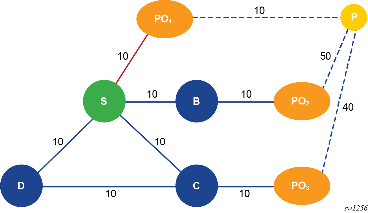
For computing node S, PO1 is the ABR in the best path (PObest) to reach prefix P. None of the neighbors of node S satisfies the link or node protection inequality of RFC 8518 described in the 7450 ESS, 7750 SR, 7950 XRS, and VSR Unicast Routing Protocols Guide section RFC 8518 multi-homed prefix LFA for OSPF. Therefore, the main aspect of the extension to the RFC 8518 algorithm is for node S to find the best repair tunnel using a PQ node or a P-Q set, which forwards the packet to an alternate exit ABR or ASBR represented by node PO1, PO2, or PO3 in Application of MHP LFA to SR-OSPF tunnel of external prefix.
The following are the steps of this algorithm:
-
Compute a multi-homed LFA repair tunnel for prefix P using each POi.
-
Create an ordered list of candidate MHP LFA tunnel paths with the following
preference order (from highest to lowest):
- Prefer the candidate path that uses a POi with the next hop of the primary path, avoiding neighbor node E. Candidate paths are split into two subsets and paths computed from step 1.a preferred over paths computed from step 1.b.
- Within each subset, prefer the candidate path that uses POi with lower total cost to prefix P expressed as Min{D_opt(S,POi) + cost(POi, P)}.
- If the cost is the same, prefer the candidate path that uses a POi with the lower label stack size.
- If the label stack size is the same, prefer the candidate path that uses a POi with the lower router ID.
- Analyze the ordered list and select the first MHP LFA tunnel path with a segment list size that does not exceed either the value of 1 if RLFA is enabled but TI-LFA is disabled, or the value of the loopfree-alternate ti-lfa max-sr-frr-labels command if TI-LFA is enabled.
- Program in data path the segment list of the selected MHP LFA repair tunnel for the specific prefix P. The segment list consists of pushing on top of the SID of destination prefix P the SID of the PQ node or the SIDs of the P-Q set.
Example application of MHP LFA with repair tunnel
The following figures shows topology that is used as a reference in this section.
Node S is connected to nodes E and N₁ using IP links, and to node N₂ using an IGP shortcut (RSVP-TE LSP).
Prefix P (6.6.6.6/32) is one of the following:
- an external prefix with prefix SID re-advertised by ASBR nodes PObest and PO₁ and with best path through PObest
- an anycast prefix with prefix SID owned by both routers PObest and PO1 with best path from node S is to PObest
An SRGB assigned to the OSPF instance uses an offset label value of 19000. Base LFA, RLFA, TI-LFA, and MHP LFA are all enabled in node S. Node protection is also enabled. MHP LFA is preferred. Therefore, the following CLI commands are enabled:
- classic CLI
- configure>router>ospf>loopfree-alternates>remote-lfa>node-protect
- configure>router>ospf>loopfree-alternates>ti-lfa>node-protect
- configure>router>ospf>loopfree-alternates>multi-homed-prefix>preference all
- MD CLI
- configure router ospf loopfree-alternate remote-lfa node-protect
- configure router ospf loopfree-alternate ti-lfa node-protect
- configure router ospf loopfree-alternate multi-homed-prefix preference all
The resulting LFA computations in node S for prefix P yield the following backup paths:
- base LFA node-protecting path to PObest and using IGP shortcut to neighbor N2 as next hop
- RLFA node-protecting path to PObest and transiting through PQ node N2
- TI-LFA node-protecting path to PObest and transiting through PQ node N2
-
a MHP LFA path using the RFC 8515 node-protecting inequality as described in the 7450 ESS, 7750 SR, 7950 XRS, and VSR Unicast Routing Protocols Guide section RFC 8518 multi-homed prefix LFA for OSPF. This yields the same path as the base LFA, meaning a node-protecting path to PObest and using IGP shortcut to neighbor N2 as the next hop.
Node S does, however, determine that this path does not satisfy the PObest overlap inequality as described in the 7450 ESS, 7750 SR, 7950 XRS, and VSR Unicast Routing Protocols Guide section Enhancement to RFC 8518 Algorithm for backup path overlap with path to PObest in the local area and, therefore, attempts an SR repair tunnel computation as the next step.
- MHP LFA path to PO1 and using IGP shortcut to neighbor N2 as next hop. This backup path forces the packet to arrive and exit (if P is external prefix) PO1 by pushing PO1 node SID with an index value of 60 and label value of 19060.
The MHP LFA repair tunnel is therefore the preferred backup path and is programmed in data path to protect the primary path of prefix P.
LFA solution across IGP area or instance boundary using SR repair tunnel in SR-ISIS and SRv6-ISIS
This feature enhances the backup path calculation for the IP next-hop based multihomed path prefix in RFC 8518 with the addition of repair tunnels that make use of a PQ node or a P-Q set to reach the alternate exit ABR or ASBR of external prefixes or the alternate owner router for intra-area anycast prefixes.
The feature programs the computed backup path for the following tunnels:
- SR-ISIS node SID tunnels of external /32 IPv4 prefixes and /128 IPv6 prefixes, and node SID tunnels of intra-area /32 IPv4 anycast prefixes and /128 anycast IPv6 prefixes, in both algorithm 0 and flexible-algorithms
- SRv6-ISIS locator routes and tunnels of external prefixes and of intra-area anycast prefixes of any size, in both algorithm 0 and flexible algorithm numbers
As a result, an SR-TE LSP, an SR-MPLS policy, or an SRv6 policy that uses an SR-ISIS SID or an SRv6-ISIS SID of those same prefixes in its configured or computed SID list benefits from the multihomed prefix LFA protection.
After the IP next-hop based multihomed prefix LFA is enabled, the extensions to compute a SR-TE repair tunnel for the multihomed prefix LFA in the case of SR-ISIS and SRv6-ISIS are automatically enabled if the user also enabled TI-LFA or Remote LFA. The computation reuses the SID list of the primary path or of the TI-LFA or Remote LFA backup path of the alternate ABR or ASBR or alternate owner router.
The behavior of this feature is the same as in OSPF. See LFA solution across IGP area or instance boundary using SR repair tunnel in SR-OSPF.
Segment routing data path support
A packet received with a label matching either a node SID or an adjacency SID is forwarded according to the ILM type and operation, as described in Data path support .
| Label type | Operation |
|---|---|
Top label is a local node SID |
Label is popped and the packet is further processed. If the popped node SID label is the bottom of stack label, the IP packet is looked up and forwarded in the appropriate FIB. |
Top or next label is a remote node SID |
Label is swapped to the calculated label value for the next hop and forwarded according to the primary or backup NHLFE. With ECMP, a maximum of 32 primary next-hops (NHLFEs) are programmed for the same destination prefix and for each IGP instance. ECMP and LFA next-hops are mutually exclusive as per existing implementation. |
Top or next label is an adjacency SID |
Label is popped and the packet is forwarded out on the interface to the next hop associated with this adjacency SID label. In effect, the data path operation is modeled like a swap to an implicit-null label instead of a pop. |
Next label is BGP 8277 label |
The packet is further processed according to the ILM operation as in current implementation.
|
Next label is a service label |
The packet is looked up and forwarded in the Layer 2 or VPRN FIB as in current implementation. |
A router forwarding an IP or a service packet over an SR tunnel pushes a maximum of two transport labels with a remote LFA next hop. This is illustrated in Transport label stack in shortest path forwarding with segment routing.
Assume that a VPRN service in node B forwards a packet received on a SAP to a destination VPN-IPv4 prefix X advertised by a remote PE2 via ASBR/ABR node A. Router B is in a segment routing domain while PE2 is in an LDP domain. BGP label routes are used to distribute the PE /32 loopbacks between the two domains.
When node B forwards over the primary next hop for prefix X, it pushes the node SID of the ASBR followed by the BGP 8277 label for PE2, followed by the service label for prefix X. When the remote LFA next hop is activated, node B pushes one or more segment routing label: the node SID for the remote LFA backup node (node N).
When node N receives the packet while the remote LFA next hop is activated, it pops the top segment routing label which corresponds to a local node SID. This results in popping this label and forwarding of the packet to the ASBR node over the shortest path (link N-Z).
When the ABR/ASBR node receives the packet from either node B or node Z, it pops the segment routing label which corresponds to a local node SID, then swaps the BGP label and pushes the LDP label of PE2 which is the next hop of the BGP label route.
Hash label and entropy label support
When the hash-label option is enabled in a service context, hash label is always inserted at the bottom of the stack as per RFC 6391.
The LSR adds the capability to check a maximum of 16 labels in a stack. The LSR is able to hash on the IP headers when the payload below the label stack of maximum size of 16 is IPv4 or IPv6, including when a MAC header precedes it (eth-encap-ip option).
The Entropy Label (EL) feature, as specified in RFC 6790, is supported on RSVP, LDP, segment-routed, and BGP transport tunnels. It uses the Entropy Label Indicator (ELI) to indicate the presence of the entropy label in the label stack. The ELI, followed by the actual entropy label, is inserted immediately below the transport label for which entropy label feature is enabled. If multiple transport tunnels have the entropy label feature enabled, the ELI/EL is inserted below the lowest transport label in the stack.
The LSR hashing operates as follows:
If the lbl-only hashing option is enabled, or if one of the other LSR hashing options is enabled but a IPv4 or IPv6 header is not detected below the bottom of the label stack, the LSR hashes on the EL only.
If the lbl-ip option is enabled, the LSR hashes on the EL and the IP headers.
If the ip-only or eth-encap-ip is enabled, the LSR hashes on the IP headers only.
For more information about the Hash Label and Entropy Label features, see the ‟MPLS Entropy Label and Hash Label” section of the 7450 ESS, 7750 SR, 7950 XRS, and VSR MPLS Guide.
BGP shortcut using segment routing tunnel
The user enables the resolution of IPv4 prefixes using SR tunnels to BGP next hops in TTM by configuring the following command:
config>router>bgp>next-hop-resolution
        — shortcut-tunnel
            — [no] family {ipv4}
                — resolution {any | disabled | filter}
                — resolution-filter
                    — [no] sr-isis
                    — [no] sr-ospf
                — [no] disallow-igp
                — exit
            — exit
        — exit
When resolution is set to any, any supported tunnel type in the BGP shortcut context is selected following TTM preference. The following tunnel types are supported in a BGP shortcut context in order of preference: RSVP, LDP, Segment Routing, and BGP.
When the sr-isis or sr-ospf command is enabled, an SR tunnel to the BGP next hop is selected in the TTM from the lowest preference IS-IS or OSPF instance. If many instances have the same lowest preference from the lowest numbered IS-IS or OSPF instance.
See the "BGP" chapter in the Unicast Routing Protocols Guide for more information.
BGP label route resolution using segment routing tunnel
The user enables the resolution of RFC 8277 BGP label route prefixes using SR tunnels to BGP next-hops in TTM with the following command:
config>router>bgp>next-hop-resolution
        — labeled-routes
            — transport-tunnel
                — [no] family {label-ipv4 | label-ipv6 | vpn}
                    — resolution {any | disabled | filter}
                    — resolution-filter
                        — [no] sr-isis
                        — [no] sr-ospf
                    — exit
                — exit
            — exit
        — exit
When the resolution option is explicitly set to disabled, the default binding to LDP tunnel resumes. If resolution is set to any, any supported tunnel type in BGP label route context is selected following TTM preference.
The following tunnel types are supported in a BGP label route context and in order of preference: RSVP, LDP, and Segment Routing.
When the sr-isis or sr-ospf is specified using the resolution-filter option, a tunnel to the BGP next hop is selected in the TTM from the lowest numbered IS-IS or OSPF instance.
See the BGP chapter for more details.
Service packet forwarding with segment routing
SDP subtypes of the MPLS type are available to allow service binding to an SR tunnel programmed in TTM by OSPF or IS-IS:
*A:7950 XRS-20# configure service sdp 100 mpls create
*A:7950 XRS-20>config>service>sdp$ sr-ospf
*A:7950 XRS-20>config>service>sdp$ sr-isis
The SDP of type sr-isis or sr-ospf can be used with the far-end option. When the sr-isis or sr-ospf value is enabled, a tunnel to the far-end address is selected in the TTM from the lowest preference IS-IS or OSPF instance. If many instances have the same lowest preference from the lowest numbered IS-IS or OSPF instance. The SR-ISIS or SR-OSPF tunnel is selected at the time of the binding, following the tunnel selection rules. If a more preferred tunnel is subsequently added to the TTM, the SDP does not automatically switch to the new tunnel until the next time the SDP is being re-resolved.
The tunnel-far-end option is not supported. In addition, the mixed-lsp-mode option does not support the sr-isis and sr-ospf tunnel types.
The signaling protocol for the service labels for an SDP using an SR tunnel can be configured to static (off), T-LDP (tldp), or BGP (bgp).
SR tunnels can be used in VPRN and BGP EVPN with the auto-bind-tunnel command. See Next-Hop Resolution for more information.
Both VPN-IPv4 and VPN-IPv6 (6VPE) are supported in a VPRN or BGP EVPN service using segment routing transport tunnels with the auto-bind-tunnel command.
See BGP and the 7450 ESS, 7750 SR, 7950 XRS, and VSR Layer 3 Services Guide: IES and VPRN for more information about the VPRN auto-bind-tunnel CLI command.
Mirror services and Lawful Intercept
The user can configure a spoke-SDP bound to an SR tunnel to forward mirrored packets from a mirror source to a remote mirror destination. In the configuration of the mirror destination service at the destination node, the remote-source command must use a spoke-sdp with VC-ID which matches the one the user configured in the mirror destination service at the mirror source node. The far-end option is not supported with an SR tunnel.
This also applies to the configuration of the mirror destination for an LI source.
Configuration at mirror source node:
config mirror mirror-dest 10
        — no spoke-sdp sdp-id:vc-id
        — spoke-sdp sdp-id:vc-id [create]
            — egress
                — vc-label egress-vc-label
sdp-id matches an SDP which uses an SR tunnel
for vc-label, both static and t-ldp egress vc labels are supported
Configuration at mirror destination node:
*A:7950 XRS-20# configure mirror mirror-dest 10 remote-source
        — spoke-sdp <SDP-ID>:<VC-ID> create <-- VC-ID matching that of spoke-sdp configured in mirror destination context at mirror source node.
            — ingress
                — vc-label <ingress-vc-label> <--- optional: both static and t-ldp ingress vc label are supported.
            — exit
            — no shutdown
        — exit
    — exit
the far-end command is not supported with SR tunnel at mirror destination node; user must reference a spoke-SDP using a segment routing SDP coming from mirror source node:
far-end ip-address [vc-id vc-id] [ing-svc-label ingress-vc-label | tldp] [icb]
no far-end ip-address
for vc-label, both static and t-ldp ingress vc labels are supported
Mirroring and LI are also supported with the PW redundancy feature when the endpoint spoke-sdp, including the ICB, is using an SR tunnel. Routable Lawful Intercept Encapsulation (config>mirror>mirror-dest>encap# layer-3-encap) when the remote L3 destination is reachable over an SR tunnel is also supported.
Class-based forwarding for SR-ISIS over RSVP-TE LSPs
To enable CBF+ECMP for SR-ISIS over RSVP-TE:
Configure the resolution of SR over RSVP-TE LSPs as IGP shortcuts.
Configure class based forwarding parameters in the MPLS context (a class forwarding policy, forwarding classes to sets associations, and RSVP-TE LSPs to forwarding sets associations).
Enable class forwarding in the segment routing context.
When SR-ISIS resolves to an ECMP set of RSVP-TE LSPs and class forwarding is enabled in the segment routing context, the following behaviors apply:
If no LSP in the full ECMP set, has been assigned with a class forwarding policy configuration, the set is considered as inconsistent from a CBF perspective. The system programs, in the forwarding path, the whole ECMP set and regular ECMP spraying occurs over the full set.
If the ECMP set refers to more than one class forwarding policy, the set is inconsistent from a CBF perspective. The system programs, in the forwarding path, the whole ECMP set without any CBF information, and regular ECMP spraying occurs over the full set.
In all other cases the ECMP set is considered consistent from a CBF perspective and the following rules apply:
If there is no default set (either user-defined or implicit) referenced in a CBF-consistent ECMP set, the system automatically selects one set as the default one. The selected set is the non-empty one with the lowest ID amongst those referenced by the LSPs of the ECMP set.
The system programs the data-path such that a packet which has been classified to a particular forwarding class is forwarded using the LSPs associated with the forwarding set which itself is associated with that forwarding class. In the event where the forwarding set is composed of multiple LSPs, the system performs ECMP over these LSPs.
Forwarding classes which are either not explicitly mapped to a set or which are mapped to a set for which all LSPs are down are forwarded using the default-set. The system re-elects a default set in cases where all the LSPs of the current default-set become inactive. The system also adapts (updates data-path programming) to configuration or state changes.
The CBF capability is available with any system profile. The number of sets is limited to four with system profile None or A, and to six with system profile B.
Segment routing traffic statistics
This section describes capabilities and procedures applicable to IS-IS, OSPFv2, and OSPFv3.
SR OS can enable and collect SID traffic statistics on the ingress and egress data paths. Statistics can also be shown, monitored, and cleared, as well as accessed using telemetry.
IS-IS and OSPFv2 support Node SID, Adjacency SID, and Adjacency Set statistics. OSPFv3 supports Node SID and Adjacency SID statistics. The following commands are used to enter the context that allows for configuring the types of SIDs for which to collect traffic statistics:
configure router isis segment-routing egress-statistics
configure router ospf segment-routing egress-statistics
configure router ospf3 segment-routing egress-statistics
configure router isis segment-routing ingress-statistics
configure router ospf segment-routing ingress-statistics
configure router ospf3 segment-routing ingress-statistics
By default, statistics collection is disabled on all types of SIDs. If statistics are disabled (after having been enabled), the statistics indexes that were allocated are released and the counter values are cleared.
On ingress, depending on which types of SIDs have statistics enabled, the following apply:
The system allocates a statistic index to each programmed ILM, corresponding to the local node SID (including backup node SID) and to the local adjacency SIDs (including adjacencies advertised as set m embers).
The system allocates a statistic index to each programmed ILM, corresponding to the received node SID advertisements.
On egress, depending on which types of SIDs have statistics enabled, the following apply:
The system allocates a statistic index shared by the programmed NHLFEs (primary, and backup if any) corresponding to the local Adjacency SIDs and to the received Adjacency SIDs advertisements, and a statistic index shared by the primary NHLFEs (as many as members) of each adjacency set.
The system allocates a statistic index shared by the programmed NHLFEs (one or more primaries, and backup if any) corresponding to each of the received node SID advertisements.
Micro-loop avoidance using loop-free SR tunnels for IS-IS
Transient forwarding loops, or micro-loops, occur during IGP convergence as a result of the transient inconsistency among forwarding states of the nodes of the network. The micro-loop avoidance feature supports the use of loop-free SR paths and a configurable time as a solution to avoid micro-loops in SR IS-IS SID tunnels.
Configuring micro-loop avoidance
The following command enables the micro-loop avoidance feature within each IGP instance:
config>router>isis>segm-rtng# micro-loop-avoidance
    — micro-loop-avoidance [fib-delay fib-delay]
    — no micro-loop-avoidance
fib-delay : [1..300] - default: 15, in 100s of milliseconds
The fib-delay timer should be configured to a value that corresponds to the worst-case IGP convergence in a network domain. The default value of 1.5 seconds (1500 milliseconds) corresponds to a network with a nominal convergence time.
When this feature is disabled using the no micro-loop-avoidance command, any active FIB delay timer is forced to expire immediately and the new next hops are programmed for all impacted node SIDs. The feature is disabled for the next SPF runs.
When this feature is enabled, the following scenarios apply:
IS-IS MT=0 for a SR-ISIS IPv4/IPv6 tunnel (node SID)
IPv4 and IPv6 SR-TE LSP that use a node SID in their segment list
IPv4 and IPv6 SR policy that use a node SID in their segment list
Micro-Loop avoidance algorithm process
The SR OS micro-loop avoidance algorithm provides a loop-free mechanism in accordance with IETF draft-bashandy-rtgwg-segment-routing-uloop. The algorithm supports a single event on a P2P link or broadcast link with two neighbors for only the following cases:
link addition or restoration
link removal or failure
link metric change
Using the algorithm, the router applies the following micro-loop avoidance process:
After it receives the topology updates and before the new SPF is started, the router verifies that the update corresponds to a single link event. Updates for the two directions of the link are treated as a single link event.
If two or more link events are detected, the micro-loop avoidance procedure is aborted for this SPF and the existing behavior is maintained.
Note: The micro-loop avoidance procedure is aborted if the subsequent link event received by an ABR is from a different area than the one that triggered the event initially. However, if the received event comes from a different IGP instance, the ABR handles it independently and triggers the micro-loop avoidance procedure, as long as it is a single event in that IGP instance.The main SPF and LFA SPFs (base LFA, remote LFA, and, or TI-LFA based on the user configuration in that IGP instance) are run.
No action is performed for a node or a prefix if the SPF has resulted in no change to its next hops and metrics.
No action is performed for a node or a prefix if the SPF has resulted in a change to its next-hops and, or metrics, and the new next hops are resolved over RSVP-TE LSPs used as IGP shortcuts.
Note: Nokia strongly recommends enabling CSPF for the RSVP-TE LSP used in IGP shortcut application. This avoids IGP churn and ensures micro-loop avoidance in the path of the RSVP control plane messages which would otherwise be generated following the convergence of IGP because the next hop in the ERO is looked up in the routing table.The route is marked as micro-loop avoidance eligible for a node or a prefix if the SPF has resulted in a change to its next hops or metrics. The router performs the following:
for each SR node SID that uses a micro-loop avoidance eligible route with ECMP next hops, activates the common set of next hops between the previous and new SPF
for each SR node SID that uses a micro-loop-avoidance eligible route with a single next hop, computes and activates a loop-free SR tunnel applicable to the specific link event
This tunnel acts as the micro-loop avoidance primary path for the route and uses the same outgoing interface as the newly computed primary next hop.
See Micro-loop avoidance for link addition, restoration, or metric decrease and Micro-loop avoidance for link removal, failure, or metric increase.
programs the TI-LFA, base LFA, or remote LFA backup path that protects the new primary next hop of the node SID
The fib-delay timer is started to delay the programming of the new main and LFA SPF results into the FIB.
The new primary next hops are programmed for node SID routes that are marked eligible for the micro-loop avoidance procedure upon the expiration of the fib-delay timer.
If a CPM switchover is triggered while the fib-delay timer is running, the timer is forced to expire and the entire procedure is aborted.
In both cases, the next hops from the most recently run SPF are programmed for all impacted node SIDs. A subsequent event restarts the procedure at Step1.
Micro-loop avoidance for link addition, restoration, or metric decrease
The following figure shows an example of link addition or restoration in a network topology.
The micro-loop avoidance algorithm performs the following steps in the preceding network topology example.
Link 7-6 is added to the topology.
Router 3 detects a single link addition between remote nodes 7 and 6.
Router 3 runs the main and LFA SPFs.
All nodes downstream of the added link in Dijkstra tree (in this case, nodes 6 and 9) see a next-hop change.
All nodes upstream of the added link (in this case, nodes 1, 2, and 7) see no route change.
Nodes 1', 2', and 7' are not using node 6 or 7 as parent nodes and are not impacted by the link addition event.
For all nodes downstream from the added link, the algorithm computes and activates an SR tunnel that forces traffic to remote endpoint 6 of the added link.
The algorithm pushes node SID 7 and adjacency SID of link 7-6 in the SR IS-IS tunnel for these nodes.
The use of the adjacency SID of link 7-6 skips the FIB state on node 7 and traffic to all nodes downstream of 6 are not impacted by micro-loop convergence.
The same method applies to metric decrease of link 7-6 that causes traffic to be attracted to that link.
Micro-loop avoidance for link removal, failure, or metric increase
The following figure depicts an example of link removal or failure in a network topology.
The micro-loop avoidance algorithm performs the following steps in the preceding network topology example.
-
Link 6-9 is removed or fails.
-
Router 3 detects a single link event and runs main and LFA SPFs.
-
All nodes downstream of the removed link in the Dijkstra tree (in this case, nodes 9, 10, 11, and 12) see a next-hop change.
-
Nodes 10, 11, and 12 are no longer downstream of node 9.
-
All nodes upstream of the removed link (in this case, nodes 1, 2, 7, and 6) see no route change.
-
Nodes 1', 2', and 7' are not using node 6 or 9 as parent nodes and are not impacted by the link removal event.
-
-
For each impacted node, the algorithm computes and activates a loop-free SR tunnel to the farthest node in the shortest path that did not see a next hop change, then uses the adjacency SIDs to reach destination node.
-
For the SR IS-IS tunnel of node 12, push the SID of node 7, then the SIDs of adjacencies 7-11 and 11-12.
-
This loop-free SR tunnel computation is similar to the P-Q set calculation in TI-LFA (see Topology independent LFA), but the P node is defined as the farthest node in the shortest path to the destination in the new topology with no next-hop change.
-
The maximum number of labels used for the P-Q set is determined as follows:
-
If TI-LFA is enabled, use the configured value of the max-sr-frr-labels parameter.
-
If TI-LFA is disabled, use the value of 3, which matches the maximum value of TI-LFA max-sr-frr-labels parameter.
In both cases, this value is passed to MPLS for checking against the max-sr-labels [additional-frr-labels] parameter for all configured SR-TE LSPs and SR-TE LSP templates.
-
-
The path to the P node may travel over an RSVP-TE LSP used as an IGP shortcut. In this case, the RSVP-TE LSP must have CSPF enabled. This is to avoid churn in IGP and to avoid micro-loops in the path of the RSVP control plane messages that are generated following the convergence of IGP, because the next hop in the ERO is looked up in the routing table.
-
When SR-LDP stitching is enabled and the path to the P node or the path between the P and Q nodes is partly on the LDP domain, no loop-free SR tunnel is programmed and IGP programs the new next hop or hops.
-
-
The same method (steps2 and 3)applies to a metric increase of link 6-9 that causes traffic to move away from that link; for example, a metric change from 1 to 200.
Configuring flexible algorithms
Configuring IS-IS for flexible algorithms for SR-MPLS
As described in draft-ietf-idr-bgp-ls-flex-algo-06, although link IGP metrics are often used to determine the best paths across a network, deployments that use RSVP-TE or SR-based TE require different metrics to determine the best path; these networks can use the SR Flex-Algorithm to determine the best constraint-based paths. This section describes the use of SR prefix SIDs to compute a constraint topology and send packets along the constraint-based paths.
Using Flex-Algorithms can reduce the number of SR SIDs that must be imposed to send packets along a constrained path; this implementation simplifies the hardware capabilities of SR routing tunnel head-end devices.
The supported depth of the label stack is considered in an SR network when SR-TE tunnels or SR policies are deployed. In such tunnel policies, the packet source routing is based on the SR label stack pushed on the packet. The depth of the label stack that a router can push on a packet determines the complexity of the SR-TE tunnel construction that the router can support.
The SR Flex-Algorithm solution allows the creation of composed metrics based upon arbitrary parameters (for example, delay, link administrative group, cost, and so on) when using Flex-Algorithms. A network-wide set of composed topology constraints (also known as the Flexible Algorithm Definition (FAD)) creates an SR Flex-Algorithm topology. The IGP calculates the best path using constraint-based SPF and the FAD to create the best paths through the Flex-Algorithm topology.
With Flex-Algorithms, each Flex-Algorithm topology can send data flows along the most optimal constrained path toward its destination using a single label, which reduces the imposed label stack along the constrained path.
Using this solution, backup path calculations (for example, Loop Free Alternate (LFA), Remote LFA (R-LFA) and Topology Independent LFA (TI-LFA)) can be constrained to the SR Flex-Algorithm topology during link failure.
The procedures in subsequent sections describe how to configure Flex-Algorithms using IS-IS.
Configuring the flexible algorithm definition
To guarantee loop-free forwarding for paths that are computed for a specific Flex-Algorithm, all routers configured to participate in that Flex-Algorithm must agree on the FAD. The agreement ensures that routing loops and inconsistent forwarding behavior is avoided.
Each router that is configured to participate in a specific Flex-Algorithm must select the FAD based on standardized tie-breaking rules. This ensures consistent FAD selection in cases where different routers advertise different definitions for a specific Flex-Algorithm. The following tie-breaking rules apply:
From the FAD advertisements in the area (including both locally generated advertisements and received advertisements), the router selects the one with the highest priority value.
If there are multiple FAD advertisements with the same priority, the router selects one that originated from the router with the highest system ID.
A router that is not participating in a specific Flex-Algorithm is allowed to advertise the FAD for that specific Flex-Algorithm. Any change in the FAD may result in temporary disruption of traffic that is forwarded based on those Flex-Algorithm paths. The impact is similar to any other event that requires network-wide convergence.
If a node is configured to participate in a Flex-Algorithm but the selected FAD includes a calculation type, metric type, constraint, flag, or sub-TLV that is not supported by the node, the node stops participation and removes any forwarding state associated with the Flex-Algorithm.
Use the following syntax to configure FADs:
config>router
        — flexible-algorithm-definitions
            — flex-algo <fad-name> [create]
            — no flex-algo <fad-name>
                — description <description-string>
                — [no] description
                — exclude
                    — admin-group <admin-group>
                    — [no] admin-group <admin-group>
                — flags-tlv
                — [no] flags-tlv
                — include-all
                    — admin-group <admin-group>
                    — [no] admin-group <admin-group>
                — include-any
                    — admin-group <admin-group>
                    — [no] admin-group <admin-group>
                — metric-type {igp | te-metric | delay}
                — [no] metric-type
                — priority <[0..255]>
                — [no] priority
                — shutdown
                — [no] shutdown
Configuration output for a basic FAD
router
  flexible-algorithm-definitions
    flex-algo "My128" create
      description "This-is-my-algo128"
        metric-type delay
        no shutdown
    exit
  exit
Configuring IS-IS Flex-Algorithm participation
Up to seven Flex-Algorithms in the range 128 to 255 can be configured for IS-IS. Use the participate command to configure participation for the specific algorithm. If a locally configured FAD exists, advertise this definition by using the advertise command. A router is not required to advertise a configured FAD to participate in a Flex-Algorithm.
If a router has enabled Flex-Algorithms to participate or advertise the FAD, it is configured and active for all configured IS-IS areas.
Use the following syntax to configure Flex-Algorithms for IS-IS:
config>router>isis
        — flexible-algorithms
            — 		[no] flex-algo flex-algo
                — advertise fad-name
                — no advertise
                — [no] loopfree-alternates
                — [no] participate
            — [no] shutdown
The following is an example configuration output for Flex-Algorithm participation:
isis 0
    flexible-algorithms
      flex-algo 128
        advertise "My128"
        participate
      exit
      no shutdown
    exit
The following output is an example of IS-IS router capability when a FAD is advertised:
*A:Dut-B# show router isis database Dut-B.00-00 detail level 2
===============================================================================
Rtr Base ISIS Instance 0 Database (detail)
===============================================================================
Displaying Level 2 database
-------------------------------------------------------------------------------
LSP ID    : Dut-B.00-00                                 Level     : L2
Sequence  : 0x94                   Checksum  : 0x4ae0   Lifetime  : 969
Version   : 1                      Pkt Type  : 20       Pkt Ver   : 1
Attributes: L1L2                   Max Area  : 3        Alloc Len : 1492
SYS ID    : 4900.0000.0002         SysID Len : 6        Used Len  : 223
TLVs :
  Supp Protocols:
    Protocols     : IPv4
  IS-Hostname   : Dut-B
  Router ID   :
    Router ID   : 10.20.1.2
Router Cap : 10.20.1.2, D:0, S:0
    TE Node Cap : B E M  P
    SR Cap: IPv4 MPLS-IPv6
       SRGB Base:20000, Range:10001
    SR Alg: metric based SPF, 128
    Node MSD Cap: BMI : 12 ERLD : 15
    FAD Sub-Tlv:
        Flex-Algorithm   : 128
        Metric-Type      : delay
        Calculation-Type : 0
        Priority         : 100
        Flags: M
Configuring IS-IS Flex-Algorithm prefix node SID
A prefix node SID (IPv4 or IPv6) must be assigned for each participating Flex-Algorithm.
The Flex-Algorithm SIDs are allocated from the label block assigned to SR configuring a special range is not required.
Flex-Algorithm node SIDs can be configured for IPv4 and IPv6 prefixes.
Use the following syntax to configure the prefix node SIDs for IS-IS Flex-Algorithms:
config>router>isis>interface
        — ipv4-node-sid
        — flex-algo
            — ipv4-node-sid index <value>
            — ipv4-node-sid label <value>
            — no ipv4-node-sid
            — ipv6-node-sid index <value>
            — ipv6-node-sid label <value>
            — no ipv6-node-sid
Configuration output for Flex-Algorithm prefix node SIDs
router
  mpls-labels
    sr-labels start 20000 end 30000
  exit
  interface "Loopback0"
    address 10.20.1.2/32
    loopback
    no shutdown
  exit
  isis 0
    segment-routing
      prefix-sid-range global
      no shutdown
    exit
    interface "Loopback0"
      ipv4-node-sid index 2
      passive
      flex-algo 128
        ipv4-node-sid index 12
      exit
      no shutdown
    exit
Level 2 database of an advertised IS-IS
A:Dut-B# show router isis database Dut-B.00-00 detail level 2
===============================================================================
Rtr Base ISIS Instance 0 Database (detail)
===============================================================================
Displaying Level 2 database
-------------------------------------------------------------------------------
LSP ID    : Dut-B.00-00                                 Level     : L2
Sequence  : 0x9d                   Checksum  : 0x38e9   Lifetime  : 626
Version   : 1                      Pkt Type  : 20       Pkt Ver   : 1
Attributes: L1L2                   Max Area  : 3        Alloc Len : 1492
SYS ID    : 4900.0000.0002         SysID Len : 6        Used Len  : 223
……<snip>……
  TE IP Reach   :
    Default Metric  : 10
    Control Info:    , prefLen 30
    Prefix   : 10.10.10.0
    Default Metric  : 0
    Control Info:   S, prefLen 32
    Prefix   : 10.20.1.2
    Sub TLV   :
      Prefix-SID Index:2, Algo:0, Flags:NnP
      Prefix-SID Index:12, Algo:128, Flags:NnP
    Default Metric  : 10
    Control Info:    , prefLen 30
    Prefix   : 10.10.10.8
...<snip>...
Verifying basic Flex-Algorithm behavior
The creation of the segment routing Flex-Algorithm forwarding information results in the label forwarding tables on the router. On a Nokia router, it is possible to look both at the tunnel table and the routing table to understand the Flex-Algorithm path toward a destination prefix.
For example, algorithm 128 has been configured to use the delay metric and consequently forwards traffic using the lowest delay through the network. In the following figure, Node B is configured with IP address 10.20.1.2/32, the A-B path has the best default IGP metric, and the A-C-B path has the best delay.
tunnel-table command output
A:Dut-A# show router tunnel-table
===============================================================================
IPv4 Tunnel Table (Router: Base)
===============================================================================
Destination           Owner     Encap TunnelId  Pref   Nexthop        Metric
   Color
-------------------------------------------------------------------------------
10.10.10.2/32         isis (0)  MPLS  524298    11     10.10.10.2     0
10.10.10.6/32         isis (0)  MPLS  524292    11     10.10.10.6     0
10.20.1.2/32          isis (0)  MPLS  524296    11     10.10.10.2     10
10.20.1.2/32          isis (0)  MPLS  524306    11     10.10.10.6     200
10.20.1.3/32          isis (0)  MPLS  524294    11     10.10.10.6     10
10.20.1.3/32          isis (0)  MPLS  524307    11     10.10.10.6     100
-------------------------------------------------------------------------------
Flags: B = BGP or MPLS backup hop available
       L = Loop-Free Alternate (LFA) hop available
       E = Inactive best-external BGP route
       k = RIB-API or Forwarding Policy backup hop
===============================================================================
A:Dut-A#
Detailed tunnel-table command output
A:Dut-A# show router tunnel-table 10.20.1.2/32 detail
===============================================================================
Tunnel Table (Router: Base)
===============================================================================
Destination      : 10.20.1.2/32
NextHop          : 10.10.10.2
Tunnel Flags     : entropy-label-capable
Age              : 18h21m35s
CBF Classes      : (Not Specified)
Owner            : isis (0)             Encap            : MPLS
Tunnel ID        : 524296               Preference       : 11
Tunnel Label     : 20002                Tunnel Metric    : 10
Tunnel MTU       : 1560                 Max Label Stack  : 1
-------------------------------------------------------------------------------
Destination      : 10.20.1.2/32
NextHop          : 10.10.10.6
Tunnel Flags     : entropy-label-capable
Age              : 02h01m32s
CBF Classes      : (Not Specified)
Owner            : isis (0)             Encap            : MPLS
Algorithm        : 128
Tunnel ID        : 524306               Preference       : 11
Tunnel Label     : 20012                Tunnel Metric    : 200
Tunnel MTU       : 1560                 Max Label Stack  : 1
-------------------------------------------------------------------------------
Number of tunnel-table entries          : 2
Number of tunnel-table entries with LFA : 0
===============================================================================
A:Dut-A#
Route table output with and without the Flex-Algorithm context
A:Dut-A# show router isis routes
===============================================================================
Rtr Base ISIS Instance 0 Route Table
===============================================================================
Prefix[Flags]                     Metric     Lvl/Typ     Ver.  SysID/Hostname
  NextHop                                                MT     AdminTag/SID[F]
-------------------------------------------------------------------------------
10.10.10.0/30                     10         1/Int.      65    Dut-A
   0.0.0.0                                                 0       0
10.10.10.4/30                     10         1/Int.      42    Dut-A
0.0.0.0                                                 0       0
10.10.10.8/30                     20         2/Int.      65    Dut-B
   10.10.10.2                                              0       0
10.20.1.1/32                      0          1/Int.      42    Dut-A
   0.0.0.0                                                 0       0/1[NnP]
10.20.1.2/32                      10         2/Int.      65    Dut-B
   10.10.10.2                                              0       0/2[NnP]
10.20.1.3/32                      10         2/Int.      42    Dut-C
   10.10.10.6                                              0       0/3[NnP]
-------------------------------------------------------------------------------
No. of Routes: 6 (6 paths)
-------------------------------------------------------------------------------
Flags        : L = LFA nexthop available
SID[F]       : R  = Re-advertisement
               N  = Node-SID
               nP = no penultimate hop POP
               E  = Explicit-Null
               V  = Prefix-SID carries a value
               L  = value/index has local significance
===============================================================================
A:Dut-A#
A:Dut-A# show router isis routes flex-algo 128
===============================================================================
Rtr Base ISIS Instance 0 Flex-Algo 128 Route Table
===============================================================================
Prefix[Flags]                     Metric     Lvl/Typ     Ver.  SysID/Hostname
  NextHop                                                MT     AdminTag/SID[F]
-------------------------------------------------------------------------------
10.20.1.2/32                      200        2/Int.      82    Dut-C
   10.10.10.6                                              0       0/12[NnP]
10.20.1.3/32                      100        2/Int.      82    Dut-C
   10.10.10.6                                              0       0/13[NnP]
-------------------------------------------------------------------------------
No. of Routes: 2 (2 paths)
-------------------------------------------------------------------------------
Flags        : L = LFA nexthop available
SID[F]       : R  = Re-advertisement
               N  = Node-SID
               nP = no penultimate hop POP
               E  = Explicit-Null
               V  = Prefix-SID carries a value
               L  = value/index has local significance
===============================================================================
A:Dut-A#
Detailed route table output, with and without the Flex-Algorithm context
A:Dut-A# show router isis routes 10.20.1.2 detail
===============================================================================
Rtr Base ISIS Instance 0 Route Table (detail)
===============================================================================
Prefix           : 10.20.1.2/32
Status           : Active               Level              : 2
NextHop          : 10.10.10.2
Metric           : 10                   Type               : Internal
SPF Version      : 65                   SysID/Hostname     : Dut-B
MT               : 0                    AdminTag           : 0
SID              : 2                    SID-Flags          : NnP
-------------------------------------------------------------------------------
No. of Routes: 1 (1 path)
-------------------------------------------------------------------------------
SID[F]       : R  = Re-advertisement
               N  = Node-SID
               nP = no penultimate hop POP
               E  = Explicit-Null
               V  = Prefix-SID carries a value
               L  = value/index has local significance
===============================================================================
A:Dut-A#

A:Dut-A# show router isis routes 10.20.1.2 flex-algo 128 detail
===============================================================================
Rtr Base ISIS Instance 0 Flex-Algo 128 Route Table (detail)
===============================================================================
Prefix           : 10.20.1.2/32
Status           : Active               Level              : 2
NextHop          : 10.10.10.6
Metric           : 200                  Type               : Internal
SPF Version      : 82                   SysID/Hostname     : Dut-C
MT               : 0                    AdminTag           : 0
SID              : 12                   SID-Flags          : NnP
-------------------------------------------------------------------------------
No. of Routes: 1 (1 path)
-------------------------------------------------------------------------------
SID[F]       : R  = Re-advertisement
               N  = Node-SID
               nP = no penultimate hop POP
               E  = Explicit-Null
               V  = Prefix-SID carries a value
               L  = value/index has local significance
===============================================================================
A:Dut-A#
Configuration and usage considerations for Flex-Algorithms
The following considerations must be taken into account when configuring and using Flex-Algorithms:
IS-IS algorithms 128 to 255 can program only the tunnel table, while IS-IS for algorithm 0 can program both the tunnel and the IP routing tables. For operational simplicity, the show>router>isis>routes command displays the correct egress interface.
To prevent the accidental creation of an overload of local FADs, the operator is only allowed to configure a maximum of 256 local FADs on a router.
A router can participate in a maximum of seven Flex-Algorithms. Each algorithm has the capability to advertise a single locally configured FAD.
-
The SR OS implementation assumes that the participation of a specific flex-algo is valid for all IGP areas. For example, for an IS-IS instance where Level 1 and Level 2 capability is enabled, that in both Levels both the algorithm is enabled and the FAD advertised if flexible-algorithm-definition advertisement is enabled.
All Flex-Algorithm participating nodes must advertise the locally used FADs when configured and optionally advertise node participation when the winning FAD is supported.
The winning FAD on a router is selected based on the following tie-breaker:
select the FAD with the highest priority
select the FAD advertised by the highest IGP system ID
If the local router does not support the winning FAD, the router should remove itself from the flex-algo topology by not advertising algorithm participation in the IS-IS router TLV capability. In such a case, no SPF is computed and any prefix SID of that flex-algo is removed from the associated routing and tunnel tables.
When the FAD selects a metric type, only links that have such metric type configured are considered for the flex-algo topology.
Leaking of a FAD on an ABR is not supported.
When advertising the FAD flags-TLV, the SR OS router always sets the M-flag, which forces the IS-IS routers to use Flex-Algorithm aware metrics for inter-area routing. The enforced M-flag ensures that the best ABR, according to the Flex-Algorithm, is selected to exit the area outside the local IGP area. Without the M-flag, the wrong ABR may be selected and cause routing loops or a traffic blackhole. This handling assumes that an ABR must advertise the IS-IS Flex-Algorithm prefix metric sub-TLV when leaking prefixes and associated SIDs. Advertising the flags-TLV is optional, and is controlled through the no flags-tlv configuration within the Flex-Algorithm definition.
-
SR OS supports the Administrative Groups (AGs) as defined in RFC 5305. The following considerations apply:
-
Up to 32 link colors can be used.
-
Flex-Algorithm feature reuses the existing AGs in combination with application-specific TLV extensions.
Note: Although the same AG can be used for Flex-Algorithm and LFA policies, Nokia recommends that AGs that are used for LFA policies should be avoided. -
SR OS provides the following limited Extended Administrative Group (EAG) support for Flex-Algorithm.
-
The Nokia implementation supports only AG advertisement; EAG advertisement is not supported. The IS-IS TLV types used for an AG and an EAG are different.
-
For backward compatibility, vendors may use only the first 32 colors in the EAG.
-
If EAG is used to add a color on the links, the link attribute size can be 4 octets (or a multiple of 4 octets) long.
-
The EAG for Flex-Algorithms is forwarded for appropriate ASLA encoding in accordance with RFC 8919.
-
When an EAG ASLA link attribute is received, the SR OS router handles it as follows.
SR OS provides limited EAG support and only parses EAGs that are 4 octets long. The EAG represents a traditional 4-octet AG to support backward compatibility.
SR OS treats the ASLA-encoded EAG as opaque information when the EAG size is a multiple of 4 octets long (that is, 4, 8, and so on).
Because of limited EAG support, a new trap is not sent if the AG and EAG link attributes are inconsistent. In such a case, the AG attributes are used in accordance with RFC 7308.
-
The receipt of a Flex-Algorithm FAD that contains an include/exclude EAG ASLA link attribute is handled as follows.
If the SR OS router receives a FAD where the AG TLV length is 4 octets, the FAD can be used for flex-algo and it is treated as an AG.
If the SR OS router receives a FAD where the AG TLV length is greater than 4 octets and bits are set to 1 in the first 4 octets only (the remaining bits are set to 0), the FAD participates assuming that the AGs have been configured as a result of EAG backward compatibility.
If the SR OS router receives a FAD where the length of the AG TLV is greater than 4 octets and has bits set to 1 beyond the first 32 bits, the router blocks this FAD. SR OS does not support EAG bits beyond the first 32 bits.
-
-
Flex-Algorithm uses the IS-IS min/max unidirectional link delay sub-TLV as defined in RFC 8570. This delay is set through static configuration or through dynamic link delay measurement.
SR OS allows the user to enable and disable Flex-Algorithm Loop Free Alternate (LFA) paths. The LFA type is inherited from the algorithm 0 base topology configuration.
Operators can protect links and nodes using the LFA fast-convergence technology. If the primary path is constrained by a specific flex-algo topology, the LFA SPF calculation is executed within the flex-algo topology. This calculation identifies the correct LFA, R-LFA or TI-LFA bounded by this topology. Consequently, the constraints of a specific flex-algo topology are respected even during failure scenarios.
Enabling or disabling the flex-algo dependent LFA, R-LFA, or TI-LFA is aligned with enabling the LFA within the router flex-algo context.
A new configuration node LFA is added in the IGP parameter within the Flex-Algorithm configuration. The shutdown and no shutdown commands are also added to this node.
The LFA parameter allows the user to disable or enable loopfree alternates for this flex-algo. The rlfa and tlfa parameters are inherited from algorithm 0.
The Flex-Algorithm LFA exclude policy configuration is copied from the flex-algo 0 configuration.
The Flex-Algorithm aware LFA may cause additional resource consumption (for example, in memory and in CPU).
SR OS Flex-Algorithm support for LFA policies supported by algorithm 0, including SRLG, protection type, exclude and include groups.
To address interaction with SR-LDP mapping server, Flex-Algorithms are not compatible with the SR-LDP mapping server. SR OS only supports mapping-server TLV with algorithm 0.
Interaction with SR-TE policy
Flex-Algorithms have no impact on how SR-TE LSPs are used. Applications that support the use of SR-TE LSPs continue to be supported. All SR-TE resolution mechanisms are supported.
SR-TE changes as follows as a result of Flex-Algorithm support:
When an SR-TE path is constructed through manual router configuration or received from the PCE, the sequence of SR-TE SIDs may include one or more Flex-Algorithm prefix node SIDs.
At the SR-TE head-end router, the sequenced SR-TE label stack (the sequence of SIDs) is imposed upon the payload and the packet is forwarded using the NHLFE from the top label or SID.
Validity of a specific SR-TE LSP is the same as without Flex-Algorithm support.
To address interaction with SR policies, similar to SR-TE LSPs, SR policies are only influenced by Flex-Algorithms due to construction of the segment list. The segment list may be constructed using one or more Flex-Algorithm prefix node label SIDs. All applications capable of using SR policies have opaque awareness if a segment list is constructed using Flex-Algorithm labels or SIDs.
Flex-Algorithm and adjacency SID protection
During fast-reroute process, local repair of the links to reach the Q-node from the P-node is determined by the sub-topology defined by the Flex-Algorithm. Therefore, the used link considers the configured administrative group constraints.
However, the adj-sid backup is based upon algo=0, because adj-sids are not advertised using a Flex-Algorithm. Consequently, there is a risk to violate the Flex-Algorithm if the related link breaks while it is in use as backup for a Flex-Algorithm path. This Flex-Algorithm SLA break can be avoided when adj-sids are configured with no backup capability.
To address duplicate SID handling, IS-IS uses the first learned remote SID and generates a trap for duplicate entries.
Interaction with IGP shortcut and forwarding adjacency features
To select the optimal shortest path within a constrained topology, Flex-Algorithm paths are carefully crafted using the constraints specified in the FAD. If the constrained topology includes logical RSVP-TE links that conceal FAD constraints, the Flex-Algorithm may send traffic wrongly over out-of-profile physical links.
To avoid the use of Flex-Algorithm in the range of 128 to 255, which causes data plane traffic to be sent over tunnels that hide physical link properties, the following features are not supported:
SR-LDP stitching
IGP shortcut
forwarding adjacency; forwarding adjacencies are not considered in the flex-algo topology.
Relationship between Flex-Algorithm and algorithm 0 configuration
A configured router with Flex-Algorithm does not have to advertise an algo 0 SID.
Interaction of Flex-Algorithm aware nodes and FAD flags-TLV
When Flex-Algorithms are enabled, SR OS advertises by default FAD flags-TLV in IGP to signal the mandatory use of Flex-Algorithm aware performance metrics. For correct Flex-Algorithm operation, it is expected that Flex-Algorithm aware nodes support FAD flags-TLV interpretation. For improved interoperability, it is possible to stop advertising the FAD flags-TLV using the no flags-tlv command when defining a flexible algorithm on SR OS.
Flex-Algorithm for BGP services
BGP next hop can be automatically resolved over an IGP Flex-Algorithms topology using the import policy action flex-algo (for BGP, BGP LU, and VPN).
BGP next hop Flex-Algorithms aware autobind for BGP EVPN service is not supported.
Flex-Algorithm and TLV encoding
Flex-Algorithms BGP-LS export and TLV encoding is supported.
OSPFv2 configuration for Flexible Algorithms for SR-MPLS
Basic flexible algorithms configuration tasks for an IGP are described in Configuring IS-IS for flexible algorithms for SR-MPLS.
Subsequent sections describe how to configure Flex-Algorithms using OSPFv2.
Configuring FAD for OSPFv2
Configuration of OSPFv2 FAD is identical to the IS-IS configuration; see Configuring the flexible algorithm definition for more information.
Configuring OSPFv2 Flex-Algorithm participation
Up to seven flexible algorithms in the range 128 to 255 can be configured for OSPFv2. Use the participate command to configure a router to participate in the specific algorithm. If a locally configured FAD exists, use the advertise command to advertise the definition. A router is not required to advertise a configured FAD to participate in a Flex-Algorithm.
If a router with Flex-Algorithms is enabled to participate and enabled to advertise the FAD, the Flex-Algorithms are configured and active for all configured OSPFv2 areas, and the FAD is advertised in all OSPFv2 areas.
config>router>ospf
              +--flexible-algorithms
                 +--[no] flex-algo flex-algo-id
                    +--advertise fad-name
                    +--no advertise
                    +-- [no] loopfree-alternates
                    +-- [no] participate
                 +-- [no] shutdown
Configuration output for Flex-Algorithm participation
ospf 0
  flexible-algorithms
    flex-algo 128
    advertise "My128"
    participate
  exit
  no shutdown
exit
Configuring OSPFv2 Flex-Algorithm prefix node SID
An IPv4 prefix node SID must be assigned for each participating Flex-Algorithm.
The Flex-Algorithm SIDs are allocated from the label block assigned to SR and configuring a special range for Flex-Algorithms is not required.
Use the following syntax to configure the prefix node SIDs for OSPFv2 Flex-Algorithms:
config>router>ospf>area>interface
                        +--node-sid
                        +--flex-algo flex-algo-id
                           +--node-sid index <[0..4294967295]>
                           +--node-sid label <[1..4294967295]>
                           +--no node-sid
Configuration output for Flex-Algorithm prefix node SIDs
router
  mpls-labels
    sr-labels start 20000 end 30000
  exit
  interface "Loopback0"
    address 10.20.1.2/32
    loopback
    no shutdown
  exit
  ospf 0
    segment-routing
      prefix-sid-range global
      no shutdown
    exit
    area 0.0.0.0
      interface "Loopback0"
        node-sid index 2
        flex-algo 128
          node-sid index 12
          exit
          no shutdown
      exit
Verifying basic Flex-Algorithm behavior
The basic Flex-Algorithm behavior verification is identical to the information provided for IS-IS in Verifying basic Flex-Algorithm behavior.
Configuration and usage considerations for Flex-Algorithms
The considerations described in Configuration and usage considerations for Flex-Algorithms apply to OSPFv2 flex-algorithms.
The following configuration and usage considerations are specific to OSPFv2:
- OSPFv2 flex-algorithm is IPv4 only.
- Virtual links are not supported for OSPFv2 flexible algorithms.
- Leaking of prefix SIDs and flex-algorithm-aware SIDs is not supported between OSPFv2 instances.
- On the SR OS, OSPFv2 supports the advertisement of Administrative Groups (RFC 5305) and can receive and use Extended Administrative Groups in MPLS Traffic Engineering (RFC 7308) from third party devices.
- When enabled, OSPFv2 flex-algorithm is activated for all areas configured within the OSPFv2 routing instance.
SR-TE
When segment routing is used together with MPLS data plane, the SID is a standard MPLS label. A router forwarding a packet using segment routing therefore pushes one or more MPLS labels.
Segment routing using MPLS labels can be used in both shortest path routing applications (see Segment routing in shortest path forwarding for more information) and in traffic engineering (TE) applications, as described in this section.
An SR-TE LSP supports a primary path, with Fast Reroute (FRR) backup, and one or more secondary paths. A secondary path can be configured as standby.
SR OS implements the following computation methods for the paths of a SR-TE LSP:
-
hop-to-label translation
- The TE-DB converts the list of hops, destination of the LSP and the strict or
loose hops in the path definition, to a list of SIDs by searching the IGP
instances with segment routing enabled. This method does not support TE
constraints except for loose or strict hops.
See SR-TE LSP path computation using hop-to-label translation for more details.
-
local CSPF
- The LSP path TE constraints are considered in the path computation. This method
implements most of the CSPF capabilities supported with RSVP-TE LSP with very
few exception such as the bandwidth constraint which cannot be booked with SR-TE
LSP because of the lack of a signaling protocol to establish the LSP path.
See SR-TE LSP path computation using local CSPF for more details.
-
Path Computation Element (PCE)
- In this case, the router acting as a PCE Client (PCC) requests a computation of
the path of a SR-TE LSP from the PCE using the PCEP Protocol.
See PCEP for more details.
-
user-specified SID list
- The SR-LSP feature provides the option for the user to manually configure each
path of the LSP using an explicit list of SID values.
See SR-TE LSP paths using explicit SIDs for more details.
The configured or computed path of a SR-TE LSP can use a combination of node SIDs and adjacency SIDs.
SR-TE MPLS configuration commands
The following MPLS commands and nodes are supported:
Global MPLS-level commands and nodes are as follows:
interface, lsp, path, shutdown
LSP-level commands and nodes are as follows:
bfd, bgp-shortcut, bgp-transport-tunnel, cspf, exclude, hop-limit, igp-shortcut, include, metric, metric-type, path-computation-method, primary, retry-limit, retry-timer, revert-timer, shutdown, to, from, vprn-auto-bind
Both primary and secondary paths are supported with a SR-TE LSP. The following primary path level commands and nodes are supported with SR-TE LSP:
bandwidth, bfd, exclude, hop-limit, include, priority, shutdown
The following secondary path level commands and nodes are supported with SR-TE LSP:
bandwidth, bfd, exclude, hop-limit, include, path-preference, priority, shutdown, srlg, standby
The following MPLS commands and nodes are not supported:
The following are global MPLS level commands and nodes not applicable to SR-TE LSP (configuration is ignored):
admin-group-frr, auto-bandwidth-multipliers, auto-lsp, bypass-resignal-timer, cspf-on-loose-hop, dynamic-bypass, exponential-backoff-retry, frr-object, hold-timer, ingress-statistics, least-fill-min-thd, least-fill-reoptim-thd, logger-event-bundling, lsp-init-retry-timeout, lsp-template, max-bypass-associations, mbb-prefer-current-hops, mpls-tp, p2mp-resignal-timer, p2mp-s2l-fast-retry, p2p-active-path-fast-retry, retry-on-igp-overload, secondary-fast-retry-timer, shortcut-local-ttl-propagate, shortcut-transit-ttl-propagate, srlg-database, srlg-frr, static-lsp, static-lsp-fast-retry, user-srlg-db
The following are LSP level commands and nodes not supported with SR-TE LSP (configuration blocked):
adaptive, adspec, auto-bandwidth, class-type, dest-global-id, dest-tunnel-number, exclude-node, fast-reroute, ldp-over-rsvp, least-fill, main-ct-retry-limit, p2mp-id, primary-p2mp-instance, propagate-admin-group, protect-tp-path, rsvp-resv-style, working-tp-path
The following primary path level commands and nodes are not supported with SR-TE LSP:
adaptive, backup-class-type, class-type, record, record-label
The following secondary path level commands and nodes are not supported with SR-TE LSP:
adaptive, class-type, record, record-label
The user can associate an empty path or a path with strict or loose explicit hops with the paths of the SR-TE LSP using the hop, primary, and secondary commands.
A hop that corresponds to an adjacency SID must be identified with its far-end host IP address (next hop) on the subnet. If the local end host IP address is provided, this hop is ignored because this router can have multiple adjacencies (next-hops) on the same subnet.
A hop that corresponds to a node SID is identified by the prefix address.
Details of processing the user configured path hops are provided in SR-TE LSP instantiation.
SR-TE LSP instantiation
When an SR-TE LSP is configured on the router, its path can be computed by the router or by an external TE controller referred to as a Path Computation Element (PCE). This feature works with the Nokia stateful PCE which is part of the Network Services Platform (NSP).The SR OS supports the following modes of operations which are configurable on a per SR-TE LSP basis:
When the path of the LSP is computed by the router acting as a PCE Client (PCC), the LSP is referred to as PCC-initiated and PCC-controlled.
A PCC-initiated and controlled SR-TE LSP has the following characteristics:
Can contain strict or loose hops, or a combination of both.
Supports both a basic hop-to-label translation and a full CSPF as a path computation method.
The capability exists to report an SR-TE LSP to synchronize the LSP database of a stateful PCE server using the pce-report option, but the LSP path cannot be updated by the PCE. In other words, the control of the LSP is maintained by the PCC
When the path of the LSP is computed by the PCE at the request of the PCC, it is referred to as PCC-initiated and PCE-computed.
A PCC-initiated and PCE-computed SR-TE LSP supports the Passive Stateful Mode, which enables the path-computation-method pce option for the SR-TE LSP so PCE can perform path computation at the request of the PCC only. The PCC retains control.
The capability exists to report an SR-TE LSP to synchronize the LSP database of a stateful PCE server using the pce-report option.
When the path of the LSP is computed and updated by the PCE following a delegation from the PCC, it is referred to as PCC-initiated and PCE-controlled.
A PCC-initiated and PCE-controlled SR-TE LSP allows Active Stateful Mode, which enables the pce-control option for the SR-TE LSP so PCE can perform path computation and updates following a network event without the explicit request from the PCC. The PCC delegates full control.
The user can configure the path computation requests only (PCE-computed) or both path computation requests and path updates (PCE-controlled) to PCE for a specific LSP using the path-computation-method pce and pce-control commands.
The path-computation-method pce option sends the path computation request to the PCE instead of the local CSPF. When this option is enabled, the PCE acts in Passive Stateful mode for this LSP. In other words, the PCE can perform path computations for the LSP only at the request of the router. This is used in cases where the operator wants to use the PCE specific path computation algorithm instead of the local router CSPF algorithm.
The default value is no path-computation-method.
The user can also enable the router's full CSPF path computation method. See SR-TE LSP path computation using local CSPF for more details.
The pce-control option allows the router to delegate full control of the LSP to the PCE (PCE-controlled). Enabling it means the PCE is acting in Active Stateful mode for this LSP and allows PCE to reroute the path following a failure or to re-optimize the path and update the router without requiring the router to request it.
The user can delegate LSPs computed by either the local CSPF or the hop-to-label translation path computation methods.
The user can delegate LSPs which have the path-computation-method pce option enabled or disabled. The LSP maintains its latest active path computed by PCE or the router at the time it was delegated. The PCE only makes an update to the path at the next network event or re-optimization. The default value is no pce-control.
PCE report is supported for SR-TE LSPs with more than one path. However, PCE computation and PCE control are not supported in such cases. PCE computation and PCE control are supported for SR-TE LSPs with only one path that is either primary or secondary.
In all cases, the PCC LSP database is synchronized with the PCE LSP database using the PCEP Path Computation State Report (PCRpt) message for LSPs that have the pce-report command enabled.
The global MPLS level pce-report command can be used to enable or disable PCE reporting for all SR-TE LSPs for the purpose of LSP database synchronization. This configuration is inherited by all LSPs of a specified type. The PCC reports both CSPF and non-CSPF LSP. The default value is disabled (no pce-report). This default value controls the introduction of PCE into an existing network and allows the operator to decide if all LSP types need to be reported.
The LSP level pce-report command overrides the global configuration for reporting LSP to PCE. The default value is to inherit the global MPLS level value. The inherit value returns the LSP to inherit the global configuration for that LSP type.
For more information about configuring PCC-Initiated and PCC-Controlled LSPs, see Configuring PCC-controlled, PCE-computed, and PCE-controlled SR-TE LSPs.
PCC-initiated and PCC-controlled LSP
In this mode of operation, the user configures the LSP name, primary path name and optional secondary path name with the path information in the referenced path name, entering a full or partial explicit path with all or some hops to the destination of the LSP. Each hop is specified as an address of a node or an address of the next hop of a TE link. Optionally, each hop may be specified as a SID value corresponding to the MPLS label to use on a hop. In this case, the whole path must consist of SIDs.
To configure a primary or secondary path to always use a specific link whenever it is up, the strict hop must be entered as an address corresponding to the next hop of an adjacency SID, or the path must consist of SID values for every hop. If the strict hop corresponds to an address of a loopback address, it is translated into an adjacency SID as described below and therefore does not guarantee that the same specific TE link is picked.
MPLS assigns a Tunnel-ID to the SR-TE LSP and a path-ID to each new instantiation of the primary or secondary path. These IDs represent both the MBB path and the original path of an SR-TE LSP, which both exist during the process of an MBB update of the primary path.
The router retains full control of the path of the LSP. The LSP path label stack size is checked by MPLS against the maximum value configured for the LSP after the TE-DB returns the label stack. See Service and shortcut application SR-TE label stack check for more information about this check.
The ingress LER performs the following steps to resolve the user-entered path before programming it in the data path:
-
MPLS passes the path information to the TE-DB, which uses the hop-to-label translation or the full CSPF method to convert the list of hops into a label stack. The TE database returns the actual selected hop SIDs plus labels as well the configured path hop addresses which were used as the input for this conversion.
-
The ingress LER validates the first hop of the path to determine the outgoing interface and next hop where the packet is to be forwarded and programs the data path according to the following conditions:
-
If the first hop corresponds to an adjacency SID (host address of next hop on the link’s subnet), the adjacency SID label is not pushed. In other words, the ingress LER treats forwarding to a local interface as a push of an implicit-null label.
-
If the first hop is a node SID of some downstream router, then the node SID label is pushed.
In both cases, the SR-TE LSP tracks and rides the SR shortest path tunnel of the SID of the first hop.
-
-
In the case where the router is configured as a PCC and has a PCEP session to a PCE, the router sends a PCRpt message to update PCE with the state of up and the RRO object for each LSP which has the pce-report option enabled. PE router does not set the delegation control flag to keep LSP control. The state of the LSP is now synchronized between the router and the PCE.
Guidelines for PCC-initiated and PCC-controlled LSPs
The router supports both a full CSPF and a basic hop-to-label translation path computation methods for a SR-TE LSP. In addition, the user can configure a path for the SR-TE LSP by explicitly entering SID label values.
The ingress LER has a few ways to detect a path is down or is not optimal and take immediate action:
Failure of the top SID detected via a local failure or an IGP network event. In this case, the LSP path goes down and MPLS retries it.
Timeout of the seamless BFD session when enabled on the LSP and the failure-action is set to the value of failover-or-down. In this case, the path goes down and MPLS retries it.
Receipt of an IGP link event in the TE database. In this case, MPLS performs an ad-hoc re-optimization of the paths of all SR-TE LSPs if the user enabled the MPLS level command sr-te-resignal resignal-on-igp-event. This capability only works when the path computation method is the local CSPF. It allows the ingress LER not only to detect a single remote failure event which causes packets to drop but also a network event which causes a node SID to reroute and therefore forwarding packets on a potentially sub-optimal TE path.
Performing a manual or timer based resignal of the SR-TE LSP. This applies only when the path computation method is the local CSPF. In this case, MPLS re-optimizes the paths of all SR-TE LSPs.
With both the hop-to-label path computation method and the user configured SID labels, the ingress LER does not monitor network events which affect the reachability of the adjacency SID or node SID used in the label stack of the LSP, except for the top SID. As a result, the label stack may not be updated to reflect changes in the path except when seamless BFD is used to detect failure of the path. It is therefore recommended to use this type of SR-TE LSP in the following configurations only:
empty path
path with a single node-SID loose-hop
path of an LSP to a directly-connected router (single-hop LSP) with an adjacency-SID or a node-SID loose/strict hop
strict path with hops consisting of adjacencies explicitly configured in the path as IP addresses or SID labels.
The user can also configure a SR-TE LSP with a single loose-hop using the anycast SID concept to provide LSR node protection within a plane of the network TE topology. This is illustrated in Multi-plane TE with node protection. The user configures all LSRs in a plane with the same loopback interface address, which must be different from that of the system interface and the router ID of the router, and assigns them the same node-SID index value. All routers must use the same SRGB.
Then user configures in a LER a SR-TE LSP to some destination and adds to its path either a loose-hop matching the anycast loopback address or the explicit label value of the anycast SID. The SR-TE LSP to any destination hops over the closest of the LSRs owning the anycast SID because the resolution of the node-SID for that anycast loopback address uses the closest router. When that router fails, the resolution is updated to the next closest router owning the anycast SID without changing the label stack of the SR-TE LSP.
PCC-initiated and PCE-computed or controlled LSP
In this mode of operation, the ingress LER uses Path Computation Element Communication Protocol (PCEP) to communicate with a PCE-based external TE controller (also referred to as the PCE). The router instantiates a PCEP session to the PCE. The router is referred to as the PCE Client (PCC).
The following PCE control modes are supported:
- Passive Control Mode
- In this mode, the user enables the path-computation-method pce command for one or more SR-TE LSPs and a PCE performs path computations at the request of the PCC.
- Active Control Mode
- In this mode, the user enables the pce-control command for an LSP, which allows the PCE to perform both path computation and periodic reoptimization of the LSP path without an explicit request from the PCC.
For the PCC to communicate with a PCE about the management of the path of a SR-TE LSP, the router implements the extensions to PCEP in support of segment routing (see the PCEP section for more information).This feature works with the Nokia stateful PCE, which is part of the NSP.
The following procedure describes configuring and programming a PCC-initiated SR-TE LSP when passive or active control is given to the PCE.
The SR-TE LSP configuration is created on the PE router via CLI or via OSS/SAM. The configuration dictates which PCE control mode is needed: active (pce-control option enabled) or passive (path-computation-method pce enabled and pce-control disabled).
The PCC assigns a unique PLSP-ID to the LSP. The PLSP-ID uniquely identifies the LSP on a PCEP session and must remain constant during its lifetime. PCC on the router tracks the association of {PLSP-ID, SRP-ID} to {Tunnel-ID, Path-ID} and uses the latter to communicate with MPLS about a specific path of the LSP.
The PE router does not validate the entered path. While the PCC can include the IRO objects for any loose or strict hop in the configured LSP path in the Path Computation Request (PCReq) message to PCE, the PCE ignores them and computes the path with the other constraints, excepting the IRO.
The PE router sends a PCReq message to the PCE to request a path for the LSP and includes the LSP parameters in the METRIC object, the LSPA object, and the BANDWIDTH object. It also includes the LSP object with the assigned PLSP-ID. At this point, the PCC does not delegate control of the LSP to the PCE.
PCE computes a new path, reserves the bandwidth, and returns the path in a Path Computation Reply (PCRep) message with the computed ERO in the ERO object. It also includes the LSP object with the unique PLSP-ID, the METRIC object with the computed metric value if any, and the BANDWIDTH object.
Note: For the PCE to use the SRLG path diversity and admin-group constraints in the path computation, the user must configure the SRLG and admin-group membership against the MPLS interface and verify that the traffic-engineering option is enabled in IGP. This causes IGP to flood the link SRLG and admin-group membership in its participating area and for the PCE to learn it in its TE database.The PE router updates the CPM and the data path with the new path.
Up to this step, the PCC and PCE are using passive stateful PCE procedures. The next steps synchronize the LSP database of the PCC and PCE for both PCE-computed and PCE-controlled LSPs. They also initiate the active PCE stateful procedures for the PCE-controlled LSP only.
PE router sends a PCRpt message to update PCE with the state of up and the RRO as confirmation, including the LSP object with the unique PLSP-ID. For a PCE-controlled LSP, the PE router also sets a delegation control flag to delegate control to the PCE. The state of the LSP is now synchronized between the router and the PCE.
Following a network event or re-optimization, PCE computes a new path for a PCE-Controlled LSP and returns it in a Path Computation Update (PCUpd) message with the new ERO. It includes the LSP object with the same unique PLSP-ID assigned by the PCC and the Stateful Request Parameter (SRP) object with a unique SRP-ID-number to track error and state messages specific to this new path.
Note: If the no pce-control command is performed while a PCUpdate MBB is in progress on the LSP, the router aborts and removes the information and state related to the in-progress PCUpdate MBB. As the LSP is no longer controlled by the PCE, the router may take further actions depending on the state of the LSP. For example, if the LSP is up, and has FRR active or pre-emption, then the router starts a GlobalRevert or pre-emption MBB. If the LSP is down, the router starts the retry-timer to trigger setup.The PE router updates the CPM and the data path with the new path.
The PE router sends a new PCRpt message to update PCE with the state of up and the RRO as confirmation. The state of the LSP is now synchronized between the router and the PCE.
If the user makes any configuration change to the PCE-computed or PCE-controlled LSP, MPLS requests PCC to first revoke delegation in a PCRpt message (PCE-controlled only), and then MPLS and PCC follow the above steps to convey the changed constraint to PCE, which results in a new path programmed into the data path, the LSP databases of PCC and PCE to be synchronized, and the delegation to be returned to PCE.
In the case of an SR-TE LSP, MBB is not supported. Therefore, PCC first tears down the LSP and sends a PCRpt message to PCE with the Remove flag set to 1 before following this configuration change procedure.
The following steps are followed for an LSP with an active path:
If the user enabled the path-computation-method pce option on a PCC-controlled LSP which has an active path, no action is performed until the next time the router needs a path for the LSP following a network event of an LSP parameter change. At that point the procedures above are followed.
If the user enabled the pce-control option on a PCC-controlled or PCE-computed LSP which has an active path, PCC issues a PCRpt message to PCE with the state of up and the RRO of the active path. It sets delegation control flag to delegate control to PCE. PCE keeps the active path of the LSP and does not update until the next network event or re-optimization. At that point the procedures above are followed.
The PCE supports the computation of disjoint paths for two different LSPs originating or terminating on the same or different PE routers. To indicate this constraint to PCE, the user must configure the PCE path profile ID and path group ID the LSP belongs to. These parameters are passed transparently by PCC to PCE and, so, opaque data to the router. The user can configure the path profile and path group using the path-profile profile-id [path-group group-id] command.
The association of the optional path group ID is to allow PCE determine which profile ID this path group ID must be used with. One path group ID is allowed per profile ID. The user can, however, enter the same path group ID with multiple profile IDs by executing this command multiple times. A maximum of five entries of path-profile [path-group] can be associated with the same LSP. More details of the operation of the PCE path profile are provided in the PCEP section of this guide.
SR-TE LSP path computation
For PCC-controlled SR-TE LSPs, CSPF is supported on the router using the path-computation-method local-cspf command. See SR-TE LSP path computation using local CSPF for details about the full CSPF path computation method. By default, the path is computed using the hop-to-label translation method. In the latter case, MPLS makes a request to the TE-DB to get the label corresponding to each hop entered by the user in the primary path of the SR-TE LSP. See SR-TE LSP path computation using hop-to-label translation for details of the hop-to-label translation.
The user can configure the path computation request of a CSPF-enabled SR-TE LSP to be forwarded to a PCE instead of the local router CSPF (path-computation-method local-cspf option enabled) by enabling the path-computation-method pce option, as described in SR-TE LSP instantiation. The user can further delegate the re-optimization of the LSP to the PCE by enabling the pce-control option. In both cases, PCE is responsible for determining the label required for each returned explicit hop and includes this in the SR-ERO.
In all cases, the user can configure the maximum number of labels which the ingress LER can push for a specific SR-TE LSP by using the max-sr-labels command.
This command is used to set a limit on the maximum label stack size of the SR-TE LSP primary path so as to allow room to insert additional transport, service, and other labels when packets are forwarded in a context.
config>router>mpls>lsp>max-sr-labels label-stack-size [additional-frr-labels labels]
The max-sr-labels label-stack-size value should be set to account for the needed maximum label stack of the primary path of the SR-TE LSP. Its range is 1-11 and the default value is 6.
The value in additional-frr-labels labels should be set to account for additional labels inserted by remote LFA or Topology Independent LFA (TI-LFA) for the backup next hop of the SR-TE LSP. Its range is 0-3 labels with a default value of 1.
The sum of both label values represents the worst case transport of SR label stack size for this SR-TE LSP and is populated by MPLS in the TTM such that services and shortcut applications can check it to decide if a service can be bound or a route can be resolved to this SR-TE LSP. More details of the label stack size check and requirements in various services and shortcut applications are provided in Service and shortcut application SR-TE label stack check.
The maximum label stack supported by the router is discussed in Data path support and always signaled by PCC in the PCEP OPEN object as part of the SR-PCE-CAPABILITY TLV. It is referred to as the Maximum Stack Depth (MSD).
In addition, the per-LSP value for the max-sr-labels label-stack-size option, if configured, is signaled by PCC to PCE in the Segment-ID (SID) Depth value in a METRIC object for both a PCE-computed LSP and a PCE-controlled LSP. PCE computes and provides the full explicit path with TE-links specified. If there is no path with the number of hops lower than the MSD value, or the SID Depth value if signaled, a reply with no path is returned to PCC.
For a PCC-controlled LSP, if the label stack returned by the TE-D exceeds the per LSP maximum SR label stack size, the LSP is brought down.
SR-TE LSP path computation using hop-to-label translation
MPLS passes the path information to the TE-DB, which converts the list of hops into a label stack as follows:
A loose hop with an address matching any interface (loopback or not) of a router (identified by router ID) is always translated to a node SID. If the prefix matching the hop address has a node SID in the TE database, it is selected by preference. If not, the node SID of any loopback interface of the same router that owns the hop address is selected. In the latter case, the lowest IP-address of that router that has a /32 Prefix-SID is selected.
A strict hop with an address matching any interface (loopback or not) of a router (identified by router ID) is always translated to an adjacency SID. If the hop address matches the host address reachable in a local subnet from the previous hop, then the adjacency SID of that adjacency is selected. If the hop address matches a loopback interface, it is translated to the adjacency SID of any link from the previous hop which terminates on the router owning the loopback. The adjacency SID label of the selected link is used.
In both cases, it is possible to have multiple matching previous hops in the case of a LAN interface. In this case, the adjacency-SID with the lowest interface address is selected.
In addition to the IGP instance that resolved the prefix of the destination address of the LSP in the RTM, all IGP instances are scanned from the lowest to the highest instance ID, beginning with IS-IS instances and then OSPF instances. For the first instance via which all specified path hop addresses can be translated, the label stack is selected. The hop-to-label translation tool does not support paths that cross area boundaries. All SID/labels of a path are therefore taken from the same IGP area and instance.
Unnumbered network IP interfaces, which are supported in the router’s TE database, can be selected when converting the hops into an adjacency SID label when the user has entered the address of a loopback interface as a strict hop; however, the user cannot configure an unnumbered interface as a hop in the path definition.
Note: For the hop-to-label translation to operate, the user must enable TE on the network links, meaning to add the network interfaces to MPLS and RSVP. In addition, the user must enable the traffic-engineering option on all participating router IGP instances. Note that if any router has the database-export option enabled in the participating IGP instances to populate the learned IGP link state information into the TE-DB, then enabling of the traffic-engineering option is not required. For consistency purposes, it is recommended to have the traffic-engineering option always enabled.
SR-TE LSP path computation using local CSPF
This feature introduces full CSPF path computation for SR-TE LSP paths.
The hop-to-label translation, the local CSPF, or the PCE path computation methods for a SR-TE LSP can be user-selected with the following path-computation-method [local-cspf | pce] command. The no form of this command sets the computation method to the hop-to-label translation method, which is the default value. The pce option is not supported with the SR-TE LSP template.
Extending MPLS and TE database CSPF support to SR-TE LSP
The following are the MPLS and TE database features for extending CSPF support to SR-TE LSP:
Supports IPv4 SR-TE LSP.
Supports local CSPF on both primary and secondary standby paths of an IPv4 SR-TE LSP.
Supports local CSPF in LSP templates of types mesh-p2p-srte and one-hop-p2p-srte of SR-TE auto-LSP.
Supports path computation in single area OSPFv2 and IS-IS IGP instances.
Computes full explicit TE paths using TE links as hops and returning a list of SIDs consisting of adjacency SIDs and parallel adjacency set SIDs. SIDs of a non-parallel adjacency set is not used in CSPF. The details of the CSPF path computation are provided in SR-TE specific TE-DB changes. Loose-hop paths, using a combination of node SID and adjacency SID, are not required.
Uses random path selection in the presence of ECMP paths that satisfy the LSP and path constraints. Least-fill path selection is not required.
Provides an option to reduce or compress the label stack such that the adjacency SIDs corresponding to a segment of the explicit path are replaced with a node SID whenever the constraints of the path are met by all the ECMP paths to that node SID. The details of the label reduction are provided in SR-TE LSP path label stack reduction.
Uses legacy TE link attributes as in RSVP-TE LSP CSPF.
Uses timer re-optimization of all paths of the SR-TE LSP that are in the operational up state. This differs from RSVP-TE LSP resignal timer feature which re-optimizes the active path of the LSP only.
MPLS provides the current path of the SR-TE LSP and TE-DB updates the total IGP or TE metric of the path, checking the validity of the hops and labels as per current TE-DB link information. CSPF then calculates a new path and provides both the new and metric updated current path back to MPLS. MPLS programs the new path only if the total metric of the new computed path is different than the updated metric of the current path, or if one or more hops or labels of the current path are invalid. Otherwise, the current path is considered one of the most optimal ECMP paths and is not updated in the data path.
Timer resignal applies only to the CSPF computation method and not to the ip-to-label computation method.
Uses manual re-optimization of a path of the SR-TE LSP. In this case, the new computed path is always programmed even if the metric or SID list is the same.
Supports ad-hoc re-optimization. This SR-TE LSP feature for SR-TE LSP triggers the ad-hoc resignaling of all SR-TE LSPs if one or more IGP link down events are received in TE-DB.
After the re-optimization is triggered, the behavior is the same as the timer-based resignal or the delay option of the manual resignal. MPLS forces the expiry of the resignal timer and asks TE-DB to re-evaluate the active paths of all SR-TE LSPs. The re-evaluation consists of updating the total IGP or TE metric of the current path, checking the validity of the hops and labels, and computing a new CSPF for each SR-TE LSP. MPLS programs the new path only if the total metric of the new computed path is different than the updated metric of the current path, or if one or more hops or labels of the current path are invalid. Otherwise, the current path is considered one of the most optimal ECMP paths and is not updated in the data path.
Supports using unnumbered interfaces in the path computation. There is no support for configuring an unnumbered interface as a hop in the path of the LSP is not required. So, the path can be empty or include hops with the address of a system or loopback interface but path computation can return a path that uses TE links corresponding to unnumbered interfaces.
Supports admin-group, hop-count, IGP metric, and TE-metric constraints.
Bandwidth constraint is not supported because SR-TE LSP does not have an LSR state to book bandwidth. Thus, the bandwidth parameter, when enabled on the LSP path, has no impact on local CSPF path calculation. However, the bandwidth parameter is passed to PCE when it is the selected path computation method. PCE reserves bandwidth for the SR-TE LSP path accordingly.
SR-TE specific TE-DB changes
With the RSVP-TE LSP feature, the TE-DB only populates OSPFv2 local and remote TE-enabled links. A TE-link is a link that has one or more TE attributes added to it in the MPLS interface context. Link TE attributes are TE metric, bandwidth, and membership in a SRLG or an Admin-Group.
The SR-TE LSP path computation supports using SR-enabled links which may or may not have TE attributes and therefore the TE-DB is enhanced with, the following changes:
OSPFv2 is modified to pass all links, regardless if they are TE-enabled or SR-enabled, to TE-DB as currently performed by IS-IS.
TE-DB relaxes the link back-check when performing a CSPF calculation to ensure that there is at least one link from the remote router to the local router. Because OSPFv2 advertises the remote link IP address or remote link identifier only when a link is TE-enabled, the strict check about the reverse direction of a TE-link cannot be performed if the link is SR-enabled but not TE-enabled.
As a consequence of this change, CSPF can compute an SR-TE LSP with SR-enabled links that do not have TE attributes. This means that if the user admin shuts down an interface in MPLS, an SR-TE LSP path which uses this interface does not go operationally down.
SR-TE LSP and auto-LSP-specific CSPF changes
The local CSPF for an SR-TE LSP is performed in two phases. The first phase (Phase 1) computes a fully explicit path with all TE links to the destination specified as in the case of a RSVP-TE LSP.
If the user enabled label stack reduction or compression for this LSP, a second phase (Phase 2) is applied to reduce the label stack so that adjacency SIDs corresponding to a segment of the explicit path are replaced with a node SID whenever the constraints of the path are met by all the ECMP paths to that node SID. The details of the label reduction are provided in SR-TE LSP path label stack reduction.
The CSPF computation algorithm for the fully explicit path in the first phase remains mostly unchanged from its behavior for an RSVP-TE LSP.
The meaning of a strict and loose hop in the path of the LSP are the same as in CSPF for an RSVP-TE LSP. A strict hop means that the path from the previous hop must be a direct link. A loose hop means the path from the previous hop can traverse intermediate routers.
A loose hop may be represented by a set of back-to-back adjacency SIDs if not all paths to the node SID of that loose hop satisfy the path TE constraints. This is different from the ip-to-label path computation method where a loose hop always matches a node SID because no TE constraints are checked in the path to that loose hop.
When the label stack of the path is reduced or compressed, it is possible that a strict hop is represented by a node SID, if all the links from the previous hop satisfy the path TE constraints. This is different from the ip-to-label path computation method wherein a strict hop always matches an adjacency SID or a parallel adjacency set SID.
The first phase of CSPF returns a full explicit path with each TE link specified all the way to the destination and which label stack may contain protected adjacency SIDs, unprotected adjacency SIDs, and adjacency set SIDs. The user can influence the type of adjacency protection for the SR-TE LSP using a CLI command as described in SR-TE LSP path protection.
The SR OS does not support the origination of a global adjacency SID. If received from a third-party router implementation, it is added into the TE database but is not used in any CSPF path computation.
SR-TE LSP path protection
Also introduced with SR-TE LSP is the indication by the user if the path of the LSP must use protected or unprotected adjacencies exclusively for all links of the path.
When SR OS routers form an IGP adjacency over a link and segment-routing context is enabled in the IGP instance, the static or dynamic label assigned to the adjacency is advertised in the link adjacency SID sub-TLV. By default, an adjacency is always eligible for LFA/RLFA/TI-LFA protection and the B-flag in the sub-TLV is set. The presence of a B-flag does not reflect the instant state of the availability of the adjacency LFA backup; it reflects that the adjacency is eligible for protection. The SR-TE LSP using the adjacency in its path still comes up if the adjacency does not have a backup programmed in the data path at that instant. Use the configure>router>isis>interface> no sid-protection command to disable protection. When protection is disabled, the B-flag is cleared and the adjacency is not eligible for protection by LFA/RLFA/TI-LFA.
SR OS also supports the adjacency set feature that treats a set of adjacencies as a single object and advertises a link adjacency sub-TLV for it with the S-flag (SET flag) set to 1. The adjacency set in the SR OS implementation is always unprotected, even if there is a single member link in it and therefore the B-flag is always clear. Only a parallel adjacency set, meaning that all links terminate on the same downstream router, are used by the local CSPF feature.
Be aware that the same P2P link can participate in a single adjacency and in one or more adjacency sets. Therefore, multiple SIDs can be advertised for the same link.
Third party implementations of Segment Routing may advertise two SIDs for the same adjacency: one protected with B-flag set and one unprotected with B-flag clear. SR OS can achieve the same behavior by adding a link to a single-member adjacency SET, in which case a separate SID is advertised for the SET and the B-flag is cleared while the SID for the regular adjacency over that link has its B-flag set by default. In all cases, SR OS CSPF can use all local and remote SIDs to compute a path for an SR-TE LSP based on the needed local protection property.
There are three different behaviors of CSPF introduced with SR-TE LSP with respect to local protection:
-
When the local-sr-protection command is not enabled (no local-sr-protection) or is set to preferred, the local CSPF prefers a protected adjacency over an unprotected adjacency whenever both exist for a TE link. This is done on a link-by-link basis after the path is computed based on the LSP path constraints. This means that the protection state of the adjacency is not used as a constraint in the path computation. It is only used to select a SID among multiple SIDs after the path is selected. Thus, the computed path can combine both types of adjacencies.
If a parallel adjacency set exists between two routers in a path and all the member links satisfy the constraints of the path, a single protected adjacency is selected in preference to the parallel adjacency set which is selected in preference to a single unprotected adjacency.
If multiples ECMP paths satisfy the constraints of the LSP path, one path is selected randomly and then the SID selection above applies. There is no check if the selected path has the highest number of protected adjacencies.
-
When the local-sr-protection command is set to a value of mandatory, CSPF uses it as an additional path constraint and selects protected adjacencies exclusively in computing the path of the SR-TE LSP. Adjacency sets cannot be used because they are always unprotected.
If no path that satisfies the other LSP path constraints and consists of all TE links with protected adjacencies, the path computation returns no path.
-
Similarly, when the local-sr-protection command to none, CSPF uses it as an additional path constraint and selects unprotected adjacencies exclusively in computing the path of the SR-TE LSP.
If a parallel adjacency set exists between two routers in a path and all the member links satisfy the constraints of the path, it is selected in preference to a single unprotected adjacency.
If no path satisfies the other LSP path constraints and consists of all TE links with unprotected adjacencies, the path computation returns no path.
The local-sr-protection command impacts PCE-computed and PCE-controlled SR-TE LSP. When the local-sr-protection command is set to the default value preferred, or to the explicit value of mandatory, the local-protection-desired flag (L-flag) in the LSPA object in the PCReq (Request) message or in the PCRpt (Report) message is set to a value of 1.
When the local-sr-protection command is set to none, the local-protection-desired flag (L-flag) in the LSPA object is cleared. The PCE path computation checks this flag to decide if protected adjacencies are used in preference to unprotected adjacencies (L-flag set) or must not be used at all (L-flag clear) in the computation of the SR-TE LSP path.
SR-TE LSP path label stack reduction
The objective of the label stack reduction is twofold:
It reduces the label stack so ingress PE routers with a lower Maximum SID Depth (MSD) can still work.
It provides the ability to spray packets over ECMP paths to an intermediate node SID when all these paths satisfy the constraints of the SR-TE LSP path. Even if the resulting label stack is not reduced, this aspect of the feature is still useful.
If the user enables the label-stack-reduction command for this LSP, a second phase is applied attempting to reduce the label stack that resulted from the fully explicit path with adjacency SIDs and adjacency sets SIDs computed in the first phase.
This is to attempt a replacement of adjacency and adjacency set SIDs corresponding to a segment of the explicit path with a node SID whenever the constraints of the path are met by all the ECMP paths to that node SID.
This is the procedure followed by the label stack reduction algorithm:
Phase 1 of the CSPF returns up to three fully explicit ECMP paths that are eligible for label stack reduction. These paths are equal cost from the point of view of IGP metric or TE metric as configured for that SR-TE LSP.
Each fully explicit path of the SR-TE LSP that is computed in Phase 1 of the CSPF is split into a number of segments that are delimited by the user-configured loose or strict hops in the path of the LSP. Label stack reduction is applied to each segment separately.
Label stack reduction in Phase 2 consists of traversing the CSPF tree for each ECMP path returned in Phase 1 and then attempting to find the farthest node SID in a path segment that can be used to summarize the entire path up to that node SID. This requires that all links of ECMP paths are able to reach the node SID from the current node on the CSPF tree to satisfy all the TE constraints of the SR-TE LSP paths. ECMP is based on the IGP metric, in this case, because this is what routers use in the data path when forwarding a packet to the node SID.
If the TE metric is enabled for the SR-TE LSP, then one of the constraints is that the TE metric must be the same value for all the IGP metric ECMP paths to the node SID.
CSPF in Phase 2 selects the first candidate ECMP path from Phase 1 which reduced label stack that satisfies the constraint carried in the max-sr-labels command.
The CSPF path computation in Phase 1 always avoids a loop over the same hop as is the case with the RSVP-TE LSP. In addition, the label stack reduction algorithm prevents a path from looping over the same hop because of the normal routing process. For example, it checks if the same node is involved in the ECMP paths of more than one segment of the LSP path and builds the label stack to avoid this situation.
During the MBB procedure of a timer or manual re-optimization of a SR-TE LSP path, the TE-DB performs additional steps as compared to the case of the initial path computation:
-
MPLS provides TE-DB with the current working path of the SR-TE LSP.
-
TE-DB updates the path’s metric based on the IGP or TE link metric (if TE metric enabled for the SR-TE LSP).
-
For each adjacency SID, it verifies that the related link and SID are still in its database and that the link fulfills the LSP constraints. If so, it picks up the current metric.
-
For each node SID, it verifies that the related prefix and SID are still available, and if so, checks that all the links on the shortest IGP path to the node owning the node SID fulfill the SR-TE LSP path constraints. This is re-using the same checks detailed in Step3 for the label compression algorithm.
-
-
CSPF computes a new path with or without label stack reduction as described in Steps 1, 2, and 3.
-
TE-DB returns both paths to MPLS. MPLS always programs the new path in the case of a manual re-optimization. MPLS compares the metric of the new path to the current path and if different, programs the new path in the case of a timer re-optimization.
-
TE-DB returns to MPLS the following information together with the reduced path ERO and label stack:
a list of SRLGs of each hop in the ERO represented by a node SID and that includes SRLGs used by links in all ECMP paths to reach that node SID from the previous hop.
the cost of each hop in the ERO represented by an adjacency SID or adjacency set SID. This corresponds to the IGP metric or TE metric (if TE is metric-enabled for the SR-TE LSP) of that link or set of links. In the case of an adjacency set, all TE metrics of the links must be the same, otherwise CSPF does not select the set.
the cost of each hop in the ERO represented by a node SID and this corresponds to the cumulated IGP metric or TE metric (if TE metric is enabled for the SR-TE LSP) to reach the node SID from the previous hop using the fully explicit path computed in Phase 1.
the total cost or computed metric of the SR-TE LSP path. This consists of the cumulated IGP metric or TE metric (if TE metric enabled for the SR-TE LSP) of all hops of the fully explicit path computed in Phase 1 of the CSPF.
If label stack reduction is disabled, the values of the max-sr-labels and the hop-limit commands are applied to the full explicit path in Phase 1.
The minimum of the two values is used as a constraint in the full explicit path computation.
If the resulting ECMP paths net hop-count in Phase 1 exceeds this minimum value no path is returned by TE-DB to MPLS
If label stack reduction is enabled, the values of the max-sr-labels and the hop-limit commands are both ignored in Phase 1 and only the value of the max-sr-labels is used as a constraint in Phase 2.
If the resulting net label stack size after reduction of all candidate paths in Phase 2 exceeds the value of parameter max-sr-labels then no path is returned by TE-DB to MPLS.
The label stack reduction does not support the use of an anycast SID, a prefix SID with N-flag clear, to replace a segment of the SR-TE LSP path. Only a node SID is used.
Interaction with SR-TE LSP path protection
Label stack reduction is only attempted when the path protection local-sr-protection command is disabled or is configured to the value of preferred.
If local-sr-protection is configured to a value of none or mandatory, the command is ignored, and the fully explicit path computed out of Phase 1 is returned by the TE-DB CSPF routine to MPLS. This is because a node SID used to replace an adjacency SID or an adjacency set SID can be unprotected or protected by LFA and this is based on local configuration on each router which resolves this node SID but is not directly known in the information advertised into the TE-DB. Therefore, CSPF cannot enforce the protection constraint requested along the path to that node SID.
Examples of SR-TE LSP path label stack reduction
Label stack reduction in a 3-tier ring topology illustrates a metro aggregation network with three levels of rings for aggregating regional traffic from edge ring routers into a PE router.
The path of the highlighted LSP uses admin groups to force the traffic eastwards or westwards over the 3-ring topologies such that it uses the longest path possible. Assume all links in a bottom-most ring1 have admin-group=east1 for the eastward direction and admin-group=west1 for the westward direction.
Similarly, links in middle ring2 have admin-group=east2 and admin-group=west2 and links in top-most ring3 have admin-group=east3 and admin-group=west3. To achieve the longest path shown, the LSP or path should have an include statement: include east1 west2 east3. The fully explicit path computed in Phase 1 of CSPF results in label stack of size 18.
The label stack reduction algorithm searches for the farthest node SID in that path which can replace a segment of the strict path while maintaining the stated admin-group constraints. The reduced label stack contains the SID adjacency MSR1-MSR2, the found node SIDs plus the node SID of the destination for a total of four labels to be pushed on the packet (the label for the adjacency MSR1-MSR2 is not pushed):
{N-SID MNR2, N-SID of MNR3, N-SID of MJR8, N-SID of PE1}
Label stack reduction in the presence of ECMP paths illustrates an example topology which creates two TE planes by applying a common admin group to all links of a plane. There are a total of four ECMP paths to reach PE2 from PE1, two within the red plane and two within the blue plane.
For a SR-TE LSP from PE1 to PE2 which includes the red admin-group as a constraint, Phase 1 of CSPF results in two fully explicit paths using adjacency SID of the red TE links:
path 1 = {PE1-P1, P1-P2, P2-P3, P3-PE2}
path 2 = {PE1-P1, P1-P4, P4-P3, P3-PE2}
Phase 2 of CSPF finds node SID of P3 as the farthest hop it can reach directly from PE1 while still satisfying the ‛include red’ admin-group constraint. If the node SID of PE2 is used as the only SID, then traffic would also be sent over the blue links.
Then, the reduced label stack is: {P3 Node-SID=300, PE2 Node-SID=20}.
The resulting SR-TE LSP path combines the two explicit paths out of Phase 1 into a single path with ECMP support.
SR-TE LSP paths using explicit SIDs
SR OS supports the ability for SR-TE primary and secondary paths to use a configured path containing explicit SID values. The SID value for an SR-TE LSP hop is configured using the sid-label command under configure>router>mpls>path as follows:
configure router mpls
         path <name>
            [no] hop <hop-index> sid-label <sid-value>
Where sid-value specifies an MPLS label value for that hop in the path.
When SIDs are explicitly configured for a path, the user must provide all of the necessary SIDs to reach the destination. The router does not validate whether the whole label stack provided is correct other than checking that the top SID is programmed locally. A path can come up even if it contains SIDs that are invalid. The user or controller programming the path should ensure that the SIDs are correct. A path must consist of either all SIDs or all IP address hops.
A path containing SID label hops is used even if path-computation-method {local-cspf | pce} is configured for the LSP. That is, the path computation method configured at the LSP level is ignored when explicit SIDs are used in the path. This means that the router can bring up the path if the configured path contains SID hops even if the LSP has path computation enabled.
Paths containing explicit SID values can only be used by SR-TE LSPs.
SR-TE LSP protection
The router supports local protection of a segment of an SR-TE LSP, and end-to-end protection of the complete SR-TE LSP.
Each path is locally protected along the network using LFA/remote-LFA next hop whenever possible. The protection of a node SID re-uses the LFA and remote LFA features introduced with segment routing shortest path tunnels; the protection of an adjacency SID has been added to the SR OS in the specific context of an SR-TE LSP to augment the protection level. The user must enable the loopfree-alternates [remote-lfa] option in IS-IS or OSPF.
An SR-TE LSP has state at the ingress LER only. The LSR has state for the node SID and adjacency SID, whose labels are programmed in label stack of the received packet and which represent the part of the ERO of the SR-TE LSP on this router and downstream of this router. To provide protection for a SR-TE LSP, each LSR node must attempt to program a link-protect or node-protect LFA next hop in the ILM record of a node SID or of an adjacency SID and the LER node must do the same in the LTN record of the SR-TE LSP. The following are details of the behavior:
When the ILM record is for a node SID of a downstream router which is not directly connected, the ILM of this node SID points to the backup NHLFE computed by the LFA SPF and programmed by the SR module for this node SID. Depending on the topology and LFA policy used, this can be a link-protect or node-protect LFA next hop.
This behavior is already supported in the SR shortest path tunnel feature at both LER and LSR. As such, an SR-TE LSP that transits at an LSR and that matches the ILM of a downstream node SID automatically takes advantage of this protection when enabled. If required, node SID protection can be disabled under the IGP instance by excluding the prefix of the node SID from LFA.
When the ILM is for a node SID of a directly connected router, then the LFA SPF only provides link protection. The ILM or LTN record of this node SID points to the backup NHLFE of this LFA next hop. An SR-TE LSP that transits at an LSR and that matches the ILM of a neighboring node SID automatically takes advantage of this protection when enabled.
Note: Only link protection is possible in this case because packets matching this ILM record can either terminate on the neighboring router owning the node SID or can be forwarded to different next-hops of the neighboring router; that is, to different next-next-hops of the LSR providing the protection. The LSR providing the connection does not have context to distinguish among all possible SR-TE LSPs and, therefore, can only protect the link to the neighboring router.When the ILM or LTN record is for an adjacency SID, it is treated as in the case of a node SID of a directly connected router (as above).
When protecting an adjacency SID, the PLR first tries to select a parallel link to the node SID of the directly connected neighbor. That is the case when this node SID is reachable over parallel links. The selection is based on lowest interface ID. When no parallel links exist, then regular LFA/rLFA algorithms are applied to find a loopfree path to reach the node SID of the neighbor via other neighbors.
The ILM or LTN for the adjacency SID must point to this backup NHLFE and benefits from FRR link-protection. As a result, an SR-TE LSP that transits at an LSR and matches the ILM of a local adjacency SID automatically takes advantage of this protection when enabled.
At the ingress LER, the LTN record points to the SR-TE LSP NHLFE, which itself points to the NHLFE of the SR shortest path tunnel to the node SID or adjacency SID of the first hop in the ERO of the SR-TE LSP. As such, the FRR link or node protection at ingress LER is inherited directly from the SR shortest path tunnel.
When an adjacency to a neighbor fails, IGP withdraws the advertisement of the link TLV information as well as its adjacency SID sub-TLV. However, the LTN or ILM record of the adjacency SID must be kept in the data path for a sufficient period of time to allow the ingress LER to compute a new path after IGP converges. If the adjacency is restored before the timer expires, the timer is aborted as soon as the new ILM or LTN records are updated with the new primary and backup NHLFE information. By default, the ILM/LTN and NHLFE information is kept for a period of 15 seconds.
The adjacency SID hold timer is configured using the adj-sid-hold command, and activated when the adjacency to neighbor fails because of the following conditions:
The network IP interface went down due a link or port failure or because of the user performing a shutdown of the port.
The user shuts down the network IP interface in the config>router or config>router>ospf/isis context.
The adjacency SID hold timer is not activated if the user deleted an interface in the config>router>ospf/isis context.
The adjacency SID hold timer does not apply to the ILM or LTN of a node SID, because NHLFE information is updated in the data path as soon as IGP is converged locally and a new primary and LFA backup next-hops have been computed.
The label information of the primary path of the adjacency SID is maintained and re-programmed if the adjacency is restored before the above timer expires. However, the backup NHLFE may change when a new LFA SPF is run while the adjacency ILM is being held by the timer running. An update to the backup NHLFE is performed immediately following the LFA SPF and may cause packets to drop.
A new PG-ID is assigned each time an adjacency comes back up. This PG-ID is used by the ILM of the adjacency SID and the ILMs of all downstream node SIDs which resolve to the same next hop.
While protection is enabled globally for all node SIDs and local adjacency SIDs when the user enables the loopfree-alternates option in ISIS or OSPF at the LER and LSR, there are applications where the user wants traffic to never divert from the strict hop computed by CSPF for a SR-TE LSP. In that case, the user can disable protection for all adjacency SIDs formed over a specific network IP interface using the sid-protection command.
The protection state of an adjacency SID is advertised in the B-FLAG of the IS-IS or OSPF Adjacency SID sub-TLV. No mechanism exists in PCEP for the PCC to signal to PCE the constraint to use only adjacency SIDs, which are not protected. The Path Profile ID is configured in PCE with the no-protection constraint.
Local protection
Each path may be locally protected through the network using LFA/remote-LFA nexthop whenever possible. The protection of a SID node re-uses the LFA and remote LFA features introduced with segment routing shortest path tunnels; the protection of an adjacency SID has been added to the SR OS in the specific context of an SR-TE LSP to augment the protection level. The user must enable the loopfree-alternates remote-lfa option in IS-IS or OSPF.
This behavior is already supported in the SR shortest path tunnel feature at both LER and LSR. As such, an SR-TE LSP that transits at an LSR and that matches the ILM of a downstream SID node automatically takes advantage of this protection when enabled. If required, SID node protection can be disabled under the IGP instance by excluding the prefix of the SID node from LFA.
End to end protection
This section provides a brief introduction to end to end protection for SR-TE LSPs. See Seamless BFD for SR-TE LSPs for more detailed description of protection switching using Seamless BFD and a configured failure-action.
End-to-end protection for SR-TE LSPs is provided using secondary or standby paths. Standby paths are permanently programmed in the data path, while secondary paths are only programmed when they are activated. S-BFD is used to provide end-to-end connectivity checking. The failure-action failover-or-down command under the bfd context of the LSP configures a switchover from the currently active path to an available standby or secondary path if the S-BFD session fails on the currently active path. If S-BFD is not configured, then the router that is local to a segment can only detect failures of the top SID for that segment. End-to-end protection with S-BFD may be combined with local protection, but it is recommended that the S-BFD control packet timers be set to 1 second or more to allow sufficient time for any local protection action for a segment to complete without triggering S-BFD to go down on the end to end LSP path.
To prevent failure between the paths of an SR-TE LSP, that is to avoid, for example, a failure of a primary path that affects its standby backup path, then disjoint paths should be configured or the srlg command configured on the secondary paths.
As with RSVP-TE LSPs, SR-TE standby paths support the configuration of a path preference. This value is used to select the standby path to be used when more than one available path exists.
For more details of end to end protection of SR-TE LSPs with S-BFD, see section Seamless BFD for SR-TE LSPs.
Seamless BFD for SR-TE LSPs
Seamless BFD (S-BFD) is a form of BFD that requires significantly less state and reduces the need for session bootstrapping as compared to LSP BFD. For more information, see ‟Seamless Bidirectional Forwarding Detection (S-BFD)” in 7450 ESS, 7750 SR, 7950 XRS, and VSR OAM and Diagnostics Guide. S-BFD also requires centralized configuration for the reflector function, as well as a mapping at the head-end node between the remote session discriminator and the IP address for the reflector by each session. This configuration and the mapping are described in the 7450 ESS, 7750 SR, 7950 XRS, and VSR OAM and Diagnostics Guide. This user guide describes the application of S-BFD to SR-TE LSPs, and the LSP configuration required for this feature.
By default, S-BFD operates in asynchronous mode. The reflector encapsulates and routes IP/UDP encapsulated S-BFD packets back to the initiator using the IGP shortest path. SR OS also supports a controlled return TE path for BFD reply packets when S-BFD operates in echo mode with the reflector router forwarding packets back toward the initiator on a specified labelled path using, for example, an SR policy. This allows the operator to configure a specific TE return path for each S-BFD session on an SR-TE LSP at the initiating node. In this case, the reflector function at the tail end of the LSP is bypassed.
S-BFD is supported in the following SR objects or contexts:
-
PCC-Initiated:
-
SR-TE LSP level
-
SR-TE primary path
-
SR-TE secondary and standby path
-
-
PCE-initiated SR-TE LSPs
-
SR-TE auto-LSPs
Configuration of S-BFD on SR-TE LSPs
For PCC-initiated or PCC-controlled LSPs, an operator can configure an S-BFD session under the bfd context of SR-TE LSP, the primary path, the SR-TE secondary path, and the lsp-template by using:
-
Classic CLI commands
config>router>mpls>lsp bfd
config>router>mpls >lsp>primary bfd
config>router>mpls>lsp>secondary bfd
config>router>mpls>lsp-template bfd
-
MD-CLI commands
configure router mpls lsp bfd
configure router mpls lsp primary bfd
configure router mpls lsp secondary bfd
configure router mpls lsp-template bfd
The operator can configure S-BFD to operate in one of the following modes:
-
routed return path
In this mode, the session initiator sends BFD packets on the LSP toward the reflector node. The reflector node sends the BFD reply packet back to the initiator through a routed return path. The remote discriminator value is determined by passing the ‟to” address of the LSP to BFD, which then matches it to a mapping table of peer IP addresses to reflector remote discriminators that are created by the centralized configuration under the IGP. If no match for the ‟to” address of the LSP exists, a BFD session is not established on the LSP or path. For more information, see the 7450 ESS, 7750 SR, 7950 XRS, and VSR OAM and Diagnostics Guide.
Note: A remote peer IP address to discriminator mapping must exist before bringing an LSP administratively up. -
controlled return path
In this mode, operators configure a return path label for the BFD session to the initiator. The router pushes an additional MPLS label on S-BFD packets at the bottom of the stack and the BFD session operates in echo mode. The return path label refers to an MPLS binding SID of an SR policy programmed at the far end of the SR-TE LSP. The operator can use this SR policy to forward S-BFD reply packets along an explicit TE path back to the initiator, avoiding the IGP shortest path. The operator can configure different LSPs or LSP paths using different return path labels referring to different SR policies at the LSP far end. The SR policies can have segment lists with different paths, ensuring the BFD reply packets from different LSP paths do not share the same outcome. S-BFD packets on these sessions bypass the reflector at the far end of the LSP. Therefore, the operator does not need to configure a reflector discriminator for these sessions.
The referenced BFD template must specify parameters consistent with an S-BFD session. For example, the endpoint type is cpm-np for platforms supporting a CPM P-chip; otherwise, a CLI error is generated. Operators can use the same BFD template for both S-BFD and any other type of BFD session requested by MPLS.
If S-BFD is configured at the LSP level, sessions are created on all paths of the LSP.
-
Classic CLI commands
config>router>mpls lsp-template name on-demand-p2p-srte template-id bfd bfd-enable bfd-template name return-path-label label value wait-for-up-timer seconds -
MD-CLI commands
*[gl:/configure router "Base" mpls lsp-template name]
                  type p2p-sr-te-on-demand
                  bfd
                      bfd-liveness {true|false}
                      bfd-template reference
                      return-path-label number
                      wait-for-up-timer number
Operators can also configure S-BFD on the primary or a specific secondary path of the LSP, as follows:
-
Classic CLI commands
config>router>mpls>lsp name sr-te
   primary name
      bfd
        bfd-enable
        bfd-template name
        return-path-label label
        wait-for-up-timer seconds
        exit
config>router>mpls>lsp name sr-te secondary name bfd bfd-enable bfd-template name return-path-label label wait-for-up-timer seconds exit -
MD-CLI commands
*[gl:/configure router "Base" mpls lsp name primary name]
                bfd
                  bfd-liveness {true|false}
                  bfd-template reference
                  return-path-label number
                  wait-for-up-timer number
                  exit
*[gl:/configure router "Base" mpls lsp name secondary name] bfd bfd-liveness {true|false} bfd-template reference return-path-label number wait-for-up-timer number exit
The wait-for-up-timer is only applicable if a failure action is configured using the failover-or-down command. For more information, see Support for BFD failure action with SR-TE LSPs.
For PCE-initiated LSPs and SR-TE auto-LSPs, the operator specifies the S-BFD session parameters in the LSP template. The ‟to” address used for determining the remote discriminator is derived from the far-end address of the auto-LSP or PCE-initiated LSP.
-
Classic CLI commands
config>router>mpls
   lsp-template name mesh-p2p-srte
      bfd
        bfd-enable
        bfd-template name
        wait-for-up-timer seconds
config>router>mpls lsp-template name one-hop-p2p-srte bfd bfd-enable bfd-template wait-for-up-timer secondsconfig>router>mpls lsp-template name on-demand-p2p-srte bfd bfd-enable bfd-template name wait-for-up-timer seconds -
MD-CLI commands
*[gl:/configure router "Base" mpls lsp-template name]
                  type p2p-sr-te-mesh
                  bfd
                    bfd-liveness {true|false}
                    bfd-template reference
                    wait-for-up-timer number
*[gl:/configure router "Base" mpls lsp-template name] type p2p-sr-te-one-hop bfd bfd-liveness {true|false} bfd-template reference wait-for-up-timer number*[gl:/configure router "Base" mpls lsp-template name] type p2p-sr-te-on-demand bfd bfd-liveness {true|false} bfd-template reference wait-for-up-timer number
Support for BFD failure action with SR-TE LSPs
SR OS supports the configuration of a failure-action of type failover-or-down for SR-TE LSPs. The failure-action command is configured at the LSP level or in the LSP template. It can be configured whether S-BFD is applied at the LSP level or the individual path level.
For LSPs with a primary path and a standby or secondary path and failure-action of type failover-or-down:
A path is held in an operationally down state when its S-BFD session is down.
If all paths are operationally down, then the SR-TE LSP is taken operationally down and a trap is generated.
If S-BFD is enabled at the LSP or active path level, a switchover from the active path to an available path is triggered on failure of the S-BFD session on the active path (primary or standby).
If S-BFD is not enabled on the active path, and this path is shut down, then a switchover is triggered.
If S-BFD is enabled on the candidate standby or secondary path, then this path is only selected if S-BFD is up.
An inactive standby path with S-BFD configured is only considered as available to become active if it is not operationally down; for example, if the S-BFD session is up and all other criteria for it to become operational are true. It is held in an inactive state if the S-BFD session is down.
The system does not revert to the primary path nor start a reversion timer when the primary path is either administratively down or operationally down because the S-BFD session is not up or down for any other reason.
For LSPs with only one path and failure-action of type failover-or-down:
A path is held in an operationally down state when its S-BFD session is down.
If the path is operationally down, then the LSP is taken operationally down and a trap is generated.
Note: S-BFD and other OAM packets can still be sent on an operationally down SR-TE LSP.
SR-TE LSP state changes and failure actions based on S-BFD
A path is first configured with S-BFD. This path is held operationally down and not added to the TTM until BFD comes up (subject to the BFD wait time).
The BFD wait-for-up-timer command provides a mechanism that cleans up the LSP path state at the head end in both cases where S-BFD does not come up in the first place and where S-BFD goes from up to down. This timer is started when BFD is first enabled on a path or an existing S-BFD session transitions from up to down. When this timer expires and if S-BFD is not up, the path is torn down by removing it from the TTM and the IOM and the LSP retry timer is started.
In the case where S-BFD goes from up to down, if there is only one path, the LSP is removed immediately from the TTM when S-BFD fails, then is deprogrammed when the wait-for-up-timer expires.
If all the paths of an LSP are operationally down because of S-BFD, then the LSP is taken operationally down and removed from the TTM and the BFD wait-for-up-timer is started for each path. If one or more paths do not have S-BFD configured on them, or are otherwise not down, then the LSP is not taken operationally down.
When an existing S-BFD session fails on a path and the failure action is failover-or-down, the path is put into the operationally down state. This state and reason code are displayed in a show>router>bfd>seamless-bfd command and a trap is generated. The configured failure action is then enacted.
S-BFD operational considerations
A minimum control packet timer transmit interval of 10 ms can be configured. To maximize the reliability of S-BFD connectivity checking in scaled scenarios with short timers, cases where BFD can go down because of normal changes of the next hop of an LSP path at the head end must be avoided. It is therefore recommended that LFA is not configured at the head end LER when using S-BFD with sub-second timers. When the LFA is not configured, protection of the SR-TE LSP is still provided end-to-end by the combination of S-BFD connectivity checking and primary or secondary path protection.
Similar to the case of LDP and RSVP, S-BFD uses a single path for a loose hop; multiple S-BFD sessions for each of the ECMP paths or spraying of S-BFD packets across the paths is not supported. S-BFD is not down until all the ECMP paths of the loose hop go down.
Static route resolution using SR-TE LSP
The user can forward packets of a static route to an indirect next hop over an SR-TE LSP programmed in TTM by configuring the following static route tunnel binding command:
config>router>static-route-entry {ip-prefix/prefix-length} [mcast] indirect {ip-address} tunnel-next-hop
        — resolution {any | disabled | filter}
        — resolution-filter
            — [no] sr-te
                — [no] [lsp name1]
                — [no] [lsp name2]
                — .
                — .
                — [no] [lsp name-N]
            — exit
        — [no] disallow-igp
        — exit
    — exit
The user can select the sr-te tunnel type and either specify a list of SR-TE LSP names to use to reach the indirect next hop of this static route or configure the SR-TE LSPs to automatically select the indirect next hop in TTM.
BGP shortcuts using SR-TE LSP
The user can forward packets of BGP prefixes over an SR-TE LSP programmed in TTM by configuring the following BGP shortcut tunnel binding command:
config>router>bgp>next-hop-resolution
        — shortcut-tunnel
            — [no] family {ipv4}
                — resolution {any | disabled | filter}
                — resolution-filter
                    — [no] sr-te
                — exit
            — exit
        — exit
BGP label route resolution using SR-TE LSP
The user can enable SR-TE LSP, as programmed in TTM, for resolving the next hop of a BGP IPv4 or IPv6 (6PE) label route by enabling the following BGP transport tunnel command:
config>router>bgp>next-hop-res>
        — labeled-routes
            — transport-tunnel
                — [no] family {label-ipv4 | label-ipv6 | vpn}
                    — resolution {any | disabled | filter}
                    — resolution-filter
                        — [no] sr-te
                    — exit
                — exit
            — exit
Service packet forwarding using SR-TE LSP
An SDP sub-type of the MPLS encapsulation type allows service binding to a SR-TE LSP programmed in TTM by MPLS:
*A:7950 XRS-20# configure service sdp 100 mpls create
    — *A:7950 XRS-20>config>service>sdp$ sr-te-lsp lsp-name
The user can specify up to 16 SR-TE LSP names. The destination address of all LSPs must match that of the SDP far-end option. Service data packets are sprayed over the set of LSPs in the SDP using the same procedures as for tunnel selection in ECMP. Each SR-TE LSP can, however, have up to 32 next-hops at the ingress LER when the first segment is a node SID-based SR tunnel. Consequently, service data packets are forwarded over one of a maximum of 16x32 next-hops. The tunnel-far-end option is not supported. In addition, the mixed-lsp-mode option does not support the sr-te tunnel type.
The signaling protocol for the service labels for an SDP using a SR-TE LSP can be configured to static (off), T-LDP (tldp), or BGP (bgp).
An SR-TE LSP can be used in VPRN auto-bind with the following commands:
config>service>vprn>
        — auto-bind-tunnel
            — resolution {any | disabled | filter}
            — resolution-filter
                — [no] sr-te
            — exit
        — exit
Both VPN-IPv4 and VPN-IPv6 (6VPE) are supported in a VPRN service using segment routing transport tunnels with the auto-bind-tunnel command.
This auto-bind-tunnel command is also supported with BGP EVPN service, as shown below:
config>service>vpls>bgp-evpn>mpls>
        — auto-bind-tunnel
            — resolution {any | disabled | filter}
            — resolution-filter
                — [no] sr-te
            — exit
        — exit
The following service contexts are supported with SR-TE LSP:
VLL, LDP VPLS, IES/VPRN spoke-interface, R-VPLS, BGP EVPN
BGP-AD VPLS, BGP-VPLS, BGP VPWS when the use-provisioned-sdp option is enabled in the binding to the PW template
intra-AS BGP VPRN for VPN-IPv4 and VPN-IPv6 prefixes with both auto-bind and explicit SDP
inter-AS options B and C for VPN-IPv4 and VPN-IPv6 VPRN prefix resolution
IPv4 BGP shortcut and IPv4 BGP label route resolution
IPv4 static route resolution
multicast over IES/VPRN spoke interface with spoke SDP riding a SR-TE LSP
Data path support
The support of SR-TE in the data path requires that the ingress LER pushes a label stack where each label represents a hop, a TE link, or a node, in the ERO for the LSP path computed by the router or the PCE. However, only the label and the outgoing interface to the first strict/loose hop in the ERO factor into the forwarding decision of the ingress LER. In other words, the SR-TE LSP only needs to track the reachability of the first strict/loose hop.
This actually represents the NHLFE of the SR shortest path tunnel to the first strict/loose hop. SR OS keeps the SR shortest path tunnel to a downstream node SID or adjacency SID in the tunnel table and so its NHLFE is readily available. The rest of the label stack is not meaningful to the forwarding decision. In this document, ‟super NHLFE” refers to this part of the label stack because it can have a much larger size.
As a result, an SR-TE LSP is modeled in the ingress LER data path as a hierarchical LSP with the super NHLFE is tunneled over the NHLFE of the SR shortest path tunnel to the first strict/loose hop in the SR-TE LSP path ERO.
Some characteristics of this design are as follows:
The design saves on NHLFE usage. When many SR TE LSPs are going to the same first hop, they are riding the same SR shortest path tunnel, and each consumes one super NHLFE but they are pointing to a single NHLFE, or set of NHLFEs when ECMP exists for the first strict/loose hop, of the first hop SR tunnel.
Also, the ingress LER does not need to program a separate backup super NHLFE. Instead, the single super NHLFE automatically begins forwarding packets over the LFA backup path of the SR tunnel to the first hop as soon as the SR tunnel LFA backup path is activated.
When the path of a SR-TE LSP contains a maximum of two SIDs, that is the destination SID and one additional loose or strict-hop SID, the SR-TE LSP uses a hierarchy consisting of a regular NHLFE pointing to the NHLFE of top SID corresponding to the first loose or strict hop.
If the first segment is a node SID tunnel and multiple next-hops exist, then ECMP spraying is supported at the ingress LER.
If the first hop SR tunnel, node or adjacency SID, goes down the SR module informs MPLS that outer tunnel down and MPLS brings the SR-TE LSP down and requests SR to delete the SR-TE LSP in IOM.
The data path behavior at LSR and egress LER for an SR-TE LSP is similar to that of shortest path tunnel because there is no tunnel state in these nodes. The forwarding of the packet is based on processing the incoming label stack consisting of a node SID and, or adjacency SID label. If the ILM is for a node SID and multiple next-hops exist, then ECMP spraying is supported at the LSR.
The link-protect LFA backup next hop for an adjacency SID can be programmed at the ingress LER and LSR nodes (as described in SR-TE LSP protection).
A maximum of 12 labels, including all transport, service, hash, and OAM labels, can be pushed. The label stack size for the SR-TE LSP can be 1 to 11 labels, with a default value of 6.
The maximum value of 11 is obtained for an SR-TE LSP whose path is not protected via FRR backup and with no entropy or hash label feature enabled when such an LSP is used as a shortcut for an IGP IPv4/IPv6 prefix or as a shortcut for BGP IPv4/IPv6. In this case, the IPv6 prefix requires pushing the IPv6 explicit-null label at the bottom of the stack. This leaves 11 labels for the SR-TE LSP.
The default value of 6 is obtained in the worst cases, such as forwarding a vprn-ping packet for an inter-AS VPN-IP prefix in Option C:
6 SR-TE labels + 1 remote LFA SR label + BGP 8277 label + ELI (RFC 6790) + EL (entropy label) + service label + OAM Router Alert label = 12 labels.
The label stack size manipulation includes the following LER and LSR roles:
LER role
push up to 12 labels
pop-up to 8 labels of which 4 labels can be transport labels
LSR role
pop-up to 5 labels and swap one label for a total of 6 labels
LSR hash of a packet with up to 16 labels
An example of the label stack pushed by the ingress LER and by a LSR acting as a PLR is illustrated in SR-TE LSP label stack programming.
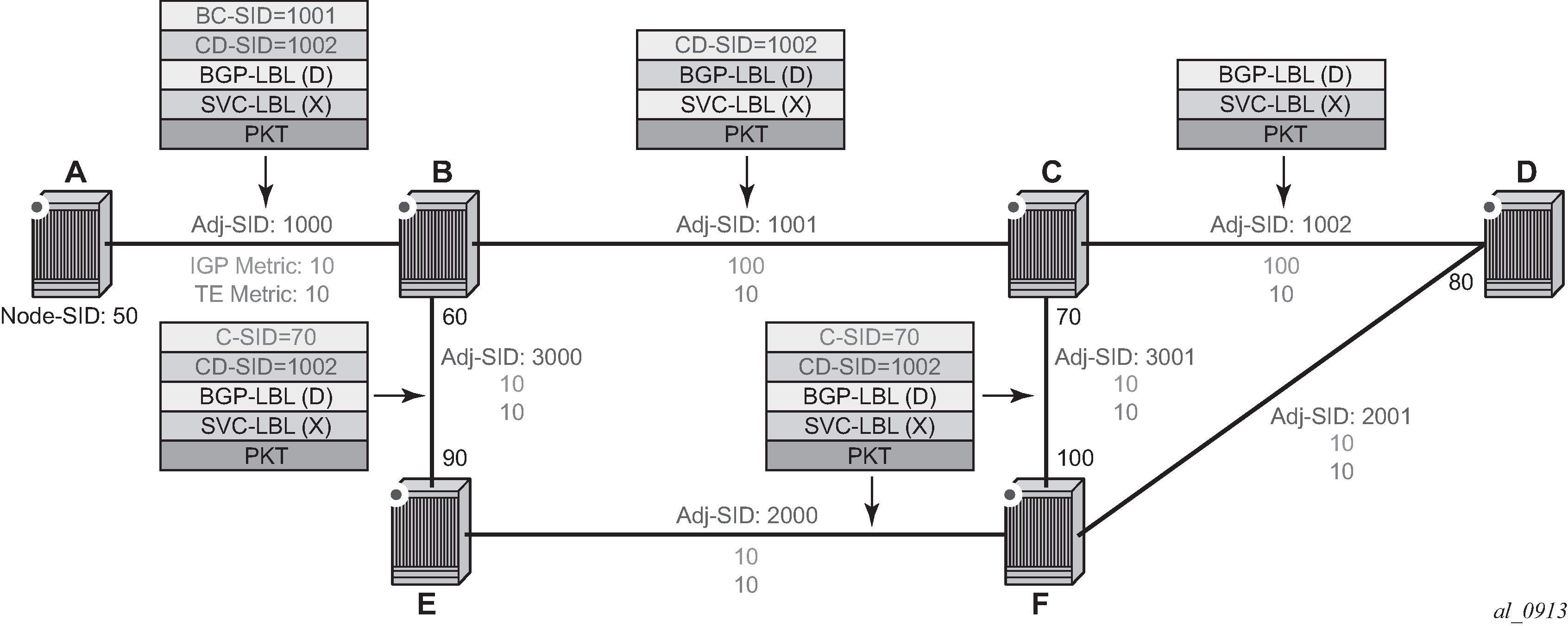
On node A, the user configures an SR-TE LSP to node D with a list of explicit strict hops mapping to the adjacency SID of links: A-B, B-C, and C-D.
Ingress LER A programs a super NHLFE consisting of the label for the adjacency over link C-D and points it to the already-programmed NHLFE of the SR tunnel of its local adjacency over link A-B. The latter NHLFE has the top label and also the outgoing interface to send the packet to.
LSR Node B already programmed the primary NHLFE for the adjacency SID over link C-D and has the ILM with label 1001 point to it. In addition, node B pre-programs the link-protect LFA backup next hop for link B-C and point the same ILM to it.
VPRN service in node A forwards a packet to the VPN-IPv4 prefix X advertised by BGP peer D. SR-TE LSP label stack programming shows the resulting data path at each node for the primary path and for the FRR backup path at LSR B.
SR-TE LSP metric and MTU settings
The MPLS module assigns a TE-LSP the maximum LSP metric value of 16777215 when the local router provides the hop-to-label translation for its path. For a TE-LSP that uses the local CSPF or the PCE for path computation (path-computation-method pce option enabled) by PCE and, or which has its control delegated to PCE (pce-control enabled), the latter returns the computed LSP IGP or TE metric in the PCReq and PCUpd messages. In both cases, the user can override the returned value by configuring an admin metric using the command config>router>mpls>lsp>metric.
-
The MTU setting of a SR-TE LSP is derived from the MTU of the outgoing SR shortest path tunnel it is riding, adjusted with the size of the super NHLFE label stack size.
The following are the details of this calculation:
SR_Tunnel_MTU = MIN {Cfg_SR_MTU, IGP_Tunnel_MTU- (1+frr-overhead)*4}
Where:
-
Cfg_SR_MTU is the MTU configured by the user for all SR tunnels within an IGP instance using config>router>ospf/isis>segment-routing>tunnel-mtu. If no value was configured by the user, the SR tunnel MTU is fully determined by the IGP interface calculation (described below).
-
IGP_Tunnel_MTU is the minimum of the IS-IS or OSPF interface MTU among all the ECMP paths or among the primary and LFA backup paths of this SR tunnel.
-
frr-overhead is set to:
-
value of ti-lfa [max-sr-frr-labels labels] if loopfree-alternates and ti-lfa are enabled in this IGP instance
-
1 if loopfree-alternates and remote-lfa are enabled but ti-lfa is disabled in this IGP instance
-
0 for all other cases
-
This calculation is performed by IGP and passed to the SR module each time it changes because of an updated resolution of the node SID.
SR OS also provides the MTU for adjacency SID tunnel because it is needed in a SR-TE LSP if the first hop in the ERO is an adjacency SID. In that case, this calculation for SR_Tunnel_MTU, initially introduced for a node SID tunnel, is applied to get the MTU of the adjacency SID tunnel.
-
-
The MTU of the SR-TE LSP is derived as follows:
SRTE_LSP_MTU= SR_Tunnel_MTU- numLabels*4
Where:
-
SR_Tunnel_MTU is the MTU SR tunnel shortest path the SR-TE LSP is riding. The formula is as specified above.
-
numLabels is the number of labels found in the super NHLFE of the SR-TE LSP. Note that at LER, the super NHLFE is pointing to the SR tunnel NHLFE, which itself has a primary and a backup NHLFEs.
This calculation is performed by the SR module and is updated each time the SR-TE LSP path changes or the SR tunnel it is riding is updated.
Note: The above calculated SR-TE LSP MTU is used for the determination of an SDP MTU and for checking the Layer 2 service MTU. For the purpose of fragmentation of IP packets forwarded in GRT or in a VPRN over a SR-TE LSP, the data path always deducts the worst case MTU (12 labels) from the outgoing interface MTU for the decision to fragment or not the packet. In this case, the above formula is not used. -
LSR hashing on SR-TE LSPs
The LSR supports hashing up to a maximum of 16 labels in a stack. The LSR is able to hash on the IP headers when the payload below the label stack is IPv4 or IPv6, including when a MAC header precedes it (ethencap-ip option). Alternatively, it is able to hash based only on the labels in the stack, which may include the entropy label (EL) or the hash label. See the 7450 ESS, 7750 SR, 7950 XRS, and VSR MPLS Guide for more information about the hash label and entropy label features.
When the hash-label option is enabled in a service context, a hash label is always inserted at the bottom of the stack as per RFC 6391.
The EL feature, as specified in RFC 6790, indicates the presence of a flow on an LSP that should not be reordered during load balancing. It can be used by an LSR as input to the hash algorithm. The Entropy Label Indicator (ELI) is used to indicate the presence of the EL in the label stack. The ELI, followed by the actual EL, is inserted immediately below the transport label for which the EL feature is enabled. If multiple transport tunnels have the EL feature enabled, the ELI and EL are inserted below the lowest transport label in the stack.
The EL feature is supported with an SR-TE LSP. See the 7450 ESS, 7750 SR, 7950 XRS, and VSR MPLS Guide for more information.
The LSR hashing operates as follows:
If the lbl-only hashing option is enabled, or if one of the other LSR hashing options is enabled but an IPv4 or IPv6 header is not detected below the bottom of the label stack, the LSR parses the label stack and hashes only on the EL or hash label.
If the lbl-ip option is enabled, the LSR parses the label stack and hashes on the EL or hash label and the IP headers.
If the ip-only or eth-encap-ip is enabled, the LSR hashes on the IP headers only.
SR-TE auto-LSP
- SR-TE mesh
- SR-TE one-hop
- SR-TE on demand
The SR-TE mesh LSP feature binds an SR-TE mesh P2P LSP template with one or more prefix lists. When the TE database discovers a router that has an ID matching an entry in the prefix list, it triggers MPLS to instantiate an SR-TE LSP to the router using the LSP parameters in the LSP template.
The SR-TE one-hop LSP feature activates an SR-TE one-hop P2P LSP template. In this case, the TE database tracks each TE link that is made to a directly connected IGP neighbor. It then instructs MPLS to instantiate an SR-TE LSP with the following parameters:
the source address of the local router
an outgoing interface matching the interface index of the TE-link
a destination address matching the router ID of the neighbor on the TE link
In both these types of SR-TE auto-LSPs, the router’s hop-to-label translation or local CSPF computes the label stack required to instantiate the LSP path.
The SR-TE on-demand LSP feature creates an LSP using an SR-TE on-demand P2P LSP template. When an imported BGP route matches an entry in a policy statement with an MPLS create tunnel action, an LSP is created to the next hop for the route. If a route admin tag policy is applied when the route is imported, only an auto-LSP with a template containing a matching admin-tag is created. The SR-TE on-demand LSP supports path computation using hop-to-label translation, local-CSPF, or a PCE.
Feature configuration
This feature uses three SR-TE LSP template types: one-hop P2P, on-demand P2P, and mesh P2P. For the one-hop P2P and mesh P2P types, the configuration of the commands is the same as that of the RSVP-TE auto-LSP.
-
Create an LSP template using one of the following commands, depending on the
type of auto-LSP required.
Classic CLI commands:
- config>router>mpls>lsp-template mesh-p2p-srte
- config>router>mpls>lsp-template one-hop-p2p-srte
- config>router>mpls>lsp-template on-demand-p2p-srte
MD-CLI commands:- configure router mpls lsp-template type p2p-sr-te-mesh
- configure router mpls lsp-template type p2p-sr-te-one-hop
- configure router mpls lsp-template type p2p-sr-te-on-demand
-
In the template configure the common LSP and path level parameters or options
shared by all LSPs using this template.
Note:
These types of LSP templates contain the SR-TE LSP-specific commands and other LSP or path commands that are common to RSVP-TE and SR-TE LSPs, and are supported by the existing RSVP-TE LSP template.
-
Bind the LSP templates as follows:
- For SR-TE mesh P2P LSP template, use the config>router>mpls>lsp-template template-name policy peer-prefix-policy1 [peer-prefix-policy2] command.
- For SR-TE one-hop P2P LSP template, use the config>router>mpls>lsp-template template-name one-hop command.
- For on-demand SR-TE LSP template, the user binds the template to the creation of SR-TE auto-LSPs using the config>router>mpls>auto-lsp template-name command and configures the create-mpls-tunnel command as an action in a route import policy statement.
See Configuring and operating SR-TE for an example configuration of the SR-TE auto-LSP creation using an LSP template of type mesh-p2p-srte.
Automatic creation of an SR-TE mesh LSP
This feature behaves the same way as the RSVP-TE auto-LSP using an LSP template of type mesh-p2p.
The auto-lsp command binds an LSP template of type mesh-p2p-srte with one or more prefix lists. When the TE database discovers a router that has a router ID matching an entry in the prefix list, it triggers MPLS to instantiate an SR-TE LSP to that router using the LSP parameters in the LSP template.
The prefix match can be exact or longest. Prefixes in the prefix list that do not correspond to a router ID of a destination node never match.
The path of the LSP is that of the default path name specified in the LSP template. The hop-to-label translation tool or the local CSPF determines the node SID and adjacency SID corresponding to each loose and strict hop in the default path definition respectively.
The LSP has an auto-generated name using the following structure:
‟TemplateName-DestIpv4Address-TunnelId”
where:
TemplateName = the name of the template
DestIpv4Address = the address of the destination of the auto-created LSP
TunnelId = the TTM tunnel ID
In SR OS, an SR-TE LSP uses three different identifiers:
LSP Index is used for indexing the LSP in the MIB table shared with RSVP-TE LSP. Range:
for provisioned SR-TE LSP, 65536 to 81920
for SR-TE auto-LSP, 81921 to 131070
LSP Tunnel ID is used in the interaction with PCC/PCE. Range is 1 to 65536.
TTM Tunnel ID is the tunnel ID service, shortcut, and steering applications use to bind to the LSP. Range is 655362 to 720897.
The path name is that of the default path specified in the LSP template.
Automatic creation of an SR-TE one-hop LSP
This feature like the RSVP-TE auto-LSP using an LSP template of one-hop-p2p type. Although the provisioning model and CLI syntax differ from that of a mesh LSP by the absence of a prefix list, the actual behavior is quite different. When the one-hop-p2p command is executed, the TE database keeps track of each TE link that comes up to a directly connected IGP neighbor. It then instructs MPLS to instantiate an SR-TE LSP with the following parameters:
the source address of the local router
an outgoing interface matching the interface index of the TE link
a destination address matching the router ID of the neighbor on the TE link
In this case, the hop-to-label translation or the local CSPF returns the SID for the adjacency to the remote address of the neighbor on this link. Therefore, the auto-lsp command binding an LSP template of type one-hop-p2p-srte with the one-hop option results in one SR-TE LSP instantiated to the IGP neighbor for each adjacency over any interface.
Because the local router installs the adjacency SID to a link independent of whether the neighbor is SR-capable, the TE-DB finds the adjacency SID and a one-hop SR-TE LSP can still come up to such a neighbor. However, remote LFA using the neighbor’s node SID does not protect the adjacency SID and so, does also not protect the one-hop SR-TE LSP because the node SID is not advertised by the neighbor.
The LSP has an auto-generated name using the following structure:
‟TemplateName-DestIpv4Address-TunnelId”
where:
TemplateName = the name of the template
DestIpv4Address = the address of the destination of the auto-created LSP
TunnelId = the TTM tunnel ID.
The path name is that of the default path specified in the LSP template.
Automatic creation of an on-demand SR-TE LSP
The SR-TE on-demand LSP simplifies provisioning for networks that may or may not be managed by a network service manager, such as the Nokia NSP. Instead of using a full mesh, LSPs can be automatically created on-demand when a suitable tunnel does not exist for a specific BGP prefix next hop. The prefix could be for VPRN, EVPN, BGP-LU, or BGP shortcut routes. Both intradomain and inter-domain use cases are supported.
- VPRN auto-bind-tunnel
- EVPN VPWS auto-bind-tunnel
- EVPN VPLS auto-bind-tunnel
- BGP-LU, both as an LER and LSR at an ABR or ASBR
- BGP shortcuts
The following figure shows an application of SR-TE on-demand LSPs.
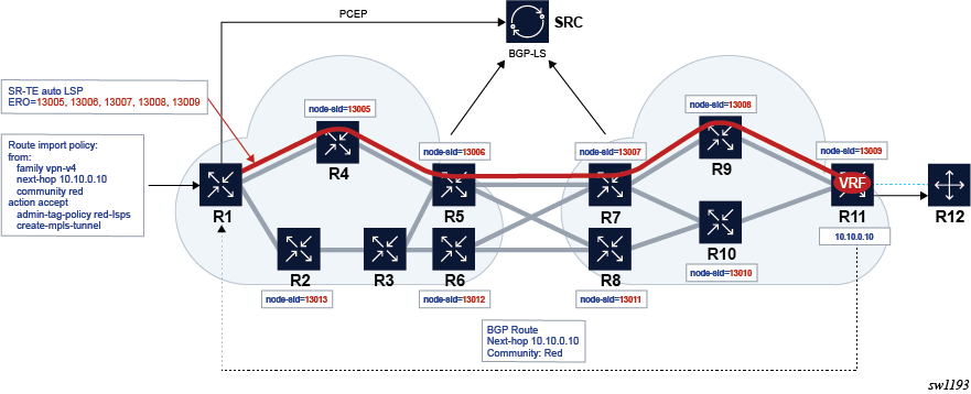
This example combines route transport coloring and auto LSPs to simplify provisioning for intent-based networking for specific services. In this use case, intent means the ability to meet traffic engineering requirements for a service. This could be, for example, a delay or loss, or the ability to steer the service traffic to avoid LSPs that transit specific geographies or prefer those that take another route.
In this example, a BGP route is advertised for a VRF in a PE for a VPRN service. An extended color community is assigned to the route. This color implies an intent associated with the transport requirements.
- The route is matched in a route-import policy.
- An admin-tag policy called red-lsps is applied.
- A trigger action occurs to create an MPLS tunnel to the BGP next-hop for the route.
This causes the head-end router to create an SR-TE auto-LSP that matches the red-lsps admin-tag policy and steers the traffic associated with "red" routes to the far-end PE, into the red LSP. This SR-TE auto-LSP is created based on the configuration in the matching LSP template.
SR OS also offers the ability to use the local CSPF, hop-to-label-translation, or a PCE to provide a path for the red LSP. This is determined by a configuration in the matching LSP template.
Deletion of on-demand SR-TE LSPs
-
The classic CLI no auto-lsp (or MD-CLI delete auto-lsp) command is executed. This triggers MPLS to remove auto-LSPs created by this command.
-
The no create-mpls-tunnel is configured in a policy statement that previously had create-mpls-tunnel configured. This triggers a reevaluation of the policy statement and potentially triggers BGP to inform MPLS that it no longer needs a tunnel.
-
BGP tracks the binding of a route to an admin-tag-policy. If an admin-tag-policy name in a policy statement action changes, the policy is reevaluated, which could change the binding. This may result in a request to create a new tunnel or delete an existing tunnel. However, if the contents of an admin-tag-policy that is referenced in a policy statement action change, BGP does not react (for example, request the creation or deletion of a tunnel), although a subsequent route resolution may change.
-
MPLS reacts to admin-tag changes in the LSP template. When this occurs, it reevaluates the admin-tag-policy associated with a request from BGP and deletes or creates tunnels accordingly.
-
If a new LSP is created that is not an on-demand LSP and is preferred to an existing on-demand LSP, BGP can resolve the next hop over the new LSP and traffic moves to it. In this case, the system does not remove the older less-preferred auto-LSP, which was created through an on-demand LSP trigger, until the next hops are removed.
-
If the LSP template is shut down, all associated LSPs are administratively disabled. To delete the LSP template you must first shut it down, using a no auto-lsp command in classic CLI or delete auto-lsp command in MD-CLI. This removes all the auto-LSPs that are using the template.
Configuring SR-TE on-demand LSPs
Configure SR-TE on-demand LSPs using the steps in this section.
-
Define a policy statement to import the route, as shown in the following
example:
configure>router>policy-options>policy-statement entry from family <family> next-hop <ip-address> community <comm-name> action accept admin-tag-policy <admin-tag-policy-name> create-mpls-tunnel -
Configure the auto-LSP under MPLS with the template type
on-demand-p2p-srte.
The create-mpls-tunnel action is supported for the following address families:
- vpn-ipv4
- vpn-ipv6
- evpn
- label-ipv4
- label-ipv6
- ipv4
- ipv6
The router-policy action assigns an admin-tag-policy to the routes that are imported with a specific next hop and match a specified extended community. In most applications, the extended community is the transport color extended community. The create-mpls-tunnel command action causes BGP to send the next hop and the include and exclude constraints in the admin-tag-policy (if one was assigned to a route by the policy statement) to the MPLS application.
When such a policy statement is applied in the context of a specific VRF, the create-mpls-tunnel command trigger is only actioned by BGP on a per-next-hop basis.
This type of LSP template supports PCE computation, control, and the fallback path computation method if the PCE is unreachable. The auto-LSP is configured using the following command:
configure>router>mpls
     auto-lsp <on-demand-p2p-srte-template-name>
The LSP template may contain an LSP admin-tag-policy. MPLS takes the next hop, and the admin-tag command includes or excludes constraints from BGP and matches them against the auto-LSP statement with a template with an admin-tag command that conforms to the admin-tag-policy constraints.
If BGP does not pass any admin-tag-policy constraints, MPLS only matches against LSP templates that do not have the admin-tag command configured.
If the next-hop and admin-tag-policy match more than one auto-LSP statement, an LSP is created for each matching entry. This results in an ECMP set to the next hop.
Note:Each LSP may have a different admin-tag value, but it is an ECMP next-hop tunnel from the perspective of the colored route that triggers the tunnel creation.
A new SR-TE LSP is consequently created to the next hop passed by BGP according to the parameters contained in the LSP template.
The router tracks the binding between BGP triggers and on-demand LSPs that are successfully created and deleted toward a specified BGP next-hop matching an admin-tag-policy.
Interaction with PCEP
Template-based SR-TE auto-LSPs, with the exception of on-demand SR-TE LSPs, can only be operated as a PCC-controlled LSP. They can, however, be reported to the PCE using the pce-report command. They cannot be operated as a PCE-computed or PCE-controlled LSP. This is the same interaction with PCEP as that of a template-based RSVP-TE LSP.
On-demand SR-TE LSPs can be reported to the PCE and operated as PCE-computed or PCE-controlled LSPs.
The auto LSP can be delegated to a PCE in the configuration of the SR-TE on-demand P2P LSP template, using the pce-control or path-computation-method pce commands.
Fallback to local CSPF or hop-to-label translation is also supported for SR-TE on-demand P2P LSPs in case the PCE becomes unreachable.
In general, an on-demand SR-TE auto-LSP that is PCE controlled or has path computation method PCE is treated as any other PCC-initiated LSP by PCC. Path profile and path group are also supported. Path profile and path group IDs are passed to the PCC in the same way as for a PCC-initiated SR-TE LSP.
Forwarding contexts supported with SR-TE auto-LSP
The following are the forwarding contexts that can be used by an auto-LSP:
resolution of IPv4 BGP label routes and IPv6 BGP label routes (6PE) in TTM
resolution of IPv4 BGP route in TTM (BGP shortcut)
resolution of IPv4 static route to indirect next hop in TTM
VPRN and BGP-EVPN auto-bind for both IPv4 and IPv6 prefixes
The auto-LSP is, however, not available to be used in a provisioned SDP for explicit binding by services. Therefore, an auto-LSP can also not be used directly for auto-binding of a PW template with the use-provisioned-sdp option in BGP-AD VPLS or FEC129 VLL service. However, an auto-binding of a PW template to an LDP LSP, which is then tunneled over an SR-TE auto-LSP is supported.
Allocation and binding of labels to SR-TE LSPs
SR OS supports the allocation and binding of labels to SR-TE LSPs. The LSPs have to be named LSPs or LSPs based on a template, whether the LSPs are PCC initiated (on-demand-p2p-srte template type) or PCE initiated (pce-init-p2p-srte template type).
The result of a binding SID label is the programming of an ILM with a swap operation pointing to the LSP NHLFE.
A single binding SID label can be allocated to a specific LSP.
Named LSPs
configure router mpls lspconfigure router mpls lsp binding-sidconfigure router mpls lsp-bsid-blockA binding SID label can be assigned or removed at any time. In the case where the LSP is delegated to a PCE, the appropriate messages are triggered in both situations (assignment and removal).
The node that allocates the label is considered to be the owner; therefore, the PCE cannot change the binding SID label.
PCC-initiated LSPs
configure router mpls lsp-template binding-sidThe binding SID label is only allocated to LSPs if the template also has pce-report enabled.
The node allocated the label is considered to be the owner; therefore, the PCE cannot change the binding SID label.
PCE-initiated LSPs
There is no command to configure binding SIDs for PCE-initiated LSPs. PCE-initiated LSPs support binding SID labels by default. The PCE initiates the allocation of labels. The only supported mode of operation is for the PCE to request the node to select a label and program it. It is not supported for the PCE to suggest a label value. The node tries to select a label in the dynamic label range and programs it.
The PCE is the initiator of the label allocation and can also request the deallocation of the label.
SR-TE LSP traffic statistics
The collection of traffic statistics on SR-TE LSPs using either a named LSP or SR-TE templates is available on egress of ingress LER. Also, traffic statistics cannot be recorded into an accounting file.
SR-TE LSP statistics are provided without any forwarding class or QoS profile distinction. However, traffic statistics are recorded and made available for each path of the LSP (primary and backup). Statistic indexes are only allocated at the time the path is effectively programmed, are maintained across switchover for primary and standby LSPs only, and are released if egress statistics are disabled or the LSP is deleted.
Rate statistics
SR OS also provides traffic rate statistics. For SR-TE LSPs, including template-based LSPs, the user performs one of the following options to enable that capability:
- configures an accounting policy that uses the combined-mpls-srte-egress record name
- assigns that accounting policy to a specific LSP (or template)
- enables stats collection
The frequency at which the rate is determined is defined using the collection-interval keyword in the accounting policy. The minimum interval is currently 5 minutes.
Rate statistics for SR-TE LSPs cannot be written to an accounting file. The to no-file command must be used in the accounting policy.
Rate statistics are provided in packets per second and Mb/s. Rate statistics are provided as an aggregate across all paths of the LSP that have a statistical index assigned and for all forwarding classes in or out-of-profile.
Rate statistics are only available on egress of the ingress LER. At least two samples are needed to determine a rate.
SR-TE label stack checks
Service and shortcut application SR-TE label stack check
If a packet forwarded in a service or a shortcut application has resulted in the net label stack size being pushed on the packet to exceed the maximum label stack supported by the router, the packet is dropped on the egress. Each service and shortcut application on the router performs a check of the resulting net label stack after pushing all the labels required for forwarding the packet in that context.
To that effect, the MPLS module populates each SR-TE LSP in the TTM with the maximum transport label stack size, which consists of the sum of the values in max-sr-labels label-stack-size and additional-frr-labels labels.
Each service or shortcut application adds the additional, context-specific labels, such as service label, entropy/hash label, and control-word, required to forward the packet in that context and to check that the resulting net label stack size does not exceed the maximum label stack supported by the router.
If the check succeeds, the service is bound or the prefix is resolved to the SR-TE LSP.
If the check fails, the service does not bind to this SR-TE LSP. Instead, it either finds another SR-TE LSP or another tunnel of a different type to bind to, if the user has configured the use of other tunnel types. Otherwise, the service goes down. When the service uses a SDP with one or more SR-TE LSP names, the spoke SDP bound to this SDP remains operationally down as long as at least one SR-TE LSP fails the check. In this case, a new spoke SDP flag is displayed in the show output of the service: "labelStackLimitExceeded". Similarly, the prefix does not get resolved to the SR-TE LSP and is either resolved to another SR-TE LSP or another tunnel type, or becomes unresolved.
The value of additional-frr-labels labels is checked against the maximum value across all IGP instances of the parameter frr-overhead. This parameter is computed within an IGP instance as described in frr-overhead parameter values .
| Condition | frr-overhead parameter value |
|---|---|
segment-routing is disabled in the IGP instance |
0 |
segment-routing is enabled but remote-lfa is disabled |
0 |
segment-routing is enabled and remote-lfa is enabled |
1 |
When the user configures or changes the configuration of additional-frr-labels, MPLS ensures that the new value accommodates the frr-overhead value across all IGP instances.
Example:
The user configures the config>router>isis>loopfree-alternates remote-lfa command.
The user creates a new SR-TE LSP or changes the configuration of an existing as follows: mpls>lsp>max-sr-labels 10 additional-frr-labels 0.
If the check is successful, MPLS adds max-sr-labels and additional-frr-labels and checks that the result is lower or equal to the maximum label stack supported by the router. MPLS then populates the value of {max-sr-labels + additional-frr-labels}, along with tunnel information in TTM, and also passes max-sr-labels to the PCEP module.
Conversely, if the user tries a configuration change that results in a change to the computed frr-overhead, IGP checks that all SR-TE LSPs can properly account for the overhead or the change is rejected. On the IGP, enabling remote-lfa may cause the frr-overhead to change.
Example:
An MPLS LSP is administratively enabled and has mpls>lsp>max-sr-labels 10 additional-frr-overhead 0 configured.
The current configuration in IS-IS has the loopfree-alternates command disabled.
The user attempts to configure
isis>loopfree-alternates remote-lfa. This changes frr-overhead to 1.
This configuration change is blocked.
Control plane handling of egress label stack limitations
As described in Data path support, the egress IOM can push a maximum of 12 labels; however, this number may be reduced if other fields are pushed into the packets. For example, for a VPRN service, the ingress LER can send an IP VPN packet with 12 labels in the stack, including one service label, one label for OAM, and 10 transport labels. However, if entropy is configured, the number of transport labels is reduced by two (Entropy Label (EL) and Entropy Label Indicator (ELI)). Similarly, for EVPN services, the egress IOM may push specific fields that reduce the total number of supported transport labels.
To avoid silent packet drops in cases where the egress IOM cannot push the required number of labels, SR OS implements a set of procedures that prevent the system from sending packets if it is determined that the SR-TE label stack to be pushed exceeds the number of bytes that the egress IOM can put on the wire.
Label stack egress IOM restrictions on FP-based hardware for IPVPN and EVPN services describes the label stack egress IOM restrictions on FP-based hardware for IPVPN and EVPN services.
| Features that reduce the label stack | Source service type | |||||
|---|---|---|---|---|---|---|
| IP-VPN (VPRN) | EVPN-IFL (VPRN) | EVPN VPLS or EVPN Epipe | EVPN B-VPLS (PBB-EVPN) | EVPN-IFF (R-VPLS) | ||
Always Computed3 |
Service Label |
1 |
1 |
1 |
1 |
1 |
OAM Label |
1 |
1 |
0 |
0 |
0 |
|
Control Word |
0 |
0 |
1 |
1 |
1 |
|
ESI Label |
0 |
0 |
1 |
0 |
0 |
|
Computed if configured4 |
Hash Label (mutex with EL) |
1 |
1 |
0 |
0 |
0 |
Entropy EL+ELI |
2 |
2 |
2 |
2 |
2 |
|
|
Required Labels5 |
2 |
2 |
3 |
2 |
2 |
|
Required Labels + Options5 |
4 |
4 |
5 |
4 |
4 |
|
Maximum available labels6 |
12 |
12 |
10 |
6 |
9 |
|
Maximum available transport labels without options7 |
10 |
10 |
7 |
4 |
7 |
|
Maximum available transport labels with options7 |
8 |
8 |
5 |
2 |
5 |
|
The total number of labels configured in the command max-sr-labels label-stack-size [additional-frr-labels labels] must not exceed the labels indicated in the "Maximum available transport labels with/without options" rows in Label stack egress IOM restrictions on FP-based hardware for IPVPN and EVPN services . If the configured LSP labels exceed the available labels in the table, the BGP route next hop for the LSP is not resolved and the system does not even try to send packets to that LSP.
For example, for a VPRN service with EVPN-IFL where the user configures entropy-label, the maximum available transport labels is eight. If an IP Prefix route for next-hop X is received for the service and the SR-TE LSP to-X is the best tunnel to reach X, the system checks that (max-sr-labels + additional-frr-labels) is less than or equal to eight. Otherwise, the IP Prefix route is not resolved.
The same control plane check is performed for other service types, including IP shortcuts, spoke SDPs on IP interfaces, spoke SDPs on Epipes, VPLS, B-VPLS, R-VPLS, and R-VPLS in I-VPLS or PW-SAP. In all cases, the spoke SDP is brought down if the configured (max-sr-labels + additional-frr-labels) is greater than the maximum available transport labels. Maximum available transport labels for IP shortcuts and spoke SDP services indicates the maximum available transport labels for IP shortcuts and spoke SDP services.
| Features that reduce the label stack | Source service type | ||||||||
|---|---|---|---|---|---|---|---|---|---|
| IP shortcuts | Spoke-sdp interface | Spoke-sdp Epipe | Spoke-sdp VPLS | Spoke-sdp B-VPLS | Spoke-sdp R-VPLS | Spoke-sdp R-VPLS I-VPLS | PW-SAP Epipe/interface | ||
Always Computed8 |
Service Label |
0 |
1 |
1 |
1 |
1 |
1 |
1 |
1/1 |
OAM Label |
0 |
1 |
1 |
1 |
1 |
0 |
0 |
0/0 |
|
IPv6 label |
1 |
0 |
0 |
0 |
0 |
0 |
0 |
0/0 |
|
Computed if configured9 |
Hash Label (mutex with EL) |
0 |
1 |
1 |
1 |
1 |
1 |
0 |
0/0 |
Entropy EL+ELI |
2 |
2 |
2 |
2 |
2 |
2 |
2 |
0/0 |
|
Control Word |
0 |
1 |
1 |
1 |
1 |
1 |
1 |
0/0 |
|
Required Labels10 |
1 |
2 |
2 |
2 |
2 |
1 |
1 |
1/1 |
|
Required Labels + Options10 |
3 |
5 |
5 |
5 |
5 |
4 |
4 |
1/1 |
|
Maximum available labels11 |
12 |
9 |
10 |
10 |
6 |
8 |
4 |
10/7 |
|
Maximum available transport labels without options 12 |
11 |
7 |
8 |
8 |
4 |
7 |
3 |
9/7 |
|
Maximum available transport labels with options12 |
9 |
4 |
5 |
5 |
1 |
4 |
0 |
8/6 |
|
In general, the labels shown in Label stack egress IOM restrictions on FP-based hardware for IPVPN and EVPN services and Maximum available transport labels for IP shortcuts and spoke SDP services are valid for network ports that are null or dot1q encapsulated. For QinQ network ports, the available labels are deducted by one.
Flexible SR-TE label stack allocation for services
SR OS supports a dynamic egress label limit configuration mode that extends the number of allowed MPLS labels in the egress label stack by not counting specific labels in the BGP next-hop resolution check when those labels are not used. The configuration mode exists in EVPN services configured on Epipe, VPLS, and VPRN (EVPN-IFL), and in IP-VPN services.
- Classic CLI
+-- dynamic-egress-label-limit no dynamic-egress-label-limit - MD
CLI
+-- dynamic-egress-label-limit <boolean>
When the dynamic-egress-label-limit command is configured, the always-computed labels are no longer considered when resolving the next hop of the route. As a result, the following rules apply to the specified services:
- For VPRN services, the OAM label is never computed. This is true whether the BGP next hop is being resolved over an auto-bind tunnel or an SDP in the vprn>spoke-sdp context. The dynamic mode is supported for EVPN-IFL and IP-VPN families.
- For EVPN (Epipe or VPLS) services with dynamic-egress-label-limit
configured, the control word (CW) and ESI label are only computed if they are used.
- In the case of the CW, the system reduces the egress label limit by one label when the CW is configured in the service. The CW is always accounted when the dynamic-egress-label-limit command is not configured.
- When the dynamic-egress-label-limit command is configured, the ESI label is not accounted for in Epipes or VPLS services without an ES; however, the ESI label is always accounted if dynamic-egress-label-limit is not configured.
When no dynamic-egress-label-limit is configured, the behavior follows the procedures described in Control plane handling of egress label stack limitations.
In summary, when the dynamic-egress-label-limit is configured, the total amount of labels (X) configured in X= (max-sr-labels Y + additional-frr-labels Z) can go higher for EVPN and IP-VPN services.
The following table summarizes the required behavior.
| Features that reduce the Label Stack | no dynamic-egress-label-limit | dynamic-egress-label-limit | |||||
|---|---|---|---|---|---|---|---|
|
IP-VPN (VPRN) |
EVPN-IFL (VPRN) |
EVPN VPLS EVPN Epipe |
IP-VPN (VPRN) |
EVPN-IFL (VPRN) |
EVPN VPLS EVPN Epipe |
||
| Always computed | Service label | 1 | 1 | 1 | 1 | 1 | 1 |
| OAM label 13 | 1 | 1 | 0 | 0 | 0 | 0 | |
| CW | 0 | 0 | 1 | 0 | 0 | 0 | |
| ESI label | 0 | 0 | 1 | 0 | 0 | 0 | |
| Computed if configured | Hash label (mutex with EL) | 1 | 1 | 0 | 1 | 0 | 0 |
| Entropy EL+ELI | 2 | 2 | 2 | 2 | 2 | 2 | |
| CW | 0 | 0 | 0 | 0 | 0 | 1 | |
| ESI label 14 | 0 | 0 | 0 | 0 | 0 | 1 | |
| Required labels | 2 | 2 | 3 | 1 | 1 | 1 | |
| Required labels + All Options | 4 | 4 | 5 | 3 | 3 | 5 | |
| Maximum available labels | 12 | 12 | 10 | 12 | 12 | 10 | |
| Maximum available transport labels without options | 10 | 10 | 7 | 11 | 11 | 9 | |
| Maximum available transport labels with options | 8 | 8 | 5 | 9 | 9 | 5 | |
R-VPLS and B-VPLS services, with EVPN-MPLS enabled, also support the dynamic-egress-label-limit command when dynamic-egress-label-limit is configured, the CW is accounted for only if the control-word command is added.
- In R-VPLS services, the ESI label is not accounted because the routed encapsulation is always larger (and either ESI label for bridged traffic, or routed traffic without ESI label is transmitted by the R-VPLS).
- In B-VPLS services, only the CW applies; there is no ESI label.
IPv6 traffic engineering
This feature extends the traffic engineering capability with the support of IPv6 TE links and nodes.
This feature enhances IS-IS, BGP-LS and the TE database with the additional IPv6 link TLVs and TE link TLVs and provides the following three modes of operation of the IPv4 and IPv6 traffic engineering in a network:
legacy mode
This mode enables the existing traffic engineering behavior for IPv4 RSVP-TE and IPv4 SR-TE. Only the RSVP-TE attributes are advertised in the legacy TE TLVs that are used by both RSVP-TE and SR-TE LSP path computation in the TE domain routers. In addition, IPv6 SR-TE LSP path computation can now use these common attributes.
legacy mode with application indication
This mode is intended for cases where link TE attributes are common to RSVP-TE and SR-TE applications and have the same value, but the user wants to indicate on a per-link basis which application is enabled.
Routers in the TE domain use these attributes to compute path for IPv4 RSVP-TE LSP and IPv4/IPv6 SR-TE LSP.
application specific mode
This mode of operation is intended for use cases where TE attributes may have different values in RSVP-TE and SR-TE applications or are specific to one application (for example, RSVP-TE Unreserved Bandwidth and Max Reservable Bandwidth attributes). This mode is also used to advertise the TE attributes for the SR-TE application when RSVP-TE is disabled on the router.
SR OS does not support configuring TE attributes that are specific to the SR-TE application. As a result, enabling this mode advertises the common TE attributes as sub-TLVs of the new Application Specific Link Attributes TLV. Routers in the TE domain use these attributes to compute paths for IPv4 RSVP-TE LSP and IPv4/IPv6 SR-TE LSP.
See IS-IS IPv4 and IPv6 SR-TE and IPv4 RSVP-TE feature behavior for more details on the IPv4 and IPv6 Traffic Engineering modes of operation.
The feature also adds support of IPv6 destinations to the SR-TE LSP configuration. In addition, this feature also extends the MPLS path configuration with hop indexes that include IPv6 addresses.
IPv6 SR-TE LSP is supported with the hop-to-label and the local CSPF path computation methods. It requires the enabling of the IPv6 traffic engineering feature in IS-IS.
Global configuration
To enable IPv6 TE on the router, the IPv6 TE router ID must have a valid IPv6 address. Use the following CLI command to configure the IPv6 TE router ID:
configure>router>ipv6-te-router-id interface interface-name
The IPv6 TE router ID is a mandatory parameter that uniquely identifies the router as being IPv6 TE capable to other routers in an IGP TE domain. IS-IS advertises this information using the IPv6 TE Router ID TLV as described in TE attributes supported in IGP and BGP-LS.
When the command is not configured or the no form of the command is configured, the value of the IPv6 TE router ID reverts to the preferred primary global unicast address of the system interface. The user can also explicitly enter the name of the system interface to achieve the same outcome.
In addition, the user can specify a different interface and the preferred primary global unicast address of that interface is used instead. Only the system or a loopback interface is allowed because the TE router ID must use the address of a stable interface.
This address must be reachable from other routers in a TE domain and the associated interface must be added to IGP for reachability. Otherwise, IS-IS withdraws the advertisement of the IPv6 TE router ID TLV.
When configuring a new interface name for the IPv6 TE router ID, or when the same interface begins using a new preferred primary global unicast address, IS-IS immediately floods the new value.
If the referenced system is shut down or the referenced loopback interface is deleted or is shut down, or the last IPv6 address on the interface is removed, IS-IS withdraws the advertisement of the IPv6 TE router ID TLV.
IS-IS configuration
To enable the advertisement of additional link IPv6 and TE parameters, a new traffic-engineering-options CLI construct is used.
configure
     router
          ipv6-te-router-id interface interface-name
          no ipv6-te-router-id
          [no] isis [instance]
               traffic-engineering
               no traffic-engineering
               traffic-engineering-options
               no traffic-engineering-options
                    ipv6
                    no ipv6
                    application-link-attributes
                    no application-link-attributes
                         legacy
                         no legacy
The existing traffic-engineering command continues its role as the main command for enabling TE in an IS-IS instance. This command enables the advertisement of the IPv4 and TE link parameters using the legacy TE encoding as per RFC 5305. These parameters are used in IPv4 RSVP-TE and IPv4 SR-TE.
When the ipv6 command under the traffic-engineering-options context is also enabled, then the traffic engineering behavior with IPv6 TE links is enabled. This IS-IS instance automatically advertises the new RFC 6119 IPv6 and TE TLVs and sub-TLVs as described in TE attributes supported in IGP and BGP-LS.
The application-link-attributes context allows the advertisement of the TE attributes of each link on a per-application basis. Two applications are supported in SR OS: RSVP-TE and SR-TE. The legacy mode of advertising TE attributes that is used in RSVP-TE is still supported but can be disabled by using the no legacy command that enables the per-application TE attribute advertisement for RSVP-TE as well.
Additional details of the feature behavior and the interaction of the previously mentioned CLI commands are described in IS-IS IPv4 and IPv6 SR-TE and IPv4 RSVP-TE feature behavior.
MPLS configuration
The SR-TE LSP configuration can accept an IPv6 address in the to and from parameters.
In addition, the MPLS path configuration can accept a hop index with an IPv6 address. The IPv6 address used in the from and to commands in the IPv6 SR-TE LSP, as well as the address used in the hop command of the path used with the IPv6 SR-TE LSP must correspond to the preferred primary global unicast IPv6 address of a network interface or a loopback interface of the corresponding LER or LSR router. The IPv6 address can also be set to the system interface IPv6 address. Failure to follow the preceding IPv6 address guidelines for the from, to, and hop commands causes path computation to fail with failure code ‟noCspfRouteToDestination".
A link-local IPv6 address of a network interface is also not allowed in the hop command of the path used with the IPv6 SR-TE LSP.
All other MPLS-level, LSP-level, and primary or secondary path-level configuration parameters available for an IPv4 SR-TE LSP are supported.
IS-IS, BGP-LS and TE database extensions
IS-IS control plane extensions add support for the following RFC 6119 TLVs in IS-IS advertisements and in TE-DB:
IPv6 interface Address TLV (ISIS_TLV_IPv6_IFACE_ADDR 0xe8)
IPv6 Neighbor Address sub-TLV (ISIS_SUB_TLV_NBR_IPADDR6 0x0d)
IPv6 Global Interface Address TLV (only used by ISIS in IIH PDU)
IPv6 TE Router ID TLV
IPv6 SRLG TLV
IS-IS also supports advertising which protocol is enabled on a TE-link (SR-TE, RSVP-TE, or both) by using the Application Specific Link Attributes (ASLA) sub-TLV as per RFC 8919. This causes the advertising router to send potentially different Link TE attributes for RSVP-TE and SR-TE applications and allows the router receiving the link TE attributes to know which application is enabled on the advertising router. For backward compatibility, the router continues to support the legacy mode of advertising link TE attributes, as recommended in RFC 5305, but the user can disable it.
See IS-IS IPv4 and IPv6 SR-TE and IPv4 RSVP-TE feature behavior for more details of the behavior of the per-application TE capability.
The new TLVs and sub-TLVs are advertised in IS-IS and added into the local TE-DB when received from IS-IS neighbors. In addition, if the database-export command is enabled in this ISIS instance, then this information is also added in the Enhanced TE-DB.
This feature adds the following enhancements to support advertising of the TE parameters in BGP-LS routes over a IPv4 or IPv6 transport:
importing IPv6 TE link TLVs from a local Enhanced TE-DB into the local BGP process for exporting to other BGP peers using the BGP-LS route family that is enabled on an IPv4 or an IPv6 transport BGP session
RFC 6119 IPv6 and TE TLVs and sub-TLVs are carried in BGP-LS link NLRI as per RFC 7752.
When the link TE attributes are advertised by IS-IS on a per-application basis using the ASLA TLV (ISIS TLV Type 16), then they are carried in the new BGP-LS ASLA TLV (TLV Type TBD) as per draft-ietf-idr-bgp-ls-app-specific-attr.
When a TE attribute of a link is advertised for both RSVP-TE and SR-TE applications, there are three methods IS-IS can use. Each method results in a specific way the BGP-LS originator carries this information. These methods are summarized here but more details are provided in IS-IS IPv4 and IPv6 SR-TE and IPv4 RSVP-TE feature behavior.
In legacy mode of operation, all TE attributes are carried in the legacy IS-IS TE TLVs and the corresponding BGP-LS link attributes TLVs as listed in Legacy link TE TLV support in TE-DB and BGP-LS.
In legacy with application indication mode of operation, IGP and BGP-LS advertises the legacy TE attribute TLVs and also advertises the ASLA TLV with the legacy (L) flag set and the RSVP-TE and SR-TE application flags set. No TE sub-sub TLVs are advertised within the ASLA TLV.
The legacy with application indication mode is intended for cases where link TE attributes are common to RSVP-TE and SR-TE applications and have the same value, but the user wants to indicate on a per-link basis which application is enabled.
In application specific mode of operation, the TE attribute TLVs are sent as sub-sub-TLVs within the ASLA TLV. Common attributes to RSVP-TE and SR-TE applications have the main TLV Legacy (L) flag cleared and the RSVP-TE and SR-TE application flags set. Any attribute that is specific to an application (RSVP-TE or SR-TE) is advertised in a separate ASLA TLV with the main TLV Legacy (L) flag cleared and the specific application (RSVP-TE or SR-TE) flags set. This mode is also used to advertise the TE attributes for the SR-TE application when RSVP-TE is disabled on the router.
The application specific mode of operation is intended for cases where TE attributes may have different values in RSVP-TE and SR-TE applications or are specific to one application (for example, the RSVP-TE Unreserved Bandwidth and Max Reservable Bandwidth attributes).
exporting from the local BGP process to the local Enhanced TE-DB of IPv6 and TE link TLVs received from a BGP peer via BGP-LS route family enabled on a IPv4 or IPv6 transport BGP session
support of exporting of IPv6 and TE link TLVs from local Enhanced TE-DB to NSP via the cproto channel on the VSR-NRC
BGP-LS originator node handling of TE attributes
The specification of the BGP-LS originator node in support of the ASLA TLV is written with the following main objectives in mind:
-
Accommodate IGP node advertising the TE attribute in both legacy or application specific modes of operation.
-
Allow BGP-LS consumers (for example, PCE) that support the ASLA TLV to receive per-application attributes, even if the attribute values are duplicated, and easily store them per-application in the TE-DB. Also, if the BGP-LS consumers receive the legacy attributes, they can make a determination without ambiguity that these attributes are only for the RSVP-TE LSP application.
-
Continue supporting older BGP-LS consumers that rely only on the legacy attributes.
The preceding objectives are supported by enhancements implemented in SR OS on the BGP-LS originator node. The following excerpts adapted from draft-ietf-idr-bgp-ls-app-specific-attr describe the enhancements:
Application-specific link attributes received from an IGP node without the use of ASLA encodings continue to be encoded using the respective BGP-LS top-level TLVs.
Application-specific link attributes received from an OSPF node using ASLA sub-TLV or from an IS-IS node using either ASLA sub-TLV or Application-Specific SRLG TLV must be encoded in the BGP-LS ASLA TLV as sub-TLVs. Exceptions to this rule are specified in 3.f and 3.g.
In the case of IS-IS, the following specific procedures are to be followed:
When application-specific link attributes are received from a node with the L-flag set in the IS-IS ASLA sub-TLV and application bits other than RSVP-TE are set in the application bit masks, the application-specific link attributes advertised in the corresponding legacy IS-IS TLVs/sub-TLVs must be encoded within the BGP-LS ASLA TLV as sub-TLVs with the application bits, other than the RSVP-TE bit, copied from the IS-IS ASLA sub-TLV. The link attributes advertised in the legacy IS-IS TLVs/sub-TLVs are also advertised in BGP-LS top-level TLVs as per [RFC7752] [RFC8571] [RFC9104]. The same procedure also applies for the advertisement of the SRLG values from the IS-IS Application-Specific SRLG TLV.
When the IS-IS ASLA sub-TLV has the RSVP-TE application bit set, the link attributes for the corresponding IS-IS ASLA sub-TLVs must be encoded using the respective BGP-LS top-level TLVs as per [RFC7752] [RFC8571] [RFC9104]. Similarly, when the IS-IS Application-Specific SRLG TLV has the RSVP-TE application bit set, the SRLG values within it must be encoded using the top-level BGP-LS SRLG TLV (1096) as per [RFC7752].
The SRLGs advertised in IS-IS Application-Specific SRLG TLVs and the other link attributes advertised in IS-IS ASLA sub-TLVs are required to be collated, on a per-application basis, only for those applications that meet all of the following criteria:
Their bit is set in the SABM/UDABM in one of the two types of IS-IS encodings (for example, IS-IS ASLA sub-TLV).
The other encoding type (for example, IS-IS Application Specific SRLG TLV) has an advertisement with zero-length application bit masks.
There is no corresponding advertisement of that other encoding type (following the example, IS-IS Application Specific SRLG TLV) with that specific application bit set.
For each such application, its collated information must be carried in a BGP-LS ASLA TLV with that application's bit set in the SABM/UDABM.
If the resulting set of collated link attributes and SRLG values is common across multiple applications, they may be advertised in a common BGP-LS ASLA TLV instance, where the bits for all such applications would be set in the application bit mask.
Both the SRLG values from IS-IS Application-Specific SRLG TLVs and the link attributes from IS-IS ASLA sub-TLVs, with the zero-length application bit mask, must be advertised into a BGP-LS ASLA TLV with a zero-length application bit mask, independent of the collation described in 3.c and 3.d.
[RFC8919] allows the advertisement of the Maximum Link Bandwidth within an IS-IS ASLA sub-TLV, even though it is not an application-specific attribute. However, when originating the Maximum Link Bandwidth into BGP-LS, the attribute must be encoded only in the top-level BGP-LS Maximum Link Bandwidth TLV (1089) and must not be advertised within the BGP-LS ASLA TLV.
[RFC8919] also allows the advertisement of the Maximum Reservable Link Bandwidth and the Unreserved Bandwidth within an IS-IS ASLA sub-TLV, even though these attributes are specific to RSVP-TE application. However, when originating the Maximum Reservable Link Bandwidth and Unreserved Bandwidth into BGP-LS, these attributes must be encoded only in the BGP-LS top-level Maximum Reservable Link Bandwidth TLV (1090) and Unreserved Bandwidth TLV (1091) respectively and not within the BGP-LS ASLA TLV.
TE attributes supported in IGP and BGP-LS
Legacy link TE TLV support in TE-DB and BGP-LS lists the TE attributes that are advertised using the legacy link TE TLVs defined in RFC 5305 for IS-IS and in RFC 3630 for OSPF. These TE attributes are carried in BGP-LS in accordance with RFC 7752. These legacy TLVs are already supported in SR OS and in IS-IS, OSPF, and BGP-LS.
To support IPv6 TE, the IS-IS IPv6 TE attributes (IPv6 TE router ID and IPv6 SRLG TLV) are advertised in BGP-LS in accordance with RFC 7752. These attributes can now be advertised within the ASLA TLV in IS-IS as recommended in RFC 8919 and in BGP-LS as recommended in draft-ietf-idr-bgp-ls-app-specific-attr. In the latter case, BGP-LS uses the same TLV type defined in RFC 7752 but is included as a sub-TLV of the new BGP-LS ASLA TLV. The following table also lists the code points for IS-IS and BGP-LS TLVs.
| Link TE TLV description | IS-IS TLV type (RFC 5305) | OSPF TLV type (RFC 3630) | BGP-LS link NLRI link-attribute TLV type (RFC 7752) |
|---|---|---|---|
|
Administrative group (color) |
3 |
9 |
1088 |
|
Maximum link bandwidth |
9 |
6 |
1089 |
|
Maximum reservable link bandwidth |
10 |
7 |
1090 |
|
Unreserved bandwidth |
11 |
8 |
1091 |
|
TE Default Metric |
18 |
5 |
1092 |
|
SRLG |
138 (RFC 4205) |
16 (RFC 4203) |
1096 |
|
IPv6 SRLG TLV |
139 (RFC 6119) |
— |
1096 |
|
IPv6 TE Router ID |
140 (RFC 6119) |
— |
1029 |
|
Application Specific Link Attributes |
16 (RFC 8919) |
— |
1122 (provisional, as per draft-ietf-idr-bgp-ls-app-specific-attr) |
|
Application Specific SRLG TLV |
238 (RFC 8919) |
— |
1122 (provisional, as per draft-ietf-idr-bgp-ls-app-specific-attr) |
The following table lists the TE attributes that are received from a third-party router implementation in legacy TE TLVs, or in the ASLA TLV for the RSVP-TE or SR-TE applications that are added into the local SR OSTE-DB; these are also distributed by the BGP-LS originator. However, these TLVs are not originated by an SR OS router IGP implementation.
| Link TE TLV description | IS-IS TLV type (RFC 7810) | OSPF TLV type (RFC 7471) | BGP-LS link NLRI link-attribute TLV type (RFC 8571) |
|---|---|---|---|
|
Unidirectional Link Delay |
33 |
27 |
1114 |
|
Min/Max Unidirectional Link Delay |
34 |
28 |
1115 |
|
Unidirectional Delay Variation |
35 |
29 |
1116 |
|
Unidirectional Link Loss |
36 |
30 |
1117 |
|
Unidirectional Residual Bandwidth |
37 |
31 |
1118 |
|
Unidirectional Available Bandwidth |
38 |
32 |
1119 |
|
Unidirectional Utilized Bandwidth |
39 |
33 |
1120 |
Any other TE attribute received in a legacy TE TLV or in an Application Specific Link Attributes TLV is not added to the local router TE-DB and, therefore, is not distributed by the BGP-LS originator.
IS-IS IPv4 and IPv6 SR-TE and IPv4 RSVP-TE feature behavior
The TE feature in IS-IS allows the advertising router to indicate to other routers in the TE domain which applications the advertising router has enabled: RSVP-TE, SR-TE, or both. As a result, a receiving router can safely prune links that are not enabled in one of the applications from the topology when computing a CSPF path in that application.
TE behavior consists of the following steps:
A valid IPv6 address value must exist for the system or loopback interface assigned to the ipv6-te-router-id command. The IPv6 address value can be either the preferred primary global unicast address of the system interface (default value) or that of a loopback interface (user configured).
The IPv6 TE router ID is mandatory for enabling IPv6 TE and enabling the router to be uniquely identified by other routers in an IGP TE domain as being IPv6 TE capable. If a valid value does not exist, the IPv6 and TE TLVs described in IS-IS, BGP-LS and TE database extensions are not advertised.
The traffic-engineering command enables the existing traffic engineering behavior for IPv4 RSVP-TE and IPv4 SR-TE. Enable the rsvp context on the router and enable rsvp on the interfaces to have IS-IS begin advertising TE attributes in the legacy TLVs. By default, the rsvp context is enabled as soon as the mpls context is enabled on the interface. If ipv6 knob is also enabled, the RFC 6119 IPv6 and TE link TLVs described in the preceding bullet are advertised such that a router receiving these advertisements can compute paths for IPv6 SR-TE LSP in addition to paths for IPv4 RSVP-TE LSPs and IPv4 SR-TE LSPs. The receiving node cannot determine if truly IPv4 RSVP-TE, IPv4 SR-TE, or IPv6 SR-TE applications are enabled on the other routers. Legacy TE routers must assume that RSVP-TE is enabled on those remote TE links it received advertisements for.
When the ipv6 command is enabled, IS-IS automatically begins advertising the RFC 6119 TLVs and sub-TLVs: IPv6 TE Router ID TLV, IPv6 Interface Address sub-TLV, and IPv6 Neighbor Address sub-TLV, or Link-Local Interface Identifiers sub-TLV if the interface has no global unicast IPv6 address. The TLVs and sub-TLVs are advertised regardless of whether TE attributes are added to the interface in the mpls context. The advertisement of these TLVs is only performed when the ipv6 knob is enabled and ipv6-routing is enabled in this IS-IS instance and ipv6-te-router-id has a valid IPv6 address.
A network IP interface is advertised with the Link-Local Interface identifiers sub-TLV if the network IP interface meets the following conditions:
Network IP interface has a link-local IPv6 address and no global unicast IPv6 address on the interface ipv6 context.
Network IP interface has no IPv4 address and may or may not have the unnumbered option enabled on the interface ipv4 context.
The application-link-attributes command enables the ability to send the link TE attributes on a per-application basis and explicitly conveys that RSVP-TE or SR-TE is enabled on that link on the advertising router.
Three modes of operation that are allowed by the application-link-attributes command.
-
legacy mode
For legacy mode, use the no application-link-attributes command.
The application-link-attributes command is disabled by default and the no form matches the behavior described in list item 2. It enables the existing traffic engineering behavior for IPv4 RSVP-TE and IPv4 SR-TE. Only the RSVP-TE attributes are advertised in the legacy TE TLVs that are used by both RSVP-TE and SR-TE LSP CSPF in the TE domain routers. No separate SR-TE attributes are advertised.
If the ipv6 command is also enabled, the RFC 6119 IPv6 and TE link TLVs are advertised in the legacy TLVs. A router in the TE domain receiving these advertisements can compute paths for IPv6 SR-TE LSPs.
If the user shuts down the rsvp context on the router or on a specific interface, the legacy TE attributes of all the MPLS interfaces or of that specific MPLS interface are not advertised. Routers can still compute SR-TE LSPs using those links but LSP path TE constraints are not enforced because the links appear in the TE Database as if they did not have TE parameters.
Legacy link TE TLV support in TE-DB and BGP-LS shows the encoding of the legacy TE TLVs in both IS-IS and BGP-LS.
-
legacy mode with application indication
To use legacy mode with application indication, enable the legacy command in the configure router isis traffic-engineering-options application-link-attributes context.
The legacy with application indication mode is intended for cases where link TE attributes are common to RSVP-TE and SR-TE applications and have the same value, but the user wants to indicate on a per-link basis which application is enabled.
IS-IS continues to advertise the legacy TE attributes for both RSVP-TE and SR-TE applications and includes the new Application Specific Link Attributes TLV with the application flag set to RSVP-TE or SR-TE but without the sub-sub-TLVs. IS-IS also advertises the Application Specific SRLG TLV with the application flag set to RSVP-TE or SR-TE but without the actual values of the SRLGs.
Routers in the TE domain use these attributes to compute CSPF for IPv4 RSVP-TE LSP and IPv4 SR-TE LSP.
If the ipv6 command is also enabled, the RFC 6119 IPv6 and TE TLVs are advertised. A router in the TE domain that receives these advertisements can compute paths for IPv6 SR-TE LSP.
Note: The segment-routing command must be enabled in the IS-IS instance or the flag for the SR-TE application is not set in the Application Specific Link Attributes TLV or in the Application Specific SRLG TLV.To disable advertising of RSVP-TE attributes, shut down the rsvp context on the router.
Note: Doing this reverts to advertising the link SR-TE attributes using the Application Specific Link Attributes TLV and the TE sub-sub-TLVs as shown in Details of link TE advertisement methods. If legacy attributes were used, legacy routers wrongly interpret that this router enabled RSVP and may signal RSVP-TE LSPs using its links.Legacy link TE TLV support in TE-DB and BGP-LS lists the code points for IS-IS and BGP-LS legacy TLVs.
The following excerpt from the Link State Database (LSDB) shows the advertisement of TE parameters for a link with both RSVP-TE and SR-TE applications enabled.
-
-
application specific mode
To use legacy mode with application indication, disable the legacy command in the configure router isis traffic-engineering-options application-link-attributes context.
The application specific mode of operation is intended for use cases where TE attributes may have different values in RSVP-TE and SR-TE applications (this capability is not supported in SR OS) or are specific to one application (for example, RSVP-TE Unreserved Bandwidth and Max Reservable Bandwidth attributes).
IS-IS advertises the TE attributes that are common to RSVP-TE and SR-TE applications in the sub-sub-TLVs of the new ASLA sub-TLV. IS-IS also advertises the link SRLG values in the Application Specific SRLG TLV. In both cases, the application flags for RSVP-TE and SR-TE are also set in the sub-TLV.
IS-IS begins to advertise the TE attributes that are specific to the RSVP-TE application separately in the sub-sub-TLVs of the new application attribute sub-TLV. The application flag for RSVP-TE is also set in the sub-TLV.
SR OS does not support configuring and advertising TE attributes that are specific to the SR-TE application.
Common value RSVP-TE and SR-TE TE attributes are combined in the same application attribute sub-TLV with both application flags set, while the non-common value TE attributes are sent in their own application attribute sub-TLV with the corresponding application flag set.
Attribute mapping per application shows an excerpt from the Link State Database (LSDB). Attributes in green font are common to both RSVP-TE and SR-TE applications and are combined, while the attribute in red font is specific to RSVP-TE application and is sent separately.
Figure 25. Attribute mapping per application 
Routers in the TE domain use these attributes to compute CSPF for IPv4 SR-TE LSP and IPv4 SR-TE LSPs. If the ipv6 command is also enabled, the RFC 6119 IPv6 TLVs are advertised. A router in the TE domain receiving these advertisements can compute paths for IPv6 SR-TE LSP.
Note: The segment-routing command must be enabled in the IS-IS instance or the common TE attribute is not advertised for the SR-TE application.To disable advertising of RSVP-TE attributes, shut down the rsvp context on the router.
Details of link TE advertisement methods summarizes the IS-IS link TE parameter advertisement details for the three modes of operation of the IS-IS advertisement.
Table 13. Details of link TE advertisement methods IGP traffic engineering options Link TE advertisement details RSVP-TE (rsvp enabled on interface)
SR-TE (segment-routing enabled in IGP instance)
RSVP-TE and SR-TE (rsvp enabled on interface and segment-routing enabled in IGP instance)
Legacy mode:
Use the no application-link-attributes command.
Legacy TE TLVs
—
Legacy TE TLVs
Legacy mode with application indication:
Enable configure router isis traffic-engineering-options application-link-attributes legacy
rsvp disabled on router
(rsvp operationally down on all interfaces)
—
Legacy TE TLVs
ASLA TLV -Flags: {Legacy=0, SR-TE=1}; TE sub-sub-TLVs
Legacy TE TLVs
ASLA TLV -Flags: {Legacy=1, RSVP-TE=0, SR-TE=1}
rsvp enabled on router
Legacy TE TLVs
ASLA TLV -Flags: {Legacy=1, RSVP-TE=1}
Legacy TE TLVs
ASLA TLV -Flags: {Legacy=1, SR-TE=1}
Legacy TE TLVs
ASLA TLV -Flags: {Legacy=1, RSVP-TE=1, SR-TE=1}
Application specific mode:
Disable configure router isis traffic-engineering-options application-link-attributes legacy
ASLA TLV -Flags: {Legacy=0, RSVP-TE=1}; TE sub-sub-TLVs
ASLA TLV -Flags: {Legacy=0, SR-TE=1}; TE sub-sub-TLVs
ASLA TLV -Flags: {Legacy=0, RSVP-TE=1; SR-TE=1}; TE sub-sub-TLVs (common attributes)
ASLA TLV -Flags:
{Legacy=0, RSVP-TE=1}; TE sub-sub-TLVs (RSVP-TE specific attributes; for example, Unreserved BW and Resvble BW)
ASLA TLV -Flags:
{Legacy=0, SR-TE=1}; TE sub-sub-TLVs (SR-TE specific attributes; not supported in SR OS 19.10.R1)
-
IPv6 SR-TE LSP support in MPLS
This feature is supported with the hop-to-label, the local CSPF, and the PCE (PCC-initiated and PCE-initiated) path computation methods.
All capabilities of an IPv4 provisioned SR-TE LSP are supported with an IPv6 SR-TE LSP unless indicated otherwise. This section describes some important differences between an IPv4 and IPv6 SR-TE LSP support in MPLS.
The IPv6 address used in the from and to commands in the IPv6 SR-TE LSP, as well as the address used in the hop command of the path used with the IPv6 SR-TE LSP, must correspond to the preferred primary global unicast IPv6 address of a network interface or a loopback interface of the corresponding LER or LSR router. The IPv6 address can also be set to the system interface IPv6 address. Failure to follow the preceding IPv6 address guidelines for the from, to, and hop commands causes path computation to fail with failure code ‟noCspfRouteToDestination". A link-local IPv6 address of a network interface is also not allowed in the hop command of the path used with the IPv6 SR-TE LSP. The configuration fails.
A TE link with no global unicast IPv6 address and only a link local IPv6 address can be used in the path computation by the local CSPF. The address shown in the Computed Hops and in the Actual Hops fields of the output of the path show command uses the neighbor’s IPv6 TE router ID and the Link-Local Interface Identifiers sub-TLV. The exceptions are if the interface is of type broadcast or type point-to-point but also has a local IPv4 address. Only the neighbor’s IPv6 TE router ID is shown, as the Link-Local Interface Identifiers sub-TLV is not advertised in these situations.
The UP value of the global MPLS IPv4 state requires that the system interface be in the admin UP state and to have a valid IPv4 address.
The UP value of the global MPLS IPv6 state requires that the interface used for the IPv6 TE router ID be in admin UP state and to have a valid preferred primary IPv6 global unicast address.
The UP value of the TE interface MPLS IPv4 state requires the interface be in the admin UP state in the router context and the global MPLS IPv4 state be in UP state.
The UP value of the TE interface MPLS IPv6 state requires the interface be in the admin UP state in the router context and the global MPLS IPv6 state be in UP state.
IPv6 SR-TE auto-LSP
This feature supports the auto-creation of an IPv6 SR-TE mesh LSP and for an IPv6 SR-TE one-hop LSP.
The SR-TE mesh LSP feature specifically binds an LSP template of type mesh-p2p-srte with one or more IPv6 prefix lists. When the TE-DB discovers a router that has an IPv6 TE router ID matching an entry in the prefix list, it triggers MPLS to instantiate an SR-TE LSP to that router using the LSP parameters in the LSP template.
The SR-TE one-hop LSP feature specifically activates an LSP template of type one-hop-p2p-srte. In this case, the TE database keeps track of each TE link that comes up to a directly connected IGP TE neighbor. It then instructs MPLS to instantiate an SR-TE LSP with the following parameters:
-
the source IPv6 address of the local router
-
an outgoing interface matching the interface index of the TE-link
-
a destination address matching the IPv6 TE router ID of the neighbor on the TE link
A family CLI leaf is added to the LSP template configuration and must be set to the ipv6 value. By default, this command is set to the ipv4 value for backward compatibility. When establishing both IPv4 and IPv6 SR-TE mesh auto-LSPs with the same parameters and constraints, a separate LSP template of type mesh-p2p-srte must be configured for each address family with the family command set to the IPv4 or IPv6 value. SR-TE one-hop auto-LSPs can only be established for either IPv4 or IPv6 family, not both. The family command in the LSP template of type one-hop-p2p-srte should be set to the needed IP family value.
An IPv6 SR-TE auto-LSP can be reported to a PCE but cannot be delegated or have its paths computed by the PCE.
All capabilities of an IPv4 SR-TE auto-LSP are supported with an IPv6 SR-TE auto-LSP unless indicated otherwise.
OSPF link TE attribute reuse
This section describes the support of OSPF application specific TE link attributes.
OSPF application specific TE link attributes
Existing OSPFv2 TE-related link attribute advertisement (for example, bandwidth) definitions are used in RSVP-TE deployments (see draft-ietf-spring-segment-routing-policy-07.txt for more information). In the beginning only the RSVP-TE was using these TE-related link attributes, however additional applications (for example, Segment Routing Traffic Engineering (SR-TE)) emerged and require link attributes. The link attributes for these new applications may not always be identical as those advertised for RSVP-TE.
This usage has introduced ambiguity in deployments that include a mix of RSVP-TE and SR-TE support. For example, it is not possible to unambiguously indicate the specific advertisements used by RSVP-TE and SR-TE. Although this may not be an issue for fully congruent topologies, any incongruence causes ambiguity. An additional issue arises in cases where both applications are supported on a link but the link attribute values associated with each application differ. Advertisements without OSPFv2 application specific TE link attributes do not support the advertisement of application specific values for the same attribute on a specific link.
CLI syntax:
Config
   router
      ospf
         traffic-engineering-options
               sr-te {legacy|application-specific-link-attributes}
               no sr-te
The traffic-engineering-options command enables the context to configure advertisement of the TE attributes of each link on a per-application basis. Two applications are supported in SR OS: RSVP-TE and SR-TE.
The legacy mode of advertising TE attributes that is used in RSVP-TE is still supported. In addition, the following configuration options are allowed:
- no sr-te
- advertises the TE information for RSVP links using TE Opaque LSAs. The no form is the default value.
- sr-te legacy
- advertises the TE information for MPLS-enabled SR links using TE Opaque LSAs
- sr-te application-specific-link-attributes
- advertises the TE information for MPLS-enabled SR links using the new Application Specific Link Attributes (ASLA) TLVs
The RFC 8920 defines a subset of all possible TE extensions and TE Metric Extensions that can be encoded within Application Specific Link sub TLVs. Nokia support for ASLA extended link TLV encoding describes the relevant values for SR OS.
| OSPFv2 extended link TLV sub-TLVs (RFC7684) | ||||
|---|---|---|---|---|
IANA |
Attribute Type |
TE-DB15 |
SR OS sub-TLV of Extended Link TLV16 |
SR OS Nested sub-TLV of ASLA Extended Link TLV encoding17 |
10 |
ASLA |
✓ |
✓ |
— |
11 |
Shared Risk Link Group |
✓ |
— |
✓ |
12 |
Unidirectional Link Delay |
✓ |
— |
— |
13 |
Min/Max Unidirectional Link Delay |
✓ |
— |
— |
14 |
Unidirectional Delay Variation |
✓ |
— |
— |
15 |
Unidirectional Link Loss |
✓ |
— |
— |
16 |
Unidirectional Residual Bandwidth |
✓ |
— |
— |
17 |
Unidirectional Available Bandwidth |
✓ |
— |
— |
18 |
Unidirectional Utilized Bandwidth |
✓ |
— |
— |
19 |
Administrative Group |
✓ |
— |
Y |
20 |
Extended Administrative Group |
✓ |
— |
— |
22 |
TE Metric |
✓ |
— |
✓ |
23 |
Maximum Link Bandwidth |
✓ |
✓ |
— |
The solution proposed in the OSPF Link Traffic Engineering Attribute Reuse Draft (draft-ietf-ospf-te-link-attr-reuse-14.txt) assumes that OSPF does not need to move all RSVP-TE attributes from the TE Opaque LSA into the Extended Link LSA. For, RSVP-TE, consequently, there is no significant modification and it can continue to be advertised using existing OSPF TLVs. For SR-TE and future applications, the ASLA TLVs may be used. Alternatively, existing TE Opaque LSAs could be used through configuration. Configuration considerations for TE opaque LSAs describes the possible configurations for TE Opaque LSAs.
| Interior gateway protocol configuration | ospf>traffic-engineering <20.7 | ospf>traffic-engineering ospf>te-opts>no sr-te |
ospf>traffic-engineering ospf>te-opts>sr-te legacy |
ospf>traffic-engineering ospf>te-opts>sr-te application-link-attribute |
|---|---|---|---|---|
Interface config |
— |
— |
— |
— |
MPLS + RSVP |
TE-Opaque |
TE-Opaque |
TE-Opaque |
TE-Opaque |
MPLS + SR |
— |
— |
TE-Opaque18 |
ASLA (SR-TE) |
MPLS + RSVP + SR |
TE-Opaque |
TE-Opaque |
TE-Opaque |
TE-Opaque (RSVP) + ASLA (SRTE) |
Configuring and operating SR-TE
This section provides information about the configuration and operation of the SR-TE LSP.
SR-TE configuration prerequisites
To configure SR-TE, the user must first configure prerequisite parameters.
-
Configure the label space partition for the Segment Routing Global Block (SRGB)
for all participating routers in the segment routing domain by using the
mpls-labels>sr-labels
command.
mpls-labels — sr-labels start 200000 end 200400 — exit -
Enable segment routing, traffic engineering, and advertisement of router
capability in all participating IGP instances in all participating routers by
using the traffic-engineering,
advertise-router-capability, and
segment-routing commands.
ospf 0 — traffic-engineering — advertise-router-capability area — loopfree-alternates remote-lfa — area 0.0.0.202 — stub — no summaries — exit — interface "system" — node-sid index 194 — no shutdown — exit — interface "toSim199" — interface-type point-to-point — no shutdown — exit — interface "toSim213" — interface-type point-to-point — no shutdown — exit — interface "toSim219" — interface-type point-to-point — metric 2000 — no shutdown — exit — exit — segment-routing — prefix-sid-range global — no shutdown — exit — no shutdown — exit -
Configure an segment routing tunnel MTU for the IGP instance, if required, by
using the tunnel-mtu command.
prefix-sid-range global — tunnel-mtu 1500 — no shutdown -
Assign a node SID to each loopback interface that a router would use as the
destination of a segment routing tunnel by using the node-sid
command.
ospf 0
        — area 0.0.0.202
            — interface "system"
                — node-sid index 194
                — no shutdown
            — exit
SR-TE LSP configuration overview
The use can configure an SR-TE LSP as a label switched path (LSP) under the MPLS context by specifying the sr-te LSP type.
config>router>mpls>lsp lsp-name [mpls-tp src-tunnel-num | sr-te]
The user can configure a primary path for an RSVP LSP.
Use the following CLI syntax to associate an empty path or a path with strict or loose explicit hops with the primary paths of the SR-TE LSP:
config>router>mpls>path>hop hop-index ip-address {strict | loose}
    — config>router>mpls>lsp>primary path-name
Configuring path computation and control for SR-TE LSPs
Use the following syntax to configure the path computation requests only (PCE-computed) or both path computation requests and path updates (PCE-controlled) to the PCE for a specific LSP:
config>router>mpls>lsp>path-computation-method pce
    — config>router>mpls>lsp>pce-control
Use the following command syntax to ensure the PCC LSP database is synchronized with the PCE LSP database using the PCEP PCRpt (PCE Report) message for LSPs that have the following commands enabled:
config>router>mpls>pce-report sr-te {enable | disable}
    — config>router>mpls>lsp>pce-report {enable | disable | inherit}
Configuring path profile and group for PCC-initiated and PCE-computed/controlled LSP
The PCE supports the computation of disjoint paths for two different LSPs originating or terminating on the same or different PE routers. To indicate this constraint to PCE, the user must configure the PCE path profile ID and path group ID the LSP belongs to. These parameters are passed transparently by PCC to PCE and are therefore opaque data to the router. Use the following syntax to configure the path profile and path group:
config>router>mpls>lsp>path-profile profile-id [path-group group-id]
The association of the optional path group ID is to allow PCE determine which profile ID this path group ID must be used with. One path group ID is allowed per profile ID. The user can, however, enter the same path group ID with multiple profile IDs by executing this command multiple times. A maximum of five entries of path-profile [path-group] can be associated with the same LSP. More details of the operation of the PCE path profile are provided in the PCEP section of this guide.
Configuring SR-TE LSP label stack size
Use the following syntax to configure the maximum number of labels which the ingress LER can push for a specific SR-TE LSP:
config>router>mpls>lsp>max-sr-labels label-stack-size
This command allows the user to reduce the SR-TE LSP label stack size by accounting for additional transport, service, and other labels when packets are forwarded in a specific context. See Data path support for more information about label stack size requirements in various forwarding contexts. If the CSPF on the PCE or the router's hop-to-label translation could not find a path that meets the maximum SR label stack, the SR-TE LSP remains on its current path or remains down if it has no path. The range is 1-10 labels with a default value of 6.
Configuring adjacency SID parameters
Configure the adjacency hold timer for the LFA or remote LFA backup next hop of an adjacency SID.
Use the following CLI command syntax to configure the length of the interval during which LTN or ILM records of an adjacency SID are kept:
config>router>ospf>segment-routing>adj-sid-hold seconds[1..300, default 15]
    — config>router>isis>segment-routing>adj-sid-hold seconds[1..300, default 15]
adj-sid-hold 15
    — no entropy-label-capability
    — prefix-sid-range global
    — no tunnel-table-pref
    — no tunnel-mtu
    — no backup-node-sid
    — no shutdown
When protection is enabled globally for all node SIDs and local adjacency SIDs with the loopfree-alternates command in IS-IS or OSPF at the LER and LSR, applications may exist for which the user wants traffic to never divert from the strict hop computed by CSPF for an SR-TE LSP. In such cases, use the following CLI command syntax to disable protection for all adjacency SIDs formed over a network IP interface:
config>router>ospf>area>if>no sid-protection
    — config>router>isis>if>no sid-protection
Configuration output
node-sid index 194
    — no sid-protection
    — no shutdown
Configuring PCC-controlled, PCE-computed, and PCE-controlled SR-TE LSPs
The following example shows the configuration output of PCEP PCC parameters on LER routers that require peering with the PCE server:
keepalive 30
    — dead-timer 120
    — no local-address
    — unknown-message-rate 10
    — report-path-constraints
    — peer 192.168.48.226
        — no shutdown
    — exit
    — no shutdown
The following example shows the configuration of a PCC-controlled SR-TE LSP that is not reported to the PCE:
lsp "to-SanFrancisco" sr-te
        — to 192.168.48.211
        — path-computation-method local-cspf
        — pce-report disable
        — metric 10
        — primary "loose-anycast"
        — exit
        — no shutdown
    — exit
The following example shows the configuration of a PCC-controlled SR-TE LSP that is reported to the PCE:
lsp "to-SanFrancisco" sr-te
        — to 192.168.48.211
        — path-computation-method local-cspf
        — pce-report enable
        — metric 10
        — primary "loose-anycast"
        — exit
        — no shutdown
    — exit
The following example shows the configuration of a PCE-computed SR-TE LSP that is reported to the PCE:
lsp "to-SanFrancisco" sr-te
        — to 192.168.48.211
        — path-computation-method local-cspf
        — pce-report enable
        — metric 10
        — primary "loose-anycast"
        — exit
        — no shutdown
    — exit
The following example shows the configuration of a PCE-controlled SR-TE LSP with no PCE path profile:
lsp "from Reno to Atlanta no Profile" sr-te
        — to 192.168.48.224
        — path-computation-method local-cspf
        — pce-report enable
        — pce-control
        — primary "empty"
        — exit
        — no shutdown
    — exit
The following example shows the configuration of a PCE-controlled SR-TE LSP with a PCE path profile and a maximum label stack set to a non-default value:
lsp "from Reno to Atlanta no Profile" sr-te
        — to 192.168.48.224
        — max-sr-labels 8 additional-frr-labels 1
        — path-computation-method pce
        — pce-report enable
        — pce-control
        — path-profile 10 path-group 2
        — primary "empty"
            — bandwidth 15
        — exit
        — no shutdown
    — exit
Configuring a mesh of SR-TE auto-LSPs
The following shows the detailed configuration for the creation of a mesh of SR-TE auto-LSPs. The network uses IS-IS with the backbone area being in Level 2 and the leaf areas being in Level 1.
The NSP is used for network discovery only and the NRC-P learns the network topology using BGP-LS.
Multi-level IS-IS topology in the NSP GUI shows the view of the multi-level IS-IS topology in the NSP GUI. The backbone L2 area is highlighted in green.
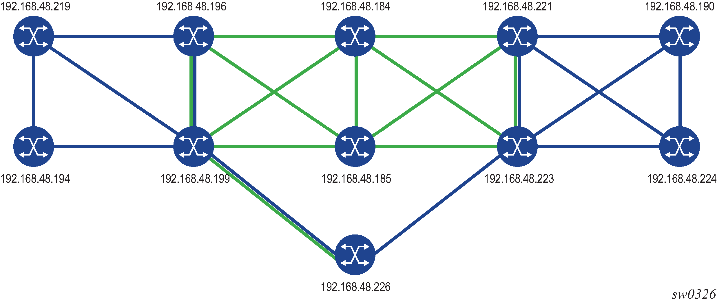
The mesh of SR-TE auto-LSPs is created in the backbone area and originates on an ABR node with address 192.168.48.199 (Phoenix 199). The LSP template uses a default path that includes an anycast SID prefix corresponding to a transit routers 192.168.48.184 (Dallas 184) and 192.168.48.185 (Houston 185).
The following is the configuration of transit router Dallas 184, which shows the creation of a loopback interface with the anycast prefix and the assignment of a SID to it. The same configuration must be performed on the transit router Houston 185. See lines marked with an asterisk (*).
*A:Dallas 184>config>router# info
---------------------------------------------------
echo "IP Configuration"
#--------------------------------------------------
        if-attribute
            admin-group "olive" value 20
            admin-group "top" value 10
            srlg-group "top" value 10
        exit
        interface "anycast-sid"                                                    *
            address 192.168.48.99/32                                               *
            loopback                                                               *
            no shutdown                                                            *
        exit
        interface "system"
            address 192.168.48.184/32
            no shutdown
        exit
        interface "toJun164"
            address 10.19.2.184/24
            port 1/1/4:10
            no shutdown
        exit
        interface "toSim185"
            address 10.0.3.184/24
            port 1/1/2
            no shutdown
        exit
        interface "toSim198"
            address 10.0.2.184/24
            port 1/1/3
            if-attribute
                admin-group "olive"
            exit
            no shutdown
        exit
        interface "toSim199"
            address 10.0.13.184/24
            port 1/1/5
            no shutdown
        exit
        interface "toSim221"
            address 10.0.4.184/24
            port 1/1/1
            no shutdown
        exit
        interface "toSim223"
            address 10.0.14.184/24
            port 1/1/6
            no shutdown
        exit
#--------------------------------------------------

*A:Dallas 184>config>router>isis# info
----------------------------------------------
            level-capability level-2
            area-id 49.0000
            database-export identifier 10 bgp-ls-identifier 10
            traffic-engineering
            advertise-router-capability area
            level 2
                wide-metrics-only
            exit
            interface "system"
                ipv4-node-sid index 384
                no shutdown
            exit
            interface "toSim198"
                interface-type point-to-point
                no shutdown
            exit
            interface "toSim185"
                interface-type point-to-point
                no shutdown
            exit
            interface "toSim221"
                interface-type point-to-point
                no shutdown
            exit
            interface "toSim199"
                interface-type point-to-point
                level 2
                    metric 100
                exit
                no shutdown
            exit
            interface "toSim223"
                interface-type point-to-point
                level 2
                    metric 100
                exit
                no shutdown
            exit
            interface "anycast-sid"                                                *
                ipv4-node-sid index 99                                             *
                no shutdown                                                        *
            exit
            segment-routing
                prefix-sid-range global
                no shutdown
            exit
            no shutdown
----------------------------------------------
In the ingress LER Phoenix 199 router, the anycast SID is learned from both transit routers, but is currently resolved in IS-IS to transit router Houston 185. See lines marked with an asterisk (*).
*A:Phoenix 199# show router isis prefix-sids
===============================================================================
Rtr Base ISIS Instance 0 Prefix/SID Table
===============================================================================
Prefix                            SID        Lvl/Typ    SRMS   AdvRtr
                                                         MT     Flags
-------------------------------------------------------------------------------
192.168.48.194/32                  399        1/Int.      N     Reno 194
                                                            0       NnP
192.168.48.194/32                  399        2/Int.      N     Salt Lake 198
                                                            0       RNnP
192.168.48.194/32                  399        2/Int.      N     Phoenix 199
                                                            0       RNnP
192.168.48.99/32                   99         2/Int.      N     Dallas 184         *
                                                            0       NnP            *
192.168.48.99/32                   99         2/Int.      N     Houston 185        *
                                                            0       NnP            *
192.168.48.184/32                  384        2/Int.      N     Dallas 184
                                                            0       NnP
192.168.48.185/32                  385        2/Int.      N     Houston 185
                                                            0       NnP
192.168.48.190/32                  390        2/Int.      N     Chicago 221
                                                            0       RNnP
192.168.48.190/32                  390        2/Int.      N     St Louis 223
                                                            0       RNnP
192.168.48.194/32                  394        1/Int.      N     Reno 194
                                                            0       NnP
192.168.48.194/32                  394        2/Int.      N     Salt Lake 198
                                                            0       RNnP
192.168.48.194/32                  394        2/Int.      N     Phoenix 199
                                                            0       RNnP
192.168.48.198/32                  398        1/Int.      N     Salt Lake 198
                                                            0       NnP
192.168.48.198/32                  398        2/Int.      N     Salt Lake 198
                                                            0       NnP
192.168.48.198/32                  398        2/Int.      N     Phoenix 199
                                                            0       RNnP
192.168.48.199/32                  399        2/Int.      N     Salt Lake 198
                                                            0       RNnP
192.168.48.199/32                  399        1/Int.      N     Phoenix 199
                                                            0       NnP
192.168.48.199/32                  399        2/Int.      N     Phoenix 199
                                                            0       NnP
192.168.48.219/32                  319        2/Int.      N     Salt Lake 198
                                                            0       RNnP
192.168.48.219/32                  319        2/Int.      N     Phoenix 199
                                                            0       RNnP
192.168.48.219/32                  319        1/Int.      N     Las Vegas 219
                                                            0       NnP
192.168.48.221/32                  321        2/Int.      N     Chicago 221
                                                            0       NnP
192.168.48.221/32                  321        2/Int.      N     St Louis 223
                                                            0       RNnP
192.168.48.223/32                  323        2/Int.      N     Chicago 221
                                                            0       RNnP
192.168.48.223/32                  323        2/Int.      N     St Louis 223
                                                            0       NnP
192.168.48.224/32                  324        2/Int.      N     Chicago 221
                                                            0       RNnP
192.168.48.224/32                  324        2/Int.      N     St Louis 223
                                                            0       RNnP
192.168.48.226/32                  326        2/Int.      N     PCE Server 226
                                                            0       NnP
3ffe::a14:194/128                  294        1/Int.      N     Reno 194
                                                            0       NnP
3ffe::a14:194/128                  294        2/Int.      N     Phoenix 199
                                                            0       RNnP
3ffe::a14:199/128                  299        1/Int.      N     Phoenix 199
                                                            0       NnP
3ffe::a14:199/128                  299        2/Int.      N     Phoenix 199
                                                            0       NnP
-------------------------------------------------------------------------------
No. of Prefix/SIDs: 32 (15 unique)
-------------------------------------------------------------------------------
SRMS : Y/N  = prefix SID advertised by SR Mapping Server (Y) or not (N)
       S    = SRMS prefix SID is selected to be programmed
Flags: R    = Re-advertisement
       N    = Node-SID
       nP   = no penultimate hop POP
       E    = Explicit-Null
       V    = Prefix-SID carries a value
       L    = value/index has local significance
===============================================================================

*A:Phoenix 199# tools dump router segment-routing tunnel
====================================================================================
Legend: (B) - Backup Next-hop for Fast Re-Route
        (D) - Duplicate
====================================================================================
-----------------------------------------------------------------------------------+
 Prefix                                                                            |
 Sid-Type        Fwd-Type       In-Label  Prot-Inst                                |
                 Next Hop(s)                      Out-Label(s) Interface/Tunnel-ID |
-----------------------------------------------------------------------------------+
 192.168.48.99                                                                     *
 Node            Orig/Transit   200099    ISIS-0                                   *
                 10.0.5.185                       200099      toSim185             *
 3ffe::a14:194
 Node            Orig/Transit   200294    ISIS-0
                 fe80::62c2:ffff:fe00:0           200294      toSim194
 3ffe::a14:199
 Node            Terminating    200299    ISIS-0
 192.168.48.219
 Node            Orig/Transit   200319    ISIS-0
                 10.202.5.194                     200319      toSim194
 192.168.48.221
 Node            Orig/Transit   200321    ISIS-0
                 10.0.5.185                       200321      toSim185
 192.168.48.223
 Node            Orig/Transit   200323    ISIS-0
                 10.0.5.185                       200323      toSim185
 192.168.48.224
 Node            Orig/Transit   200324    ISIS-0
                 10.0.5.185                       200324      toSim185
 192.168.48.226
 Node            Orig/Transit   200326    ISIS-0
                 10.0.1.2                         100326      toSim226PCEServer
 192.168.48.184
 Node            Orig/Transit   200384    ISIS-0
                 10.0.5.185                       200384      toSim185
 192.168.48.185
 Node            Orig/Transit   200385    ISIS-0
                 10.0.5.185                       200385      toSim185
 192.168.48.190
 Node            Orig/Transit   200390    ISIS-0
                 10.0.5.185                       200390      toSim185
 192.168.48.194
 Node            Orig/Transit   200394    ISIS-0
                 10.202.5.194                     200394      toSim194
 192.168.48.198
 Node            Orig/Transit   200398    ISIS-0
                 10.0.9.198                       100398      toSim198
 192.168.48.199
 Node            Terminating    200399    ISIS-0
 10.0.9.198
 Adjacency       Transit        262122    ISIS-0
                 10.0.9.198                       3           toSim198
 10.202.1.219
 Adjacency       Transit        262124    ISIS-0
                 10.202.1.219                     3           toSim219
 10.0.5.185
 Adjacency       Transit        262133    ISIS-0
                 10.0.5.185                       3           toSim185
 fe80::62c2:ffff:fe00:0
 Adjacency       Transit        262134    ISIS-0
                 fe80::62c2:ffff:fe00:0           3           toSim194
 10.0.1.2
 Adjacency       Transit        262137    ISIS-0
                 10.0.1.2                         3           toSim226PCEServer
 10.0.13.184
 Adjacency       Transit        262138    ISIS-0
                 10.0.13.184                      3           toSim184
 10.0.2.2
 Adjacency       Transit        262139    ISIS-0
                 10.0.2.2                         3           toSim226PCEserver202
 10.202.5.194
 Adjacency       Transit        262141    ISIS-0
                 10.202.5.194                     3           toSim194
------------------------------------------------------------------------------------
No. of Entries: 22
------------------------------------------------------------------------------------
Next, a policy must be configured to add the list of prefixes to which the ingress LER Phoenix 199 must auto-create SR-TE LSPs.
*A:Phoenix 199>config>router>policy-options# info
----------------------------------------------
            prefix-list "sr-te-level2"
                prefix 192.168.48.198/32 exact
                prefix 192.168.48.221/32 exact
                prefix 192.168.48.223/32 exact
            exit
            policy-statement "sr-te-auto-lsp"
                entry 10
                    from
                        prefix-list "sr-te-level2"
                    exit
                    action accept
                    exit
                exit
                default-action drop
                exit
            exit
----------------------------------------------
Then, an LSP template of type mesh-p2p-srte must be configured, which uses a path with a loose-hop corresponding to anycast-SID prefix of the transit routers. The LSP template is then bound to the policy containing the prefix list. See lines marked with an asterisk (*).
*A:Phoenix 199>config>router>mpls# info
----------------------------------------------
            cspf-on-loose-hop
            interface "system"
                no shutdown
            exit
            interface "toESS195"
                no shutdown
            exit
            interface "toSim184"
                no shutdown
            exit
            interface "toSim185"
                admin-group "bottom"
                srlg-group "bottom"
                no shutdown
            exit
            interface "toSim194"
                admin-group "bottom"
                srlg-group "bottom"
                no shutdown
            exit
            interface "toSim198"
                no shutdown
            exit
            interface "toSim219"
                no shutdown
            exit
            path "loose-anycast-sid"                                               *
                hop 1 192.168.48.99 loose                                          *
                no shutdown                                                        *
            exit                                                                   *
            lsp-template "sr-te-level2-mesh" mesh-p2p-srte                         *
                default-path "loose-anycast-sid"                                   *
                max-sr-labels 8 additional-frr-labels 2                            *
                pce-report enable                                                  *
                no shutdown                                                        *
            exit                                                                   *
            auto-lsp lsp-template "sr-te-level2-mesh" policy "sr-te-auto-lsp"      *
            no shutdown                                                            *
----------------------------------------------
One SR-TE LSP should be automatically created to each destination matching the prefix in the policy as soon as the router with the router ID matching the address of the prefix appears in the TE database.
The following shows the three SR-TE auto-LSPs created. See lines marked with an asterisk (*).
*A:Phoenix 199# show router mpls sr-te-lsp
===============================================================================
MPLS SR-TE LSPs (Originating)
===============================================================================
LSP Name                           To               Tun     Protect   Adm  Opr
                                                    Id      Path
-------------------------------------------------------------------------------
Phoenix-SL-1                       192.168.48.223    1       N/A       Up   Up
Phoenix-SL-2-Profile               192.168.48.223    2       N/A       Up   Up
Phoenix-SL-3-Profile               192.168.48.223    3       N/A       Up   Up
Phoenix-SL-4-Profile               192.168.48.223    4       N/A       Up   Up
Phoenix-SL-1-Profile               192.168.48.223    5       N/A       Up   Up
Phoenix-SL-2                       192.168.48.223    6       N/A       Up   Up
Phoenix-SL-3                       192.168.48.223    7       N/A       Up   Up
Phoenix-SL-4                       192.168.48.223    8       N/A       Up   Up
sr-te-level2-mesh-192.168.48.198-  192.168.48.198    61442   N/A       Up   Up     *
716803                                                                             *
sr-te-level2-mesh-192.168.48.221-  192.168.48.221    61443   N/A       Up   Up     *
716804                                                                             *
sr-te-level2-mesh-192.168.48.223-  192.168.48.223    61444   N/A       Up   Up     *
716805                                                                             *
-------------------------------------------------------------------------------
LSPs : 17
===============================================================================
The auto-generated name uses the syntax convention ‟TemplateName-DestIpv4Address-TunnelId”, as described in Automatic creation of an SR-TE mesh LSP. The tunnel ID used in the name is the TTM tunnel ID, not the MPLS LSP tunnel ID. See lines marked with an asterisk (*).
*A:Phoenix 199# show router mpls sr-te-lsp "sr-te-level2-mesh-192.168.48.223-
716805" detail
===============================================================================
MPLS SR-TE LSPs (Originating) (Detail)
===============================================================================
-------------------------------------------------------------------------------
Type : Originating
-------------------------------------------------------------------------------
LSP Name        : sr-te-level2-mesh-192.168.48.223-716805
LSP Type        : MeshP2PSrTe               LSP Tunnel ID        : 61444           *
LSP Index       : 126979                    TTM Tunnel Id        : 716805          *
From            : 192.168.48.199            To                   : 192.168.48.2*
Adm State       : Up                        Oper State           : Up
LSP Up Time     : 0d 00:02:12               LSP Down Time        : 0d 00:00:00
Transitions     : 3                         Path Changes         : 3
Retry Limit     : 0                         Retry Timer          : 30 sec
CSPF            : Enabled
Metric          : N/A                       Use TE metric        : Disabled
Include Grps    :                           Exclude Grps         :
None                                           None
VprnAutoBind    : Enabled
IGP Shortcut    : Enabled                   BGP Shortcut         : Enabled
IGP LFA         : Disabled                  IGP Rel Metric       : Disabled
BGPTransTun     : Enabled
Oper Metric     : 16777215
PCE Report      : Enabled
PCE Compute     : Disabled                  PCE Control          : Disabled
Max SR Labels   : 8                         Additional FRR Labels: 2
Path Profile    :
None
Primary(a)      : loose-anycast-sid         Up Time              : 0d 00:02:12
Bandwidth       : 0 Mbps
===============================================================================
These SR-TE auto-LSPs are also added into the tunnel table to be used by services and shortcut applications. See lines marked with an asterisk (*).
*A:Phoenix 199# show router tunnel-table
===============================================================================
IPv4 Tunnel Table (Router: Base)
===============================================================================
Destination       Owner     Encap TunnelId  Pref     Nexthop        Metric
-------------------------------------------------------------------------------
10.0.5.185/32     isis (0)  MPLS  524370    11       10.0.5.185     0
10.0.9.198/32     isis (0)  MPLS  524368    11       10.0.9.198     0
10.0.13.184/32    isis (0)  MPLS  524340    11       10.0.13.184    0
10.202.1.219/32   isis (0)  MPLS  524333    11       10.202.1.219   0
10.202.5.194/32   isis (0)  MPLS  524355    11       10.202.5.194   0
10.0.1.2/32       isis (0)  MPLS  524364    11       11.0.1.2       0
10.0.2.2/32       isis (0)  MPLS  524363    11       11.0.2.2       0
192.168.48.99/32  isis (0)  MPLS  524294    11       10.0.5.185     10
192.168.48.184/32 ldp       MPLS  65605     9        10.0.5.185     20
192.168.48.184/32 isis (0)  MPLS  524341    11       10.0.5.185     20
192.168.48.185/32 ldp       MPLS  65602     9        10.0.5.185     10
192.168.48.185/32 isis (0)  MPLS  524371    11       10.0.5.185     10
192.168.48.190/32 ldp       MPLS  65606     9        10.0.5.185     40
192.168.48.190/32 isis (0)  MPLS  524362    11       10.0.5.185     40
192.168.48.194/32 ldp       MPLS  65577     9        10.202.5.194   10
192.168.48.194/32 isis (0)  MPLS  524331    11       10.202.5.194   10
192.168.48.198/32 sr-te     MPLS  716803    8        192.168.48.99  16777215      *
192.168.48.198/32 ldp       MPLS  65601     9        10.0.9.198     10
192.168.48.198/32 isis (0)  MPLS  524369    11       10.0.9.198     10
192.168.48.219/32 ldp       MPLS  65579     9        10.202.5.194   20
192.168.48.219/32 isis (0)  MPLS  524334    11       10.202.5.194   20
192.168.48.221/32 sr-te     MPLS  716804    8        192.168.48.99  16777215      *
192.168.48.221/32 ldp       MPLS  65607     9        10.0.5.185     30
192.168.48.221/32 isis (0)  MPLS  524358    11       10.0.5.185     30
192.168.48.223/32 sr-te     MPLS  655362    8        10.0.13.184    200
192.168.48.223/32 sr-te     MPLS  655363    8        10.0.13.184    200
192.168.48.223/32 sr-te     MPLS  655364    8        10.0.5.185     40
192.168.48.223/32 sr-te     MPLS  655365    8        10.0.13.184    120
192.168.48.223/32 sr-te     MPLS  655366    8        10.0.5.185     120
192.168.48.223/32 sr-te     MPLS  655367    8        10.0.13.184    120
192.168.48.223/32 sr-te     MPLS  655368    8        10.0.13.184    200
192.168.48.223/32 sr-te     MPLS  655369    8        10.0.5.185     40
192.168.48.223/32 sr-te     MPLS  716805    8        192.168.48.99  16777215      *
192.168.48.223/32 ldp       MPLS  65603     9        10.0.5.185     20
192.168.48.223/32 isis (0)  MPLS  524306    11       10.0.5.185     20
192.168.48.224/32 ldp       MPLS  65604     9        10.0.5.185     30
192.168.48.224/32 isis (0)  MPLS  524361    11       10.0.5.185     30
192.168.48.226/32 isis (0)  MPLS  524365    11       11.0.1.2       65534
-------------------------------------------------------------------------------
Flags: B = BGP backup route available
       E = inactive best-external BGP route
===============================================================================
The details of the path of one of the SR-TE auto-LSPs now show the ERO transiting through the anycast SID of router Houston 185. See lines marked with an asterisk (*).
*A:Phoenix 199# show router mpls sr-te-lsp "sr-te-level2-mesh-192.168.48.223-
716805" path detail
===============================================================================
MPLS SR-TE LSP sr-te-level2-mesh-192.168.48.223-716805 Path  (Detail)
===============================================================================
Legend :
    S      - Strict                      L      - Loose
    A-SID  - Adjacency SID               N-SID  - Node SID
    +      - Inherited
===============================================================================
-------------------------------------------------------------------------------
SR-TE LSP sr-te-level2-mesh-192.168.48.223-716805 Path loose-anycast-sid
-------------------------------------------------------------------------------
LSP Name         : sr-te-level2-mesh-192.168.48.223-716805
Path LSP ID      : 20480
From             : 192.168.48.199       To                   : 192.168.48.223
Admin State      : Up                   Oper State           : Up
Path Name        : loose-anycast-sid    Path Type            : Primary
Path Admin       : Up                   Path Oper            : Up
Path Up Time     : 0d 02:30:28          Path Down Time       : 0d 00:00:00
Retry Limit      : 0                    Retry Timer          : 30 sec
Retry Attempt    : 1                    Next Retry In        : 0 sec
CSPF             : Enabled              Oper CSPF            : Enabled
Bandwidth        : No Reservation       Oper Bandwidth       : 0 Mbps
Hop Limit        : 255                  Oper HopLimit        : 255
Setup Priority   : 7                    Oper Setup Priority  : 7
Hold Priority    : 0                    Oper Hold Priority   : 0
Inter-area       : N/A
PCE Updt ID      : 0                    PCE Updt State       : None
PCE Upd Fail Code: noError
PCE Report       : Enabled              Oper PCE Report      : Disabled
PCE Control      : Disabled             Oper PCE Control     : Disabled
PCE Compute      : Disabled
Include Groups   :                      Oper Include Groups  :
None                                           None
Exclude Groups   :                      Oper Exclude Groups  :
None                                           None
IGP/TE Metric    : 16777215             Oper Metric          : 16777215
Oper MTU         : 1492                 Path Trans           : 1
Failure Code     : noError
Failure Node     : n/a
Explicit Hops    :
    192.168.48.99(L)
Actual Hops      :
    192.168.48.99 (192.168.48.185)(N-SID)          Record Label        : 200099    *
 -> 192.168.48.223 (192.168.48.223)(N-SID)         Record Label        : 200323    *
===============================================================================
Entropy label capability on SR-TE LSPs
The router supports the MPLS entropy label on SR-TE LSPs as described in RFC 6790. LSR nodes in a network can load balance labeled packets more granularly than by hashing on the standard label stack. See the 7450 ESS, 7750 SR, 7950 XRS, and VSR MPLS Guide for more information.
Announcing the Entropy Label Capability (ELC) is supported by the OSPF or IS-IS routing protocol. However, processing the ELC signaling is not supported for OSPF or IS-IS segment-routed tunnels.
If the path of the SR-TE LSP is computed by the local CSPF or IP-to-label translation, the head-end router assumes ELC if either the configure router isis entropy-label entropy-label-capability or configure router ospf entropy-label entropy-label-capability is configured. However, this case requires that the far-end node SID of the LSP is advertised within the same domain as the head-end. This allows the head-end router to know the association between the far-end IP address and the SID of the node below which to insert the entropy label.
-
for SR-TE LSPs where the primary or secondary path hops consist of static SID labels
This is configured under the configure>router>mpls>path>hop context.
In this case, use the configure router mpls lsp override-tunnel-elc command to configure the ELC.
-
when the PCE provides the ERO
This applies to PCC-initiated SR-TE LSPs with path-computation-method pce, PCE-initiated SR-TE LSPs, or on-demand SR-TE auto-LSPs. In these cases, use the configure router mpls lsp override-tunnel-elc command to configure the ELC.
Segment routing policies
The concept of a Segment Routing (SR) policy is described by the IETF draft draft-ietf-spring-segment-routing-policy. A segment-routing policy specifies a source-routed path from a head-end router to a network endpoint, and the traffic flows that are steered to that source-routed path. A segment-routing policy intended for use by a particular head-end router can be statically configured on that router or advertised to it in the form of a BGP route.
The following terms are important to understanding the structure of a segment routing policy and the relationship between one policy and another:
-
segment routing policy
This is a policy identified by the tuple of (head-end router, endpoint and color). Each segment routing policy is associated with a set of one or more candidate paths, one of which is selected to implement the segment routing policy and installed in the dataplane. Certain properties of the segment routing policy come from the currently selected path - for example, binding SID, segment lists, and so on.
-
endpoint
This is the far-end router that is the destination of the source-routed path. The endpoint may be null (all-zero IP address) if no specific far-end router is targeted by the policy.
-
color
This is a property of a segment routing policy that determines the sets of traffic flows that are steered by the policy.
-
path
This is a set of one or more segment lists that are explicitly or statically configured or dynamically signaled. If a path becomes active then traffic matching the segment routing policy is load-balanced across the segment lists of the path in an equal, unequal, or weighted distribution. Each path is associated with:
- a protocol origin (BGP or static)
- a preference value
- a binding SID value
- a validation state (valid or invalid)
-
binding SID
This is a SID value that opaquely represents a segment routing policy (or more specifically, its selected path) to upstream routers. BSIDs provide isolation or decoupling between different source-routed domains and improve overall network scalability. Usually, all candidate paths of a segment routing policy are assigned the same BSID.
These concepts are illustrated by the following example. Suppose there is a network of 7 nodes as shown in Network example with 2 segment routing policies and there are two classes of traffic (blue and green) to be transported between node1 and node 7. There is a segment routing policy for the blue traffic between node1 and node7 and another segment routing policy for the green traffic between these same two nodes.
The two segment routing policies that are involved in this example and the associated relationships are depicted in Relationship between segment routing policies and paths.
Statically-configured segment routing policies
A segment routing policy is statically configured on the router using one of the supported management interfaces. In the Nokia data model, static policies are configured under config>router>segment-routing>sr-policies.
There are two types of static policies: local and non-local. A static policy is local when its head-end parameter is configured with the value local. This means that the policy is intended for use by the router where the static policy is configured. Local static policies are imported into the local segment routing database for further processing. If the local segment routing database chooses a local static policy as the best path for a particular (color, endpoint) then the associated path and its segment lists are installed into the tunnel table (for next-hop resolution) and as a BSID-indexed MPLS label entry.
A static policy is non-local when its head-end parameter is set to any IPv4 address (even an IPv4 address that is associated with the local router, which is a configuration that should generally be avoided). A non-local policy is intended for use by a different router than the one where the policy is configured. Non-local policies are not installed in the local segment routing database and do not affect the forwarding state of the router where they are configured. To advertise non-local policies to the target router, either directly (over a single BGP session) or indirectly (using other intermediate routers, such as BGP route reflectors), the static non-local policies must be imported into the BGP RIB and then re-advertised as BGP routes. To import static non-local policies into BGP, you must configure the sr-policy-import command under config>router>bgp. To advertise BGP routes containing segment routing policies, you must add the sr-policy-ipv4 or the sr-policy-ipv6 family to the configuration of a BGP neighbor or group (or the entire base router BGP instance) so that the capability is negotiated with other routers.
Local and non-local static policies have the same configurable attributes. The function and rules associated with each attribute are:
- shutdown
- administratively enables or disables the static policy
- binding-sid
- associates a binding SID with the static policy in the form of an MPLS label in the range 32 to 1048575. This is a mandatory parameter. The binding SID must be an available label in the reserved-label-block associated with segment routing policies, otherwise the policy cannot be activated.
- color
- used to associate a color with the static policy. This is a mandatory parameter.
- distinguisher
- identifies a non-local static policy when it is a re-advertised as a BGP route. The value is copied into the BGP NLRI field. A unique distinguisher ensures that BGP does not suppress BGP routes for the same (color, endpoint) but targeted to different head-end routers. This is mandatory for non-local policies but optional in local policies.
- endpoint
- identifies the endpoint IPv4 or IPv6 address associated with the static policy.
A value of 0.0.0.0 or 0::0 is permitted and interpreted as a null endpoint. This
is a mandatory parameter.Note: When a non-local SR policy with either an IPv4 or IPv6 endpoint is selected for advertisement, the head-end parameter supports an IPv4 address only. This is converted into an IPv4-address-specific RT extended community (0x4102) in the advertised route in the BGP Update message.
- head-end
- identifies the router that is the targeted node for installing the policy. This is a mandatory parameter. The value local must be used when the target is the local router itself. Otherwise, any valid IPv4 address is allowed, and the policy is considered non-local. When a non-local static policy is re-advertised as a BGP route, the configured head-end address is embedded in an IPv4-address-specific route-target extended community that is automatically added to the BGP route.
- preference
- used to indicate the degree of preference of the policy if the local segment routing database has other policies (static or BGP) for the same (color, endpoint). In order for a path to be selected as the active path for a (color, endpoint), it must have the highest preference value amongst all the candidate paths.
The following are configuration rules related to the previously described attributes:
-
Every static local policy must have a unique combination of color, endpoint, and preference.
-
Every static non-local policy must have a unique distinguisher.
Each static policy (local and non-local) must include, in its configuration, at least one segment-list containing at least one segment. Each static-policy can have up to 32 segment-lists, each containing up to 11 segments. Each segment-list can be assigned a weight to influence the share of traffic that it carries compared to other segment-lists of the same policy. The default weight is 1.
The segment routing policy draft standard allows a segment-list to be configured (and signaled) with a mix of different segment types. When the head-end router attempts to install such a segment routing policy, it must resolve all of the segments into a stack of MPLS labels. In the current SR OS implementation this complexity is avoided by requiring that all (configured and signaled) segments must already be provided in the form of MPLS label values. In terms of the draft standard, this means that only type-1 segments are supported.
BGP signaled segment routing policies
The base router BGP instance is configured to send and receive BGP routes containing segment routing policies. To exchange routes belonging to the (AFI=1, SAFI=73) or (AFI=2, SAFI=73) address family with a particular base router BGP neighbor, the family configuration that applies to that neighbor must include the sr-policy-ipv4 or the sr-policy-ipv6 keyword respectively.
When BGP receives an sr-policy-ipv4 route (AFI=1, SAFI=73) or a sr-policy-ipv6 route (AFI=2, SAFI=73) from a peer, it runs its standard BGP best path selection algorithm to choose the best path for each NLRI combination of distinguisher, endpoint, and color. If the best path is targeted to this router as head-end, BGP extracts the segment routing policy details into the local segment routing database. A BGP segment routing policy route is deemed to be targeted to this router as the head-end if either:
-
it has no route-target extended community and a NO-ADVERTISE standard community
-
it has an IPv4 address-specific route-target extended community with an IPv4 address matching the system IPv4 address of this router
An sr-policy-ipv4 or a sr-policy-ipv6 route can be received from either an IBGP or EBGP peer but it is never propagated to an EBGP peer. An sr-policy-ipv4 or a sr-policy-ipv6 route can be reflected to route reflector clients if this is allowed (a NO_ADVERTISE community is not attached) and the router does not consider itself the head-end of the policy.
Segment routing policy path selection and tie-breaking
-
Is the path missing a binding SID in the form
of an MPLS label?
- Yes: this path is invalid and cannot be used.
- No: go to the next step.
-
Does the path have any segment-list
containing a segment type not equal to 1 (an MPLS
label)?
- Yes: this path is invalid and cannot be used.
- No: go to the next step.
-
Are all segment-lists of the path
invalid?
A segment-list is invalid if it is empty, if the first SID cannot be resolved to a set of one or more next-hops, or if the weight is 0.
- Yes: this path is invalid and cannot be used.
- No: go to the next step.
At this step the router attempts to resolve the first segment of each segment-list to a set of one or more next-hops and outgoing labels. It does so by looking for a matching SID in the segment routing module, which must correspond to one of the following:- SR-ISIS or SR-OSPF node SID
- SR-IS or SR-OSPF adjacency SID
- SR-IS or SR-OSPF adjacency-set SID (parallel or non-parallel set)
Note: The label value in the first segment of the segment-list is matched against ILM label values that the local router has assigned to node-SIDs, adjacency-SIDs, and adjacency-set SIDs. The matched ILM entry may not program a swap to the same label value encoded in the segment routing policy - for example, in the case of an adjacency SID, or a node-SID reachable through a next hop using a different SRGB base. -
Is the binding-SID an available label in the
reserved-label-block range?
- Yes: go to the next step.
- No: this path is invalid and cannot be used.
-
Is there another path that has reached this
step that has a higher preference value?
- Yes: this path loses the tie-break and cannot be used.
- No: go to the next step.
-
Is there a static path?
- Yes: select the static path as the active path because the protocol-origin value associated with static paths (30) is higher than the protocol-origin value associated with BGP learned paths (20).
- No: go to the next step.
-
Is there a BGP path with a lower originator
value?
The originator is a 160-bit numerical value formed by the concatenation of a 32-bit ASN and a 128-bit peer address (with IPv4 addresses encoded in the lowest 32 bits.)
- Yes: this path loses the tie-break and cannot be used.
-
Is there another BGP path with a higher
distinguisher value?
- Yes: select the BGP path with the highest distinguisher value.
Resolving BGP routes to segment routing policy tunnels
When a statically configured or BGP signaled segment routing policy is selected to be the active path for a (color, endpoint) combination, the corresponding path and its segment lists are programmed into the tunnel table of the router. An IPv4 tunnel of type sr-policy (endpoint parameter is an IPv4 address) is programmed into the IPv4 tunnel table (TTMv4). Similarly, an IPv6 tunnel of type sr-policy (endpoint parameter is an IPv6 address) is programmed into the IPv6 tunnel table (TTMv6). The resulting tunnel entries can be used to resolve the following types of BGP routes:
-
unlabeled IPv4 routes
-
unlabeled IPv6 routes
-
label-unicast IPv4 routes
-
label-unicast IPv6 (6PE) routes
-
VPN IPv4 and IPv6 routes
-
EVPN routes
Specifically, an IPv4 tunnel of type sr-policy can be used to resolve:
-
an IPv4 or the IPv4-mapped IPv6 next hop of the following route families:
ipv4, ipv6, vpn-ipv4, vpn-ipv6, label-ipv4, label-ipv6, evpn
-
the IPv6 next hop of the following route families:
ipv6, label-ipv4 and label-ipv6 (SR policy with endpoint=0.0.0.0 only).
An IPv6 tunnel of type sr-policy can be used to resolve:
-
the IPv6 next hop of the following route families:
ipv4, ipv6, vpn-ipv4, vpn-ipv6, label-ipv4, label-ipv6, evpn
-
the IPv4 next hop of the following route families:
ipv4 and label-ipv4 (SR policy with endpoint=0::0 only).
-
the IPv4-mapped IPv6 next hop of the following route families:
label-ipv6 (SR policy with endpoint=0::0 only).
Resolving unlabeled IPv4 BGP routes to segment routing policy tunnels
For an unlabeled IPv4 BGP route to be resolved by an SR policy:
-
A color-extended community must be attached to the IPv4 route.
-
The base instance BGP next-hop-resolution configuration of shortcut-tunnel>family ipv4 must allow SR policy tunnels.
As an example, if under these conditions, there is an IPv4 route with a color-extended community (value C) and a specific BGP next-hop address, the order of resolution is as follows:
- If there is an SR policy in TTMv4 for which end-point = BGP next-hop address and color = Cn, then use this tunnel to resolve the BGP next hop.
- If no SR policy is found in the previous step and the Cn color-extended community has its color-only (CO) bits set to '01' or '10', then try to find in TTMv4 an SR policy for which endpoint = null (0.0.0.0) and color = Cn. If there is such a policy, use it to resolve the BGP next hop.
- If no SR policy is found in the previous steps and the Cn color-extended community has its CO bits set to '01' or '10', then try to find in TTMv6 an SR policy for which endpoint = null (0::0) and color = Cn. If there is such a policy, use it to resolve the BGP next hop.
- If no SR policy is found in the previous steps but there is a non-SR policy tunnel in TTMv4 that is allowed by the resolution options and for which endpoint = BGP next-hop address (and for which the admin-tag meets the admin-tag-policy requirements applied to the BGP route, if applicable) then use this tunnel to resolve the BGP next hop if it has the highest TTM preference.
- Otherwise, fall back to IGP, unless the disallow-igp option is configured.
Resolving unlabeled IPv6 BGP routes to segment routing policy tunnels
-
A color-extended community must be attached to the IPv6 route.
-
The base instance BGP next-hop-resolution configuration of shortcut-tunnel>family ipv6 must allow SR policy tunnels.
-
Contrary to section 8.8.2 of draft-filsfils-segment-routing-05, BGP only resolves a route with multiple color-extended communities to an SR policy using the color-extended community with the highest value.
-
For AFI2/SAFI1 routes, an IPv6 explicit null label should always be pushed at the bottom of the stack if the policy endpoint is IPv4.
As an example, if under these conditions, there is an IPv6 route with a color-extended community (value C) and a BGP next-hop address, the order of resolution is as follows:
- If there is an SR policy in TTMv6 for which endpoint = the BGP next-hop address and color = Cn, then use this tunnel to resolve the BGP next hop.
- If no SR policy is found in the previous step and the Cn color-extended community has its CO bits set to '01' or '10', then try to find a SR policy in TTMv6 for which endpoint = null (0::0) and color = Cn. If there is such a policy, use it to resolve the BGP next hop.
- If no SR policy is found in the previous steps and the Cn color-extended community has its CO bits set to '01' or '10' and there is an SR policy in TTMv4 for which endpoint = null (0.0.0.0) and color = Cn, then use this tunnel to resolve the BGP next hop.
- If no SR policy is found in the previous steps but there is a non-SR policy tunnel in TTMv6 that is allowed by the resolution options and for which endpoint = BGP next-hop address (and for which the admin-tag meets the admin-tag-policy requirements applied to the BGP route, if applicable), then use this tunnel to resolve the BGP next hop if it has the highest TTM preference.
- Otherwise, fall back to IGP, unless the disallow-igp option is configured.
Resolving label-IPv4 BGP routes to segment routing policy tunnels
-
A color-extended community must be attached to the label-IPv4 route.
-
The base instance BGP next-hop-resolution configuration of labeled-routes>transport-tunnel>family label-ipv4 must allow SR policy tunnels.
For example, if under these conditions, there is a label-IPv4 route with a color-extended community (value C) and a BGP next-hop address, the order of resolution is as follows:
- If there is an interface route that can resolve the BGP next hop, then use the direct route.
- If allow-static is configured and there is a static route that can resolve the BGP next hop, then use the static route.
-
If there is no interface route or static route available or allowed to resolve
the BGP next hop and the next hop is IPv4 then:
-
If there is no interface route or static route that is available or allowed to
resolve the BGP next hop and the next hop is IPv6 then:
- If no SR policy is found in the previous steps but there is a non-SR policy tunnel in TTMv4 (next hop is IPv4) or TTMv6 (next hop is IPv6) that is allowed by the resolution options and for which endpoint = BGP next-hop address (and for which the admin-tag meets the admin-tag-policy requirements applied to the BGP route, if applicable), then use this tunnel to resolve the BGP next hop if it has the highest TTM preference.
Resolving label-IPv6 BGP routes to segment routing policy tunnels
For a label-unicast IPv6 BGP route to be resolved by an SR policy:
-
A color-extended community must be attached to the label-IPv6 route.
-
The base instance BGP next-hop-resolution configuration of labeled-routes> transport-tunnel>family label-ipv6 must allow SR policy tunnels.
For example, if under these conditions, there is a label-IPv6 route with a color-extended community (value C) and a BGP next-hop address, the order of resolution is as follows:
- If there is an interface route that can resolve the BGP next hop, then use the direct route.
- If allow-static is configured and there is a static route that can resolve the BGP next hop, then use the static route.
-
If there is no interface route or static route available or allowed to resolve
the BGP next hop and the next hop is IPv6 then:
-
If there is no interface route or static route that is available or allowed to
resolve the BGP next hop and the next hop is IPv4-mapped-IPv6 then:
- If no SR policy is found in the previous steps but there is a non-SR-policy tunnel in TTMv6 (next hop is IPv6) or in TTMv4 (next hop is IPv4-mapped-IPv6) that is allowed by the resolution options and for which endpoint = BGP next-hop address (and for which the admin-tag meets the admin-tag-policy requirements applied to the BGP route, if applicable) then use this tunnel to resolve the BGP next hop if it has the highest TTM preference.
Resolving EVPN-MPLS routes to segment routing policy tunnels
When the resolution options associated with the auto-bind-tunnel configuration of an EVPN-MPLS service (vpls, b-vpls, r-vpls or Epipe) allow sr-policy tunnels from TTM, then the next-hop resolution of EVPN-MPLS routes (RT-1 per-EVI, RT-2, RT-3 and RT-5) with one or more color-extended communities C1, C2, .. Cn (Cn = highest value) is based on the following rules.
- If the next hop is IPv6 and there is an SR policy in TTMv6 for which end-point = BGP next-hop address and color = Cn, then use this tunnel to resolve the BGP next hop.
- Otherwise, if the next hop is IPv4 or IPv4-mapped-IPv6 and there is an SR policy in TTMv4 for which end-point = BGP next-hop address (or the IPv4 address extracted from the IPv4-mapped IPv6 BGP next-hop address) and color = Cn, then use this tunnel to resolve the BGP next hop.
- If no SR policy is found in the previous steps but there is a non-SR policy tunnel in TTMv4 (next hop is IPv4 or IPv4-mapped-IPv6) or TTMv6 (next hop is IPv6) that is allowed by the resolution options and for which endpoint = BGP next-hop address, then use this tunnel to resolve the BGP next hop if it has the highest TTM preference.
VPRN auto-bind-tunnel using segment routing policy tunnels
- If the next hop is IPv6 and there is an SR policy in TTMv6 for which end-point = BGP next-hop address and color = Cn, then use this tunnel to resolve the BGP next hop.
- Otherwise, if the next hop is IPv4 or IPv4-mapped-IPv6 and there is an SR policy in TTMv4 for which end-point = BGP next-hop address (or the IPv4 address extracted from the IPv4-mapped IPv6 BGP next-hop address in the case of VPN-IPv6 routes) and color = Cn, then use this tunnel to resolve the BGP next hop.
- If no SR policy is found in the previous step but there is a non-SR policy tunnel in TTMv4 (next hop is IPv4 or IPv4-mapped-IPv6) or TTMv6 (next hop is IPv6) that is allowed by the resolution options and for which endpoint = BGP next-hop address, then use this tunnel to resolve the BGP next hop if it has the highest TTM preference.
Seamless BFD and end-to-end protection for SR policies
Introduction
Seamless BFD (S-BFD) is a form of BFD that requires significantly less state and reduces the need for session bootstrapping as compared to LSP BFD. See "Seamless Bidirectional Forwarding Detection (S-BFD)" in the 7450 ESS, 7750 SR, 7950 XRS, and VSR OAM and Diagnostics Guide. S-BFD requires centralized configuration of a reflector function, and a mapping at the head-end node between the remote session discriminator and the IP address for the reflector by each session. This configuration and the mapping are described in the 7450 ESS, 7750 SR, 7950 XRS, and VSR OAM and Diagnostics Guide.
This section describes the application of S-BFD to SR policies and the configuration required for this feature. See Seamless BFD for SR-TE LSPs for details of the application of S-BFD to SR-TE LSPs.
By default, S-BFD operates in asynchronous mode where the reflector encapsulates and routes IP/UDP encapsulated S-BFD packets back to the initiator using the IGP shortest path. However, some applications also support a controlled return TE path for S-BFD reply packets, where S-BFD operates in echo mode and the reflector router forwards packets back toward the initiator on a specified labelled path using, for example, an SR policy. This enables a specific TE return path to be configured for each S-BFD session on an SR policy at the initiating node. In this case, the reflector function at the tail end of the SR policy is bypassed.
S-BFD provides a connectivity check for the datapath of a segment list in an SR policy, and can determine whether the segment list is up. In addition, the router also supports two protection modes for an SR policy that are distinguished by the datapath programming characteristics and whether uniform failover is required between segment lists in the same SR policy candidate path (ECMP protected mode), or between the programmed candidate paths (linear mode). These protection modes are driven by the S-BFD session state on the programmed segment lists of an SR policy.
ECMP protected mode
ECMP protected mode programs all segment lists of the top-two candidate paths of an SR policy in the IOM. ECMP protected mode allows establishment of S-BFD on all of those segment lists. All of the segment lists of a specified candidate path are in the same protection group, but different candidate paths are not in the same protection group. Switchover between candidate paths is triggered by the control plane. A segment list is only included in the ECMP set of segment lists if its S-BFD session is up (user traffic is forwarded on a segment list whose S-BFD session is down). See ECMP protected SR policy with S-BFD.
Example application of ECMP protected mode with S-BFD depicts an application for S-BFD on SR policies with ECMP protected mode. Here, an SR policy is programmed at R1 by the NSP with two segment lists from R1 to R11. One segment list is using R4/R5/R7R9, and the other segment list is using R2/R3/R6/R8 and R10. These segment lists are using diverse paths and traffic that is sprayed across both of them according to the configured hashing algorithm. Separate S-BFD sessions are run on each segment list and allow the rapid detection of data path failures along the whole segment list path. R1 is able to rapidly remove a segment list from the ECMP set if S-BFD goes down, and is also able to failover to a backup SR policy (not shown) (or fall back to a less preferred LSP) if more than a specific number of the S-BFD sessions go down.
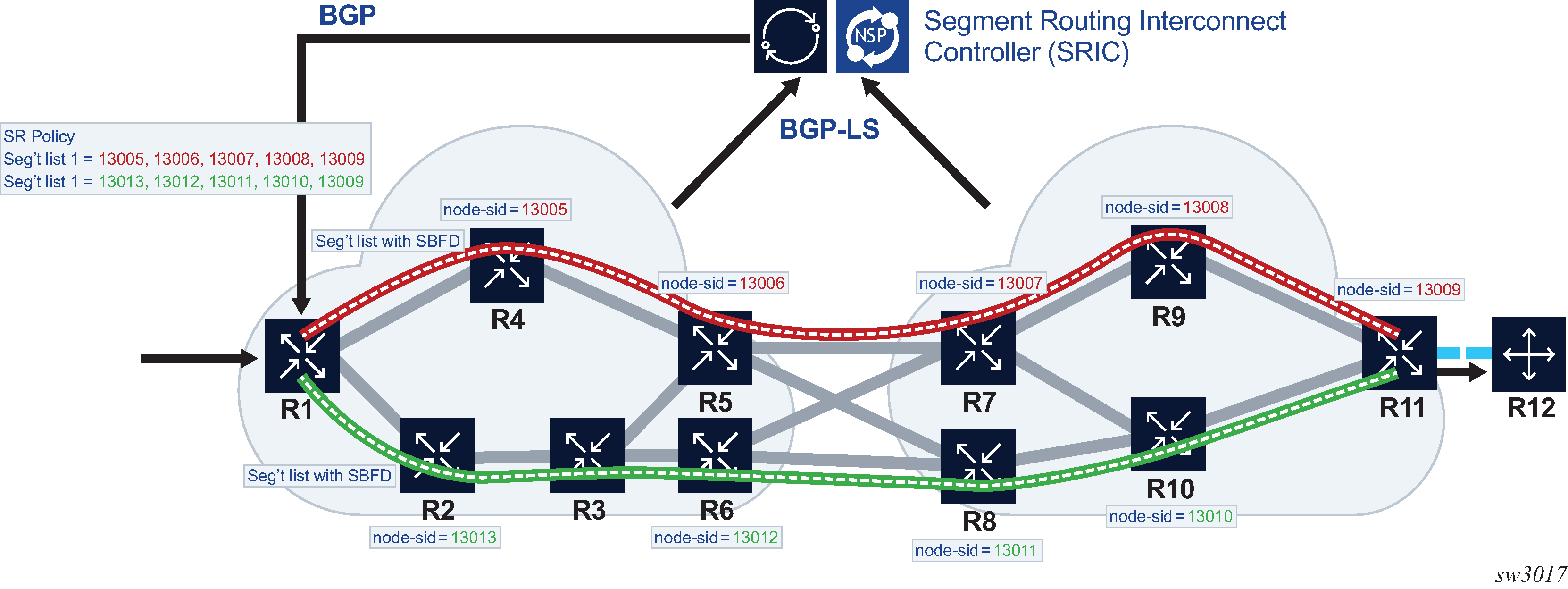
Linear mode
This mode is termed linear because it is similar in operation to traditional 1-for-1 linear protection switching. It is intended to allow one or more backup paths to protect a primary path, with fast failover between candidate paths. Uniform failover is supported between candidate paths of the same SR policy. Only one segment list from each of the top-three preference candidate paths is programmed in the IOM. All of the programmed candidate paths of a specified SR policy are in the same protection group. See Linear protected SR policy with S-BFD.
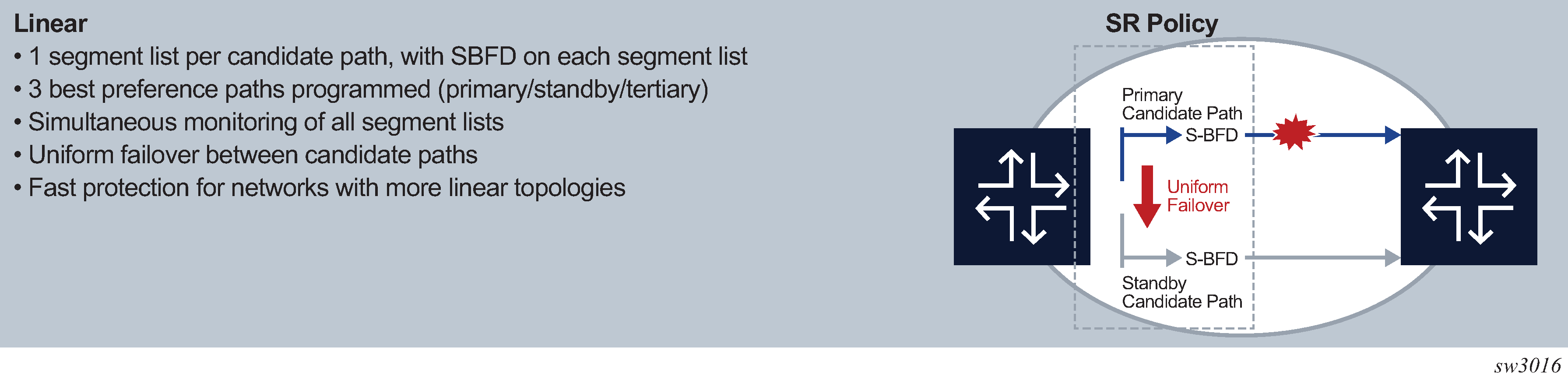
Detailed description
This section describes the S-BFD for SR policies, support for primary and backup candidate paths, and configuration steps for S-BFD and protection for SR policies.
S-BFD for SR policies
S-BFD is supported on segment lists for both static SR policies and BGP SR policies by binding a maintenance policy containing an S-BFD configuration to an imported SR policy route or a static SR policy. S-BFD packets are encapsulated on the SR policy segment lists in the same way as for SR-TE LSP paths. As in the case of SR-TE LSPs, the discriminator of the local node and a mapping to the far-end reflector node discriminators is first required. BFD sets the remote discriminator at the initiator of the S-BFD session based on a lookup in the S-BFD reflector discriminator using the endpoint address of the SR policy candidate path. A candidate path of an SR policy is only treated as available if the number of up S-BFD sessions equals or exceeds a configurable threshold.
Because this is set to 3 seconds, Nokia recommends that the transmit and receive control packet timers are set to no more than 1 second with a maximum multiplier of 3 for S-BFD sessions.
S-BFD control packet timers, that are configurable down to 10 ms, are supported for specific SR OS platforms with CPM network processor support.
S-BFD can be configured to operate in the following modes:
- Routed return path
In this mode, BFD packets are sent on each segment listed in the SR policy from the session initiator node toward the reflector node. The reflector node then sends the BFD reply packet back to the initiator using a routed return path.
- Controlled return path
This mode is enabled by configuring a return path label for the BFD session. In this mode, the router pushes an additional MPLS label on the S-BFD packets at the bottom of the stack and the BFD session operates in echo mode. The return path label refers to an MPLS binding SID of a reverse-path SR policy programmed at the far end of the SR policy. This SR policy can be used to forward S-BFD reply packets along an explicitly traffic-engineered path back to the initiator, avoiding the IGP shortest path. Different SR policies at the initiating end can be configured with different return path labels, referring to different SR policies at the far end, which can have segment lists with different paths, ensuring that the BFD reply packets from different head-end SR policy paths do not share the same outcome. S-BFD packets on these sessions bypass the reflector at the far end of the LSP. Therefore, there is no need to configure a reflector discriminator for these sessions.
Support for primary and backup candidate paths
End-to-end protection of static and BGP SR policies is supported using ECMP-protected or linear mode.
If an SR policy for a specified {headend, color, endpoint} is imported (by BGP) or configured (in the static case) and is selected for use, then the best (highest) preference candidate path is treated as the primary path while the next preference candidate preference policy is treated as the standby path. In linear mode, if a third path is present, then this is treated as a tertiary standby path. All of the valid segment lists for these are programmed in the IOM and made available for forwarding S-BFD packets, subject to a limitation in linear mode of one segment list per candidate path. In ECMP protected mode, the two best preference candidate paths are programmed in the IOM (up to 32 segment lists per path), while in linear mode, the three best preference candidate paths are programmed in the IOM (one segment list per candidate path).
In each case, segment lists of the best preference path are initially programmed as forwarding NHLEs while the others are programmed as non-forwarding. If the maximum number of programmed paths for a specified mode has been reached (for example, two for ECMP protected mode, and three for linear mode), and a consistent new path is received with a better preference than the existing active path, then this new path is only considered if or when the route for one of the current programmed paths is withdrawn or deleted. However, if the maximum number of programmed paths for the mode has not been reached, then the new path is programmed and any configured revert timer is started. The system switches to that better preference path immediately or when the revert timer expires (as applicable).
Failover is supported between the currently active path and the next best preference path if the currently active path is down because of S-BFD. Similar to the case of SR-TE LSPs, by default, if ECMP protected or linear mode is configured, the system switches back to the primary (best preference) SR policy path as soon as it recovers. This can happen when the number of up S-BFD sessions equals or exceeds a threshold and a hold-down timer has expired. However, it is possible to configure a revert timer to control reversion to the primary path.
All candidate paths of an SR policy must have the same binding SID when one of these two modes is applied.
Configuration of S-BFD and protection for SR policies
See the 7450 ESS, 7750 SR, 7950 XRS, and VSR OAM and Diagnostics Guide for more information about Steps 1 and 2. See Configuration of SR policy S-BFD and mode parameters, Application of S-BFD and protection parameters to static SR-policies, and Application of S-BFD and protection parameters to BGP SR-policies for details about Steps 3 through 5.
- Configure an S-BFD reflector and mapping parameters for the remote reflector under the configure>router>bfd>seamless-bfd context.
- Configure one or more BFD templates defining the BFD session parameters under the configure>router>bfd context.
- Configure protection and BFD parameters that are applied to SR policies in a named maintenance policy under the configure>router>segment-routing context.
- For static SR policies, apply a named maintenance policy to the static SR policy under the configure>router>segment-routing>sr-policies>static-policy context.
- For dynamic BGP SR policies, configure a policy statement entry to match on a specific route or a set of routes of type sr-policy-ipv4 with an action of accept and applying a named SR maintenance policy to them.
Configuration of SR policy S-BFD and mode parameters
S-BFD and protection mode command options are configured in a named maintenance policy. This is applied to SR policy paths that are imported by BGP as a policy statement action or by binding to a static SR policy configuration.
The following example displays the configuration of maintenance policies:
configure>router>segment-routing>
   maintenance-policy <name>
      bfd-enable
      bfd-template <name>
      mode {linear | ecmp-protected}
      threshold <number>
      return-path-label <label-value>
      revert-timer <timer-value>
      hold-down-timer <timer-value>
      no shutdown
The bfd-enable command enables or disables BFD on all of the segment lists of the candidate path that are installed in the datapath.
The bfd-template command refers to a named BFD template that must exist on the system.
The mode command specifies how to program the datapath and how the datapath should behave if the number of BFD sessions that are up is less than the threshold and the hold-down timer has expired. All of the paths in the set must have the same mode (see SR policy route and candidate path parameter consistency). All of the allowed segment lists of the SR policy path are programmed in the IOM. The default mode is none.
In both the linear mode and ecmp-protected modes, if two or more SR policy paths with the same {headend, color, endpoint} have the same mode, the highest preference path is treated as an effective primary path while the next highest path preference is treated as the standby path. If a third path is present in the linear mode, this is treated as a tertiary path and also programmed in the IOM.
In the ecmp-protected mode, all the segment lists of the top two best preference paths are programmed in the IOM. However, in linear mode, the lowest index segment list of each of the top three preference paths is programmed in the IOM and linear protection is supported between that set. All of the segment lists of the programmed paths are made available for forwarding S-BFD packets.
If the currently active path becomes unavailable because of S-BFD, the system fails over to the next best preference candidate path that is available. If all programmed candidate paths are unavailable, the SR policy is marked as down in TTM.
The linear mode supports uniform failover between candidate paths (policy routes) of the same SR policy. If linear mode is configured, the following rules apply:
-
Only one segment list is allowed per SR policy path. If more than one is configured, only the lowest index segment list is programmed in the datapath.
-
The top-3 best preference valid SR policy paths belonging to the same SR policy are programmed in the IOM and are assigned to the same protection group. Uniform failover is supported between these paths.
The threshold command configures the minimum number of S-BFD sessions that must be up to consider the SR policy candidate path to be up. If it is below this number, the SR policy candidate path is marked as BFD degraded by the system. The threshold command option is only valid in the ecmp-protected mode (a threshold of 1 is implicit in the linear mode).
The return-path-label command causes an additional MPLS label to be pushed at the bottom of the label stack for the S-BFD packet. It also enables echo mode for the S-BFD session. The return-path label refers to a binding SID on an SR policy or other MPLS path configured on the far-end router. The S-BFD packet is returned to the initiator using this MPLS return path, instead of being routed using the IGP path.
If the revert-timer command is configured, the router starts a revert timer when the primary path recovers (for example, after the number of S-BFD sessions that are up is ≥ threshold and the hold-down timer has expired) and switches back when the timer expires. If no revert-timer is configured, the system reverts to the primary path for the policy when it is restored.
If a secondary or tertiary path is currently active, and the revert timer is started (because of recovery of the primary path), but the secondary path subsequently goes down because the number of up S-BFD sessions is less than the threshold, and no other better preference standby path is available, the router reverts immediately to the primary path. However, if a better preference standby path is available and up, the revert timer is not canceled and the system switches to the better preference standby path and switches back to the primary path when the revert timer expires. If the hold-down timer is currently active on a better-preference path, the system immediately switches to the primary path. If the system needs to switch to the primary path but the hold-down timer is still active on the primary path, the system cancels the timer and switches immediately.
The hold-down-timer command is intended to prevent bouncing of the SR policy path state if one or more BFD sessions associated with segment lists flaps and causes the threshold to be repeatedly crossed in a short period of time. The hold-down timer is started when the number of S-BFD sessions that are up drops below the threshold. The SR policy path is not considered to be up again until the hold-down timer has expired and the number of S-BFD sessions that are up equals or exceeds the threshold.
A maintenance policy can only be deleted or a value changed if the maintenance policy is administratively disabled (shutdown). A maintenance policy can only be enabled if the bfd-enable, bfd-template, and mode commands are configured. All associated SR policy paths are deleted from the IOM if a maintenance template is shutdown.
Application of S-BFD and protection parameters to static SR-policies
A named maintenance policy is applied to a static SR policy using the maintenance-policy command as follows:
config router segment-routing sr-policies
         static-policy <name>
            head-end local
            binding-sid <number>
            maintenance-policy <name>
            ...
A maintenance policy can only be configured if the static SR policy head-end is set to local. Policies with an IP address that is not local to the node are not programmed in the SR database and cannot have S-BFD sessions established on them by this node because they are not the head end for the SR policy path.
S-BFD needs an endpoint address for the session so that the S-BFD reflector discriminator can be looked-up as a part of the session addressing. A maintenance policy cannot be configured on an SR policy with a null endpoint.
Application of S-BFD and protection parameters to BGP SR-policies
S-BFD and protection parameters can be applied to matching imported SR policy routes. Match criteria in the route import policy for the color, endpoint and route distinguisher of a policy enable matching on a specific SR policy route for family sr-policy-v4 and sr-policy-v6 types.
For example, matching a unique SR policy requires the following fully qualified set of match criteria:
configure router policy-options
   policy-statement <name>
      entry <id>
         from family sr-policy-ipv4
         from distinguisher <rd-value>
         from color <color>
         from endpoint <ip-address>
However, users may only require more general match criteria (for example, to apply the same maintenance template to all imported SR policy IPv4 routes, irrespective of color or endpoint).
An SR policy maintenance template is applied to matching SR policy routes using the sr-maintenance-policy action commands.
configure router policy-options
   policy-statement <name>
      entry <id>
         from family sr-policy-ipv4
         ...
         action accept
           sr-maintenance-policy <name>
Maintenance policy statements are applicable as actions on a specific entry or as the default action.
The named SR maintenance policy must exist on the system when the commit is executed for the routing policy. If parameterization of actions is used and the named SR maintenance policy exists, the router still validates.
A change in policy options action deletes all programmed paths for that route and based on the new action, re-downloads applicable routes to the IOM.
SR policy route and candidate path parameter consistency
An SR policy consists of a set of one or more candidate paths. Each candidate path may be described by an SR policy route, that may be a static SR policy that is configured under the config>router>segment-routing>sr-policies context, or a dynamic route imported by BGP. The router checks the consistency of the following BFD and protection parameters across all of the SR policy routes for a specified SR policy.
{Maintenance-policy existence}
    bfd-enable
    bfd-template <name>
    mode {linear | ecmp-protected}
    revert-timer <timer-value>
Maintenance-policy existence covers the case where the existing programmed route is an SR policy with no maintenance policy, and the new route has a maintenance policy, and the other way around.
Consistency is enforced across all of the static SR policy candidate paths and dynamic SR policy routes that make up a segment routing policy. Because SR policy routes or paths are imported sequentially and cannot be considered together, inconsistencies are handled as follows:
First policy route imported/configured:
Check: valid set of parameters
Action: If OK, program in data path and activate

Second policy route imported/configured:
Check: valid set of parameters, consistency with existing activated policy route
Action If OK, program in data path and activate, else hold in CPM but do not program

Third policy route imported/configured:
Check: valid set of parameters, consistency with existing activated policy route (s)
Action If OK, program in data path and activate, else hold in CPM but do not program
Inconsistent policy routes (paths) are only programmed if their parameters are valid and any programmed routes for that SR policy are deleted.
By using the same maintenance policy for all of the SR policy's routes, inconsistencies between the BFD and protection parameters of SR policy routes belonging to a specified SR policy can be avoided.
Traffic statistics for segment routing policies
SR policies provide the ability to collect statistics for ingress and egress traffic. In both cases, traffic statistics are collected without any forwarding class or QoS distinction.
Traffic statistics collection is enabled as follows:
-
config>router>segment-routing>sr-policies>ingress-statistics
Ingress traffic collection only applies to binding-sid SR policies as the statistic index is attached to the ILM entry for that label. The traffic statistics provide traffic for all the instances that share the binding SID. The statistic index is released and statistics are lost when ingress traffic statistics are disabled for that binding SID, or the last instance of a policy using that label is removed from the database.
-
config>router>segment-routing>sr-policies>egress-statistics
Egress traffic statistics are collected globally, for all policies at the same time. Both static and signaled policies are subject to traffic statistics collection. Statistic indexes are allocated per segment list, which allows for a fine grain monitoring of traffic evolution. Also, statistic indexes are only allocated at the time the segment list is effectively programmed. However, the system allocates at most 32 statistic indexes across all the instances of a policy. Therefore, in the case where an instance of a policy is deprogrammed and a more preferred instance is programmed, the system behaves as follows:
-
If the segment list IDs of the preferred instance are different from any of the segment list IDs of any previously programmed instance, the system allocates new statistic indexes. While that condition holds, the statistics associated with a segment list of an instance strictly reflect the traffic that used that segment list in that instance.
-
If some of the segment list IDs of the preferred instance are equal to any of the segment list IDs of any previously programmed instance, the system reuses the indexes of the preferred instance and keeps the associated counter value and increment. In this case, the traffic statistics provided per segment list not only reflect the traffic that used that segment list in that instance. It incorporates counter values of at least another segment-list in another instance of that policy.
-
In all cases, the aggregate values provided across all instances truly reflect traffic over the various instances of the policy.
Statistic indexes are not released at deprogramming time. They are, however, released when all the instances of a policy are removed from the database, or when the egress-statistics command is disabled.
Equal/Old means the following.
-
If the prefix is duplicate, it is equal and no change is needed. Keep the old LSA/LSP.
-
If the prefix is not duplicate, still keep the old LSA/LSP.
Equal/New means the following.
-
If the prefix is duplicate, it is equal and no change is needed. Keep the old LSA/LSP.
-
If the prefix is not duplicate, pick a new prefix and use the new LSA/LSP.