Segment routing with IPv6 data plane (SRv6)
Introduction to segment routing with IPv6 data plane (SRv6)
Segment routing steers packets by encoding the packet-processing instructions for each intermediate and destination router directly in the packet header.
The datapath pushes a list of instructions in the form of Segment Identifiers (SIDs) onto the packet to forward the payload packet directly to the destination using the shortest path or using source routing via one or more transit routers. Each router that terminates a SID in the segment list performs the instructions related to that SID.
Segment routing standards specify the following two methods for programming the datapath of the encapsulated packet:
-
Segment Routing MPLS (SR-MPLS)
The SID is encoded in 32 bits and programmed as an MPLS label and provides a tunnel to both IPv4 and IPv6 destinations. See Segment routing with MPLS data plane (SR-MPLS).
- Segment Routing IPv6 (SRv6)
The SID is encoded in 128 bits and programmed as an IPv6 address and provides a tunnel to IPv6 destinations.
SRv6 datapath encapsulation models each SID using a 128-bit address. In shortest path routing, the destination SID is encoded in the Destination Address (DA) field of the outer IPv6 header. In source routing, the SIDs of the nodes the packet must visit are encoded as a SID list in a Segment Routing Header (SRH), a type of routing header defined in RFC 8986 and compliant with RFC 8200. The next SID in a segment list to which the packet is to be forwarded is copied from the SRH into the DA field of the outer IPv6 header.
SRv6 provides more than IPv6 transport with shortest path and source-routing capabilities; it provides a framework for programmability of IPv6 networks that takes advantage of the large IPv6 address space.
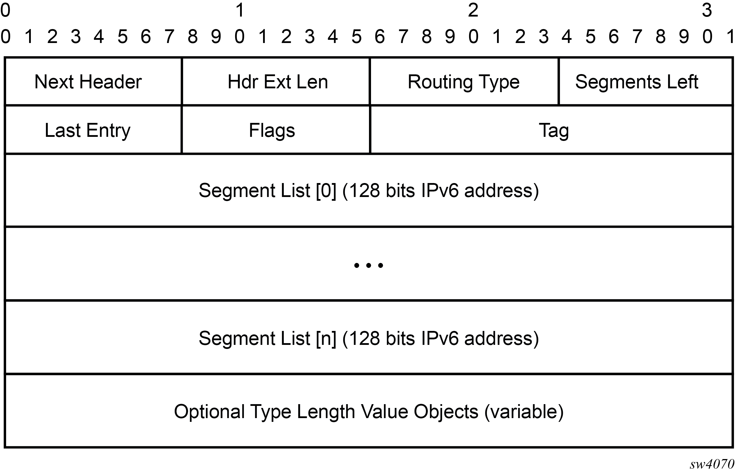
The following figure shows the SRv6 SRH format and fields (excerpt from RFC 8986).
| Field name | Description |
|---|---|
|
Next Header |
Defined in RFC8200, Section 4.4 |
|
Hdr Ext Len |
Defined in RFC8200, Section 4.4 |
|
Routing Type |
4 |
|
Segments Left |
Defined in RFC8200, Section 4.4 |
|
Last Entry |
Contains the index (zero based), in the Segment List, of the last element of the Segment List |
|
Flags |
RFC8754, Section 8.1 creates an IANA registry for new flags to be defined (see 8-bits of flags). |
|
Tag |
Tag a packet as part of a class or group of packets; for example, packets sharing the same set of properties. When Tag is not used at the source, it must be set to zero on transmission. When Tag is not used during SRH processing, it is ignored. Tag is not used when processing the SID, as defined in RFC8754, Section 4.3.1. |
|
Segment List[0..n] |
128-bit IPv6 addresses representing the nth segment in the Segment List. The Segment List is encoded starting from the last segment of the SR policy. That is, the first element of the Segment List (Segment List[0]) contains the last segment of the SR policy, the second element contains the penultimate segment of the SR policy, and so on. |
|
TLV |
Type Length Value (TLV); see RFC8754, Section 2.1, and SRv6 SID encoding. |
The following figure shows the Flags field.
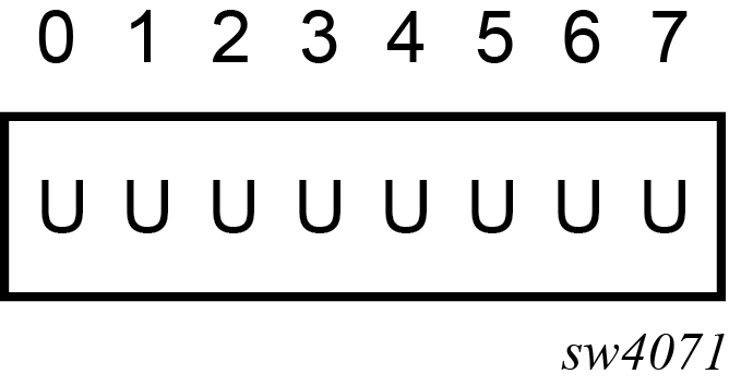
The following table lists the flags.
| Flag | Description |
|---|---|
|
U |
Unused and for future use. Must be 0 on transmission and ignored on receipt. |
The following figure shows the SRv6 SID encoding format and fields.
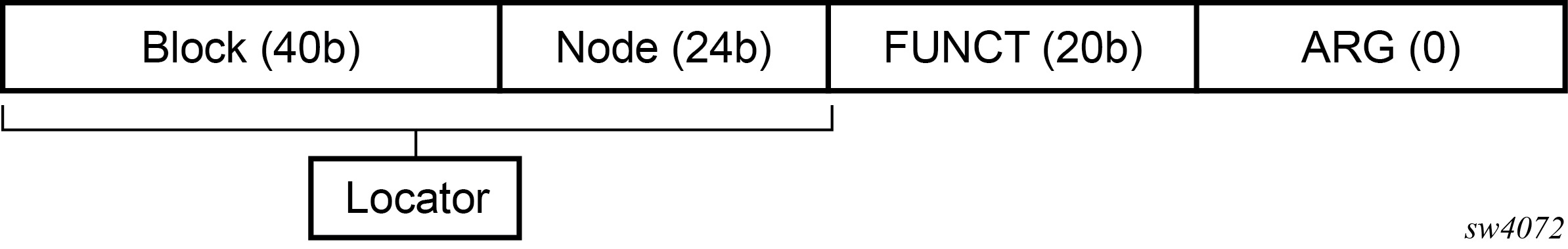
The 128-bit address of an SRv6 SID is split into a three-field structure: (LOCATOR:FUNCTION:ARGUMENT). The size of these fields is configurable. This structure is used to encode both the transport, or reachability, information in the LOCATOR field, and the SID function information in the FUNCTION field.
- LOCATOR field
- encodes the transport or reachability information
- FUNCTION field
- encodes a node SID function (End SID), an adjacency SID function (End.X SID), or a service SID function that is the equivalent of a service label in SR-MPLS
- ARGUMENT field
- can be used to carry limited service or application metadata; typical use is to encode a value that identifies the source Ethernet Segment for EVPN services that require multi-homing or Etree procedures
The following figure shows the operation of the data and control planes when an IP-VPN route is resolved to an SRv6 tunnel.
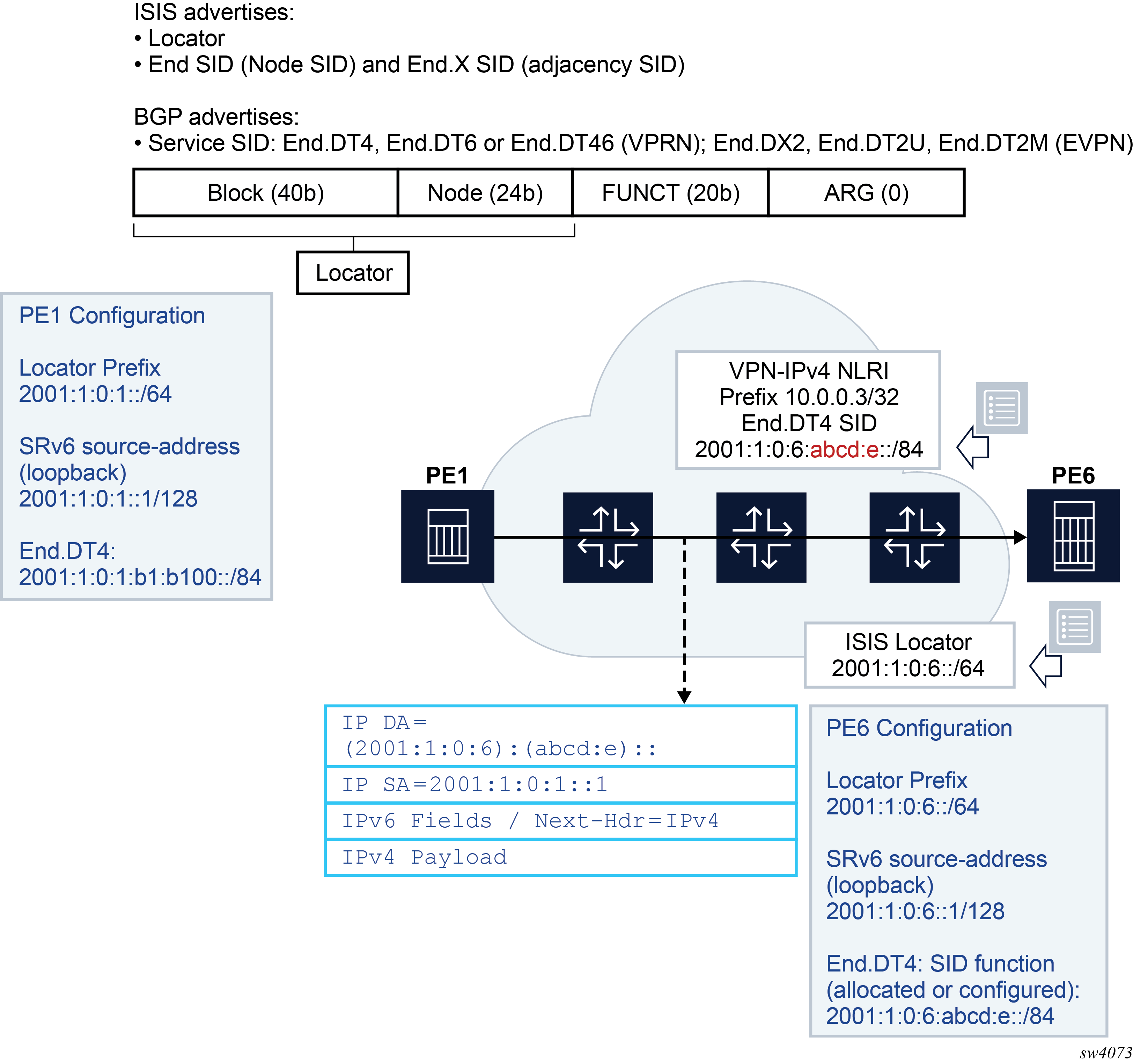
The PE6 egress router advertises in IS-IS the locator route that contains its locator prefix and optionally a local node SID (End). It also advertises the SID of each adjacency (End.X) to its IS-IS neighbors.
The locator prefix provides the route to reach PE6 and is used by other routers to forward an SRv6 packet destined for any SID owned by PE6. Other routers use the End and End.X SIDs to create the repair tunnel for the Remote LFA and TI-LFA backup paths.
In BGP, PE6 advertises a VPN-IPv4 route and includes the service SID End.DT4 (equivalent in SR-MPLS to the service label in the label per-VRF model). In SRv6, the difference is the End.DT4 SID contains both the function value that identifies the specific VRF-ID in PE6 and the locator prefix that provides the reachability to router PE6.
The PE1 router resolves the received VPN-IPv4 route by validating the next hop and checking the reachability of the locator prefix of PE6 in the routing table. When PE1 receives an IPv4 packet from a CE node, it pushes an outer IPv6 header that contains the End.DT4 SID in the DA field and looks up the address in the routing table. The packet is then forwarded to one of the next hops of the route of the locator prefix of PE6.
SR OS also supports micro-segment SRv6. The system supports operating in both modes (regular and micro) concurrently on the same platform, but requires the SIDs of each type to come from different SID blocks.
Micro-segment SRv6 provides the same functionality as regular SRv6 but uses 16-bit SIDs while regular SRv6 uses 128-bit SIDs. The 16-bit SIDs are referred to as micro-SIDs.
Micro-SIDs follow the general structure of regular SIDs (LOCATOR:FUNCTION:ARGUMENT), although the following differentiates the two.
In regular SRv6, identifiers are assigned to nodes and form, together with the SID block, the LOCATOR part of any SID. SIDs are assigned per node and associated with a specific behavior (or function), resulting in the LOCATOR:FUNCTION structure. Micro-segment SRv6 introduces a specific function (uN) which acts both as a locator (when combined with the block) and as a function (corresponding to END in regular SRv6) but without using any FUNCTION bits. In other words, the LOCATOR and END constructs of regular SRv6 correspond to a unique construct in micro-segment SRv6: <block><uN>.
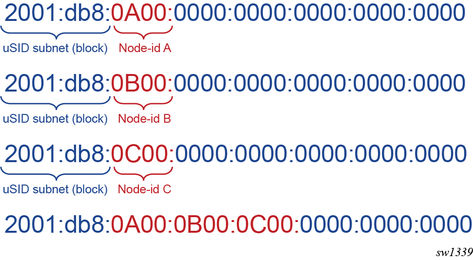
Micro-segment SRv6 allows micro-SIDs to be compressed. Compression consists in coalescing several micro-SIDs into a 128-bit structure called a container.
Compression of three micro-SIDs in a container shows three micro-SIDs, each identifying a different node in a network. The figure shows the result of compressing these three micro-SIDs in a container. Compression is possible because all micro-SIDs belong to the same block.
A container can be placed in the DA field of an IPv6 header and in a segment of the segment list of an SRH.
Compression allows the router to build longer paths with less overhead than with regular SRv6. However, it leads to specific datapath behaviors. See Datapath support for more information.
Micro-segment SRv6 introduces specific micro-segment SRv6 functions that correspond to functions defined for regular SRv6 (see Micro-segment SRv6 and Overview of the BGP requirements).
In general, any SR OS capability that applies to regular SRv6 also applies to micro-segment SRv6. In the documentation, only the differences are highlighted and commonalities are not repeated using micro-segment SRv6 specific terminology.
Configuring the locator and SIDs
Configuring the SRv6 locator and SIDs
This section describes configuration of the SRv6 locator.
An SRv6 SID is a 128-bit IPv6 address which follows the structure defined by RFC 8986:
SRv6 SID={LOCATOR:FUNCTION:ARGUMENT}.
The user must configure the main SRv6 subnet for this node. This is the locator and is essentially an IPv6 subnet (prefix and length) that provides reachability (longest prefix match) to all the SIDs originated by this node. The prefix part is encoded in the LOCATOR field of the SRv6 SID.
The locator is further subdivided into a SID block and a node ID. For example, locator 3FFE:0:0:A1::/64 has a SID block of 3FFE:0 and node ID of 0:A1.
All nodes participating in an SRv6 domain must draw their locator and SIDs from the same SID block. In the previous example, the SID block is subnet 3FFE:0::/32.
The following is the CLI structure for the configuration of the SRv6 locator.
Example: Configuration structure of the SRv6 locator (classic CLI)
configure+--router
   +--segment-routing
      +--segment-routing-v6
         +--origination-fpe* <fpe>
         +--source-address <ipv6-address>
         +--locator* <locator-name>
            +--admin-state (enable|disable)
            +--termination-fpe <fpe>
            +--algorithm <0, 128-255>
            +--prefix
               +--ip-prefix <ipv6-address/prefix-length>
            +--block-length <0-96>
            +--function-length <16 | 20-96>
            +--label-block <block-name>
            +--static-function
                      +--max-entries <integer>
                      +--label-block <block-name>
Example: Configuration structure of the SRv6 locator (MD-CLI)
*[pr:/configure router "Base" segment-routing segment-routing-v6 locator "test"]
A:admin@test# tree detail
+-- admin-state <keyword>
+-- algorithm <number>
+-- apply-groups <reference>
+-- apply-groups-exclude <reference>
+-- block-length <number>
+-- function-length <number>
+-- label-block <reference>
+-- prefix
|   +-- ip-prefix <global-unicast-ipv6-address-and-prefix>
+-- static-function
|   +-- label-block <reference>
|   +-- max-entries <number>
+-- termination-fpe <reference>
+-- origination-fpe <reference>
+-- source-address <global-unicast-ipv6-address>
The two reserved label ranges (locator>label-block and locator>static-function>label-block) are mutually exclusive.
If locator>static-function>label-block is configured, then the labels associated with the service functions are drawn as follows:
-
from the label block for static service function
- from the dynamic label range for dynamic service functions
If locator>label-block is configured, labels associated with service functions are drawn from the label block for both static and dynamic service functions.
Configuring a function length of 16 requires the use of locator>label-block. Function lengths of 16 are not supported on locator>static-function>label-block.
One locator is required for algorithm 0 and one for each IGP flexible algorithm (128-255). The same locator can be shared by multiple IGP instances for the same algorithm number.
The locator prefix, example 3FFE:0:0:A1::/64, is advertised in the SRv6 Locator TLV in IS-IS in both algorithm 0 and any configured flexible algorithm number as defined in draft-ietf-lsr-isis-srv6-extensions. It is also advertised as a prefix in IP Reach TLV (ISIS TLV 236) in algorithm 0, so the routers that do not support SRv6 can still route the packet to the next hop of the locator and eventually to its destination node.
The FUNCTION field is user-configurable, but the ARGUMENT field is set to all zeros and is not configurable. The ARGUMENT length must be signaled as zero in ISIS End and End.X SIDs and in BGP service SIDs. Also, the sum of the LOCATOR and FUNCTION lengths must be less than or equal to 128.
Within algorithm 0 and each IGP flexible algorithm, the locator function (FUNCTION field) assigns the value of the End SID and End.X SID, that corresponds to the node SID and adjacency or adjacency SET SID respectively.
The locator function also assigns the value of the service SIDs owned by this node and advertised in the BGP control plane (End.DT4, End.DT6, End.DT46, and End.DX2).
The FUNCTION field can be subdivided into a static and a dynamic subrange. The user can draw from the static subrange to manually assign an SRv6 SID to a node, a local adjacency, or a service. IS-IS and BGP can draw from the dynamic subrange to assign a SID to a local adjacency or a service. The SID of an adjacency to a IS-IS neighbor, over a broadcast interface (LAN End.X), is always dynamically assigned and is not configurable.
The following CLI enables the allocation of a SRv6 SID function value. Manual allocation of a static function value is supported with the node (End SID), adjacency over a P2P interface (End.X SID), and a service SID. Auto-allocation is supported with an adjacency over a P2P interface (End.X SID) and a service SID.
Example: Allocation of a SRv6 SID value (classic CLI)
configure
+--router
+---segment-routing
|   +---segment-routing-v6
|   |   +--- base-routing-instance
|   |   |   |   locator <locator-name>
|   |   |   |   +---function
|   |   |   |   |   |   end <integer>
|   |   |   |   |   |   +---srh-mode <psp | usp>
|   |   |   |   |   +---end-x-auto-allocate <psp|usp> <protected|unprotected>
|   |   |   |   |   +---end-x <integer>
|   |   |   |   |   |   +---interface <name>
|   |   |   |   |   |   +---srh-mode <psp | usp>
|   |   |   |   |   |   +---protection <protected|unprotected>
|   |   |   |   |   +---end-dt4 [<integer>]
|   |   |   |   |   +---end-dt6 [<integer>]
|   |   |   |   |   +---end-dt46 [<integer>]
Example: Allocation of a SRv6 SID value (MD-CLI)
[pr:/configure router "Base" segment-routing segment-routing-v6]
A:admin@test# tree detail
+-- base-routing-instance
|   +-- apply-groups <reference>
|   +-- apply-groups-exclude <reference>
|   +-- locator <reference>
|       +-- function
|           +-- end <number>
|           |   +-- srh-mode <keyword>
|           +-- end-x-auto-allocate <keyword> protection <keyword>
|           +-- end-x <number>
|           |   +-- interface-name <reference>
|           |   +-- protection <keyword>
|           |   +-- srh-mode <keyword>
|           +-- end-dt4
|           +-- end-dt46
|           +-- end-dt6
Configuring the micro-segment locator and SIDs
configure router segment-routing segment-routing-v6 micro-segment
configure router segment-routing segment-routing-v6 micro-segment-locator- block-length
This command provides the same function as for regular SRv6. The value must be the same on every platform network wide.
- global-sid-entriesThis command defines the maximum number of unique micro-segment locators that can be configured network wide. The value must be the same on every platform network wide. This command splits in two the total number of values that can be encoded in 16 bits. A 16-bit field allows values in the range 0x0000 to 0xFFFF. Configuring 16 (default value) for the global-sid-entries value splits that range into the following:
- 0x0000 to 0x3FFF for global identifiers
- 0x4000 to 0xFFFF for local identifiers
- sid-length
This command defines the length of micro-SIDs. The only supported value is 16 (bits).
- label-block
The reserved label block serves both static and dynamic service functions. The theoretical maximum number of functions in micro-segment SRv6 is 216. A label block providing more values than the theoretical maximum leads to a waste of labels. Because in practice, the number of local functions is less than (216 - global-sid-entries), a label-block should not need exceed that value.
- ip-prefix
The IP prefix configures the block as an IPv6 address. The prefix-length value must be equal to the block-length.
- block
This command configures a reference (by name) to a previously configured block.
- max-entries
This command sets the maximum number of static functions the user needs.
- un value
This command creates a node identifier as an IPv6 address composed of the block part followed by a 16-bit SID. The value of the SID is the nth global SID entry. The configured value must be unique network wide. This value is configured as part of the locator because it acts as a locator.
- The user configures SIDs that are specific to micro-segment SRv6 (uA, uDT4, uDT6, uDT46).
- The configured value only needs to be unique on the system and not network wide.
- The resulting SID value is derived from the local range.
- Although the uN function is equivalent to the regular SRv6 END function, it is not configurable under the Base instance because it is configured in the micro-segment-locator context.
IS-IS control plane extensions
The following CLI enables SRv6 in the IS-IS instance and assigns a locator to each algorithm (zero or flexible algorithm).
configure
+--router
+---isis <0..31>
|   +---segment-routing-v6
|   |   +---locator <locator-name>
|   |   |   +--level-capability <level-1|level-2|level-1/2>
|   |   |   +---level <1|2>
|   |   |   |   +---metric <1..16777215>
|   |   |   +---tag <1..4294967295>
|   |   +---shutdown
|   |   |   no shutdown
The IS-IS control plane extensions in support of SRv6 are defined in draft-ietf-lsr-isis-srv6-extensions.
The IS-IS control plane advertises the SRv6 capabilities sub-TLV and the SRv6 Locator TLV. The latter includes the End function sub-TLV (equivalent to the prefix SID sub-TLV in SR-MPLS). IS-IS also advertises the End.X function sub-TLV (equivalent to the adjacency SID sub-TLV for a P2P link and a LAN in SR-MPLS) in the Extended IS reachability TLV (top-level link TLV).
The weight field in the End.X or LAN End.X sub-TLVs is not filled in on transmit and is ignored on receipt of the link TLV.
The following table describes the supported IS-IS SRv6 TLVs in SR OS.
| SRv6 TLV/sub-TLV | Codepoint | IS-IS context TLV | Description | SR OS support |
|---|---|---|---|---|
|
SRv6 Capabilities sub-TLV |
25 |
Router CAPABILITY TLV (242) |
Indicates SRv6 support |
Yes |
|
SR-Algorithm sub-TLV |
19 |
Router CAPABILITY TLV (242) |
Indicates base algorithm 0 and Flex-Algo 128-255 support |
Yes |
|
Maximum Segments Left MSD Type sub-TLV |
41 |
Router CAPABILITY TLV (242) |
Indicates how deep a node terminating current segment can process the SRH (Segments-Left field) to move the next SID to outer IPv6 header DA field |
Yes (advertised value = 10 SIDs) Received TLV is displayed in Link State database but is not used for any purpose. |
|
Maximum End Pop MSD Type sub-TLV |
42 |
Router CAPABILITY TLV (242) |
Maximum number of SIDs in a SRH when a node removes SRH (PSP or USP modes of SRH) |
Yes (advertised value = 9 SIDs) Received TLV is displayed in Link State database but is not used for any purpose. |
|
Maximum H.Encaps MSD type sub-TLV |
44 |
Router CAPABILITY TLV (242) |
Indicates maximum number of SIDs in an SRH a router can push when forwarding a IP or L2 packet over a SRv6 policy |
Yes (advertised value = 1 SID) Received TLV is displayed in Link State database but is not used for any purpose. |
|
Maximum End D MSD Type Sub-TLV |
45 |
Router CAPABILITY TLV (242) |
Maximum number of SIDs in a SRH when a node removes SRH and performs the End.DX2/4/6 or End.DT4/6 function (USP mode of SRH) |
Yes (advertised value = 9 SIDs) Received TLV is displayed in Link State database but is not used for any purpose. |
|
SRv6 Locator TLV |
27 |
Is a top Level IS-IS TLV |
Advertises the locator prefix configured on this node to terminate SIDs in algorithm 0 and flex-algo 128-255 |
Yes |
|
SRv6 End SID sub-TLV |
5 |
SRv6 Locator TLV |
Advertises the SID for the endpoint or End function (equivalent of prefix SID sub-TLV in SR-MPLS) |
Yes |
|
Prefix Attribute Flags Sub-TLV |
4 |
SRv6 Locator TLV (also in IP Reach TLV 236) |
Provides attributes of a prefix which is leaked between IS-IS levels |
Yes |
|
SRv6 End.X SID sub-TLV |
43 |
Top level Extended IS reachability TLV (22) |
Advertises the SID for the adjacency over a P2P link (equivalent of adjacency SID sub-TLV for P2P link in SR-MPLS) |
Yes |
|
SRv6 LAN End.X SID sub-TLV |
44 |
Top level Extended IS reachability TLV (22) |
Advertises the SID for the adjacency over a LAN (equivalent of adjacency SID sub-TLV for LAN in SR-MPLS) |
Yes |
|
SRv6 SID Structure Sub-Sub-TLV |
1 |
SRv6 End SID Sub-TLV, SRv6 End.X SID Sub-TLV, SRv6 LAN End.X SID Sub-TLV |
Provides the length of each field (Block, Locator, Function, and Argument) of the SRv6 SID it is advertised with |
No SR OS does not advertise this sub-sub-TLV. If received from other vendor's implementation, it is not displayed in Link-State database and is also not propagated with the locator TLV. |
When both SR-MPLS and SRv6 are enabled on the same IS-IS instance, an MPLS node SID cannot be configured for a prefix of the locator or an End SID. This is because the SRv6 locator subnet cannot be added to a network interface and an MPLS node SID is configurable against a network interface only.
However, both the SRv6 locator route and the SR-MPLS tunnel are programmed if IS-IS receives from a third-party router implementation, a /128 prefix that has both a locator TLV and a prefix SID TLV (with node flag enabled). If the prefix SID is for a subnet larger than /128, only the locator route is programmed and the SR-MPLS tunnel is not.
Each SID function encoded in a SRv6 SID has its own endpoint behavior codepoint as listed in SRv6 SID function endpoint behavior codepoints.
SR OS advertises service SID functions in the BGP control plane only as described in BGP Service control plane extensions.
For the SRH processing and removal at the SID termination , the following modes of operation are associated with the termination of the End or End.X SID. These modes are sometimes referred to as SID flavours and IS-IS assigns a unique codepoint for each mode of the End or End.X SID of a given adjacency.
- Basic or unflavored SRH mode
- The router that terminates an End or End.X SID and the Segments-Left field in the received packet is 0 before decrementing, keeps the SRH in the packet, and processes the packet identified by the next-header in the SRH. Typically, the next-header indicates another SRH and the packet is then forwarded based on the lookup of that next-SID; SR OS does not support this mode.
- Ultimate Segment Popping (USP) SRH mode
- The egress PE terminates the last segment in the outer IPv6 header, removes the SRH and processes the inner service or control plane packet as indicated by the SRH Next-Header field. SR OS supports this mode.
- Penultimate Segment Popping (PSP) SRH mode
- The router that terminates the End or End.X segment before the last in the segment list, meaning the Segments-Left field before decrementing has a value of 1, removes the SRH on behalf of the egress PE. SR OS supports this mode.
- PSP&USP SRH mode
- This is a combination of both the USP and PSP modes. The router that terminates the End or End.X segment applies the corresponding behavior for value 0 and 1 of the Segments-Left field. SR OS does not support this mode.
- Ultimate Segment Decapsulation (USD) SRH mode
- This is a variant of the USP in which the node removes the SRH and moves directly to process the inner IPv6 packet as indicated by the SRH Next-Header field.. This mode is used to terminate a TI-LFA or a Remote LFA repair tunnel originated with the H.Encaps.Red encapsulation. SR OS does not support this mode.
| SID function endpoint behavior | Codepoint RFC 8986 |
SID type: End.SID | SID type: End.X SID | SID type: LAN End.X SID | Advertising protocol | Supported |
|---|---|---|---|---|---|---|
|
End (PSP, USP, USD) |
1-4, 28-31 |
Yes |
No |
No |
IS-IS |
Yes IS-IS only {PSP value=2, USP value=3} |
|
End.X (PSP, USP, USD) |
5-8, 32-35 |
No |
Yes |
Yes |
IS-IS |
Yes IS-IS only {PSP value=6, USP value=7} } |
|
End.T (PSP, USP, USD) |
9-12, 36-39 |
Yes |
No |
No |
IS-IS |
No1
|
|
End.DX6 |
16 |
No |
Yes |
Yes |
BGP or IS-IS |
No1 |
|
End.DX4 |
17 |
No |
Yes |
Yes |
BGP or IS-IS |
No1 |
|
End.DT6 |
18 |
Yes |
No |
No |
BGP or static |
Yes1 BGP only. |
|
End.DT4 |
19 |
Yes |
No |
No |
BGP or static |
Yes1 BGP only. |
|
End.DT46 |
20 |
Yes |
No |
No |
BGP or static |
Yes1 BGP only. |
|
End.DX2 |
21 |
Yes |
No |
No |
BGP or static |
Yes1 BGP only. |
Micro-segment SRv6
configure router isis segment-routing-v6 micro-segment-locatorThe following table lists the TLVs that micro-segment SRv6 supports on top of the TLVs described in SRv6 IS-IS TLVs.
| SRv6 TLV/sub-TLV | Codepoint | IS-IS context TLV | Description | SR OS support |
|---|---|---|---|---|
|
SRv6 SID Structure sub-sub-TLV |
1 |
SRv6 uN SID Sub-TLV, SRv6 uA SID Sub-TLV, SRv6 LAN uA SID Sub-TLV |
Provides the length of each field (block, locator, function, and argument) of the SRv6 uSID it is advertised with |
Yes |
The following table lists the endpoint behavior codepoint for each SID function encoded in a micro-segment SRv6 SID.
| SID function endpoint behavior | Codepoint | SID type: End.SID | SID type: End.X SID | SID type: LAN End.X SID | Advertising protocol | Supported |
|---|---|---|---|---|---|---|
|
uN |
42-50 |
Yes |
No |
No |
IS-IS |
Yes 2 IS-IS only {values: 44, 45} |
|
uA |
51-59 |
No |
Yes |
Yes |
IS-IS |
Yes 2 IS-IS only {values: 53, 54} |
SRv6 Support in IS-IS Multi-Topology
This feature extends the support of SRv6 to multi-topology IPv6 (MT2) in IS-IS.
Feature configuration
- classic
CLI
configure +--router +--isis <isis-instance> +--segment-routing-v6 +---no adj-sid-hold | adj-sid-hold <seconds> +---locator <name> | no locator <name> | +---level {1|2} | | +---metric <metric> | | | no metric | +---level-capability {level-1|level-2|level-1/2} | | no level-capability | +---multi-topology [mt0] [mt2] | | no multi-topology | +---no tag | | tag <tag> +---shutdown | no shutdown - MD-CLI
configure
+--router
   +--isis <isis-instance>
      +--segment-routing-v6
         +-- adj-sid-hold <seconds>
         +--admin-state (enable|disable)
         +--locator <locator-name>
            +--level-capability <level-1|level-2|level-1/2>
            +--level <1|2>
               +--metric <metric>
            +--tag <tag>
        +---multi-topology [mt0] [mt2]
The user can enable one or more SRv6 local locators in a specific IS-IS instance. Each locator can be enabled in a single topology of an IS-IS instance, topology 0 (MT0) or topology 2 (MT2). By default, a locator name added to an IS-IS instance is enabled in MT0. A local locator can be used in multiple IS-IS instances and can be assigned to at most one IPv6 topology independently within each IS-IS instance.
IS-IS control plane changes
When a local locator is enabled in the MT2 IPv6 unicast topology of an IS-IS instance, IS-IS advertises the following routes:
- The prefix itself in a top level Multi-Topology Reachable IPv6 Prefixes TLV type 237 with the MT-ID field set to 2.
- A top level locator TLV (top level SRv6 Locator TLV type 27) that contains the locator prefix as well as the End SID sub-TLVs associated with this local locator. The locator TLV is advertised with the MT-ID field set to 2.
- The End.X or LAN End.X sub-TLV in the top level multi-topology Extended IS Reachability TLV (222).
- The TE link application specific attributes sub-TLV in the top level multi-topology Extended IS Reachability TLV (222). This is to support the flex-algo feature.
- The Application-Specific Shared Risk Link Group (SRLG) TLV (238)The following table summarizes the new or modified TLVs in support of SRv6 in IS-IS MT2.
Table 7. SRv6 IS-IS MT2 TLVs Multi-topology TLV Codepoint IS-IS context TLV Description SR support Multi-topology IPv6 Reach TLV 237 Is a top Level IS-IS TLV This is the main prefix TLV
MT-ID field set to 2
Yes
SRv6 Locator TLV 27 Is a top Level IS-IS TLV Indicates the locator, configured on this node, is used to terminate SIDs in algorithm 0 and flex-algo 128-255
MT-ID field set to 2
Yes SRv6 End SID Sub-TLV 5 SRv6 Locator TLV Advertises the SID for the endpoint or End function (equivalent of prefix SID in SR-MPLS) Yes Prefix Attribute Flags Sub-TLV 4 SRv6 Locator TLV
(also in IPv6 Reach TLV 237)
Indicates the prefix of the locator is anycast Yes SRv6 End.X SID Sub-TLV 43 Top level Multi-topology Extended IS Reachability TLV (222) Advertises the SID for the adjacency or End.X function over a P2P link (equivalent of adjacency SID sub-TLV for P2P link in SR-MPLS) Yes SRv6 LAN End.X SID sub-TLV 44 Top level Multi-topology Extended IS Reachability TLV (222) Advertises the SID for the adjacency or End.X function over a LAN (equivalent of adjacency SID sub-TLV for LAN in SR-MPLS) Yes SRv6 SID Structure Sub-Sub-TLV 1 SRv6 End SID Sub-TLV,
SRv6 End.X SID Sub-TLV,
SRv6 LAN End.X SID Sub-TLV
Provides the length of each field (Block, Locator, Function, and Argument) of the SRv6 SID it is advertised with No
SR OS does not advertise this sub-sub-TLV. If received from other vendor's implementation, it is not displayed in Link-State database and is also not propagated with the locator TLV.
Application Specific Link Attributes (ASLA) sub-TLV 16 Top level Multi-topology Extended IS reachability TLV (222) Advertises the link attributes for the flex-algo application Yes Application-Specific Shared Risk Link Group (SRLG) TLV 238 Is a top Level IS-IS TLV Advertises the link SRLG attribute for the flex-algo application No
SRLG constraint is not supported in IS-IS MT0 or MT2. IS-IS does not advertise this TLV and does not use it for any purpose if received from the network.
In prior releases of SR OS, only local locator routes and local prefix routes were redistributed with an export policy between topologies MT0 and MT2 of the same IS-IS instance or different IS-IS instances. These local locators were redistributed as a prefix TLVs and not as a locator TLVs. In addition, the tag of the local locator was not redistributed. Routes of remote locators and remote prefixes were not redistributed.
- It allows the concurrent enabling of a local locator in multiple ISIS instances and in either MT0 or MT2 topology of each of these ISIS instances.
- It allows the redistribution with an export policy of remote locator routes between MT0 and MT2 topologies of different IS-IS instances. The locator routes are redistributed as locator TLVs. In algorithm 0 a prefix TLV is advertised in addition to the locator TLV.
Redistribution between MT0 and MT2 topologies of the same IS-IS instance is not allowed for both remote locator and remote prefix routes.
Locator and SID Resolution
The MT2 local and remote locator and SID resolution and programming into RTM, FIB, and TTM follow the same rules as those for enabling SRv6 in the single topology (MT0).
If a remote IPv6 prefix route is received in both MT0 and MT2, the route with the lowest cost (IGP metric) is selected. If both routes have the same metric, the MT0 route is selected. The selected route is programmed in the RTM and FIB. If that prefix also advertised a locator TLV, the corresponding SRv6 route is updated in the RTM and FIB to point to the SRv6 tunnel which is programmed in TTM.
The preference of MT0 route over MT2 route is solely based on comparing the cost of each route. So, a remote IPv6 prefix route without a locator TLV can win over a remote IPv6 route with a locator TLV. The programmed route in the RTM is a regular IS-IS route and does not have an SRv6 tunnel associated with it.
The same selection rule applies to a locator TLV advertised with a flex-algo number in both MT0 and MT2. The selection is based on comparing the cost of the routes using the metric of that specific algorithm (IGP, TE, or latency metric). The selected SRv6 route is added to the RTM and FIB and points to the SRv6 tunnel which is programmed in TTM.
SRv6 locator summarization with IS-IS
- algorithm 0 for the base SPF topology
- algorithm in the range of 128 to 255 for flexible algorithms
Scaling is impacted when all existing SRv6 locators are redistributed between all existing areas. IS-IS SRv6 locator summarization reduces the size of the LSDB and the IPv6 routing table and increases network stability.
SRv6 locators can be summarized when they are redistributed from one area into another area. This helps to reduce the number of SRv6 locators existing in each area. A summary SRv6 algorithm-aware locator address is achieved with the following syntax:
summary-address {ip-prefix/ip-prefix-length | ip-prefix netmask} [level] [tag tag] [algorithm <algo-id>]
no summary-address {ip-prefix/ip-prefix-length | ip-prefix netmask}
-
ip-prefix/ip-prefix-length | ip-prefix netmask contains the summary locator address of the route.
-
level configures the level where the summary route is applied.
-
tag assigns a route tag to the summary address.
-
algo-id identifies the flex-algorithm topology for the summary address.
The following considerations apply:- When an algorithm-aware summary address is generated, all matching algorithm-aware member prefixes are suppressed.
- When the algorithm is not explicitly configured, the summary address is only generated for algorithm 0 in an IP Reachability TLV, and all more specific prefixes are suppressed from both IP reach TLV and SRv6 locator TLV for algorithm 0.
- When the algorithm is configured in the range 128 to 255 or 0, the summary address is generated only for member prefixes belonging to the configured algorithm (including explicit algorithm 0 configurations). Only member prefixes within the configured algorithm are summarized and suppressed, while member prefixes that belong to a different algorithm are not summarized and not suppressed.
- For algorithm 0 (with "algorithm 0" not explicitly configured) the summary is inserted as IS-IS IP Reachability TLV and all more specific prefixes from both IP Reachability TLV and SRv6 locator TLV are suppressed.
- For algorithm 0 (with "algorithm 0" explicitly configured) the summary is inserted in an IS-IS IP Reachability TLV and an SRv6 locator TLV, and all more specific prefixes from both IP Reachability TLV and SRv6 locator TLV are suppressed.
- For algorithms in the range of 128 to 255, the summary is inserted as an SRv6 locator TLV and all more specific locator prefixes in the SRv6 locator TLV are suppressed.
- The summary-address SRv6 locator does not contain any END SIDs of member SRv6 locator prefixes in the SRv6 locator TLV.
- When SRv6 locators are summarized from one IS-IS level into another IS-IS level, special care must be taken to avoid re-redistributing them back into the original IS-IS level and potentially causing routing loops. Routing filters must be used to prevent such routing loops.
- Existing filters can use 32-bit administrative tags to match upon routes and avoid routing loops. This route tag can be set using the summary-address command when originating an algorithm-aware SRv6 summary locator.
- A routing policy with a match tag will support matching to both classic IPv6 prefix tags and SRv6 locator tags.
Configuring IS-IS Flex-Algorithm for SRv6
SRv6 introduces flexible algorithms to the IPv6 data plane.
A router is provisioned with topology or algorithm-specific locators for each topology or algorithm pair supported by that node. Each locator is a covering prefix for all SIDs provisioned on that router which have the matching topology or algorithm. Locators associated with flexible algorithms are not advertised in a Prefix Reachability TLV (236 or 237). However, locators associated with algorithm 0 are advertised in a Prefix Reachability TLV (236 or 237), which allows legacy routers that do not support SRv6 to install a forwarding entry for algorithm 0 SRv6 traffic.
Each SRv6 locator is associated with an algorithm (either algorithm 0 or a flexible algorithm in the range of 128 to 255) and each algorithm represents a topologically-constrained forwarding construct. The M-flag within the flexible algorithm prefix metric sub-TLV is not applicable to prefixes advertised as SRv6 locators. The metric field in the locator TLV is used regardless of the M-flag in the FAD advertisement.
- Algorithm 0 (legacy routing table entries) is constructed from information advertised as a traditional IP Reachability TLV or as an SRv6 locator (tlv27). When IP reach TLV and SRv6 locator TLV contain conflicting information, then the IP reach TLV information is used.
- Algorithms ranging from 128 to 255 (Flex-Algorithm routing table entries) are constructed from information advertised and constructed from locators found in the SRv6 locator TLV (tlv27).
- For algorithm 0, this SRv6 locator route is programmed as regular IS-IS route. If an IS-IS route is readvertised and has also an SRV6 locator TLV, it is readvertised as a regular IP Reachability TLV and SRv6 locator TLV.
- For algorithms ranging from 128 to 255, if locator leaking is enabled, the original SRv6 locator TLV is readvertised as a SRv6 locator TLV into the other area.
-
Default locator leaking behavior between levels:
- For Level 1 to Level 2, leaking is enabled by default.
- For Level 2 to Level 1, leaking is disabled by default.
- Changing the default leaking behavior requires an export policy
where the prefix-list keyword behavior is
enhanced to match upon prefixes or locators found in the routing
table regardless of the associated algorithm. The
prefix-list allows combined support for
algorithm 0 locators (regular prefixes) and algorithm locators
ranging from 128 to 255 (Flex-Algorithm prefixes).
Configure
+---router
    +---policy-options
        +---[no] policy-statement <name>
            +---from
                +---[no] level [1|2]
                +---[no] prefix-list
                +---[no] protocol
                +---[no] tag
            +---to
	                +---<snip>
If a locator is associated with a flexible algorithm and the LFA is enabled, then LFA paths to the locator prefix must be calculated using the flexible algorithm in the corresponding topology to guarantee that they follow the same constraints as the calculation of the primary paths. LFA paths must only use SRv6 SIDs advertised specifically for the flexible algorithm. The LFA configuration is inherited from algorithm 0. The anycast behavior of SRv6 flexible algorithms is inherited from the standard algorithm 0 (standard SPF) SRv6 configuration.
The IS-IS neighbor advertisements are topology-specific and not algorithm-specific. Therefore, the SRv6 End.X SIDs inherit topology from the associated neighbor advertisement, but the algorithm is specified in the individual SID. All End.X SIDs are a subnet of a locator with matching topology and algorithm which is advertised by the same node in an SRv6 locator TLV. The End.X SIDs which do not meet this requirement are ignored. All End.X SIDs must find a supernet by the subnet of a locator with the matching algorithm which is advertised by the same router in an SRv6 locator TLV. The End.X SIDs which do not meet this requirement are ignored.
IS-IS protocol limitations affect enabling SRv6 flexible algorithms on a broadcast network. On a broadcast network, the LAN End.X SIDs of all neighbors for all participating flexible algorithms need to be advertised in a single LSP fragment because each IS-IS TE-NBR with all its TLV blocks must be advertised in one IS-IS LSP fragment. The amount of information inserted by segment routing for SRv6 into the LSP fragment depends upon the number of the flexible algorithms used, the number of static or auto-end.X configured per locator, and if both SRv6 and SR-MPLS are deployed.
BGP service control plane extensions
This section provides an overview of the BGP service control plane extensions.
Overview of the BGP requirements
The BGP service control plane required extensions are specified in draft-ietf-bess-srv6-services. BGP requires some changes in the IPv6, VPN-IPv4, VPN-IPv6 and EVPN family routes so that the egress PE can signal the following End programming behaviors to the ingress PE:
-
Layer-3 SRv6 Service SIDs
- End.DT4
- a VPRN (or GRT) route-table lookup, signaled by VPN-IPv4 or EVPN-IFL IPv4 prefix routes (also by IPv4)
- End.DT6
- a VPRN (or GRT) route-table IPv6 lookup, signaled by VPN-IPv6 or EVPN-IFL IPv6 prefix routes (also by IPv6)
- End.DT46
- a VPRN route-table lookup for IPv4 or IPv6 prefixes, signaled by VPN-IPv4/6 or EVPN-IFL IPv4/6 prefix routes
-
Layer-2 SRv6 Service SIDs
- End.DX2
- Layer 2 decapsulation and cross-connect to an Epipe egress SAP; signaled by A-D per EVI routes.
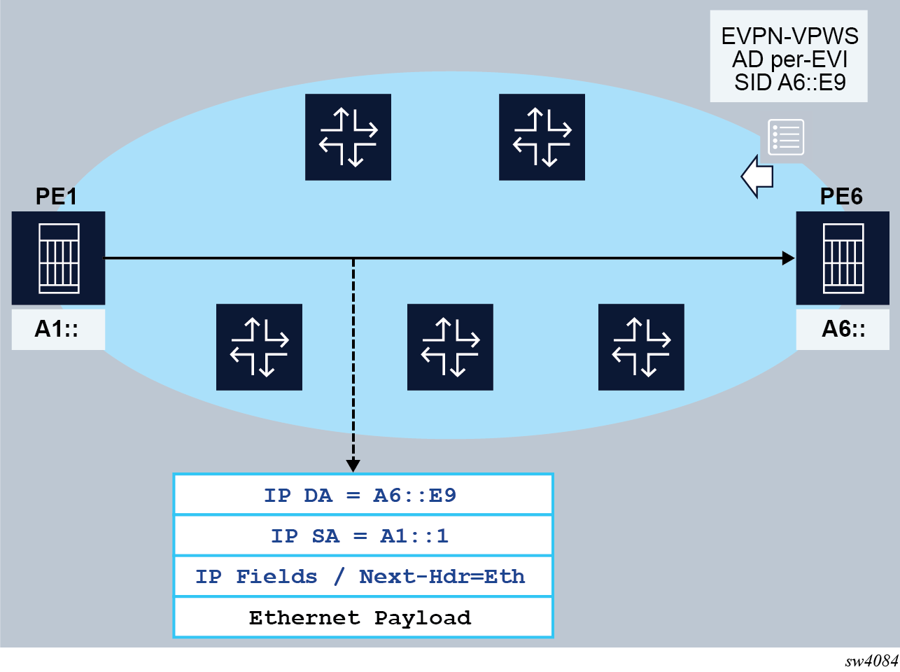
The following figure shows an example for the End.DX2 behavior for EVPN-VPWS services.
The ingress and egress PEs behave as follows:
-
The egress PE (PE6) advertises an A-D per EVI route with the SRv6 service SID that identifies the End.DX2 behavior. The service SID includes the configured locator in the Epipe (A6::), as well as the allocated function (E9) that identifies the Epipe at the egress PE.
-
The ingress PE (PE1) imports the A-D per EVI route and creates an EVPN destination in the corresponding Epipe to A6::E9.
-
When PE1 receives frames at the access SAP, it encapsulates the frames into an SRv6 packet, using the configured IP SA. The IP DA is the EVPN destination SID.
-
Shortest path forwarding is considered in the example shown in End.DX2 behavior for EVPN-VPWS; and therefore, the EVPN destination SID is encoded in the IP DA. If TI-LFA is required, PE1 modifies the encapsulation to include an SRH and additional SIDs.
-
When the SRv6 packet arrives at PE6, the SID encoded in the IP DA identifies the packet for termination on PE6, and the Epipe for decapsulation and forwarding.
Similar procedures are followed for the other required services.
The following table lists the functions that micro-segment SRv6 implements to support the requirements.
| SID function endpoint behavior | Codepoint | SID type: End.SID | SID type: End.X SID | SID type: LAN End.X SID | Advertising protocol | Supported |
|---|---|---|---|---|---|---|
|
uDT6 |
62 |
Yes |
No |
No |
BGP or static |
Yes3
|
|
uDT4 |
63 |
Yes |
No |
No |
BGP or static |
Yes 3 |
|
uDT46 |
64 |
Yes |
No |
No |
BGP or static |
Yes 3 |
|
uDX2 |
65 |
Yes |
No |
No |
BGP or static |
Yes 3 |
|
uDT2U |
67 |
Yes |
No |
No |
BGP or static |
Yes 3 |
|
uDT2M |
68 |
Yes |
No |
No |
BGP or static |
Yes 3 |
BGP extensions
The following BGP extensions are required as per draft-ietf-bess-srv6-services:
-
SRv6 Service TLV:
-
SRv6 Service TLV encoded in the BGP Prefix-SID attribute
-
SRv6 SID Information Sub-TLV (SRv6 Service Sub-TLV type 1) encoded in the SRv6 Service TLV
-
SRv6 SID Structure Sub-Sub-TLV (SRv6 Service Data Sub-Sub-TLV type 1)
-
-
Transposition of 20 bits of the FUNCTION to the Label field of the NLRI
The BGP extensions are applied to the following routes by setting the behavior field in the SRv6 Services TLV is set as per RFC 8986.
-
VPN-IPv4
-
VPN-IPv6
-
IPv4
-
IPv6
-
EVPN AD per-EVI
-
EVPN AD per-ES
Advertising SRv6 service TLVs
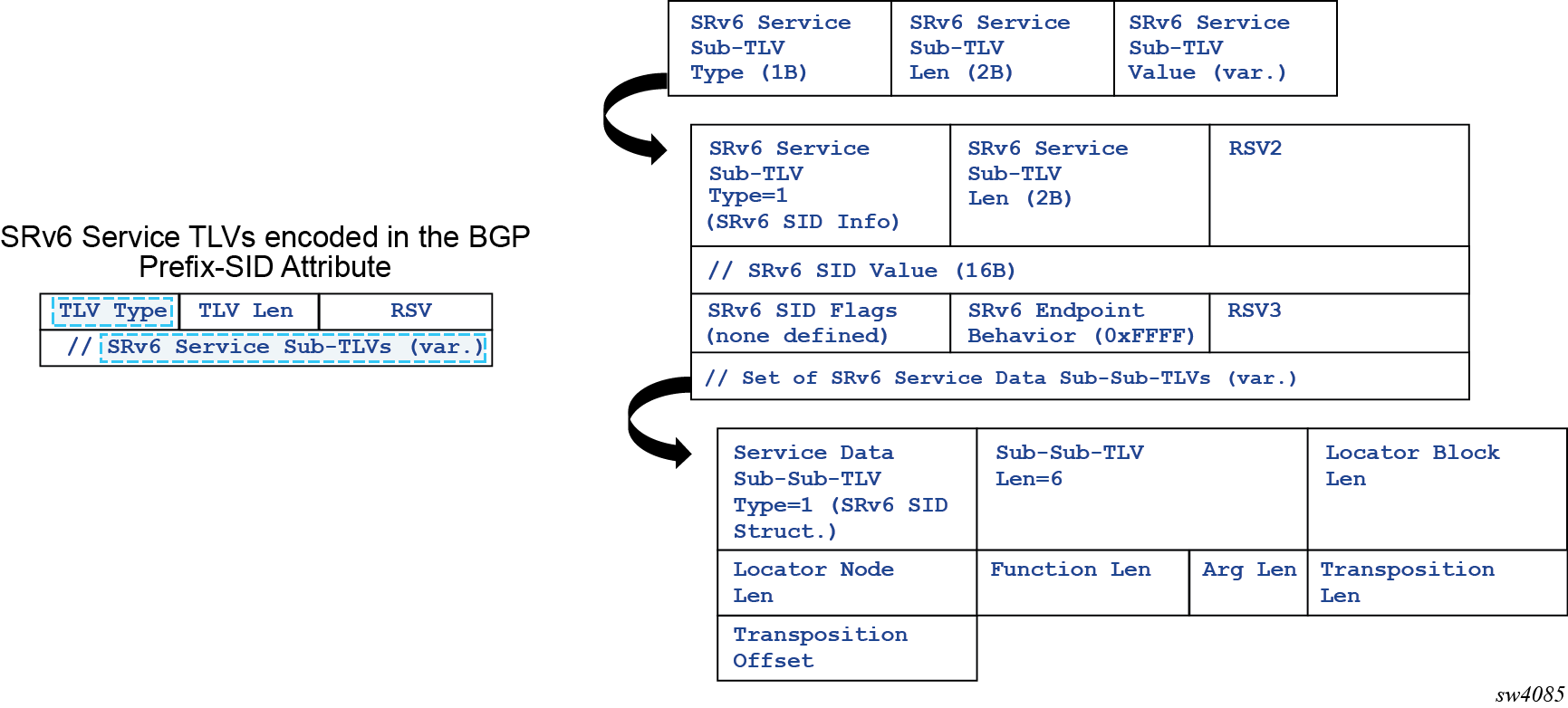
The EVPN, VPN-IPv4, VPN-IPv6, IPv4 and IPv6 routes for the SRv6-enabled services are advertised along with the SRv6 Service TLV. The TLV format is described in draft-ietf-bess-srv6-services and shown in SRv6 service TLV format.
The SRv6 Service TLV encoded in the BGP Prefix-SID attribute can have two different types:
-
Type 5 is used for Layer 3 service SIDs or the SIDs signaled for VPRN services with VPN-IP or EVPN-IFL routes. Layer 3 service SIDs are also supported for the base router along with IPv4/6 routes.
-
Type 6 is used for Layer 2 service SIDs or the SIDs signaled for Epipe or VPLS services. Type 6 is supported along with AD per-EVI and per-ES routes for Epipes.
The SRv6 Service TLV may contain an unordered list of sub-TLVs, but currently the SRv6 Service TLV is advertised with only one sub-TLV – the SRv6 SID Info sub-TLV (type 1). This sub-TLV encodes the following information:
-
For SID value, the entire 128-bit SID allocated to the service. This includes the locator configured for the service and the allocated FUNCTION (which can be dynamically allocated or statically configured on the service). The ARGUMENT is always 0.
-
SID Flags are all zero.
-
Endpoint behavior encodes the behavior as in RFC 8986, in decimal values. The following are relevant for SR OS:
-
18 – End.dt6
-
19 – End.dt4
-
20 – End.dt46
-
21 – End.dx2
-
24 – End.dt2m (only for AD per-ES routes)
-
-
One SID Structure Sub-Sub-TLV (Service Data Sub-Sub-TLV type 1).
The SID Structure Sub-Sub-TLV is always included in routes with label fields and always uses the following values when advertised:
-
Locator Block Length encodes the length of the block configured in the locator for the service.
-
Locator Node Length (the length of the node configured in the locator for the service)
-
Function Length is configurable in the range 20..96.
-
Argument Length is 0.
-
Transposition Length (TL) is 20 for EVPN and VPN-IP routes. For IP routes in the base router, the Transposition Length is always 0.
-
Transposition Offset (TO) for EVPN and VPN-IP routes:
-
If Function Length equals to 20, the Transposition Offset (TO) value equals the prefix length configured in the locator
-
If Function Length is greater than 20, the TO value equals ((prefix length configured in the locator) + (FunctLength -20))
-
-
For IP routes in the base router, the TO value is always 0.
Transposition procedures when advertising service routes
The purpose of the SID Structure Sub-Sub-TLV is twofold:
-
Advertise the structure of the SRv6 SID used in the service, including the length of the locator block, node, function, and argument.
-
Support transposition procedures for efficient service route packing. The FUNCTION is transposed into the label field in the NLRI of the route. Because the rest of the SID is common for routes of the same type in the service, this transposition operation supports efficient packing of routes into the same BGP update.
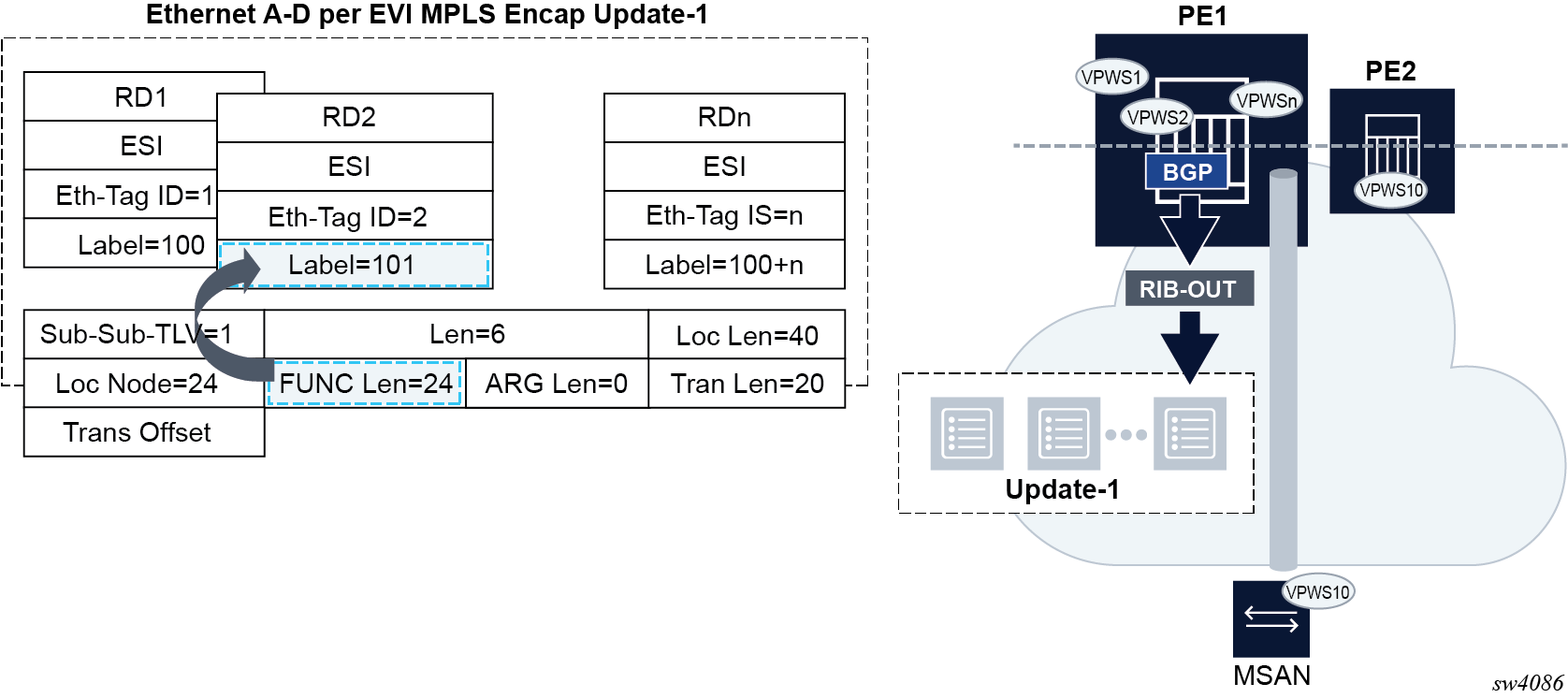
Transposition of the FUNCTION into the NLRI shows how the FUNCTION part of the SID is transposed. The example illustrates how transposition works for EVPN-VPWS, and it is similar for VPN-IP routes.
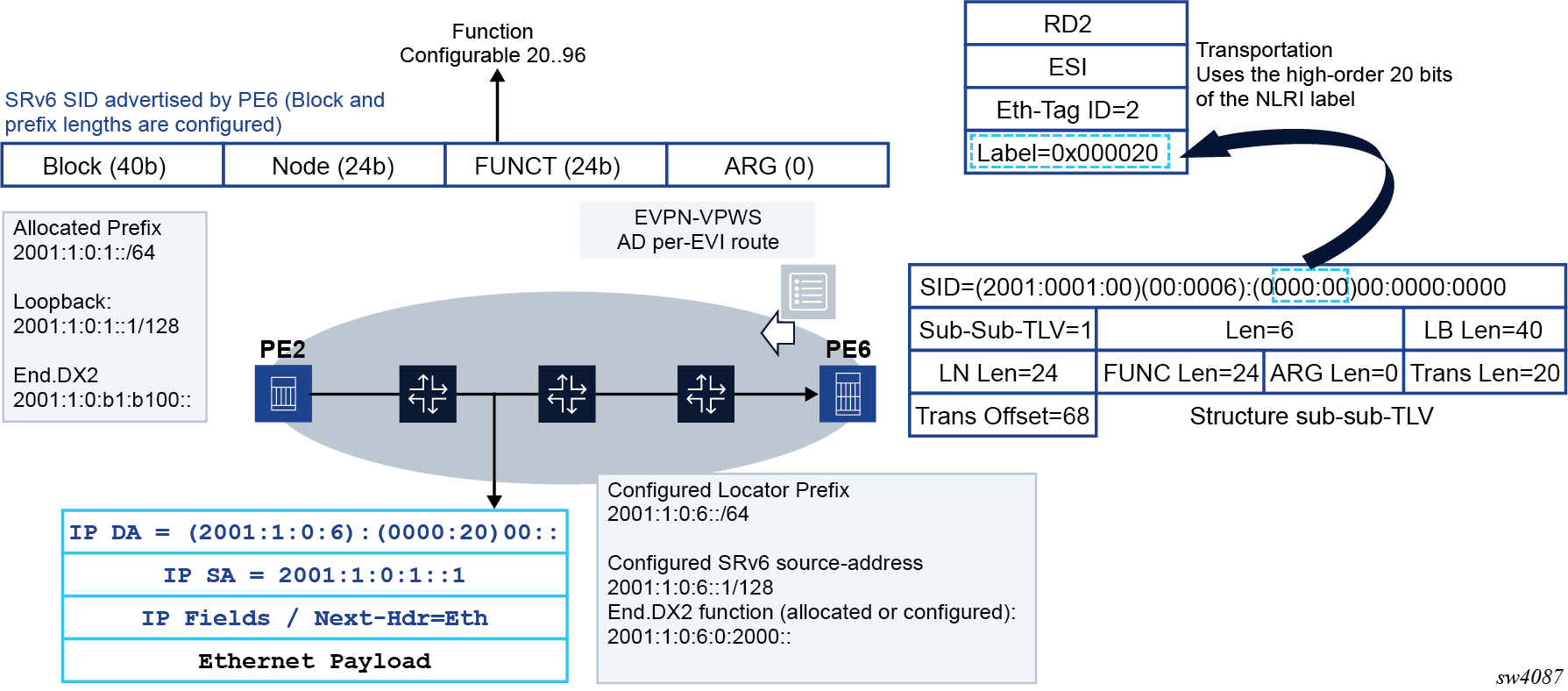
In the Transposition of the FUNCTION into the NLRI example, PE6 is configured with an Epipe that uses a configured locator with LB length = 40 bits and LN length = 24 bits. The FUNC length is set at 24, and 20 bits are always transposed into the NLRI (non-configurable). Based on the example in Transposition of the FUNCTION into the NLRI, the following rules apply:
-
On reception, the router can build any SID out of the received route, regardless of transposition, as long as the lengths are correctly encoded.
-
On transmission, the system performs a transposition for VPN-IP and EVPN service routes as follows:
-
If Function Length is greater than 20 in the Locator configuration, the function bits are put at the right-most bits of the L bits. For example, if LB Len is 40 bits and the LN Len is 24 bits:
-
If Function Length = 20, the entire function is transposed into the label field, and the following is signaled in the route:
Length [LBL, LNL, FL, AL] : [40, 24, 20, 0]
TL:20, TO:64
*A:PE-4>config>router>segment-routing>srv6>locator# info ---------------------------------------------- shutdown block-length 40 termination-fpe 1 prefix ip-prefix cafe:1:0:4::/64 exit static-function max-entries 10 exit ---------------------------------------------- *A:PE-4>config>router>segment-routing>srv6>locator# no shutdown 3 2021/01/19 08:21:16.827 UTC MINOR: DEBUG #2001 Base Peer 1: 2001:db8::3 "Peer 1: 2001:db8::3: UPDATE Peer 1: 2001:db8::3 - Send BGP UPDATE: Withdrawn Length = 0 Total Path Attr Length = 102 Flag: 0x90 Type: 14 Len: 33 Multiprotocol Reachable NLRI: Address Family VPN_IPV4 NextHop len 12 NextHop 192.0.2.4 10.0.0.3/32 RD 192.0.2.4:20 Label 524254 Flag: 0x40 Type: 1 Len: 1 Origin: 0 Flag: 0x40 Type: 2 Len: 0 AS Path: Flag: 0x40 Type: 5 Len: 4 Local Preference: 100 Flag: 0xc0 Type: 16 Len: 8 Extended Community: target:64500:20 Flag: 0xc0 Type: 40 Len: 37 Prefix-SID-attr: SRv6 Services TLV (37 bytes):- Type: SRV6 L3 Service TLV (5) Length: 34 bytes, Reserved: 0x0 SRv6 Service Information Service Information sub-TLV Type 1 Type: 1 Len: 30 Rsvd1: 0x0 SRv6 SID: cafe:1:0:4:: SID Flags: 0x0 Endpoint Behavior: 0x14 Rsvd2: 0x0 SRv6 SID Sub-Sub-TLV Type: 1 Len: 6 BL:40 NL:24 FL:20 AL0 TL:20 TO:64 -
If Function Length = 32, part of the function is transposed into the label field, and the following is signaled in the route:
Length [LBL, LNL, FL, AL] : [40, 24, 20, 0]
TL:20, TO:76*A:PE-4>config>router>segment-routing>srv6>locator# function-length 32 *A:PE-4>config>router>segment-routing>srv6>locator# info ---------------------------------------------- shutdown block-length 40 function-length 32 termination-fpe 1 prefix ip-prefix cafe:1:0:4::/64 exit static-function max-entries 10 exit ---------------------------------------------- *A:PE-4>config>router>segment-routing>srv6>locator# no shutdown 8 2021/01/19 08:27:09.318 UTC MINOR: DEBUG #2001 Base Peer 1: 2001:db8::3 "Peer 1: 2001:db8::3: UPDATE Peer 1: 2001:db8::3 - Send BGP UPDATE: Withdrawn Length = 0 Total Path Attr Length = 102 Flag: 0x90 Type: 14 Len: 33 Multiprotocol Reachable NLRI: Address Family VPN_IPV4 NextHop len 12 NextHop 192.0.2.4 10.0.0.3/32 RD 192.0.2.4:20 Label 524254 Flag: 0x40 Type: 1 Len: 1 Origin: 0 Flag: 0x40 Type: 2 Len: 0 AS Path: Flag: 0x40 Type: 5 Len: 4 Local Preference: 100 Flag: 0xc0 Type: 16 Len: 8 Extended Community: target:64500:20 Flag: 0xc0 Type: 40 Len: 37 Prefix-SID-attr: SRv6 Services TLV (37 bytes):- Type: SRV6 L3 Service TLV (5) Length: 34 bytes, Reserved: 0x0 SRv6 Service Information Service Information sub-TLV Type 1 Type: 1 Len: 30 Rsvd1: 0x0 SRv6 SID: cafe:1:0:4:: SID Flags: 0x0 Endpoint Behavior: 0x14 Rsvd2: 0x0 SRv6 SID Sub-Sub-TLV Type: 1 Len: 6 BL:40 NL:24 FL:32 AL0 TL:20 TO:76
-
-
The label field of the NLRI (VPN-IP and EVPN routes) encodes the FUNCTION that is dynamically or statically allocated for the service.
With the transposition procedure, multiple NLRIs with the same common SRv6 SID (minus the function) can be packed into the same BGP update, as is done for regular VPN-IP or EVPN route for MPLS tunnels. The following figure illustrates the packing benefit.
- The Transposition Length (TL) is always 16 for EVPN and VPN-IP routes.Note: For IP routes in the base router, the TL is always 0.
- Because FL is fixed to 16. the Transposition Offset (TO) = LBL + LNL.
Supported service routes for SRv6
This section lists the service routes that are supported for SRv6.
-
VPRN services configured for SRv6 are as follows:
-
VPN-IPv4 routes
-
VPN-IPv6 routes
-
-
Base router
-
IPv6 routes if configured for SRv6 in IPv6 family
-
IPv4 routes if configured for SRv6 in IPv4 family
-
Epipe services configured for SRv6 are as follows:
-
EVPN AD per-EVI routes
-
EVPN AD per-ES routes, for Epipes that make use of Ethernet Segments
-
-
BGP next hop for SRv6 service routes
As specified in draft-ietf-bess-srv6-services, the egress PE may set the next hop to any of its IPv6 addresses. When the IPv6 address value is not covered by the SRv6 Locator from which the SRv6 Service SID is allocated, the ingress PE performs reachability checks for the SRv6 Service SID in addition to the BGP next-hop reachability procedures.
Next hop and locator resolution considerations:
- On reception of a BGP SRv6 service route, both, locator and next hop are resolved independently in the route table.
- For base instance routes (not Service routes), no ignore-received-srv6-tlvs triggers the independent resolution of the next hop and the locator reachability (and collates their states that drive route programming). The locator state is considered only if the no ignore-received-srv6-tlvs command is configured.
- Whether the router does next-hop-self or next-hop-unchanged does not affect the rib-in processing and reachability (because the next-hop behavior is a rib-out parameter).
- In case a received route has a resolved next hop but unresolved locator, the show router bgp routes commands show ‘valid/best’ but not ‘used’ in the route flags. The command show router bgp next-hop displays the locator and the resolution of the locator:
*A:PE-4# show router bgp next-hop 192.0.2.3 detail vpn-ipv4
===============================================================================
 BGP Router ID:192.0.2.4        AS:64500       Local AS:64500
===============================================================================

===============================================================================
BGP VPN Next Hop
===============================================================================
-------------------------------------------------------------------------------
VPN Next Hop          : 192.0.2.3
Autobind              : gre
Labels                : --
Admin-tag-policy      : --
Strict-tunnel-tagging : N
Color                 : --
Locator               : cafe:1:0:3::/64
-------------------------------------------------------------------------------
Resolving Prefix : 192.0.2.3/32
Preference       : 18                   Metric           : 10
Reference Count  : 6                    Owner            : GRE
Fib Programmed   : Y
Resolved Next Hop: 192.168.34.1
Egress Label     : n/a                  TunnelId         : 4294967293
Locator State    : Resolved
-------------------------------------------------------------------------------
Next Hops : 1
===============================================================================
Route table, FIB table and tunnel table support
The following are the tables and information needed to process a SRv6 packet at service origination, service termination, and transit router roles.
RTM and FIB
SRv6 locator and SID resolution is performed in the RTM and forwarding of all SRv6 packets is performed in the FIB.
The TTM is used to save details of the SRv6 tunnel but is not used directly to forward user or CPM originated packets.
The RTM and FIB are programmed with the routes of the local and remote locators, the local End.X SIDs, and the local End SIDs.
When a policy is applied to export SRv6 routes from RTM to another IS-IS instance, only the IP Reach TLV and the locator TLV, along with the End SID sub-TLVs, are advertised by the receiving IS-IS instance. Local End, End.X, and LAN End.X routes are not exported nor advertised as separate routes.
-
remote locator (route owner = IS-IS)
All routers in the SRv6 domain populate a resolved remote locator prefix received in the SRv6 Locator TLV in the RTM and FIB.
A SRv6 packet is always forwarded out in the datapath using the FIB.
For algorithm 0, the same prefix is advertised with the IP reach prefix TLV and the SRv6 Locator TLV. However, a single route entry is programmed in RTM and FIB.
The prefix of an IGP flexible algorithm locator TLV is never advertised with an IP reach prefix TLV. Therefore, the route of the locator TLV is programmed in RTM and FIB.
-
remote locator with up to 64 ECMP next hops
IS-IS models a remote locator prefix with two or more ECMP next hops as an IGP route with tunneled next hops using a protected NHLFE with hardware PG-ID per tunneled next hop.
This implementation provides uniform failover in ECMP. IS-IS allocates a hardware PG-ID to each next hop it establishes an adjacency with. That PG-ID is then used when programming SRv6 routes of a remote locator and of a local adjacency that resolve to this next hop.
RTM programs the route into the FIB. IS-IS creates a SRv6 tunnel for the locator prefix. The tunnel is added to the TTM. The IS-IS route entries in RTM and FIB point to the tunnel ID of this tunnel in TTM.
Weighted ECMP, when enabled on the interfaces of this IS-IS instance, is supported when forwarding packets over the locator next hops.
-
remote locator with primary or backup next hops
IS-IS models a remote locator prefix with a primary next hop or a primary and LFA backup next hop pair as an IGP route with a tunneled next hop using a protected NHLFE with a hardware PG-ID. This provides uniform failover.
RTM programs the route into the FIB. IS-IS creates a SRv6 tunnel for the locator prefix. The tunnel is added to the TTM. The IS-IS route entries in RTM and FIB point to the tunnel ID of this tunnel in TTM.
-
-
local locator (route owner = SRv6)
All routers in the SRv6 domain populate a route entry in the RTM and FIB to terminate packets destined for the local locator. This is modeled like any other local route but with the SRv6-specific route owner.
-
local adjacency SID (route owner = IS-IS)
All routers in the SRv6 domain populate a route entry in the RTM and regular FIB for each local End.X and LAN End.X adjacency SID with a primary and backup next hops.
The RTM, FIB, and SR module entries are modeled exactly like a remote locator prefix with primary and backup next hops.
-
local End SID (route owner = SRv6)
All routers in the SRv6 domain populate a route entry in the RTM and FIB to terminate packets destined for each local End SID. This is modeled like any other local route but with the SRv6-specific route owner.
With micro-segment SRv6, entries pertaining to local services populate the RTM and FIB. In the FIB, those entries are aggregated. At most, 15 entries are needed to cover the whole service addressing space offered by micro-segment SRv6. The route owner is SRv6.
TTM
The tunnel table is not used directly in the SRv6 locator resolution, in SID resolution, or in packet forwarding. All resolution is performed in the RTM and forwarding is performed in the FIB.
Each resolved remote locator or local adjacency creates an entry in TTM (ROUTE_OWNER_SRV6_ISIS). The entries for remote locators and local adjacencies in the RTM and FIB point to the tunnel ID of this tunnel. The TTM entry is not used directly for forwarding SRv6 packets. However, the route resolution behavior for SRv6 services can be modified to preferentially resolve in TTMv6. See SRv6 policy support for Layer 2 and Layer 3 services for more information.
Users of SRv6 RTM routes
The SRv6 locator and adjacency routes in RTM can be used to forward the following user and CPM originated packets:
-
user packets
-
ICMPv6 echo request and echo reply packets as described in 7450 ESS, 7750 SR, 7950 XRS, and VSR OAM and Diagnostics Guide
-
UDP traceroute packets as described in 7450 ESS, 7750 SR, 7950 XRS, and VSR OAM and Diagnostics Guide
Forwarding and terminating of any other CPM originated packets are not supported. Specifically, received management protocol and control plane protocol packets that are encapsulated in SRv6 are dropped.
If the user configures the address of a BGP neighbor, an LDP peer, or an RSVP-TE LSP destination, to match a locator prefix or a SID, packets are forwarded over the SRv6 tunnel but are dropped at the destination router.
Datapath support
This section describes the details of the packet processing in the datapath on ingress PE, egress PE, and transit P router roles.
SR OS supports both regular SRv6 and micro-segment SRv6. Both modes can operate concurrently on the same platform, but it requires that the SIDs of each type come from different SID blocks.
Service origination and termination roles
The SRv6 processing is performed in a specialized SRv6 FPE. The origination or termination of SRv6 on services require the configuration of a dedicated SRv6 FPE for each; and therefore, the SRv6 origination and termination cannot share the same FPE. A single FPE can be configured for SRv6 origination. One or more FPEs can be configured for SRv6 termination. Transit SRv6 routers do not need SRv6 FPEs.
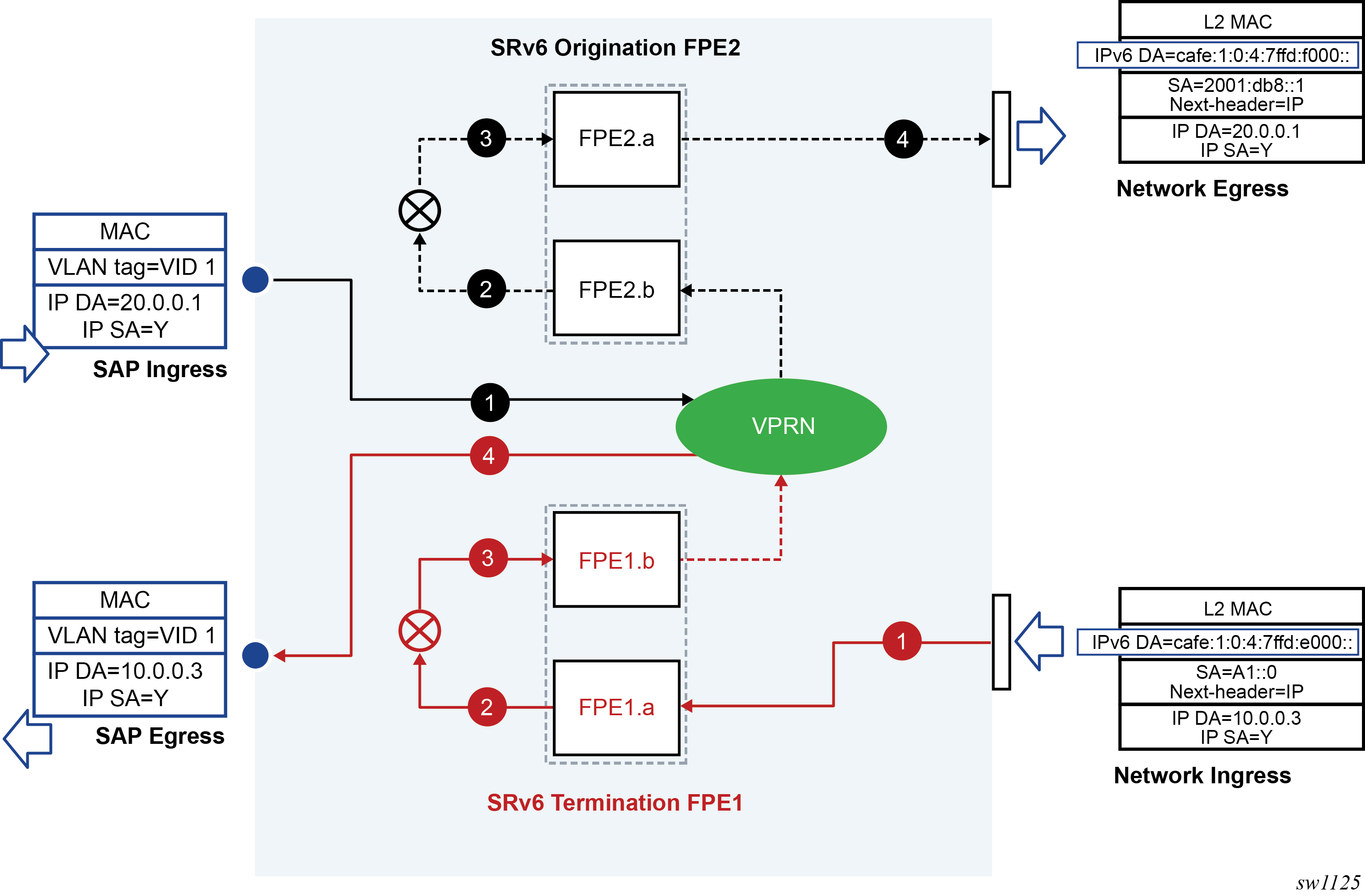
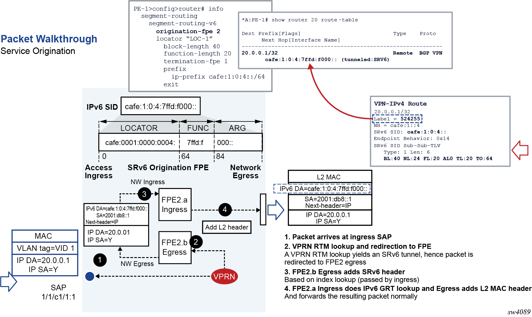
Packet walk-through showing both origination and termination on different SRv6 FPEs shows a couple of SRv6 FPEs that are used to originate and terminate a VPRN service with SRv6 encapsulation.
At the ingress PE
The SRv6 FPE egress datapath receives the L2 or L3 service packet and pushes the SRv6 encapsulation header for the primary path or the backup path.
-
The hop-limit field in the outer IPv6 header of the SRv6 tunnel is set to 255 for all transit IPv4, IPv6, and Ethernet packets encapsulated into SRv6. The hop-limit for OAM packets originated by the CPM on the router is set according to the specific OAM probe. See the 7450 ESS, 7750 SR, 7950 XRS, and VSR OAM and Diagnostics Guide for more details.
-
The SRv6 FPE ingress datapath does the lookup on the outer DA field and forwards the packet to one of the candidate egress network IP interfaces based on the flow label and or SA/DA fields of the outer IPv6 packet header. See Using flow label in load-balancing of IPv6 and SRv6 encapsulated packets for more details on the spraying of SRv6 packets.
The following diagram describes details of the datapath processing of a service packet that is originated on a VPRN with SRv6 encapsulation.
At the egress PE
-
The following procedure is common to the transit router role and the service termination router role.
On the ingress IP network interface, the SRv6 feature concurrently performs two IPv6 address lookups on a received IPv6 packet:- A first (longest prefix match) lookup checks if the address in the outer header DA field matches either the SRv6 local locator subnet, a local End function or local End.X function. This first lookup is for the current SID.
- A second lookup is performed on the next-SID in the SRH (when the IPv6 packet has an SRH). The SRv6 feature reads next-SID using the index value after decrementing the Segments-Left field.
The subsequent processing depends on the outcome of the first lookup:
-
If the match is on the locator only:
-
If the payload type is IPv4, IPv6, or Ethernet, the packet is forwarded to the SRv6 FPE for potential service function processing; see Service origination and termination roles for more details.
The payload type refers to the value of the last next-header field in the processing chain of the packet. This could be the next-header field of the outer IPv6 packet, if there is no SRH. This could also be the next-header field of the active SRH (Segments-Left=1) for which the last SID matches the locator.
-
If the payload type indicates any other protocol, including ICMPv6 (ICMP ping packet) and UDP (potential traceroute message when hop-limit field has a value of 1), the packet is redirected to the CPM for more processing. Protocol matching ICMPv6 ping and UDP traceroute have their packets processed as described in 7450 ESS, 7750 SR, 7950 XRS, and VSR OAM and Diagnostics Guide. Other protocol packets are dropped.
-
-
If the match is on a specific local End function and the next SID lookup is not a local locator, the packet is processed as per the transit router role for these functions as detailed in Transit router role with or without segment termination.
-
If the match is on a specific local End function and the next SID resulted in a match on a local locator, the packet is processed as described in the preceding parent bullet item with the next-header field used in the processing is that of the SRH.
-
If the match is on a specific local End.X function, regardless of the next SID match outcome the packet is processed in accordance with the transit router role for these functions; see Transit router role with or without segment termination.
-
If the match is on a regular IPv6 route or there is no match, the packet is forwarded or dropped. For forwarded packets, the destination address could match the locator prefix or a regular IPv6 prefix of a remote node.
-
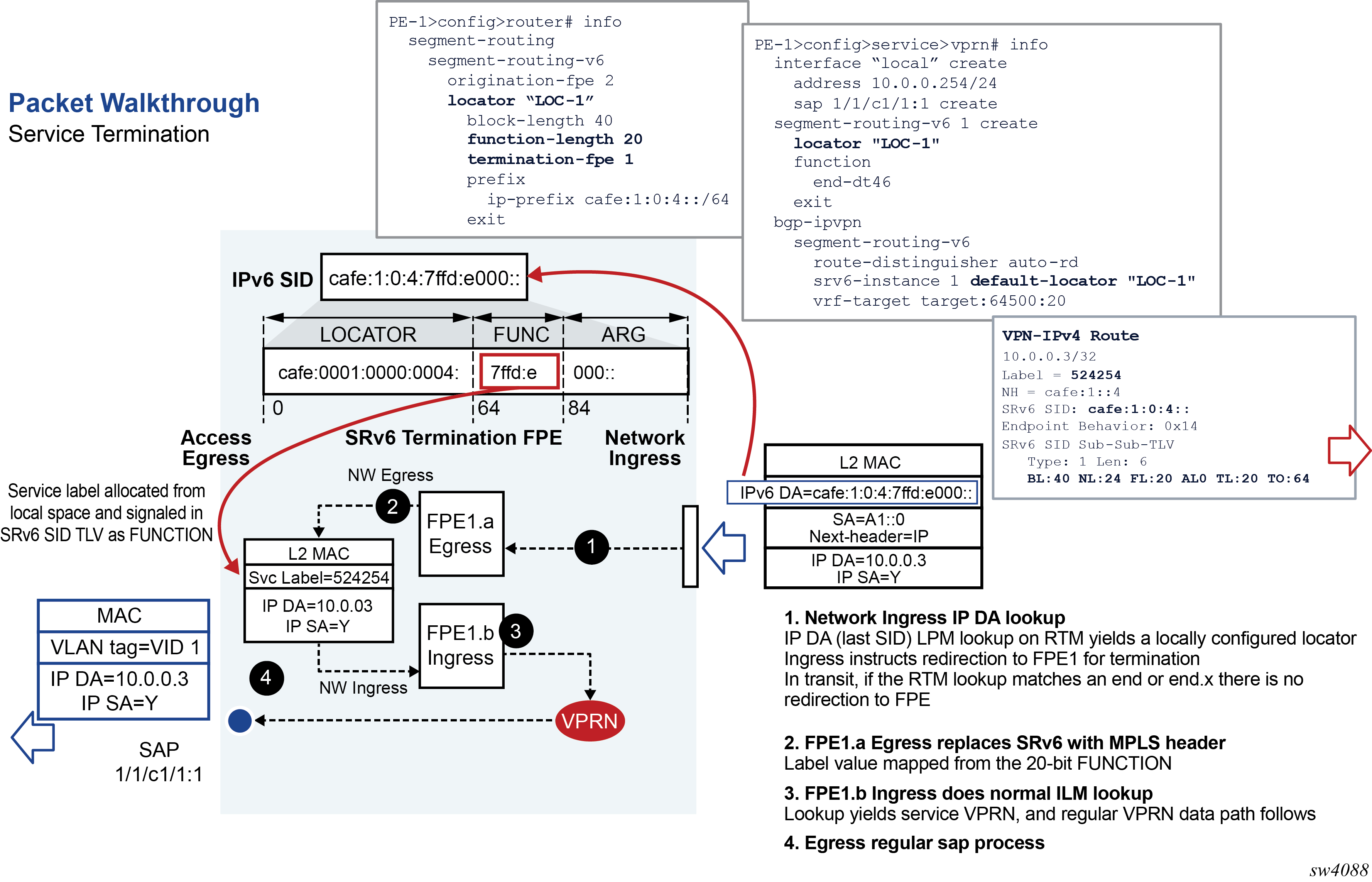
When the match is on the locator entry of the FIB, the egress SRv6 FPE datapath receives the SRv6 encapsulated packet and performs the detailed processing of the specific SID function as per https://tools.ietf.org/html/rfc8986. It then removes the SRv6 encapsulation headers, including SRH if any, and inserts a service label, with the value derived from the FUNCTION field value, into the inner service packet.
-
The egress SRv6 FPE decrements and propagates, into the forwarded inner packet’s IPv4 TTL field or the IPv6 hop-limit field, the minimum of the incoming outer header hop-limit and inner header hop-limit (or TTL) values.
-
The ingress SRv6 FPE does an ILM lookup on the service label and forwards the packet to the service context for further processing.
-
The following diagram describes details of the datapath processing of a service packet that is terminated on a VPRN with SRv6 encapsulation.
Micro-segment SRv6
The datapath behavior for micro-segment SRv6 slightly differs from regular SRv6. The general behavior of performing two lookups applies but the FIB entries are not the same.
After the parallel lookups, the same procedures as for regular SRv6 apply with the following exception. The notion of matching only on a locator does not exist in micro-segment SRv6 because locators also realize an END/uN function. Therefore, a match on a locator is a match on a uN (shift or END). The packet is not sent to the FPE if the first match is on a local locator/uN, but rather if the first match is on a local locator/uN and the second match is on a service SID.
Transit router role with or without segment termination
The transit router role does not require the use of an SRv6 FPE.
The following steps summarize the packet processing for the transit router role. For more information about the specific processing of the SID function see https://tools.ietf.org/html/rfc8986.
-
The procedure in this step is common to a transit router role and the service termination router role.
On the ingress IP network interface, the SRv6 feature concurrently performs a couple of IPv6 address lookups on a received IPv6 packet: a first (longest prefix match) lookup checks if the address in the outer header DA field matches either the SRv6 local locator subnet, a local End function or local End.X function. This first lookup is for the current SID. A second lookup is performed on the next-SID in the SRH when the IPv6 packet has an SRH. The next-SID is read using the index value after decrementing the Segments-Left field.
The subsequent processing depends on the outcome of the first lookup:
-
If the match is on the locator only:
-
If the payload type is IPv4, IPv6, or Ethernet, the packet is forwarded to the SRv6 FPE for potential service function processing. See Service origination and termination roles for further details.
The payload type refers to the value of the last next-header field in the processing chain of the packet. This could be the next-header field of the outer IPv6 packet, if there is no SRH. This could also be the next-header field of the active SRH (Segments-Left=1) which last SID matches the locator.
-
If the payload type indicates any other protocol, including ICMPv6 (ICMP ping packet) and UDP (potential traceroute message when hop-limit field has a value of 1), the packet is redirected to the CPM for further processing.
The CPM processes packets of protocol matching ICMPv6 ping and UDP traceroute; see the 7450 ESS, 7750 SR, 7950 XRS, and VSR OAM and Diagnostics Guide. The CPM drops packets of other protocols.
The CPM generates a specific ICMPv6 message to the address in the SA field of the processed or dropped packet depending on the protocol type and the result of the match of the address in the DA field of the packet. These ICMPv6 reply messages are summarized in ICMPv6 reply messages to extracted SRv6 packets.
Table 9. ICMPv6 reply messages to extracted SRv6 packets Protocol Destination IP address match result ICMPv6 reply (Type/code)
ICMP echo request / reply
(See 7450 ESS, 7750 SR, 7950 XRS, and VSR OAM and Diagnostics Guide for ICMPv6 Ping support in SRv6)
locator prefix [ function | any arg ]
echo reply / ping successful
UDP / TCP
(See 7450 ESS, 7750 SR, 7950 XRS, and VSR OAM and Diagnostics Guide for UDP Traceroute support in SRv6)
locator prefix [ function | any arg ]
dest unreachable, port unreachable
Any other protocol
locator prefix [ function | any arg ]
ICMP Parameter Problem/SR Upper-layer Header Error
All protocols including above
locator prefix | unsupported function
dest unreachable, communication prohibited
-
-
If the match is on a specific local End function and the next SID lookup is not a local locator, the packet is processed as per the transit router role for these functions as described in (2) below.
-
If the match is on a specific local End function and the next SID resulted in a match on a local locator, the packet is processed as per step (1.a) above with the next-header field used in the processing is that of the SRH.
-
If the match is on a specific local End.X function, regardless of next SID match outcome, the packet is processed as per the transit router role for these functions as described in (2) below.
-
If the match is on a regular IPv6 route or there is no match, the packet is forwarded or dropped. If the packet is forwarded, the destination address could match the locator prefix or a regular IPv6 prefix of a remote node.
-
-
If the match is on a local End or End.X SID, the SID termination processing is performed on the packet.
-
If the End or End.X SID is the last SID in the packet encapsulation, meaning there is no SRH or there is only expired SRHs (Segments-Left =0), the packet is sent to the CPM for further processing.
Note: The CPM processes ICMPv6 ping packets and UDP traceroute packets but drops any other protocol type. See the 7450 ESS, 7750 SR, 7950 XRS, and VSR OAM and Diagnostics Guide for more information about the processing of ICPMv6 echo request and reply packets and UPD traceroute packets. -
If the next-header in the IPv6 header is an SRH, the Segments-Left field is zero, and the next-header in the SRH is another SRH, the current SRH is removed and the remaining steps are applied on the next SRH.
-
If the Segments-Left field is 1 and the SRH mode of the terminated SID is PSP, the SRH is removed. Otherwise, the Segments-Left field is decremented and used to read and copy the next SID into the DA field of the outer IPv6 header.
-
Decrement the incoming outer IPv6 header hop-limit and write it into the outgoing packet’s outer IPv6 header hop-limit field.
-
If the first SID lookup of the current SID in the FIB matched an End function, use the outcome of the second SID lookup of the next SID to forward the packet to the next hop of the next SID (in the DA field of the outer IPv6 header).
-
If the first SID lookup of the current SID in the FIB matched an End.X function, override the outcome of the second SID lookup of the next SID with the set of next hops of the adjacency and forward the packet.
-
If both the current and the next SIDs match a local End or End.X SID, the packet is forwarded as indicated in Forwarding behavior for back-to-back local SIDs.
Table 10. Forwarding behavior for back-to-back local SIDs Current SID match Next SID match Forwarding action End
End
Packet is extracted to the CPM which drops it if next SID in not the last SID. An ICMPv6 packet (type: dest unreachable, code: communication prohibited) is sent to the address in the SA field
If the next SID is the last SID, the bounced packet is processed as per ICMPv6 reply messages to extracted SRv6 packets.
End
End.X
Packet is forwarded over the adjacency of next SID to the downstream neighbor which forwards it back to this node for the next SID processing. The bounced packet is forwarded again over the same adjacency.
If the next SID is the last SID, the bounced packet is processed as per ICMPv6 reply messages to extracted SRv6 packets.
End.X
End
Packet is forwarded over the adjacency of the current SID to the downstream neighbor, which forwards it back to the current node for the next SID processing
If the next SID is the last SID, the bounced packet is processed as per ICMPv6 reply messages to extracted SRv6 packets.
End.X
End.X
Packet is forwarded over the adjacency of the current SID to the downstream neighbor, which forwards it back to the current node for the next SID processing
If the next SID is the last SID, the packet is processed as per ICMPv6 reply messages to extracted SRv6 packets.
-
Transit router role in micro-segment SRv6
- The DA field of the IPv6 header contains a single SID (shortest path case).
- Multiple SIDs are used in the DA field and eventually in the SRH (traffic engineering or SR policy).
2001:db8:00d1:d547:: where - <
2001:0db8> is the SID block - <
00d1> is the identifier associated with a specific node - <
d547> is an identifier for a specific local service assigned by the node
2001:0db8><00d1> acts both as a locator
for the specific node and as a uN function. A packet with this address in the DA field
of the IPv6 header is routed toward the specific node with each node along the path
matching on 2001:0db8:00d1::/48 and forwarding to the pre-determined
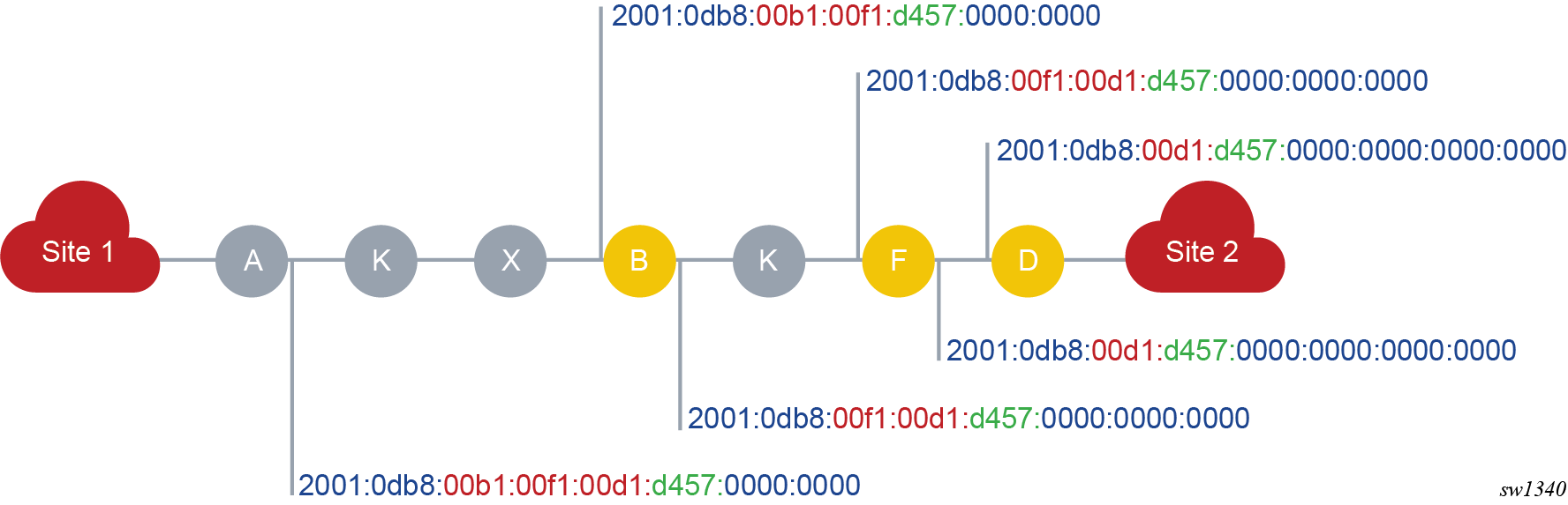
next-hop.Multiple SIDs in the DA field and eventually in the SRH illustrate the following micro-segment SRv6 behavior.
- The micro-SID block is
2001:0db8::/32. - The node identifiers (uN) are
0x00b1for node B,0x00f1for node F, and0x00d1for node D. - Node D has advertised
2001:0db8:00d1:d457::for the specific service.
- It constructs the following container:
2001:0db8:00b1:00f1:00d1:d457:: - It places this container in the DA field of the IPv6 header.
- It forwards the packet to the next-hop determined by an LPM on that address.
Transit routers in micro-segment SRv6 illustrates the above example.
2001:0db8:00b1::/48 (as it has that entry in its FIB)
and performs the operation associated with that micro-SID:- It removes the 16-bit from the address.
- It shifts the right part toward the MSB.
- It adds a 16-bit block of zeros, the so called End of Container (EoC), as the LSB
Node F does the same (based on matching on its own identifier).
Node D does the same but processes the packet in the service corresponding to the identifier.
It can be that the path is longer than the number of micro-SIDs that can be compressed in 128 bits. In that case, an SRH is used to convey the rest of the path. Each container in the SRH must be of the same form (a block part followed by a sequence of micro-SIDs). At some node along the path, because of the shift operations, the container in the IPv6 DA expires. At that node, micro-segment SRv6 implements a regular SRv6 END function (or END.X function if the match is on a uA).
For example, if node B receives a packet with 2001:0db8:00b1:: in the DA
field, it detects that its own identifier is followed by an EoC. Node B copies the next
segment or container from the SRH in the DA field.
Using flow label in load-balancing of IPv6 and SRv6 encapsulated packets
When a service is bound to an SRv6 tunnel, the service packets are first forwarded to the egress network interface of the SRv6 origination FPE to build and push the SRv6 encapsulation. The packets are then handed in to the ingress network interface of the SRv6 origination FPE which sprays the packets over the ECMP next hops of the SRv6 tunnel and LAG links of the outgoing network interfaces.
The default hash calculation on the ingress service SAP or interface is based on the existing hash procedures of an IPv4, IPv6, or an Ethernet packet. For IPv6 service packets, an option is provided to include the packet’s Flow Label field, when not zero, and to hash on the triplet {SA, DA, Flow Label}. The flow-label-load-balancing command is used to enable this behavior on an access or network interface.
The SRv6 origination FPE egress network interface copies the output of the hash on the inner packet headers into the flow label field of the outer IPv6 header that it pushes on the SRv6 encapsulated packet. This is regardless of whether the flow label is used or not in the computation of the hash on the service packet.
The SRv6 origination FPE ingress network interface does not require the flow-label-load-balancing command to be enabled. All SRv6 packets are automatically sprayed to the ECMP next hops of the SRv6 tunnel and LAG links of the outgoing network interfaces using a hash on the triplet {SA, DA, Flow Label} in the SRv6 packet’s outer IPv6 header.
On a transit router, the hashing of SRv6 encapsulated packets can also use the Flow Label field in the outer IPv6 header to provide more entropy to the load-balancing process of SRv6 packets. The flow-label-load-balancing command can be configured on a network interface to hash on the triplet {SA, DA, Flow Label}. By default, a transit router only hashes on the tuple {SA, DA} in the header of a received IPv6 packet with a non-zero flow label field, including when the packet is SRv6. The description of the flow-label-load-balancing command and the detailed behavior of the hash feature based on the IPv6 packet flow label field and its general application to access and network interfaces is described in section IPv6 Flow Label Load Balancing of the 7450 ESS, 7750 SR, 7950 XRS, and VSR Interface Configuration Guide.
Interaction with other datapath features
The following describes the interaction of the SRv6 feature with other datapath features.
-
When SRv6 is enabled on the base router, datapath enables forwarding and receiving SRv6 encapsulated packets on all network interfaces of the router. The datapath, however, drops an SRv6 encapsulated packet if received from or needs forwarding to an access interface (IES, VPRN). A service packet received on either a network interface or an access interface can be encapsulated into a SRv6 packet and forwarded to a network interface.
-
SRv6 feature performs concurrently a couple of IPv6 address lookups on a packet received with an SRH. The first lookup is for the current SID in the DA field in the header of the received SRv6 packet and the second is for the next SID in the SRH.
The datapath repurposes the IPv6 unicast RPF (IPv6 uRPF) check for the next SID lookup, which means the IPv6 uRPF feature cannot be performed on all IPv6 packets received on that interface. CLI enforces this interaction and so SRv6 cannot be enabled in the base router context (config>router>segment-routing>segment-routing-v6) if the IPv6 uPRF check (config>router>if>ipv6>urpf) is enabled on one or more network interfaces.
Conversely, the IPv6 uRPF check cannot be enabled on a network interface if SRv6 is enabled in the base router context.
Note: SRv6 does not impact uRPF checks of IPv4 packets received on a network interface. -
When SRv6 is enabled in one or more IGP instances, a transit router cannot check the SA field in the outer IPv6 header of a SRv6 encapsulated packet received on a network interface and that also has an SRH header. Normally an IPv6 packet which uses 0::0 or a link-local address format should be dropped. All other IPv6 packets, including a SRv6 encapsulated packet that does not have an SRH header, are checked for these two situations.
-
Policy Based Routing (PBR) is allowed on flows of packets of an SRv6 tunnel. In other words, the user can apply an ACL filter on a network interface which matches on the outer SA and DA fields of the SRv6 packet and execute an action such as a redirection.
The operator must ensure that SRv6 matching packets are directed to a router that can process and forward the SRv6 packets.Note: Redirecting an SRv6 packet even to an SRv6-capable router is not recommended because the processing of the SID list in the SRH can create loops for any of the SIDs in the outer DA and SRH.
LFA support
LFA, remote LFA, and TI-LFA are supported in the following router roles:
-
service originating role
-
transit role with segment termination
-
transit role without segment termination
The backup is computed and programmed for each remote SRv6 End SID, service SID (End.DT4, End.DT6, End.DT46, and End.DX2), as well as for each local End.X or LAN End.X SID.
A base LFA backup path or a TI-LFA backup path that uses a direct IP next hop (not a repair tunnel), requires configuring a next hop that is different from the primary path and does not modify the SID list pushed on the primary path.
When the Remote LFA or TI-LFA backup path uses a repair tunnel (source routed or not), the additional SIDs of the repair tunnel must be inserted into the packet when the backup is activated. This requires the insertion of a LFA dedicated SRH into the packet. The SRV6 behavior is referred to as H.Insert.Red and is described in https://tools.ietf.org/html/draft-filsfils-spring-srv6-net-pgm-insertion-04. The application of this behavior to the LFA repair tunnel is described in https://tools.ietf.org/html/draft-voyer-6man-extension-header-insertion-10.
LFA repair tunnel packet encoding illustrates the packet encoding for the primary and remote LFA backup path using a dedicated reduced SRH for the repair tunnel.
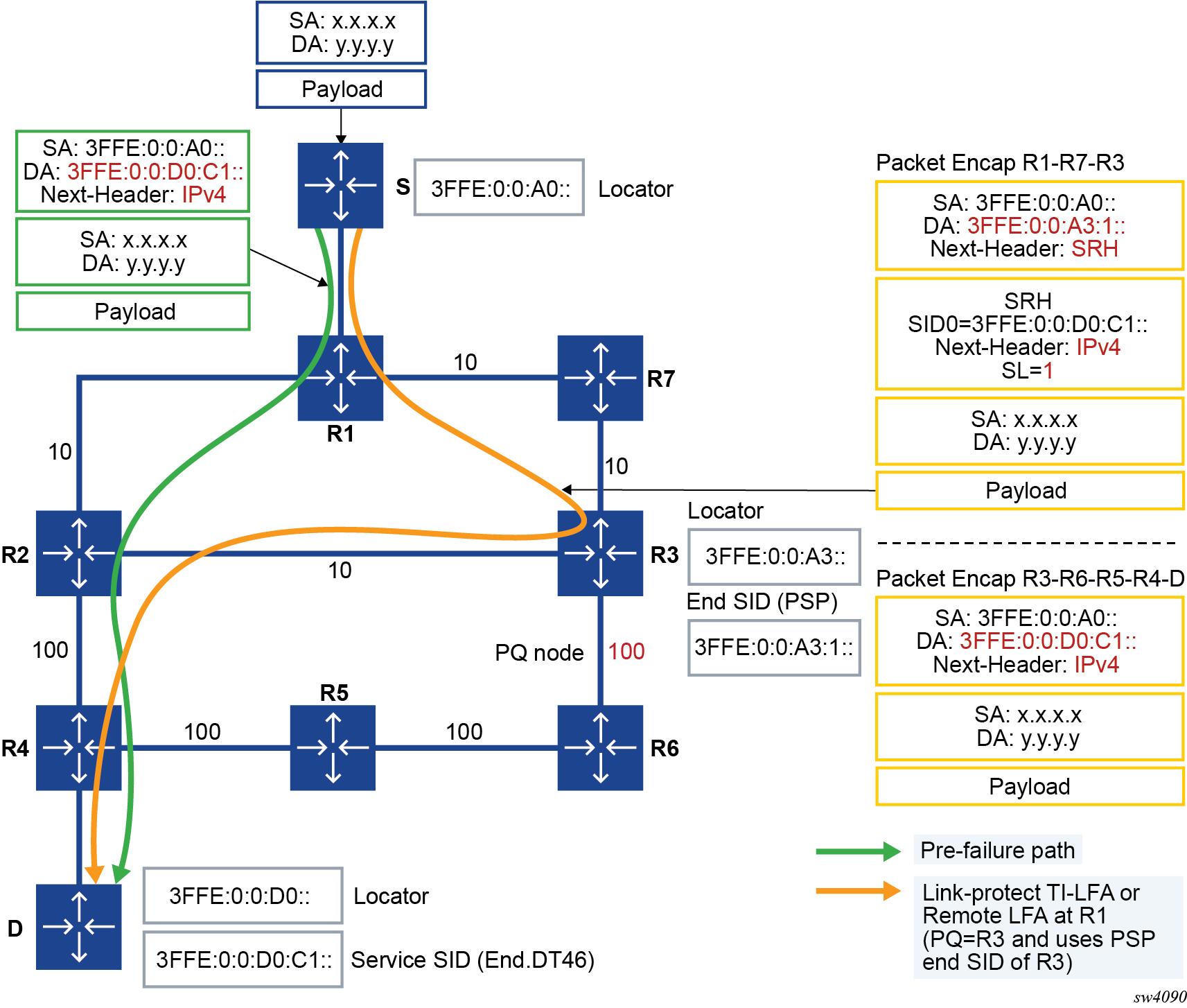
The LFA backup path for the prefix of a remote End SID, and of a remote service SID is programmed in RTM and in the FIB with the entry of the prefix of the locator of that SID. This is because forwarding to these SIDs is based on looking up the remote locator they were derived from.
The LFA backup for a local End.X or a local LAN End.X is programmed in RTM and the FIB with the specific entry corresponding to this SID.
When the LFA backup is a direct IP link, the encapsulation of the packet is not changed. The packet is forwarded out of the backup path next hop interface.
When the LFA backup is a tunnel, the SRv6 feature can insert one additional SID for an RLFA or TI-LFA PQ node. This provides sufficient coverage in the following repair tunnel cases:
-
The TI-LFA backup is a direct neighbor and the packet is forwarded on the backup outgoing interface with no additional SIDs.
-
The P and Q nodes are the same node if it is a neighbor of the computing node or not. An End SID of the PQ node is inserted into the SID list.
-
The P and Q nodes are connected using a single adjacency with the P node a neighbor of the computing node or not. An End.X SID of the P-Q adjacency is inserted into the SID list. Because an End.X adjacency SID is taken from a locator globally routable prefix, this case requires a single SID instead of a couple of SIDs with SR-MPLS.
IS-IS procedures
The base LFA, remote LFA, and TI-LFA features operate on an SRv6 tunnel the same way as on SR-MPLS tunnels.
- MD-CLI
configure router isis loopfree-alternate - classic
CLI
configure router isis loopfree-alternates
- MD-CLI
configure router isis loopfree-alternate remote-lfa configure router isis loopfree-alternate ti-lfa - classic
CLI
configure router isis loopfree-alternates remote-lfa
configure router isis loopfree-alternates ti-lfa
In SRv6, the max-srv6-frr-sids value controls the maximum number of SRv6 SIDs that can form a backup path.
With regular SIDs, any configured value greater than one is not considered and the effective value is one. With micro-SIDs, the effective value is the configured one.
- A (uN, uA) pair of micro-SIDs is counted as one SID if both belong to the same node.
- When borrowing the backup path of the SID of the neighbor node (uN) to protect an adjacency SID (uA) to that neighbor, SR OS allows the uN SID of the neighbor node on the other side of the adjacency in excess of the max-srv6-frr-sids value if it does not result in additional overhead (one container limit).
The TI-LFA algorithm prefers a micro-segment locator over a regular locator in case both exist. As such, a micro-segment path may protect a regular SRv6 path.
The following is a description of the SRv6-ISIS tunnel backup path computation. A reduction of the segment list is applied to minimize the SID list of the computed backup path.
When two or more End.X SIDs of the same SRH processing type exist, IS-IS prefers the SID with protection enabled and selects the SID with lowest function value from the protected or unprotected SID subset.
The backup path of a remote locator is as follows:
-
TI-LFA
IS-IS adds the End.X SID of the P-Q set adjacency to the repair tunnel. The datapath encodes this SID into the DA field of the outer IPv6 header and moves the received value in the DA field into the LFA SRH. The protected locator prefix backup next hop in the RTM points to the tunnel ID of the locator prefix of the P-Q set adjacency.
-
base LFA
If an alternate equal-cost parallel link exists to the LFA neighbor, IS-IS programs it as a regular IP next hop of the protected locator.
If the alternate parallel link to the LFA neighbor is not equal-cost, IS-IS programs a null SID repair tunnel. The datapath does not push an LFA SRH in this case. The protected locator prefix backup next hop in the RTM points to the tunnel ID of the local adjacency over the outgoing link to the LFA neighbor.
-
remote LFA
IS-IS adds the End SID of the PQ node to the repair tunnel. The datapath encodes this SID into the DA field of the outer IPv6 header and moves the received value of the DA field into the LFA SRH. The protected locator prefix backup next hop in the RTM points to the tunnel ID of the locator prefix of the PQ node.
Note: If P node is a neighbor of the computing node, the SID list is empty and the backup next hop of the protected locator prefix in the RTM points to the tunnel ID of the local adjacency over the outgoing link to the LFA neighbor.
The backup path of a local adjacency is as follows:
-
TI-LFA
IS-IS computes the repair tunnel by using the End.X SID of the adjacency between the P and Q nodes, plus an End SID of the neighbor node on the other side of the protected adjacency. This repair tunnel is programmed after reducing the segment list to the adjacency SID of the link between the P node and the neighbor node, only if the Q node is the same as the neighbor node on the other side of the protected adjacency. The datapath encodes that adjacency SID into the DA field of the outer IPv6 header and moves the received value of the DA field into the LFA SRH.
-
base LFA
IS-IS attempts first to program a null SID repair tunnel by using the adjacency of an alternate parallel link to the neighbor on the other side of the protected adjacency. The datapath does not push an LFA SRH in this case. The protected locator prefix backup next hop in the RTM points to the tunnel ID of the local adjacency over the outgoing link to the LFA neighbor.
If the first option fails, IS-IS programs a repair tunnel by using the End SID of the neighbor on the other side of the protected adjacency. The datapath encodes that End SID of the neighbor into the DA field of the outer IPv6 header and moves the received value of the DA field into the LFA SRH.
-
remote LFA
IS-IS computes the repair tunnel by using the End SID of the PQ node and an End SID of the neighbor node on the other side of the protected adjacency. This repair tunnel is programmed after reducing the segment list to the adjacency SID of the link between the PQ node and the neighbor node, only if the PQ node is one hop from the node on the other side of the protected adjacency. The datapath encodes that adjacency SID into the DA field of the outer IPv6 header and moves the received value of the DA field into the LFA SRH.
-
End 0x01
-
End_PSP 0x02
-
End_USP 0x03
-
End_PSP_USP 0x04
When two or more End SIDs of the same SRH processing type exist, IS-IS selects the SID with the lowest function value.
Datapath procedures
The datapath procedures for the service origination router role, as described in Service origination and termination roles, are modified as follows when the LFA backup is a repair tunnel.
-
The top SID of the primary path is copied into the LFA SRH as the only SID in the SID list. The Segments-Left field of the LFA SRH is set to 1.
-
The End SID of the PQ node or the End.X SID of the P-Q adjacency is copied in the DA field of the outer IPv6 header.
-
If the PQ node is the same as the node that owns the top SID of the primary path, the LFA SRH insertion must be skipped. This is not a datapath procedure per se, but IGP reduces the segment list of the backup path to look the same as that of the primary path.
The datapath procedures for the transit router role, as described in Transit router role with or without segment termination, are modified as follows when the LFA backup is a repair tunnel.
-
The next SID, read from the original SRH after decrementing the Segments-Left field, or from the DA field if no SRH exists, is copied into the LFA SRH as the only SID in the SID list. The Segments-Left field of the LFA SRH is set to 1.
-
The SID of the PQ node is copied in the DA field of the outer IPv6 header.
-
If the PQ node is the same as the node that owns the next SID, the LFA SRH insertion must be skipped. This is not a datapath procedure per se, but IGP reduces the segment list of the backup path to look the same as that of the primary path.
SRv6 tunnel metric and MTU settings
IGP sets the metric of the SRv6 remote locator prefix route or that of a local adjacency SID route to the metric of the computed path of the corresponding route.
The metric of a local End SID route is set to 0; similar to any local route.
The metric of a BGP IPv4/IPv6 or VPN-IPv4/VPN-IPv6 route resolved to a SRv6 tunnel inherits the value of the locator prefix route metric.
The user should configure the network interfaces at the ingress PE and at transit P routers with an MTU value that accounts for the fixed IPv6 header (40 bytes) and the additional LFA SRHs (24 bytes each).
The SRv6 origination FPE interface (interface-b) at ingress PE requires special attention. The datapath accounts for the fixed 40-byte IPv6 header when checking for fragmenting IPv4 packets (DF=0) or dropping IPv4 (DF=1) and IPv6 packets that are intended to be forwarded over an SRv6 tunnel. If LFA is enabled in IS-IS, the LFA overhead is not accounted for, and therefore the configured MTU for the SRv6 origination FPE interface must account for it.
In addition, there are network deployments where it is not possible to modify the network interface MTU or to set all network interfaces to the same value. In that case, the user must configure the SRv6 origination FPE interface MTU to reflect this worst case MTU in the network, accounting fixed and variable LFA overhead. The following is the CLI to use for this purpose.
configure
+--fwd-path-ext
   +--fpe <fpe-id> [create]
         +--srv6 <origination | termination>
            +--interface-b
                +--mtu <1280-9786>
The show router base icmp6 command has a global count for received “Packets Too Big” that captures the dropped packets on network interfaces, including SRv6 origination FPE interface, caused by MTU violation.
MTU configuration examples
The following are examples of MTU settings of the SRv6 origination FPE interface (interface-b).
-
all default values
By default, LFA is disabled in IS-IS. The network interface default MTU is 9786 bytes based on default Ethernet MTU of 9800 bytes.
The SRv6 origination FPE interface MTU defaults to the same value of 9786 bytes; there is no need for further adjustments.
-
all default values and RLFA or TI-LFA enabled
The user must adjust the SRv6 origination FPE interface MTU from the first bullet item case to account for the 24 bytes introduced by LFA.
SRv6 origination FPE Interface MTU is 9786 - 24 = 9762 bytes.
-
a remote constrained network interface and RLFA or TI-LFA enabled
Assume a specific remote network interface in the SRv6 network is limited to a maximum value of 1500 bytes. The user must adjust the SRv6 origination FPE interface MTU in all the ingress PEs from the first bullet item case, to account for that constrained value, plus the 24 bytes introduced by LFA repair tunnel (Users can adjust for as many LFA SRHs as they need. The following example assumes 1 LFA SRH).
SRv6 origination FPE Interface MTU = 1500 - 24 = 1476 bytes.
Service extensions
This section describes the extensions for the origination and termination of SRv6 services.
The extensions also apply to micro-segment SRv6. To distinguish a regular locator from a micro-segment locator, specific CLI contexts, matching those for regular SRv6, are available .
SRv6 forwarding path extension
The SRv6 FPE type is required for the termination and origination of SRv6 services. The following guidelines apply for the SRv6 FPE:
-
An internal or external Port Cross-Connect (PXC) can be used for the SRv6 FPE.
-
The SRv6 origination or termination FPE cannot be shared with other applications, but the same physical ports can be used when configuring PXC ports for multiple FPEs of different applications.
As an example of how two FPEs can share the same physical port (therefore the same bandwidth), define two PXC ports, both sharing the same underlaying physical port; for instance:
FPE 1 is associated with PXC-1 and FPE 2 is associated with PXC-2, where PXC-1 and PXC-2 are both assigned to port 1/1/1
-
Some considerations about the SRv6 termination FPE follow:
-
It is configured per locator.
-
Multiple locators can optionally use the same or different FPE.
-
Received SRv6 traffic for a specific (local) locator is redirected to the SRv6 termination FPE interface-a.
-
-
Some considerations about the SRv6 origination FPE follow:
-
There is only one SRv6 origination FPE supported per system.
-
The SRv6 origination and termination FPEs are always different.
-
-
SRv6 FPE redundancy and load-balancing:
-
Each FPE can use a LAG composed of as many PXC ports as needed (there is no specific limitation in the number of PXC members per LAG).
-
LAG members can be PXC ports in the same or a different card.
-
The following CLI is required to create the FPE of type srv6 origination or termination and apply it to a locator. All locators may be associated with the same or a different FPE.
configure
+--fwd-path-ext
   +--fpe <fpe-id>
      +--application
         +--srv6 <origination|termination>
            +--interface-a
               +--qos <network-policy-id>
            +--interface-b
               +--mtu <1280-9786>
               +--qos <network-policy-id>
configure
+--router
|    +--segment-routing
|    |    +--segment-routing-v6
|    |    |    +--origination-fpe <fpe>
|    |    |    +--source-address <ipv6-address>
|    |    |    +--locator <locator-name>
|    |    |    |    +--termination-fpe <fpe>
SRv6 VPRN services
VPRN services support SRv6 End.DT4, End.DT6, and End.DT46 behaviors. VPRNs support IPv4 and IPv6 routes that are advertised in VPN-IPv4 and VPN-IPv6 families, as well as in EVPN IP Prefix routes in Interface-less mode (EVPN-IFL).
The following classic CLI configures a VPRN for SRv6 with the VPN-IP families.
configure
+--service
|   +---vprn <service-id>
|   |   +---segment-routing-v6 <instance-id>
|   |   |   +---locator <locator-name>
|   |   |   |   +---function
|   |   |   |   |   +---end-dt4 <integer>
|   |   |   |   |   +---end-dt6 <integer>
|   |   |   |   |   +---end-dt46 <integer>
|   |   +---bgp-ipvpn
|   |   |   +---segment-routing-v6 <bgp-instance-id>
|   |   |   |   +---srv6-instance <id> default-locator <name>
|   |   |   |   +---source-address <ipv6-address>
|   |   |   |   +---route-distinguisher <rd>
|   |   |   |   +---vrf-export
|   |   |   |   +---vrf-import
|   |   |   |   +---vrf-target
|   |   |   |   +---default-route-tag <number>
|   |   |   |   +---shutdown
The following MD-CLI configures a VPRN for SRv6 with the VPN-IP families.
configure
+--service
|   +---vprn <service-id>
|   |   +-- segment-routing-v6 <number>
|   |   |   +-- apply-groups <reference>
|   |   |   +-- apply-groups-exclude <reference>
|   |   |   +-- locator <reference>
|   |   |       +-- apply-groups <reference>
|   |   |       +-- apply-groups-exclude <reference>
|   |   |       +-- function
|   |   |           +-- end-dt4
|   |   |           |   +-- value <number>
|   |   |           +-- end-dt46
|   |   |           |   +-- value <number>
|   |   |           +-- end-dt6
|   |   |           |   +-- value <number>
|   |   +---bgp-ipvpn
|   |   |   +-- segment-routing-v6 <number>
|   |   |       +-- admin-state <keyword>
|   |   |       +-- apply-groups <reference>
|   |   |       +-- apply-groups-exclude <reference>
|   |   |       +-- default-route-tag <number>
|   |   |       +-- domain-id <string>
|   |   |       +-- evi <number>
|   |   |       +-- resolution <keyword>
|   |   |       +-- route-distinguisher <string | keyword>
|   |   |       +-- source-address <global-unicast-ipv6-address>
|   |   |       +-- srv6
|   |   |       |   +-- default-locator <reference>
|   |   |       |   +-- instance <reference>
|   |   |       +-- vrf-export
|   |   |       |   +-- apply-groups <reference>
|   |   |       |   +-- apply-groups-exclude <reference>
|   |   |       |   +-- policy <string | reference>
|   |   |       +-- vrf-import
|   |   |       |   +-- apply-groups <reference>
|   |   |       |   +-- apply-groups-exclude <reference>
|   |   |       |   +-- policy <string | reference>
|   |   |       +-- vrf-target
|   |   |           +-- community <string>
|   |   |           +-- export-community <string>
|   |   |           +-- import-community <string>
The following classic CLI configures a VPRN for SRv6 with EVPN-IFL.
configure
+--service
|   +---vprn <service-id>
|   |   +-- segment-routing-v6 <number>
|   |   |   +-- apply-groups <reference>
|   |   |   +-- apply-groups-exclude <reference>
|   |   |   +-- locator <reference>
|   |   |       +-- apply-groups <reference>
|   |   |       +-- apply-groups-exclude <reference>
|   |   |       +-- function
|   |   |           +-- end-dt4
|   |   |           |   +-- value <number>
|   |   |           +-- end-dt46
|   |   |           |   +-- value <number>
|   |   |           +-- end-dt6
|   |   |           |   +-- value <number>
|   |   +---bgp-evpn
|   |   |   +---segment-routing-v6 <bgp-instance-id>
|   |   |   |   +---srv6-instance <id> default-locator <name>
|   |   |   |   +---source-address <ipv6-address>
|   |   |   |   +---route-distinguisher <rd>
|   |   |   |   +---vrf-export
|   |   |   |   +---vrf-import
|   |   |   |   +---vrf-target
|   |   |   |   +---default-route-tag <number>
|   |   |   |   +---shutdown
The following MD-CLI configures a VPRN for SRv6 with EVPN-IFL.
configure
+--service
|   +---vprn <service-id>
|   |   +-- segment-routing-v6 <number>
|   |   |   +-- apply-groups <reference>
|   |   |   +-- apply-groups-exclude <reference>
|   |   |   +-- locator <reference>
|   |   |       +-- apply-groups <reference>
|   |   |       +-- apply-groups-exclude <reference>
|   |   |       +-- function
|   |   |           +-- end-dt4
|   |   |           |   +-- value <number>
|   |   |           +-- end-dt46
|   |   |           |   +-- value <number>
|   |   |           +-- end-dt6
|   |   |           |   +-- value <number>
|   |   +---bgp-evpn
|   |   |   +-- segment-routing-v6 <number>
|   |   |       +-- admin-state <keyword>
|   |   |       +-- apply-groups <reference>
|   |   |       +-- apply-groups-exclude <reference>
|   |   |       +-- default-route-tag <number>
|   |   |       +-- domain-id <string>
|   |   |       +-- evi <number>
|   |   |       +-- resolution <keyword>
|   |   |       +-- route-distinguisher <string | keyword>
|   |   |       +-- source-address <global-unicast-ipv6-address>
|   |   |       +-- srv6
|   |   |       |   +-- default-locator <reference>
|   |   |       |   +-- instance <reference>
|   |   |       +-- vrf-export
|   |   |       |   +-- apply-groups <reference>
|   |   |       |   +-- apply-groups-exclude <reference>
|   |   |       |   +-- policy <string | reference>
|   |   |       +-- vrf-import
|   |   |       |   +-- apply-groups <reference>
|   |   |       |   +-- apply-groups-exclude <reference>
|   |   |       |   +-- policy <string | reference>
|   |   |       +-- vrf-target
|   |   |           +-- community <string>
|   |   |           +-- export-community <string>
|   |   |           +-- import-community <string>
The associated locator must be configured to enable SRv6 on the VPRN service. In addition, the following rules apply:
-
The function value can be statically configured, or it is dynamically allocated.
-
Any Layer 3 function behavior can be configured, although VPN-IPv4 and EVPN-IFL IPv4 routes are advertised with end-dt4 or end-dt46 in that preference order (if they exist) and VPN-IPv6 and EVPN-IFL IPv6 routes are advertised with end-dt6 or end-dt46 in that preference order.
-
The VPRN/label-mode is not relevant to SRv6 and setting it has no effect on the behavior of the SRv6 feature.
-
The following is supported:
-
BGP-IPVPN and BGP-EVPN (EVPN-IFL) families are simultaneously supported in the same VPRN where SRv6 is enabled.
-
Up to two BGP instances per VPRN are supported.
-
The two BGP instances can be associated with the same family or different families.
-
A family cannot have two BGP instances of the same encapsulation, however, two BGP-IPVPN instances can be configured with SRv6 and MPLS encapsulations respectively. Two BGP-EVPN instances can also be configured with SRv6 and MPLS encapsulations respectively.
-
-
VPRN feature interaction with SRv6:
-
Commands under the VPRN context that only operate on MPLS encapsulations:
-
class-forwarding
-
entropy-label
-
hash-label
-
label-mode
-
ttl-propagate
-
-
Commands under the VPRN context that are mutually exclusive with SRv6:
-
carrier-carrier-vpn
-
network-interface
-
export-inactive-bgp
-
-
VPRN features that work for MPLS and SRv6 encapsulations:
-
vprn-type
-
allow-export-bgp-vpn
-
ecmp-unequal-cost
-
bgp-vpn-backup
-
Unicast protocols on PE-CE interfaces
-
Commands such as ipsec/nat/subscriber-interfaces are supported (no interaction).
-
ECMP and edge PIC are supported for SRv6 and also across routes of the same family with different encapsulations; for example, the same prefix resolved to SRv6 and MPLS tunnels.
-
Route-target based leaking is supported for SRv6 routes in the VPRN.
-
-
SRv6 VPRN and BGP path attribute propagation between RTM BGP owners
As is the case with existing MPLS encapsulation, BGP Path Attribute Propagation between BGP owners of the same VPRN RTM is supported, including routes with SRv6 encapsulation.
-
BGP Path Attribute propagation for SRv6 routes does not require enabling a CLI knob
-
In cases where multiple BGP owners coexist in the same VPRN RTM with a single instance, propagation is supported in the following cases, irrespective of the encapsulation of the route (MPLS or SRv6):
-
VPN-IPv4/6 ← → EVPN-IFL
-
VPN-IPv4/6 ← → VPN-IPv4/6 – when allow-export-bgp-vpn is enabled
-
EVPN-IFL← → EVPN-IFL – when allow-export-bgp-vpn is enabled
-
VPN-IPv4/6 ← → IPv4/v6
-
EVPN-IFL ← → IPv4/v6
-
VPN-IPv4/6 ← → EVPN-IFF (requires iff-attribute-uniform-propagation)
-
EVPN-IFL ← → EVPN-IFF (requires iff-attribute-uniform-propagation)
-
-
In the case of multi-instance bgp VPRNs, VPN-IPv4/6 and EVPN-IFL routes received in one instance are readvertised into the other instance, including all the BGP Path Attributes of the original route.
-
The following attributes are filtered out before the path attributes are propagated in all the previously described cases:
-
all type 0x06 extended communities
-
the BGP encapsulation extended community
-
the BGP encapsulation attribute
-
the BGP Prefix-SID attribute (which includes SRv6 Service SID TLVs)
-
all Route Target extended communities
-
Migration from MPLS to SRv6 in VPRN services
To allow a seamless migration from MPLS tunnels to SRv6 in VPRN services, both MPLS auto-bind tunnels and SRv6 are supported in the same VPRN service.
Routes for the same prefix follow regular RTM selection in the VPRN. At the end of the selection process, if there are still SRv6 and MPLS routes, the SRv6 route is selected first and the MPLS route is removed from consideration.
SRv6 service SIDs and BGP routes in the base router
In the base router BGP instance, BGP routes may be originated, propagated or received with SRv6 TLVs in the prefix SID attribute. The processing rules are expected to use the following logic:
-
A VPN-IPv4 or VPN-IPv6 route that is imported by the base router BGP instance from a VPRN (through the VRF export process) and that already has a prefix SID attribute with an SRv6 TLV at this stage, is advertised to all VPN-IPv4/VPN-IPv6 peers of the base router BGP instance, with next-hop-self as normal. There is no option to strip the SRv6 TLV/prefix SID attribute toward any of these peers, however, there is an option to drop the entire route toward selected peers or groups. (This is similar to the effect of a BGP export policy that drops the route, but route policies cannot match routes based on presence of an SRv6 TLV.)
-
An IPv6 route that is imported by the base router BGP instance from another protocol’s route that was added to base router RTM (static, ospf, isis, and so on) does not have a prefix-SID attribute carrying the SRv6 TLV added to it by default. This can only be achieved by configuring the config>router>bgp>segment-routing-v6>family ipv6 add-srv6-tlvs command, but this command also has the effect of adding a prefix SID attribute with SRv6 TLV to BGP IPv6 routes received from other peers without the SRv6 TLV and that are propagated to other family IPv6 peers with next-hop-self applied.
-
Any BGP route received with a prefix SID attribute carrying SRv6 TLVs that is not an imported VPN-IPv4/VPN-IPv6/EVPN route or an IPv6 unlabeled unicast route is treated the same as existing routes, that is, by ignoring the prefix SID attribute contents, resolving the route based only on its BGP next hop, and propagating the prefix SID attribute to other peers unchanged.
-
If an IPv6 unlabeled unicast route is received with a prefix SID attribute carrying an SRv6 TLV and the config>router>bgp>segment-routing-v6>family ipv6 ignore-received-srv6-tlvs command is configured, that route is treated the same as an existing route, that is, by ignoring the prefix SID attribute contents, resolving the route based only on its BGP next hop, and propagating the attribute to other peers unchanged, irrespective of the next-hop-self.
-
If an IPv6 unlabeled unicast route is received with a prefix SID attribute carrying an SRv6 TLV and the config>router>bgp>segment-routing-v6>family ipv6 ignore-received-srv6-tlvs command is set to FALSE then that route should be considered resolved if and only if its BGP next hop is reachable AND the locator prefix is reachable. The datapath/FNH programming and IGP cost to reach the next hop (used by the BGP decision process) is based on the route to the locator prefix. The IPv6 route is propagated to other family IPv6 peers with the prefix SID attribute and its SRv6 TLV unchanged, irrespective of the next-hop-self.
-
An IPv6 unlabeled unicast route that is received without a prefix SID attribute containing an SRv6 TLV does not have a prefix-SID attribute carrying the SRv6 TLV added to it by default, even if it is re-advertised with the next-hop-self applied. This can only be achieved by configuring the config>router>bgp>segment-routing-v6>family ipv6 add-srv6-tlvs. However, this command also has the effect of adding a prefix SID attribute with SRv6 TLV to imported/redistributed routes as noted in point 2.
configure
+--router
   +--segment-routing
|   |   +--- base-routing-instance
|   |   |   |   locator <locator-name>
|   |   |   |   +---function
|   |   |   |   |   +---end-dt6 <integer>
configure
+--router
+--bgp
+--segment-routing-v6
+--source-address <ipv6-address>
+--family*
+--add-srv6-tlvs
| +--locator <locator-name>
+--ignore-received-srv6-tlvs
-
When an SRv6 TLV is added to an IPv6 unlabeled unicast route, the signaled behavior is End.DT6 and the SID Structure Sub-Sub-TLV contains a Transposition Offset and Transposition Length of 0.
-
As in the case of VPRNs, a locator (that is associated with an FPE SRv6 function) is configured for the base router. If the End.DT6 function for that locator is not statically configured, a dynamically-allocated function is reserved for the End.DT6 behavior. This is internally mapped to a label, as in the case of VPRNs.
SRv6 Epipe services
Epipe services support SRv6 End.DX2 behavior. Currently, the SRv6 SID for End.DX2 is signaled by EVPN-VPWS AD per-EVI routes.
The following CLI configures an Epipe service for SRv6:
+--epipe
   +--segment-routing-v6 <instance-id>
   |  +--locator <locator-name>
   |  |  +--function
   |  |  |  +--end-dx2 <integer>
   |  +--bgp-evpn
   |  |  +-- segment-routing-v6 <number>
   |  |  |   +-- admin-state <keyword>
   |  |  |   +-- default-route-tag <number>
   |  |  |   +-- ecmp <number>
   |  |  |   +-- force-vc-forwarding <keyword>
   |  |  |   +-- oper-group <reference>
   |  |  |   +-- route-next-hop
   |  |  |   |   +-- ip-address <ip-address>
   |  |  |   |   +-- system-ipv4
   |  |  |   |   +-- system-ipv6
   |  |  |   +-- source-address <global-unicast-ipv6-address>
   |  |  |   +-- srv6
   |  |  |       +-- default-locator <reference>
   |  |  |       +-- instance <reference>
Where the following conditions apply:
-
The SRv6 Epipe is configured with the locator that is used. This determines the SID structure and value that is advertised in the AD per EVI route for the service.
-
A single SRv6 instance with a single locator is supported on Epipes.
-
The SRv6 Epipe uses an End.DX2 function value that, if not configured, is dynamically allocated by the system, out of the dynamic range available for the locator. If the end-dx2 function is configured, then this value is used instead of a dynamic value.
-
The following is supported in SRv6 Epipes:
- ecmp
- used for aliasing on remote SRv6 EVPN ES destinations
- force-vlan-vc-forwarding
- used to preserve one VLAN tag in the payload of the SRv6 tunnel. On termination, the VLAN tag is transparently passed through the termination SRv6 FPE.
- default-route-tag
- used to allow easy matching of the service routes on export policies
- oper-group
- required for fault-propagation and fate-sharing with the monitoring objects
- route-next-hop
- required to control the advertised BGP next hop for the EVPN AD per-EVI route. When EVPN Multi-homing is used, this value must match the ES originating-ip and the ES route-next-hop value.
EVPN-VPWS is the control plane technology to signal SRv6 Epipes. The local-attachment-circuit Ethernet-tag value is advertised in an AD per-EVI route that may have a zero or non-zero ESI (if multi-homing is used). The AD per-EVI routes are advertised along with the Layer-2 SRv6 Services TLV encoding with an End.DX2 behavior and using the transposition procedures described in Transposition procedures when advertising service routes. Upon reception the ingress PE creates an EVPN destination, as long as the received route includes the remote expected Ethernet-tag and route-target. The following CLI excerpt shows a configuration example and the created EVPN SRv6 destination on the PE:
*A:PE-3# configure service epipe 200
*A:PE-3>config>service>epipe# info
----------------------------------------------
            segment-routing-v6 1 create
                locator "LOC-1"
                    function
                        end-dx2 200
                    exit
                exit
            exit
            bgp
            exit
            bgp-evpn
                local-attachment-circuit ac-23 create
                    eth-tag 23
                exit
                remote-attachment-circuit ac-5 create
                    eth-tag 5
                exit
                evi 200
                segment-routing-v6 bgp 1 srv6-instance 1 default-locator "LOC-1" create
                    source-address 2001:db8::3
                    ecmp 2
                    route-next-hop system-ipv6
                    no shutdown
                exit
            exit
            sap lag-1:200 create
                no shutdown
            exit
            no shutdown
----------------------------------------------
*A:PE-3>config>service>epipe# /show service id 200 segment-routing-v6 destinations

===============================================================================
TEP, SID
===============================================================================
Instance  TEP Address                        Segment Id
-------------------------------------------------------------------------------
1         2001:db8::5                        cafe:1:0:5:c:8000::
-------------------------------------------------------------------------------
Number of TEP, SID: 1
-------------------------------------------------------------------------------
===============================================================================

===============================================================================
Segment Routing v6 Ethernet Segment Dest
===============================================================================
Instance  Eth SegId                       Num. Macs     Last Change
-------------------------------------------------------------------------------
No Matching Entries
===============================================================================
SRv6 Epipes support EVPN Multi-homing. Their associated Ethernet Segments (ES) can be shared among MPLS services and other SRv6 services.
EVPN Multi-homing for SRv6 Epipes follows these guidelines:
-
The ES used by SRv6 Epipes is only supported in evi-rt mode, therefore separate AD per-ES routes per service are advertised for SRv6 Epipes.
-
If evi-rt-set is configured in the ES, the SRv6 services are skipped when packing route-targets for the AD per-ES route. This is the same behavior as having a Epipe services with a configured vsi-export policy; the system also skips the route-targets for Epipes with vsi-export when packing multiple route-targets in the same AD per-ES route.
- The advertised AD per-ES route for the SRv6 Epipe includes a Layer-2 SRv6 Services
TLV with a SID value of zero. The used behavior code point is End.DT2M. In addition,
the AD per-ES route is also advertised with an ESI Label extended community that
encodes the implicit-null value in the ESI label field. A debug example of a
received AD per-ES route for SRv6
follows:
22 2021/05/21 18:23:10.247 UTC MINOR: DEBUG #2001 Base Peer 1: 2001:db8::2
"Peer 1: 2001:db8::2: UPDATE
Peer 1: 2001:db8::2 - Received BGP UPDATE:
    Withdrawn Length = 0
    Total Path Attr Length = 125
    Flag: 0x90 Type: 14 Len: 48 Multiprotocol Reachable NLRI:
        Address Family EVPN
        NextHop len 16 Global NextHop 2001:db8::2
        Type: EVPN-AD Len: 25 RD: 192.0.2.2:200 ESI: 01:d8:47:ff:00:00:00:00:01:
00, tag: MAX-ET Label: 0
    Flag: 0x40 Type: 1 Len: 1 Origin: 0
    Flag: 0x40 Type: 2 Len: 0 AS Path:
    Flag: 0x40 Type: 5 Len: 4 Local Preference: 100
    Flag: 0xc0 Type: 16 Len: 16 Extended Community:
        target:64500:200
        esi-label:3/Single-Active
    Flag: 0xc0 Type: 40 Len: 37 Prefix-SID-attr:
       SRv6 Services TLV (37 bytes):-
         Type: SRV6 L2 Service TLV (6)
         Length: 34 bytes, Reserved: 0x0
         SRv6 Service Information
         Service Information Sub-TLV Type 1
            Type: 1 Len: 30 Rsvd1: 0x0
            SRv6 SID: ::
            SID Flags: 0x0 Endpoint Behavior: 0x18 Rsvd2: 0x0
            SRv6 SID Sub-Sub-TLV
               Type: 1 Len: 6
               BL:0 NL:0 FL:0 AL0 TL:0 TO:0
The creation of ES destinations follows the same rules as in EVPN-VPWS services with MPLS transport, except that the ES destination is resolved to remote SRv6 SIDs, as shown in the following example:
*A:PE-5# show service id 200 segment-routing-v6 destinations

===============================================================================
TEP, SID
===============================================================================
Instance  TEP Address                        Segment Id
-------------------------------------------------------------------------------
No Matching Entries
===============================================================================

===============================================================================
Segment Routing v6 Ethernet Segment Dest
===============================================================================
Instance  Eth SegId                       Num. Macs     Last Change
-------------------------------------------------------------------------------
1         01:d8:47:ff:00:00:00:00:01:00   0             06/18/2021 17:04:15
-------------------------------------------------------------------------------
Number of entries: 1
-------------------------------------------------------------------------------
===============================================================================
*A:PE-5# show service id 200 segment-routing-v6 esi 01:d8:47:ff:00:00:00:00:01:00

===============================================================================
Segment Routing v6 Ethernet Segment Dest
===============================================================================
Instance  Eth SegId                       Num. Macs     Last Change
-------------------------------------------------------------------------------
1         01:d8:47:ff:00:00:00:00:01:00   0             06/18/2021 17:04:15
-------------------------------------------------------------------------------
Number of entries: 1
-------------------------------------------------------------------------------
===============================================================================

===============================================================================
Segment Routing v6 Dest TEP Info
===============================================================================
Instance  TEP Address                   Segment Id          Last Change
-------------------------------------------------------------------------------
1         2001:db8::2                   cafe:1:0:2:c:8000:: 06/18/2021 17:04:15
-------------------------------------------------------------------------------
Number of entries : 1
-------------------------------------------------------------------------------
===============================================================================
SRv6 VPLS services
VPLS services support SRv6 End.DT2M behavior for BUM traffic and End.DT2U behavior for known unicast traffic. The SRv6 SID for End.DT2M is signaled by EVPN Inclusive Multicast Ethernet Tag (IMET) routes, whereas the SID for End.DT2U is signaled along with EVPN MAC/IP routes.
Use the following contexts to configure a VPLS service for SRv6:
- MD-CLI
configure service vpls "1" segment-routing <instance-id> configure service vpls "1" bgp-evpn segment-routing-v6 <number> - classic
CLI
configure service vpls "1" segment-routing-v6 <instance-id>

configure service vpls "1" bgp-evpn segment-routing-v6 srv6-instance 1 default-locator
The following conditions apply for a VPLS service for SRv6:
-
The SRv6 VPLS is configured with the locator that is used. This determines the SID structure and value that is advertised along with the EVPN Inclusive Multicast Ethernet Tag (IMET) and MAC/IP routes for the service.
-
A single SRv6 instance with a single locator is supported on VPLS services.
-
SRv6 VPLS services use End.DT2M and End.DT2U SIDs. Their corresponding function values, if not configured, are allocated automatically by the router. Dynamic or static, both function values (End.DT2M and End.DT2U) are needed so that the EVPN routes for the services are advertised. While both values are different locally on the service, the router accepts the same value for End.DT2M and End.DT2U functions from a remote PE for the same service.
-
The following are supported in SRv6 VPLS services:
- force-vlan-vc-forwarding
- used to preserve one VLAN tag in the payload of the SRv6 tunnel
- default-route-tag
- used to match BGP EVPN routes for the service on export policies, typically to add or modify BGP attributes
- oper-group
- required for fault-propagation purposes
- protected-src-mac-violation-action discard
- required for loop avoidance along with mac-duplication blackhole
- split-horizon-group
- used for seamless integration with spoke SDPs and migration from EVPN-MPLS services (in multi-instance services
- route-next-hop
- used to control the BGP next-hop used for service routes. If not configured, it is system-ipv4 by default
- source-address
- if not configured, it is inherited from the locator’s source address. The source address does not need to be reachable or even exist on a local interface. This is possible because the source address is not looked up in the datapath at the remote PE
- resolution {route-table | tunnel-table | fallback-tunnel-to-route-table}
- used to set the resolution of SRv6 routes in the route table or tunnel table (needed for SRv6 policy), and even a fallback from tunnel to route-table resolution
Configuration example and the allocated functions on the PE
A:PE-2# configure service vpls 1900
A:PE-2>config>service>vpls# info
            segment-routing-v6 1 create
                locator “LOC-1"
                    function
                        end-dt2u
                        end-dt2m
                    exit
                exit
            exit
            bgp
            exit
            bgp-evpn
                evi 1900
                segment-routing-v6 bgp 1 srv6-instance 1 default-locator "LOC-1" create
                    source-address 2001:db8::2
                    route-next-hop 2001:db8::2
                    no shutdown
                exit
            exit
            stp
                shutdown
            exit
            no shutdown

show service id 1900 segment-routing-v6 instance 1

===============================================================================
Segment Routing v6 Instance 1 Service 1900
===============================================================================
Locator
  Type         Function  SID                                     Status
-------------------------------------------------------------------------------
LOC-1
  End.DT2U       *504273 cafe:1:0:2:7b1d:1000::                  ok
  End.DT2M       *504272 cafe:1:0:2:7b1d::                       ok
===============================================================================

A:PE-2# show router segment-routing-v6 local-sid end-dt2u end-dt2m

===============================================================================
Segment Routing v6 Local SIDs
===============================================================================
SID                                               Type           Function
  Locator
  Context
-------------------------------------------------------------------------------
cafe:1:0:2:7b1d::                                 End.DT2M       504272
  LOC-1
  SvcId: 1900 Name: bd-1900-srv6
cafe:1:0:2:7b1d:1000::                            End.DT2U       504273
  LOC-1
  SvcId: 1900 Name: bd-1900-srv6
-------------------------------------------------------------------------------
SIDs : 2
-------------------------------------------------------------------------------
===============================================================================
Remote PEs
If the remote PEs attached to the same VPLS services are configured in a similar way, the EVPN destinations for BUM and unicast traffic are created and can be displayed as follows:
show service id 1900 segment-routing-v6 destinations

===============================================================================
TEP, SID
===============================================================================
Instance  TEP Address                Segment Id                 SupBcasDom Num
 Mcast                                                                     MACs
-------------------------------------------------------------------------------
1         2001:db8::3                cafe:1:0:3:7b1d:7000::      No        0
 BUM
1         2001:db8::4                cafe:1:0:4:7:b1db::         No        0
 BUM
1         2001:db8::5                cafe:1:0:5:7b1d:d000::      No        0
 BUM
1         2001:db8::5                cafe:1:0:5:7b1d:e000::      No        1
 -
-------------------------------------------------------------------------------
Number of TEP, SID: 4
-------------------------------------------------------------------------------
===============================================================================

===============================================================================
Segment Routing v6 Ethernet Segment Dest
===============================================================================
Instance  Eth SegId                       Num. Macs     Last Change
-------------------------------------------------------------------------------
No Matching Entries
===============================================================================
IMET and MAC/IP routes for SRv6 transport, received on a router
EVPN IMET and MAC/IP routes for SRv6 are advertised and expected to be received with the SRv6 Services TLV, which includes all the information related to the SRv6 SID and behavior that is used by the receiving router. As for the other services, transposition procedures are followed as in Transposition procedures when advertising service routes.
show router bgp routes evpn incl-mcast community target:64500:1900 next-hop 2001:db8::5 hunt
===============================================================================
 BGP Router ID:192.0.2.2        AS:64500       Local AS:64500
===============================================================================
 Legend -
 Status codes  : u - used, s - suppressed, h - history, d - decayed, * - valid
                 l - leaked, x - stale, > - best, b - backup, p - purge
 Origin codes  : i - IGP, e - EGP, ? - incomplete

===============================================================================
BGP EVPN Inclusive-Mcast Routes
===============================================================================
-------------------------------------------------------------------------------
RIB In Entries
-------------------------------------------------------------------------------
Network        : n/a
Nexthop        : 2001:db8::5
Path Id        : None
From           : 2001:db8::5
Res. Nexthop   : fe80::b449:1ff:fe01:1f
Local Pref.    : 100                    Interface Name : int-PE-2-PE-5
Aggregator AS  : None                   Aggregator     : None
Atomic Aggr.   : Not Atomic             MED            : None
AIGP Metric    : None                   IGP Cost       : 10
Connector      : None
Community      : target:64500:1900
Cluster        : No Cluster Members
Originator Id  : None                   Peer Router Id : 192.0.2.5
Flags          : Used Valid Best IGP
Route Source   : Internal
AS-Path        : No As-Path
EVPN type      : INCL-MCAST
Tag            : 0
Originator IP  : 2001:db8::5
Route Dist.    : 192.0.2.5:1900
Route Tag      : 0
Neighbor-AS    : n/a
Orig Validation: N/A
Source Class   : 0                      Dest Class     : 0
Add Paths Send : Default
Last Modified  : 00h14m18s
SRv6 TLV Type  : SRv6 L2 Service TLV (6)
SRv6 SubTLV    : SRv6 SID Information (1)
Sid            : cafe:1:0:5::
Full Sid       : cafe:1:0:5:7b1d:d000::
Behavior       : End.DT2M (24)
SRv6 SubSubTLV : SRv6 SID Structure (1)
Loc-Block-Len  : 32                     Loc-Node-Len   : 32
Func-Len       : 20                     Arg-Len        : 0
Tpose-Len      : 20                     Tpose-offset   : 64
-------------------------------------------------------------------------------
PMSI Tunnel Attributes :
Tunnel-type    : Ingress Replication
Flags          : Type: RNVE(0) BM: 0 U: 0 Leaf: not required
MPLS Label     : 8068560
Tunnel-Endpoint: 2001:db8::5
-------------------------------------------------------------------------------

-------------------------------------------------------------------------------
RIB Out Entries
-------------------------------------------------------------------------------
-------------------------------------------------------------------------------
Routes : 1
===============================================================================

show router bgp routes evpn mac community target:64500:1900 next-hop 2001:db8::5 hunt
===============================================================================
 BGP Router ID:192.0.2.2        AS:64500       Local AS:64500
===============================================================================
 Legend -
 Status codes  : u - used, s - suppressed, h - history, d - decayed, * - valid
                 l - leaked, x - stale, > - best, b - backup, p - purge
 Origin codes  : i - IGP, e - EGP, ? - incomplete

===============================================================================
BGP EVPN MAC Routes
===============================================================================
-------------------------------------------------------------------------------
RIB In Entries
-------------------------------------------------------------------------------
Network        : n/a
Nexthop        : 2001:db8::5
Path Id        : None
From           : 2001:db8::5
Res. Nexthop   : fe80::b449:1ff:fe01:1f
Local Pref.    : 100                    Interface Name : int-PE-2-PE-5
Aggregator AS  : None                   Aggregator     : None
Atomic Aggr.   : Not Atomic             MED            : None
AIGP Metric    : None                   IGP Cost       : 10
Connector      : None
Community      : target:64500:1900
                 mac-mobility:Seq:0/Static
Cluster        : No Cluster Members
Originator Id  : None                   Peer Router Id : 192.0.2.5
Flags          : Used Valid Best IGP
Route Source   : Internal
AS-Path        : No As-Path
EVPN type      : MAC
ESI            : ESI-0
Tag            : 0
IP Address     : n/a
Route Dist.    : 192.0.2.5:1900
Mac Address    : 00:ca:ca:de:ba:ca
MPLS Label1    : LABEL 504286           MPLS Label2    : n/a
Route Tag      : 0
Neighbor-AS    : n/a
Orig Validation: N/A
Source Class   : 0                      Dest Class     : 0
Add Paths Send : Default
Last Modified  : 00h14m26s
SRv6 TLV Type  : SRv6 L2 Service TLV (6)
SRv6 SubTLV    : SRv6 SID Information (1)
Sid            : cafe:1:0:5::
Full Sid       : cafe:1:0:5:7b1d:e000::
Behavior       : End.DT2U (23)
SRv6 SubSubTLV : SRv6 SID Structure (1)
Loc-Block-Len  : 32                     Loc-Node-Len   : 32
Func-Len       : 20                     Arg-Len        : 0
Tpose-Len      : 20                     Tpose-offset   : 64

-------------------------------------------------------------------------------
RIB Out Entries
-------------------------------------------------------------------------------
-------------------------------------------------------------------------------
Routes : 1
===============================================================================
VPLS and EVPN SRv6 seamless integration
EVPN and VPLS seamless integration (RFC 8560) is supported for SRv6 VPLS services, as in the case of VPLS services with EVPN-MPLS.
This seamless integration comprises the following aspects:
- SDP binds signaled by TLDP (manual, BGP-AD) or BGP can coexist in VPLS services
where EVPN SRv6 is enabled.
If an EVPN destination and an SDP binding to the same far end exist, the router brings down the SDP binding. The EVPN SRv6 destination far end is specified by the route’s next hop (shown as TEP Address in the show service id id segment-routing-v6 destinations command), and not the locator. The router allows the creation of the EVPN destination and the SDP binding to the same far end but the SDP binding is kept operationally down (with a flag indicating there is an EVPN route conflict):
show service id 10 sdp 32765:4294967291 detail | match Flag
Flags              : EvpnRouteConflict
In case of an SDP binding and EVPN endpoint to different far-end IPs on the same remote PE, both links are operationally up. This can happen if the SDP binding is terminated in an IPv6 address or IPv4 address different from the system address where the EVPN endpoint is terminated.
- The user can configure spoke SDPs and all the EVPN endpoints in the same split
horizon group (SHG).
The split-horizon-group command is added under the bgp-evpn>segment-routing-v6 context so that the EVPN SRv6 endpoints are added to a split-horizon-group.
Note: the BGP EVPN SRv6 split horizon group must reference user-configured SHGs and not auto-created SHGs.If the split-horizon-group command for bgp-evpn>segment-routing-v6> context is not used, the default split horizon group (in which all the EVPN endpoints are) is still used, but it is not possible to reference it on SAP or spoke SDPs. User-configured split horizon groups can be configured within the service context. The same group-name can be associated to SAPs, spoke SDPs, pw-templates, pw-template-bindings and EVPN-SRv6 destinations. The bgp-evpn segment-routing-v6 split-horizon-group configuration is only allowed if the bgp-evpn> segment-routing-v6 is disabled. No changes are allowed when bgp-evpn> segment-routing-v6 is enabled.
- The advertisement of MACs learned on spoke SDPs or SAPs that are part of an EVPN
split horizon group are disabled.
When the SAPs, spoke SDPs, or both (manual or BGP-AD/VPLS discovered) are configured within the same split-horizon-group as the EVPN destinations, MAC addresses are still learned on them, but they are not advertised in EVPN.
The previously mentioned is also true if proxy-ARP or ND is enabled and an IP-MAC pair is learned on a SAP or SDP binding that belongs to the EVPN split-horizon-group.
Segment routing policies with an IPv6 data plane
- The SRv6 policies use SRv6 SIDs instead of MPLS labels as SIDs in the segment list and as binding SID. The SIDs can be encapsulated in a segment routing header (SRH).
- SRv6 polices can be statically configured on the router or programmed through
BGP. In both cases, the user should use the following command to configure a
source IPv6 address for use by SRv6 Polices:
configure router segment-routing segment-routing-v6 source-address
See Segment routing policies for more information about SR policies.
| H.Encaps | SR head end with encapsulation in an SR policy |
| H.Encaps.Red | H.Encaps with reduced encapsulation |
| H.Encaps.L2 | H.Encaps applied to received L2 frames |
| H.Encaps.L2.Red | H.Encaps.Red applied to received L2 frames |
- H.Encaps.Red
- H.Encaps.L2.Red
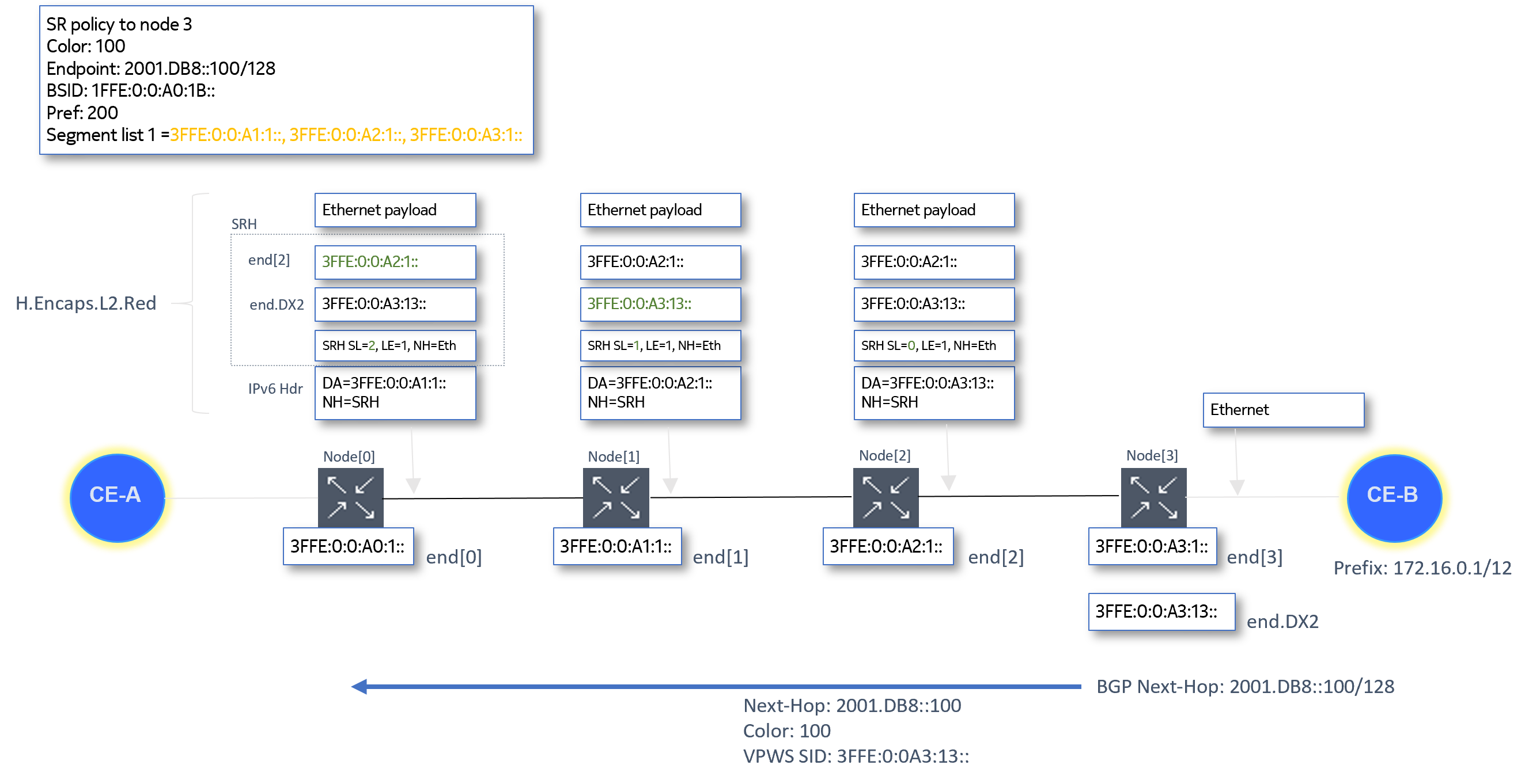
Static SRv6 policies
Set the type to srv6 and only commands relevant to SRv6 policies can be configured. The default value is sr-mpls. If the type is set to sr-mpls, only MPLS labels can be configured for the binding SID and the segments in the segment lists.configure router segment-routing sr-policies static-policy type
Configure SRv6 SIDS for each segment in the segment lists of the SRv6 policy. SRv6 SIDs are 128-bit IPv6 addresses.configure router segment-routing sr-policies static-policy segment-list segment srv6-sidNote: The static SRv6 policy can only be administratively enabled if its type is SRv6 and all its segments have SRv6 SIDs.
Configure the binding SID. The binding SID is mandatory. The system supports only one binding SID per SRv6 policy. The locator or the ip-address command in the binding-sid context configure the value of the binding SID. The locator and the ip-address commands are mutually exclusive. The command to use depends on the configuration of the configure router segment-routing sr-policies static-policy head-end command:configure router segment-routing sr-policies static-policy segment-routing-v6 binding-sid-
If the head end is a non-local IP address, use the ip-address command to configure an SRv6 binding SID for a remote SRv6 policy. The address is a 128-bit IPv6 address. The router does not perform any local checks on the configured address.Note: The non-local head end can only be an IPv4-formatted address to match the head end BGP router ID, which can only be IPv4.
- If the head end is configured as local, configure
the locator name, function, and function value for the SRv6 binding SID
in the following
context:
configure router segment-routing sr-policies static-policy segment-routing-v6 binding-sid locatorThe router checks that a corresponding locator exists in the configure router segment-routing segment-routing-v6 context.
The function is a binding SID function for the static SRv6 policy and can only be end-b6-encaps-red. The datapath implements the End.B6.Encaps.Red as the End.B6 function for the binding SID.
The function value is optional. If configured, the router checks the availability of the value for the configured locator. If a function value is not configured (default), the router dynamically allocates one for the function.
-
BGP SRv6 policies
The router supports BGP extensions for SRv6 policies as defined in draft-ietf-idr-segment-routing-te-policy-11 Advertising Segment Routing Policies in BGP. BGP uses the sr-policy-ipv6 address family for SR policies with SAFI SR Policy (73).
SRv6 segment lists are signaled using a series of SRv6 SID sub-TLVs, as follows:
- Segment sub-TLV Type B – SID only, in the form of an IPv6 address
- SRv6 binding SID sub-TLV
The SRv6 endpoint behavior sub-TLV is not included.
SRv6 binding SID procedures
The router supports one binding SID per SRv6 policy. The application of binding SIDs for SRv6 policies is similar to those for SR policies with an MPLS data plane. The binding SID is programmed using the function type End.B6.Encaps.Red (as defined in RFC 8986).
Binding SIDs for local static SRv6 policies
- a locator name
- a function type
- a function value (optional)
- The locator name must be configured.
- The function type must be configured. Only
end-b6-encaps-red is supported.Note: The procedures defined in RFC 8986 for the End.B6.Encaps.Red function mean that a maximum of two SRv6 policies can be concatenated to provide an end-to-end path using binding SIDs with this function.
- A function value can optionally be configured. If a value is configured, it is considered static. If no value is configured, the router tries to allocate a dynamic value for the function within the named locator.
- The binding SID function value uses the rules for the named locator:
-
The named locator has a static and a dynamic range.
If a static value is configured, the router checks and allocates within the static range for the locator. If no static value is configured, the router allocates a value within the dynamic range.
-
The named locator uses a reserved global function block from which statically and dynamically allocated function values of all locators can be drawn.
The router checks and allocates the value within the reserved global function block.
-
All above checks fail.
The SRv6 policy is not programmed. The router retries the checks at a later time. The allocation scheme for the binding SID function values is first-come-first-served.
-
Binding SIDs for non-local static SRv6 policies
If the head end is not local, the router advertises the SRv6 policy in BGP toward the head end router.
The binding SID is a 128-bit IPv6 address. The router performs no local checks on the binding SID value. The router advertises the binding SID in BGP using the SRv6 binding SID sub-TLV, see BGP SRv6 policies. The SRv6 endpoint behavior sub-TLV is not included.
Receiving and programing BGP SRv6 policy routes
In general, the behavior for received SRv6 policy routes is similar to IPv4 SR-MPLS policies. For an SRv6 policy imported through BGP, the binding SID type is the indicator of the type of the SR policy. If the binding SID is an SRv6 binding SID, the router performs a longest prefix match against the route.
If there is no match, the SRv6 policy (candidate path) is invalid.
- If the function value collides with an already allocated function value within the static range for the locator matching the binding SID (or within the static part of a reserved global function block for the locator, if this is configured), the programming fails. If there is no collision with an already allocated static function value (regardless of the function type), the router allocates the function value to the End.B6.Encaps.Red function for the binding SID. The allocation is on a first-come-first-served basis.
- If a received SRv6 policy includes a SID structure TLV associated with the binding SID sub-TLV or the SRv6 segment sub-TLV, the router ignores it.
- If a received SRv6 policy route contains more than one SRv6 binding SID TLV, the router treats the path as invalid.
If the binding SID is valid, the router programs the SRv6 policy. The binding SID is programmed as a full /128 address.
Tunnel table support for SRv6 policies
Each tunnel in the tunnel table has a protocol owner. The router programs SRv6 polices in TTMv6 with srv6-pol as protocol owner.
If two SR policies have the same color and endpoint but a different technology (MPLS and SRv6), the router programs a separate tunnel for each.
The router treats the TTM preference for SRv6 policies the same as for MPLS-based SR policies. The router populates the TTMv6 tunnel table with the SRv6 tunnel for the SRv6 policy. IGP provides the most accurate MTU value and programs the SR tunnel MTU value in the TTM. The MTU value includes the lowest MTU among the ECMP next hops or the primary/LFA next hops for each remote locator tunnel and local adjacency SID tunnel.
Next the MTU of the SRv6 policy is derived as follows:
SRv6 policy support for Layer 2 and Layer 3 services
The following services can resolve their next hop over an SRv6 policy in TTMv6:
- VPRNv4
- VPRNv6
- EVPN VPLS and VPWS
- BGP Shortcuts
- EVPN IFL
As with MPLS SR policies, the next hop resolution is based on the color (if present) and on the comparison of the next hop with the SR policy endpoint. The color, the endpoint, and the head end define a matching policy, but a matching policy can be an SR MPLS policy or an SRv6 policy. Therefore, the service also uses the data plane technology of the policy to select the tunnel type to resolve over. The following restrictions apply:
- MPLS services cannot resolve over SRv6 tunnels
- SRv6 services can only resolve over SRv6 tunnels
An SRv6 service cannot fall back to an MPLS tunnel type. Suppose the configuration of the resolution allows an SRv6 policy, but an SRv6 policy with a matching color and endpoint does not exist in TTMv6. In that case, the SRv6 service can fall back to any SRv6 shortest path tunnel in TTMv6 or RTM, if the locator of the tunnel matches the locator of the SRv6 service.
-
tunnel-table
This command option resolves the route directly to a tunnel in TTMv6. The system tries to find an SRv6 policy with a matching color and endpoint for BGP routes received with an SRv6 TLV and containing an SRv6 service SID in the IPv6 tunnel table. If no such SRv6 policy is found, the resolution fails.
-
route-table
This command option resolves the route to a shortest-path SRv6 tunnel. If none is found, the resolution fails. This is the default behavior.
-
fallback-tunnel-to-route-table
This command options first tries resolving the route directly to a tunnel in the IPv6 tunnel table. If none is found, fall back to the shortest-path SRv6 resolution. If no such SRv6 policy is found, the resolution fails.
Use the resolution command in the following contexts to configure the resolution options:
- For BGP
shortcuts
configure router bgp segment-routing-v6 family - For VPRN
services
configure service vprn bgp-ipvpn segment-routing-v6 - For EVPN
services
configure service epipe bgp-evpn segment-routing-v6configure service vpls bgp-evpn segment-routing-v6 - For EVPN-IFL
services
configure service vprn bgp-evpn segment-routing-v6
Seamless BFD and end-to-end protection for SRv6 policies
S-BFD and end-to-end protection, using Linear or ECMP protection modes, are supported for static and BGP SRv6 policies. To configure S-BFD and, optionally, a protection mode, apply a maintenance policy to a static or BGP SRv6 policy. The router attempts to establish a S-BFD session on each segment list of the SRv6 policy.
See "Seamless BFD and End to End Protection for SR Policies" for information about how to configure S-BFD and protection. Only S-BFD with a routed return path is supported. That is, the S-BFD reply packet must be sent using a routed path from the reflector.
Controlled return path is not supported for S-BFD over SRv6 policies.
S-BFD packets are encapsulated in the SRv6 policy packet using a segment routing header which includes a SID containing the endpoint address of the SRv6 policy as the last SID of the header. The following figure shows S-BFD encapsulation over an SRv6 policy.
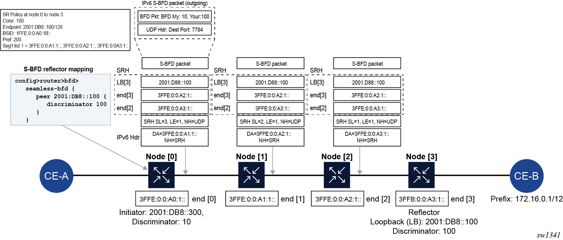
IS-IS saves SID sub-TLVs for endpoint behavior values that it does not support, if received from a third-party implementation. However, it only uses End and End.X endpoint behaviors in RLFA and TI-LFA.
BGP advertises the supported endpoint behaviors End.DT4, End.DT6, End.DT46, and End.DX2 and accepts any behavior codepoint with a supported NLRI type.
BGP advertises the supported endpoint behaviors and accepts any behavior codepoint with a supported NLRI type.