System management
System management parameters
System management commands allow you to configure basic system management functions such as the system name, the router’s location and coordinates, and Common Language Location Identifier (CLLI) code as well as time zones, Network Time Protocol (NTP), Simple Network Time Protocol (SNTP) properties, CRON and synchronization properties.
On SR OS routers, it is possible to query the DNS server for IPv6 addresses. By default, the DNS names are queried for A-records only (address-preference is IPv4-only). If the address-preference is set to IPv6 first, the DNS server is queried for AAAA-records first, and if there is no successful reply, then A-records.
System information
This section describes system information components.
Name
You can configure a name for the system device. The name is used in the prompt string. Only one system name can be configured. If multiple system names are configured the last one encountered overwrites the previous entry. Use the following command to configure the system name.
configure system nameContact
Use the contact command to specify the name of a system administrator, IT staff member, or other administrative entity. Use the following command to configure the system contact.
configure system contactLocation
Use the location command to specify the system location of the device. For example, enter the city, building address, floor, room number, and so on, where the router is located. Use the following command to configure the system location.
configure system locationCoordinates
You can optionally configure the GPS location of the device. If the string contains special characters (#, $, spaces, and so on), the entire string must be enclosed within double quotes. Use the following command to configure the system coordinates.
configure system coordinatesNaming objects
Do not configure named objects with a name that starts with ‟_tmnx_”, or with ‟_” in general.
Common language location identifier
A CLLI code string for the device is an 11-character standardized geographic identifier that uniquely identifies the geographic location of places and specific functional categories of equipment unique to the telecommunications industry. The CLLI code is stored in the Nokia Chassis MIB tmnxChassisCLLICode object.
The CLLI code can be any ASCII-printable text string of up to 11 characters.
DNS security extensions
DNS Security (DNSSEC) Extensions are now implemented in the SR OS, allowing operators to configure DNS behavior of the router to evaluate whether the Authenticated Data bit was set in the response received from the recursive name server and to trust the response, or ignore it.
System time
SR-series routers are equipped with a real-time system clock for time keeping purposes. When set, the system clock always operates on Coordinated Universal Time (UTC), but the SR-series routers OS software has options for local time translation as well as system clock synchronization.
Time zones
Setting a time zone in SR OS allows for times to be displayed in the local time rather instead of UTC. SR OS has both user-defined and system-defined time zones.
A user-defined time zone has a user-assigned name of up to four printable ASCII characters in length and is unique from the system-defined time zones. For user-defined time zones, the offset from UTC is configured as well as any summer time adjustment for the time zone.
configure system time prefer-local-timelog filenames and log header information
times in rollback information
times in rollback and configuration files header information
times related to CRON scripts
times in the event handler system
-
times in NETCONF and gRPC date-and-time leafs
configure log log-id time-formatThe SR OS system-defined time zones are listed in System-defined time zones, which includes both time zones with and without summer time correction.
Acronym |
Time zone name | UTC offset |
|---|---|---|
Europe |
||
GMT |
Greenwich Mean Time |
UTC |
BST |
British Summer Time |
UTC +1 |
IST |
Irish Summer Time |
UTC +1* |
WET |
Western Europe Time |
UTC |
WEST |
Western Europe Summer Time |
UTC +1 |
CET |
Central Europe Time |
UTC +1 |
CEST |
Central Europe Summer Time |
UTC +2 |
EET |
Eastern Europe Time |
UTC +2 |
EEST |
Eastern Europe Summer Time |
UTC +3 |
MSK |
Moscow Time |
UTC +3 |
MSD |
Moscow Summer Time |
UTC +4 |
US and Canada |
||
AST |
Atlantic Standard Time |
UTC -4 |
ADT |
Atlantic Daylight Time |
UTC -3 |
EST |
Eastern Standard Time |
UTC -5 |
EDT |
Eastern Daylight Saving Time |
UTC -4 |
ET |
Eastern Time |
Either as EST or EDT, depending on place and time of year |
CST |
Central Standard Time |
UTC -6 |
CDT |
Central Daylight Saving Time |
UTC -5 |
CT |
Central Time |
Either as CST or CDT, depending on place and time of year |
MST |
Mountain Standard Time |
UTC -7 |
MDT |
Mountain Daylight Saving Time |
UTC -6 |
MT |
Mountain Time |
Either as MST or MDT, depending on place and time of year |
PST |
Pacific Standard Time |
UTC -8 |
PDT |
Pacific Daylight Saving Time |
UTC -7 |
PT |
Pacific Time |
Either as PST or PDT, depending on place and time of year |
HST |
Hawaiian Standard Time |
UTC -10 |
AKST |
Alaska Standard Time |
UTC -9 |
AKDT |
Alaska Standard Daylight Saving Time |
UTC -8 |
Australia |
||
AWST |
Western Standard Time (such as Perth) |
UTC +8 |
ACST |
Central Standard Time (such as Darwin) |
UTC +9.5 |
AEST |
Eastern Standard/Summer Time (such as Canberra) |
UTC +10 |
NTP
NTP is the Network Time Protocol defined in RFC 1305, Network Time Protocol (Version 3) Specification, Implementation and Analysis and RFC 5905, Network Time Protocol Version 4: Protocol and Algorithms Specification. It allows for the participating network nodes to keep time more accurately and more importantly they can maintain time in a more synchronized fashion between all participating network nodes.
SR OS uses an NTP process based on a reference build provided by the Network Time Foundation. Nokia strongly recommends that the users review RFC 8633, Network Time Protocol Best Current Practices, when they plan to use NTP with the router. The RFC section ‟Using Enough Time Sources” indicates that using only two time sources (NTP servers) can introduce instability if they provide conflicting information. To maintain accurate time, Nokia recommends configuring three or more NTP servers.
NTP uses stratum levels to define the number of hops from a reference clock. The reference clock is considered to be a stratum-0 device that is assumed to be accurate with little or no delay. Stratum-0 servers cannot be used in a network. However, they can be directly connected to devices that operate as stratum-1 servers. A stratum-1 server is an NTP server with a directly-connected device that provides Coordinated Universal Time (UTC), such as a GPS or atomic clock.
The higher stratum levels are separated from the stratum-1 server over a network path, therefore, a stratum-2 server receives its time over a network link from a stratum-1 server. A stratum-3 server receives its time over a network link from a stratum-2 server.
SR OS routers normally operate as a stratum-2 or higher device. The router relies on an external stratum-1 server to source accurate time into the network. However, SR OS also allows for the use of the local PTP recovered time to be sourced into NTP. In this latter case, the local PTP source appears as a stratum-0 server and SR OS advertises itself as a stratum-1 server. Activation of the PTP source into NTP may impact the network NTP topology because the SR OS router is promoted to stratum-1.
SR OS router runs a single NTP clock which then operates NTP message exchanges with external NTP clocks. Exchanges can be made with external NTP clients, servers, and peers. These exchanges can be through the base, management, or VPRN routing instances.
NTP operates associations between clocks as either client or server, symmetric active and symmetric passive, or broadcast modes. These modes of operation are applied according to which elements are configured on the router. To run server mode, the operator must enable NTP server mode for the base and each needed VPRN routing instance. To run client mode, the operator must configure external servers. If both the local router and remote router are configured with each other as peers, then the router operates in symmetric active mode. If only one side of the association has peering configured, then the modes are symmetric passive. To operate using broadcast mode, interfaces must be configured to transmit as broadcast servers or receive as broadcast clients.
NTP server operation for both unicast and broadcast communication within a VPRN is configured within the VPRN (see the NTP Within a VPRN Service section in 7450 ESS, 7750 SR, 7950 XRS, and VSR Layer 3 Services Guide: IES and VPRN).
The following NTP elements are supported:
server mode
In this mode, the node advertises the ability to act as a clock source for other network elements. The node, by default, transmits NTP packets in NTP version 4 mode.
authentication keys
Authentication keys implement increased security support in carrier and other networks. Both DES and MD5 authentication are supported, as well as multiple keys.
operation in symmetric active mode
This capability requires that NTP be synchronized with a specific node that is considered more trustworthy or accurate than other nodes carrying NTP in the system. This mode requires that a specific peer is set.
server and peer addressing using IPv6
Both external servers and external peers may be defined using IPv6 or IPv4 addresses. Other features (such as multicast, broadcast) use IPv4 addressing only.
broadcast or multicast modes
When operating in these modes, the node receives or sends using either a multicast (default 224.0.1.1) or a broadcast address. Multicast is supported only on the CPM MGMT port.
alert when NTP server is not available
When none of the configured servers are reachable on the node, the system reverts to manual timekeeping and issues a critical alarm. When a server becomes available, a trap is issued indicating that standard operation has resumed.
NTP and SNTP
If both NTP and SNTP are enabled on the node, then SNTP transitions to an operationally down state. If NTP is removed from the configuration or shut down, then SNTP resumes an operationally up state.
gradual clock adjustment
As several applications (such as Service Assurance Agent (SAA)) can use the clock, and if determined that a major (128 ms or more) adjustment needs to be performed, the adjustment is performed by programmatically stepping the clock. If a minor (less than 128 ms) adjustment must be performed, then the adjustment is performed by either speeding up or slowing down the clock.
To avoid the generation of too many events/trap the NTP module rates limit the generation of events/traps to three per second. At that point a single trap is generated that indicates that event/trap squashing is taking place.
Synchronization
Synchronization between the CPMs includes the following:
CRON
The CRON feature supports periodic and date and time-based scheduling in SR OS. CRON can be used, for example, to schedule Service Assurance Agent (SAA) functions. CRON functionality includes the ability to specify scripts that need to be run, when they are scheduled, including one-time only functionality (one-shot), interval and calendar functions. Scheduled reboots, peer turn ups, service assurance agent tests and more can all be scheduled with CRON, as well as OAM events, such as connectivity checks, or troubleshooting runs.
CRON supports the schedule element. The schedule function configures the type of schedule to run, including one-time only (one-shot), periodic, or calendar-based runs. All runs are determined by month, day of month or weekday, hour, minute, and interval (seconds).
High availability
This section discusses the high availability (HA) routing options and features available to service providers that help diminish vulnerability at the network or service provider edge and alleviate the effect of a lengthy outage on IP networks.
High availability is an important feature in service provider routing systems. High availability is gaining momentum because of the unprecedented growth of IP services and applications in service provider networks driven by the demand from the enterprise and residential communities. Downtime can be very costly, and, in addition to lost revenue, customer information and business-critical communications can be lost. High availability is the combination of continuous uptime over long periods (Mean Time Between Failures (MTBF)) and the speed at which failover or recovery occurs (Mean Time To Repair (MTTR)).
The popularity of high availability routing is evident at the network or service provider edge where thousands of connections are hosted and rerouting options around a failed piece of equipment can often be limiting. Or, a single access link exists to a customer because of additional costs for redundant links. As service providers converge business-critical services such as real-time voice (VoIP), video, and VPN applications over their IP networks, high availability becomes much more stringent compared to the requirements for best-effort data. Network and service availability become critical aspects when offering advanced IP services which dictates that IP routers that are used to construct the foundations of these networks be resilient to component and software outages.
For high availability configuration information, see Synchronization and redundancy.
HA features
As more and more critical commercial applications move onto the IP/MPLS networks, providing high availability services becomes increasingly important. This section describes high availability features for routers. Most of these features only apply to routers with two Control Processor Modules (CPM).
Redundancy
The redundancy features enable the duplication of data elements and software functionality to maintain service continuation in case of outages or component failure.
See the 7450 ESS, 7750 SR, and VSR Multiservice ISA and ESA Guide for information about redundancy for the Integrated Service Adapter (ISA).
Software redundancy
Software outages are challenging even when baseline hardware redundancy is in place. There should be a balance to provide high availability routing otherwise router problems typically propagate not only throughout the service provider network, but also externally to other connected networks possibly belonging to other service providers. This could affect customers on a broad scale. Presently, there are several software availability features that contribute to the percentage of time that a router is available to process and forward traffic.
To fully appreciate high availability, you should realize that all routing protocols specify minimum time intervals in which the peer device must receive an acknowledgment before it disconnects the session.
OSPF default session timeout is approximately 40 seconds. The timeout intervals are configurable.
BGP default session timeout is approximately 120 seconds. The timeout intervals are configurable for the 7750 SR and 7950 XRS only.
Therefore, router software has to recover faster than the specified time interval to maintain up time.
Configuration redundancy
Features configured on the active device CPM are saved on the standby CPM as well. When the active device CPM fails, these features are brought up on the standby device CPM that takes over the mastership.
Even with modern modular and stable software, the failure of route processor hardware or software can cause the router to reboot or cause other service impacting events. In the best circumstances, failure leads to the initialization of a redundant route processor, which hosts the standby software configuration, to become the active processor. The following options are available.
warm standby
The router image and configuration is already loaded on the standby route processor. However, the standby could still take a few minutes to become effective because it must first re-initialize connections by bringing up Layer 2 connections and Layer 3 routing protocols and then rebuild routing tables.
hot standby
The router image, configuration, and network state is already loaded on the standby and it receives continual updates from the active route processor and the swapover is immediate. However, hot standby affects conventional router performance as more frequent synchronization increases consumption of system resources. Nokia’s newer generation service routers address this issue because they already have extra processing built into the system.
Component redundancy
Component redundancy is critical to reduce MTTR for the system and primarily consists of the following router features:
dual route processor modules
For a highly available architecture, redundant Control Processor Modules (CPM) are essential. The route processing functions of the CPM calculate the most efficient route to an Internet destination and communicate the best path information to peer routers. Rapid information synchronization between the primary and secondary CPMs is crucial to minimize recovery time.
switch fabric (SFM) redundancy
Failure of a single switch fabric card can occur with little to no loss of traffic.
redundant line cards
LAG, ECMP and other techniques are employed to spread traffic over multiple line cards so that a failure of one line card does not impact the services being delivered.
redundant power supply
A power module can be removed without impact on traffic.
redundant fan
Failure of a fan module can occur without impacting traffic.
hot swap
Components in a live system can be replaced or become active without taking the system down or affecting traffic flow to/from other modules.
Router hardware architecture plays a key role in the availability of the system. The principle router architecture styles are centralized and distributed. In these architectures, both active and standby route processors, I/O modules (IOMs) (also called line cards), fans, and power supplies maintain a low MTTR for the routing system.
However, in a centralized architecture, packet processing and forwarding is performed in a central shared route processor and the individual line cards are relatively simple. The cards rely solely on the route processor for routing and forwarding intelligence and, should the centralized route processor fail, there is greater impact to the system overall, as all routing and packet forwarding stops.
In a distributed system, the packet forwarding functionality is situated on each line card. Distributing the forwarding engines off the central route processor and positioning one on each line card lowers the impact of route processor failure as the line cards can continue to forward traffic during an outage.
The distributed system is better suited to enable the convergence of business critical services such as real-time voice (VoIP), Video, and VPN applications over IP networks with superior performance and scalability. The centralized architecture can be prone to performance bottleneck issues and limits service offerings through poor scalability which may lead to customer and service SLA violations.
Service redundancy
All service-related statistics are kept during a switchover. Services, SDPs, and SAPs remains up with a minimum loss of forwarded traffic during a CPM switchover.
Accounting configuration redundancy
When there is a switchover and the standby CPM becomes active, the accounting servers are checked and if they are administratively up and capable of coming online (media present, and so on), the standby is brought online and new accounting files are created at that point. Users must manually copy the accounting records from the failed CPM.
Nonstop forwarding
In a control plane failure or a forced switchover event, the router continues to forward packets using the existing stale forwarding information. Nonstop forwarding requires clean control plane and data plane separation. Usually the forwarding information is distributed to the IOMs, XCMs and XMAs.
Nonstop forwarding is used to notify peer routers to continue forwarding and receiving packets, even if the route processor (control plane) is not working or is in a switch-over state. Nonstop forwarding requires clean control plane and data plane separation and usually the forwarding information is distributed to the line cards. This method of availability has both advantages and disadvantages. Nonstop forwarding continues to forward packets using the existing stale forwarding information during a failure. This may cause routing loops and black holes, and also requires that surrounding routers adhere to separate extension standards for each protocol. Every router vendor must support protocol extensions for interoperability.
NSR
With nonstop routing (NSR) on the SR-series router devices, routing neighbors are unaware of a routing process fault. If a fault occurs, a reliable and deterministic activity switch to the inactive control complex occurs such that routing topology and reachability are not affected, even in the presence of routing updates. NSR achieves high availability through parallelization by maintaining up to date routing state information, at all times, on the standby route processor. This capability is achieved independently of protocols or protocol extensions, providing a more robust solution than graceful restart protocols between network routers.
The NSR implementation on the SR-series routers supports all routing protocols. NSR makes it possible to keep the existing sessions (BGP, LDP, OSPF, and so on) during a CPM switchover, including support for MPLS signaling protocols. Peers do not see any change.
Protocol extensions are not required. There are no interoperability issues and there is no need to define protocol extensions for every protocol. Unlike nonstop forwarding and graceful restart, the forwarding information in NSR is always up to date, which eliminates possible blackholes or forwarding loops.
Traditionally, addressing high availability issues have been patched through non-stop forwarding solutions. With the implementation of NSR, these limitations are overcome by delivering an intelligent hitless failover solution. This enables a carrier-class foundation for transparent networks, required to support business IP services backed by stringent SLAs. This level of high availability poses a major issue for conventional routers whose architectural design limits or prevents them from implementing NSR.
CPM switchover
During a switchover, system control and routing protocol execution are transferred from the active to the standby CPM.
An automatic switchover may occur under the following conditions:
A fault condition that causes the active CPM to crash or reboot.
The active CPM is declared down (not responding).
Online removal of the active CPM.
A manual switchover can occur if a switchover is forced from an active CPM to a standby, using the admin redundancy force-switchover command. Use the following command to configure a batch file that executes automatically after a CPM failover:
- MD-CLI
configure redundancy switchover-exec - classic
CLI
configure system switchover-exec
Synchronization
Synchronization between the CPMs includes the following:
Configuration and boot-env synchronization
Use the following command to configure synchronization for the configuration and boot environment.
configure redundancy synchronizeUse commands in the following context to perform manual synchronization.
admin redundancy synchronizeState database synchronization
If a new standby CPM is inserted into the system, it synchronizes with the active CPM upon a successful boot process.
If the standby CPM is rebooted, it synchronizes with the active CPM upon a successful boot process.
When configuration or state changes occur, an incremental synchronization is conducted from the active CPM to the standby CPM.
show redundancy synchronizationadmin reboot standbySynchronization and redundancy
SR-series routers supporting redundancy use a 1:1 redundancy scheme. Redundancy methods facilitate system synchronization between the active and standby Control Processor Modules (CPMs) so they maintain identical operational parameters to prevent inconsistencies in the event of a CPM failure.
When automatic system synchronization is enabled for an entity, any save or delete file operations configured on the primary, secondary or tertiary choices on the active CPM file system are mirrored in the standby CPM file system.
Although software configurations and images can be copied or downloaded from remote locations, synchronization can only occur locally between compact flash drives (cf1:, cf2:, and cf3:).
Synchronization can occur either:
-
automatically
Automatic synchronization is disabled by default. You configure automatic synchronization for the BOF, boot.ldr, configuration, YANG schema, and image files or you can configure it for only the configuration files. Use the following commands to configure which types of changes cause automatic synchronization.
configure redundancy synchronize boot-env
configure redundancy synchronize config
If the schema YANG files are not found, the files are not copied but the rest of the synchronization is not affected.
Automatic synchronization also occurs whenever the BOF is modified and when you execute an admin save command with no file URL specified.
manually
You can manually synchronize the BOF, boot.ldr, configuration, YANG schema, and image files, only the configuration files, or the imported certificate/key/CRL files. Use the following commands to perform manual synchronization:- MD-CLI
admin redundancy synchronize boot-environment admin redundancy synchronize configuration - classic CLI
admin redundancy synchronize boot-env
admin redundancy synchronize config
admin redundancy synchronize cert
Note: Use the classic CLI command to manually synchronize certificate, key, and CRL files.- MD-CLI
Active and standby designations
Typically, the first Switch Fabric (SF)/CPM card installed in a redundant SR-series router chassis assumes the role as active, regardless of whether it is inserted in Slot A or B. The next CPM installed in the same chassis then assumes the role as the standby CPM. If two CPM are inserted simultaneously (or almost simultaneously) and are booting at the same time, then preference is given to the CPM installed in Slot A.
If only one CPM is installed in a redundant router device, then it becomes the active CPM regardless of the slot it is installed in.
The active and standby designations can be visually determined by LEDs on the CPM/CCM faceplate. See the appropriate platform Installation Guide for LED indicator details.
The following example shows the output when the CPM installed in Slot A is acting as the active CPM and the CPM installed in Slot B is acting as the standby.
Show card command output on the 7950 XRS
===============================================================================
Card Summary
===============================================================================
Slot   Provisioned Type                            Admin Operational   Comments
           Equipped Type (if different)            State State
-------------------------------------------------------------------------------
1      xcm-x20                                     up    provisioned
A      cpm-x20                                     up    up/active
B      cpm-x20                                     up    up/standby
===============================================================================
The following example shows the console message when a CPM boots, sees an active CPM, and becomes the standby CPM.
Console message for CPM switch to standby
...
Slot A contains the Active CPM
This CPM (Slot B) is the Standby CPM
When the active CPM goes offline
When an active CPM goes offline (because of reboot, removal, or failure), the standby CPM takes control without rebooting or initializing itself. It is assumed that the CPMs are synchronized, therefore, there is no delay in operability. When the CPM that went offline boots and then comes back online, it becomes the standby CPM.
When the standby CPM comes online, the following output is shown.
Active CPM in Slot A has stopped
Slot B is now active CPM


Attempting to exec configuration file:
'cf3:/config.cfg' ...

...

Executed 49,588 lines in 8.0 seconds from file cf3:\config.cfg
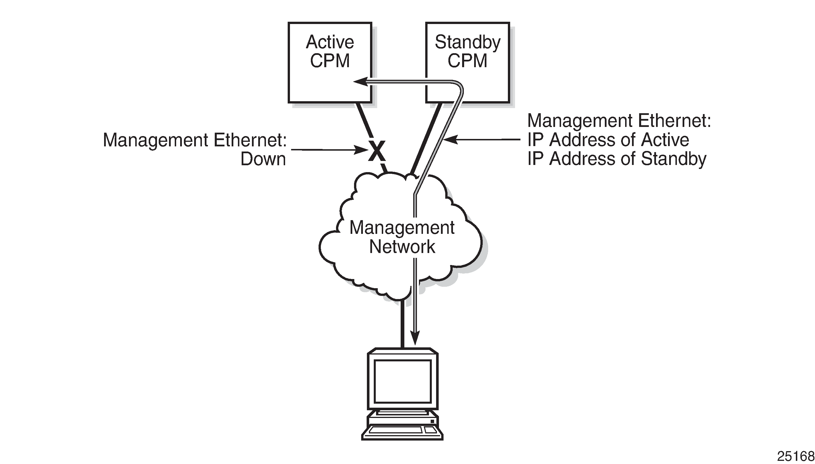
OOB management Ethernet port redundancy
The SR OS platform provides a resilient out-of-band (OOB) management Ethernet redundancy mode for system management.
When the management Ethernet port is down on the active CPM, the OOB Ethernet redundancy feature allows the active CPM to use the management Ethernet port of the standby CPM, as shown in Management Ethernet: normal mode and Management Ethernet: redundancy mode.
Use the following command to enable OOB management Ethernet port redundancy:
configure redundancy mgmt-ethernet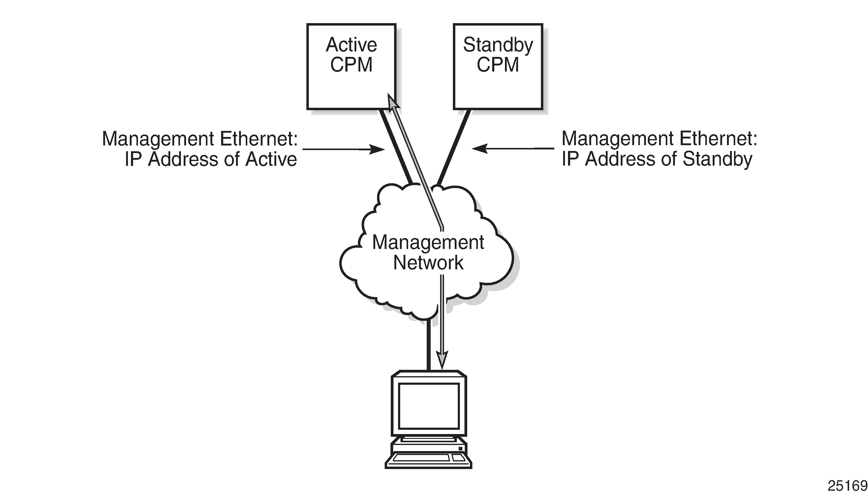
Persistence
The persistence feature on the 7750 SR allows information learned through DHCP snooping across reboots to be kept. This information can include data such as the IP address, MAC binding information, lease length information, and ingress SAP information (required for VPLS snooping to identify the ingress interface). This information is referred to as the DHCP lease-state information.
When a DHCP message is snooped, there are steps that make the data persistent in a system with dual CPMs. In systems with only one CPM, only Step 1 applies. In systems with dual CPMs, all steps apply.
When a DHCP ACK is received from a DHCP server, the entry information is written to the active CPM Compact Flash. If writing was successful, the ACK is forwarded to the DHCP client. If persistency fails completely (bad cflash), a trap is generated indicating that persistency can no longer be guaranteed. If the complete persistency system fails the DHCP ACKs are still forwarded to the DHCP clients. Only during small persistency interruptions or in overload conditions of the Compact Flash, DHCP ACKs may get dropped and not forwarded to the DHCP clients.
DHCP message information is sent to the standby CPM and also there the DHCP information is logged on the Compact Flash. If persistency fails on the standby also, a trap is generated.
DDP access optimization for DHCP leases
A high rate of DHCP renewals can create a load on the compact flash file system when subscriber management and DHCP server persistence is enabled. To optimize the access to the Dynamic Data Persistency (DDP) files on the compact flash, a lease-time threshold can be specified that controls the eligibility of a DHCP lease for persistency updates when no other data other than the lease expiry time is to be updated.
The following example shows the configuration of a DHCP lease-time threshold.
MD-CLI
[ex:/configure system persistence]
A:admin@node-2# info
    dhcp-server {
        location cf2
    }
    subscriber-mgmt {
        location cf2
    }
    options {
        dhcp-leasetime-threshold 90061
    }
classic CLI
A:node-2>config>system>persistence# info
----------------------------------------------
            subscriber-mgmt
                location cf2:
            exit
            dhcp-server
                location cf2:
            exit
            options
                dhcp-leasetime-threshold days 1 hrs 1 min 1 sec 1
            exit
----------------------------------------------
When the offered lease time of the DHCP lease is less than the configured threshold, the lease is flagged to skip persistency updates and is installed with its full lease time upon a persistency recovery after a reboot.
The dhcp-leasetime-threshold command controls persistency updates for:
-
DHCPv4 and DHCPv6 leases for a DHCP relay or proxy (enabled with persistence subscriber-mgmt)
-
DHCPv4 leases for DHCP snooping in a VPLS service (enabled with persistence subscriber-mgmt)
-
DHCPv4 and DHCPv6 leases for a DHCP server (enabled with persistence dhcp-server)
To check if a DHCP relay or proxy lease is flagged to skip persistency updates, use the tools dump persistence submgt record record-key CLI command. When flagged to skip persistency updates, the persistency record output includes ‟Skip Persistency Updates: true”.
To check if a DHCP server lease is flagged to skip persistency updates, use the tools dump persistence dhcp-server record record-key CLI command. When flagged to skip persistency updates, the persistency record output includes ‟lease mode : LT” (LT = Lease Time) and a ‟lease time : …” field. When not flagged to skip persistency updates, the persistency record output includes ‟lease mode : ET” (ET = Expiry Time) and an ‟expires : …” field.
Network synchronization
This section describes network synchronization capabilities available on SR OS platforms. These capabilities involve multiple approaches to network timing; namely SDH/SONET, Synchronous Ethernet, BITS, and Adaptive clocking and a Precision Time Protocol (PTP) IEEE 1588v2. These features address barriers to entry by:
Providing synchronization quality required by the mobile space; such as radio operations and circuit emulation services (CES) transport.
Augmenting and potentially replacing the existing (SONET/SDH) timing infrastructure and delivering high quality network timing for time sensitive applications in the wireline space.
Network synchronization is commonly distributed in a hierarchical PTP topology at the physical layer as shown in Conventional network timing architecture (North American nomenclature).
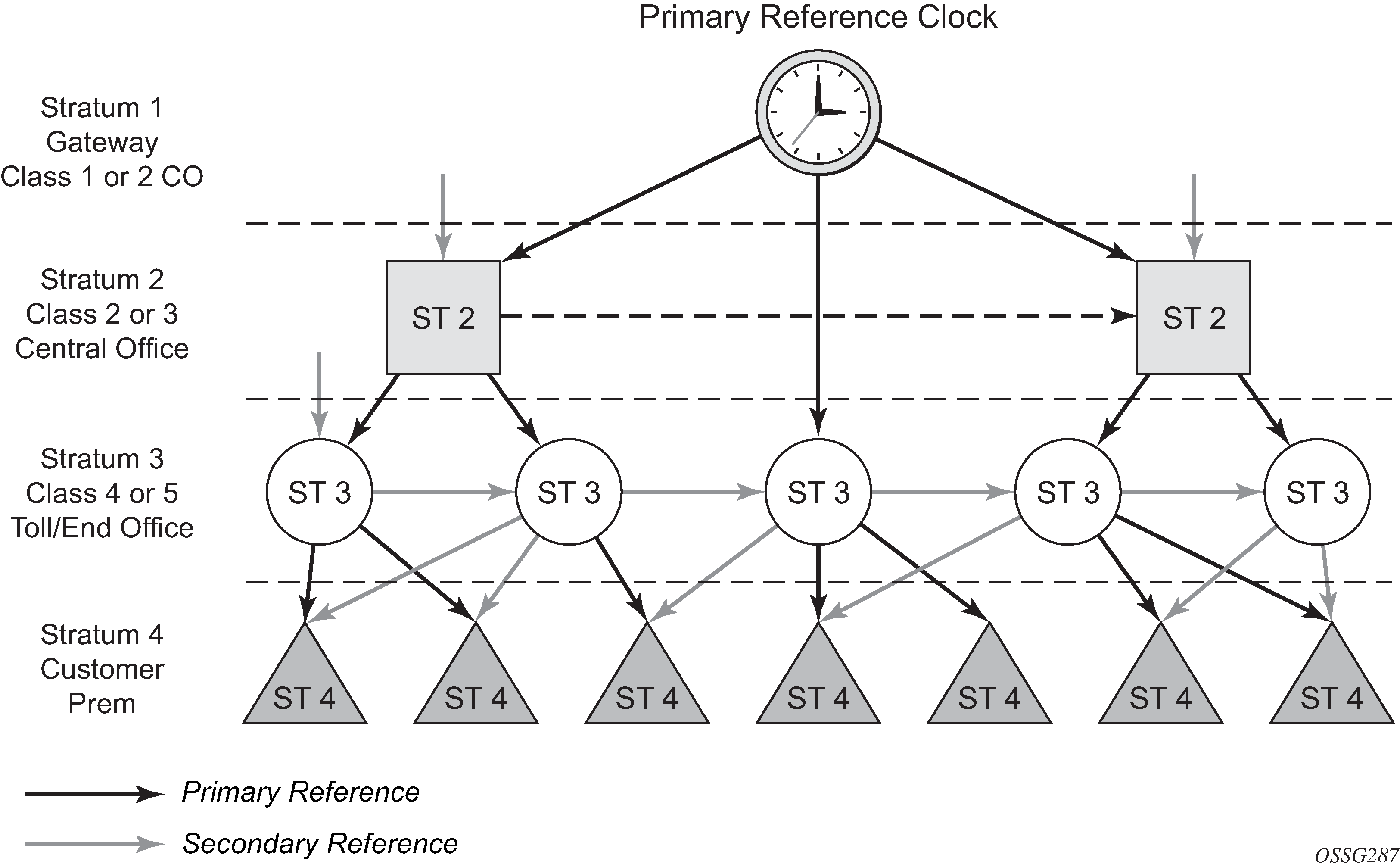
The architecture shown in Conventional network timing architecture (North American nomenclature) provides the following benefits:
Limits the need for high quality clocks at each network element and only requires that they reliably replicate input to remain traceable to its reference.
Uses reliable physical media to provide transport of the timing signal; it does not consume any bandwidth and requires limited additional processing.
The synchronization network is designed so a clock always receives timing from a clock of equal or higher stratum or quality level. This ensures that if an upstream clock has a fault condition (for example, loses its reference and enters a holdover or free-run state) and begins to drift in frequency, the downstream clock is able to follow it. For greater reliability and robustness, most offices and nodes have at least two synchronization references that can be selected in priority order (such as primary and secondary).
Further levels of resiliency can be provided by designing a capability in the node clock that operates within prescribed network performance specifications without any reference for a specified time-frame. A clock operating in this mode holds the last known state over (or holdover) until the reference lock is again achieved. Each level in the timing hierarchy is associated with minimum levels of network performance.
Each synchronization capable port can be independently configured to transmit data using the node reference timing or loop timing. In addition, some TDM channels can use adaptive timing.
Transmission of a reference clock through a chain of Ethernet equipment requires that all equipment supports Synchronous Ethernet. A single piece of equipment that is not capable of performing Synchronous Ethernet breaks the chain. Ethernet frames still get through but downstream devices should not use the recovered line timing as it is be traceable to an acceptable stratum source.
Central synchronization subsystem
The timing subsystem for the platforms has a central clock located on the CPM (motherboard). The timing subsystem performs many of the duties of the network element clock as defined by Telcordia (GR-1244-CORE) and ITU-T G.781.
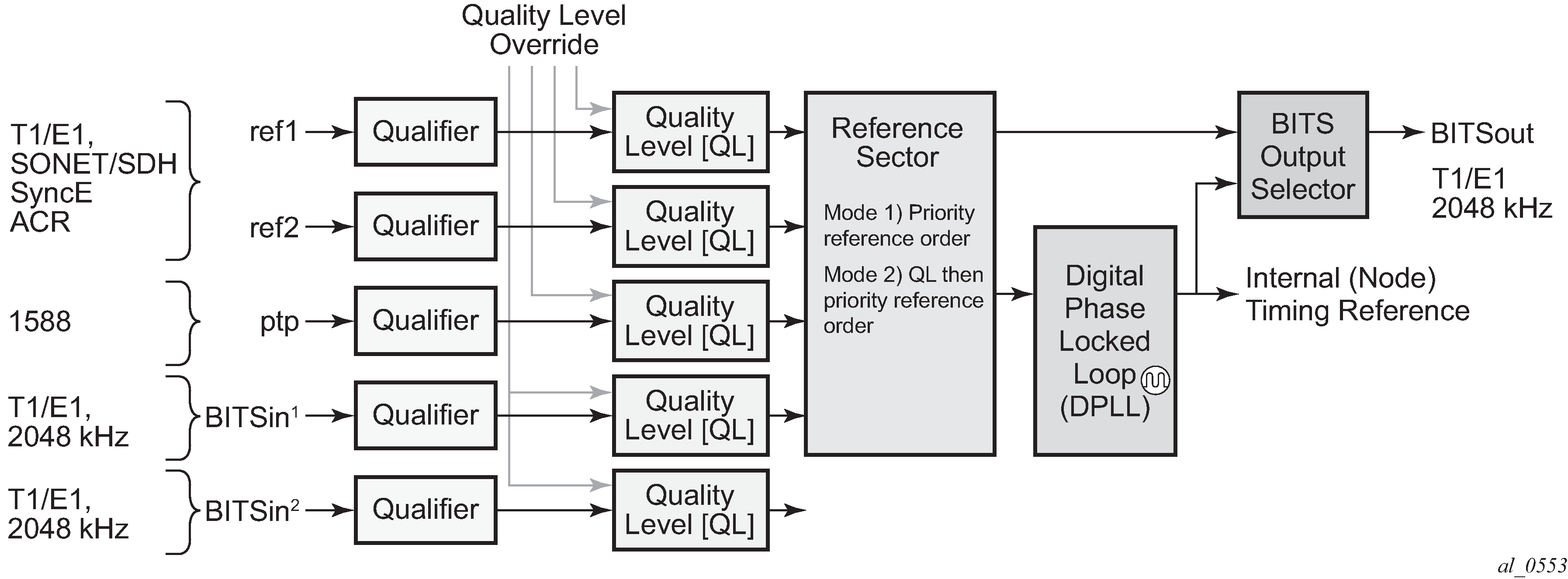
The system can select from up to three (7950 XRS) or four (7450 ESS and 7750 SR) timing inputs to train the local oscillator. The priority order of these references must be specified. This is a simple ordered list of inputs: {bits, ref1, ref2, ptp}. The CPM clock output shall have the ability to drive the clocking for all line cards in the system. The routers support selection of the node reference using Quality Level (QL) indications. See CPM clock synchronization reference selection for a description of the synchronization selection process for the CPM clock.
The recovered clock can derive its timing from any of the following:
OC3/STM1, OC12/STM4, OC48/STM16, OC192/STM64 ports (7450 ESS and 7750 SR only)
T1/E1 CES channel (adaptive clocking) (7750 SR only)
Synchronous Ethernet ports
T1/E1 port (7750 SR only)
BITS port on the CPM or CCM module
10GE ports in WAN PHY mode
IEEE 1588v2 timeReceiver port (PTP) (7450 ESS and 7750 SR only)
SyncE/1588 port on the CPM or the CCM
The BITS ports accept T1 or E1 signal formats. Some hardware also supports the 2048 kHz signal format. The format must be common between all BITSin and BITSout ports.
All settings of the signal characteristics for the BITS input apply to both ports. When the active CPM considers the BITS input as a possible reference, it first considers the BITS input port on the active CPM or CCM followed by the BITS input port on the standby CPM or CCM in that relative priority order. This relative priority order is in addition to the user-definable ref-order. For example, a ref-order of bits ref1 ref2 would actually be BITS in (active CPM or CCM), followed by BITS in (standby CPM or CCM), followed by ref1, followed by ref2. When ql-selection is enabled, the QL of each BITS input port is viewed independently. The higher QL source is chosen.
When the active CPM considers the SyncE/1588 as a possible reference, the active CPM first considers the SyncE/1588 port on the active CPM or CCM, followed by the SyncE/1588 port on the standby CPM or CCM in that relative priority order. This relative priority order is in addition to the user-definable ref-order. For example, a ref-order of synce ref1 ref2 would actually be SyncE/1588 (active CPM or CCM), followed by SyncE/1588 (standby CPM or CCM), followed by ref1, followed by ref2. When ql-selection is enabled, the QL of each SyncE/1588 input port is viewed independently. The higher QL source is chosen.
The following behavior applies to the platform architecture existing on 7750 SR-7/12/12e, 7750 SR-2s/7s/14s, 7750 SR-1e/2e/3e, 7750 SR-a4/a8, and 7450 ESS-7/12. When the BITS or SyncE port on the standby CPM is an option as input reference into the central clock of the active CPM, a display of the central clock data on the standby CPM indicates that it is locked to its local BITS or SyncE input. This is expected behavior and required to make the BITS input on the standby available to the active CPM as an option for reference selection.
The restrictions on the location for the source-port or source-bits for ref1 and ref2 are listed in Ref1 and ref2 timing references.
| Platform | Ref1 slots | Ref2 slots | Notes |
|---|---|---|---|
7450 ESS-7 |
1 to 2 |
3 to 5 |
— |
7450 ESS-12 |
1 to 5 |
6 to 10 |
— |
7750 SR-1 |
1 |
1 |
Ref1 and ref2 cannot be on the same MDA |
7750 SR-7 |
1 to 2 |
3 to 5 |
— |
7750 SR-12 |
1 to 5 |
6 to 10 |
— |
7750 SR-12e |
1 to 5 |
6 to 9 |
— |
7750 SR-a4 |
1 |
1 |
Ref1 and ref2 cannot be on the same MDA. Two CPMs must be installed to allow two references to be used. |
7750 SR-a8 |
1 to 2 |
1 to 2 |
Ref1 and ref2 cannot be on the same slot. |
7750 SR-1e |
1 |
1 |
Ref1 and ref2 cannot be on the same MDA |
7750 SR-2e |
1 to 2 |
1 to 2 |
Ref1 and ref2 cannot be on the same MDA |
7750 SR-3e |
1 to 3 |
1 to 3 |
Ref1 and ref2 cannot be on the same MDA |
7750 SR-1s |
1 |
1 |
Ref1 and ref2 cannot be on the same MAC chip. See the 7750 SR-1s Installation Guide or use the show datapath command for the mappings. |
7750 SR-2s |
1 to 2 |
1 to 2 |
Ref1 and ref2 cannot be on the same slot. |
7750 SR-7s |
1 to 6 |
1 to 6 |
Ref1 and ref2 cannot be on the same slot. Slot 6 cannot be used if a CPM has been installed in that slot. |
7750 SR-14s |
1 to 6 |
1 to 6 |
Ref1 and ref2 cannot be on the same slot. |
7950 XRS-20 |
1 to 10 |
1 to 10 |
Ref1 and ref2 cannot be on the same slot |
7950 XRS-20e |
1 to 10 |
1 to 10 |
Ref1 and ref2 cannot be on the same slot |
7950 XRS-40 |
1 to 10 |
1 to 10 |
Ref1 and ref2 cannot be on the same slot |
The BITS output ports can be configured to provided either the unfiltered recovered line clock from a line card port or the output of the central clock. The first case would be used if the port was connected to deliver an input reference directly to dedicated timing device in the facility (BITS or SASE device). The second case would be used to test the quality of the clocking used by the router.
When QL selection mode is disabled, then the reversion setting controls when the central clock can re-select a previously failed reference.
Revertive, non-revertive timing reference switching operation shows the selection followed for two reference in both revertive and non-revertive modes:
| Status of reference A | Status of reference B | Active reference non-revertive case | Active reference revertive case |
|---|---|---|---|
OK |
OK |
A |
A |
Failed |
OK |
B |
B |
OK |
OK |
B |
A |
OK |
Failed |
A |
A |
OK |
OK |
A |
A |
Failed |
Failed |
holdover |
holdover |
OK |
Failed |
A |
A |
Failed |
Failed |
holdover |
holdover |
Failed |
OK |
B |
B |
Failed |
Failed |
holdover |
holdover |
OK |
OK |
A or B |
A |
7950 XRS-40 extension chassis central clocks
The central clock architecture previously described applies to each chassis of the 7950 XRS-40. There is a central clock located on each of the CPMs present in the extension chassis. However, there is no configuration for the central clocks on the CPMs of the extension chassis. The central clocks only use the BITS input ports of the extension chassis for their input reference. It is assumed that the quality of the reference provided into the BITS input ports of the extension chassis CPMs is equal to the quality of the Master chassis central clocks. See the Installation Guide for appropriate physical cabling to support this architecture.
SSM
Synchronization status messages (SSM) provide a mechanism to allow the synchronization distribution network to both determine the quality level of the clock sourcing a specific synchronization trail and to allow a network element to select the best of multiple input synchronization trails. Synchronization Status messages have been defined for various transport protocols including SONET/SDH, T1/E1, and Synchronous Ethernet, for interaction with office clocks, such as BITS or SSUs and embedded network element clocks.
SSM allows equipment to autonomously provision and reconfigure (by reference switching) their synchronization references, while helping to avoid the creation of timing loops. These messages are particularly useful to allow synchronization reconfigurations when timing is distributed in both directions around a ring.
The following sections provide details about the SSM message functionality for different signal types. These functions apply to all platforms that support the signal type.
DS1 signals
DS1 signals can carry an indication of the quality level of the source generating the timing information using the SSM transported within the 1544 kb/s Extended Super Frame (ESF) Data Link (DL) of the signal as specified in Recommendation G.704. No such provision is extended to SF formatted DS1 signals.
The format of the data link messages in ESF frame format is "0xxx xxx0 1111 1111", transmitted rightmost bit first. The six bits denoted "xxx xxx" contain the actual message; some of these messages are reserved for synchronization messaging. It takes 32 frames (such as 4 ms) to transmit all 16 bits of a complete DL.
E1 signals
E1 signals can carry an indication of the quality level of the source generating the timing information using the SSM as specified in Recommendation G.704.
One of the Sa4 to Sa8 bits, (the actual Sa bit is for operator selection), is allocated for Synchronization Status Messages. To prevent ambiguities in pattern recognition, it is necessary to align the first bit (San1) with frame 1 of a G.704 E1 multi-frame.
The numbering of the San (n = 4, 5, 6, 7, 8) bits. A San bit is organized as a 4-bit nibble San1 to San4. San1 is the most significant bit; San4 is the least significant bit.
The message set in San1 to San4 is a copy of the set defined in SDH bits 5 to 8 of byte S1.
SONET/SDH signals
The SSM of SDH and SONET interfaces is carried in the S1 byte of the frame overhead. Each frame contains the four bit value of the QL.
DS3/E3
DS3/E3 signals are not required to be synchronous. However, it is acceptable for their clocking to be generated from a synchronization source. The 7750 SR and the 7450 ESS allow E3/DS3 physical ports to be specified as a central clock input reference.
DS3/E3 signals do not support an SSM channel. QL-override should be used for these ports if ql-selection is enabled
Synchronous Ethernet
Traditionally, Ethernet-based networks employ the physical layer transmitter clock to be derived from an inexpensive +/-100ppm crystal oscillator and the receiver locks onto it. There is no need for long term frequency stability because the data is packetized and can be buffered. For the same reason there is no need for consistency between the frequencies of different links. However, you can derive the physical layer transmitter clock from a high quality frequency reference by replacing the crystal with a frequency source traceable to a primary reference clock. This would not affect the operation of any of the Ethernet layers, for which this change would be transparent. The receiver at the far end of the link would lock onto the physical layer clock of the received signal, and therefore gain access to a highly accurate and stable frequency reference. Then, in a manner analogous to conventional hierarchical network synchronization, this receiver could lock the transmission clock of its other ports to this frequency reference and a fully time synchronous network could be established.
The advantage of using Synchronous Ethernet, compared with methods that rely on sending timing information in packets over an unclocked physical layer, is that it is not influenced by impairments introduced by the higher levels of the networking technology (packet loss, packet delay variation). Hence, the frequency accuracy and stability may be expected to exceed those of networks with unsynchronized physical layers.
Synchronous Ethernet allows operators to gracefully integrate existing systems and future deployments into conventional industry-standard synchronization hierarchy. The concept behind synchronous Ethernet is analogous to SONET/SDH system timing capabilities. It allows the operator to select any (optical) Ethernet port as a candidate timing reference. The recovered timing from this port is then used to time the system (for example, the CPM locks to this configured reference selection). The operator then could ensure that any of system output would be locked to a stable traceable frequency source.
If the port is a fixed copper Ethernet port and in 1000BASE-T mode of operation, there is a dependency on the 802.3 link timing for the Synchronous Ethernet functionality (see ITU-T G.8262). The 802.3 link timing states must align with the wanted direction of Synchronous Ethernet timing flow. When a fixed copper Ethernet port is specified as an input reference for the node or when it is removed as an input reference for the node, an 802.3 link auto-negotiation is triggered to ensure the link timing aligns properly.
The SSM of Synchronous Ethernet uses an Ethernet OAM PDU that uses the slow protocol subtype. For a complete description of the format and processing, see ITU-T G.8264.
Clock source quality level definitions
The following clock source quality levels have been identified for the purpose of tracking network timing flow. These levels make up all of the defined network deployment options documented in Recommendation G.803 and G.781. The Option I network is a network developed on the original European SDH model; whereas, the Option II network is a network developed on the North American SONET model.
In addition to the QL values received over SSM of an interface, the standards also define additional codes for internal use. These include the following:
QL INVx is generated internally by the system if and when an unallocated SSM value is received, where x represents the binary value of this SSM. All of these independent values are assigned as the singled value of QL-INVALID.
QL FAILED is generated internally by the system if and when the terminated network synchronization distribution trail is in the signal fail state.
There is also an internal quality level of QL-UNKNOWN. This is used to differentiate from a received QL-STU code but is equivalent for the purposes of QL selection.
Synchronization message coding and source priorities — SSM value received on port lists the synchronization message coding and source priorities for SSM received.
| SSM value received on port | ||||
|---|---|---|---|---|
| SDH interface SyncE interface in SDH mode |
SONET interface SyncE interface in SONET mode |
E1 interface | T1 interface (ESF) | Internal relative quality level |
0010 (prc) |
0001 (prs) |
0010 (prc) |
00000100 11111111 (prs) |
1 - Best quality |
0000 (stu) |
00001000 11111111 (stu) |
2 |
||
0111 (st2) |
00001100 11111111 (ST2) |
3 |
||
0100 (ssua) |
0100 (tnc) |
0100 (ssua) |
01111000 11111111 (TNC) |
4 |
1101 (st3e) |
01111100 11111111 (ST3E) |
5 |
||
1000 (ssub) |
1000 (ssub) |
6 |
||
1010 (st3/eec2) |
00010000 11111111 (ST3) |
7 |
||
1011 (sec/eec1) |
1011 (sec) |
8 - Lowest quality qualified in QL-enabled mode |
||
1100 (smc) |
00100010 11111111 (smc) |
9 |
||
00101000 11111111 (st4) |
10 |
|||
1110 (pno) |
01000000 11111111 (pno) |
11 |
||
1111 (dnu) |
1111 (dus) |
1111 (dnu) |
00110000 11111111 (dus) |
12 |
Any other |
Any other |
Any other |
N/A |
13- QL_INVALID |
14- QL-FAILED |
||||
15 - QL-UNC |
||||
Synchronization message coding and source priorities — SSM values transmitted by interface of types lists the synchronization message coding and source priorities for SSM transmitted.
| SSM values to be transmitted by interface of type | ||||
|---|---|---|---|---|
| Internal relative quality level | SDH interface SyncE interface in SDH mode |
SONET interface SyncE interface in SONET mode |
E1 interface | T1 interface (ESF) |
1 - Best quality |
0010 (prc) |
0001 (PRS) |
0010 (prc) |
00000100 11111111 (PRS) |
2 |
0100 (ssua) |
0000 (stu) |
0100 (ssua) |
00001000 11111111 (stu) |
3 |
0100 (ssua) |
0111 (st2) |
0100 (ssua) |
00001100 11111111 (st2) |
4 |
0100 (ssua) |
0100 (tnc) |
0100 (ssua) |
01111000 11111111 (tnc) |
5 |
1000 (ssub) |
1101 (st3e) |
1000 (ssub) |
01111100 11111111 (st3e) |
6 |
1000 (ssub) |
1010 (st3/eec2) |
1000 (ssub) |
00010000 11111111 (st3) |
7 |
1011 (sec/eec1) |
1010 (st3/eec2) |
1011 (sec) |
00010000 11111111 (st3) |
8 - Lowest quality qualified in QL-enabled mode |
1011 (sec/ eec1) |
1100 (smc) |
1011 (sec) |
00100010 11111111 (smc) |
9 |
1111 (dnu) |
1100 (smc) |
1111 (dnu) |
00100010 11111111 (smc) |
10 |
1111 (dnu) |
1111 (dus) |
1111 dnu |
00101000 11111111 (st4) |
11 |
1111 (dnu) |
1110 (pno) |
1111 (dnu) |
01000000 11111111 (pno) |
12 |
1111 (dnu) |
1111 (dus) |
1111 (dnu) |
00110000 11111111 (dus) |
13- QL_INVALID |
1111 (dnu) |
1111 (dus) |
1111 (dnu) |
00110000 11111111 (dus) |
14- QL-FAILED |
1111 (dnu) |
1111 (dus) |
1111 (dnu) |
00110000 11111111 (dus) |
15 - QL-UNC |
1011 (sec/eec1) |
1010 (st3/eec2) |
1011 (sec) |
00010000 11111111 (st3) |
Advanced G.781 features
The central clock of the node supports several advanced features of the G.781 standard. These include the specification of a minimum acceptable QL value for the input references, the specification of a minimum acceptable QL value for the BITS output port, the ability to squelch the BITS output signal, and the specification of a Wait To Restore timer for input references. These features allow for more options in the management of the synchronization topology.
IEEE 1588v2 PTP
Precision Time Protocol (PTP) is a timing-over-packet protocol defined in the IEEE 1588v2 standard 1588 PTP 2008.
PTP may be deployed as an alternative timing-over-packet option to Adaptive Clock Recovery (ACR). PTP provides the capability to synchronize network elements to a Stratum-1 clock or primary reference clock (PRC) traceable frequency source over a network that may or may not be PTP-aware. PTP has several advantages over ACR. It is a standards-based protocol, has lower bandwidth requirements, can transport both frequency and time, and can potentially provide better performance.
Support is provided for an ordinary clock in timeReceiver or timeTransmitter mode or a boundary clock. When configured as an ordinary clock timeTransmitter, PTP can only be used for the distribution of a frequency reference, not a time reference. The boundary clock and ordinary clock timeReceiver can be used for both frequency and time distribution.
The ordinary clock timeTransmitter, ordinary clock timeReceiver, and boundary clock communicate with neighboring IEEE 1588v2 clocks. These neighbor clocks can be ordinary clock timeTransmitters, ordinary clock timeReceivers, or boundary clocks. The communication can be based on either unicast IPv4 sessions transported through IP interfaces or multicast Ethernet transported through Ethernet ports.
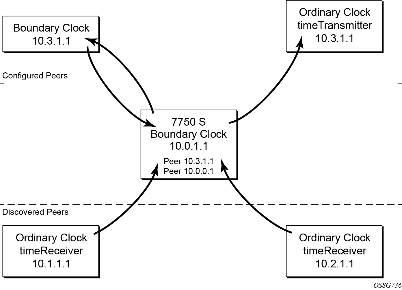
For the unicast IP sessions, the external clocks are labeled 'peers'. There are two types of peers: configured and discovered. An ordinary clock timeReceiver or a boundary clock should have configured peers for each PTP neighbor clock from which it may accept synchronization information. The router initiates unicast sessions with all configured peers. An ordinary clock timeTransmitter or boundary clock accepts unicast session requests from external peers. If the peer is not a configured peer, then it is considered a discovered peer. An ordinary clock timeTransmitter or boundary clock can deliver synchronization information toward discovered peers. Peer clocks shows the relationship of various neighbor clocks using unicast IP sessions to communicate with a 7750 SR configured as a boundary clock with two configured peers.
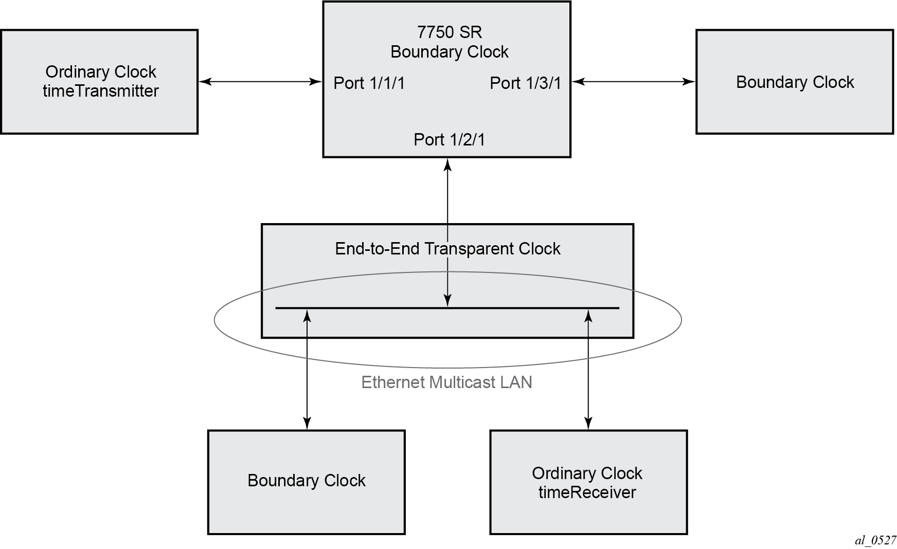
For multicast Ethernet operation, the router listens for and transmit PTP messages using the configured multicast MAC address. Neighbor clocks are discovered via the reception of messages through an enabled Ethernet port. An ordinary clock timeTransmitter, ordinary clock timeReceiver, and a boundary clock support more than one neighbor PTP clock connecting into a single port. This may be encountered with the deployment of an Ethernet multicast LAN segment between the local clock and the neighbor PTP ports using an end-to-end transparent clock or an Ethernet switch. The Ethernet switch is not recommended because of the introduction of PDV and the potential degradation of performance but it can be used if appropriate to the application. Ethernet multicast ports shows the relationship of various neighbor clocks using multicast Ethernet sessions to a 7750 SR configured as a boundary clock. The 7750 SR has three ports configured for multicast Ethernet communications. Port 1/2/1 of the 7750 SR shows a connection where there are two neighbor clocks connecting to one port of the 7750 SR through an end-to-end transparent clock.
The ordinary clock timeTransmitter, ordinary clock timeReceiver, and boundary clock allow for PTP operation over both unicast IPv4 and multicast Ethernet at the same time.
The IEEE 1588v2 standard includes the concept of PTP profiles. These profiles are defined by industry groups or standards bodies that define how IEEE 1588v2 is to be used for a particular application.
The following profiles are supported:
IEEE 1588v2 (ieee1588-2008)
G.8265.1 (g8265dot1-2010)
G.8275.1 (g8275dot1-2014)
-
G.8275.2 (g8275dot2-2016)
When an ordinary clock timeReceiver or a boundary clock receive Announce messages from one or more configured peers or multicast neighbors, it executes a Best TimeTransmitter Clock Algorithm (BTCA) to determine the state of communication between itself and the peers. The system uses the BTCA to create a hierarchical topology allowing the flow of synchronization information from the best source (the grandmaster clock) out through the network to all boundary and timeReceiver clocks. Each profile has a dedicated BTCA.
If the profile setting for the clock is ieee1588-2008, the precedence order for the BTCA is as follows:
-
priority1
-
clockClass
-
clockAccuracy
-
PTP variance (offsetScaledLogVariance)
-
priority2
-
clockIdentity
-
stepsRemoved from the grandmaster
The ordinary clock timeTransmitter, ordinary clock timeReceiver, and boundary clock set their local parameters as listed in Local clock parameters when profile is set to ieee1588-2008.
| Parameter | Value |
|---|---|
clockIdentity |
Chassis MAC address following the guidelines of 7.5.2.2.2 of IEEE 1588 |
clockClass |
13 — local clock configured as ordinary clock timeTransmitter and is locked to an external reference 14 — local clock configured as ordinary clock timeTransmitter and in holdover after having been locked to an external source 248 — local clock configured as ordinary clock timeTransmitter and is in free run or the router is configured as a boundary clock 255 — local clock configured as ordinary clock timeReceiver |
clockAccuracy |
FE — unknown |
offsetScaledLogVariance |
FFFF — not computed |
If the profile setting for the clock is g8265dot1-2010, the precedence order for the best timeTransmitter selection algorithm is:
-
clockClass
-
priority
The ordinary clock timeTransmitter, ordinary clock timeReceiver, and boundary clock set their local parameters as listed in Local clock parameters when profile is set to itu-telecom-freq.
| Parameter | Value |
|---|---|
clockClass |
80-110 — value corresponding to the QL out of the central clock as per Table 1/G.8265.1 255 — the clock is configured as ordinary clock timeReceiver |
The g8265dot1-2010 profile is for use in an environment with only ordinary clock timeTransmitters and timeReceivers for frequency distribution.
If the profile setting for the clock is g8275dot1-2014, the precedence order for the best timeTransmitter selection algorithm is very similar to that used with the default profile. It ignores priority1, includes a localPriority and includes the ability to force a port to never enter timeReceiver state (timeTransmitter-only).
The precedence is as follows:
-
clockClass
-
clockAccuracy
-
PTP variance (offsetScaledLogVariance)
-
priority2
-
localPriority
-
clockIdentity (See Note)
-
stepsRemoved from the grandmaster
The ordinary clock timeTransmitter, ordinary clock timeReceiver, and boundary clock set their local parameters as listed in Local clock parameters when profile is set to g8275dot1-2014.
| Parameter | Value |
|---|---|
clockIdentity |
Chassis MAC address following the guidelines of 7.5.2.2.2 of IEEE 1588 |
clockClass |
165 — local clock configured to a boundary clock and the boundary clock was previously locked to a grandmaster with a clock class of 6 248 — local clock configured as boundary clock 255 — local clock configured as ordinary clock timeReceiver |
clockAccuracy |
FE — unknown |
offsetScaledLogVariance |
FFFF — not computed |
If the profile setting for the clock is g8275dot2-2016, the precedence order for the best master selection algorithm is very similar to that used with the g8275dot1-2014 profile. It ignores the priority1 parameter, includes a localPriority parameter, and includes the ability to force a port to never enter slave state (master-only). The precedence is as follows:
-
clockClass
-
clockAccuracy
-
PTP variance (offsetScaledLogVariance)
-
priority2
-
localPriority
-
clockIdentity
-
stepsRemoved from the grandmaster
If the two clocks being compared have a clockClass of less than 128, the comparison of the clockIdentity is skipped. Skipping the comparison of the clockIdentity is the normal case because the vast majority of clocks used as grandmasters advertise a clockClass of less than 128.
The following table describes the local parameter settings when the profile setting for the clock is g8275dot2-2016.
|
Parameter |
Value and Description |
|---|---|
|
clockIdentity |
Chassis MAC address following the guidelines of 7.5.2.2.2 of IEEE 1588 |
|
clockClass |
6 — local clock is using a time reference from a GNSS receiver 165 — local clock is configured as a boundary clock in holdover; the boundary clock was previously locked to a grand master clock with a clock class of 6 248 — local clock is configured as a grandmaster clock or boundary clock in free-run mode 255 — local clock is configured as an ordinary clock slave |
|
clockAccuracy |
0xFE — unknown 0x21 — when using a time reference from a GNSS receiver |
|
offsetScaledLogVariance |
0xFFFF — not computed 0x4e5d (1.8E-15) — when using a time reference from a GNSS receiver |
There is a limit on the number of external PTP clocks to which the ordinary clock timeReceiver or boundary clock requests unicast service (number of configured peers) and also a limit to the number of external PTP clocks to which the ordinary clock timeTransmitter or boundary clock grants unicast service (number of discovered peers). An association where the boundary clock has a symmetric relationship with another boundary clock (in other words, they both have the other as a configured peer) consumes a request and a grant unicast service in each router.
The number of configured Ethernet ports is not restricted.
There are limits to the maximum transmitted and received event message rates supported in the router. Each unicast IP service established consumes a portion of one of the unicast message limits. When either limit is reached, additional unicast service requests are refused by sending a grant response with zero in the duration field.
See the scaling guide for the appropriate release for the specific unicast message limits related to PTP.
Multicast messages are not considered when validating the unicast message limit. When multicast messaging on Ethernet ports is enabled, the PTP load needs to be monitored to ensure the load does not exceed the capabilities. There are several commands that you can use for this monitoring. If the capacity usage reaches 100%, the PTP software process on the router is at its limit of transmitting and receiving PTP packets.
show system cpuBecause you cannot control the amount of PTP messages being received over the Ethernet ports, you can use statistics commands to identify the source of the message load.
show system ptp statisticsUse the following commands to display received packet rates:
show system ptp port
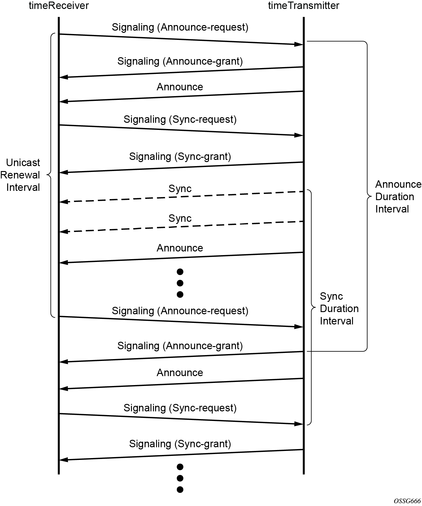
show system ptp port detailMessaging sequence between the PTP timeReceiver clock and PTP timeTransmitter clock shows the unicast negotiation procedure performed between a timeReceiver and a peer clock that is selected to be the timeTransmitter clock. The timeReceiver clock requests Announce messages from all peer clocks but only request Sync and Delay_Resp messages from the clock selected to be the timeTransmitter clock.
PTP clock synchronization
The IEEE 1588v2 standard allows for synchronization of the frequency and time from a timeTransmitter clock to one or more timeReceiver clocks over a packet stream. This packet-based synchronization can be over unicast UDP/IPv4 or multicast Ethernet.
As part of the basic synchronization timing computation, a number of event messages are defined for synchronization messaging between the PTP timeReceiver port and PTP timeTransmitter port. A one-step or two-step synchronization operation can be used, with the two-step operation requiring a follow-up message after each synchronization message. Ordinary clock timeTransmitter and boundary clock timeTransmitter ports use one-step operation; ordinary clock timeReceiver and boundary clock timeReceiver ports can accept messages from either one-step or two-step operation timeTransmitter ports.
The IEEE 1588v2 standard includes a mechanism to control the topology for synchronization distribution. The Best TimeTransmitter Clock Algorithm (BTCA) defines the states for the PTP ports on a clock. One port is set into timeReceiver state and the other ports are set to timeTransmitter (or passive) states. Ports in timeReceiver state recovered synchronization delivered by from an external PTP clock and ports in timeTransmitter state transmit synchronization to toward external PTP clocks.
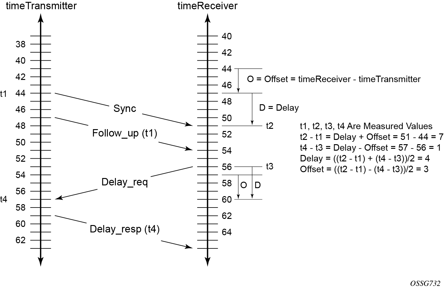
The basic synchronization timing computation between the PTP timeReceiver and PTP timeTransmitter is shown in PTP timeReceiver and timeTransmitter time synchronization computation. This figure illustrates the offset of the timeReceiver clock referenced to the best timeTransmitter signal during startup.
When using IEEE 1588v2 for distribution of a frequency reference, the timeReceiver calculates a message delay from the timeTransmitter to the timeReceiver based on the timestamps exchanged. A sequence of these calculated delays contain information of the relative frequencies of the timeTransmitter clock and timeReceiver clock but has a noise component related to the packet delay variation (PDV) experienced across the network. The timeReceiver must filter the PDV effects so as to extract the relative frequency data and then adjust the timeReceiver frequency to align with the timeTransmitter frequency.
When using IEEE 1588v2 for distribution of time, the 7750 SR and 7450 ESS use the four timestamps exchanged using the IEEE 1588v2 messages to determine the offset between the router time base and the external timeTransmitter clock time base. The router determines the offset adjustment and then in between these adjustments, the router maintains the progression of time using the frequency from the central clock of the router. This allows time to be maintained using a BITS input source or a Synchronous Ethernet input source even if the IEEE 1588v2 communications fail. When using IEEE 1588v2 for time distribution, the central clock should at a minimum have a system timing input reference enabled. Using IEEE 1588v2 for time distribution displays how IEEE 1588v2 is used for time distribution.
Synchronization uncertainty
The PTP protocol uses the BMCA to build the network topology from a PTP grandmaster, through one or more boundary clocks, and into timeReceiver clocks. This mechanism relies on the grandmaster information contained in the Announce messages sent between these clocks. While the BMCA is designed to create the topology quickly and without any timing loops, it does not address the fact that as each clock selects a new parent clock, it takes time for each clock to align its local time to that of its parent clock.
To address this, the IEEE and ITU-T adds the synchronizationUncertain bit to the header of Announce messages. A grandmaster or boundary clock sets this bit to true when it is calibrating. In addition, if this bit is set to true in the Announce messages from its parent clock, the boundary clock always transmits the bit as true. This allows the topology to settle quickly but also provides an indication to the final timeReceiver clocks as to when they can trust the time being delivered by the network.
The optional synchronizationUncertain bit (flagField octet 1, bit 6) defined in the G.8275.1, G.8275.2, and IEEE 1588 specifications in Announce messages indicates the synchronization uncertainty of the PTP clock to the operator and downstream clocks. A synchronizationUncertain bit value of 1 indicates a SyncUncertain TRUE state, meaning the local clock is still in the transient phase and attempting to achieve stability; a synchronizationUncertain bit value of 0 indicates a SyncUncertain FALSE state, meaning the local clock has reached the steady state phase.
The SyncUncertain state transitions to FALSE when all of the following conditions are true for a number of consecutive, stable PTP time update windows:
- the parent PTP clock is in a SyncUncertain FALSE state
- PTP time recovery is locked
- the grandmaster PTP clock is Clock Class 6 or 7
- the central frequency clock is locked, and the quality level of the frequency is QL-PRC/QL-PRS
- PTP frequency recovery is locked if PTP is used for frequency and the profile is IEEE 1588v2
The SyncUncertain state transitions back to TRUE if any of the above conditions are not met, even momentarily, and the stable PTP time update window count resets to 0.
In some deployments, other PTP clocks in the network may not support the synchronizationUncertain bit. If the upstream clocks do not support synchronizationUncertain, the synchronizationUncertain bit is 0, indicating a SyncUncertain FALSE state regardless of the actual state of the local clock. If the downstream clocks do not support synchronizationUncertain, it may be desirable to stop the transmission of Announce messages while the local clock is in a state of SyncUncertain TRUE.
- MD-CLI
configure system ptp tx-while-sync-uncertain false - classic
CLI
configure system no ptp tx-while-sync-uncertain
If this command is used to stop the transmission of Announce messages while the local clock is in a state of SyncUncertain TRUE, unicast negotiation grant requests are not granted and current grants are canceled.
Performance considerations
Although IEEE 1588v2 can be used on a network that is not PTP-aware, the use of PTP-aware network elements (boundary clocks) within the packet-switched network improves synchronization performance by reducing the impact of PDV between the grandmaster clock and the timeReceiver clock. In particular, when IEEE 1588v2 is used to distribute high-accuracy time, such as for mobile base station phase requirements, then the network architecture requires the deployment of PTP awareness in every device between the grandmaster and the mobile base station timeReceiver.
In addition, performance is also improved by the removal of any PDV caused by internal queuing within the boundary clock or timeReceiver clock. This is accomplished with hardware that is capable of detecting and time stamping the IEEE 1588v2 packets at the Ethernet interface. This capability is referred to as port-based time stamping.
Port-based timestamping of PTP messages
To meet the stringent performance requirements of PTP mobile network applications, the 1588 packets must be time-stamped and the ingress and egress ports. This requires the use of 1588 port-based timestamping on the ports handling the PTP messages. This avoids any possible PDV that may be introduced between the port and the CPM. The ability to timestamp in the interface hardware is provided on a subset of the IMM and MDA assemblies of the routers. Generally, all FP4 and later generations of XMA, XMA-s, and MDA-e-XP modules support 1588 port-based timestamping. For other assemblies, contact your Nokia representative to verify the support for 1588 port-based timestamping.
In order for this to operate, the CPM, IOM, IMM, and MDAs must be running firmware that supports this capability. The CPM firmware upgrade occurs automatically when the CPM card software is updated. Because upgrading IOM, IMM, and MDA firmware is service impacting, this upgrade is not performed automatically on a soft reset of the MDA. The IOM/IMM firmware is upgraded when the IOM/IMM card is hard reset. The MDA firmware is programmed during system initialization, when the MDA is inserted, or when the MDA is hard reset via a clear mda or clear card command. However, when an MDA is soft reset via either a clear card soft command or during a major ISSU, the MDA firmware is not updated.
Port-based timestamping of 1588 packets cannot be used at the same time for Ethernet encapsulation and IP encapsulation on a specific port. This means that PTP cannot be configured on an Ethernet port if ptp-hw-assist is already configured on a Layer 3 interface associated with that port. Similarly, ptp-hw-assist cannot be configured on a Layer 3 interface if its associated port is already configured as a PTP port.
PTP capabilities
For each PTP message type to be exchanged between the router and an external 1588 clock, a unicast session must be established using the unicast negotiation procedures. The router allows the configuration of the message rate to be requested from external 1588 clocks. The router also supports a range of message rates that it grants to requests received from the external 1588 clocks. The IEEE 1588 standard allows the grantor port to respond with a shorter duration than what was in the request. The router can accept such a grant and uses that duration. The router issues a renegotiation before the duration expires.
Message rates ranges and defaults describes the ranges for both the rates that the router can request and grant.
| Message type | Rates requested by the 7450 ESS, 7750 SR, 7950 XRS, and VSR | Rates granted by the 7450 ESS, 7750 SR, 7950 XRS, and VSR | ||
|---|---|---|---|---|
| Min | Max | Min | Max | |
Announce |
1 packet every 16 seconds |
8 packets/second |
packet every 16 seconds |
8 packets/second |
Sync |
1 packet/second |
64 packet/second |
1 packet/second |
128 packet/second |
Delay_Resp |
1 packet/second |
64 packets/second |
1 packet/second |
128 packets/second |
(Duration) |
300 |
300 |
1 |
1000 |
State and statistics data for each PTP peer are available to assist in the detection of failures or unusual situations.
PTP ordinary timeReceiver clock for frequency
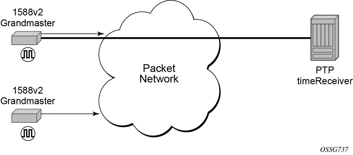
Traditionally, only clock frequency is required to ensure smooth transmission in a synchronous network. The PTP ordinary clock with timeReceiver capability on the router provides another option to reference a Stratum-1 traceable clock across a packet-switched network. The recovered clock can be referenced by the internal SSU and distributed to all slots and ports. timeReceiver clock shows a PTP ordinary timeReceiver clock network configuration.
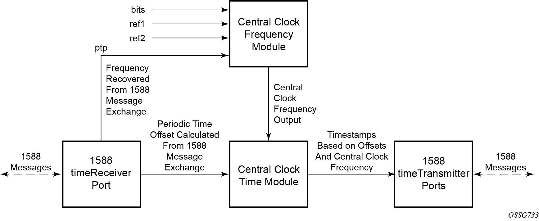
The PTP timeReceiver capability is implemented on the CPM, version 3 or later. The IEEE 1588v2 messages can ingress and egress the router on any line interface. Ordinary timeReceiver clock operation shows the operation of an ordinary PTP clock in timeReceiver mode.
PTP ordinary timeTransmitter clock for frequency
The router supports the PTP ordinary clock in timeTransmitter mode. Normally, an IEEE 1588v2 grandmaster is used to support many timeReceivers and boundary clocks in the network. In cases where only a small number of timeReceivers and boundary clocks exist and only frequency is required, a PTP integrated timeTransmitter clock can greatly reduce hardware and management costs to implement PTP across the network. It also provides an opportunity to achieve better performance by placing a timeTransmitter clock closer to the edge of the network, as close to the timeReceiver clocks as possible. PTP timeTransmitter clock shows a PTP timeTransmitter clock network configuration.
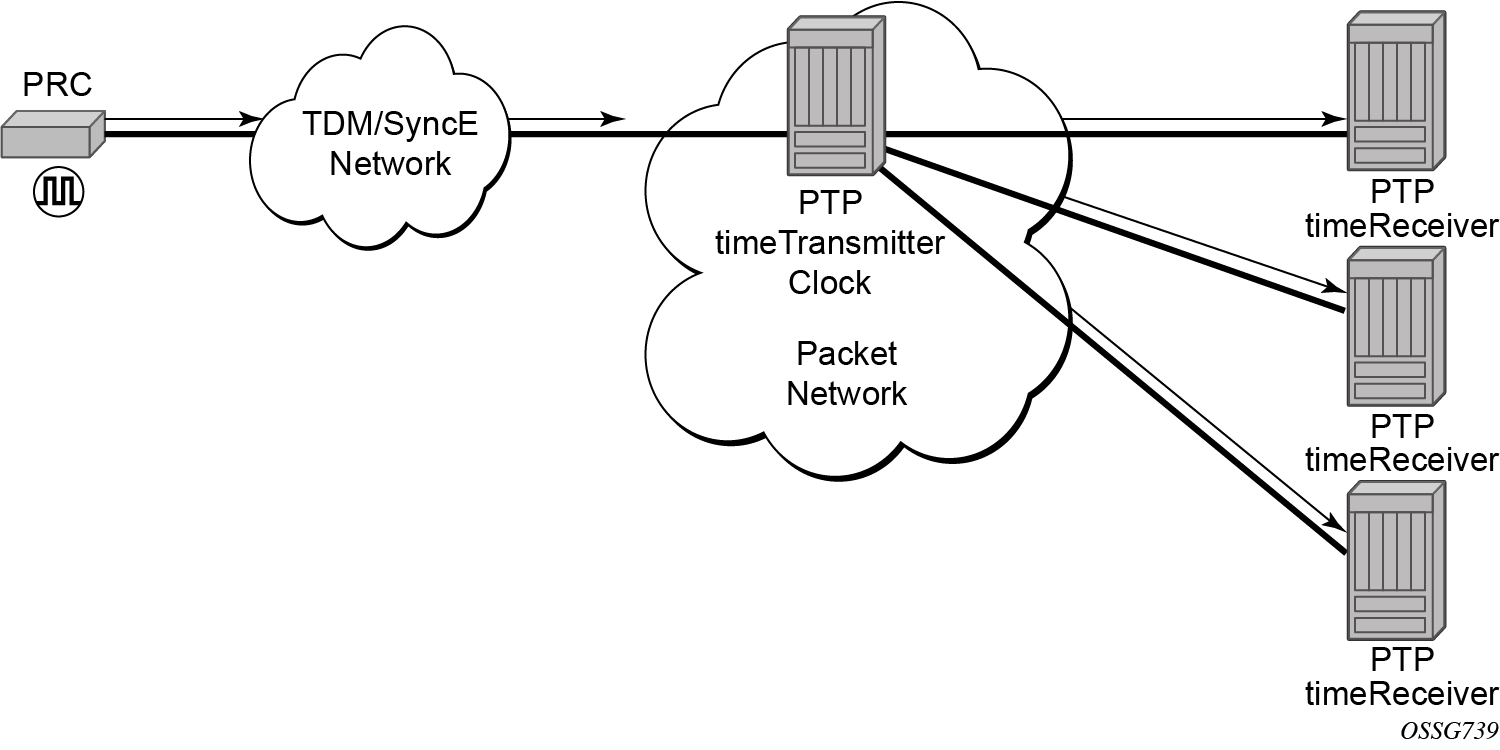
All packets are routed to their destination via the best route as determined in the route table; see Ordinary timeTransmitter clock operation. It does not matter which ports are used to ingress and egress these packets (unless port based time stamping is enabled for higher performance).
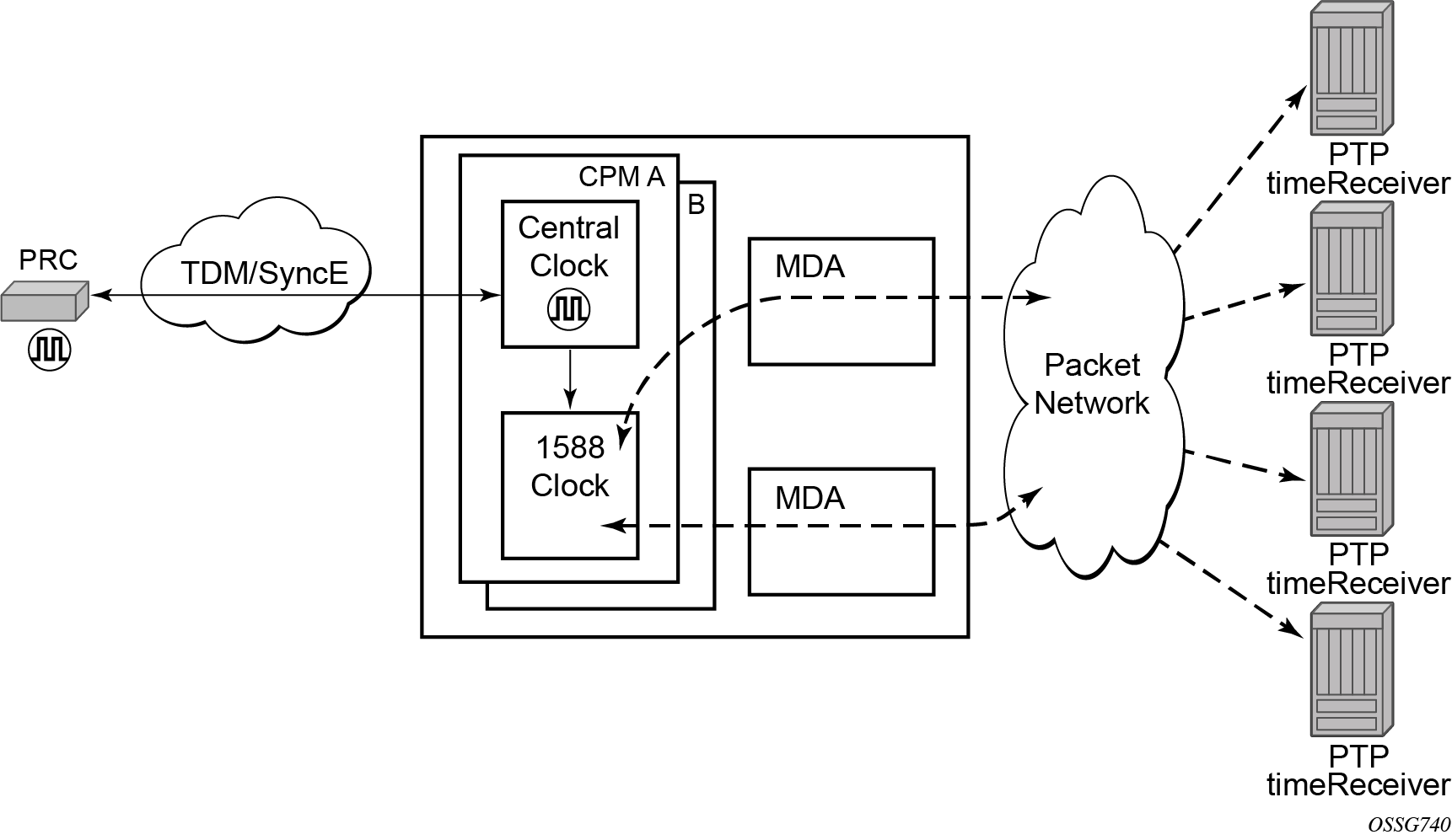
PTP boundary clock for frequency and time
The router supports boundary clock PTP devices in both timeTransmitter and timeReceiver states. IEEE 1588v2 can function across a packet network that is not PTP-aware; however, the performance may be unsatisfactory and unpredictable. PDV across the packet network varies with the number of hops, link speeds, utilization rates, and the inherent behavior of the routers. By using routers with boundary clock functionality in the path between the grandmaster clock and the timeReceiver clock, one long path over many hops is split into multiple shorter segments, allowing better PDV control and improved timeReceiver performance. This allows PTP to function as a valid timing option in more network deployments and allows for better scalability and increased robustness in various topologies, such as rings. Boundary clocks can simultaneously function as a PTP timeReceiver of an upstream grandmaster (ordinary clock) or boundary clock, and as a PTP timeTransmitter of downstream timeReceivers (ordinary clock) and boundary clocks, as shown in Boundary clock.
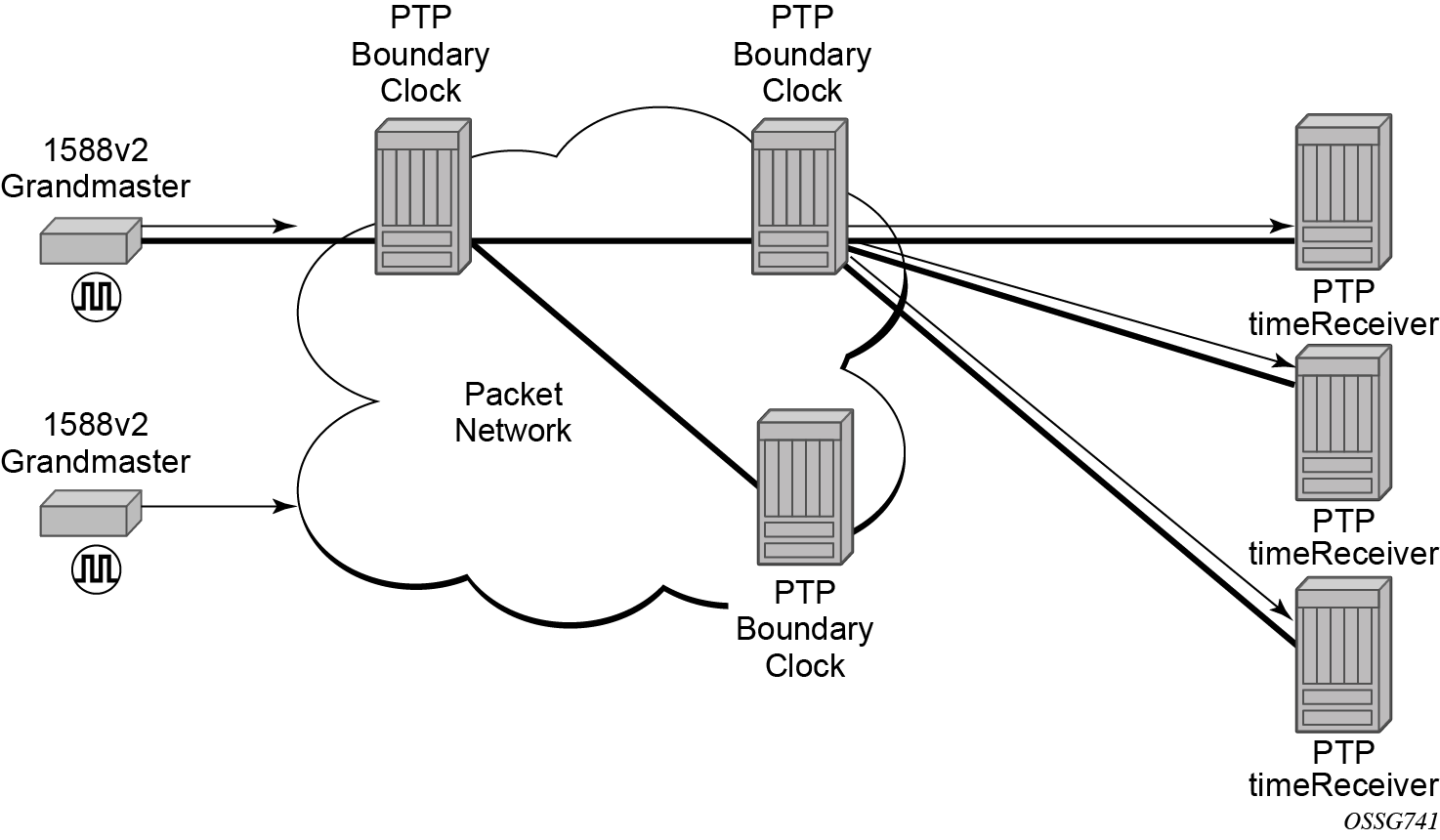
In addition, the use of port-based timestamping in every network element between the grandmaster and the end timeReceiver application is highly recommended for delivering time to meet one microsecond accuracies required of mobile applications.
The router always uses the frequency output of the central clock to maintain the timebase within the router. The PTP reference into the central clock should always be enabled as an option if the router is configured as a boundary clock. This avoids the situation of the router entering holdover while propagating time with 1588.
PTP clock redundancy
The PTP module in the router exists on the CPM. The PTP module on the standby CPM is kept synchronized to the PTP module on the active CPM. All sessions with external PTP peers are maintained over a CPM switchover.
PTP message encapsulations
For physical ports located on an MDA/IMM/XMA/MDA-s of a 7750 SR or a 7950 XRS platform, PTP messages are supported in the following encapsulations:
- PTP within raw Ethernet (no VLAN header)
- PTP within UDP/IPv4 within raw Ethernet (no VLAN header)
- PTP within UDP/IPv4 within dot1q Ethernet (one VLAN header)
For the SyncE/1588 ports located on the CPM or CCM of a 7750 SR or a 7950 XRS platform, PTP supports PTP messages within raw Ethernet (no VLAN header).
For physical ports located on a 7210 SAS satellite, PTP supports PTP messages within raw Ethernet (no VLAN header).
No other encapsulations are supported.
PTP time for system time and OAM time
PTP has the potential to provide much more accurate time into the router than can be obtained with NTP. This PTP recovered time can be made available for system time and OAM packet time stamping to improve the accuracies of logged events and OAM delay measurements. The mechanism to activate PTP as the source for these internal time bases is to allocate PTP as a local server into NTP. This allows the NTP time recovery to use PTP as a source for time and then distribute it within the router to system time and the OAM process. This activation also affects the operation of the NTP server within the SR OS. The PTP server appears as NTP stratum 0 server and therefore the SR OS advertises itself as an NTP Stratum 1 server to external peers and clients. This activation may impact the NTP topology.
PTP within routing instances
PTP is supported over direct Ethernet encapsulation (that is, PTP ports) and UDP/IP encapsulation (that is, PTP peers). PTP ports operate below the routing plane. They can be used on appropriate ports irrespective of any type of router interface also on the port. PTP peers operate at the routing plane and have restrictions based on and across the following router instances.
Transmission and reception of PTP messages using PTP peers is supported in the following contexts:
Network interface in the Base routing instance (configure router interface)
IES interface (configure service ies interface)
VPRN interface (configure service vprn interface)
Transmission and reception of PTP messages using PTP peers is not supported in the following contexts:
IES spoke SDP interface (configure service ies spoke-sdp interface)
VPRN spoke SDP interface (configure service vprn spoke-sdp interface)
VPRN transport tunnel (configure service vprn auto-bind-tunnel or configure service vprn spoke-sdp)
Any interface of the management router instance
Any interface of the vpls-management router instance
Any interface of a user created CPM router instance
It is important to note that there is only one PTP clock within the router. All PTP ports and PTP peers communicate into one clock instance. Only one router instance may have PTP peers configured, which means that only that router instance (or PTP port) can run the timeReceiver functionality and recover time from an external PTP clock. All other router instances only support the dynamic PTP peers. The PTP process in the router only includes outward server time toward the dynamic PTP peers. The dynamic PTP peers are shared across all router instances. If it is needed to control the number of dynamic peers that can be consumed by a routing instance, then it must be configured for that routing instance.
PTSF-unusable for G.8275.1
The PTP clock in the router monitors the Sync, Follow_Up (if present), and Delay_Resp messages received from external neighbor ports. If a high variation is detected in the network path between the external neighbor port and the local port, that neighbor port is considered unusable (PTSF-unusable as defined in the ITU-T G.8275.1 recommendation). When a neighbor is unusable, all Announce messages from that neighbor are discarded on reception and excluded from the BMCA. If the neighbor is the parent clock to the local clock, the local clock must either select a new parent clock or go into holdover. In addition, any neighbor clock marked as unusable cannot act as the parent to the local PTP clock until underlying condition is investigated and resolved, and the unusable state is cleared. The unusable state is cleared when PTP, PTSF-unusable monitoring, or the local PTP port is administratively disabled, the PTP port is deleted, or the external neighbor port stops sending messages to the node. It can also be cleared by using the appropriate clear command.
Profile interworking
There is one PTP clock within an SR OS system. The clock runs a BTCA and can set a port into timeReceiver state to recover frequency, time, or both. The recovery process is controlled by the rules of a primary profile. The SR OS also allows frequency, time, or both to be distributed outward from the clock using PTP messages that conform to the rules of an alternate profile. The primary profile and alternate profiles include a parameter to configure the standard profile that defines these rules. The following guidelines apply to profile interworking:
- Alternate profiles can only be configured if the primary profile is using standard profile g8275dot1-2014 or g8275dot2-2016.
- Alternate profiles can use standard profiles ieee1588-2008, g8265dot1-2010, g8275dot1-2014, or g8275dot2-2016.
- The primary profile and an alternate profile can use the same standard profile.
- Multiple alternate profiles can also use the same standard profile.
The last two cases described in the preceding list may be useful if external clocks require different domain numbers or announce message rates.
Alternate profiles are associated with PTP ports and peers. Alternate profile associations are configured for PTP ports and learned by PTP peers. PTP peer alternate profiles are learned by matching the domain number of received unicast messaging with the domain of the configured alternate profile.
When a PTP port is configured, the log-delay-interval and log-sync-interval command options are automatically configured based on the primary profile that is configured using the configure system ptp profile command. When an alternate profile is assigned to the PTP port, these parameters are not changed. The user must configure the log-delay-interval and log-sync-interval parameters to align with the requirements of the attached equipment.
Additionally, if the log-delay-interval and log-sync-interval parameters are not changed from their default values, the parameter values change if the primary profile changes. This behavior may result in an unexpected message rate if the default parameter values are retained.
The following table lists the profile interworking between the primary and alternate profiles depending on the standard profile used in the primary.
| Standard profile used in primary profile | Standard profile allowed in alternate profile |
|---|---|
|
g8275dot1-2014 |
ieee1588-2008 g8265dot1-2010 g8275dot1-2014 g8275dot2-2016 |
|
g8275dot2-2016 |
ieee1588-2008 g8265dot1-2010 g8275dot1-2014 g8275dot2-2016 |
|
ieee1588-2008 |
not allowed |
|
g8265dot1-2010 |
not allowed |
Synchronization with Ethernet satellites
Synchronous Ethernet is supported on Ethernet satellite client ports. The satellite must be enabled for Synchronous Ethernet using sync-e. This enables the transmit timing of the client ports to be synchronous to the central frequency clock of the host. Synchronous Ethernet is delivered from the host into the satellite using uplink ports U1 and U2. Uplink ports U3 and U4, if available, are not used for this delivery. Both of the host ports connecting to the uplink ports must support Synchronous Ethernet. It is not possible to configure a satellite client port as a source-port of the ref1 or ref2 inputs to the central frequency clock.
When running PTP from a host out to external PTP clocks connected to satellite client ports, ptp-tc must be enabled for the satellite. When used with PTP over Ethernet from the host, the performance is optimized. This allows for the inclusion of the host and satellite system in a network chain targeting one microsecond accurate time in the end application (see ITU-T recommendation series G.827x). PTP over IP can be used with this solution, but the performance is much less than with PTP over Ethernet and one microsecond accurate time cannot be guaranteed.
QinQ network interface support
configure system ip allow-qinq-network-interfaceQinQ combination (✓) and restriction (x) table lists the allowed and restricted QinQ combinations.
| SAP x.0 | SAP x.* | SAP x.y | Nw interface x.0 | Nw interface x.* | Nw interface x.y | SAP *.* | SAP *.NULL | SAP 0.* | Inverse SAP | |
|---|---|---|---|---|---|---|---|---|---|---|
SAP x.0 |
x |
✓ |
✓ |
x |
x |
x |
✓ |
✓ |
✓ |
x |
SAP x.* |
✓ |
x |
✓ |
x |
x |
x |
✓ |
✓ |
✓ |
x |
SAP x.z |
✓ |
✓ |
✓ |
x |
x |
✓ |
✓ |
✓ |
✓ |
✓ |
Nw interface x.0 |
x |
x |
x |
x |
x |
✓ |
✓ |
✓ |
✓ |
x |
Nw interface x.* |
x |
x |
x |
x |
x |
x |
✓ |
✓ |
✓ |
x |
Nw interface x.z |
x |
x |
✓ |
✓ |
x |
✓ |
✓ |
✓ |
✓ |
x |
SAP *.* |
✓ |
✓ |
✓ |
✓ |
✓ |
✓ |
x |
✓ |
✓ |
✓ |
SAP *.NULL |
✓ |
✓ |
✓ |
✓ |
✓ |
✓ |
✓ |
x |
✓ |
x |
SAP 0.* |
✓ |
✓ |
✓ |
✓ |
✓ |
✓ |
✓ |
✓ |
x |
x |
Inverse SAP |
x |
x |
✓ |
x |
x |
x |
✓ |
x |
x |
x |
LLDP
The IEEE 802.1ab Link Layer Discovery Protocol (LLDP) is a unidirectional protocol that uses the MAC layer to transmit specific information related to the capabilities and status of the local device. Separately from the transmit direction, the LLDP agent can also receive the same kind of information for a remote device which is stored in the related MIBs.
LLDP itself does not contain a mechanism for soliciting specific information from other LLDP agents, nor does it provide a specific means of confirming the receipt of information. LLDP allows the transmitter and the receiver to be separately enabled, making it possible to configure an implementation so the local LLDP agent can either transmit only or receive only, or can transmit and receive LLDP information.
The information fields in each LLDP frame are contained in a LLDP Data Unit (LLDPDU) as a sequence of variable length information elements, that each include type, length, and value fields (known as TLVs), where:
Type identifies what kind of information is being sent.
Length indicates the length of the information string in octets.
Value is the actual information that needs to be sent (for example, a binary bit map or an alphanumeric string that can contain one or more fields).
Each LLDPDU contains four mandatory TLVs and can contain optional TLVs as selected by network management:
Chassis ID TLV
Port ID TLV
Time To Live TLV
Zero or more optional TLVs, as allowed by the maximum size of the LLDPDU
End Of LLDPDU TLV
The chassis ID and the port ID values are concatenated to form a logical identifier that is used by the recipient to identify the sending LLDP agent/port. Both the chassis ID and port ID values can be defined in a number of convenient forms. After selected however, the chassis ID/port ID value combination remains the same as long as the particular port remains operable.
A non-zero value in the TTL field of the time-to-live TLV tells the receiving LLDP agent how long all information pertaining to this LLDPDU’s identifier is valid so that all the associated information can later be automatically discarded by the receiving LLDP agent if the sender fails to update it in a timely manner. A zero value indicates that any information pertaining to this LLDPDU’s identifier is to be discarded immediately.
A TTL value of zero can be used, for example, to signal that the sending port has initiated a port shutdown procedure.
The end of a LLDPDU TLV marks the end of the LLDPDU.
The IEEE 802.1ab standard defines a protocol that:
Advertises connectivity and management information about the local station to adjacent stations on the same IEEE 802 LAN.
Receives network management information from adjacent stations on the same IEEE 802 LAN.
Operates with all IEEE 802 access protocols and network media.
Establishes a network management information schema and object definitions that are suitable for storing connection information about adjacent stations.
Provides compatibility with a number of MIBs as depicted in LLDP internal architecture for a network node.
Figure 15. LLDP internal architecture for a network node 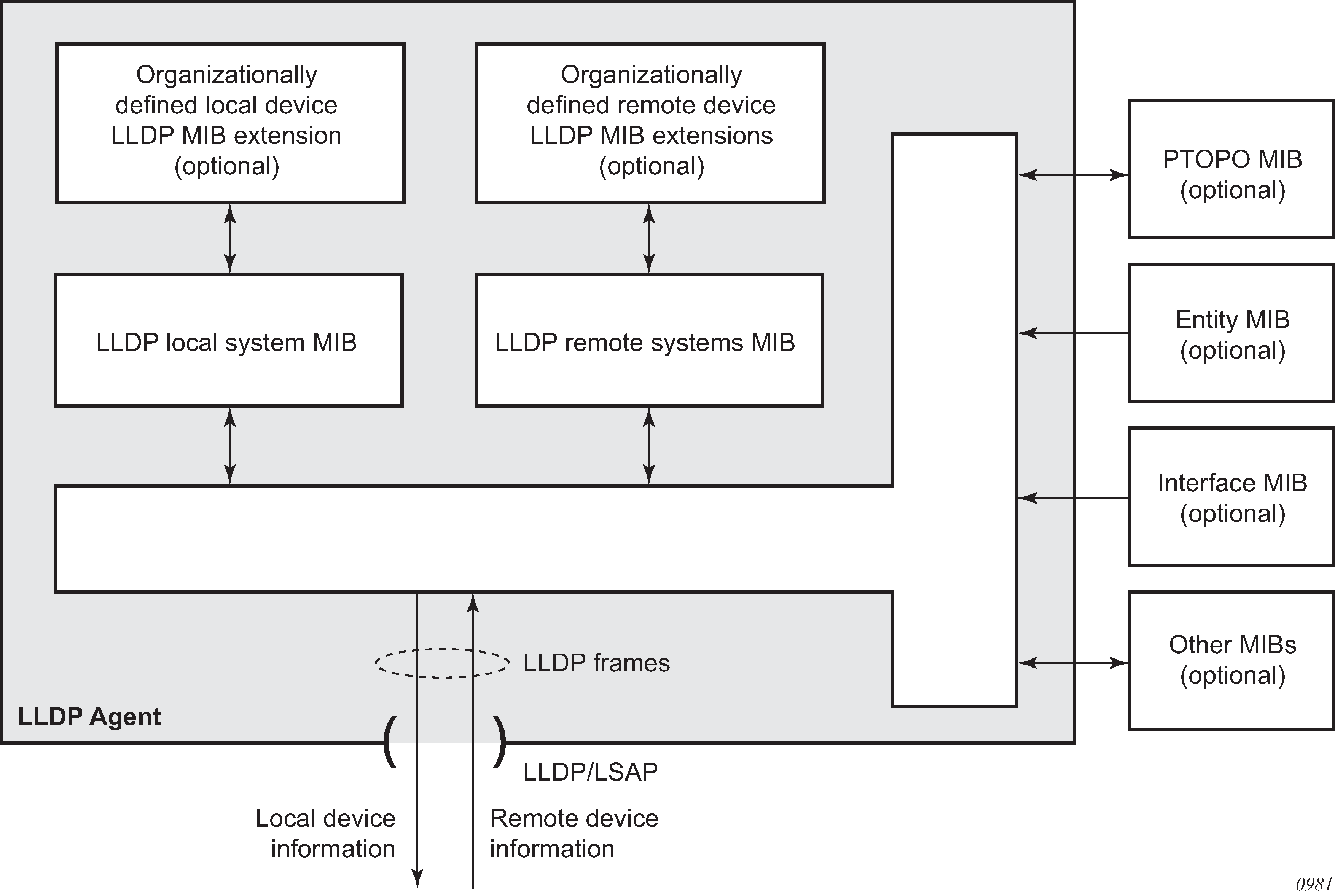
Network operators must be able to discover the topology information to detect and address network problems and inconsistencies in the configuration. Moreover, standard-based tools can address the complex network scenarios where multiple devices from different vendors are interconnected using Ethernet interfaces.
The example displayed in Customer use example for LLDP depicts a MPLS network that uses Ethernet interfaces in the core or as an access/hand off interfaces to connect to different kind of Ethernet enabled devices such as service gateway/routers, QinQ switches, DSLAMs or customer equipment.
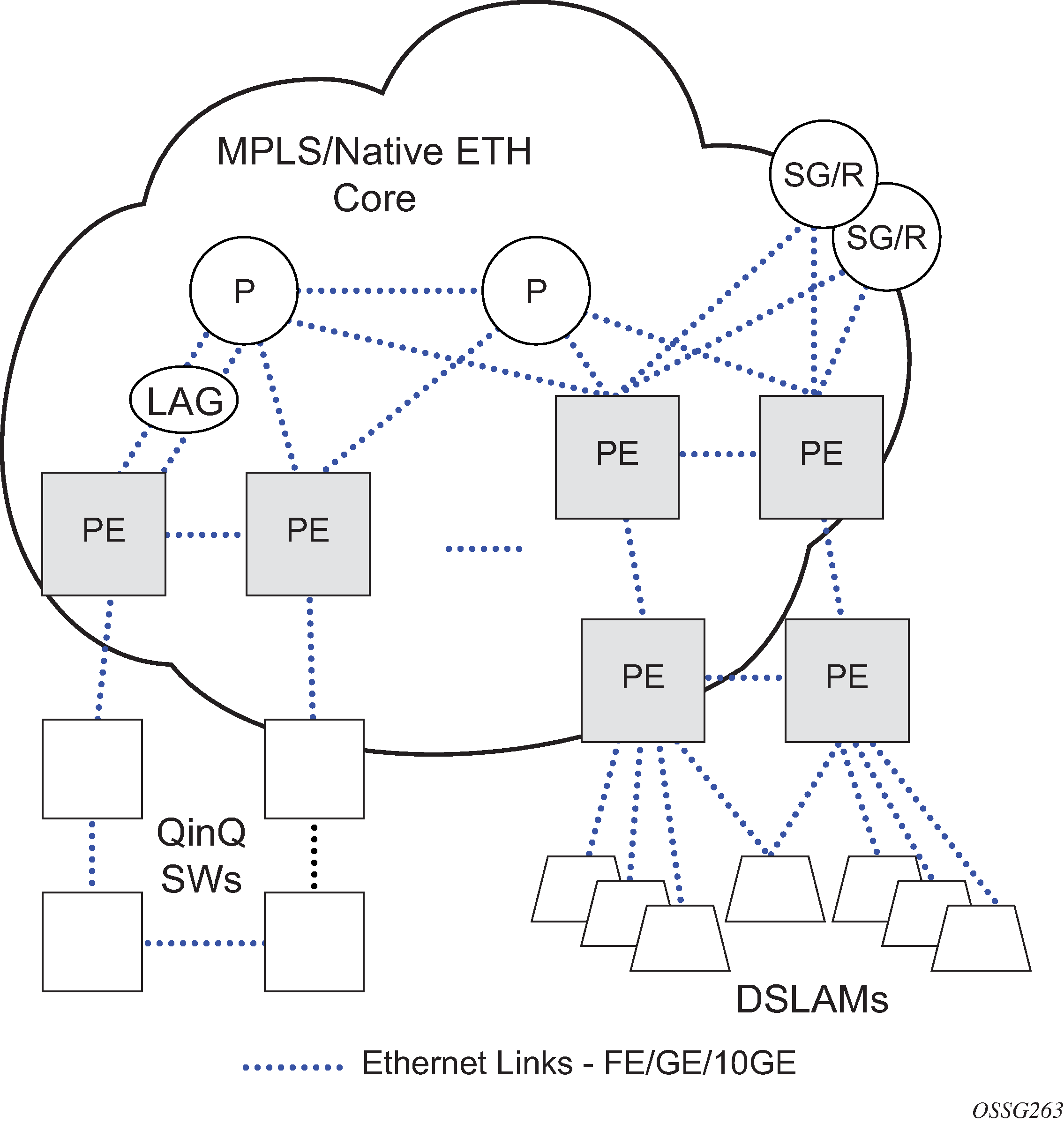
IEEE 802.1ab LLDP running on each Ethernet interfaces in between all the above network elements may be used to discover the topology information.
IP hashing as an LSR
It is now possible to include IP header in the hash routine at an LSR for the purpose of spraying labeled-IPv4 and labeled-IPv6 packets over multiple equal cost paths in ECMP in an LDP LSP and over multiple links of a LAG group in all types of LSPs.
A couple of configurable options are supported. The first option is referred to as the Label-IP Hash option and is designated in the CLI as lbl-ip. When enabled, the hash algorithm parses down the label stack and after it hits the bottom of the stack, it checks the next nibble. If the nibble value is four or six then it assumes it is an IPv4 or IPv6 packet. The result of the hash of the label stack, along with the incoming port and system IP address, is fed into another hash along with source and destination address fields in the IP packet's header. The second option is referred to as IP-only hash and is enabled in CLI using ip-only. It operates the same way as the Label-IP Hash method except the hash is performed exclusively on the source and destination address fields in the IP packet header. This method supports both IPv4 and IPv6 payload and operates on packets received on an IP interface on an IOM3-XP/IMM port only.
By default, MPLS packet hashing at an LSR is based on the whole label stack, along with the incoming port and system IP address. This method is referred to as the Label-Only Hash option and is enabled by entering lbl-only.
configure system load-balancing lsr-load-balancingSatellites
There are two types of SAS-Sx satellites supported on the 7750 SR:
Ethernet satellites
TDM satellites
The following primary tasks must be performed to configure a satellite.
Create a software repository that specifies where the SAS-Sx should obtain its correct software image.
Create an Ethernet or TDM satellite association that binds a chassis to a set of uplinks and a software repository.
Configure the satellite ports to specify port configuration and service association.
Ethernet satellites
The Ethernet satellite support feature allows a 7210 SAS-Sx or SAS-S or 7250 IXR-X1/Xs and IXR-E-Ax chassis to act as a port extension for the 7750 SR host. In this configuration, all configuration and management functions are performed through the host node. Management of the satellite node is not required when it is configured in an Ethernet satellite operations mode. A direct, non-switched, Ethernet connection between the 7750/7950 host and the Ethernet satellite must be provided. The use of active Layer 2 switching devices in the path between the host and satellite is not supported.
Supported 7210 SAS Ethernet satellite chassis lists the supported Ethernet satellite chassis.
| Chassis type | Sat-type string |
|---|---|
|
7210 SAS-Sx 24-port fiber |
es24-1gb-sfp |
|
7210 SAS-Sx 48-port fiber |
es48-1gb-sfp |
|
7210 SAS-S 24F4SFP+ |
es24-sass-1gb-sfp |
|
7210 SAS-S 48F4SFP+ |
es48-sass-1gb-sfp |
|
7210 SAS-Sx 24-port copper 7210 SAS-S 24-port copper |
es24-1gb-tx |
|
7210 SAS-Sx 48-port copper 7210 SAS-S 48-port copper |
es48-1gb-tx |
|
7210 SAS-Sx 24-port copper + PoE 7210 SAS-S 24-port copper + PoE |
es24-1gb-tx |
|
7210 SAS-Sx 48-port copper + PoE 7210 SAS-S 48-port copper + PoE |
es48-1gb-tx |
|
7210 SAS-Sx 64-port 10GE (CFP) |
es64-10gb-sfpp+4-100gb-cfp4 |
|
7210 SAS-Sx 64-port 10GE + 4-port QSFP28 |
es64-10gb-sfpp+4-100gb-qsfp28 |
|
7210 SAS-Mxp |
es24-sasmxp-1gb-sfp |
| Chassis type | Sat-type string |
|---|---|
| 7250 IXR-Xs | es6-qsfpdd+48-sfp56 |
| 7250 IXR-X1 | es32-qsfp28+4-qsfpdd |
| 7250 IXR-E-Ax | es24-sfpp+8-sfp28+2-qsfp28 |
-
The 7210 SAS-Sx 64-port 10GE Ethernet satellite supports both 10GE and 1GE optics. See the 7210 Optics Guide for a list of supported modules.
-
The 64x10GE + 4xQSFP28 SAS-Sx and IXR satellites do not support the local-forwarding feature.
-
The 7210 SAS-Mxp does not support the local forwarding feature.
-
PoE functionality is not supported when the 7210 PoE capable switches are used in satellite mode.
-
For traffic sent by the 7750 SR or 7950 XRS host to the 7210 SAS satellite, the satellite Q-tag P-bits and DEI bits are set based on the forwarding class and profile associated with the traffic through the 7750 SR or 7950 XRS system.
TDM satellites
The SONET/SDH ETR chassis is the only available TDM satellite and can be configured for different modes. Supported SONET/SDH satellite chassis lists the supported modes of the satellite chassis.
| Chassis type | Sat-type string |
|---|---|
4 port OC3 |
ts4-choc3-sfp |
4 port STM1 |
ts4-chstm1-sfp |
1 port OC12 |
ts1-choc12-sfp |
1 port STM4 |
ts1-chstm4-sfp |
The default type on a supplied TDM satellite is ts4-choc3-sfp. Updating to another type initiates a reboot of the satellite.
The TDM satellite provides CEM functionalities supported on the 7750 SR OC3/OC12 CES MDAs. The satellite is built using the same architecture as the 7705 SAR-8 adapter cards and is designed to transport existing TDM services including:
Cpipe service of DS1/E1 channels within SONET/SDH in structure-agnostic mode (SATOP) as described in RFC4553
MEF8 service of DS1/E1 channels within SONET/SDH in structure-agnostic mode
The following types of synchronization are supported:
DS1/E1 channels can be independently loop-timed, node-timed, or differentially-timed
OC3/STM1/OC12/STM4 ports can be node-timed
To provide a stable frequency from the host to the SONET/SDH satellite, ensure that the host's clock is referenced to a suitable timing source (for example, BITS) and configure Synchronous Ethernet from the host's Ethernet port connecting to the satellite. Copper Ethernet SFPs are not supported because they do not support Synchronous Ethernet.
The TDM satellite is entirely managed through a 7750 SR host system, such as 7750 SR, 7750 SR-a, or 7750 SR-e. As a satellite, no new IP address needs to be assigned. Services on the satellite are configured on the host in the same manner as any ports in a native MDA. The TDM satellite connects to the SR host using a Gigabit Ethernet link, thereby not occupying valuable slots space in the host system. APS is supported across satellites connecting to a single host.
Software repositories for satellites
The software repositories define the locations from where the host can obtain software for subcomponents including Ethernet satellites. The software repository is also used to upgrade an existing subcomponent by changing the location of the image to be served to the remote device. The software repositories are not used for management of the host router software, which is managed using the standard procedures described in the SR OS R22.x.Rx Software Release Notes.
Each software repository supports up to three locations to search for the software. A location may be a URL or a directory on a compact flash. When an upgrade operation is initiated, each of the three locations is checked in sequence to locate the required software. The upgrade operation fails if the software is not located in any of the configured locations. The satellite booting operation also fails if the software cannot be located.
At least one software repository must be configured to support a satellite connected to the local host as follows:
- Create a software repository using a unique repository name.
- Specify the primary location for the SAS/IXR image.
- Optionally, specify a secondary or tertiary image location and a description:
- MD-CLI
configure system software-repository
configure satellite ethernet-satellite software-repository
Note: First configure the software repository in the system context and then reference it in the satellite software-repository context. - classic
CLI
configure system software-repository
configure system satellite eth-sat software-repository
Upgrading satellite software
- Copy the new satellite software images to a local compact flash card. It is
recommended that the new image files be placed in a different directory.
Although you can store the satellite software on a remote server and use a URL to reference the remote location, it is recommended that the primary image location is locally accessible.
- Create a new software repository using a new name and at least a primary-location for the 7210 SAS/7250 IXR image.
-
Use the following contexts to modify the satellite configuration
such that the software-repository references the newly
created software repository.
- MD-CLI
configure satellite ethernet-satellite - classic
CLI
configure system satellite eth-sat
- MD-CLI
-
Reboot the satellite to load the new software. Depending on whether
a firmware update is needed, perform one of the following steps to reboot the
satellite.
- If a satellite firmware update is not required:
-
The satellite loads the new software the next time it reboots.
-
If required, use the following administrative command to reset the satellite:
- MD-CLI
admin satellite ethernet-satellite reboot now - classic
CLI
admin satellite eth-sat reboot now
- MD-CLI
-
- If a satellite firmware update is required:
-
Use one of the following commands to continue the upgrade to the 7210 firmware image and allow it to execute completely:
- MD-CLI
admin satellite ethernet-satellite synchronize - classic
CLI
admin satellite eth-sat sync-boot-env
- MD-CLI
-
Use the following command to reboot the satellite to update the firmware image. This causes the 7210 SAS-Sx to upgrade the included firmware images. This process takes longer than a normal reboot.
- MD-CLI
admin satellite ethernet-satellite reboot upgrade - classic
CLI
admin satellite eth-sat reboot upgrade now
- MD-CLI
-
- If a satellite firmware update is not required:
Synchronization features with satellites
See Synchronization with Ethernet satellites for restrictions on SyncE and PTP when using satellites.
Satellite configuration
After creating the software repositories, configure the satellite. The satellite configuration is required to create a satellite binding to a satellite ID, and to provide more information that uniquely identifies the satellite chassis, chassis type, and the software repository to be used to boot the remote satellite.
The following can be specified for a satellite:
MAC address
The satellite chassis MAC address must be specified. This is used to bind a specific chassis to the associated satellite ID. (The local host router boots only satellites with configured MAC addresses.) This is mandatory.
satellite type
The satellite chassis type must be specified and must match the chassis type that the satellite advertises during the boot process. This is mandatory.
software repository
A preconfigured software repository must be specified in the satellite configuration. This defines the location of the software image to boot the associated 7210 SAS-Sx. This is mandatory.
enabled state
By default, a new satellite is in the disabled state and must be administratively enabled. This is mandatory.
description
Configure an optional description string associated with the satellite.
sync-e
Enable sync-e for an Ethernet satellite.
Satellite client port ID formats
When referencing satellite ports, always use 1 for the slot number.
Use the following format to reference Ethernet satellite client ports:
port esat-sat-id/1/portNumReference Ethernet satellite client ports
port esat-4/1/2Use the following format to reference Ethernet satellite uplink ports:
port esat-sat-id/1/uportNumReference Ethernet satellite uplink ports
port esat-5/1/u2In the classic CLI, use the following format to reference TDM satellite client ports:
port tsat-sat-id/1/portNum.channelReference TDM satellite client ports
port tsat-3/1/4.1In the classic CLI, use the following format to reference TDM satellite uplink ports:
port tsat-sat-id/1/uport.channelReference TDM satellite uplink ports
port tsat-4/1/u1.1Ethernet satellite client ports support all port modes (access, network, and client).
Configuring services associated with satellite client ports is the same as configuring services on local 7750 SR ports, except that satellite client ports are referenced with the syntax for the Ethernet satellite port described above. It is required that a port-scheduler-policy is created to ensure that the 7750 SR is able to shape the traffic for the egress satellite port type and speed.
Local forwarding
The local forwarding capability allows traffic to be forwarded between two client satellite ports without going through the SR host, which allows for optimal forwarding by preserving uplink bandwidth.
Locally forwarded traffic is identified based on the ingress VLAN tag.
The outer VLAN tag used to identify the traffic to be locally forwarded can be different at the two bypass endpoints. In that case, as traffic is forwarded from the ingress to the egress, the outer VLAN tag is modified.
The bypass paths are bidirectional, so only a single local-forwarding path needs to be defined to allow for traffic flow in both directions.
Local forwarding shows an example of local forwarding.
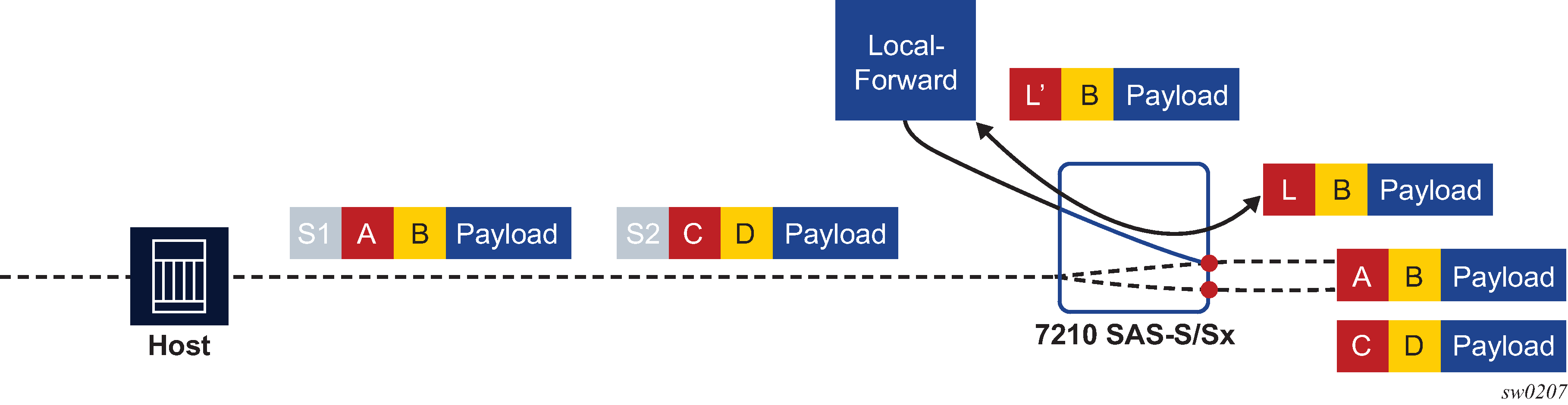
A local-forward bypass is created by using the following commands to create a local-forward bypass, then associating a set of two satellite access points as endpoints for the local-forward bypass.
The two endpoints must be ports on the same Ethernet satellite chassis.
If a LAG is used as an endpoint, all member links must be ports on the same Ethernet satellite.
All satellite ports must be client ports by default, or must be configured as a client port using the port-template command.
The following example shows the commands to configure a local-forward bypass between client ports esat-2/1/1:66 and esat-2/1/50:101.
MD-CLI
[ex:/configure satellite]
A:admin@node-2# info
    ethernet-satellite 10 {
        admin-state enable
        description "local-forward to offload router"
        port-map esat-2/1/1 {
        }
        port-map esat-2/1/50 {
        }
    }
classic CLI
A:node-2>config>system>satellite# info
----------------------------------------------
          local-forward 10 create
               description "local-forward to offload router"
               sap esat-2/1/1:66 create
               exit
               sap esat-2/1/50:101 create
               exit
               no shutdown
          exit
----------------------------------------------
Port template
The port-template command hierarchy allows the creation of a satellite template that reconfigures the port role and uplink association for one or more satellite ports. This template can then be applied to one or more Ethernet satellite instances, in which case those satellites inherit the specified port role and uplink associations.
The port template is necessary when reconfiguring a satellite uplink as a client port for use as part of a local-forward bypass path. Use the following command to create satellite templates:
- MD-CLI
configure satellite port-template - classic
CLI
configure system satellite port-template
7210 SAS 10GE client ports
Ports 51 and 52 on the 48xGE + 4x10GE satellite chassis can be reassigned as client ports instead of uplink ports. This provides the flexibility to offer 10GE services from these satellite chassis. These two 10GE ports can be reconfigured as client ports using the port-template configuration commands described above. The port template configuration must be done before SAPs, interfaces, or services can be applied to the associated satellite ports.
7210 SAS 100GE client ports
Ports 67 and 68 on the 64x10GE + 4x100GE satellites (sat-type es64-10gb-sfpp+4-100gb-cfp4) and connectors 3 and 4 on the 64x10GE+4xQSFP28 (sat-type es64-10gb-sfpp+4-100gb-qsfp28) can be reassigned as client ports instead of uplinks. This provides the flexibility to offer 100GE services from these satellite chassis. These two 100GE ports can be reconfigured as client ports using the port-template configuration commands. The port template must be configured before port topology bindings are configured as well as before SAPs, interfaces, or services can be applied to the associated satellite ports.
10GE uplinks on the 64x10GE+4x100GE satellite
On the 7210 SAS-Sx 64x10GE+4x100GE (es64-10gb-sfpp+4-100gb-cfp4) and 64x10GE+4xQSFP28 (sat-type es64-10gb-sfpp+4-100gb-qsfp28) satellite, selected 10GE ports can be reconfigured and used as satellite uplinks to the host router running SR OS.
Up to 16 10GE interfaces can be used as uplinks for the associated satellite. You must create a new satellite template that configures the needed 10GE interfaces as uplinks. In addition, use a port template to specify the uplink association between the remaining client ports and configured uplinks.
Apply the new template to the satellite using the template-name command, where the template-name is the name configured in the port-template context.
This feature requires the 7210 SAS-Sx to be running Release 9.0.R10 or later for the SAS-Sx 64x10GE+4x100GE and 7210 SAS Release 10.0 or later for the 64x10GE+4xqSFP28 satellite.
The following restrictions apply:
The 10GE ports used as satellite uplinks must start at port 1 and be sequential, up to the maximum of 16 10GE uplinks.
When 10GE ports are used as uplinks, the 4x100GE port are not available for use and should be configured as role none.
The following example shows the configuration.
MD-CLI
[ex:/configure satellite]
A:admin@node-2# info
    port-template "10gUp" {
        admin-state enable
        sat-type es64-10gb-sfpp+4-100gb-cfp4
        port "1/1/1" {
            role uplink
        }
        port "1/1/2" {
            role uplink
        }
        port "1/1/3" {
            role uplink
        }
        ...
        port "1/1/9" {
            uplink 1/1/1
        }
        port "1/1/10" {
            uplink 1/1/1
        }
        ...
        port "1/1/16" {
            uplink 1/1/2
        }
        port "1/1/17" {
            uplink 1/1/2
        }
        port "1/1/65" {
            role none
        }
        port "1/1/66" {
            role none
        }
        ...
    }
    ethernet-satellite 20 {
        admin-state enable
        mac-address d0:99:d5:96:ee:41
        sat-type es64-10gb-sfpp+4-100gb-cfp4
        software-repository rep1
        port-template "10gUp"
    }
classic CLI
A:node-2>config>system>satellite# info
----------------------------------------------
          port-template "10gUp" sat-type "es64-10gb-sfpp+4-100gb-cfp4" create
               port 1/1/1
                    role uplink
                    uplink none
               exit
               port 1/1/2
                    role uplink
                    uplink none
               exit
               port 1/1/3
                    role uplink
                    uplink none
               exit
               ...
               port 1/1/9
                    uplink 1/1/1
               exit
               port 1/1/10
                    uplink 1/1/1
               exit
               ...
               port 1/1/16
                    uplink 1/1/2
               exit
               port 1/1/17
                    uplink 1/1/2
               exit
               ...
               port 1/1/65
                    role none
               exit
               port 1/1/66
                    role none
               exit
               ...
               no shutdown
          exit
          eth-sat 20 create
               mac-address d0:99:d5:96:ee:41
               sat-type "es64-10gb-sfpp+4-100gb-cfp4"
               port-template "10gUp"
               software-repository "rep1"
               no shutdown
          exit
----------------------------------------------
Satellite uplink resiliency
An option in the port-map configuration allows a secondary uplink to be assigned to enable uplink resiliency. A secondary uplink is used to carry the traffic associated with the client port if the primary uplink becomes unavailable. If traffic is switched to the secondary uplink, when the primary uplink becomes available, traffic is reverted to the primary as soon as possible.
Use the following command to configure a secondary uplink per client port:
- MD-CLI
configure satellite ethernet-satellite port-map secondary - classic
CLI
configure system satellite eth-sat port-map secondary
To configure a secondary uplink, after the primary uplink is specified, the secondary keyword should be included, followed by the intended uplink to be used as the secondary uplink.
MD-CLI
[ex:/configure satellite]
A:admin@node-2# info
     ethernet-satellite 1 {
          port-map esat-1/1/2 {
               primary esat-1/1/u1
               secondary esat-1/1/u3
          }
     }
classic CLI
A:node-2>config>system>satellite# info
----------------------------------------------
          eth-sat 1 create
               port-map esat-1/1/2
               primary esat-1/1/u1
               secondary esat-1/1/u3
          exit
-----------------------------------------------
If there are no SAPs or interfaces bound to a client port, then any change can be made to the uplinks.
-
If a SAP or interface is bound to a client port, or the client port is member of a LAG or ETH tunnel, then only one uplink change per configuration command is allowed (see below).
-
The primary cannot be changed directly, this requires multiple steps.
-
swap primary and secondary
-
remove secondary
-
add new secondary
-
do a second swap of primary and secondary
-
The following are basic actions allowed with a single command:
-
add or delete secondary uplink
-
swap primary and secondary
-
add a secondary uplink and swap secondary with primary
Uplink mapping can be changed, but a client uplink must be maintained throughout the process. For example, client-10 is mapped to uplink-1 (U-1), but must move to uplink-2 (U-2). To do this, add U-2 as the secondary uplink, then swap the primary and secondary, making U-2 the primary uplink for client-10 and switching traffic to U-2. After the switch is complete, remove U-1. U-1 cannot be directly replaced with U-2, as the client port would have no uplink during the switch.
Dynamic uplink resiliency
The host system can use the dynamic uplink resiliency mechanism to automatically manage uplink resiliency assignments. Through this mechanism, the host dynamically assigns a primary and secondary uplink for each satellite access port. Depending on the configuration options specified, the uplinks (primary and secondary) can be distributed over one or two FP forwarding engines.
Uplink distribution behavior
When using dynamic uplink resiliency, the primary and secondary uplink assignments are re-evaluated each time an uplink on a satellite becomes operationally up. This is done to rebalance uplink assignments for optimal distribution. The secondary uplink assignment is also re-evaluated each time an uplink on a satellite goes operationally down.
Uplinks are assigned to achieve fair distribution based on the following criteria:
-
FP distribution
-
MDA distribution
-
connector distribution
This feature requires that the Ethernet satellite is running 7210 SR OS 20.9.R1 or later.
Basic configuration
The following example shows dynamic uplink resiliency configuration.
MD-CLI
[ex:/configure satellite]
A:admin@node-2# info
    ethernet-satellite 1 {
        admin-state enable
        sat-type es48-1gb-sfp
        dynamic-uplink true
        uplink-distribution dual-complex
    }
classic CLI
A:node-2>config>system>satellite# info
----------------------------------------------
          eth-sat 1 create
               sat-type es48-1gb-sfp
               dynamic-uplink true
               uplink-distribution dual-complex
               no shutdown
          exit
----------------------------------------------
Ethernet LAGs with satellite member links
Ethernet LAGs can use a mixture of physical Ethernet ports (including connector-based ports) and satellite access ports. However, satellite access ports are not supported within mixed speed LAGs.
Auto-provisioning
Auto-provisioning is used to provision a node using an external DHCP server and file server. It is used to obtain a configuration file and an image file from an external server using an in-band mechanism. Auto-provisioning is not compatible with an out-of-band management port.
Before using auto-provisioning, the SR OS must be booted up and running the application image. In addition, it needs to have some minimum configuration before the auto-provision script is executed by the operator.
After the auto-provision application is triggered using a tools command, SR OS checks all operationally up ports without IP addresses and send DHCP discovery to these interfaces. The DHCP server needs to be configured with Option 67 and the user must provide the SR OS with the URL of a file server and the corresponding directory for the image.
Example of a network with no DHCP relay to Example of a network with multiple subnets describe scenarios in which auto-provisioning are used.
In Example of a network with no DHCP relay, there is no DHCP relay and all IP addresses are assigned from a single pool.
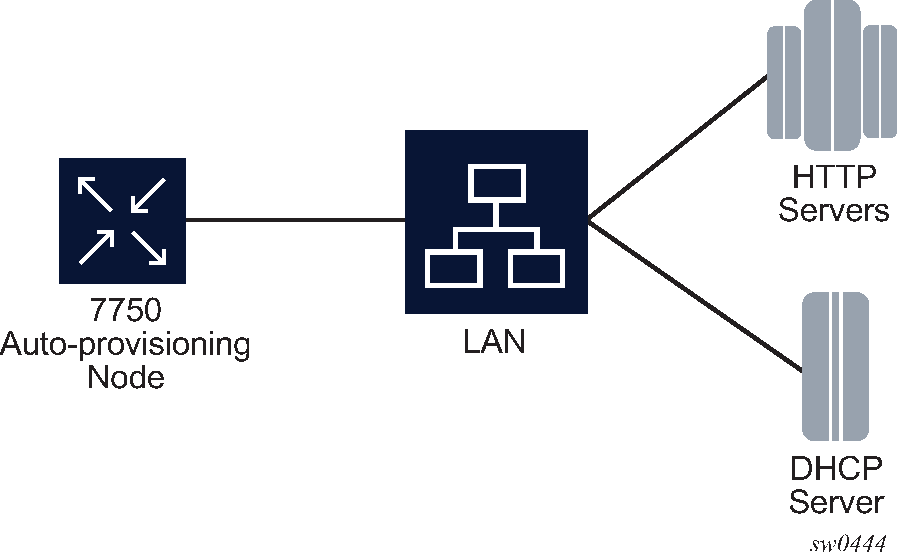
In Example of a network with a DHCP relay, there is a DHCP relay which injects the Option 82 as a gateway address. The DHCP server is assigned the IP address from the pool dictated by the gateway address option 82. The DHCP server and HTTP server are in the same subnet. The DHCP offer has option 3 "router" which is used for a default gateway creation on the 7750 SR.
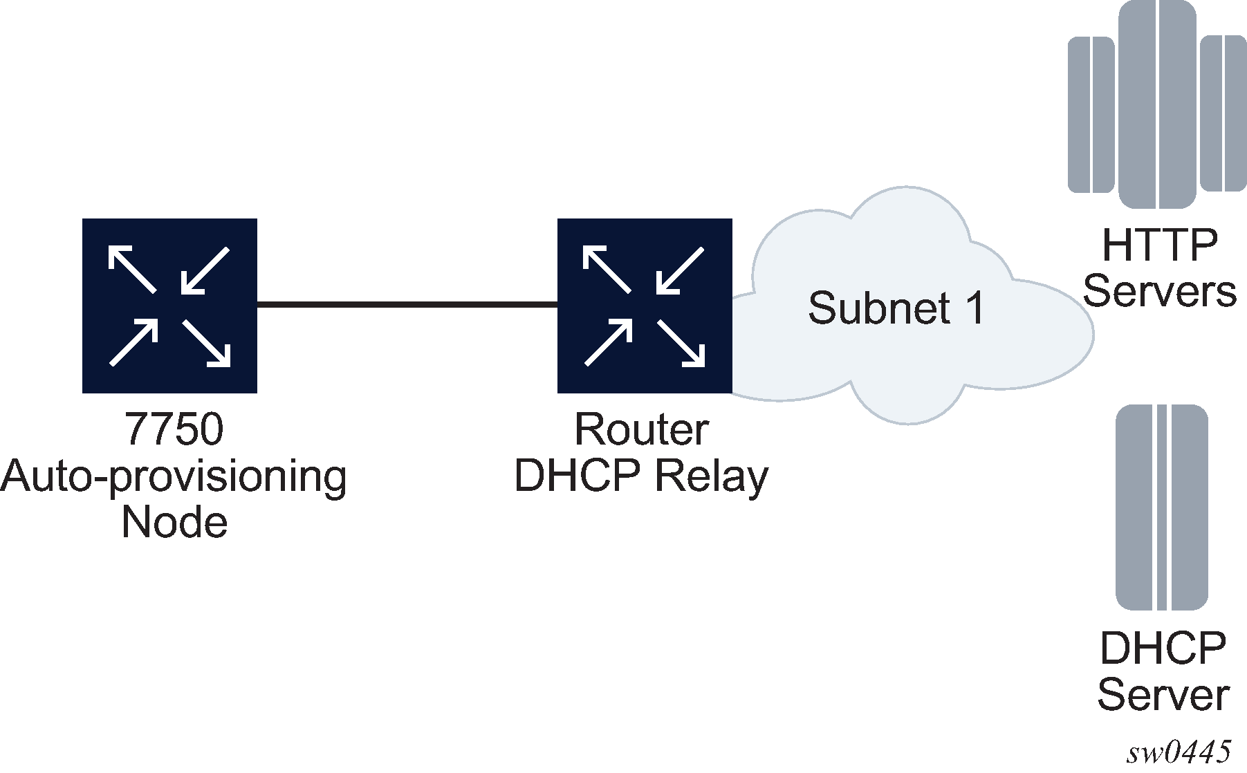
In Example of a network with multiple subnets, all components are in different subnets. The DHCP relay adds Option 82 to the DHCP request as the gateway address which is used for pool selection. The DHCP server must add option 3 configured with the gateway address of the HTTP server.
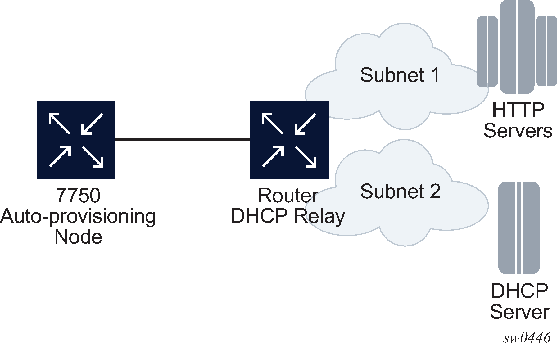
Auto-provisioning limits
The following are some configuration limits for auto-provisioning:
A maximum of 12 Layer 3 interfaces are supported for auto-provisioning.
Only IPv4 auto-provisioning is supported.
It is highly recommended to only have a basic card, MDA, port, and interface configuration as described in this document and no additional static routes or IGP or BGP protocols when performing auto-provisioning because auto-provisioning installs default static routes that may be affected by any extra routing configuration.
A maximum of 255 characters is supported for the remote URL (200 character maximum for the filepath, the rest for the main URL consisting of the protocol, login credentials, and host IP). A maximum of 200 characters is supported for the local URL. The local file or folder name must not exceed 99 characters.
The maximum number of file pairs for each image/config record is 10.
Auto-provisioning process
In this process, the node detects operational ports, attempts to discover its IP address, and downloads the relevant files for provisioning.
The node sends a DHCP discovery request to the DHCP server using the out-of-band management port. If DHCP discovery is unsuccessful, the node reattempts it using the in-band management ports.
After DHCP discovery is successful, the DHCP server returns an IPv4 or IPv6 FTP or HTTP URL of a file server from which the node can retrieve provisioning information.
The node downloads the provisioning information and performs the auto-provisioning according to the specifications in the files.
After the node is successfully provisioned, it automatically reboots and becomes operationally up.
See Provisioning files for more information about the auto-provisioning process.
The SR OS can also initiate the auto-provisioning process using a tools command.
Auto-provisioning DHCP rules
The following are the DHCP rules in the auto-provisioning stage:
First, auto-provisioning walks through the interfaces with a configured port, where the port is in operational status up, one by one.
It sends a DHCP request to the first configured interface with a port up and no IP address configured.
-
If, on this interface, multiple DHCP offers arrives, only the first offer is sent to the auto-provisioning task and the other offers are ignored. This could occur if the node is on a LAN and multiple DHCP servers are connected to the interface.
-
The DHCP client has an exponential retry mechanism. If the DHCP offer does not arrive from the server, the client resends a DHCP request at 2, 4, 8, 32 and 64 s, with 64 s being the maximum timeout, If the 64 s timeout interval is reached, the DHCP client keeps retrying every 64 s. The user can configure a timeout value. If no DHCP offer has arrived by this timeout value, the auto-provisioning process moves to the next interface.
-
If the DHCP offer arrives on the port and the DHCP client task does not acknowledge the DHCP offer, for any reason, it disables the DHCP client and remove the IP from the port.
-
If the DHCP offer arrives on the port and the DHCP client acknowledges the offer, it sends the information to auto-provisioning. If auto-provisioning does not like the offer, because there is no Option 67, Option 67 is malformed, or for any other reason listed in Auto-provisioning failure, the auto-provisioning process deconfigures the DHCP client and the DHCP client sends a DHCP release, and unassigns the IP address.
-
In case of failure, more information is displayed by the auto-provisioning process and the process moves to the next port that is up and does not have an IP address.
-
If auto-provisioning is successful using the offer and its option, the provisioning file download starts though the protocol dictated by Option 67.
The auto-provisioning command is CLI blocking. All information about the auto-provisioning process is displayed on the CLI and logged.
Auto-provisioning failure
Auto-provisioning fails for the following reasons:
There is no Option 67.
The Option 67 format is not acceptable to auto-provisioning.
The format is a URL or DNS is not supported. There is a failure in the download provisioning file or the server is not reachable.
There is failure in the download of the image or config file using the provisioning file information, for example, the server is not available, the wrong directory is listed, or the wrong credentials are given.
The image or config fails to copy to the compact flash.
The image or config fails to sync to the inactive CPM.
The BOF does not point to the compact flash, for example, it is pointing to the network.
If the auto-provisioning procedure on this interface fails, then auto-provisioning does the following:
Displays information about the blocked CLI and in the log, describing the failure in detail.
Updates the DHCP task so the DHCP task can take the appropriate actions to release the IP address on the interface. This is done by sending a DHCP release for the DHCP ack received from the server.
Goes to the next interface with port up and no IP address.
Note: If no other interface with port up is found, the auto-provisioning task stops and a failure error is displayed on the CLI and in the log.
Administrative tasks
This section contains information to perform administrative tasks.
Saving configurations
Whenever configuration changes are made, the modified configuration must be saved so they are not lost when the system is rebooted.
Configuration files are saved by executing explicit command syntax which includes the file URL location to save the configuration file as well as options to save both default and non-default configuration parameters. Boot option file (BOF) parameters specify where the system should search for configuration and image files as well as other operational parameters during system initialization.
For more information about boot option files, see the Boot Options section.
Specifying post-boot configuration files
Two post-boot configuration extension files are supported and are triggered when either a successful or failed boot configuration file is processed. The boot-bad-exec and boot-good-exec commands specify URLs for the CLI scripts to be run following the completion of the bootup configuration. A URL must be specified or no action is taken.
For example, after a configuration file is successfully loaded, the specified URL can contain a nearly identical configuration file with specific commands enabled or disabled, or particular parameters specified and according to the script which loads that file.
Network timing
In Time Domain Multiplexed (TDM)-based networks (for example, SONET or SDH circuit- switched networks), the concept of network timing is used to prevent over-run or under-run issues where circuits are groomed (rebundled) and switched. Hardware exists in each node that takes a common clock derived from an internal oscillator, a specific receive interface, or special BITS interface and provides it to each synchronous interface in the system. Usually, each synchronous interface is allowed to choose between using the chassis-provided clock or the clocking recovered from the received signal on the interface. The clocking is used to drive the transmit side of the interface. The appropriate configuration at each node which defines how interface clocking is handled must be considered when designing a network that has a centralized timing source so each interface is operating in a synchronous manner.
The effect of timing on a network is dependent on the nature of the type of traffic carried on the network. With bit-wise synchronous traffic (traditional circuit-based voice or video), non-synchronous transmissions cause a loss of information in the streams affecting performance. With packet-based traffic, the applications expect and handle jitter and latency inherent to packet-based networks. When a packet-based network is used to carry voice or video traffic, the applications use data compression and elasticity buffering to compensate for jitter and latency. The network itself relies on appropriate Quality of Service (QoS) definitions and network provisioning to further minimize the jitter and latency the application may experience.
Power supplies
SR OS supports a power-supply command to configure the type and number of power supplies present in the chassis. The operational status of a power source is always displayed by the LEDs on the Control Processor/Switch Fabric Module (CP/SFM) front panel, but the power supply information must be explicitly configured in order for a power supply alarm to be generated if a power source becomes operationally disabled.
Automatic synchronization
Use the CLI syntax displayed below to configure synchronization components relating to active-to-standby CPM switchover. In redundant systems, synchronization ensures that the active and standby CPMs have identical operational configuration, including the active configuration, CPM, XCM, and IOM images in the event of a failure or reset of the active CPM.
The force-switchover command forces a switchover to the standby CPM card.
You can configure automatic synchronization to occur when the admin save or bof save commands are executed.
When boot-env is specified, the bof.cfg, primary/secondary/tertiary configuration files (.cfg and .ndx), li, and SSH files are automatically synchronized. When config is specified, only the configuration files are automatically synchronized.
Synchronization also occurs whenever the BOF is modified and when an admin save command is entered with no filename specified.
Boot-env option
The boot-env option enables a synchronization of all the files used in system initialization.
When configuring the system to perform this synchronization, the following occurs:
The BOF used during system initialization is copied to the same compact flash on the standby CPM (in redundant systems). The synchronization options on the standby CPM are preserved.
The primary, secondary, and tertiary images, (provided they are locally stored on the active CPM) are copied to the same compact flash on the standby CPM.
The primary, secondary, and tertiary configuration files, (provided they are locally stored on the active CPM) are copied to the same compact flash on the standby CPM.
Config option
The config option synchronizes configuration files by copying the files specified in the active CPM BOF file to the same compact flash on the standby CPM.
Both image files (CPM and IOM) on the 7450 ESS must be located in the same directory. Failure to locate and synchronize both images causes an error to be generated.
Manual synchronization
admin redundancy synchronizeForcing a switchover
The force-switchover now command forces an immediate switchover to the standby CPM card.
If the active and standby are not synchronized for some reason, users can manually synchronize the standby CPM by rebooting the standby by issuing the admin reboot command on the active or the standby CPM.
System router instances
SR OS supports multiple Layer 3 router instances. These instances have their own IP addressing spaces and configuration options. Router instances are isolated from each other.
The following are the different types of router instances in SR OS:
Base
All SR OS routers have the Base router instance: the system created default router instance used to forward user IP traffic among router line card ports. Router interfaces (that is, network interfaces configured under configure router [Base]) and IES services and interfaces exist in the Base router instance. The Base router instance is identified in SNMP as vRtrType = baseRouter (1) and has a vRtrID of 1.
VPRN instances
Another type of router instance is the set of operator configured VPRN services. Each VPRN service has a unique router instance. For more information about VPRN services and their associated router instances, see the 7450 ESS, 7750 SR, 7950 XRS, and VSR Layer 3 Services Guide: IES and VPRN. VPRN router instances are identified in SNMP as vRtrType = vprn (2), and the vRtrID is dynamically allocated.
Special system router instances
SR OS routers also support the following special router instances:
management
The management router instance is a system created router instance that is used for management of the router. The management router instance is bound to CPM/CCM ports A/1 and B/1. This is a CPM router instance which cannot be renamed or deleted by an operator. The management router instance is identified in SNMP as vRtrType = vr(3), and the vRtrID is 4095.
vpls-management
The vpls-management router instance is used for management of VPLS services. It is identified in SNMP as vRtrType = vr(3), and the vRtrID is 4094.
User created CPM router instances
User created CPM router instances are user defined router instances that are mainly used with Ethernet ports on the CPM/CCM cards: CPM router instances only use CPM/CCM Ethernet ports as interfaces. CPM router instances have a user-defined name and are the only types of non-VPRN router instances that can be created by the user. User created CPM router instances are identified in SNMP as vRtrType = vr(3), and the vRtrID is dynamically allocated.
Some management protocols can use either the base routing instance (in-band) or the management routing instance (out-of-band). A listing of these protocols can be found in the CPM Filter: Protocols and Ports section of the 7450 ESS, 7750 SR, 7950 XRS, and VSR System Management Guide. Unless otherwise stated in the detailed description of the protocol, when the server or client for the protocol is reachable via the management routing instance, those protocol messages use the management interface for the protocol communication.
If BOF is set up with autoconfiguration and the DHCP server provides a general default route such as 0.0.0.0/0, with some protocols (like PCEP, TACACS+, RADIUS, and LDAP), Authentication, Authorization, Accounting (AAA) always prefers OOB over in-band connectivity. This is because these protocols prefer to use the OOB management port first. If a matching route is not found, in-band is attempted. The static route provided by DHCP must be properly set to ensure the correct route preference is made by these protocols.
System configuration process overview
System configuration and implementation flow shows the process for basic system provisioning.
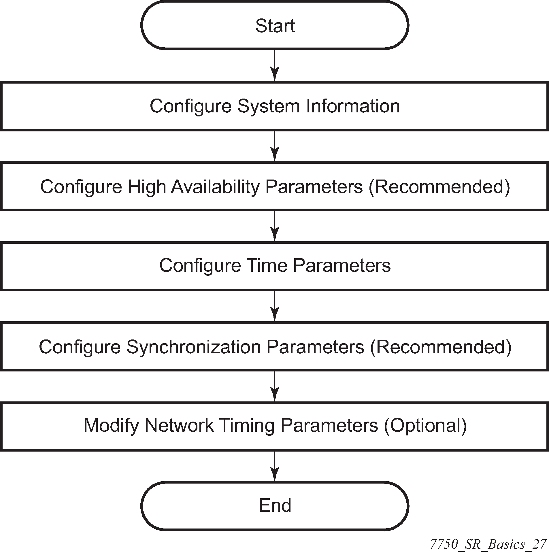
General configuration notes
To access the CLI, the system must be properly initialized and the boot loader and BOF files successfully executed.
Configuring system management features
This section provides information about configuring system management features.
Saving configurations
Whenever configuration changes are made, the modified configuration must be saved so the changes are not lost when the system is rebooted. The system uses the configuration and image files, as well as other operational parameters necessary for system initialization, according to the locations specified in the boot option file (BOF) parameters. For more information about boot option files, see Boot options.
Configuration files are saved by executing implicit or explicit command syntax.
An explicit save writes the configuration to the location specified in the save command syntax (the file-url option).
An implicit save writes the configuration to the file specified in the primary configuration location.
If the file-url option is not specified in the save command syntax, the system attempts to save the current configuration to the current BOF primary configuration source. If the primary configuration source (path and filename) changed after the last boot, the new configuration source is used.
The save command includes an option to save both default and non-default configuration (the detail option).
The index option specifies that the system preserves system indexes when a save command is executed, regardless of the persistent status in the BOF file. During a subsequent boot, the index file is read along with the configuration file. As a result, a number of system indexes are preserved between reboots, including the interface index, LSP IDs, path IDs, and so on. This reduces resynchronizations of the Network Management System (NMS) with the affected network element.
If the save attempt fails at the destination, an error occurs and is logged. The system does not try to save the file to the secondary or tertiary configuration sources unless the path and filename are explicitly named with the save command.
Basic system configuration
This section provides information to configure the system and provides configuration examples of common configuration tasks. The following is the minimal required system:
Use the following command to display basic system information such as the system name, platform type, and so on.
configure system informationCommon configuration tasks
This section provides a brief overview of the tasks that must be performed to configure the system and provides the CLI commands.
System information
This section covers the basic system information to configure the physical location of the router, contact information, location information (the place the router is located such as an address, floor, room number, and so on), global positioning system (GPS) coordinates, and system name.
System information configuration options
Name
You can configure a name for the system device. The name is used in the prompt string. Only one system name can be configured. If multiple system names are configured the last one encountered overwrites the previous entry. Use the following command to configure the system name.
configure system nameContact
Use the contact command to specify the name of a system administrator, IT staff member, or other administrative entity. Use the following command to configure the system contact.
configure system contactLocation
Use the location command to specify the system location of the device. For example, enter the city, building address, floor, room number, and so on, where the router is located. Use the following command to configure the system location.
configure system locationCLLI code
The Common Language Location Code (CLLI code) is an 11-character standardized geographic identifier that is used to uniquely identify the geographic location of an SR-series router. Use the following command to configure the CLLI code.
configure system clli-codeCoordinates
You can optionally configure the GPS location of the device. If the string contains special characters (#, $, spaces, and so on), the entire string must be enclosed within double quotes. Use the following command to configure the system coordinates.
configure system coordinatesSystem time elements
The system clock maintains time according to Coordinated Universal Time (UTC). Configure information time zone and summer time (daylight savings time) to correctly show the time according to the local time zone.
Zone
The zone command sets the time zone and time zone offset for the router. The router supports system-defined and user-defined time zones. The system-defined time zones are listed in System-defined time zones. Use the following command to configure the system time zone.
configure system time zone| Acronym | Time zone name | UTC offset |
|---|---|---|
Europe |
||
GMT |
Greenwich Mean Time |
UTC |
WET |
Western Europe Time |
UTC |
WEST |
Western Europe Summer Time |
UTC +1 hour |
CET |
Central Europe Time |
UTC +1 hour |
CEST |
Central Europe Summer Time |
UTC +2 hours |
EET |
Eastern Europe Time |
UTC +2 hours |
EEST |
Eastern Europe Summer Time |
UTC +3 hours |
MSK |
Moscow Time |
UTC +3 hours |
MSD |
Moscow Summer Time |
UTC +4 hours |
US and Canada |
||
AST |
Atlantic Standard Time |
UTC -4 hours |
ADT |
Atlantic Daylight Time |
UTC -3 hours |
EST |
Eastern Standard Time |
UTC -5 hours |
EDT |
Eastern Daylight Saving Time |
UTC -4 hours |
CST |
Central Standard Time |
UTC -6 hours |
CDT |
Central Daylight Saving Time |
UTC -5 hours |
MST |
Mountain Standard Time |
UTC -7 hours |
MDT |
Mountain Daylight Saving Time |
UTC -6 hours |
PST |
Pacific Standard Time |
UTC -8 hours |
PDT |
Pacific Daylight Saving Time |
UTC -7 hours |
HST |
Hawaiian Standard Time |
UTC -10 hours |
AKST |
Alaska Standard Time |
UTC -9 hours |
AKDT |
Alaska Standard Daylight Saving Time |
UTC -8 hours |
Australia and New Zealand |
||
AWST |
Western Standard Time (such as Perth) |
UTC +8 hours |
ACST |
Central Standard Time (such as Darwin) |
UTC +9.5 hours |
AEST |
Eastern Standard/Summer Time (such as Canberra) |
UTC +10 hours |
NZT |
New Zealand Standard Time |
UTC +12 hours |
NZDT |
New Zealand Daylight Saving Time |
UTC +13 hours |
Summer time coordinates
Configure the start and end dates and offset for summer time or daylight savings time to override system defaults or for user defined time zones. When configured, the time is adjusted by adding the configured offset when summer time starts and subtracting the configured offset when summer time ends. Use commands in the following context to configure summer time coordinates.
configure system time dst-zoneIf the time zone configured is listed in System-defined time zones, the starting, ending, and offset do not need to be configured with this command unless there is a need to override the system defaults. The command returns an error if the start and ending dates and times are not available either in System-defined time zones or entered as configuration options in this command.
NTP
NTP is the Network Time Protocol defined in RFC 1305, Network Time Protocol (Version 3) Specification, Implementation and Analysis and RFC 5905, Network Time Protocol Version 4: Protocol and Algorithms Specification. It allows for the participating network nodes to keep time more accurately and more importantly they can maintain time in a more synchronized fashion between all participating network nodes.
SR OS uses an NTP process based on a reference build provided by the Network Time Foundation. Nokia strongly recommends that the users review RFC 8633, Network Time Protocol Best Current Practices, when they plan to use NTP with the router. The RFC section ‟Using Enough Time Sources” indicates that using only two time sources (NTP servers) can introduce instability if they provide conflicting information. To maintain accurate time, Nokia recommends configuring three or more NTP servers.
NTP uses stratum levels to define the number of hops from a reference clock. The reference clock is considered to be a stratum-0 device that is assumed to be accurate with little or no delay. Stratum-0 servers cannot be used in a network. However, they can be directly connected to devices that operate as stratum-1 servers. A stratum-1 server is an NTP server with a directly-connected device that provides Coordinated Universal Time (UTC), such as a GPS or atomic clock.
The higher stratum levels are separated from the stratum-1 server over a network path, therefore, a stratum-2 server receives its time over a network link from a stratum-1 server. A stratum-3 server receives its time over a network link from a stratum-2 server.
SR OS routers normally operate as a stratum-2 or higher device. The router relies on an external stratum-1 server to source accurate time into the network. However, SR OS also allows for the use of the local PTP recovered time to be sourced into NTP. In this latter case, the local PTP source appears as a stratum-0 server and SR OS advertises itself as a stratum-1 server. Activation of the PTP source into NTP may impact the network NTP topology because the SR OS router is promoted to stratum-1.
SR OS router runs a single NTP clock which then operates NTP message exchanges with external NTP clocks. Exchanges can be made with external NTP clients, servers, and peers. These exchanges can be through the base, management, or VPRN routing instances.
NTP operates associations between clocks as either client or server, symmetric active and symmetric passive, or broadcast modes. These modes of operation are applied according to which elements are configured on the router. To run server mode, the operator must enable NTP server mode for the base and each needed VPRN routing instance. To run client mode, the operator must configure external servers. If both the local router and remote router are configured with each other as peers, then the router operates in symmetric active mode. If only one side of the association has peering configured, then the modes are symmetric passive. To operate using broadcast mode, interfaces must be configured to transmit as broadcast servers or receive as broadcast clients.
NTP server operation for both unicast and broadcast communication within a VPRN is configured within the VPRN (see the NTP Within a VPRN Service section in 7450 ESS, 7750 SR, 7950 XRS, and VSR Layer 3 Services Guide: IES and VPRN).
The following NTP elements are supported:
server mode
In this mode, the node advertises the ability to act as a clock source for other network elements. The node, by default, transmits NTP packets in NTP version 4 mode.
authentication keys
Authentication keys implement increased security support in carrier and other networks. Both DES and MD5 authentication are supported, as well as multiple keys.
operation in symmetric active mode
This capability requires that NTP be synchronized with a specific node that is considered more trustworthy or accurate than other nodes carrying NTP in the system. This mode requires that a specific peer is set.
server and peer addressing using IPv6
Both external servers and external peers may be defined using IPv6 or IPv4 addresses. Other features (such as multicast, broadcast) use IPv4 addressing only.
broadcast or multicast modes
When operating in these modes, the node receives or sends using either a multicast (default 224.0.1.1) or a broadcast address. Multicast is supported only on the CPM MGMT port.
alert when NTP server is not available
When none of the configured servers are reachable on the node, the system reverts to manual timekeeping and issues a critical alarm. When a server becomes available, a trap is issued indicating that standard operation has resumed.
NTP and SNTP
If both NTP and SNTP are enabled on the node, then SNTP transitions to an operationally down state. If NTP is removed from the configuration or shut down, then SNTP resumes an operationally up state.
gradual clock adjustment
As several applications (such as Service Assurance Agent (SAA)) can use the clock, and if determined that a major (128 ms or more) adjustment needs to be performed, the adjustment is performed by programmatically stepping the clock. If a minor (less than 128 ms) adjustment must be performed, then the adjustment is performed by either speeding up or slowing down the clock.
To avoid the generation of too many events/trap the NTP module rates limit the generation of events/traps to three per second. At that point a single trap is generated that indicates that event/trap squashing is taking place.
Authentication-check
NTP supports an authentication mechanism to provide some security and access control to servers and clients. The default behavior when any authentication keys are configured is to reject all NTP protocol PDUs that have a mismatch in either the authentication key ID, type, or key. The authentication-check command provides for the options to skip or maintain this rejection of NTP PDUs that do not match the authentication requirements.
When authentication-check is configured, NTP PDUs are authenticated on receipt. However, mismatches cause a counter to be increased, one counter for key ID, one for type, and one for key value mismatches. The following example enables authentication-check.
MD-CLI
[ex:/configure system time ntp]
A:admin@node-2# info
    admin-state enable
    authentication-check true
classic CLI
A:node-2>config>system>time>ntp# info
----------------------------------------------
                authentication-check
                no shutdown
----------------------------------------------
Authentication-key
The authentication-key command configures an authentication key-id, key type, and key used to authenticate NTP PDUs sent to and received from other network elements participating in the NTP protocol. For authentication to work, the authentication-key ID, authentication type and authentication-key value must match. The following example enables NTP and configures the authentication-key.
MD-CLI
[ex:/configure system time ntp]
A:admin@node-2# info
    admin-state enable
    authentication-key 1 {
        key "OAwgNUlbzgI" hash2
        type des
    }
classic CLI
A:node-2>config>system>time>ntp# info
----------------------------------------------
                shutdown
                authentication-key 1 key "OAwgNUlbzgI" hash2 type des
----------------------------------------------
Broadcast
The broadcast command is used to transmit broadcast packets on a given interface. Interfaces in the base routing context or the management interface may be specified. Due the relative ease of spoofing of broadcast messages, it is strongly recommended to use authentication with broadcast mode. The messages are transmitted using a destination address that is the NTP Broadcast address. The following example enables NTP and configures the broadcast interface.
MD-CLI
[ex:/configure system time ntp]
A:admin@node-2# info
    admin-state enable
    broadcast "Base" interface-name "int11" {
        version 4
        ttl 127
    }
classic CLI
A:node-2>config>system>time>ntp# info
----------------------------------------------
                broadcast interface int11 version 4 ttl 127
                no shutdown
----------------------------------------------
Broadcastclient
The broadcastclient command enables listening to NTP broadcast messages on the specified interface. Interfaces in the base routing context or the management interface may be specified. Due the relative ease of spoofing of broadcast messages, it is strongly recommended to use authentication with broadcast mode. The messages must have a destination address of the NTP Broadcast address. The following example enables NTP and configures the broadcast client.
MD-CLI
[ex:/configure system time ntp]
A:admin@node-2# info
    admin-state enable
    broadcast-client "Base" interface-name "int11" {
    }
classic CLI
A:node-2>config>system>time>ntp# info
----------------------------------------------
                broadcastclient interface int11
                no shutdown
----------------------------------------------
Multicast
When configuring NTP the node can be configured to transmit or receive multicast packets on the CPM MGMT port (CPM applies to the 7450 ESS and 7750 SR). Broadcast and multicast messages can easily be spoofed; therefore, authentication is strongly recommended. Multicast is used to configure the transmission of NTP multicast messages. When transmitting multicast NTP messages the default address of 224.0.1.1 is used. The following example enables NTP and multicast.
MD-CLI
[ex:/configure system time ntp]
A:admin@node-2# info
    admin-state enable
    multicast {
    }
classic CLI
A:node-2>config>system>time>ntp# info
----------------------------------------------
                multicast
                no shutdown
----------------------------------------------
Multicastclient
The multicastclient command is used to configure an address to receive multicast NTP messages on the CPM MGMT port (7450 ESS and 7750 SR). Broadcast and multicast messages can easily be spoofed, therefore, authentication is strongly recommended. If multicastclient is not configured, all NTP multicast traffic is ignored. The following example enables NTP and configures the address to receive multicast NTP messages.
MD-CLI
[ex:/configure system time ntp]
A:admin@node-2# info
    admin-state enable
    multicast-client {
        authenticate true
    }
classic CLI
A:node-2>config>system>time>ntp# info
----------------------------------------------
                multicastclient
                no shutdown
----------------------------------------------
NTP-server
The ntp-server command configures the node to assume the role of an NTP server. Unless the server command is used this node functions as an NTP client only and does not distribute the time to downstream network elements. If authentication is specified in this command, the NTP server requires client packets to be authenticated based on the key received in the client request. The following example enables NTP and configures the node to assume the role of an NTP server.
MD-CLI
[ex:/configure system time ntp]
A:admin@node-2# info
    admin-state enable
    ntp-server {
        authenticate true
    }
classic CLI
A:node-2>config>system>time>ntp# info
----------------------------------------------
                ntp-server
                no shutdown
----------------------------------------------
Peer
Configuration of an NTP peer configures symmetric active mode for the configured peer. Although any system can be configured to peer with any other NTP node, it is recommended to configure authentication and to configure known time servers as their peers. The following example enables NTP and configures the peer.
MD-CLI
[ex:/configure system time ntp]
A:admin@node-2# info
    admin-state enable
    peer 192.168.1.1 router-instance "Base" {
        key-id 1
    }
classic CLI
A:node-2>config>system>time>ntp# info
----------------------------------------------
                no shutdown
                peer 192.168.1.1 key-id 1
----------------------------------------------
Server
The server command is used when the node should operate in client mode with the NTP server specified in the address field. Up to ten NTP servers can be configured. The following example enables NTP and configures the server.
MD-CLI
[ex:/configure system time ntp]
A:admin@node-2# info
    admin-state enable
    server 192.168.1.1 router-instance "Base" {
        key-id 1
    }
classic CLI
A:node-2>config>system>time>ntp# info
----------------------------------------------
                no shutdown
                server 192.168.1.1 key 1
----------------------------------------------
SNTP
SNTP is a compact, client-only version of the NTP. SNTP can only receive the time from SNTP/NTP servers; it cannot be used to provide time services to other systems. SNTP can be configured in either broadcast or unicast client mode.
Broadcast-client
You can enable listening at the global device level to SNTP broadcast messages on interfaces with broadcast client enabled. The following example enables SNTP in broadcast mode.
MD-CLI
[ex:/configure system time sntp]
A:admin@node-2# info
    admin-state enable
    sntp-state broadcast
classic CLI
A:node-2>config>system>time>sntp# info
----------------------------------------------
                broadcast-client
                no shutdown
----------------------------------------------
Server-address
You can configure an SNTP server for SNTP unicast client mode. The following example enables SNTP and configures the server address.
MD-CLI
[ex:/configure system time sntp]
A:admin@node-2# info
    admin-state enable
    server 10.10.0.94 {
        version 1
        prefer true
        interval 100
    }
classic CLI
A:node-2>config>system>time>sntp# info
----------------------------------------------
                server-address 10.10.0.94 version 1 preferred interval 100
                no shutdown
----------------------------------------------
CRON
The CRON feature supports periodic and date and time-based scheduling in SR OS. CRON can be used, for example, to schedule Service Assurance Agent (SAA) functions. CRON functionality includes the ability to specify scripts that need to be run, when they are scheduled, including one-time only functionality (one-shot), interval and calendar functions. Scheduled reboots, peer turn ups, service assurance agent tests and more can all be scheduled with CRON, as well as OAM events, such as connectivity checks, or troubleshooting runs.
CRON supports the schedule element. The schedule function configures the type of schedule to run, including one-time only (one-shot), periodic, or calendar-based runs. All runs are determined by month, day of month or weekday, hour, minute, and interval (seconds).
Schedule
The schedule function configures the type of schedule to run, including one-time only (oneshot), periodic or calendar-based runs. All runs are determined by month, day of month or weekday, hour, minute and interval (seconds). If end-time and interval are both configured, whichever condition is reached first is applied. The following example schedules a script named test to run every 15 minutes on the 17th of each month and every Friday until noon on July 17, 2007.
MD-CLI
[ex:/configure system cron]
A:admin@node-2# info
    schedule "test" owner "TiMOS CLI" {
        day-of-month [17]
        minute [0 15 30 45]
        weekday [friday]
        end-time {
            date-and-time 2007-07-17T12:00:00.0+00:00
        }
    }
classic CLI
A:node-2>config>system>cron# info
----------------------------------------------
            schedule "test2"
                shutdown
                day-of-month 17
                minute 0 15 30 45
                weekday friday
                end-time 2007/07/17 12:00
            exit
----------------------------------------------
ANCP enhancements
Persistency is available for subscriber ANCP attributes and is stored on the on-board compact flash card. ANCP data stays persistent during an ISSU as well as node reboots. During recovery, ANCP attributes are first restored fully from the persistence file, and incoming ANCP sessions are temporarily on hold. Afterwards, new ANCP data can overwrite any existing values. This new data is then stored into the compact flash in preparation for the next event.
Configuring synchronization and redundancy
Configuring persistence
The following example shows subscriber management system persistence command usage for the 7450 ESS and 7750 SR.
MD-CLI
[ex:/configure system persistence]
A:admin@node-2# info
    subscriber-mgmt {
        description "cf3:SubMgmt-Test"
        location cf3
    }
classic CLI
A:node-2>config>system>persistence# info
----------------------------------------------
            subscriber-mgmt
                description "cf3:SubMgmt-Test"
                location cf3:
            exit
----------------------------------------------
Configuring a CLI script file for synchronization
You can specify the location and name of the CLI script file executed following a redundancy switchover from the previously active CPM card. Use the following command to configure the file URL:
- MD-CLI
configure redundancy switchover-exec file-url - classic
CLI
configure system switchover-exec file-url
Configuring synchronization options
You can specify the type of synchronization operation to perform between the primary and secondary CPMs after a change is made to the configuration files or the boot environment information in the boot options file (BOF).
Use the following commands to configure which types of changes cause automatic synchronization:
configure redundancy synchronize boot-env
configure redundancy synchronize config
Displaying synchronization options
Use the following command to display the synchronization information.
show redundancy synchronizationSynchronization information with boot-env option configured
=================================================================
Synchronization Information
=================================================================
Standby Status               : disabled
Last Standby Failure         : N/A
Standby Up Time              : N/A
Standby Version              : N/A
Failover Time                : N/A
Failover Reason              : N/A
Boot/Config Sync Mode        : Boot Environment
Boot/Config Sync Status      : No synchronization
Last Config File Sync Time   : Never
Last Boot Env Sync Time      : Never
Rollback Sync Mode           : None
Rollback Sync Status         : No Rollback synchronization
Last Rollback Sync Time      : Never
Certificate Sync             : Enabled
Cert Sync Status             : unknown
Last Cert Sync Time          : Never
=================================================================
Performing manual synchronization
- MD-CLI
admin redundancy synchronize boot-environment admin redundancy synchronize configuration admin redundancy synchronize certificate - classic CLI
admin redundancy synchronize boot-env
admin redundancy synchronize config
admin redundancy synchronize cert
Forcing a switchover
Use the following command to force an immediate switchover to the standby CPM card.
admin redundancy force-switchover nowIf the active and standby are not synchronized, use the following command on the active or the standby CPM to manually reboot and synchronize the standby CPM.
admin reboot standbyConfiguring multi-chassis redundancy for LAG
When configuring the associated LAG ID, the LAG must be in access mode and LACP must be enabled. The following example configures multi-chassis redundancy features.
MD-CLI
[ex:/configure redundancy multi-chassis]
A:admin@node-2# info
    peer 10.10.10.2 {
        admin-state enable
        description "Mc-Lag peer 10.10.10.2"
        mc-lag {
            admin-state enable
            lag "lag-1" {
                lacp-key 32666
                system-id 00:00:00:33:33:33
                system-priority 32888
            }
        }
    }
classic CLI
A:node-2>config>redundancy>multi-chassis# info
---------------------------------------------
        peer 10.10.10.2 create
            description "Mc-Lag peer 10.10.10.2"
            mc-lag
                no shutdown
            exit
            no shutdown
        exit
---------------------------------------------
Configuring power supply
The following example configures power supply settings for the 7750 SR, 7950 XRS, and 7450 ESS.
MD-CLI
[ex:/configure chassis router chassis-number 1]
A:admin@node-2# info
    power-supply 1 {
        power-supply-type dc-single
    }
classic CLI
A:node-2>config>system# info
----------------------------------------------
        power-supply 1 dc
----------------------------------------------
Configuring backup copies
You can specify the maximum number of backup versions of configuration and index files kept in the primary location.
- xyz.cfg
- xyz.cfg.1
- xyz.cfg.2
- xyz.cfg.3
- xyz.cfg.4
- xyz.cfg.5
- xyz.ndx
Each persistent index file is updated at the same time as the associated configuration file. When the index file is updated, the save is performed to xyz.cfg and the index file is created as xyz.ndx. Synchronization between the active and standby SF/CPMSF/CPM is performed for all configurations and their associated persistent index files. Use the following command to configure the maximum number of backup versions:
- MD-CLI
configure system management-interface configuration-save configuration-backups - classic
CLI
configure system config-backup
Post-boot configuration extension files
Two post-boot configuration extension files are supported and are triggered when either a successful or failed boot configuration file is processed. The commands specify URLs for the CLI scripts to be run following the completion of the bootup configuration. A URL must be specified or no action is taken. The commands are persistent between router boots or reboots and are included in the configuration saves. Use the following commands to configure post-boot extension files.
configure system boot-bad-exec
configure system boot-good-exec
Show command output and console messages
Use the following command to show the current value of the bad and good exec URLs and indicate whether a post-boot configuration extension file was executed when the system was booted.
show system informationIf an extension file was executed, the command also indicates if it completed successfully or not.
The following example shows the show output for the 7750 SR.
Show system information output for the 7750 SR
===============================================================================
System Information
===============================================================================
System Name            : node-2
...
BOF Source             : cf1:
Image Source           : primary
Config Source          : primary
Last Booted Config File: ftp://test:test@192.168.xx.xxx/./12.cfg
Last Boot Cfg Version  : MON MAR 07 16:58:46 2022 UTC
Last Boot Config Header: # TiMOS-B-22.2.R1 both/x86_64 Nokia 7750 SR
                         Copyright (c) 2000-2022 Nokia.
                         # All rights reserved. All use subject to applicable license agreements.
                         # Built on Sat Feb 26 15:31:00 PST 2022 by builder in /
                         builds/c/222B/R1/panos/main/sros
                         # Configuration format version 22.2 revision 0
                         # Generated MON MAR 07 16:58:46 2022 UTC
Last Boot Index Version: N/A
Last Boot Index Header : N/A
Last Saved Config      : N/A
Time Last Saved        : N/A
Changes Since Last Save: Yes
Time Last Modified     : 2004/03/06 03:30:45
Max Cfg/BOF Backup Rev : 7
Cfg-OK Script          : ftp://test:test@192.168.xx.xxx/./ok.cfg
Cfg-OK Script Status   : not used
Cfg-Fail Script        : ftp://test:test@192.168.xx.xxx/./fail.cfg
Cfg-Fail Script Status : not used
...
===============================================================================
When executing a post-boot configuration extension file, status messages are displayed on the console before the "Login" prompt.
The following example shows a failed bootup configuration that caused a boot-bad-exec file containing another error to be executed.
Failed bootup configuration causing execution of a boot-bad-exec file
Attempting to exec configuration file:
’ftp://test:test@192.168.xx.xxx/./12.cfg’ ...
System Configuration
Log Configuration
MAJOR: CLI #1009 An error occurred while processing a CLI command -
File ftp://test:test@192.168.xx.xxx/./12.cfg, Line 195: Command "log" failed.
CRITICAL: CLI #1002 An error occurred while processing the configuration file.
The system configuration is missing or incomplete.
MAJOR: CLI #1008 The SNMP daemon is disabled.
If desired, enable SNMP with the ’config>system>snmp no shutdown’ command.
Attempting to exec configuration failure extension file:
’ftp://test:test@192.168.xx.xxx/./fail.cfg’ ...
Config fail extension
Enabling SNMP daemon
MAJOR: CLI #1009 An error occurred while processing a CLI command -
File ftp://test:test@192.168.xx.xxx/./fail.cfg, Line 5: Command "abc log" failed.
TiMOS-L-14.0.B1-217 boot/i386 Nokia 7750 SR Copyright (c) 2000-2016 Nokia.
All rights reserved. All use subject to applicable license agreements.
Built on Wed Jul 13 19:08:56 PDT 2016 by builder in /rel14.0/b1/B1-217/panos/main


Login:
System timing
When network timing is required for the synchronous interfaces in the router, a timing subsystem provides a clock to all synchronous interfaces within the system.
This section describes the commands used to configure and control the timing subsystem.
Edit mode
This applies to classic CLI.
To enter the mode to edit timing references, you must enter the begin keyword.
Use the following command to enter the edit mode:
config>system>sync-if-timing# beginThe following error message shows when the you try to modify sync-if-timing parameters without entering the keyword begin.
A:node-2>config>system>sync-if-timing>ref1# source-port 2/1/1
MINOR: CLI The sync-if-timing must be in edit mode by calling begin before any
changes can be made.
MINOR: CLI Unable to set source port for ref1 to 2/1/1
A:node-2>config>system>sync-if-timing>ref1#
Configuring timing references
Use commands in the following context to configure timing reference settings:
- MD-CLI
configure system central-frequency-clock - classic
CLI
configure system sync-if-timing
The source port specified for ref1 and ref2 is dependent on the router model type and chassis slot. See the details in the specific command descriptions in the 7450 ESS, 7750 SR, 7950 XRS, and VSR Classic CLI Command Reference Guide.
Using the revert command
The revert command allows the clock to revert to a higher priority reference if the current reference goes offline or becomes unstable. When the failed reference becomes operational, it is eligible for selection.
When mode is non-revertive, a failed clock source is not selected again. If a node enters holdover because of the references being in previous failed state, then the node selects one of the previously failed references instead of going into holdover. Use the following command to enable revert mode:
- MD-CLI
configure system central-frequency-clock revert true - classic
CLI
configure system sync-if-timing revert
If the current reference goes offline or becomes unstable the revert command allows the clock to revert to a higher-priority reference.
When revertive switching enabled a valid timing reference of the highest priority is used. If a reference with a higher priority becomes valid, a reference switch over to that reference is initiated. If a failure on the current reference occurs, the next highest reference takes over.
If non-revertive switching is enabled, the valid active reference always remains selected even if a higher priority reference becomes available. If the active reference becomes invalid, a reference switch over to a valid reference with the highest priority is initiated. The failed reference is eligible for selection when it becomes operational. Use the following command to turn off revert mode:
- MD-CLI
configure system central-frequency-clock revert false - classic
CLI
configure system sync-if-timing no revert
Committing and discarding changes
Use the following command to save changes made to the timing references during a session. Modifications are not persistent across system boots unless you enter this command.
- MD-CLI
configure system central-frequency-clock commit - classic
CLI
configure system sync-if-timing commit
Use the following command to discard changes that have been made to the timing references during a session:
- MD-CLI
configure system central-frequency-clock discard - classic
CLI
configure system sync-if-timing abort
Forcing a specific reference
This applies to the classic CLI.
The debug sync-if-timing force-reference command should only be used to test and debug problems. Network synchronization problems may appear if network elements are left with this manual override setting. When the system timing reference input has been forced, it may be cleared using the no force-reference command.
Force the CPM clock to use a specific input reference using the force-reference command.
When the command is executed, the CPM clock on the active CPM immediately switches its input reference to that specified by the command. If the specified input is not available (shutdown), or in a disqualified state, the CPM clock shall use the next qualified input reference based on the selection rules.
This command also affects the BITS output port. If the BITS output port selection is set to line-reference and the reference being forced is not the BITS input port, then the system uses the forced reference to generate the signal out the BITS output port. If the BITS output port selection is set to internal-clock, then the system uses the output of the CPM clock to generate the signal for the BITS output port.
On a CPM activity switch, the force command is cleared and normal reference selection is determined.
Configuring system monitoring thresholds
Creating events
The event command controls the generation and notification of threshold crossing events configured with the alarm command. When a threshold crossing event is triggered, the rmon event configuration optionally specifies whether an entry in the RMON-MIB log table be created to record the occurrence of the event. It can also specify whether an SNMP notification (trap) be generated for the event. There are two notifications for threshold crossing events, a rising alarm and a falling alarm.
Creating an event entry in the RMON-MIB log table does not create a corresponding entry in the event logs. However, when the event is set to trap the generation of a rising alarm or falling alarm notification creates an entry in the event logs and that is distributed to whatever log destinations are configured: console, session, memory, file, syslog, or SNMP trap destination. The logger message includes a rising or falling threshold crossing event indicator, the sample type (absolute or delta), the sampled value, the threshold value, the rmon-alarm-id, the associated rmon-event-id and the sampled SNMP object identifier.
The alarm command configures an entry in the RMON-MIB alarm table. The alarm command controls the monitoring and triggering of threshold crossing events. In order for notification or logging of a threshold crossing event to occur there must be at least one associated rmon event configured.
The agent periodically takes statistical sample values from the MIB variable specified for monitoring and compares them to thresholds that have been configured with the alarm command. The alarm command configures the MIB variable to be monitored, the polling period (interval), sampling type (absolute or delta value), and rising and falling threshold. If a sample has crossed a threshold value, the associated ‛event’ is generated.
Preconfigured CLI threshold commands are available. Preconfigured commands hide some of the complexities of configuring RMON alarm and event commands and perform the same function. In particular, the preconfigured commands do not require the user to know the SNMP object identifier to be sampled. The preconfigured threshold configurations include memory warnings and alarms and compact flash usage warnings and alarms.
The following example shows the command output.
MD-CLI
[ex:/configure system thresholds]
A:admin@node-2# info
    cflash-cap-warn-percent "cf1-B:" {
        rising-threshold 100
        falling-threshold 50
        interval 240
        startup-alarm either
    }
    kb-memory-use-alarm {
        rising-threshold 50000000
        falling-threshold 45999999
        interval 500
        startup-alarm either
    }
    rmon {
        event 5 {
            description "alarm testing"
            owner "Timos CLI"
        }
    }
classic CLI
A:node-2>config>system>thresholds# info
----------------------------------------------
            rmon
                event 5 description "alarm testing" owner "Timos CLI"
            exit
            cflash-cap-warn cf1-B: rising-threshold 2000000 falling-threshold
1999900 interval 240 trap
            memory-use-alarm rising-threshold 50000000 falling-threshold
45999999 interval 500
----------------------------------------------
System alarm contact inputs
Alarm contact inputs are physical input pins on the Alarms port that allow the operator to monitor and report changes in external environmental conditions. In a remote or outdoor deployment, alarm contact inputs typically allow an operator to detect specific conditions, such as, whether a door is open or closed, an air conditioner fault has occurred, and so on.
- MD-CLI
configure log log-events chassis event tmnxSasAlarminput1StateChanged severity critical - classic
CLI
configure log event-control chassis tmnxSasAlarminput1StateChanged generate critical
configure system alarm-contact-input normal-stateNokia recommends the normal-state closed configuration so that an external power source failure triggers all the alarm pins to detect a change of state. If normal-state open is used with an external power source, an external power source failure does not generate any notifications.
Configuring LLDP
This section provides examples of LLDP default, port, and global system configuration.
LLDP default configuration (MD-CLI)
[ex:/configure system lldp]
A:admin@node-2# info detail
 ## apply-groups
 ## apply-groups-exclude
    admin-state enable
    tx-credit-max 5
    message-fast-tx 1
    message-fast-tx-init 4
    tx-interval 30
    tx-hold-multiplier 4
    reinit-delay 2
    notification-interval 5
LLDP default configuration (classic CLI)
A:node-2>config>system>lldp# info detail
----------------------------------------------
             no tx-interval
             no tx-hold-multiplier
             no reinit-delay
             no notification-interval
             no tx-credit-max
             no message-fast-tx
             no message-fast-tx-init
             no shutdown
----------------------------------------------
LLDP port configuration (MD-CLI)
[ex:/configure port 1/1/1 ethernet lldp]
A:admin@node-2# info
    dest-mac nearest-bridge {
        receive true
        transmit true
        tx-tlvs {
            port-desc true
            sys-cap true
        }
        tx-mgmt-address system {
            admin-state enable
        }
    }
LLDP port configuration (classic CLI)
A:node-2>config>port>ethernet>lldp# info
----------------------------------------------
                dest-mac nearest-bridge
                    admin-status tx-rx
                    tx-tlvs port-desc sys-cap
                    tx-mgmt-address system
                exit
----------------------------------------------
Global system LLDP configuration (MD-CLI)
[ex:/configure system lldp]
A:admin@node-2# info
    tx-interval 10
    tx-hold-multiplier 2
    reinit-delay 5
    notification-interval 10
Global system LLDP configuration (classic CLI)
A:node-2>config>system>lldp# info
----------------------------------------------
            tx-interval 10
            tx-hold-multiplier 2
            reinit-delay 5
            notification-interval 10
----------------------------------------------