Node discovery provisioning using OSPF
Some operators use third-party or self-build NMS and need to discover the nodes using OSPF and its Type 10 opaque LSA TLV. When a node is discovered through OSPF, the NMS pushes the new configuration to the node and perform any other required modifications using CLI (SSH or Telnet).
Node discovery procedure
A node is configured with a network element profile. A network element profile has all of the necessary information for node discovery, including the node NEID, NEIP, Vendor Identifier, chassis type, and MAC address. The network element profile can be added to an OSPF area in VPRN and when it is, the network element information is advertised using OSPF type 10 opaque LSA to the rest of the network. These discovery procedures are only available in VPRN.
An aggregation node (node closest to the NMS) gathers all of the network element information received using OSPF and converts this information into a MIB. When configured, the aggregation node also generates traps as necessary to update the NMS. In addition to the traps, the NMS can walk the MIB table to update its new view of the network. Use the following command to configure the trap generation:
configure system network-element-discovery generate-trapsThe node is discovered using an IPv4 or IPv6 NEIP, but the advertisement protocol is always OSPFv2 (OSPFv3 is not supported). However, if the NMS wants to discover a node in an IPv6 network, you must enable both OSPFv2 and OSPFv3. OSPFv2 advertises the node information to the aggregation node to generate the traps and build the MIB table, and OSPFv3 provides the routing information required to reach that node using an IPv6 network.
The following minimum configuration is required on the node so that it can be discovered:
a management VPRN
a network element profile configured under the configure system network-element-discovery context
a loopback or physical L3 interface in the VPRN with same IP address as the network element profile NEIP
a physical interface in the VPRN (SAP) with an optional unnumbered interface inheriting the IP address from the loopback IP (this is light VPRN where the uplink is a SAP and not a spoke SDP)
an optional VLAN DOT1Q support for the L3 interface
a temporary username and password. This could be the default.
OSPF on the physical L3 interface in the VPRN (SAP). OSPF must be configured as P2P and has an additional flag to include the LSA type 10 opaque value.
SSH or Telnet management enabled on the VPRN, these are disabled by default
As all discovery is done using the VPRN SAP, there is no need for GRT configuration.
Configuring network element profiles
You can create a Network Element (NE) profile for the system with all the information needed for node discovery. The NE information is flooded to the network using IGP.
Use the commands in the following context to configure an NE discovery profile.
configure system network-element-discovery profileYou can assign the NE discovery profile to a VPRN OSPFv2 area for advertisement. You can only create one profile for each node.
MD-CLI
[ex:/configure system network-element-discovery]
A:admin@node-2# info
    profile "testProfile" {
        neid 0x91001
        neip {
            ipv4 128.9.10.1
        }
    }
classic CLI
*A:node-2>config>system>ned# info
----------------------------------------------
            profile "testProfile" create
                neid 0x091001
                neip
                    ipv4 128.9.10.1
                exit
            exit
----------------------------------------------
Advertising an NE profile using OSPF
When you assign an NE profile to OSPFv2, its information is advertised using LSA type 10 opaque.
Use the following command to assign an NE profile to OSPFv2.
configure service vprn ospf area advertise-ne-profile The NE information is not added to the Routing Information Base (RIB) table or Forwarding Information Base (FIB) table, this includes the NEIP. If the NEIP of the profile needs to be visible to the network then a loopback interface or a physical interface must be configured with the same IP address as the NEIP and added to the OSPFv2 area.
For example, if the following profile is created, the NEIP is duplicated in a loopback interface address. This is because the NEIP is only used in type 10 LSA and is not added to the RIB or FIB. Type 10 LSA is only used to relay the information to the NMS. As such, the loopback interface with the same IP address as the NEIP, must be assigned to the same OSPF area to ensure the address is injected into the RIB and FIB of all nodes and is reachable. If this loopback interface is not configured and not added to OSPF then SR OS does not have any route entry in the RIB or FIB for the NEIP.
MD CLI
[ex:/configure system network-element-discovery]
A:admin@node-2# info
    profile "testProfile" {
        neid 0x91001
        neip {
            ipv4 128.9.10.1
        }
    }
[ex:/configure service vprn "1"]
A:admin@node-2# info
    interface "loopback" {
        loopback true
        ipv4 {
            primary {
                address 128.9.10.1
                prefix-length 24
            }
        }
    }
    interface "uplink" {
    }
    ospf 0 {
        area 0.0.0.0 {
            advertise-ne-profile "testProfile"
            interface "loopback" {
            }
            interface "uplink" {
            }
        }
    }
classic CLI
*A:node-2>config>system>ned# info
----------------------------------------------
            profile "testProfile" create
                neid 0x091001
                neip
                    ipv4 128.9.10.1
                exit
            exit
----------------------------------------------
*A:node-2>config>service>vprn# info
----------------------------------------------
            interface "loopback" create
                address 128.9.10.1/24
                loopback
            exit
            interface "uplink" create
            exit
            ospf
                shutdown
                area 0.0.0.0
                    advertise-ne-profile "testProfile"
                    interface "loopback"
                        no shutdown
                    exit
                    interface "uplink"
                        no shutdown
                    exit
                exit
            exit
----------------------------------------------
OSPFv2 opaque LSA requirements
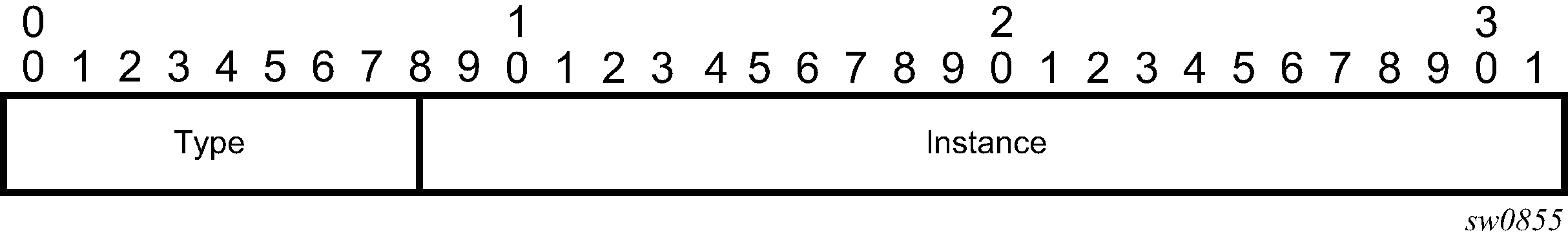
OSPF Opaque LSA packets are made up of the following, as shown in OSPF opaque LSA packet.
LSA ID is 202.255.238.0
opaque type value is 202
instance value is 255.238.0 (ffee00)
OSPF Opaque LSA type 10 TLV contains the following information:
vendor identifier
This is the vendor-id (vendor defined string).
type is 0x8000
length is length of identify string
default value is "Nokia"
equipment identifier
This is the product-id (vendor defined string).
type is 0x8001
length is length of identify string
default value is "chassis-name, chassis-type"
system-mac
This refers to node system MAC (node unique).
type is 0x8002
length is 6
default value is chassis MAC address
NEID
This refers to node hostname (customer defined).
type is 0x8003
length is 4
NEIP IPv4
This refers to loopback IPv4 address (preconfigured).
type is 0x8004
length is 4
NEIP IPv6
This refers to loopback IPv6 address (preconfigured).
type is 0x8005
length is 16
IPv4/IPv6
Both IPv4 and IPv6 node discovery is supported. However, LSA type 10 is only advertised on OSPFv2 and not OSPFv3. If the operator wants to use IPv6 or dual-stack, OSPFv2 must be configured under VPRN to advertise the node information using LSA type 10 opaque. In addition, OSPFV3 can also be enabled to advertise IPv6 routes and interfaces for IPv6 reachability. If both IPv4 and IPv6 are configured on the loopback interface within the VPRN (dual-stack) then both values are sent in the OSPFv2 LSA type 10, NMS prefers one over the other. In this case, all discovered routers must be configured with dual-stack OSPFv2 and OSPFv3.
Auto-provisioning using OSPF
SR OS supports the OSPF option for ZTP. The network element identifier (NEID) is configured using the chassis MAC address and the network element IP address (NEIP) is derived from the NEID. The first few slots and ports are auto-provisioned and the ZTP process tries to establish OSPF adjacency on these slots and ports to communicate the node information using type 10 opaque LSAs.
NEID
On a data communication network (DCN), a network element (NE) is uniquely identified by an ID (NEID), not by an IP address. Each NE is assigned a default NEID manually or through the auto-provisioning process.
The assigned NEIDs on a specific DCN must be different from each other because they represent the unique identities of the NEs on that DCN. If the NEIDs of two NEs on a DCN are identical, route flapping occurs.
The NEID range is from 0x10001 to 0xFEFFFE and consists of a subnet ID and basic ID. The first 8 most significant bits represent the subnet ID, which ranges from 0x1 to 0xFE. The 16 least significant bits represent the basic ID, which ranges from 0x0001 to 0xFFFE.
NEIP
NEIP addresses help managed terminals to access the NEs and allow addressing between NEs in IP networking. An NEIP address consists of a network number and a host number. A network number uniquely identifies a physical or logical link. All NEs along the same link have the same network number. A network number is obtained using the AND operation on the 32-bit IP address and corresponding subnet mask.
The NEIP address is derived from the NEID when the NE is initialized. The NEIP address is in the format 140.subnet number.basic ID. The vendor has assigned 140.x.y.z for Nokia routers.
For example, if the NEID is 0x09BFE0, which is 1001.10111111.11100000 in binary format, the NEIP address is derived as follows.
The subnet number is represented by the 8 most significant bits 00001001, which is 9 in decimal format. 9 is the default value.
The basic ID is represented by the 16 least significant bits 10111111.11100000, which is 191.224 in decimal format.
The NEIP address derived from the NEID 0x09BFE0 is 140.9.191.224.
Until the NEIP is configured manually, the NEIP address is derived from the NEID; changes to the NEID cause the associated NEIP address to change. After the NEIP address is configured manually, that NEIP no longer changes when the associated NEID changes.
NEIP and NEID autogenerate CLI configuration
The IPv4 format of NEIP is x.y.a.b. Where:
x is the vendor ID value
y is NEID subnet
a.b is the host portion of the NEID.
Use the following CLI commands to configure NEID and NEIP autogeneration
Use the following command to configure the NEID.
configure system network-element-discovery profile neidThe NEID can be set manually or the host portion can be set. If the host portion is set, the subnet is automatically set to 09.
- Use the following commands to configure the NEIP in IPv4 and IPv6 formats, respectively.
configure system network-element-discovery profile neip ipv4
configure system network-element-discovery profile neip ipv6
When the NEIP is derived from the NEID, the NEID value is used as the subnet number and the host portion of the NEIP. You can configure the vendor ID value. The default vendor ID value is 140.
Auto-provisioning using OSPF
The node is auto-provisioned using OSPF if the auto-boot ospf flag is set in the BOF. When this flag is set, the node automatically creates the necessary configuration for a management VPRN and automatically generates the NEIP as described in Autogenerate configuration. The NEID must be configured and staged as described in NEIP and NEID autogenerate CLI configuration.
Autogenerate configuration
When the auto-boot ospf flag is set in the BOF, the node is configured in the following sequence:
west and east port configuration and the associated MTU
a management VPRN
a network element profile configured under the following context.
configure system network-element-discoveryrouter ID in VPRN set to the NEIP address
loopback interface in VPRN with the same IP address configured as the network element profile NEIP
a physical interface in VPRN (SAP) with an unnumbered interface that inherits the IP from the loopback IP (this is light VPRN, where the uplink is a SAP and not a spoke SDP)
VLAN dot1q support for the above L3 interface with the VLAN set to 4094
a temporary username and password configured for the node, which can be the default
OSPF on the physical L3 interface in the VPRN (SAP). OSPF is configured as P2P and has an additional flag to include the type 10 opaque LSA value.
Telnet and FTP servers enabled under the system security context
SSH, Telnet, and FTP management are supported in the VPRN; they are disabled by default.
Node discovery is done through a VPRN and SAP interface. A GRT configuration is not required.
Autogenerate NEID configuration
When the auto-boot ospf flag is used without any options, the NEID is autogenerated from the chassis MAC address. The least significant bytes of the chassis MAC address can be 00 or FF. These values are invalid as least significant bytes of an IP address. SR OS uses the following methods to mitigate these invalid bytes:
For IPv4, the least significant chassis MAC bytes (3 to 5) are used to generate the NEID. The bytes are shift to the left by 2 bits and ‟logical OR”-ed with 01 to generate the least significant 3 bytes of the IPv4 address.
For IPv6, the least significant chassis MAC bytes (2 to 6) are used to generate the NEID. The bytes are shift to the left by 2 bits and ‟logical OR”-ed with 01 to generate the least significant 5 bytes of the IPv6 address.
The auto-boot ospf flag and options
If the auto-boot ospf flag is set in the BOF, the node enters auto-discovery mode and automatically creates the management VPRN and its required configuration.
The auto-boot ospf flag options can be set manually in the BOF or by editing the bof.cfg file. For information about these options, see the auto-boot ospf command description in the CLI help or the command reference guide:
- 7450 ESS, 7750 SR, 7950 XRS, and VSR MD-CLI Command Reference Guide
- 7450 ESS, 7750 SR, 7950 XRS, and VSR Classic CLI Command Reference Guide
CLI generation of the loopback address and router ID using auto-boot ospf options
The loopback address and the Router ID in the management VPRN are set to the NEIP address automatically. When auto-boot ospf is executed, the configuration is generated automatically.
After node connectivity has been established, these addresses can be changed by an administrator account. If these addresses are changed using the CLI, OSPF renegotiates its neighboring session and uses the new addresses.
The only way to regenerate these addresses automatically is to change the bof auto-boot ospf option and to reboot the node.
If no options are specified for auto-boot ospf, the management VPRN configuration is set as follows:
NEID host must be set by the user.
NEIP vendor-id-value is set to 140.
The node goes through the ports with links operationally up and tries to establish OSPF adjacencies. If the OSPF adjacency is established on an interface, the interface is kept and the LSA type 10 TLV is advertised. The node can bring up multiple OSPF adjacencies in the discovery mode.
Port MTU is set to the default value for the port type.
OSPF MTU is set to 1500.
If options are specified for auto-boot ospf, they are used when the management VPRN CLI is created automatically. The mapping of the auto-boot ospf options to CLI commands is displayed in Mapping of auto-boot ospf options to CLI commands
| Option | Commands |
|---|---|
|
neid |
configure system network-element-discovery profile neid hex-string |
|
neip-ipv4 |
configure system network-element-discovery profile neip ipv4 a.b.c.d |
|
neip-ipv6 |
configure system network-element-discovery profile neip ipv6 x:x:x:x:x:x:x:x |
|
no explicit neip-ipv4 or neip-ipv6 |
configure system network-element-discovery profile neip ipv4 auto-generate and configure system network-element-discovery profile neip ipv6 auto-generate |
|
vendor-id set and no explicit neip-ipv4 or neip-ipv6 value |
configure system network-element-discovery profile neip ipv4 auto-generate [vendor-id-value value] and configure system network-element-discovery profile neip ipv6 auto-generate [vendor-id-value value] |
|
ospf-mtu |
configure service vprn ospf area interface mtu |
|
port-mtu |
configure port ethernet mtu |
Auto-provisioning details
The node is shipped with the default bof.cfg file. The operator must stage the node and execute auto-boot ospf and the NEID accordingly.
At bootup, the application reads the ospf flag and performs the following functions:
The node discovers and provisions the chassis and the cards according to the connectivity requirement for the chassis.
The card and slot discovery and provisioning depend on whether the port option is set under auto-boot ospf. If the port option is set, the corresponding IOM or MDAs are discovered.
It does not load any configuration file.
If you set only the option neid for auto-boot ospf, the following occurs.
A vendor ID value of 140 is assigned automatically.
Vendor ID is the most significant byte in the NEIP. By default, it is set to 140.
Default ports and default MTUs are set up automatically.
The configuration is set up based on these default values.
If you set additional options for auto-boot ospf, the following occurs:
These values are used to generate the configuration as described in CLI generation of the loopback address and router ID using auto-boot ospf options.
Vendor ID is the most significant byte in the NEIP. By default, it is set to 140.
Either all or some of these options can be set. The options that are not set remain at their default values.
These configured options generate the configuration as described in CLI generation of the loopback address and router ID using auto-boot ospf options.
-
Always disable generate-traps because it applies only to non-aggregation nodes.
- MD-CLI
configure system network-element-discovery generate-traps false - classic
CLI
configure system network-element-discovery no generate-traps
- MD-CLI
This configuration process forces the node to generate its auto-discovery profile and to advertise it through OSPF to the rest of the network.
An aggregation node must be configured manually and cannot be auto-discovered. This is because the node is connected to the NMS and must have an SNMP configuration to connect to the NMS.
Use the following commands to configure the node to generate the NEIP automatically.
configure system network-element-discovery profile neip ipv4 auto-generate
configure system network-element-discovery profile neip ipv6 auto-generate
If either of the following are set, the IP address is 140.9.c.d.
auto-boot ospf vendor-id 140
configure system network-element-discovery profile vendor-id Nokia
When the NMS has discovered the nodes, the NMS or the user can SSH to the node and clear the auto-boot ospf flag manually. In addition, the following operational guidelines apply:
After node discovery, all management and operations are performed through Telnet, SSH, or SNMP.
The NE profile and management VPRN and its configuration that was autogenerated (as described in Autogenerate configuration) are not deleted, unless explicitly deleted by the user. These are valid configurations generated automatically during auto-provisioning. They should perform the following actions to manage these valid, autogenerated configuration.
Execute an admin save to save these configurations in the configuration file. If a previous configuration file exists, the existing configuration file is backed up and a new configuration file with the current configuration is saved on the compact flash (CF).
Run the already existing configuration file. The management VPRN configuration should not overlap with the existing configuration file that is being executed.
Connectivity requirements
Most access topologies are ring-based, for which two interfaces are required with OSPF adjacency in VPRN. Two ports based on the chassis and auto-boot ospf options must be created and used to establish OSPF neighbor adjacencies. These interfaces should be created with VLAN 4094 for the auto-discovery process.
Auto-provisioning success
The node declares auto-provisioning success when the OSPF adjacency is created and the node has advertised the type 10 opaque LSA TLV with the node information using OSPF. When a single OSPF adjacency is created, the auto-boot ospf process declares success and does not reboot the node; the node resumes normal operational mode. However, the process tries indefinitely to bring up OSPF on other ports with link up.
If the NMS has discovered the node, the operator can log in to the node and disable auto-boot ospf.
To terminate auto-boot ospf, the user must Telnet or SSH to the node and use the option in the user prompt or the tools command.
Auto-boot OSPF reboot timers
If auto-boot ospf is not successful (that is, no OSPF adjacency is found) for 30 minutes, the node is rebooted and auto-boot is retried.
Auto-boot OSPF relation with auto-boot
The auto-boot command without the ospf flag executes ZTP with DHCP discovery. The ospf flag forces the node discovery using OSPF.
Auto-provisioning log options
Detailed auto-provisioning logs are gathered in a dedicated log queue that can be displayed with the tools dump auto-boot log command. At the end of ZTP, these logs are also written to the autoboot.log file.
Console access during auto-provisioning
While the node is running auto-provisioning, the console is accessible and node configuration is possible and accepted. If the configuration is saved during the auto-provisioning, the save operation is honored. If ZTP is running in the background, a warning message is displayed on each login to notify the user that the system can reboot as a result of ZTP.
Disabling OSPF auto-provisioning
If the node is executing auto provisioning (auto-boot), a warning message is displayed when the user logs in. The warning message gives the user the option of terminating the auto-boot process. The auto-boot ospf flag is cleared only if the user logs into the discovered node and disables the flag using Telnet/SSH or SNMP.
Auto-boot OSPF provisioning is a one-step process. If the OSPF adjacency is successfully initiated to the neighbor and goes operationally up, OSPF advertises the NE profile to the neighbor.
The management VPRN is deleted only if the user explicitly deletes it using VPRN configuration commands.
CLI structure
The NE discover feature supports profiles for NE discovery information. You can configure multiple profiles and assign each profile to a different VPRN. Each VPRN can only have a single profile and therefore a single NEID and NEIP.
Use the commands in the following context to configure NE discovery profiles.
configure system network-element-discovery profileAssigning the NE-discovery profile to IGP
You can assign an NE profile to advertise under a VPRN OSPF area. When you assign the profile to advertise, OSPF advertises the NE information to its neighbors through type 10 opaque LSA.
Use the following command to assign an NE profile to advertise under a VPRN OSPF area.
configure service vprn ospf area advertise-ne-profileAggregation node configuration
An aggregation node, attached to NMS through a VPRN service, aggregates all nodes to be discovered using the same VPRN. The node is configured with:
a management VPRN
a loopback address in VPRN
a physical interface in the VPRN with an optional unnumbered interface inheriting the IP address from the loopback IP (this is a light VPRN where the uplink is a SAP and not a spoke SDP)
optional VLAN DOT1Q support for the L3 interface
OSPF on the physical L3 interface in the VPRN (SAP)
SNMP (SNMPv3) on an L3 interface in the VPRN (SAP) toward the NMS
a MIB table build based on the OSPF type 10 opaque LSA and stored in the OSPF opaque database
This node converts the OSPF LSA type 10 opaque information arriving from the discovered nodes into an SNMP MIB table and updates the NMS with the MIB. The NMS uses the MIB to discover the node and opens a SSH or Telnet session to configure the node accordingly.
The node to be discovered is provisioned with a management VRF as described in Node discovery procedure. All of the necessary node information needed for the node discovery is advertised by OSPF using LSA type 10 opaque. Nodes can be chained together, so the LSA type 10 needs to be forwarded all the way to the aggregation node.
NMS discovers the node using SNMP MIB traps or it can walk the MIB table.
NMS connects to the discovered node using SSH or Telnet to update the configuration by CLI. The operator must ensure that none of their commands disable the management VPRN and disconnect the discovered node from NMS.
MIB requirements on the aggregation node
A new vendor-proprietary MIB table for node discovery, tmnxVRtrNeInfoTable, is defined as part of TIMETRA-VRTR-MIB.mib. This MIB table is used by the NMS to gather all node information by walking the table, for example, after an NMS reboot.
This MIB table is built on any node that receives OSPF type 10 LSA.
The MIB table should be built with a key of VRF and NEID and a data portion of neid, vendor identify, platform type, system-mac, neip-v4, and neip-v6.
The MIB parameters are:
The company name is configurable using the CLI and is a string, but by default, "Nokia" is sent.
tmnxSysNEProfVendorId            OBJECT-TYPE
    SYNTAX      DisplayString
    MAX-ACCESS  read-create
    STATUS      current
    DESCRIPTION
       "The value of tmnxSysNEProfVendorId specifies the
vendor identifier."
    DEFVAL      { "Nokia" }
    ::= { tmnxSysNEProfEntry 11 }
The device type is configurable and is a string, but by default, the chassis-name and the chassis-type is sent.
tmnxSysNEProfPlatformType        OBJECT-TYPE
    SYNTAX      DisplayString
    MAX-ACCESS  read-create
    STATUS      current
    DESCRIPTION
       "The value of tmnxSysNEProfPlatformType specifies
the product identifier.
        An empty string indicates this object is not
configured, the chassis name and chassis type will be
used."
    DEFVAL      { ''H }
    ::= { tmnxSysNEProfEntry 10 }
The tcIPRanDcnIpv4 and tcIpRanDcnIpV6 objects are the NEIPs configured using the CLI.
tmnxSysNEProfNeipV4Type          OBJECT-TYPE
    SYNTAX      InetAddressType
    MAX-ACCESS  read-create
    STATUS      current
    DESCRIPTION
       "The value of tmnxSysNEProfNeipV4Type specifies
the IP address type of tmnxSysNEProfNeipV4.
     The value of tmnxSysNEProfNeipV4Type can be either
of 'ipv4(1)' or 'unknown (0)'.
       The value of 'unknown(0)' specifies no NEIP v4
address is configured."
    DEFVAL      { unknown }
    ::= { tmnxSysNEProfEntry 5 }

tmnxSysNEProfNeipV4              OBJECT-TYPE
    SYNTAX      InetAddress (SIZE (0|4))
    MAX-ACCESS  read-create
    STATUS      current
    DESCRIPTION
       "The value of tmnxSysNEProfNeipV4 indicates the
IPv4 address of the Network Element."
    DEFVAL      { ''H }
    ::= { tmnxSysNEProfEntry 6 }

tmnxSysNEProfNeipV6Type          OBJECT-TYPE
    SYNTAX      InetAddressType
    MAX-ACCESS  read-create
    STATUS      current
    DESCRIPTION
       "The value of tmnxSysNEProfNeipV6Type specifies
the IP address type of tmnxSysNEProfNeipV6.
     The value of tmnxSysNEProfNeipV6Type can be either
of 'ipv6(2)' or 'unknown (0)'.
       The value of 'unknown(0)' specifies no NEIP v6
address is configured."
    DEFVAL      { unknown }
    ::= { tmnxSysNEProfEntry 7 }

tmnxSysNEProfNeipV6              OBJECT-TYPE
    SYNTAX      InetAddress (SIZE (0|16))
    MAX-ACCESS  read-create
    STATUS      current
    DESCRIPTION
       "The value of tmnxSysNEProfNeipV6 indicates the
IPv6 address of the Network Element."
    DEFVAL      { ''H }
    ::= { tmnxSysNEProfEntry 8 }

tmnxSysNEProfSystemMac           OBJECT-TYPE
    SYNTAX      MacAddress
    MAX-ACCESS  read-create
    STATUS      current
    DESCRIPTION
       "The value of tmnxSysNEProfSystemMac specifies
the system MAC address of the node.
       A value of all zeros indicates this object is
not configured, the chassis MAC address will be used."
    DEFVAL      { '000000000000'H }
    ::= { tmnxSysNEProfEntry 9 }
The MIB walk is as follows:
tmnxVRtrNeInfoNeidHex.7.0.65.66.67 = STRING: 0:41:42:43
tmnxVRtrNeInfoNeipV4Type.7.0.65.66.67 = INTEGER: ipv4(1)
tmnxVRtrNeInfoNeipV4.7.0.65.66.67 = Hex-STRING: 80 09 0A 01
tmnxVRtrNeInfoNeipV4PrefixLen.7.0.65.66.67 = Gauge32: 32
tmnxVRtrNeInfoNeipV6Type.7.0.65.66.67 = INTEGER: ipv6(2)
tmnxVRtrNeInfoNeipV6.7.0.65.66.67 = Hex-STRING: 3F FE 00 00 00 00 00 00 00 00 00 00 80 09 0A 01
tmnxVRtrNeInfoNeipV6PrefixLen.7.0.65.66.67 = Gauge32: 128
tmnxVRtrNeInfoSystemMac.7.0.65.66.67 = STRING: e:0:0:0:0:1
tmnxVRtrNeInfoPlatformType.7.0.65.66.67 = STRING: Dut-B,7750 SR-12e_ndef
tmnxVRtrNeInfoVendorId.7.0.65.66.67 = STRING: NokiaNotDefault
SNMP traps and gets
The NMS should be able to walk the entire discovery table or get a specific row using the appropriate key. This is required when the NMS is rebooted or needs to update its entire database.
If you configure the following command, every time a node is updated, added, or removed from the OSPF opaque database (using LSA type 10 opaque update) the system sends a trap to notify the NMS of the change.
configure system network-element-discovery generate-trapsThe following traps are sent:
{tmnxVRtrNeInfoNeidHex.4.0.65.66.67 00:41:42:43}
{tmnxVRtrNeInfoNeipV4Type.4.0.65.66.67 ipv4}
{tmnxVRtrNeInfoNeipV4.4.0.65.66.67 0x80:09:0a:01}
{tmnxVRtrNeInfoNeipV4PrefixLen.4.0.65.66.67 32}
{tmnxVRtrNeInfoNeipV6Type.4.0.65.66.67 ipv6}
{tmnxVRtrNeInfoNeipV6.4.0.65.66.67 0x3f:fe:00:00:00:00:00:00:00:00:00:00:80:09:0a:01}
{tmnxVRtrNeInfoNeipV6PrefixLen.4.0.65.66.67 128}
{tmnxVRtrNeInfoSystemMac.4.0.65.66.67 0e:00:00:00:00:01}
{tmnxVRtrNeInfoPlatformType.4.0.65.66.67 {Dut-B,7750 SR-12e_ndef}}
{tmnxVRtrNeInfoVendorId.4.0.65.66.67 NokiaNotDefault}