Security
Authentication, authorization, and accounting
This chapter describes authentication, authorization, and accounting (AAA) used to monitor and control network access on routers. Network security is based on a multi-step process. The first step, authentication, validates a user’s credentials. The second step, authorization, allows the user to access and execute commands at various command levels based on profiles assigned to the user.
The third step, accounting, keeps track of the activity of users who have accessed the network. The type of accounting information recorded can include a history of the commands executed, the amount of time spent in the session, the services accessed, and the data transfer size during the session. The accounting data can be used for trend analysis, billing, and auditing purposes.
Configure routers to use local, Remote Authentication Dial In User Service (RADIUS), Lightweight Directory Access Protocol (LDAP), or Terminal Access Controller Access Control System Plus (TACACS+) security to validate users who attempt to access the router by console, Telnet, SSH, NETCONF, FTP, and more. Select the authentication order, which determines the authentication method to try first, second, third, or fourth.
The router supports the following security features:
-
local security can be implemented for authentication and authorization
-
LDAP can be implemented for authentication in the Base routing instance
-
RADIUS can be used for authentication, authorization, and accounting in the Base routing instance or a VPRN
-
TACACS+ can be used for authentication, authorization, and accounting in the Base routing instance or a VPRN
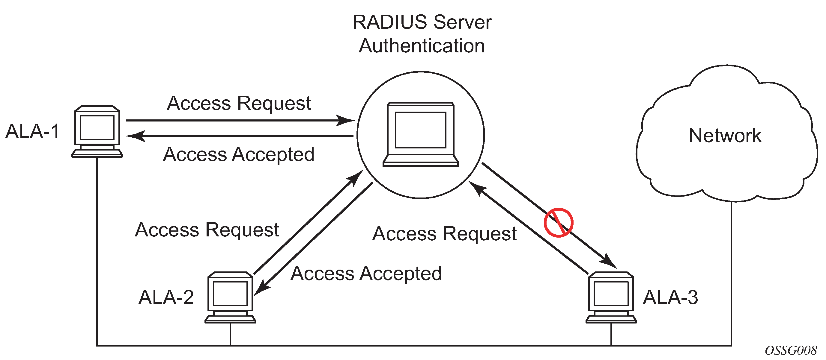
The following figure depicts end user access-requests sent to a RADIUS server. After validating the usernames and passwords, the RADIUS server returns an access-accept message to the users on ALA-1 and ALA-2. The username and password from ALA-3 could not be authenticated; therefore, access was denied.
Authentication
Authentication validates a user’s credentials when a user attempts to log in.
When a user attempts to log in through the console, FTP, or other methods, the client sends credentials to the router. Based on the received credentials, the router creates and sends an authentication request to a RADIUS, TACACS+, LDAP, or local database. The order in which the router tries different types of AAA servers and local databases is defined by the configured authentication order.
Transactions between the router and a RADIUS or TACACS+ server are authenticated through the use of a shared secret. The secret is never transmitted over the network. TLS can be used for the connection between the router and the LDAP or RADIUS server. User passwords are sent encrypted between the client and the AAA (RADIUS, TACACS+, or LDAP) server which prevents someone snooping on an insecure network to learn password information.
If the AAA server (of the chosen authentication method) does not respond within a specified time, the router issues the access request to the next configured servers of the same authentication method. Each AAA server must be configured identically to guarantee consistent results.
If any AAA server rejects the authentication request, it sends an access reject message to the router. In this case, no access request is issued to any other AAA servers of the chosen authentication method. However, if other authentication methods, such as TACACS+ and/or local, are configured and the option exit-on-reject is not set, then these methods are attempted. If no other authentication methods are configured, or all methods reject the authentication request, then access is denied.
For the AAA server selection, round-robin is used if multiple AAA servers for one particular authentication method are configured. Although, if the first alive server in the list cannot find a username, the router does not re-query the next server in the AAA server list for that authentication method and denies the access request. It may get authenticated on the next login attempt if the next selected AAA server has the appropriate username. It is recommended that the same user databases are maintained for AAA servers to avoid inconsistent behavior.
The user login is successful when the AAA server accepts the authentication request and responds to the router with an access accept message.
Implementing authentication without authorization for the routers does not require the configuration of VSAs (Vendor Specific Attributes) on the RADIUS server. However, users, user access permissions, and command authorization profiles must be configured on each router.
Any combination of these authentication methods can be configured to control network access from a router:
Local authentication
Local authentication uses PKI or usernames and passwords as authentication credentials to authenticate login attempts. The authentication credentials are local to each router, not to user profiles.
By default, local authentication is enabled. When one or more of the other security methods are enabled, local authentication is used in case it is configured as first method in the authentication order, or if other authentication methods are configured before local in the authentication order and fail.
Locally, usernames, public keys, and password management information can be configured. This is referred to as local authentication.
RADIUS authentication
Remote Authentication Dial-In User Service (RADIUS) is a client/server security protocol and software that enables remote access servers to communicate with a central server to authenticate dial-in users and authorize access to the requested system or service.
RADIUS allows administrators to maintain user profiles in a shared central database and provides better security, allowing a company to set up a policy that can be applied at a single administered network point.
RADIUS server selection
The RADIUS server selection algorithm is used by different applications:
RADIUS operator management
RADIUS authentication for Enhanced Subscriber Management
RADIUS accounting for Enhanced Subscriber Management
RADIUS PE-discovery
In all these applications, up to five RADIUS servers pools (per RADIUS policy, if used) can be configured.
The RADIUS server selection algorithm can work in 2 modes, either Direct mode or Round-robin mode.
Direct mode
The first server is used as the primary server. If this server is unreachable, the next server, based on the server index, of the server pool is used. This continues until either all servers in the pool have been tried or an answer is received.
If a server is unreachable, it will not be used again by the RADIUS application for the next 30 seconds to allow the server to recover from its unreachable state. After 30 seconds the unreachable server is available again for the RADIUS application. If in these 30 seconds the RADIUS application receives a valid response for a previously sent RADIUS packet on that unreachable server, the server will be available for the RADIUS application again, immediately after reception of that response.
Round-robin mode
The RADIUS application sends the next RADIUS packet to the next server in the server pool. The same server non-reachability behavior is valid as in the Direct mode.
Server reachability detection
A server is reachable, when the operational state UP, when a valid response is received within a timeout period which is configurable by the retry parameter on the RADIUS policy level.
A server is treated as not-reachable, if the operational state is down when the following occurs:
a timeout
If a number of consecutive timeouts are encountered for a specific server. This number is configurable by the retry parameter on RADIUS policy level.
a send failed
If a packet cannot be sent to the RADIUS server because the forwarding path toward the RADIUS server is broken (for example, the route is not available, the is interface shutdown, and so on), then, no retry mechanism is invoked and immediately, the next server in line is used.
A server that is down can only be used again by the RADIUS algorithm after 30 seconds, unless, during these 30 seconds a valid RADIUS reply is received for that server. Then, the server is immediately marked UP again.
The operational state of a server can also be ‟unknown” if the RADIUS application is not aware of the state of the RADIUS server (for example, if the server was previously down but no requests had been sent to the server, therefore, it is not specified yet whether the server is actually reachable).
Application-specific operator management
By default, the server access mode is Direct, but it can be changed into Round-Robin. A health-check function is available for operator management, which can optionally be disabled. The health-check polls the server every 30 seconds (configurable) with an improbable username. If the server does not respond to this health-check, it is marked down.
If the first server in the list cannot find a user, the next server in the RADIUS server list is queried, only when access mode is set to Round-Robin. If multiple RADIUS servers are used and access mode is set to Direct, it is assumed they all have the same user database.
Application-specific RADIUS authentication
If the first server in the list cannot find a user, the next server in the RADIUS server list is not queried and access is denied. If multiple RADIUS servers are used, it is assumed they all have the same user database.
Application-specific RADIUS challenge/response interactive authentication
Challenge-response interactive authentication is used for key authentication where the RADIUS server is asking for the valid response to a displayed challenge. The challenge packet includes a challenge to be displayed to the user, such as a unique generated numeric value unlikely ever to be repeated. Typically this is obtained from an external server that knows what type of authenticator is in the possession of the authorized user and can therefore choose a random or non-repeating pseudorandom number of appropriate length.
The user then enters the challenge into his device (or software) and it calculates a response, which the user enters into the client which forwards it to the RADIUS server within an access request. If the response matches the expected response, the RADIUS server allows the user access, otherwise it rejects the response.
Use the following command to enable RADIUS challenge/response mode:
- MD-CLI
configure system security aaa remote-servers radius interactive-authentication - classic
CLI
configure system security radius interactive-authentication
RADIUS interactive authentication is disabled by default. The option needs to be enabled using CLI. Enabling interactive authentication under CLI does not mean that the system uses RADIUS challenge/response mode by default. The configured password authentication-order option is used. If the authentication-order option is local RADIUS, the system will first attempt to login the user using local authentication. If this fails, the system will revert to RADIUS and challenge/response mode. The authentication-order will precede the RADIUS interactive-authentication mode.
Even if the authentication-order is RADIUS local, the standard password prompt is always displayed. The user enters a username and password at this prompt. If RADIUS interactive-authentication is enabled the password does not have to be the correct password because authentication is accomplished using the RADIUS challenge/response method. The user can enter any password. The username and password are sent to the RADIUS server, which responds with a challenge request that is transmitted back to the node by the RADIUS server. When the user enters the challenge response, the response is authenticated by the RADIUS server to allow node access to the user.
For example, if the system is configured with system security authentication-order set to local RADIUS, at the login prompt the user can enter the username ‟admin” and the corresponding password. If the password for local authentication does not match, the system falls into RADIUS authentication mode. The system checks the interactive-authentication configuration and if it is enabled it enters into challenge/response mode. It sends the username and password to the RADIUS server, and the server sends the challenge request back to the node and to the user where it appears as a challenge prompt on screen. A challenge received from the RADIUS server typically contains a string and a hardware token that can be used to generate a password on the users’ local personal token generator. For example, the RADIUS server may send the challenge prompt ‟Enter response for challenge 12345:” to the SR OS. The string ‟12345” can be entered in the local token generator which generates the appropriate challenge response for the entered string. This challenge response can then be entered on the SR OS prompt for authorization.
When the user enters the correct challenge response it is authenticated using the RADIUS server. The server authenticates the user and the user gains access to the node.
If session timeout and Idle timeout values are configured on the RADIUS server, these are used to govern the length of time before the SR OS cancels the challenge prompt. If the user is idle longer than the received idle-timeout (seconds) from the RADIUS server, and/or if the user does not press ENTER before the received session-timeout (seconds).
If the idle/session attribute is not available or if the value is set to a very large number, the SR OS uses the smallest value set in ‟configure system login-control idle-timeout” and the idle/session timeout attribute value to terminate the prompt. If the ‟login-control idle-timeout” is disabled, the maximum idle-timeout (24-hours) is used for the calculation.
The SR OS displays the log-in attempts/failure per user in the ‟show system security user username” screen. If the RADIUS rejects a challenge response, it counts as a failed login attempt and a new prompt is displayed. The number of failed attempts is limited by the value set for ‟configure system security password attempt.” An incorrect challenge response results in a failure count against the password attempts.
Application-specific RADIUS accounting
RADIUS accounting can be used for two purposes:
CLI command accounting
Enhanced Subscriber Management subscriber host accounting
The RADIUS accounting application tries to send all the accounting records of a subscriber host to the same RADIUS server. If that server is down, then the records are sent to the next server, and from that moment on, the RADIUS application uses that server as the destination for accounting records for that subscriber host. Enhanced Subscriber Management applies to the 7750 SR platform.
Application-specific RADIUS PE-discovery
If the first server in the list cannot find a user, the next server in the RADIUS server list is not queried and access is denied. If multiple RADIUS servers are used, it is assumed they all have the same user database.
The RADIUS PE-discovery application makes use of a 10 second time period instead of the generic 30 seconds and uses a fixed consecutive timeout value of 2 (see Server reachability detection).
As long as the Session-Timeout (attribute in the RADIUS user file) is specified, it is used for the polling interval. Otherwise, the configured polling interval is used (60 seconds by default).
TACACS+ authentication
Terminal Access Controller Access Control System (TACACS) is an authentication protocol that allows a remote access server to forward a user's login password to an authentication server to determine whether access can be allowed to a specific system. TACACS is an encryption protocol and therefore less secure than the later Terminal Access Controller Access Control System Plus (TACACS+) and RADIUS protocols.
TACACS+ and RADIUS have largely replaced earlier protocols in the newer or recently updated networks. TACACS+, which uses Transmission Control Protocol (TCP), is popular because TCP is thought to be a more reliable protocol. RADIUS combines authentication and authorization. TACACS+ separates these operations.
LDAP authentication
Lightweight Directory Access Protocol (LDAP) can provide authentication, authorization, accounting (AAA) functionality, and can allow users to access the full virtualized data center and networking devices. SR OS currently supports LDAP provision of a centralized authentication method with public key management. The authentication method is based on SSH public keys or keyboard authentication (username, password).
Administrators can access networking devices with one private key; public keys are usually saved locally on the SSH server. Proper key management is not feasible with locally-saved public keys on network devices or on virtual machines, as this would result in hundreds of public keys distributed on all devices. LDAPv3 provides a centralized key management system that allows for secure creation and distribution of public keys in the network. Public keys can be remotely saved on the LDAP server, which makes key management much easier, as shown in Key management.
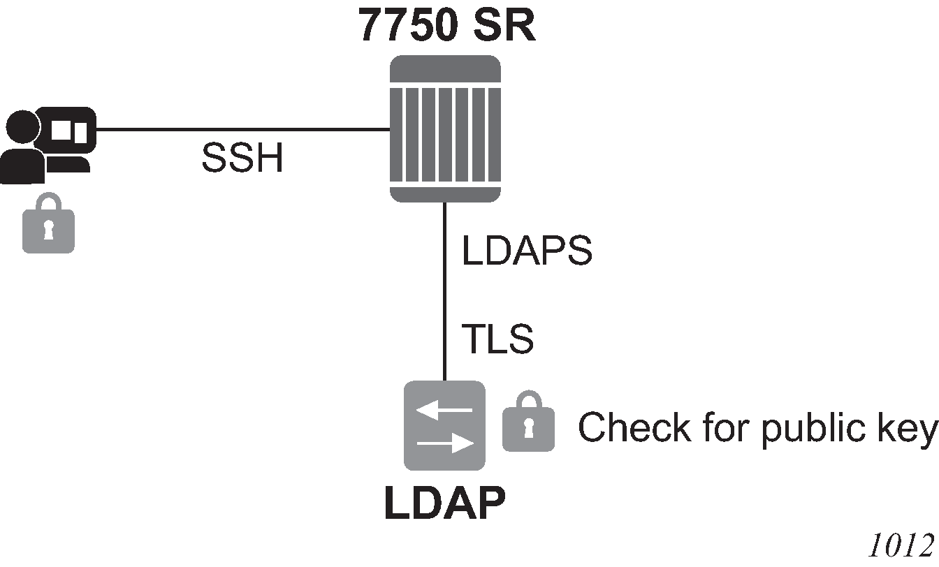
The administrator starts an SSH session through an SSH client using their private key. The SSH client for the authentication method sends a signature created with the user’s private key to the router. The router authenticates the signature using the user’s public key and gives access to the user. To access the public key, the router looks up the public key stored on the LDAP server and the public key stored locally. The order in which the public keys are looked up is defined by the authentication order. Communication between the router and the LDAP server should be secured with LDAP over SSL/TLS (LDAPS). After opening successfully a secured connection, LDAP returns a set of public keys that can be used by the router to verify the signature.
LDAP is integrated into the SR OS as an AAA protocol alongside existing AAA protocols, such as RADIUS and TACACS+. The AAA framework provides tools and mechanisms (such as method lists, server groups, and generic attribute lists) that enable an abstract and uniform interface to AAA clients, irrespective of the actual protocol used for communication with the AAA server.
The authentication functions are:
public key authentication
The client tries to SSH to the SR OS using public keys.
Public keys can be stored locally or on the LDAP server and retrieved as needed to authenticate the user.
password authentication (keyboard interactive)
The LDAP server can be used for user authentication using keyboard interactive, as with simple username and password authentication.
LDAP authentication process
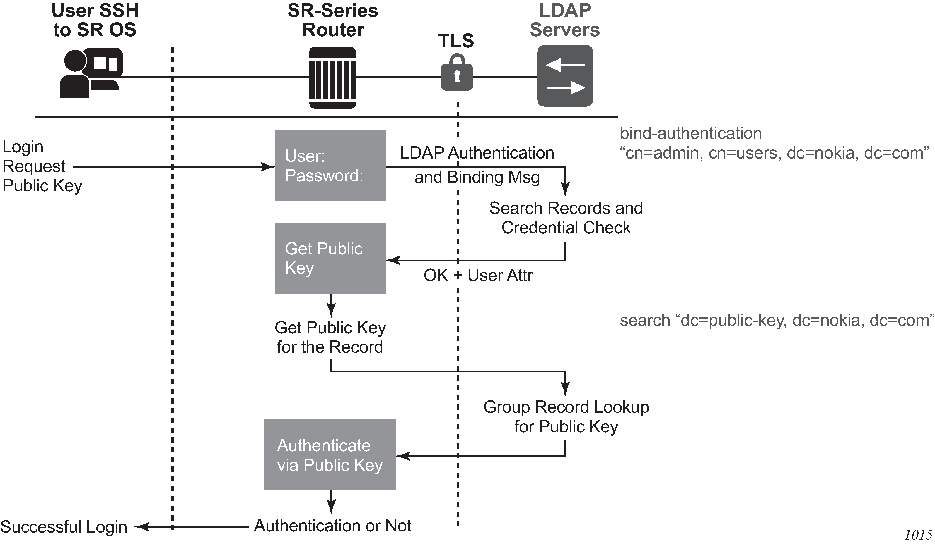
A client starts an LDAP session by connecting to an LDAP server, called a Directory System Agent (DSA), which–by default–are on TCP port 389 and UDP port 636 for LDAP. The SR OS then sends an operation request to the server, and the server sends responses in return, as shown in LDAP server and SR OS interaction for retrieving the public key. With some exceptions, the client does not need to wait for a response before sending the next request, and the server may send the responses in any order. All information is transmitted using Basic Encoding Rules (BER).
In the SR OS, the client can request the following operations:
StartTLS
Uses the LDAPv3 Transport Layer Security (TLS) extension for a secure connection.
Bind
Authenticates and specifies the LDAP protocol version.
Search
Searches for and retrieves directory entries.
Unbind
Closes the connection (not the inverse of Bind).
The connection between the router as the LDAP client and the LDAP server should be encrypted using TLS, as all credentials between the router and LDAP are transmitted in clear text.
Authentication order
SR OSsupports local and LDAP public key storage, the order of which is configurable. Use the following command to configure authentication order:
- MD-CLI
configure system security user-params authentication-order - classic
CLI
configure system security password authentication-order
The SR OS sends available authentication methods to the client and supports public key and password authentication. Use the following command to configure the client to use the public key authentication method:
- MD-CLI
configure system security aaa remote-servers ldap public-key-authentication - classic CLI
configure system security ldap public-key-authentication
If the client chooses the public key and LDAP is first in authentication order, the SR OS tries to authenticate using public key retrieval from the LDAP server. If the public key retrieval from LDAP server fails and exit-on-reject is not configured, the SR OS tries the next method (local) in the authentication order for the public key. If the next method also fails, a user authentication fail message is sent to the client.
If the public key retrieval from the LDAP server fails and exit-on-reject is configured, the SR OS does not try the next method in the authentication order. A user-authentication fail message is sent to the client. At this point, the client can be configured to only use public key authentication or use both public key authentication followed by password authentication. If the client is configured to use password authentication, it goes through the authentication order again (for example, it tries all the configured methods in the configured authentication order) as long as exit-on-reject is not configured.
Authentication order public key detail
There are two keys for public key authentication: a private key stored on the client and a public key stored on the server (local) or AAA server (LDAP). The client uses the private key to create a signature, which only the public key can authenticate. If the signature is authenticated using the public key, then the user is also authenticated and is granted access. SR OS can locally store, using CLI, as many as 32 RSA keys and 32 ECDHA keys for a single user. In total, the SR OS can load a maximum of 128 public keys in a single authentication attempt.
If the client has another private key, it can create a new signature with this new private key and attempt the authentication one more time, or switch to password authentication.
The following steps describe the procedure where the client attempts to authenticate using a public key and the authentication order is configured as ldap, then local.
The SSH client opens a session and tries to authenticate the user with private-key-1 (creating signature-1 from private-key-1).
The SR OS checks the authentication order.
The SR OS loads public keys for the user, as follows.
If exit-on-reject is not configured, the SR OS loads all public keys from the LDAP server and all public keys from the locally-saved location.
If exit-on-reject is configured, the SR OS only loads all public keys from the LDAP server and not from the locally-saved location.
The SR OS compares received client signature-1 with signature calculated from loaded public keys and attempts to find a match.
If a match is found, the user is authenticated. The procedure ends.
If no match is found, authentication fails and the SSH client is informed. The LDAP server waits for the SSH client’s reaction.
The SSH client reacts in one of several ways.
The connection is closed.
The password authentication method is continued. In this case, on the SR OS, the number of failed authentication attempts is not incremented.
The next public key is continued, as follows.
If it is not 21st received public key, return to step 3.
If it is the 21st received public key, the number of failed authentication attempts is incremented and the connection is closed.
LDAP authentication using a password
In addition to public key authentication, the SR OS supports password (keyboard) authentication using the LDAP server.
In the following example, the client attempts to authenticate using a password and only LDAP is configured in the authentication order.
The client uses Telnet or SSH to reach the SR OS.
The SR OS retrieves the username and password (in plain text).
-
The SR OS performs a bind operation to the LDAP server. Use the following command to set the root DN and password:
- MD-CLI
configure system security aaa remote-servers ldap server bind-authentication password configure system security aaa remote-servers ldap server bind-authentication root-dn - classic
CLI
configure system security ldap server bind-authentication password password root-dn
- MD-CLI
The SR OS performs a search operation for the username on LDAP server.
If the username is found, LDAP sends user_distinguished_name to the router.
If the username is not found, the authentication fails. The attempt and failed attempt counters are incremented.
The SR OS performs a bind operation to LDAP with user_distinguished_name and the password from step 2.
The LDAP server checks the password.
If the password is correct, the bind operation succeeds. The failed attempt and successful attempt counters are incremented.
If the password is incorrect, bind is unsuccessful and authentication fails. The attempt and failed attempt counters are incremented.
The SR OS sends a message to unbind from the LDAP server.
Timeout and retry configuration for the LDAP server
Use the following commands to configure the number of retry attempts and the response timeout for the LDAP server:
- MD-CLI
configure system security aaa remote-servers ldap server-retry configure system security aaa remote-servers ldap server-timeout - classic
CLI
configure system security ldap retry
configure system security ldap timeout
The server retry value is the maximum number of connection attempts that the SR OS can make to reach the current LDAP server before attempting the next server. For example, if the value is set to the default of 3, the SR OS tries to establish the connection to current server three times before attempting to establish a connection to the next server.
The server timeout value is the number of seconds that the SR OS waits for a response from the server with which it is attempting to establish a connection. If the server does not reply within the specified timeout value, the SR OS increments the retry counter by one. The SR OS attempts to establish the connection to the current server up to the configured retry value before moving to the next configured server.
TLS behavior and LDAP
RFC 4511 section 4.14.1 states, ‟A client requests TLS establishment by transmitting a StartTLS request message to the server” and ‟The client MUST NOT send any LDAP PDUs at this LDAP message layer following this request until it receives a StartTLS Extended response”. As such, if an LDAP has a TLS profile configured and the TLS is in an operationally down state, no LDAP packets are transmitted if TLS negotiation has not been completed, including when the TLS profile is shut down.
LDAP health check
The LDAP health-check function is available for operator management purposes and can be disabled. The SR OS health check attempts to establish a TCP connection to the LDAP server and polls the server at a specified interval (the default is 30 seconds). The TCP connection is closed by an LDAP unbind message.
Use the following command to configure the health check for LDAP:
- MD-CLI
configure system security aaa health-check - classic
CLI
configure system security password health-check
LDAP redundancy and TLS
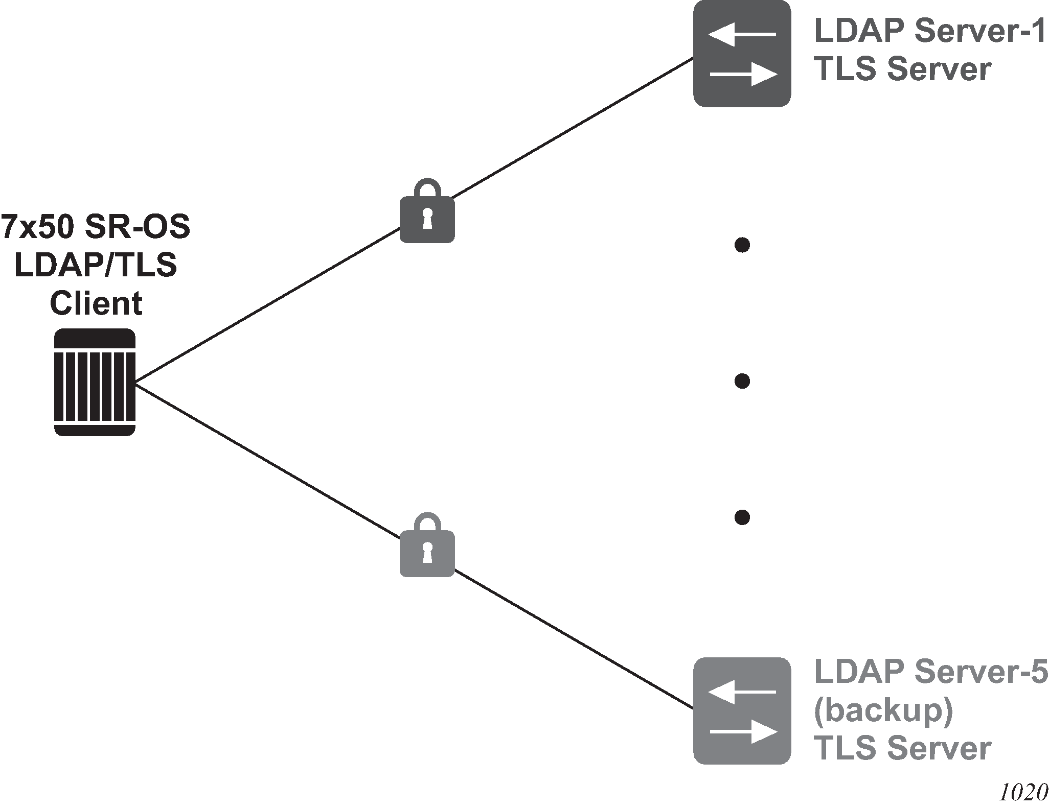
LDAP supports up to five redundant (backup) servers. Depending on the configuration of timeout and retry values, if an LDAP server is found to be out of service or operationally down, the SR OS will switch to the redundant servers. The SR OS will try the next LDAP server in the server list by choosing the next largest configured server index.
LDAP servers can use the same TLS profile or can have their own TLS profile. Each TLS profile can have a different configuration of trust-anchor, cipher-list and cert-profile. For security reasons, the LDAP server could be in different geographical areas and, therefore, each will be assigned its own server certificate and trust anchor. The TLS profile design allows users to mix and match all components.
Redundant LDAP servers are shown in LDAP and TLS redundancy.
Password hashing
SR OS supports multiple algorithms for user password hashing, including bcrypt and PBKDF2. The PBKDF2 algorithm can use SHA2 (SHA-256) or SHA3 (SHA-512) for hashing.
Use the following command to configure the algorithm to hash all user passwords:
- MD-CLI
configure system security user-params local-user password hashing - classic CLI
configure system security password hashing
When password hashing is configured, the following sequence of steps occurs at login:
The node checks the stored password and notes its hash algorithm.
The password entered by the user is hashed with the noted algorithm, and the node compares the hash with the stored user password hash.
If the entered and the stored passwords are the same, and if the hash algorithm of the stored user password is different than the hash algorithm of the system password, the user is prompted to enter a new password 2 times to ensure password match. The node stores this new password in the RAM (not in the system configuration file).
To store the new password in the configuration file, an admin user must perform an admin save command. If the admin save command is not executed, then on the next reboot the hash algorithm of the stored user password may be different than the system hash and the user must go through this process again from step 2.
After an upgrade to a software load that supports PBKDF2, the default password continues to be stored using the bcrypt algorithm. The following example describes the procedure to change the algorithm. In the example, the algorithm is changed to PBKDF2 and ‟User_name” can be any user.
User_name logs in and runs the hashing command to change the algorithm.
To save the algorithm change, an admin user performs an admin save command.
To store User_name’s password using PBKDF2, the admin user changes User_name’s password.
From this point onward, any new user passwords or changes to existing user passwords are stored using PBKDF2.
Authorization
The SR OS supports local, RADIUS, and TACACS+ authorization to control the actions of specific users. Any combination of these authorization methods can be configured to control actions of specific users:
Local authorization and RADIUS authorization operate by applying a command authorization profile that is associated in configuration with the user. The profiles are configured locally on the router or downloaded using VSAs from a RADIUS server. See Vendor-specific attributes.
Authorization applies to CLI access as well as NETCONF or gRPC access. See Authorization profiles for different interfaces for more details.
Local authorization
Local authorization uses user profiles and user access information after a user is authenticated. The profiles and user access information specifies the actions the user can and cannot perform.
By default, local authorization is enabled. Local authorization is disabled only when a different remote authorization method is configured, such as TACACS+ or RADIUS authorization and local is removed from the authorization order.
RADIUS authorization
RADIUS authorization grants or denies access permissions for a router. Permissions include the use of FTP, Telnet, SSH (SCP), and console access. When granting Telnet, SSH (SCP) and console access to the router, authorization can be used to limit what CLI commands the user is allowed to issue and which file systems the user is allowed or denied access.
When a user has been authenticated using RADIUS (or another method), the router can be configured to perform authorization. The RADIUS server can be used to:
download the user profile to the router
send the profile name that the node should apply to the router
Profiles consist of a suite of commands that the user is allowed or not allowed to execute. When a user issues a command, the authorization server looks at the command and the user information and compares it with the commands in the profile. If the user is authorized to issue the command, the command is executed. If the user is not authorized to issue the command, then the command is not executed.
Profiles must be created on each router and should be identical for consistent results. If the profile is not present, then access is denied.
Supported authorization configurations displays the following scenarios:
Remote (RADIUS) authorization cannot be performed if authentication is done locally (on the router).
The reverse scenario is supported if RADIUS authentication is successful and no authorization is configured for the user on the RADIUS server, then local (router) authorization is attempted, if configured in the authorization order.
When authorization is configured and profiles are downloaded to the router from the RADIUS server, the profiles are considered temporary configurations and are not saved when the user session terminates.
| Router | RADIUS supplied profile | |
|---|---|---|
Router configured user |
✓ | |
RADIUS server configured user |
✓ | ✓ |
TACACS+ server configured user |
✓ |
When using authorization, maintaining a user database on the router is not required. Usernames can be configured on the RADIUS server. Usernames are temporary and are not saved in the configuration when the user session terminates. Temporary user login names and their associated passwords are not saved as part of the configuration.
TACACS+ authorization
TACACS+ command authorization operates in one of three ways:
all users who authenticate via TACACS+ can use a single common default command authorization profile that is configured on the SR OS
each command attempted by a user is sent to the TACACS+ server for authorization
operator can configure local profiles and map tacplus priv-lvl based authorization to those profiles (the use-priv-lvl option)
To use a single common default command authorization profile to control command authorization for TACACS+ users, you can enable the tacplus default user template and configure the tacplus default option for the user template to point to a valid local profile. You must also disable tacplus authorization. Use the following commands to configure a single common default command profile for user authorization:
- MD-CLI
configure system security aaa remote-servers tacplus use-default-template configure system security aaa user-template user-template-name tacplus-default configure system security aaa remote-servers tacplus authorization - classic
CLI
configure system security tacplus use-default-template
configure system security user-template tacplus_default
configure system security tacplus authorization
If the default template is not being used for TACACS+ authorization and the tacplus authorization command is enabled without the use-priv-lvl option, each CLI command issued by an operator is sent to the TACACS+ server for authorization. The authorization request sent by the SR OS contains the first word of the CLI command as the value for the TACACS+ cmd and all following words become a cmd-arg. Quoted values are expanded so that the quotation marks are stripped off and the enclosed value are seen as one cmd or cmd-arg.
When the authorization use-priv-lvl command is used, the router maps the priv-lvl returned by the TACACS+ server to a local profile as configured under the priv-lvl-map command. Command authorization then uses the local profile. If the TACACS+ server does not return a priv-lvl, and the tacplus use-default-template command is enabled, the router uses the local profile configured in the tacplus default for command authorization.
TACACS+ authorization examples
The following examples show CLI commands and resulting AV pairs used for TACACS+ authorization.
Commands typed in the CLI
A:node-2#show
A:node-2#show router
A:node-2#show port 1/1/1
A:node-2#configure port 1/1/1 description ‟my port”
AV pairs resulting from commands typed in the CLI
The commands typed in the previous example result in the following AV pairs.
cmd=show

cmd=show
cmd-arg=router

cmd=show
cmd-arg=port
cmd-arg=1/1/1

cmd=configure
cmd-arg=port
cmd-arg=1/1/1
cmd-arg=description
cmd-arg=my port
For TACACS+ authorization, the SR OS sends the entire CLI context in the cmd and cmd-arg and values. The following example shows different contexts in the classic CLI. In the MD-CLI, the same concept applies.
CLI contexts usd for TACACS+ authorization
A:node-2# configure service
A:node-2>config>service# vprn 555 customer 1 create
A:node-2>config>service>vprn$ shutdown
AV pairs resulting from command contexts typed in the CLI
The contexts shown in the previous example result in the following AV pairs.
cmd=configure
cmd-arg=service

cmd=configure
cmd-arg=service
cmd-arg=vprn
cmd-arg="555"
cmd-arg=customer
cmd-arg=1
cmd-arg=create

cmd=configure
cmd-arg=service
cmd-arg=vprn
cmd-arg="555"
cmd-arg=customer
cmd-arg=1
cmd-arg=create
cmd-arg=shutdown
Configuration command authorization in model-driven interfaces
Configuration command authorization sends multiple requests that may be the same depending on the configuration changes. In model-driven interfaces, command authorization is required for the following changes to the candidate configuration:
the command that was entered; for example, system name node-2
the resulting configuration changes, because other elements may be modified or deleted; for example, delete router "Base" deletes the entire Base router configuration, and all of the deletions must be authorized
If the command authorization fails, the resulting configuration changes are not authorized.
Multiple authorization requests are also sent in the following cases:
-
for MD-CLI compound commands where multiple elements are changed in one command, as shown in the following examples.
system name node-2 location NYC system name node-2 } router router-id 10.1.1.1 -
configuration changed by an element's YANG modeling constraints, such as "choice" or "when" statements
The following example shows how setting the system name is an operation that changes one configuration element.
[ex:/configure]
A:admin@node-2# system name foo
# Command authorization
cmd=configure
cmd-arg=system
cmd-arg=name
# Resulting change authorization
cmd=configure
cmd-arg=system
cmd-arg=name
The following log example shows that the memory context and the console command are mutually exclusive, and configuring a new value deletes the existing value. The system must also authorize the deletion.
Existing configuration
[ex:/configure log log-id "42" destination]
A:admin@node-2# info
    memory {
    }
Configuration commands
[ex:/configure log log-id "42" destination]
A:admin@node-2# console
Resulting configuration
*[ex:/configure log log-id "42" destination]
A:admin@node-2# info
    console
Command authorization requests
# Command authorization
cmd=configure
cmd-arg=log
cmd-arg=log-id
cmd-arg=42
cmd-arg=destination
cmd-arg=console
# Resulting change authorization for console
cmd=configure
cmd-arg=log
cmd-arg=log-id
cmd-arg=42
cmd-arg=destination
cmd-arg=console
# Resulting change authorization for memory
cmd=configure
cmd-arg=log
cmd-arg=log-id
cmd-arg=42
cmd-arg=destination
cmd-arg=memory
Deleting access operation authorization in model-driven interfaces
Use either of the following commands in model-driven interfaces, to configure the system to use TACACS+ authorization requests to send the delete operation in the cmd argument and the path in the cmd-arg argument. These commands configure TACACS+ to allow modification and deletion. All deletions use the same TACACS+ cmd=delete request format.
configure system security aaa remote-servers tacplus authorization request-format delete
configure service vprn aaa remote-servers tacplus authorization request-format deletedelete configure system name
configure delete system name
configure system delete nameThe following example shows the AV pairs that are sent.
[ex:/configure system]
A:admin@node2# delete name

# Command authorization
cmd=delete
cmd-arg=configure
cmd-arg=system
cmd-arg=name
# Resulting change authorization
cmd=delete
cmd-arg=configure
cmd-arg=system
cmd-arg=name
Authorization profiles for different interfaces
Authorization profiles can be configured in any format. Depending on the configuration, a match may be hit. Each entry in a profile can be formatted for the classic CLI or the MD-CLI. Nokia recommends creating separate profiles for each interface type.
Authorization checks are not performed by default for telemetry data. All configuration and state elements are available to authenticated telemetry subscriptions, with the exception of LI (Lawful Intercept) configuration and state elements, which are authorized separately based on the LI authorization configuration. Use the following command to control telemetry data authorization:
- MD-CLI
configure system security aaa management-interface output-authorization telemetry-data - classic
CLI
configure system security managment-interface output-authorization telemetry-data
Authorization and match hit based on entry format shows authorization and match hit based on the entry format configuration. This is true whether authorization is done using local user profiles or using an AAA server like TACACS+ or RADIUS.
| Profile entry format | Classic CLI | MD-CLI | NETCONF | gNMI set and get (gRPC) |
|---|---|---|---|---|
Classic CLI |
Yes |
Maybe |
Maybe |
Maybe |
MD-CLI |
Maybe |
Yes |
Yes |
Yes |
Authorization support
Authorization support lists the authorization support using a local profile or an AAA server.
|
Classic CLI | MD-CLI | NETCONF | gNMI set and get (gRPC) |
|---|---|---|---|---|
LDAP |
— |
— |
— |
— |
TACACS+ |
Yes |
Yes |
Yes |
Yes |
RADIUS |
Yes |
Yes |
Yes |
Yes |
Local |
Yes |
Yes |
Yes |
Yes |
System-provisioned AAA command authorization profiles
SR OS provides the following built-in (system-provisioned) AAA command authorization profiles, these profiles can be removed or modified:
default
administrative
The built-in profiles are applicable to users using the classic CLI or the MD-CLI, and contain rules that apply to classic CLI and rules that apply to MD-CLI interfaces in the same profile.
By default, in SR OS, the administrative profile is associated with the built-in user called 'admin'.
In the classic CLI, the default profile is automatically assigned to any newly-created user, but the operator can remove the profile from any user and replace it with another profile. The classic CLI also has an internal mechanism that denies access to show system security commands for all users, so users must be given access to these commands with a permit entry in a profile.
In the MD-CLI, a newly-created user is not associated with any profile. The operator can manually associate a user with the default profile if required.
Configuring authorization support for configuration groups
To configure authorization for configuration groups explicitly, create an entry for the group configuration in the user’s profile.
For example, to deny access to router interfaces in both the main configuration branch and in the group configuration branch, create an entry for each one.
In the following example, entry 10 prevents the user from viewing, creating, and editing router interfaces in the main configuration branch and from inheriting router interface configurations from configuration groups. Entry 20 prevents the user from viewing, creating, and editing router interfaces in the group configuration branch.
[ex:/configure system security aaa local-profiles profile "exampleProfile"]
A:admin@node-2# info
    entry 10 {
        match "configure router interface"
        action deny
    }
    entry 20 {
        match "configure groups group router interface"
        action deny
    }
Accounting
RADIUS accounting
Accounting can be configured independently from RADIUS authorization and RADIUS authentication.
When enabled, RADIUS accounting sends command line accounting from the router to the RADIUS server on UDP port 1813 or TCP port 2083 with TLS. The server receives accounting requests and returns a response to the router indicating that it has successfully received the request. Each command issued on the router generates a record sent to the RADIUS server. The record identifies the user who issued the command and the timestamp. If no response is received in the time defined in the timeout parameter, the accounting request must be retransmitted until the configured retry count is exhausted. A trap is issued to alert the NMS (or trap receiver) that the server is unresponsive. The router issues the accounting request to the next configured RADIUS server (up to 5).
User passwords and authentication keys of any type are never transmitted as part of the accounting request.
TACACS+ accounting
The SR OS allows the administrator to configure the type of accounting record packet that is to be sent to the TACACS+ server when specified events occur on the device. The accounting record-type parameter indicates whether TACACS+ accounting start and stop packets be sent or just stop packets be sent. Start/stop messages are only sent for individual commands, not for the session.
When a user logs in to request access to the network using Telnet or SSH, or a user enters a command for which accounting parameters are configured, or a system event occurs, such as a reboot or a configuration file reload, the router checks the configuration to see if TACACS+ accounting is required for the particular event.
If TACACS+ accounting is required, then, depending on the accounting record type specified, sends a start packet to the TACACS+ accounting server which contains information about the event.
The TACACS+ accounting server acknowledges the start packet and records information about the event. When the event ends, the device sends a stop packet. The stop packet is acknowledged by the TACACS+ accounting server.
Command accounting log events
In addition to RADIUS and TACACS+ accounting, SR OS supports a set of log events dedicated to command accounting.
For the following log events related to command accounting, see the SR OS Log Events Guide:
cli_user_io
snmp_user_set
cli_config_io
cli_unauth_user_io
cli_unauth_config_io
md_cli_io
md_cli_unauth_io
netconf_auth
netconf_unauth
grpc_auth
grpc_unauth
Security controls
Configure routers to use RADIUS, TACACS+, LDAP, and local authentication to validate users requesting access to the network. The order in which authentication is processed among RADIUS, TACACS+, LDAP, and local can be specifically configured. In other words, the authentication order can be configured to process authorization through TACACS+ first, then RADIUS for authentication and accounting. Local access can be specified next in the authentication order if the RADIUS and TACACS+ servers are not operational. The security methods capabilities are listed in Security methods capabilities.
| Method | Authentication | Authorization | Accounting1 |
|---|---|---|---|
Local |
✓ | ✓ | Not supported |
TACACS+ |
✓ | ✓ | ✓ |
RADIUS |
✓ | ✓ | ✓ |
LDAP |
✓ | Not supported |
Not supported |
When a server does not respond
A trap is issued if a RADIUS server is unresponsive. An alarm is raised if RADIUS is enabled with at least one RADIUS server and no response is received to either accounting or user access requests from any server.
Periodic checks to determine if the primary server is responsive again are not performed. If a server is down, it is not contacted for 5 minutes. If a login is attempted after 5 minutes, then the server is contacted again. When a server does not respond with the health check feature enabled, the server’s status is checked every 30 seconds. Health check is enabled by default. When a service response is restored from at least one server, the alarm condition is cleared. Alarms are raised and cleared on Nokia’s Fault Manager or other third-party fault management servers.
The servers are accessed in order from lowest to highest specified index (from 1 to 5) for authentication requests until a response from a server is received. A higher indexed server is only queried if no response is received, implying a lower indexed server is not available. If a response from the server is received, no other server is queried.
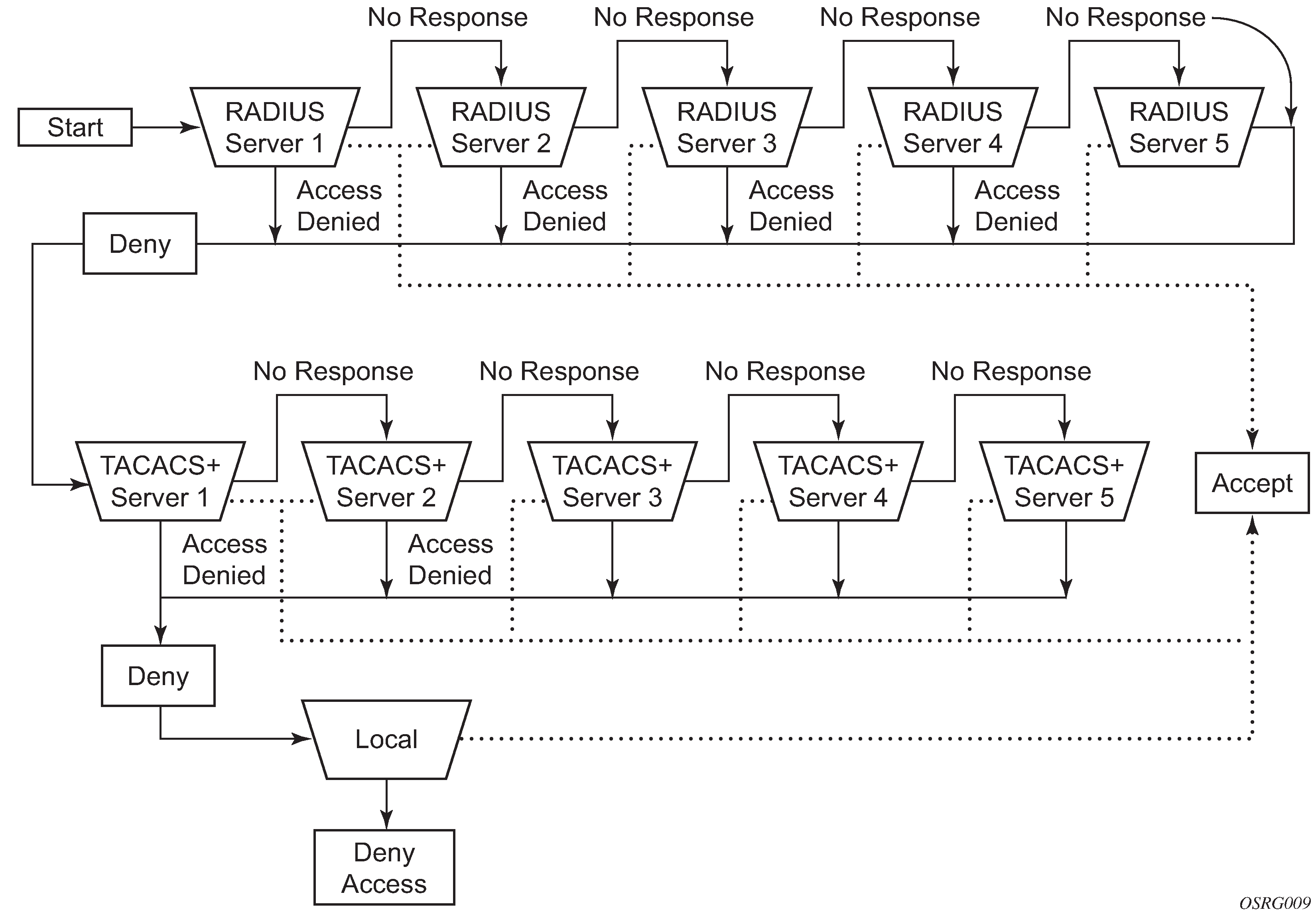
Access request flow
Use the commands in the following context to define the authentication process shown in Security flow:
- MD-CLI
configure system security user-params local-user password - classic
CLI
configure system security password
The authentication order is determined by specifying the sequence in which authentication is attempted among RADIUS, TACACS+, LDAP, and local. This example uses the authentication order of RADIUS, then TACACS+, and finally, local. An access request is sent to RADIUS server 1. One of two scenarios can occur. If there is no response from the server, the request is passed to the next RADIUS server with the next lowest index (RADIUS server 2) and so on, until the last RADIUS server is attempted (RADIUS server 5). If server 5 does not respond, the request is passed to the TACACS+ server 1. If there is no response from that server, the request is passed to the next TACACS+ server with the next lowest index (TACACS+ server 2) and so on.
If a request is sent to an active RADIUS server and the username and password is not recognized, access is denied and passed on to the next authentication option, in this case, the TACACS+ server. The process continues until the request is either accepted, denied, or each server is queried. Finally, if the request is denied by the active TACACS+ server, the local parameters are checked for username and password verification. This is the last chance for the access request to be accepted.
Control and management traffic protection
SR OS routers support an extensive set of configurable mechanisms to protect the CPU from being flooded with control or management traffic.
These protection mechanisms are a set of configurable hardware-based filters, classification, queuing, and rate-limiting functions that drop unwanted traffic before it reaches the control processor.
- In-band traffic extracted from the line cards to the CPM:
-
Line card features:
-
ACLs filters: IPv4, IPv6, and MAC
-
anti-spoofing, uRPF
-
distributed CPU protection
-
-
CPM features:
-
CPM Filters: IPv4, IPv6, and MAC
-
centralized CPU Protection
-
per-peer queues, protocol queues, CPM queues
-
-
Out-band and in-band traffic: Management access filters
CPM filters
CPM filters are hardware-based filters used to restrict traffic from the line cards directed to the CPM CPU, such as control and management packets. This filtering is performed by the CPM complex and consumes no resources on the CPM CPU.
Packets from all network and access ports extracted to the CPM CPU are filtered by the CPM filter policy. Packets originating from a management Ethernet port can be filtered using management access filters, see Management Access Filter for more information.
- CPM filter is performed by a line card complex using 7750 SR-a, 7750 SR-e, 7750 SR-1, 7750 SR-1s, and 7750 SR-2s.
- CPM filter is not supported on the VSR.
CPM filter packet match
Use the commands in the following context to configure the three different CPM filter policies: ip-filter, ipv6-filter, and mac-filter.
configure system security cpm-filterThe CPM filter packet match rules are listed below.
Each CPM filter policy is an ordered list of entries. Entries must be sequenced correctly from the most explicit to the least explicit.
If multiple match criteria are specified in a single CPM filter policy entry, all criteria must be met for the packet to be considered a match against that policy entry (logical AND).
Any match criteria not explicitly defined is ignored during a match.
A CPM filter policy entry defined without any match criteria is inactive.
A CPM filter policy entry with match criteria defined, but no action configured, inherits the default action defined at the cpm-filter level.
The cpm-filter default-action applies to IPv4, IPv6, or MAC CPM filters that are in an administratively enabled state.
When mac-filter, ip-filter, and ipv6-filter are applied to a specific packet, the mac-filter is applied first.
CPM IPv4 and IPv6 filter entry match criteria
The supported IPv4 and IPv6 match criteria types are shown in the following tables.
Basic Layer 3 match criteria lists the basic Layer 3 match criteria.
| Criteria | Description |
|---|---|
DSCP |
Matches the specified DSCP value against the DSCP/Traffic Class field in the IPv4 or IPv6 packet header. |
SRC IP, DST IP |
Matches the specified source/destination IPv4/IPv6 address prefix/mask against the source/destination IPv4/IPv6 address field in the IP packet header. Optionally, operators can match a list of IP addresses defined in filter match-list ip-prefix-list or match-list ipv6-prefix-list. The prefix-list can be defined statically or using the apply-path command to automatically populate using configured BGP peers defined in the base router or VPRN services. For more details on filter match-list configuration and capabilities, see the 7450 ESS, 7750 SR, 7950 XRS, and VSR Router Configuration Guide, "Match list for filter policies". |
fragment |
For IPv4, match against the MF bit or Fragment Offset field to determine if the packet is a fragment. For IPv6 match against the next-header field or Fragment Extension Header value to determine whether the packet is a fragment. Up to six extension headers are matched against to find the Fragmentation Extension Header. |
IPv4 options match criteria lists the IPv4 options match criteria.
| Criteria | Description |
|---|---|
IP option |
Matches the specified option value in the first option of the IPv4 packet. Optionally, operators can configure a mask to be used in a match. |
option-present |
Matches the presence of IP options in the IPv4 packet. Padding and EOOL are also considered as IP options. Up to six IP options are matched against. |
multiple-option |
Matches the presence of multiple IP options in the IPv4 packet. |
IPv6 next-header match criteria lists the IPv6 next-header match criteria.
| Criteria | Description |
|---|---|
hop-by-hop |
Matches for the presence of hop-by-hop options extension header in the IPv6 packet. This match criterion is supported on ingress only. Up to six extension headers are matched against. |
Upper-layer protocol match criteria lists the upper-layer protocol match criteria.
| Criteria | Description |
|---|---|
next-header |
Matches the specified upper-layer protocol (such as TCP or UDP) against the next-header field of the IPv6 packet header. ‟*” can be used to specify TCP or UDP upper-layer protocol match (logical OR). Next-header matching also allows matching on the presence of a subset of IPv6 extension headers. See the CLI section for information about which extension header match is supported. |
protocol |
Matches the specified protocol against the Protocol field in the IPv4 packet header (for example, TCP, UDP, or IGMP) of the outer IPv4. ‟*” can be used to specify TCP or UDP upper-layer protocol match (logical OR). |
ICMP code |
Matches the specified value against the Code field of the ICMP/ICMPv6 header of the packet. This match is supported only for entries that also define protocol/next-header match for ICMP/ICMPv6 protocol. |
ICMP type |
Matches the specified value against the Type field of the ICMP or ICMPv6 header of the packet. This match is supported only for entries that also define protocol/next-header match for ‟ICMP” or ‟ICMPv6” protocol. |
SRC port, DST port, port |
Matches the specified port value (with or without mask), port list, or port range against the Source Port Number/Destination Port Number of the UDP/TCP packet header. An option to match either source or destination port or both (logical OR) using a single filter policy entry is supported by using a directionless port command. Source/destination match is supported only for entries that also define protocol/next-header match for ‟TCP”, ‟UDP”, or ‟TCP or UDP” protocols. A non-initial fragment does not match an entry with non-zero port criteria specified. |
TCP flags ack and syn |
Matches the presence or absence of the TCP flags in the TCP header of the packet. This match criteria also requires defining the protocol/next-header match as ‟TCP”. |
Router instance match criteria lists the router instance match criteria.
| Criteria | Description |
|---|---|
router |
Matches the router instance packets that are ingressing from for this filter entry. |
CPM MAC filter entry match criteria
The MAC match criteria are evaluated against the Ethernet header of the Ethernet frame.
Router instance match criteria lists the router instance match criteria.
| Criteria | Description |
|---|---|
frame-type |
The filter matches a specific type of frame format. For example, configuring frame-type ethernet_II matches only Ethernet-II frames. |
SRC mac |
Matches the specified source MAC address frames. Optionally, operators can configure a mask to be used in a match. |
DST mac |
Matches the specified destination MAC address frames. Optionally, operators can configure a mask to be used in a match. |
etype |
Matches the specified Ethernet II frames. The Ethernet type field is a two-byte field used to identify the protocol carried by the Ethernet frame. |
ssap |
Matches the specified frames with a source access point on the network node designated in the source field of the packet. Optionally, operators can configure a mask to be used in a match. |
dsap |
Matches the specified frames with a destination access point on the network node designated in the destination field of the packet. Optionally, operators can configure a mask to be used in a match. |
CFM opcode |
Matches the specified packet with the specified cfm-opcode. |
CPM filter policy action
The two main CPM filter actions allow the option to accept or drop traffic.
Optionally, traffic can be sent to a user-configured hardware queue using a CPM filter. Nokia recommends this primarily for temporary debug or attack investigation activities.
CPM filter policy statistics and logging
For more information, see the 7450 ESS, 7750 SR, 7950 XRS, and VSR Router Configuration Guide, "Filter policy" and "Filter policy logging".
CPM filter: protocols and ports
Nokia recommends using a strict CPM filter policy allowing traffic from trusted IP subnets for protocols and ports actively used in the router and to explicitly drop other traffic.
Protocols and ports identifies which ports are used by which applications in the SR OS. The source port and destination port reflect the CPM filter entry configuration for traffic ingressing the router and sent to the CPM.
| Src port number | Dst port number | IP protocol | Application | Description | Accessible out of band | Accessible in band |
|---|---|---|---|---|---|---|
|
20 |
TCP |
FTP |
FTP server data. Active FTP client. |
Yes |
Yes |
|
|
21 |
TCP |
FTP |
FTP server control |
Yes |
Yes |
|
|
20 |
TCP |
FTP |
FTP client data |
Yes |
Yes |
|
|
21 |
TCP |
FTP |
FTP client control |
Yes |
Yes |
|
|
22 |
TCP |
SSH, NETCONF |
SSH server, NETCONF server |
Yes |
Yes |
|
|
22 |
TCP |
SSH |
SSH client. Responses for initiated TCP sessions. |
Yes |
Yes |
|
|
23 |
TCP |
Telnet |
Telnet server |
Yes |
Yes |
|
| 23 | — | TCP | Telnet | Telnet client. Responses for initiated TCP sessions. | Yes | Yes |
|
49 |
TCP |
TACACS+ |
TACACS+ client. Responses for initiated sessions. |
Yes |
Yes |
|
|
53 |
UDP |
DNS |
DNS client |
Yes2 |
Yes |
|
|
67 |
67 |
UDP |
DHCPv4 |
DHCPv4: Relay agent to server, server to relay agent, and relay agent to relay agent |
— |
Yes |
|
68 |
67 |
UDP |
DHCPv4 |
DHCPv4: client to relay agent/server |
— |
Yes |
|
67 |
68 |
UDP |
DHCPv4 |
DHCPv4: relay agent/server to client |
— |
Yes |
|
123 |
UDP |
NTP |
NTP server |
Yes |
Yes |
|
|
123 |
UDP |
NTP |
NTP client |
Yes |
Yes |
|
|
161 |
UDP |
SNMP |
SNMP server: SET and GET commands |
Yes |
Yes |
|
|
179 |
TCP |
BGP |
BGP: server terminated TCP sessions |
— |
Yes |
|
|
179 |
BGP |
BGP: client responses for initiated TCP session |
— |
Yes |
||
|
319 |
UDP |
PTP |
1588 PTP event |
— |
Yes |
|
|
320 |
UDP |
PTP |
1588 PTP general |
— |
Yes |
|
|
389 |
TCP |
LDAP |
LDAP client (non TLS) |
Yes |
Yes |
|
|
520 |
UDP |
RIP |
RIP |
— |
Yes |
|
|
546 |
547 |
UDP |
DHCPv6 |
DHCPv6 – client to server/relay agent |
— |
Yes |
|
547 |
547 |
UDP |
DHCPv6 |
DHCPv6 – server to relay agent, relay agent to server, and relay agent to relay agent |
— |
Yes |
|
639 |
UDP |
PIM |
MSDP: multicast source discovery protocol |
— |
Yes |
|
|
636 |
TCP |
LDAPS |
LDAP client over TLS |
— |
Yes |
|
|
646 |
UDP |
LDP |
LDP Hello adjacency |
— |
Yes |
|
|
646 |
TCP |
LDP |
LDP/T-LDP: terminated TCP sessions |
— |
Yes |
|
|
646 |
TCP |
LDP |
LDP/T-LDP: responses for initiated TCP sessions |
— |
Yes |
|
|
701 |
UDP |
LMP |
Link management protocol |
— |
Yes |
|
|
830 |
TCP |
NETCONF |
NETCONF server |
Yes |
Yes |
|
|
ANY |
UDP |
TWAMP |
TWAMP test |
— |
Yes |
|
|
862 |
TCP |
TWAMP |
TWAMP control: terminated TCP session |
— |
Yes |
|
|
862, 64364-64373 |
UDP |
TWAMP |
TWAMP Light (Reflector) |
— |
Yes |
|
|
862, 64364-64373 |
UDP |
TWAMP |
Nokia TWAMP Light Initiator. Non Nokia initiator may use the entire range. |
— |
Yes |
|
|
1025 |
UDP |
MC-LAG-APS-EP-IPsec |
Multi Chassis: LAG, APS (Automation Protection Switching), End Point, IPsec (MIMP), AARP |
— |
Yes |
|
|
1491 |
TCP |
SNMP Streaming |
SNMP streaming server |
Yes |
Yes |
|
|
1645 |
UDP |
RADIUS Proxy |
RADIUS proxy authentication |
— |
Yes |
|
|
1646 |
UDP |
RADIUS Proxy |
RADIUS proxy accounting |
— |
Yes |
|
|
1647 |
UDP |
RADIUS CoA |
RADIUS Dynamic Authorization (CoA/DM) |
Yes |
Yes |
|
|
1700 |
UDP |
RADIUS CoA |
RADIUS Dynamic Authorization (CoA/DM) |
Yes |
Yes |
|
|
1701 |
UDP |
L2TP |
L2TP server |
— |
Yes |
|
|
1812 |
UDP |
RADIUS CoA |
RADIUS Dynamic Authorization (CoA/DM) |
Yes |
Yes |
|
|
1812 |
UDP |
RADIUS |
RADIUS authentication |
Yes |
Yes |
|
|
1813 |
UDP |
RADIUS |
RADIUS accounting |
Yes |
Yes |
|
|
2000 |
UDP |
WPP |
Web portal authentication protocol |
— |
Yes |
|
|
2083 |
TCP |
RADIUS |
RADIUS over TLS |
Yes |
Yes |
|
|
2123 |
UDP |
GTP |
GTP control plane |
— |
Yes |
|
|
2123 |
UDP |
GTP |
GTP control plane |
— |
Yes |
|
|
2152 |
UDP |
GTP |
GTP user plane |
— |
Yes |
|
|
2152 |
UDP |
GTP |
GTP user plane |
— |
Yes |
|
|
3232 |
UDP |
PIM |
PIM MDT |
— |
Yes |
|
|
3503 |
UDP |
OAM |
LSP Ping, LSP Trace, VPRN Trace, VPRN Ping |
— |
Yes |
|
|
3868 |
UDP |
DIAMETER |
Diameter |
Yes |
Yes |
|
|
3784 |
UDP |
BFD |
BFD Control 1 hop BFD and BFD over MPLS LSP |
— |
Yes |
|
|
3785 |
UDP |
BFD |
BFD echo Seamless BFD echo mode for controlled return path |
— |
Yes |
|
|
3799 |
UDP |
RADIUS |
RADIUS Dynamic Authorization (CoA/DM) |
Yes |
Yes |
|
|
4189 |
TCP |
PCEP |
Path Computation Element Protocol |
Yes |
Yes |
|
|
4739 |
UDP |
NAT |
NAT debug |
— |
Yes |
|
|
4784 |
UDP |
BFD |
BFD control multi-hop |
— |
Yes |
|
|
4789 |
UDP |
VXLAN Ping |
VXLAN ping request |
— |
Yes |
|
|
4790 |
UDP |
VXLAN Ping |
VXLAN ping response |
— |
Yes |
|
|
5000 |
UDP |
Mtrace2 |
IP Multicast Mtrace2 |
— |
Yes |
|
|
5351 |
UDP |
NAT |
PCP NAT port mapping protocol |
— |
Yes |
|
|
6068 |
TCP |
ANCP |
ANCP – terminated TCP session |
— |
Yes |
|
|
6514 |
TCP |
Syslog |
Syslog over TLS |
Yes |
Yes |
|
|
6635 |
UDP |
MPLS over UDP |
MPLS over UDP OAM |
— |
Yes |
|
|
6653 |
TCP |
OpenFlow |
OpenFlow – terminated TCP sessions |
— |
Yes |
|
|
6784 |
UDP |
BFD |
uBFD |
— |
Yes |
|
|
8805 |
UDP |
PFCP |
Packet and forwarding control protocol – Used to install dynamic forwarding state |
— |
Yes |
|
|
33408-33535 |
UDP |
OAM |
OAM Traceroute |
— |
Yes |
|
|
45067 |
TCP |
MCS |
Multi-chassis synchronization – Terminated TCP Session (mcs, mc-ring, mc-ipsec) |
— |
Yes |
|
|
7784 |
UDP |
BFD |
Seamless BFD routed return path |
— |
Yes |
|
|
45067 |
TCP |
MCS |
Multi-chassis synchronization – Responses for initiated TCP session (mcs, mc-ring, mc-ipsec) |
— |
Yes |
|
|
49151 |
UDP |
L2TP |
L2TP |
— |
Yes |
|
|
57400 |
TCP |
gRPC |
gRPC |
Yes |
Yes |
|
|
64353 |
UDP |
MPLS DM |
MPLS Delay Measurement using UDP return object |
— |
Yes |
|
|
N/A |
N/A |
GRE |
GRE |
GRE |
— |
Yes |
|
N/A |
N/A |
ICMP |
ICMP |
ICMP |
Yes |
Yes |
|
N/A |
N/A |
IGMP |
IGMP |
IGMP |
— |
Yes |
|
N/A |
N/A |
OSPF |
OSPF |
OSPF |
— |
Yes |
|
N/A |
N/A |
PIM |
PIM |
PIM |
— |
Yes |
|
N/A |
N/A |
RSVP |
RSVP |
RSVP |
— |
Yes |
|
N/A |
N/A |
VRRP |
VRRP, SRRP |
VRRP, SRRP |
— |
Yes |
|
pki-server-port or 80/8080 |
any |
TCP |
PKI |
CMPv2 (Certificate Management Protocol v2) client – Responses for initiated TCP session |
— |
Yes |
|
pki-server-port |
any |
TCP |
PKI |
OCSP (Online Certificate Status Protocol) client – Responses for initiated TCP session |
— |
Yes |
|
pki-server-port or 80/8080 |
any |
TCP |
PKI |
Auto CRL (Certificate Revocation List) update (client) – Responses for initiated TCP session |
Yes |
Yes |
CPM per-peer queuing
Per-peer queuing provides isolation between peers by allocating hardware queues on a per-peer basis for the following TCP-based protocols: BGP, T-LDP, LDP, MSDP, Telnet, and SSH.
This mechanism guarantees fair and non-blocking access to shared CPU resources across all peers. For example, this ensures that an LDP-based DoS attack from a specific peer is mitigated and compartmentalized and not all CPU resources are dedicated to the overwhelming control traffic sent by that specific peer.
Use the following command to ensure that service levels are not (or are only partially) impacted in case of an attack toward BGP, T-LDP, LDP, MSDP, Telnet, or SSH.
configure system security per-peer-queuingUse the following commands to enable SSH and Telnet support for per-peer queuing.
configure system login-control ssh ttl-security
configure system login-control telnet ttl-security
CPM queues
CPM queues provides the operator with a tool that is primarily useful for debugging or investigations during an attack. When using the CPM queues, the following recommendations should be considered.
CPM queues can be used for temporary debug or attack investigation activities, in this case packets can be filtered and directed into the queue using the CPM filter.
CPM queues are not recommended for normal operation where the system default handling and isolation of protocols into protocol queues is already carefully balanced. If additional protection is needed, then the use of the Centralized CPU protection and Distributed CPU protection features is recommended.
Centralized CPU protection
SR OS CPU protection is a centralized rate-limiting function that operates on the CPM to limit traffic destined for the CPU. The term ‟centralized CPU protection” is referred to as ‟CPU protection” in this guide and in the CLI to differentiate it from ‟Distributed CPU Protection”.
CPU protection provides interface isolation by rate limiting the total amount of traffic extracted to the CPM per port, interface, or SAP in hardware using a combination of limits configurable at the CPU protection system level or as CPU protection policies assigned to access or network interfaces.
The following limits are configurable at the CPU protection system level:
link-specific rate
This applies to the link-specific protocols LACP (Ethernet LAG control) and Ethernet LMI (ELMI). The rate is a per-link limit (each link in the system has LACP/LMI packets limited to this rate).
port overall rate
This applies to all control traffic, the rate is a per-port limit, and each port in the system has control traffic destined for the CPM limited to this rate.
protocol protection
This blocks network control traffic for unconfigured protocols.
The following limits are configurable independently for access or network interfaces using a dedicated CPU protection policy:
overall rate
This applies to all control traffic destined for the CPM (all sources) received on an interface where the policy is applied. This is a per-interface limit. Control traffic received above this rate is discarded.
per-source rate
This is used to limit the control traffic destined for the CPM from each individual source. This per-source rate is only applied when an object (SAP) is configured with a CPU protection policy and also with the optional mac-monitoring or ip-src-monitoring commands. A source is defined as a SAP, Source MAC Address tuple for MAC monitoring and as a SAP, Source IP Address tuple for IP source monitoring. Only specific protocols (as configured under included-protocols in the CPU protection policy) are limited (per source) when ip-src-monitoring is used.
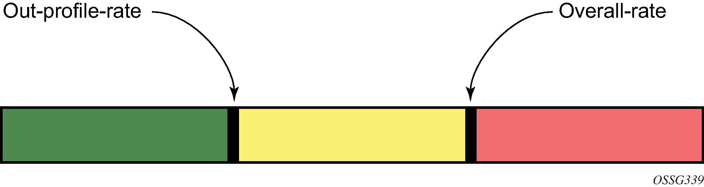
out-profile rate
This applies to all control traffic destined for the CPM (all sources) received on an interface where the policy is applied. This is a per-interface limit. Control traffic received above this rate is marked as discard eligible (such as, out-profile/low-priority/yellow) and is more likely to be discarded if there is contention for CPU resources.
There are two default CPU protection policies for access and network interfaces.
Policy 254:
This is the default policy that is automatically applied to access interfaces
Traffic above 6000 pps is discarded
overall-rate = 6000
per-source-rate = max
out-profile-rate = 6000
Policy 255:
This is the default policy that is automatically applied to network interfaces
Traffic above 3000 pps is marked as discard eligible, but is not discarded unless there is congestion in the queuing toward the CPU
overall-rate = max
per-source-rate = max
out-profile-rate = 3000
A three-color marking mechanism uses a green, yellow, and red marking function. This allows greater flexibility in how traffic limits are implemented. The out-profile-rate command within the CPU protection policy maps to the boundary between the green (accept) and yellow (mark as discard eligible/low priority) regions. The overall-rate command marks the boundary between the yellow and red (drop) regions point for the associated policy (Profile marking).
If the overall rate is set to 1000 pps and as long as the total traffic that is destined for the CPM and intended to be processed by the CPU is less than or equal to 1000 pps, all traffic is processed. If the rate exceeds 1000 pps, protocol traffic is discarded (or marked as discard eligible/low priority in the case of the out-profile-rate command) and traffic on the interface is affected.
This rate limit protects all the other interfaces and ensures that a violation from one interface does not affect the rest of the system.
CPU protection is not supported on 7750 SR-1, 7750 SR-1s, 7750 SR-2s, 7750 SR-e, 7750 SR-a, and 7750 VSR.
Protocol protection
Protocol protection allows traffic to be discarded for protocols not configured on the router. This helps mitigate DoS attacks by filtering invalid control traffic before it reaches the CPU. This is a feature of CPU Protection and can be enabled or disabled for the entire system.
When using the protocol-protection command, the system automatically maintains a per-interface list of configured protocols. For example, if an interface does not have IS-IS configured, then protocol protection discards any IS-IS packets received on that interface. Other protocols, such as L2TP, are controlled by the protocol protection at the VPRN service level.
Protocols controlled by the protocol-protection mechanism include:
GTP
IGMP
IS-IS
MLD
L2TP control
OSPFv2
OSPFv3
PPPoE
PIM
RIP
PFCP
The following protocols are protected independently from protocol protection:
The per-peer-queuing command protects BGP, LDP, T-LDP, MSDP, Telnet, and SSH.
BFD control packets are dropped if BFD is not configured on a specific interface.
CPU protection extensions for ETH-CFM
CPU protection supports the ability to explicitly limit the amount of ETH-CFM traffic that arrives at the CPU for processing. ETH-CFM packets that are redirected to the CPU by either a Management Endpoint (MEP) or a Management Intermediate Point (MIP) will be subject to the configured limit of the associated policy. Up to four CPU protection policies may include up to ten individual ETH-CFM-specific entries. The ETH-CFM entries allow the operator to apply a packet-per-second rate limit to the matching combination of level and opcode for ETH-CFM packet that are redirected to the CPU. Any ETH-CFM traffic that is redirected to the CPU by a Management Point (MP) that does not match any entries of the applied policy is still subject to the overall rate limit of the policy itself. Any ETH-CFM packets that are not redirected to the CPU are not subject to this function and are treated as transit data, subject to the applicable QoS policy.
The operator first creates a CPU policy and includes the required ETH-CFM entries. Overlap is allowed for the entries within a policy, first match logic is applied. This means ordering the entries in the correct sequence is important to ensure the correct behavior is achieved. Even though the number of ETH-CFM entries is limited to ten, the entry numbers have a valid range from 1 to 100 to allow for ample space to insert policies between one and other.
Ranges are allowed when configuring the level and the OpCode. Ranges provide the operator a simplified method for configuring multiple combinations. When more than one level or OpCode is configured in this manner the configured rate limit is applied separately to each combination of level and OpCode match criteria. For example, if the levels are configured as listed in Ranges versus levels and OpCodes, with a range of five (5) to seven (7) and the OpCode is configured for 3,5 with a rate of 1. That restricts all possible combinations on that single entry to a rate of 1 packet-per-second. In this example, six different match conditions are created.
| Level | OpCode | Rate |
|---|---|---|
5 |
3 |
1 |
5 |
5 |
1 |
6 |
3 |
1 |
6 |
5 |
1 |
7 |
3 |
1 |
7 |
5 |
1 |
When the policy is created, it must be applied to a SAP or binding within a service for these rates to take effect. This means the rate is on a per-SAP or per-binding basis. Only one policy may be applied to each SAP or binding. The eth-cfm-monitoring command must be configured in order for the ETH-CFM entries to be applied when the policy is applied to the SAP or binding. If this command is not configured, ETH-CFM entries in the policy are ignored. It is also possible to apply a policy to a SAP or binding by configuring the eth-cfm-monitoring command which does not have an MP. In this case, although these entries are enforced, no packets are redirected to the CPU.
By default, rates are applied on a per-peer basis. This means each individual peer is subject to the rate. Use the aggregate command to apply the rate to all peers. MIPs, for example, only respond to loopback messages and linktrace messages. These are typically on-demand functions and per-peer rate limiting is not required, making the aggregate function more appealing.
The eth-cfm-monitoring and mac-monitoring commands are mutually exclusive and cannot be configured on the same SAP or binding. The mac-monitoring command is used in combination with the traditional CPU protection and is not specific to ETH-CFM rate limiting feature described here.
When an MP is configured on a SAP or binding within a service which allows an external source to communicate with that MP, for example a User to Network Interface (UNI), eth-cfm-monitoring command with the aggregate command should be configured on all SAPs or bindings to provide the highest level of rate control.
The following example shows a policy configuration and the application of that policy to a SAP in a VPLS service configured with an MP. Policy 1 entry 10 limits all ETH-CFM traffic redirected to the CPU for all possible combinations to 1 packet-per-second. Policy 1 entry 20 limits all possible combinations to a rate of zero, dropping all request which match any combination. If entry 20 did not exist then only rate limiting of the entry 10 matches would occur and any other ETH-CFM packets redirected to the CPU would not be bound by a CPU protection rate.
MD-CLI
[ex:/configure system security cpu-protection policy 1 eth-cfm]
A:admin@node-2# info
    entry 10 {
        pir 1
        level start 5 end 7 { }
        opcode start 3 end 3 { }
        opcode start 5 end 5 { }
    }
    entry 20 {
        pir 0
        level start 0 end 7 { }
        opcode start 0 end 255 { }
    }

[ex:/configure service vpls "10"]
A:admin@node-2# info
    sap 1/1/4:100 {
        admin-state enable
        cpu-protection {
            policy-id 1
            eth-cfm-monitoring {
                aggregate
            }
        }
        eth-cfm {
            mip primary-vlan none {
            }
        }
    }
classic CLI
A:node-2>config>sys>security>cpu-protection#
  policy 1
    eth-cfm
      entry 10 level 5-7 opcode 3,5 rate 1
      entry 20 level 0-7 opcode 0-255 rate 0

A:node-2>config>service>vpls#
  sap 1/1/4:100
    cpu-protection 1 eth-cfm-monitoring aggregate
    eth-cfm
      mip
    no shutdown
ETH-CFM ingress squelching
CPU protection provides a granular method to control which ETH-CFM packets are processed. As indicated in CPU protection extensions for ETH-CFM, a unique rate can be applied to ETH-CFM packets classifying on specific MD-level and a specific OpCode and applied to both ingress (down MEP and ingress MIP) and egress (up MEP and egress MIP) extraction. This function is to protect the CPU on extraction when a Management Point (MP) is configured.
It is also important to protect the ETH-CFM architecture deployed in the service provider network. This protection scheme varies from CPU protection. This model is used to prevent ETH-CFM frames at the service provider MD-levels from gaining access to the network even when extraction is not in place. ETH-CFM squelching drops all ETH-CFM packets at or below the configured MD-level. The ETH-CFM squelch feature is supported at ingress only.
ETH-CFM hierarchical model shows a typical ETH-CFM hierarchical model with a subscriber ME (6), test ME (5), EVC ME (4) and an operator ME (2). This model provides the necessary transparency at each level of the architecture. For security reasons, it may be necessary to prevent errant levels from entering the service provider network at the UNI, ENNI, or other untrusted interconnection points. Configuring squelching at level four on both UNI-N interconnection ensures that ETH-CFM packets matching the SAP or binding delimited configuration will silently discard ETH-CFM packets at ingress.
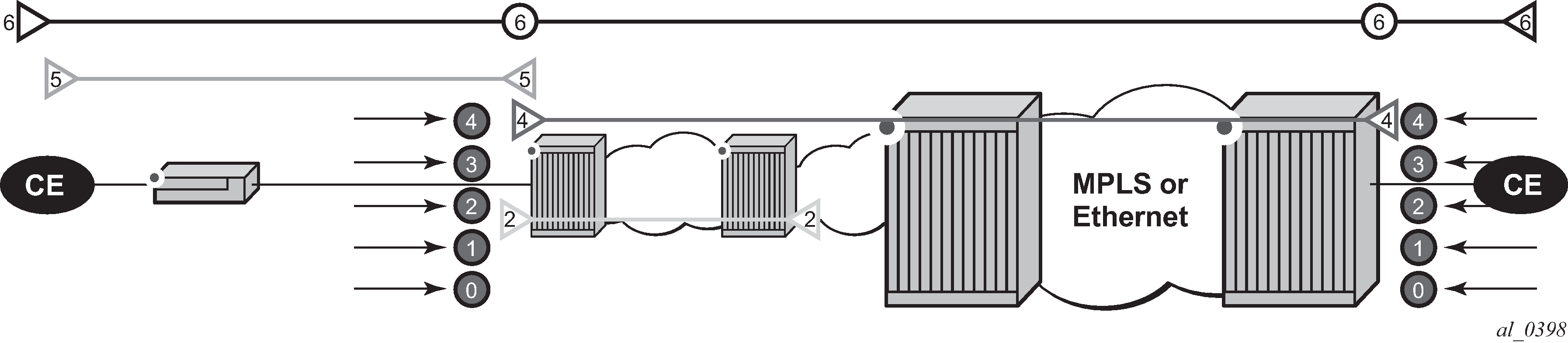
Squelching configuration uses a single MD-level (0 to 7) to silently drop all ETH-CFM packets matching the SAP or binding delimited configuration at or below the specified MD-level. In ETH-CFM hierarchical model, a squelch level is configured at MD-level 4. This means the configuration will silently discard MD-levels 0,1,2,3 and 4, assuming there is a SAP or binding match.
The operator is able to configure down MEPs and ingress MIPs that conflict with the squelched levels. This means that any existing MEP or MIP processing ingress CFM packets on a SAP or binding where a squelching policy is configured will be interrupted as soon as this command is entered into the configuration. These MPs are not able to receive any ingress ETH-CFM frames because squelching is processed before ETH-CFM extraction.
CPU protection extensions for ETH-CFM are still required in the model above because the subscriber ME (6) and the test ME (5) are entering the network across an untrusted connection, the UNI. ETH-CFM squelching and CPU protection for ETH-CFM can be configured on the same SAP or binding. Squelching is processed followed by CPU protection for ETH-CFM.
MPs configured to support primary VLANs are not subjected to the squelch function. Primary VLAN-based MPs, supported only on Ethernet SAPs, are extractions that take into consideration an additional VLAN beyond the SAP configuration.
The difference in the two protection mechanisms is shown in the CPU protection and squelching. CPU protection is used to control access to the CPU resources when processing is required. Squelching is required when the operator is protecting the ETH-CFM architecture from external sources.
| Description | CPU protection extension for ETH-CFM | ETH-CFM squelching |
|---|---|---|
Ingress filtering |
Yes |
Yes |
Egress filtering |
Yes |
— |
Granularity |
Specified level and OpCode |
Level (at and below) |
Rate |
Configurable rate (includes 0=drop all) |
Silent drop |
Primary VLAN support |
Rate shared with SAP delineation |
Not exposed to squelch |
Extraction |
Requires MEP or MIP to extract |
No MEP or MIP required |
show service service-id all
show service sap-using eth-cfm squelch-ingress-levels
show service sdp-using eth-cfm squelch-ingress-levels
show service sap-using squelch-ingress-levels
=========================================================================
ETH-CFM Squelching
=========================================================================
PortId             SvcId      Squelch Level
-------------------------------------------------------------------------
6/1/1:100.*        1          0 1 2 3 4 5 6 7
lag-1:100.*        1          0 1 2 3 4
6/1/1:200.*        2          0 1 2
lag-1:200.*        2          0 1 2 3 4 5
-------------------------------------------------------------------------
Number of SAPs: 4
-------------------------------------------------------------------------
show service sdp-using squelch-ingress-levels
=========================================================================
ETH-CFM Squelching
=========================================================================
 SdpId              SvcId       Type Far End             Squelch Level
-------------------------------------------------------------------------
12345:4000000000   2147483650   Spok 10.1.1.1            0 1 2 3 4
=========================================================================
Distributed CPU protection
Distributed CPU Protection (DCP) is a rate-limiting function distributed to the line cards to rate limit traffic extracted from the datapath and sent to the CPM CPU. DCP is performed in hardware and provides a granular per-interface and per-protocol rate-limit control.
There are two main types of DCP policies for access or network interfaces and ports. The DCP policy defines the protocols and their associated policers. The list of protocols supported depends on the type of DCP policy:
-
access network
This type of DCP policy is used to rate limit interface level protocols and supports policing the following protocols: ARP, DHCP, HTTP redirect, ICMP, ICMP ping check, IGMP, MLD, NDIS, PPPoE-PPPoA, MPLS-TTL, BFD-CPM, BGP, ETH-CFM, IS-IS, LDP, OSPF, PIM, RSVP, VRRP, Multi-Chassis, and Multi-Chassis Sync. traffic from other protocols or unconfigured protocols is classified in the all-unspecified command option in the DCP protocol.
port
This type of DCP policy is used to rate limit the port-level protocols LACP, Dot1X, uBFD, and ELMI. The system supports LACP, BFD-CPM, and ETH-CFM as port-level protocols that can be rate limited individually. Traffic from unconfigured protocols is classified in the all-unspecified command option in the DCP protocol.
Use the following command to classify protocols:
-
MD-CLI
configure system security dist-cpu-protection policy protocol protocol-name -
classic CLI
configure system security dist-cpu-protection policy protocol
A default DCP policy is assigned automatically to all network interfaces, access interfaces, and ports. These policies, ‟_default-access-policy”, ‟_default-network-policy”, and ‟_default-port-policy” are originally created empty and they can be modified by the user. These default policies can be used, for example, to deploy a new DCP configuration covering all access and network interfaces or ports on the node.
Additional DCP policies can be created for interfaces or ports requiring a dedicated configuration.
If the router interface does not need DCP functionality, the user can create and explicitly assign an empty DCP policy to the router interface using the configure router interface dist-cpu-protection command.
Policer
The rate-limits are configured in the DCP policy using either static or dynamic policers and the action for the exceed-action policer command for non-conforming packets can be set to discard, low-priority, or none.
Static policer
Static policers are always instantiated for each endpoint to which the DCP policy is assigned.
The following example provides two simple customized default DCP policies using static policers for access and network interfaces:
-
The access DCP policy is configured to drop all access traffic exceeding 6,000 pps.
-
The network DCP policy marks all traffic exceeding 3,000 pps as low priority except for BGP and LDP (for example, the BGP and LDP can be rate-limited using the per-peer-queuing command).
MD CLI
[ex:/configure system security dist-cpu-protection]
A:admin@node-2# info
    policy "_default-access-policy" {
        protocol all-unspecified {
            enforcement {
                static {
                    policer-name "access"
                }
            }
        }
        static-policer "access" {
            exceed-action {
                action discard
            }
            rate {
                packets {
                    limit 6000
                    within 1
                }
            }
        }
    }
    policy "_default-network-policy" {
        protocol all-unspecified {
            enforcement {
                static {
                    policer-name "network"
                }
            }
        }
        protocol bgp {
            enforcement {
                static {
                    policer-name "null"
                }
            }
        }
        protocol ldp {
            enforcement {
                static {
                    policer-name "null"
                }
            }
        }
        static-policer "network" {
            exceed-action {
                action low-priority
            }
            rate {
                packets {
                    limit 3000
                    within 1
                }
            }
        }
        static-policer "null" {
        }
    }
classic CLI
A:node-2>config>sys>security>dist-cpu-protection# info
------------------------------------------------
                policy "_default-access-policy" create
                    static-policer "access" create
                        rate packets 6000 within 1
                        exceed-action discard
                    exit
                    protocol all-unspecified create
                        enforcement static "access"
                    exit
                exit
                policy "_default-network-policy" create
                    static-policer "null" create
                    exit
                    static-policer "network" create
                        rate packets 3000 within 1
                        exceed-action low-priority
                    exit
                    protocol all-unspecified create
                        enforcement static "network"
                    exit
                    protocol bgp create
                        enforcement static "null"
                    exit
                    protocol ldp create
                        enforcement static "null"
                    exit
                exit
----------------------------------------------
Local monitor and dynamic policer
The use of the local-monitoring-policer command and dynamic policers reduces the number of policers required. This can be particularly useful in a large number of endpoints, such as subscribers in ESM networks. Instead of using multiple static policers for various protocols on each endpoints, a single policer (the local-monitoring policer) is instantiated statically for a specified endpoint and the per-protocol dynamic policers are instantiated when there is a violation of the local-monitoring policer.
Use the following command to instantiate dynamic policers from a pool allocated per line card:
configure card fp ingress dist-cpu-protection dynamic-enforcement-policer-poolThis pool of policers should be greater than the maximum number of dynamic policers expected to be in use on the card at one time.
The following example shows monitoring of the rate of ARP, ICMP, IGMP and all-unspecified traffic. If the total rate exceeds 100 packets within 10 seconds, the system creates three dynamic policers for ARP, ICMP and IGMP to rate-limit each protocol to 20 packets within 10 seconds as well as a fourth policer to rate-limit the rest of the traffic to 100 packets within 10 seconds.
MD-CLI
[ex:/configure system security dist-cpu-protection]
A:admin@node-2# info
    policy "dynamic-policy-example" {
        description "Dynamic policing policy"
        protocol arp {
            enforcement {
                dynamic {
                    mon-policer-name "local-mon"
                }
            }
            dynamic-parameters {
                exceed-action {
                    action discard
                }
                rate {
                    packets {
                        limit 20
                        within 10
                    }
                }
            }
        }
        protocol icmp {
            dynamic-parameters {
                exceed-action {
                    action discard
                }
                rate {
                    packets {
                        limit 20
                        within 10
                    }
                }
            }
        }
        protocol igmp {
            enforcement {
                dynamic {
                    mon-policer-name "local-mon"
                }
            }
            dynamic-parameters {
                exceed-action {
                    action discard
                }
                rate {
                    packets {
                        limit 20
                        within 10
                    }
                }
            }
        }
        protocol all-unspecified {
            enforcement {
                dynamic {
                    mon-policer-name "local-mon"
                }
            }
            dynamic-parameters {
                exceed-action {
                    action discard
                }
                rate {
                    packets {
                        limit 100
                        within 10
                    }
                }
            }
        }
        local-monitoring-policer "local-mon" {
            description "Monitor for arp, icmp, igmp, and all-unspecified"
            rate {
                packets {
                    limit 100
                    within 10
                }
            }
        }
    }
classic CLI
A:node-2>config>sys>security>dist-cpu-protection# info
------------------------------------------------
                policy "dynamic-policy-example" create
                    description "Dynamic policing policy"
                    local-monitoring-policer "local-mon" create
                        description "Monitor for arp, icmp, igmp and all-unspecified"
                        rate packets 100 within 10
                    exit
                    protocol arp create
                        enforcement dynamic "local-mon"
                        dynamic-parameters
                            rate packets 20 within 10
                            exceed-action discard
                        exit
                    exit
                    protocol icmp create
                        enforcement dynamic "local-mon"
                        dynamic-parameters
                            rate packets 20 within 10
                            exceed-action discard
                        exit
                    exit
                    protocol igmp create
                        enforcement dynamic "local-mon"
                        dynamic-parameters
                            rate packets 20 within 10
                            exceed-action discard
                        exit
                    exit
                    protocol all-unspecified create
                        enforcement dynamic "local-mon"
                        dynamic-parameters
                            rate packets 100 within 10
                            exceed-action discard
                        exit
                    exit
                exit
----------------------------------------------
Applicability
For the access interface, most types of SAPs on Layer 2 and Layer 3 services are supported including capture SAPs, SAPs on pseudowires, B-VPLS SAPs, and VPLS template SAPs, but are not applicable to Epipe template SAPs and video ISA SAPs.
Control packets that are extracted in a VPRN service, where the packets arrived into the node through a VPLS SAP (that is, R-VPLS scenario), use the DCP policy and policer instances associated with the VPLS SAP. For VPLSs that have a Layer 3 interface bound to them, (R-VPLS), protocols such as OSPF and ARP may be configured in the DCP policy.
Control traffic that arrives on a network interface, but inside a tunnel (for example, SDP, LSP, PW) and logically terminates on a service (that is, traffic that is logically extracted by the service instead of the network interface layer itself) bypass the DCP function. The control packets are not subject to the DCP policy that is assigned to the network interface on which the packets arrived. This helps to avoid customer traffic in a service from impacting other services or the operator's infrastructure.
Log events, statistics, status, and SNMP support
Log events are supported for DCP to alert the operator to potential attacks or misconfigurations. DCP throttles the rate of events to avoid event floods when multiple parallel attacks or problems. You can enable or disable log events individually at the DCP policy level, as well as globally in the system. Use the commands in the following context to enable logs globally:
- MD-CLI
configure log log-events - classic
CLI
configure log event-control
Use the following command to display the additional statistics for the packet exceed count and policer state.
show router interface dist-cpu-protectionUse tools commands, such as the following, to identify interface violators.
tools dump security dist-cpu-protection violatorsFor SNMP support, see the tables and MIB objects with ‟Dcp” or ‟DCpuProt” in their name. These can be found in the following MIBs:
TIMETRA-CHASSIS-MIB
TIMETRA-SECURITY-MIB
TIMETRA-SAP-MIB
TIMETRA-VRTR-MIB
DCP policer resource management
The policer instances are a limited hardware resource on a specific forwarding plane. DCP policers (static, dynamic, local-monitor) are consumed from the overall forwarding plane policer resources (from the ingress resources if ingress and egress are partitioned). Each per-protocol policer instantiated reduces the number of FP child policers available for other purposes.
When DCP is configured with dynamic enforcement, then the operator must set aside a pool of policers that can be instantiated as dynamic enforcement policers. The number of policers reserved for this function are configurable per card or FP. The policers in this pool are not available for other purposes (normal SLA enforcement).
Static enforcement policers and local monitoring policers use policers from the normal or global policer pool on the card or FP. After a static policer is configured in a DCP policy and it is referenced by a protocol in the policy, this policer will be instantiated for each object (SAP or network interface) that is created and references the policy. If there is no policer free on the associated card or FP, then the object will not be created. Similarly, for local monitors, after a local monitoring policer is configured and referenced by a protocol, then this policer will be instantiated for each object that is created and references the policy. If there is no policer free, then the object will not be created.
Dynamic enforcement policers are allocated as needed (when the local monitor detects nonconformance) from the reserved dynamic enforcement policer pool.
When a DCP policy is applied to an object on a LAG, then a set of policers is allocated on each FP (on each line card that contains a member of the LAG). The LAG mode is ignored and the policers are always shared by all ports in the LAG on that forwarding plane on the SAP or interface. In other words, with link-mode lag a set of DCP policers are not allocated per-port in the LAG on the SAP.
To support large scale operation of DCP, and also to avoid overload conditions, a polling process is used to monitor state changes in the policers. This means there can be a delay between when an event occurs in the data plane and when the relevant state change or event notification occurs toward an operator, but in the meantime the policers are still operating and protecting the control plane.
Operational guidelines and tips
The following points offer various optional guidelines that may help an operator decide how to leverage Distributed CPU Protection.
The rates in a policy assigned to a capture SAP should be higher than those assigned to MSAPs that will contain a single subscriber. The rates for the capture sap policy should allow for a burst of MSAP setups.
To completely block a set of specific protocols on a specific SAP, create a single static policer with a rate of 0 and map the protocols to that policer. Dynamic policers and local monitors cannot be used to simultaneously allow some protocols but block others (the non-zero rates in the monitor would allow all protocols slip through at a low rate).
During normal operation it is recommended to configure ‟log-events” (no verbose keyword) for all static policers, in the dynamic parameters of all protocols and for all local monitoring policers. The verbose keyword can be used selectively during debug, testing, tuning, and investigations.
Packet-based rate limiting is generally recommended for low-rate subscriber-based protocols whereas kb/s rate limiting is recommended for higher rate infrastructure protocols (such as BGP).
It is recommended to configure an exceed-action of low-priority for routing and infrastructure protocols. Marked packets are more likely to be discarded if there is congestion in the control plane of the router, but will get processed if there is no contention for CPU resources allowing for a work-conserving behavior in the CPM.
To assign a different distributed CPU protection policy to a specific MSAP instance or to all MSAPs for a specific MSAP policy, assign the new policy and then use one of the following tools commands:
tools perform subscriber-mgmt eval-msap policy policy-name
tools perform subscriber-mgmt eval-msap msap sap-id
Note: The new dist-cpu-protection policy is also assigned to new MSAPs.Use the following command if needed to determine which subscriber is on a specific MSAP and then filter (‟| match”) on the MSAP string.
show service active-subsIf protocol is trusted, and using the ‟all-unspecified” protocol is not required, then avoid referencing this protocol in the policy configuration.
If a protocol is trusted, but the all-unspecified bucket is required, there are two options:
Avoid creating a protocol so that it is treated as part of the all-unspecified bucket (but account for the packets from X in the all-unspecified rate and local-mon rate).
Create this protocol and configure it to bypass.
Classification-based priority for extracted protocol traffic
The SR OS supports a set of mechanisms to protect the router control and management planes from various types of attacks, floods, and misconfigurations. Many of the mechanisms operate by default with no need for operator configuration or intervention.
One class of mechanisms employed on the router to protect against floods of control traffic involves identifying potentially harmful or malicious traffic through the use of rate measurements. Centralized CPU protection protects and isolates interfaces from each other by default by treating unexpectedly high rate control traffic on an interface as lower priority (to be discarded if the control plane experiences congestion). Distributed CPU protection can protect and isolate at a per-protocol, per-interface granularity through configured rate profiles. These rate-based protection mechanisms make no assumptions about the contents of the packets and can be used when nothing about the packets can be trusted (for example, DSCP or source IP address, which can be spoofed).
The SR OS also supports an alternative to rate-based mechanisms for cases where the packet headers can be trusted to differentiate between good and bad control traffic. A configurable prioritization scheme can be enabled (using the init-extract-prio-mode l3-classify command) on a per-FP basis to initialize the drop priority of all Layer 3 extracted control traffic based on the QoS classification of the packets. This is useful, for example, in networks where the DSCP and EXP markings can be trusted as the primary method to distinguish, protect, and isolate good terminating protocol traffic from unknown or potentially harmful protocol traffic, instead of using rate-based distributed CPU protection and centralized CPU protection traffic marking and coloring mechanisms such as the out-profile-rate or exceed-action commands with the action set to low-priority.
The following are the operational guidelines for deploying classification-based priority for extracted control traffic:
Centralized CPU protection should be effectively disabled for all interfaces/SAPs on FPs configured in l3-classify mode by changing some CPU protection policy parameters from their default values. This is required so that centralized CPU protection does not re-mark good control traffic (traffic that was initially classified as high priority) as low priority if a flood attack occurs on the same interface. Effectively disabling centralized CPU protection can be done by ensuring the following:
a rate value of max is configured for port-overall-rate command (max is the default value for port-overall-rate command)
all objects (interfaces, MSAP policies, and SAPs) that can be assigned a CPU protection policy are referencing a policy that sets the out-profile-rate command to max and the overall-rate command to max (this can be done in the two default CPU protection policies if all FPs in the system are in l3-classify mode)
DCP can be used in conjunction with l3-classify mode, but care must be taken to prevent DCP from acting on protocols where the operator wants to use QoS classification (such as DSCP or EXP) to differentiate between good and bad Layer 3 packets. On an FP with l3-classify mode, configure DCP so that BGP, LDP, and other protocols do not have their initial drop priority (color) overwritten by DCP if the QoS classification of these protocols is trusted. To achieve this, use none as the action for the exceed-action command, for those protocols in the DCP policy. For other protocols where QoS classification cannot be used to distinguish between good and bad extracted packets, use DCP to color the packets with a drop priority based on a configured rate.
If any LAG member is on an FP in l3-classify mode, all FPs that host the other members of that LAG should also be in l3-classify mode.
The QoS classification rules that are used on interfaces and SAPs on FPs in l3-classify mode should be configured to differentiate between good and bad control traffic. The default network ingress QoS policies do differentiate (for example, based on DSCP), however the default access ingress QoS policies do not.
The l3-classify mode for extracted control traffic is supported on the 7750 SR and 7950 XRS.
TTL security
The SR OS TTL security evaluates the value of the incoming packets against a maximum TTL value configured in the system. This capability, also known as Generalized TTL Security Mechanism (GTSM) defined in RFC 5082, is supported for BGP, LDP, SSH and Telnet. If the incoming TTL value is less than the configured TTL value, the packets are discarded and a log is generated preventing attackers generating spoof traffic with larger number of hops than expected.
The TTL value is configurable on a per-peer basis for BGP and LDP and configurable at the system level for SSH and Telnet.
The TTL security mechanism was originally designed to protect the BGP infrastructure where the vast majority of ISP External Border Gateway Protocol (EBGP) peerings are established between adjacent routers. Because TTL spoofing cannot be performed, a mechanism based on an expected TTL value provides a simple and robust defense from infrastructure attacks based on forged BGP packets.
While TTL security is most effective in protecting directly-connected BGP or LDP peers, it can also provide protection to multi-hop sessions. For multi-hop sessions the expected TTL value can be set to 255 minus the configured range of hops.
Management Access Filter
The CPM CPU uses Management Access Filter (MAF) filters to perform filtering that applies to both traffic from the line cards directed to the CPM CPU as well as traffic from the management Ethernet port.
MAF filter packet match
You can configure three different management-access filter policies: IP filter, IPv6 filter, and MAC filter. Each policy is an ordered list of entries. For this reason, you must sequence the entries correctly from the most to the least explicit.
Management Access filter (MAF) packet match rules:
Each MAF policy is an ordered list of entries, therefore entries must be sequenced correctly from the most to the least explicit.
If multiple match criteria are specified in a single MAF filter policy entry, all criteria must be met for the packet to be considered a match against that policy entry (logical AND).
Any match criteria not explicitly defined is ignored during a match.
A MAF filter policy entry with match criteria defined, but no action configured, inherits the default action.
The default action for the management-access-filter filter entry applies individually per IPv4, IPv6, or MAC CPM filter policies that are in an enabled state.
When both mac-filter and ip-filter or ipv6-filter are applied to a specific packet, the mac-filter is applied first.
MAF IPv4/IPv6 filter entry match criteria
IPv4 and IPv6 match criteria lists the supported IPv4 and IPv6 match criteria.
| Criteria | Description |
|---|---|
src-ip |
Matches the specified source IPv4 or IPv6 address prefix and mask against the source IPv4 or IPv6 address field in the IP packet header. IPv4 and IPv6 matching prefix-lists can be used to enhance matching capabilities. |
next-header |
Matches the specified upper-layer protocol (such as TCP, UDP, or IGMPv6) against the next-header field of the IPv6 packet header. "*" can be used to specify a TCP or UDP upper-layer protocol match (Logical OR). Next-header matching allows also matching on presence of a subset of IPv6 extension headers. See the CLI section for details on which extension header match is supported. |
protocol |
Matches the specified protocol against the Protocol field in the IPv4 packet header (for example, TCP, UDP, or IGMP) of the outer IPv4. "*" can be used to specify TCP or UDP upper-layer protocol match (Logical OR). |
dst-port |
Matches the specified port value against the destination port number of the UDP or TCP packet header. |
flow-label |
Matches the IPv6 flow label. |
|
router instance |
Matches the router instance packets that are ingressing from for this filter entry. |
src-port |
Matches the port packets that are ingressing from for this filter entry. |
MAF MAC filter entry match criteria
Router instance match criteria describes the supported MAC match criteria. The criteria are evaluated against the Ethernet header of the Ethernet frame.
| Criteria | Description |
|---|---|
frame-type |
Matches a specific type of frame format. |
src-mac |
Matches the specified source MAC address frames. Optionally, operators can configure a mask to be used in a match. |
dst-mac |
Matches the specified destination MAC address frames. Optionally, operators can configure a mask to be used in a match. |
dot1p |
Matches 802.1p frames. Optionally, operators can configure a mask to be used in a match. |
etype |
Matches the specified Ethernet II frames. The Ethernet type field is a two-byte field used to identify the protocol carried by the Ethernet frame. |
snap-oui |
Matches frames with the specified three-byte OUI field. |
snap-pid |
Matches frames with the specified two-byte protocol ID that follows the three-byte OUI field. |
ssap |
Matches the specified frames with a source access point on the network node designated in the source field of the packet. Optionally, operators can configure a mask to be used in a match. |
dsap |
Matches the specified frames with a destination access point on the network node designated in the destination field of the packet. Optionally, operators can configure a mask to be used in a match. |
CFM opcode |
Matches the specified packet with the specified CFM opcode. |
service ID |
Matches the service ID packets are ingressing from. |
service name |
Matches the service name packets are ingressing from. |
MAF filter policy action
Management-access filter policies allow permit or deny traffic configuration (or use deny-host-unreachable response for IP filters).
permit
MAF filter policy statistics and logging
Management access filter match count can be displayed using show commands. Logging is recorded in the system security logs.
Vendor-specific attributes
The software supports the configuration of Nokia-specific RADIUS attributes. These attributes are known as vendor-specific attributes (VSAs) and are discussed in RFC 2138. The RADIUS user authenticates with parameters defined in the default RADIUS user template if VSAs are not configured in the RADIUS server. If VSAs are configured, all mandatory VSAs must be configured for the RADIUS user to authenticate. It is up to the vendor to specify the format of their VSA. The attribute-specific field is dependent on the vendor's definition of that attribute. The Nokia-defined attributes are encapsulated in a RADIUS vendor-specific attribute with the vendor ID field set to 6527, the vendor ID number. For a full list of Nokia VSAs, see the dictionary-freeradius.txt file in the support folder of the software distribution.
The following RADIUS vendor-specific attributes (VSAs) are supported by Nokia.
Timetra-Access <ftp> <console> <both><netconfig><grpc>
This is a mandatory VSA that specifies if the user has FTP, console (serial port, Telnet, and SSH), NETCONF, or gRPC access.
Timetra-Profile <string>
When configuring this VSA for a user, it is assumed that the user profiles are configured on the local router and the following applies for local and remote authentication:
The authentication-order parameters configured on the router must include the local keyword.
The username may or may not be configured on the router.
The user must be authenticated by the RADIUS server.
Up to 8 valid profiles can exist on the router for a user. The sequence in which the profiles are specified is relevant. The most explicit matching criteria must be ordered first. The process stops when the first complete match is found.
If all the above mentioned conditions are not met, then access to the router is denied and a failed login event/trap is written to the security log.
Timetra-Default-Action <permit-all | deny-all | none>
This is a mandatory VSA that must be configured even if the Timetra-Cmd VSA is not used. This command specifies the default action when the user has entered a command and no entry configured in the Timetra-Cmd VSA for the user resulted in a match condition.
Timetra-Cmd <string>
This VSA configures a command or command subtree as the scope for the match condition.
The command and all subordinate commands in subordinate command levels are specified.
-
Timetra-Home-Directory <string>
This VSA specifies a user's home directory.
-
Timetra-Restrict-To-Home <true | false>
When this VSA is set to true, the user's file system access is restricted to the home directory specified with Timetra-Home-Directory.
Other security features
This section describes the other security features supported by the SR OS.
SSH
Secure Shell (SSH) is a protocol that provides a secure, encrypted Telnet-like connection to a router. A connection is always initiated by the client (the user). Authentication uses one of the configured authentication methods (local, RADIUS, TACACS+, or LDAP). With authentication and encryption, SSH allows for a secure connection over an insecure network.
SR OS supports SSH version 2 (SSHv2) only. When a configuration contains SSHv1, SSHv1 is deprecated from the configuration, and the configuration migrates to SSHv2 using the default cipher list.
SSH runs on top of a transport layer (like TCP or IP) and provides authentication and encryption capabilities.
SR OS has a global SSH server process to support inbound SSH, SFTP, NETCONF, and SCP sessions initiated by external client applications. This server process is separate from the SSH and SCP client commands on the routers which initiate outbound SSH and SCP sessions.
Inbound SSH, Telnet, and FTP sessions are counted separately. Use the following command to set the limit for each type separately.
configure system login-controlHowever, there is a maximum total of 50 sessions for SSH and Telnet together. SCP, SFTP, and NETCONF sessions are counted as SSH sessions.
When the SSH server is enabled, an SSH security key is generated. Unless the preserve-key command option is configured for SSH, the security key is only valid until the node is restarted or the SSH server is stopped and restarted. The key size is non-configurable and set to 2048 for SSHv2 RSA, and to 1024 for SSHv2 DSA and SSHv1 RSA1. Only SSHv2 RSA is supported in FIPS mode. When the server is enabled, all inbound SSH, SCP, SFTP, and NETCONF sessions will be accepted provided the session is properly authenticated.
When the global SSH server process is disabled, no inbound SSH, SCP, SFTP, or NETCONF sessions are accepted.
When using SCP to copy files from an external device to the file system, the SCP server accepts either forward slash (‟/”) or backslash (‟\”) characters to delimit directory and filenames. Similarly, the SCP client application can use either slash or backslash characters, but not all SCP clients treat backslash characters as equivalent to slash characters. In particular, UNIX systems can interpret the backslash character as an ‟escape” character which is not transmitted to the SCP server. For example, a destination directory specified as ‟cf1:\dir1\file1” is transmitted to the SCP server as ‟cf1:dir1file1”, where the backslash escape characters are stripped by the SCP client system before transmission. On systems where the client treats the backslash like an ‟escape” character, a double backslash ‟\\” or the forward slash ‟/” can be used to properly delimit directories and the filename.
There are three pairs of configurable lists: cipher lists, MAC lists, and KEX lists. In each pair, one list is dedicated to the SSH server, and a second list is dedicated to the SSH/SCP client. These can be configured for negotiation of the best compatible cipher, MAC, and KEX algorithm between the client and server. The lists can be created and managed under the security sshcontext. The client lists are used when the SR OS is acting as the SSH client and the server lists are used when the SR OS is acting as a server. The first algorithm matched on the lists between the client and server is the preferred algorithm for the session.
- password
- keyboard-interactive
- public key
SR OS SSH supports multichannel within a single connection. The primary connection authenticates the user through PKI or keyboard authentication. After the primary connection is authenticated, applications like NETCONF can open multiple channel "sessions" to the server with the same connection. Currently, NETCONF and CLI can open multiple channels in the same connection. Each connection can have five channels for a maximum of 50 channels per system.
SSH PKI authentication
The SSH server also supports a public key authentication as long as the server has been previously configured to know the client's public key.
Using Public Key authentication (also known as Public Key Infrastructure - PKI) can be more secure than the existing username and password method because of the following reasons.
A user typically re-uses the same password with multiple servers. If the password is compromised, the user must reconfigure the password on all affected servers.
A password is not transmitted between the client and server using PKI. Instead the sensitive information (the private key) is kept on the client. Therefore the password is less likely to be compromised.
SR OS supports server-side SSHv2 public key authentication but does not include a key-generation utility.
Support for PKI should be configured in the system-level configuration where one or more public keys may be bound to a username. This configuration does not affect any other system security or login functions.
PKI has preference over password or keyboard authentication. PKI is supported using local authentication and using an AAA server with LDAP only. PKI authentication is not supported on TACACS+ or RADIUS, and users with public keys always use local authentication only.
User public key generation
Before you can use SSH with PKI, you must generate a public and private key pair. This is typically supported by the SSH client software. For example, PuTTY supports a utility called PuTTYGen that generates key pairs.
SR OS currently supports only RSA and ECDSA user public keys.
If using PuTTY, first generate a key pair using PuTTYGen, set the key type to SSH-2 RSA, and specify the number of bits to use for the key. You can also configure a passphrase to use to store the key locally in encrypted form. If configured, the passphrase acts as a password that you must enter to use the private key. If you do not use a passphrase, the key is stored in plain text locally.
Use the following command to configure the public key for the user on SR OS:
- MD-CLI
configure system security user-params local-user user public-keys - classic
CLI
configure system security user public-keys
On SR OS, you can program the public key using Telnet/SSH or SNMP.
Multichannel SSH
SR OS supports opening up to five channels per SSH connection. SSH channels can be used when an SSH connection has authenticated a user and a channel is opened for configuration while another channel is required to retrieve state information, such as collecting configurations or show command output. In this case, some network managers attempt to set up an additional channel in the existing SSH connection.
Opening a new channel inside an existing authenticated SSH connection mitigates the additional time and memory requirements for establishing a new SSH session. This mitigation is useful when, for example, multiple RPCs from different network manager users to the same device are executed at the same time.
Multiple channels are only supported for SSH and some applications that use SSH as transport. Multiple channels are not supported for SFTP or SCP.
MAC client and server list
SR OS supports a configurable server and client MAC list for SSHv2. This allows the user to add or remove MAC algorithms from the list. The user can program the strong HMAC algorithms on top of the configurable MAC list (for example, lowest index in the list) in the order to be negotiated first between the client and server. The first algorithm in the list that is supported by both the client and the server is the one that is agreed upon.
There are two configurable MAC lists:
-
server list
-
client list
The default MAC list includes all supported algorithms with the following preference:
-
mac 200 name hmac-sha2-512
-
mac 210 name hmac-sha2-256
-
mac 215 name hmac-sha1
-
mac 220 name hmac-sha1-96
-
mac 225 name hmac-md5
-
mac 240 name hmac-md5-96
KEX client and server list
SR OS supports KEX client and server lists. The user can remove or add the needed KEX client/server algorithms to be negotiated using an SSHv2 phase one handshake. The list is an index list with the lower index having higher preference in the SSH negotiation. The lowest index algorithm in the list will be negotiated first in SSH and will be on top of the negotiation list to the peer.
By default the KEX list is empty and this hard-coded list with all supported algorithms and the following preference is used:
kex 200 name diffie-hellman-group16-sha512
kex 210 name diffie-hellman-group14-sha256
kex 215 name diffie-hellman-group14-sha1
kex 220 name diffie-hellman-group-exchange-sha1
kex 225 name diffie-hellman-group1-sha1
As soon as an algorithm is configured in the KEX list, the SR OS starts using the user-defined KEX list instead of the hard-coded list.
To go back to the hard-coded list, you must remove all configured KEX indexes until the list is empty. Use the following commands inline with cipher/mac server/client lists:
- MD-CLI
configure system security ssh client-kex-list-v2 kex configure system security ssh client-kex-list-v2 delete kex configure system security ssh server-kex-list-v2 kex configure system security ssh server-kex-list-v2 delete kex - classic
CLI
configure system security ssh client-kex-list kex
configure system security ssh client-kex-list no kex
configure system security ssh server-kex-list kex
configure system security ssh server-kex-list no kex
Regenerate the SSH key without disabling SSH
SR OS supports periodic rollover of the SSH symmetric key. Symmetric key rollover is important in long SSH sessions. Symmetric key rollover ensures that the encryption channel between the client and server is not jeopardized by an external hacker that is trying to break the encryption via a brute force attack.
This feature introduces symmetric key rollover on SSH client or server. The following are triggers for symmetric key rollover and negotiation:
the negotiation of the key base on a configured time period
the negotiation of the key base on a configured data transmission size
For extra security, by default the key re-exchange is enabled under SR OS.
Key re-exchange procedure
Key re-exchange is started by sending an SSH_MSG_KEXINIT packet while not already doing a key exchange. When this message is received, a party must respond with its own SSH_MSG_KEXINIT message, except in cases where the received SSH_MSG_KEXINIT already was a reply. Either party may initiate the re-exchange, but roles must not be changed (for example, the server remains the server, and the client remains the client).
Key re-exchange is performed using whatever encryption was in effect when the exchange was started. Encryption, compression, and MAC methods are not changed before a new SSH_MSG_NEWKEYS is sent after the key exchange (as in the initial key exchange). Re-exchange is processed identically to the initial key exchange, except that the session identifier remains unchanged. Some or all of the algorithms can be changed during the re-exchange. Host keys can also change. All keys and initialization vectors are recomputed after the exchange. Compression and encryption contexts are reset.
RFC 4253 recommends key exchange after every hour or 1Gbytes of transmitted data, which is met by SR OS default implementation.
SR OS can roll over keys via two mechanisms:
bytes (default is 1 Gbyte and the keys are negotiated)
minutes (default is 1 minute)
If both the bytes and minutes key rollover mechanisms are configured, the key rollover happens based on whichever occurs first.
If these parameters change, only new SSH connections inherit them. The existing SSH connections continue to use the previously configured parameters.
Cipher client and server list
SR OS supports cipher client and server lists. The user can add or remove the needed SSH cipher client and server algorithms to be negotiated. The list is an index list with the lower index having higher preference in the SSH negotiation. The lowest index algorithm in the list is negotiated first in SSH and is on top of the negotiation list to the peer.
The default server and client lists for SSHv2 include all supported algorithms with the following preference:
-
cipher 190 name aes256-ctr
-
cipher 192 name aes192-ctr
-
cipher 194 name aes128-ctr
-
cipher 200 name aes128-cbc
-
cipher 205 name 3des-cbc
-
cipher 225 name aes192-cbc
-
cipher 230 name aes256-cbc
SSH session closing behavior
The SSH session closes automatically when the channel opened last in the session is closed.
SSH keepalive intervals are disabled on SR OS, which means the following:
- The SR OS SSH server does not close the session when the client SSH keepalive intervals time out.
- The client SSH keepalive intervals cannot be used to keep the connection to the SR OS server open.
CLI and SNMP considerations
Support for SSH version 1 (SSHv1) has been removed from SR OS. The following considerations apply when upgrading from a pre-22.10 release.
Classic CLI
configure system security ssh versionThe preceding command has the following behaviors:
- The default is 2. If a configuration is loaded that contains SSH version 1, it is ignored and the default is 2.
- If the version is set to 1-2, the router functions as if the version is set to 2.
The following commands configure the protocol version:
configure system security ssh client-cipher-list protocol-version
configure system security ssh server-cipher-list protocol-version- Setting the protocol version to 1 is blocked (entering the container is blocked).
- All ciphers are blocked for protocol version 1.
The following commands set the protocol version to 2:
configure system security ssh client-cipher-list protocol-version 2
configure system security ssh server-cipher-list protocol-version 2
The preceding commands have the following ciphers blocked:
- cast128-cbc
- arcfour
- blowfish-cbc
- rijndael-cbc
configure system security ssh client-mac-list
configure system security ssh server-mac-list
The preceding commands have the following ciphers blocked:
- hmac-ripemd160-openssh-com
- hmac-ripemd160
The following applies to the blocked commands:
- They are silently ignored when executing a configuration file.
- Attempting to execute them in an interactive CLI configuration returns an error.
An In-Service Software Upgrade (ISSU) conversion must be performed to filter previously existing ciphers and set the SSH version to 2. The customers using version 1 are switched to version 2 with default ciphers and HMAC algorithms. The default cipher set is auto-created.
SNMP
All SNMP objects remain intact. Although SSH version 1 is not visible in the info or show commands, the SNMP objects are present in the MIB and cannot be set. Attempting to configure blocked version 2 ciphers or version 1 settings returns an error.
Exponential login backoff
A malicious user may attempt to gain CLI access by means of a dictionary attack using a script to automatically attempt to login as an ‟admin” user and using a dictionary list to test all possible passwords. Using the exponential-back off feature in the configure system login-control context the OS increases the delay between login attempts exponentially to mitigate attacks.
When a user tries to login to a router using a Telnet or an SSH session, there are a limited number of attempts allowed to authenticate a user. The interval between the unsuccessful attempts change after each try (1, 2 and 4 seconds). If the system is configured for user lockout, then the user will be locked out when the number of attempts is exceeded.
However, if lockout is not configured, there are three password entry attempts allowed after the first failure, at fixed 1, 2 and 4 second intervals, in the first session, and then the session terminates. Users do not have an unlimited number of login attempts per session. After each failed authentication attempt, the wait period becomes longer until the maximum number of attempts is reached.
The OS terminates after four unsuccessful tries. A wait period is never longer than four seconds. The periods are fixed and restart in subsequent sessions.
Use the following system-wide configuration commands together to mitigate attacks:
- MD-CLI
configure system login-control exponential-backoff configure system security user-params attempts - classic
CLI
configure system login-control exponential-backoff
configure system security password attempts
Exponential backoff applies to any user and by any login method such as console, SSH, and Telnet.
For more information, see Configuring login controls.
User lockout
When a user exceeds the maximum number of attempts allowed (the default is 3 attempts) during a specific period of time (the default is 5 minutes), the account used during those attempts are locked out for a pre-configured lock-out period (the default is 10 minutes).
A security or LI event log is generated as soon as a user account has exceeded the number of allowed attempts. Use the following command to display the total number of failed attempts per user.
show system security userIn addition to the security or LI event log, an SNMP trap is also generated so that any SNMP server (including the NSP NFM-P) can use the trap for an action. The account is automatically re-enabled as soon as the lock-out period has expired.
Use the following command to display a list of users who are currently locked out.
show system security user lockoutUse the following command with the applicable option to clear a lockout for a specific user or all users:
- MD-CLI
admin clear security lockout - classic
CLI
admin clear lockout
CLI login scripts
The SR OS supports automatic execution of CLI scripts when a user successfully logs into the router and starts a CLI session.
Use the following command to configure a login script for users who authenticate using the local user database:
- MD-CLI
configure system security user-params local-user user console login-exec file-url - classic
CLI
configure system security user console login-exec file-url
You can configure a global login-script to execute a common script when any user logs into the CLI. You can also configure a per-user login-script to execute when a specific user logs into the CLI. These login-scripts execute when the user is authenticated using the local user database, TACACS+,or RADIUS.
Use the following command to configure a global login script:
- MD-CLI
configure system login-control login-scripts global-script global-login-script-url - classic
CLI
configure system login-control login-scripts global global-login-script-url
Use the following command to configure a user-specific login script pointing to a user-defined directory:
- MD-CLI
configure system login-control login-scripts per-user-script user-directory dir-url - classic
CLI
configure system login-control login-scripts per-user user-directory dir-url file-name file-name
802.1x network access control
The SR OS supports network access control of client devices (PCs, STBs, and so on) on an Ethernet network using the IEEE. 802.1x standard. 802.1x is known as Extensible Authentication Protocol (EAP) over a LAN network or EAPOL.
TCP Enhanced Authentication Option
The TCP Enhanced Authentication Option, currently covered in RFC 5925, The TCP Authentication Option, extends the previous MD5 authentication option to include the ability to change keys without tearing down the session, and allows for stronger authentication algorithms to be used.
The TCP Enhanced Authentication Option is a TCP extension that enhances security for BGP, LDP and other TCP-based protocols. This includes the ability to change keys in a BGP or LDP session seamlessly without tearing down the session. It is intended for applications where secure administrative access to both the end-points of the TCP connection is normally available.
TCP peers can use this extension to authenticate messages passed between one another. This strategy improves upon current practice, which is described in RFC 2385, Protection of BGP Sessions via the TCP MD5 Signature Option. Using this new strategy, TCP peers can update authentication keys during the lifetime of a TCP connection. TCP peers can also use stronger authentication algorithms to authenticate routing messages.
Packet formats
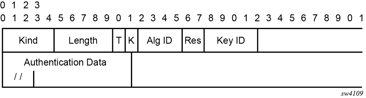
Option Syntax:
-
Kind: 8 bits
The Kind field identifies the TCP Enhanced Authentication Option. This value is assigned by IANA.
-
Length: 8 bits
The Length field specifies the length of the TCP Enhanced Authentication Option, in octets. This count includes two octets representing the Kind and Length fields.
The valid range for this field is from 4 to 40 octets, inclusive.
For all algorithms specified in this memo the value is 16 octets.
-
T-Bit: 1 bit
The T-bit specifies whether TCP Options were omitted from the TCP header for the purpose of MAC calculation. A value of 1 indicates that all TCP options other than the Extended Authentication Option were omitted. A value of 0 indicates that TCP options were included.
The default value is 0.
-
K-Bit: 1 bit
This bit is reserved for future enhancement. Its value must be equal to zero.
-
Alg ID: 6 bits
The Alg ID field identifies the MAC algorithm.
-
Res: 2 bits
These bits are reserved. They must be set to zero.
Key ID: 6 bits
The Key ID field identifies the key that was used to generate the message digest.
-
Authentication Data: Variable length
-
The Authentication Data field contains data that is used to authenticate the TCP segment. This data includes, but need not be restricted to, a MAC. The length and format of the Authentication Data Field can be derived from the Alg ID.
-
The Authentication for TCP-based Routing and Management Protocols draft provides and overview of the TCP Enhanced Authentication Option. The details of this feature are described in draft-bonica-tcp-auth-04.txt.
Keychain
The keychain mechanism allows for the creation of keys used to authenticate protocol communications. Each keychain entry defines the authentication attributes to be used in authenticating protocol messages from remote peers or neighbors, and it must include at least one key entry to be valid. Through the use of the keychain mechanism, authentication keys can be changed without affecting the state of the associated protocol adjacencies for OSPF, IS-IS, BGP, LDP, and RSVP-TE.
Each key within a keychain must include the following attributes for the authentication of protocol messages:
key identifier
authentication algorithm
authentication key
direction
start time
In addition, additional attributes can be optionally specified, including:
end time
tolerance
Keychain mapping shows the mapping between these attributes and the CLI command to set them.
| Definition | CLI |
|---|---|
The key identifier expressed as an integer (0...63) |
|
Authentication algorithm to use with key[i] |
|
Shared secret to use with key[i] |
Use the shared secret with the following:
|
A vector that determines whether the key[i] is to be used to generate MACs for inbound segments, outbound segments, or both. |
|
|
Start time from which key[i] can be used. |
|
End time after which key[i] cannot be used by sending TCPs. |
Inferred by the begin-time of the next key (youngest key rule). |
Start time from which key[i] can be used. |
|
End time after which key[i] cannot be used |
|
Security algorithm support per protocol lists the authentication algorithms that can be used in association with specific routing protocols.
| Protocol | Clear text | MD5 | HMAC-MD5 | HMAC-SHA-1-96 | HMAC-SHA-1 | HMAC-SHA-256 | AES-128-CMAC-96 |
|---|---|---|---|---|---|---|---|
OSPF |
Yes |
Yes |
— |
Yes |
Yes |
Yes |
— |
IS-IS |
Yes |
— |
Yes |
— |
Yes |
Yes |
— |
RSVP |
Yes |
— |
Yes |
— |
Yes |
— |
— |
BGP |
— |
Yes |
— |
Yes |
— |
— |
Yes |
LDP |
— |
Yes |
— |
Yes |
— |
— |
Yes |
gRPC authentication
gRPC communication between the client and server must be authenticated and encrypted. There are two types of authentication:
Authentication via session credentials
Session credentials operate similarly to device authentication, ensuring that the device is allowed in the network and is authorized by the provider. This type of authentication is performed using PKI and X.509.3 certificates. gRPC uses TLS for session authentication.
SR OS supports TLS servers for gRPC.
Authentication using channel credentials
Channel credentials use a username and password that are entered at the gRPC client terminal to authenticate gRPC packets using an AAA method.
Session authentication provides proof that the client and server are authorized devices and that they belong to the provider. After authentication, the session becomes encrypted using TLS, and gRPC PDUs are transmitted between the client and server.
Session authentication using TLS shows a basic session authentication using TLS.
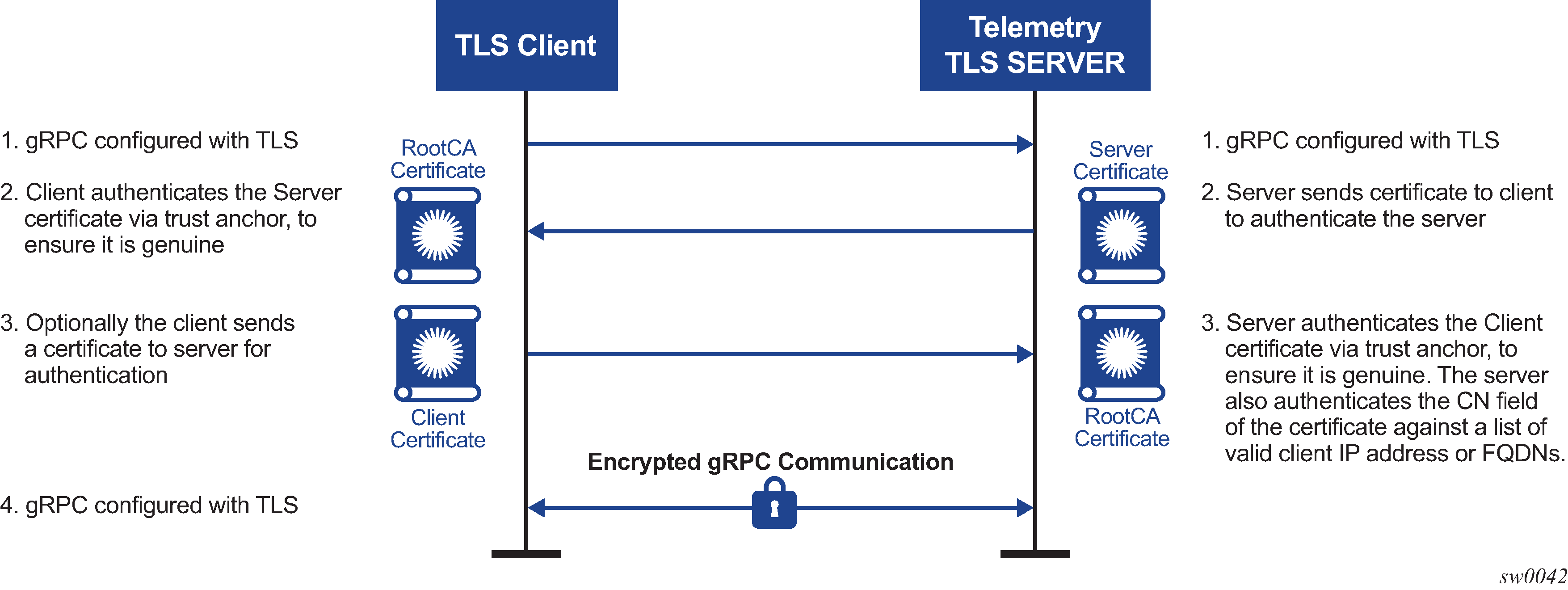
Channel credentials use username and password authentication. Each gRPC channel packet can contain a username and a password. Authentication is done through standard SR OS authentication order and mechanisms. All current authentication methods, including local and AAA servers, are applicable to gRPC channels. In addition, all authentication orders currently used by Telnet or SSH are compatible with gNMI Call authentication.
gNMI call authentication using SR OS shows a basic gNMI Call authentication using SR OS.
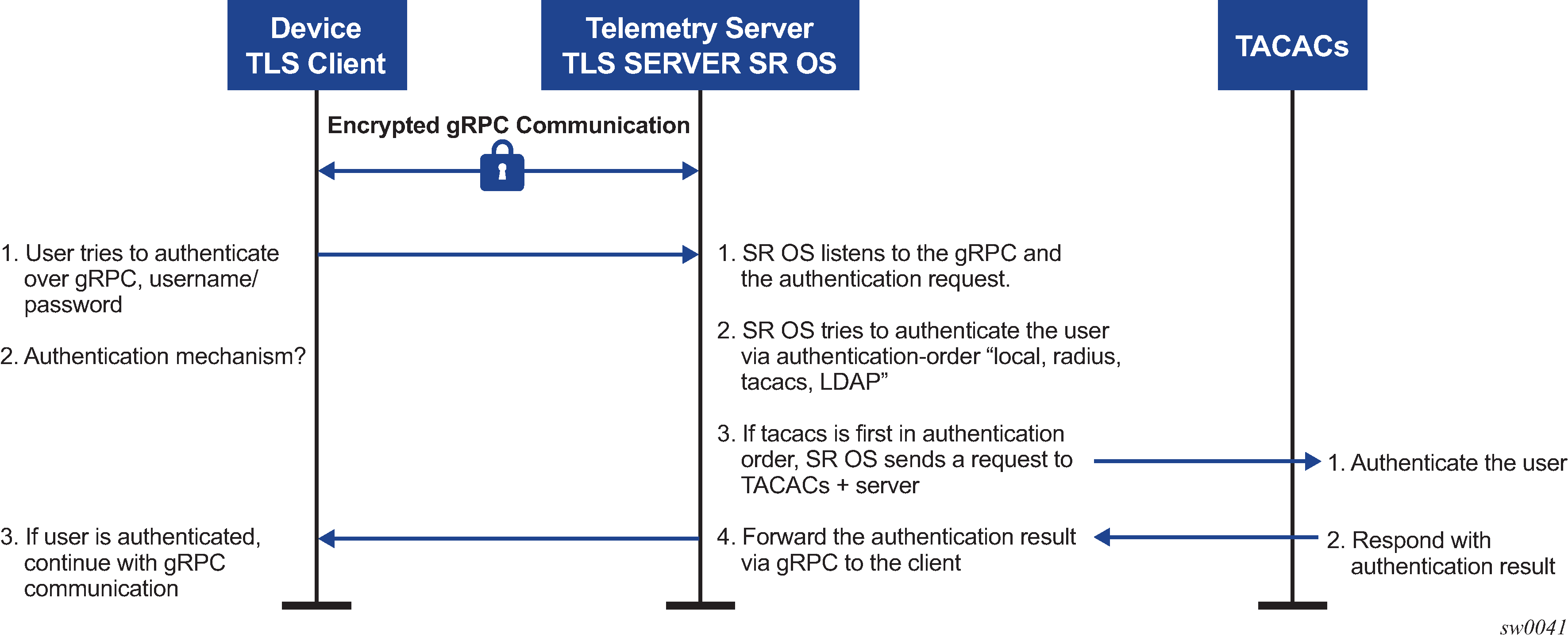
The gRPC channel packets contain the username and password in clear text, and are only encrypted using TLS. If a TLS server profile is assigned to the gRPC session, all PDUs between the server and client are encrypted. If TLS becomes operationally down, no gRPC PDUs are transmitted in clear text.
SR OS relies on existing authentication mechanisms for gRPC channels, including the following:
- Use the following command to configure AAA servers and local authentication order:
- MD-CLI
configure system security user-params authentication-order - classic
CLI
configure system security password authentication-order
- MD-CLI
password complexity rules
Use the following command to configure users as part of gRPC access:
- MD-CLI
configure system security user-params local-user user access grpc - classic
CLI
configure system security user access grpc
- MD-CLI
Use admin disconnect to disconnect the gRPC session for the session ID
Note: The gRPC is not affected by the password aging.
Security profiles can authorize bulk get, set, and subscribe gRPC commands that are received by the server. Profiles can be configured to allow or deny specific gRPC commands; for example, a profile for one user can authorize get and set commands, while a profile for another user can authorize get commands only.
Hash management per management interface configuration
Hash management is configurable per management interface for example, for the following:
- MD-CLI
- classic CLI
- NETCONF
- gRPC
Each management interface has its own write-hash algorithm. Depending on which management interface the user logs into, the write hash of that interface should be checked and used for displaying the critical phrases.
In the classic CLI interface, the read and write hash algorithms can be different, for example, hash for write and hash2 for read.
In the MD-CLI, NETCONF, and gRPC interfaces, when a hash is configured, only write is implemented using that hash algorithm. For example, if hash2 is configured, SR OS displays the phrase in hash2 format and reads the phrase in all formats. The read algorithm is not affected by hash algorithm configuration and SR OS reads in all hash formats.
Hash encryption using AES-256
Hash and hash2 use the AES-256 algorithm for all interfaces. However, hash2 uses module-specific text to make the hash unique per module or protocol. For example, BGP uses a different pre-pending text than IGP. This pre-pending text is appended to the key and then hashed using hash2.
In the classic CLI, hash has been changed to AES-256. Upgrade from DES to AES-256 is allowed and loading a config file in classic CLI with DES to a new software that supports AES-256 is also allowed.
The DES and the DES key should only be used for decryption of the old password to obtain clear text and the password should then be rehashed using AES-256. The few characters of the old hashed phrase are used to determine that the phrase is hashed using DES.
Cleartext
The cleartext option for the write algorithm displays the hash in clear text in the config file, info, info detail, and so on.
Configuring security with CLI
This section provides information to configure security using the command line interface.
Security configurations
This section provides configuration examples for the following security capabilities:
user profiles
user access parameters
password management parameters
authentication, authorization, and accounting using local, RADIUS, TACACS+, or LDAP
filtering using CPM filters and management access filters
Security configuration requirements list the capabilities of authentication, authorization, and accounting configurations. For example, authentication can be enabled locally and on RADIUS, TACACS+, and LDAP servers. Authorization can be executed locally, on a RADIUS server, or on a TACACS+ server. Accounting can be performed on a RADIUS or TACACS+ server.
| Authentication | Authorization | Accounting |
|---|---|---|
|
Local |
Local |
None |
|
RADIUS |
Local and RADIUS |
RADIUS |
|
TACACS+ |
Local |
TACACS+ |
|
LDAP |
None |
None |
Configuring management access filters
The following example shows a management access filter configuration that accepts packets matching the criteria specified in IP, IPv6, and MAC entries. Non-matching packets are denied.
MD-CLI
[ex:/configure system security management-access-filter]
A:admin@node-2# info
    ip-filter {
        default-action reject
        entry 10 {
            description "Accept SSH from mgmnt subnet"
            action accept
            match {
                protocol tcp
                src-ip {
                    address 192.168.5.0/26
                }
                dst-port {
                    port 22
                    mask 65535
                }
            }
        }
    }
    ipv6-filter {
        default-action accept
        entry 10 {
            action reject
            log-events true
            match {
                next-header rsvp
                src-ip {
                    address 2001:db8:1000::/64
                }
            }
        }
    }
    mac-filter {
        default-action accept
        entry 12 {
            action accept
            match {
                service "1"
                frame-type ethernet-ii
                src-mac {
                    address 00:01:01:01:01:01
                    mask ff:ff:ff:ff:ff:ff
                }
            }
        }
    }
classic CLI
A:node-2>config>system>security>mgmt-access-filter# info
----------------------------------------------
                ip-filter
                    default-action deny
                    entry 10
                        description "Accept SSH from mgmnt subnet"
                        src-ip 192.168.5.0/26
                        protocol tcp
                        dst-port 22 65535
                        action permit
                    exit
                exit
                ipv6-filter
                    default-action permit
                    entry 10
                        src-ip 2001:db8:1000::/64
                        next-header rsvp
                        log
                        action deny
                    exit
                exit
                mac-filter
                    default-action permit
                    entry 12
                        match frame-type ethernet_II
                            svc-id 1
                            src-mac 00:01:01:01:01:01 ff:ff:ff:ff:ff:ff
                        exit
                        action permit
                    exit
                exit
----------------------------------------------
Configuring IP CPM filters
Nokia recommends using a strict CPM filter policy allowing traffic from trusted IP subnets for protocols and ports actively used in the router and to explicitly drop other traffic.
The following configuration example uses these recommendations for SSH and BGP:
allow SSH from trusted subnet only
allow BGP from trusted subnet only
explicitly deny all other traffic and operationally log unexpected packets
MD-CLI
[ex:/configure system security cpm-filter]
A:admin@node-2# info
    default-action drop
    ip-filter {
        admin-state enable
        entry 100 {
            description "SSH: server terminated TCP sessions from trusted subnets"
            match {
                protocol tcp
                src-ip {
                    ip-prefix-list "trusted-mgmt-subnet"
                }
                dst-port {
                    eq 22
                    mask 65535
                }
            }
            action {
                accept
            }
        }
        entry 200 {
            description "BGP: server terminated TCP Sessions"
            match {
                protocol tcp
                src-ip {
                    ip-prefix-list "trusted-bgp-subnet"
                }
                dst-port {
                    eq 179
                    mask 65535
                }
            }
            action {
                accept
            }
        }
        entry 300 {
            description "BGP: client responses for initiated TCP sessions"
            match {
                protocol tcp
                src-ip {
                    ip-prefix-list "trusted-bgp-subnet"
                }
                src-port {
                    eq 179
                    mask 65535
                }
            }
            action {
                accept
            }
        }
        entry 6000 {
            description "Drop all other UDP"
            log 102
            match {
                protocol udp
            }
            action {
                drop
            }
        }
        entry 6010 {
            description "drop all other TCP"
            log 103
            match {
                protocol tcp
            }
            action {
                drop
            }
        }
    }
classic CLI
A:node-2>config>sys>security>cpm-filter# info
----------------------------------------------
              default-action drop
              ip-filter
                  entry 100 create
                      action accept
                      description "SSH: server terminated TCP sessions from trusted
subnets"
                      match protocol tcp
                          dst-port 22 65535
                          src-ip ip-prefix-list "trusted-mgmt-subnet"
                      exit
                  exit
                  entry 200 create
                      action accept
                      description "BGP: server terminated TCP Sessions"
                      match protocol tcp
                          dst-port 179 65535
                          src-ip ip-prefix-list "trusted-bgp-subnet"
                      exit
                  exit
                  entry 300 create
                      action accept
                      description "BGP: client responses for initiated TCP sessions"
                      match protocol tcp
                          src-ip ip-prefix-list "trusted-bgp-subnet"
                          src-port 179 65535
                      exit
                  exit
                  entry 6000 create
                      action drop
                      description "Drop all other UDP"
                      log 102
                      match protocol udp
                      exit
                  exit
                  entry 6010 create
                      action drop
                      description "drop all other TCP"
                      log 103
                      match protocol tcp
                      exit
                  exit
                  no shutdown
              exit
----------------------------------------------
Configuring IPv6 CPM filters
Nokia recommends using a strict CPM filter policy allowing traffic from trusted IP subnets for protocols and ports actively used in the router and to explicitly drop other traffic.
The following configuration example uses these recommendations for SSH and BGP:
allow SSH from trusted subnet only
allow BGP from trusted subnet only
explicitly deny all other traffic and operationally log unexpected packets
MD-CLI
[ex:/configure system security cpm-filter]
A:admin@node-2# info
    default-action drop
    ip-filter {
        admin-state enable
        entry 100 {
            description "SSH: server terminated TCP sessions from trusted subnets"
            match {
                protocol tcp
                src-ip {
                    ip-prefix-list "trusted-mgmt-subnet"
                }
                dst-port {
                    eq 22
                    mask 65535
                }
            }
            action {
                accept
            }
        }
        entry 200 {
            description "BGP: server terminated TCP Sessions"
            match {
                protocol tcp
                src-ip {
                    ip-prefix-list "trusted-bgp-subnet"
                }
                dst-port {
                    eq 179
                    mask 65535
                }
            }
            action {
                accept
            }
        }
        entry 300 {
            description "BGP: client responses for initiated TCP sessions"
            match {
                protocol tcp
                src-ip {
                    ip-prefix-list "trusted-bgp-subnet"
                }
                src-port {
                    eq 179
                    mask 65535
                }
            }
            action {
                accept
            }
        }
        entry 6000 {
            description "Drop all other UDP"
            log 102
            match {
                protocol udp
            }
            action {
                drop
            }
        }
        entry 6010 {
            description "drop all other TCP"
            log 103
            match {
                protocol tcp
            }
            action {
                drop
            }
        }
    }
    ipv6-filter {
        admin-state enable
        entry 100 {
            description "SSH: server terminated TCP sessions from trusted subnets"
            match {
                next-header tcp
                src-ip {
                    ipv6-prefix-list "trusted-mgmt-subnet"
                }
                dst-port {
                    eq 22
                    mask 65535
                }
            }
            action {
                accept
            }
        }
        entry 200 {
            description "BGP: server terminated TCP Sessions"
            match {
                next-header tcp
                src-ip {
                    ipv6-prefix-list "trusted-bgp-subnet"
                }
                dst-port {
                    eq 179
                    mask 65535
                }
            }
            action {
                accept
            }
        }
        entry 300 {
            description "BGP: client responses for initiated TCP sessions"
            match {
                next-header tcp
                src-ip {
                    ipv6-prefix-list "trusted-bgp-subnet"
                }
                src-port {
                    eq 179
                    mask 65535
                }
            }
            action {
                accept
            }
        }
        entry 6000 {
            description "Drop all other UDP"
            log 102
            match {
                next-header udp
            }
            action {
                drop
            }
        }
        entry 6010 {
            description "drop all other TCP"
            log 103
            match {
                next-header tcp
            }
            action {
                drop
            }
        }
    }
classic CLI
A:node-2>config>sys>security>cpm-filter# info
----------------------------------------------
              default-action drop
              ip-filter
                  entry 100 create
                      action accept
                      description "SSH: server terminated TCP sessions from trusted
subnets"
                      match protocol tcp
                          dst-port 22 65535
                          src-ip ip-prefix-list "trusted-mgmt-subnet"
                      exit
                  exit
                  entry 200 create
                      action accept
                      description "BGP: server terminated TCP Sessions"
                      match protocol tcp
                          dst-port 179 65535
                          src-ip ip-prefix-list "trusted-bgp-subnet"
                      exit
                  exit
                  entry 300 create
                      action accept
                      description "BGP: client responses for initiated TCP sessions"
                      match protocol tcp
                          src-ip ip-prefix-list "trusted-bgp-subnet"
                          src-port 179 65535
                      exit
                  exit
                  entry 6000 create
                      action drop
                      description "Drop all other UDP"
                      log 102
                      match protocol udp
                      exit
                  exit
                  entry 6010 create
                      action drop
                      description "drop all other TCP"
                      log 103
                      match protocol tcp
                      exit
                  exit
                  no shutdown
              exit
              ipv6-filter
                  entry 100 create
                      action accept
                      description "SSH: server terminated TCP sessions from trusted
subnets"
                      match next-header tcp
                          dst-port 22 65535
                          src-ip ipv6-prefix-list "trusted-mgmt-subnet"
                      exit
                  exit
                  entry 200 create
                      action accept
                      description "BGP: server terminated TCP Sessions"
                      match next-header tcp
                          dst-port 179 65535
                          src-ip ipv6-prefix-list "trusted-bgp-subnet"
                      exit
                  exit
                  entry 300 create
                      action accept
                      description "BGP: client responses for initiated TCP sessions"
                      match next-header tcp
                          src-ip ipv6-prefix-list "trusted-bgp-subnet"
                          src-port 179 65535
                      exit
                  exit
                  entry 6000 create
                      action drop
                      description "Drop all other UDP"
                      log 102
                      match next-header udp
                      exit
                  exit
                  entry 6010 create
                      action drop
                      description "drop all other TCP"
                      log 103
                      match next-header tcp
                      exit
                  exit
                  no shutdown
              exit
----------------------------------------------
Configuring MAC CPM filters
The following example shows a MAC CPM filter configuration.
MD-CLI
[ex:/configure system security cpm-filter mac-filter]
A:admin@node-2# info
    admin-state enable
    entry 10 {
        description "MAC-CPM-Filter 10.10.10.100 #007"
        match
        log 101
        action {
            drop
        }
    }
    entry 20 {
        description "MAC-CPM-Filter 10.10.10.100 #008"
        match
        log 101
        action {
            drop
        }
    }
classic CLI
A:node-2>config>sys>sec>cpm>mac-filter# info
----------------------------------------------
                    entry 10 create
                        description "MAC-CPM-Filter 10.10.10.100 #007"
                        match
                        exit
                        log 101
                        action drop
                    exit
                    entry 20 create
                        description "MAC-CPM-Filter 10.10.10.100 #008"
                        match
                        exit
                        log 101
                        action drop
                    exit
                    no shutdown
----------------------------------------------
Configuring CPM queues
CPM queues can be used for troubleshooting purposes to provide rate limit capabilities for traffic destined for CPM as described in an earlier section of this document.
The following example displays a CPM queue configuration.
MD-CLI
[ex:/configure system security cpm-queue]
A:admin@node-2# info
    queue 101 {
        rate {
            pir 100
        }
    }
classic CLI
config>sys>security>cpm-queue# info
----------------------------------------------
                queue 101 create
                    rate 100
                exit
----------------------------------------------
IPsec certificate configuration
The following example shows importation of a certificate from a PEM format.
Importing a certificate from PEM format (classic CLI)
A:node-2# admin certificate import type cert input cf3:/pre-import/R1-0cert.pem
                output R1-0cert.der format pem
The following example shows the exportation of a certificate to PEM format.
Exporting a certificate to PEM format (classic CLI)
A:node-2# admin certificate export type cert input R1-0cert.der output cf3:/
                R1-0cert.pem format pem
The following example shows certificate authority (CA) profile configuration.
CA profile configuration (MD-CLI)
[ex:/configure system security pki]
A:admin@node-2# info
    ca-profile "Root" {
        admin-state enable
        description "Root CA"
        cert-file "R1-0cert.der"
        crl-file "R1-0crl.der"
    }
CA profile configuration (class CLI)
A:node-2>config>system>security>pki# info
----------------------------------------------
                ca-profile "Root" create
                    description "Root CA"
                    cert-file "R1-0cert.der"
                    crl-file "R1-0crl.der"
                    no shutdown
                exit
----------------------------------------------
The following example shows IKE policy with cert-auth configuration.
IKE policy with cert-auth configuration (MD-CLI)
[ex:/configure ipsec ike-policy 1]
A:admin@node-2# info
    ike-version-2 {
        auth-method cert
        own-auth-method psk
    }
IKE policy with cert-auth configuration (classic CLI)
A:node-2>config>ipsec>ike-policy# info
----------------------------------------------
            ike-version 2
            auth-method cert-auth
            own-auth-method psk
----------------------------------------------
The following example shows a static LAN-to-LAN configuration using cert-auth.
Static LAN-to-LAN configuration using cert-auth (MD-CLI)
...
[ex:/configure service vprn "new"]
A:admin@node-2# info
    interface "VPRN1" {
        tunnel true
        sap tunnel-1.private:1 {
            ipsec-tunnel "Sanity-1" {
                admin-state enable
                key-exchange {
                    dynamic {
                        ike-policy 1
                        ipsec-transform [1]
                        pre-shared-key "qGAaHFZ9e/YXSsSCzlYbYWetW+Md2bDwwA==" hash2
                        cert {
                            cert-profile "M2cert.der"
                            trust-anchor-profile "R1-0"
                        }
                    }
                }
                tunnel-endpoint {
                    local-gateway-address 10.1.1.13
                    remote-ip-address 10.1.1.15
                    delivery-service "300"
                }
                security-policy {
                    id 1
                }
            }
        }
    }
Static LAN-to-LAN configuration using cert-auth (classic CLI)
...
A:node-2>config>service>vprn# info
    interface "VPRN1" tunnel create
        sap tunnel-1.private:1 create
            ipsec-tunnel "Sanity-1" create
                security-policy 1
                local-gateway-address 10.1.1.13 peer 10.1.1.15 delivery-service 300
                dynamic-keying
                    ike-policy 1
                    pre-shared-key "Sanity-1"
                    transform 1
                    cert
                        trust-anchor "R1-0"
                        cert "M2cert.der"
                        key "M2key.der"
                    exit
                exit
                no shutdown
            exit
        exit
    exit
Configuring local command authorization profiles
Profiles are used to deny or allow access to a hierarchical branch or specific commands.
The following example displays a local command authorization profile called ‟ghost” that is associated with a username ‟userA”.
MD-CLI
[ex:/configure system security aaa local-profiles]
A:admin@node-2# info
    profile "ghost" {
        default-action permit-all
        entry 1 {
            match "configure"
            action permit
        }
        entry 2 {
            match "configure service vprn <22>"
            action read-only
        }
        entry 3 {
            match "show"
        }
        entry 4 {
            match "exit"
        }
    }
[ex:/configure system security user-params local-user]
A:admin@node-2# info
user "userA" {
console {
member ["ghost"]
}
} classic CLI
A:node-2>config>system>security# info
----------------------------------------------
...
            profile "ghost"
                default-action permit-all
                entry 1
                    match "configure"
                    action permit
                exit
                entry 2
                    match "configure service vprn <22>"
                    action read-only
                exit
                entry 3
                    match "show"
                exit
                entry 4
                    match "exit"
                exit
            exit
...
----------------------------------------------
A:node-2>config>system>security# info
----------------------------------------------
...
user "userA"
...
console
member "ghost"
exit
... Matching on values in command authorization rules
In addition to matching on command keywords, command authorization profiles allow matching on the values of command elements.
Matching on a command element value (MD-CLI)
configure system security aaa local-profiles profile "service-ops" entry 10 match "configure service vprn <55>"Matching on a command element value (classic CLI)
configure system security profile "service-ops" entry 10 match "configure service vprn <55>"The following rules apply to matching on values:
-
Rule 1
- MD-CLI
For command authorization matching on commands that you enter in the MD-CLI, you can specify the match value with or without angle brackets (< >) around the command argument. If the match value is not in angle brackets, the match does not occur against that value when you enter the command in the classic CLI.
- classic CLI
For command authorization matching on commands that you enter in the classic CLI, you must specify the match value in angle brackets in the match command argument, as shown in the Matching on a command element value (classic CLI) example.
- MD-CLI
-
Rule 2
- MD-CLI
Only the value of key leafs can be matched in a command authorization rule.
- classic CLI
The value of any element can be matched in a command authorization rule.
- MD-CLI
-
Rule 3
When a value in angle brackets is present in a match command argument, all key values to the left of the value must also be specified (in angle brackets). See Using wildcards in command authorization value matching for more information.
-
Rule 4
You can either specifically state or completely omit a match value in the match string, as required. However, all unnamed parameters in the CLI command must be present in the match string when you use matching on a value. The following example shows how to match on OSPF to allow or deny access to all of OSPF.
match ‟configure router ospf” action denyAlternatively, use the following command to allow a specific OSPF instance for a user.
match ‟configure router ospf <0> <10.10.10.1>” action permit -
Rule 5
To generate the correct match behavior when multiple unnamed parameters are present in the match string, you must provide the parameters in the correct order as described in the command help. For example, in the second match example shown in Rule 4, the OSPF instance (0) must come before the router ID (10.10.10.1).
Match value configuration (MD-CLI)
[ex:/configure system security aaa local-profiles profile "default"]
A:admin@node-2# info
    entry 10 {
        match "show router <22> route-table"
        action permit
    }
    entry 20 {
        match "configure service vprn <22>"
        action read-only
    }
    entry 30 {
        match "show service id <22>"
        action permit
    }
    entry 40 {
        match "configure router interface <system>"
        action deny
    }
Match value configuration (classic CLI)
A:node-2>config>system>security>profile# info
                entry 10
                    match "show router <22> route-table "
                    action permit
                exit
                entry 20
                    match "configure service vprn <22>"
                    action read-only
                exit
                entry 30
                    match "show service id <22>"
                    action permit
                exit
                entry 40
                    match "configure router interface <system>"
                    action deny
                exit
Using wildcards in command authorization value matching
In addition to matching on specific values in command authorization profiles (see Matching on values in command authorization rules), wildcard matching is supported for matching against values in the following commands, when these commands are executed in the classic CLI engine:
- oam commands
- ping
- traceroute
- mtrace
For example, use the following command for wildcard matching on a value <.*>.
match "oam ancp subscriber <.*> loopback"Wildcard value matching is particularly useful when you want to match on a string that contains multiple values, but you only want a specific match on one of the values. The following example shows a command authorization profile with a list of all the permitted IP addresses for ping in router 10.
Using a list of all the permitted IP addresses as match values
match ping <10.0.0.1> router <10>
action permit
match ping <10.0.0.2> router <10>
action permit
Alternatively, you can use wildcard value matching, which allows a simpler match criterion. In the following example, the use of the <.*> wildcard enables the ability to ping any address in the router 10 context, that is, any address in VRF 10.
Using wildcards for IP address matching
match ping <.*> router <10>
action permitWildcard usage to avoid
match ping <.*> router <.*>
action permit
CLI session resource management
SR OS has the capability to manage Telnet/SSH sessions per user and at a higher level per system. At the system level, the user can configure a CLI-session group for different customer priorities. The cli-session-group command is a container that sets the maximum number of CLI sessions for a class of customers, with a unique session limit for each customer. For example, as shown in CLI session groups for customer classes, ‟Gold” category customers can have a CLI-session group that allows them more Telnet/SSH sessions compared to ‟Silver” category customers.
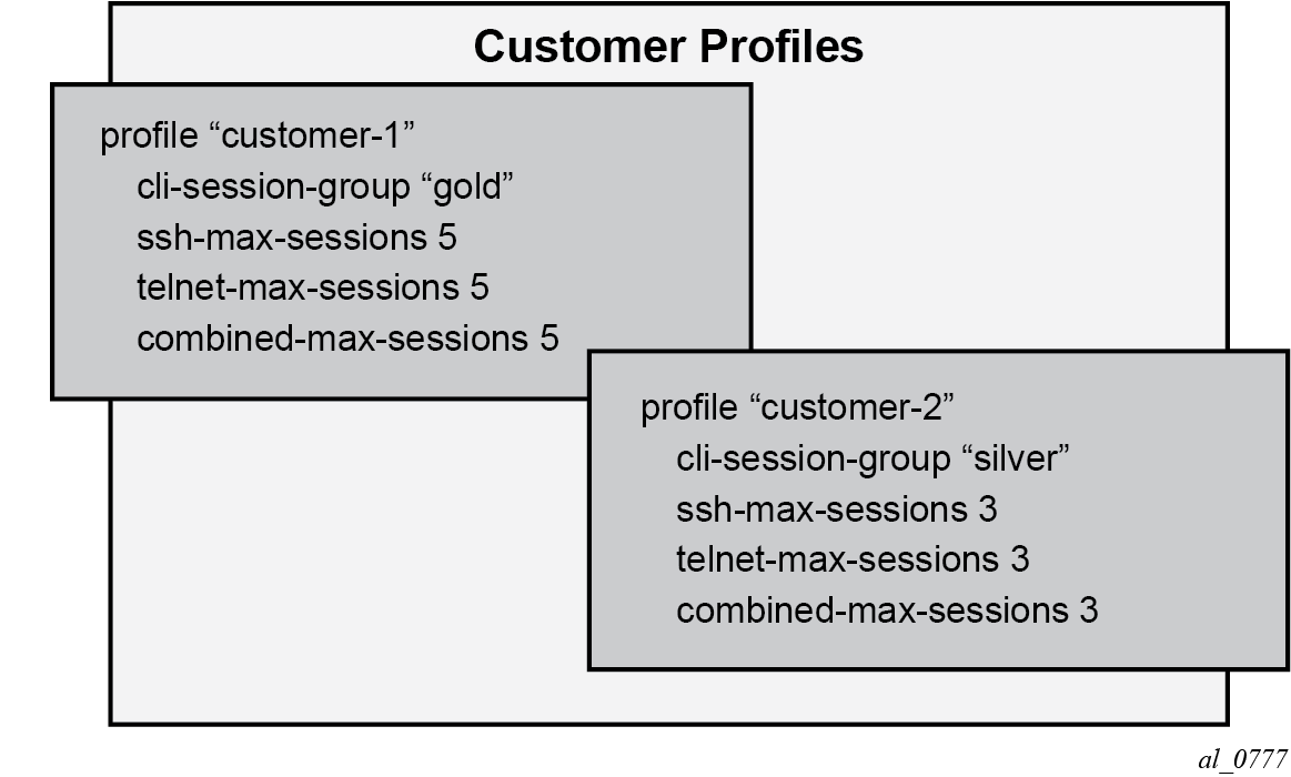
The configured cli-session-group can be assigned to user profiles. Each user profile can be configured with its own max SSH/Telnet session and is policed/restricted by the higher order cli-session-group that is assigned to it.
As shown in Hierarchy of CLI session group profiles, the final picture is a hierarchical configuration with top-level cli-session-groups that control each customer’s total number of SSH or Telnet sessions and the user-profile for each user for that customer.
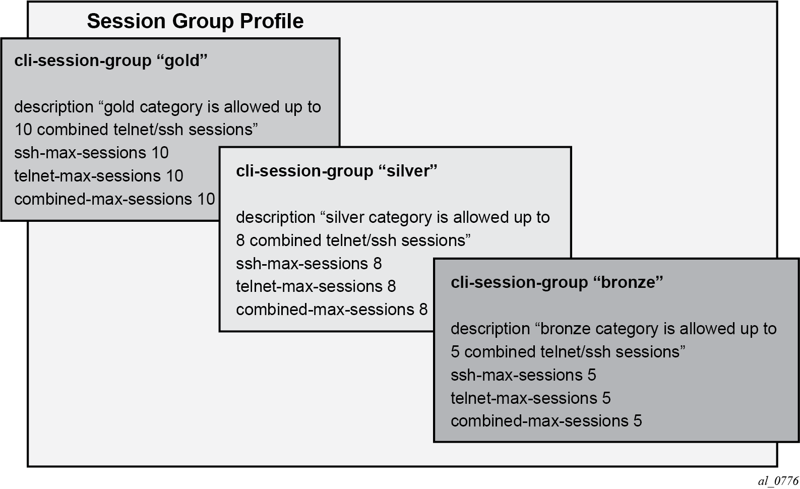
Every profile subtracts one from its corresponding maximum session when a Telnet or SSH session is established in the following cases:
where multiple profiles are configured under a user
where multiple profiles arrive from different AAA servers (Local Profile, RADIUS Profile or TACACS Profile)
The first profile to run out of corresponding max-session limits future Telnet or SSH sessions. In other words, while each profile for the user can have its independent max-session, only the lowest one is honored. If the profile with the lowest max-session is removed, the next lower profile max-session is honored and so on. All profiles for a user are updated when a Telnet or SSH session is established.
For information about login control, see Configuring login controls.
Use the commands ssh-max-sessions, telnet-max-sessions, combined-max-sessions, and cli-session-group in the following context to configure CLI session resources:
- MD-CLI
configure system security aaa local-profiles profile - classic
CLI
configure system security profile
Configuring users
Configure access for individual users. Include the user's login name and optionally include information that identifies the user.
MD-CLI
[ex:/configure system security user-params local-user]
A:admin@node-2# info
    user "userA" {
        password "$2y$10$pFoehOg/tCbBMPDJ/kqpu.8af0AoVGY2xsR7WFqyn5fVTnwRzGmOK"
        restricted-to-home true
        access {
            console true
            ftp true
            snmp true
        }
        console {
            member ["default" "ghost"]
        }
    }
classic CLI
A:node-2>config>system>security# info
----------------------------------------------
...
            user "userA"
                password "$2y$10$pFoehOg/tCbBMPDJ/
kqpu.8af0AoVGY2xsR7WFqyn5fVTnwRzGmOK"
                access console ftp snmp
                restricted-to-home
                console
                    member "default"
                    member "ghost"
                exit
            exit
...
--------------------------------------------
Configuring keychains
The following example shows a keychain configuration.
MD-CLI
[ex:/configure system security keychains]
A:admin@node-2# info
    keychain "abc" {
        bidirectional {
            entry 1 {
                authentication-key "LHDhK3oGRvkiefQnx7OOc/yutg==" hash2
                algorithm aes-128-cmac-96
                begin-time 2006-12-18T22:55:20.0+00:00
            }
        }
    }
    keychain "basasd" {
        receive {
            entry 1 {
                authentication-key "LHDhK3oGRvkiefQnx7OOc3ib6A==" hash2
                algorithm aes-128-cmac-96
                tolerance infinite
            }
        }
    }
classic CLI
A:node-2>config>system>security# info
----------------------------------------------
...
            keychain "abc"
                direction
                    bi
                        entry 1 key "ZcvSElJzJx/wBZ9biCtOVQJ9YZQvVU.S" hash2 alg
orithm aes-128-cmac-96
                            begin-time 2006/12/18 22:55:20
                        exit
                    exit
                exit
            exit
            keychain "basasd"
                direction
                    uni
                        receive
                            entry 1 key "Ee7xdKlYO2DOm7v3IJv/84LIu96R2fZh" hash2
 algorithm aes-128-cmac-96
                                tolerance forever
                            exit
                        exit
                    exit
                exit
            exit
...
----------------------------------------------
Copying and overwriting users and profiles
You can copy a user or a user profile.
User
Use the following command to copy a user configuration to another user configuration.
- MD-CLINote: In the MD-CLI, the copy command is a global command.
configure system security user-params local-user copy user username to user username - classic CLINote: If the destination profile or user already exists, you must specify the overwrite option to avoid an error.
configure system security copy user username to user username overwrite
The cannot-change-password option is not replicated when you perform a copy user command. The following example shows the new-password-at-login option is created instead.
MD-CLI
[ex:/configure system security user-params local-user]
A:admin@node-2# info
...
    }
    user "user1" {
        password "$2y$10$YlCd8TWpvgpFpm92lf2ZY.gb4lejb96GZocMJ0/JhwUnhP7BQZ06e"
        access {
            snmp true
        }
        console {
            cannot-change-password true
            member ["default"]
        }
        snmp {
            group "testgroup"
        }
    }
    user "user2" {
        password "$2y$10$m.xtXmULRSHf4svGAj.p..wlXHMhWj/fF1jsF0p0beSOSmx8J9Vfa"
        access {
            snmp true
        }
        console {
            new-password-at-login true
            member ["default"]
        }
        snmp {
            group "testgroup"
        }
    }
...
classic CLI
A:node-2>config>system>security>user# info
----------------------------------------------
user "userA"
password "$2y$10$pFoehOg/tCbBMPDJ/kqpu.8af0AoVGY2xsR7WFqyn5fVTnwRzGmOK"
     access snmp
     console
          cannot-change-password
     exit
     snmp
         group "testgroup"
     exit
exit
----------------------------------------------
A:node-2>config>system>security>user# info
----------------------------------------------
user "userB" password ""
     access snmp
     console
          new-password-at-login
     exit
     snmp
          group "testgroup"
     exit
exit
---------------------------------------------
Profile
Use the copy and to commands to copy a profile configuration to another profile configuration.
- MD-CLINote: In the MD-CLI, the copy command is a global command.
configure system security aaa local-profiles copy profile user-profile-name to profile user-profile-name - classic
CLI
configure system security copy profile source-profile-name to destination-profile-name
RADIUS configurations
Configuring RADIUS authentication
RADIUS is disabled by default and must be explicitly enabled. The RADIUS server commands add the RADIUS server. The mandatory configurations to enable the RADIUS server on the local router include the server index, IP address, and secret key. The index determines the sequence in which the servers are queried for authentication requests. In addition, configure the port, and retry and timeout intervals. The other configuration aspects are optional.
The system IP address must also be configured for the RADIUS client to work. For more information, see the 7450 ESS, 7750 SR, 7950 XRS, and VSR Router Configuration Guide, "Configuring a System Interface".
Use the commands in the following context to enable the RADIUS server on the local router:
- MD-CLI
configure system security aaa remote-servers radius - classic
CLI
configure system security radius
MD-CLI
[ex:/configure system security aaa remote-servers radius]
A:admin@node-2# info
    server-retry 5
    server-timeout 5
    server 1 {
        address 10.10.10.103
        secret "G08OmFGXGZjnMgeFRMlrNp8Odc0s" hash2
    }
    server 2 {
        address 10.10.0.1
        secret "YDA64iuZiGG847KPM+7Bvuj3waIn" hash2
    }
    server 3 {
        address 10.10.0.2
        secret "/WGgOvT3fYcPwh4F5+gGeOVvlfw1" hash2
    }
    server 4 {
        address 10.10.0.3
        secret "pOYk1obgPtJ2fAq9hcFEJp5tlxKa" hash2
    }
classic CLI
A:node-2>config>system>security# info
----------------------------------------------
             retry 5
             timeout 5
             server 1 address 10.10.10.103 secret "test1"
             server 2 address 10.10.0.1 secret "test2"
             server 3 address 10.10.0.2 secret "test3"
             server 4 address 10.10.0.3 secret "test4"
...
----------------------------------------
Configuring RADIUS authorization
For RADIUS authorization to function, you must first enable RADIUS authentication. See Configuring RADIUS authentication.
In addition to the local configuration requirements, configure VSAs on the RADIUS server. See Vendor-specific attributes.
Use the following command to configure RADIUS authorization on the local router:
- MD-CLI
configure system security aaa remote-servers radius authorization - classic
CLI
configure system security radius authorization
Configuring RADIUS accounting
Use the following CLI command to configure RADIUS accounting on the local router:
- MD-CLI
configure system security aaa remote-servers radius accounting - classic
CLI
configure system security radius accounting
Configuring 802.1x RADIUS policies
Use the commands in the following context to configure generic authentication for clients using 802.1x EAPOL. Additional options are configured per Ethernet port. For more information, see the 7450 ESS, 7750 SR, 7950 XRS, and VSR Interface Configuration Guide.
- MD-CLI
configure system security dot1x radius-policy - classic
CLI
configure system security dot1x radius-plcy
The following example shows an 802.1x configuration.
MD-CLI
[ex:/configure system security dot1x radius-policy "dot1x_plcy"]
A:admin@node-2# info
    admin-state enable
    source-address 10.1.1.255
    server 1 {
        address 10.1.1.1
        secret "ypeBEsobvcr6wjGzmiPcTfM=" hash2
        authentication-port 65535
    }
    server 2 {
        address 10.1.1.2
        secret "ypeBEsobvcr6wjGzmiPcTXk=" hash2
        authentication-port 65535
    }
classic CLI
A:node-2>config>system>security# info
----------------------------------------------
            dot1x
                radius-plcy "dot1x_plcy" create
                   server 1 address 10.1.1.1 port 65535 secret "a"
                   server 2 address 10.1.1.2 port 65535 secret "a"
                   source-address 10.1.1.255
                no shutdown
...
----------------------------------------------
TACACS+ configurations
Enabling TACACS+ servers with authentication
You can use TACACS+ authentication on the router. Use the commands in the following context to configure one or more TACACS+ servers on the network:
- MD-CLI
configure system security aaa remote-servers tacplus server - classic
CLI
configure system security tacplus server
The following example shows a TACACS+ configuration with authentication.
MD-CLI
[ex:/configure system security aaa remote-servers tacplus]
A:admin@node-2# info
    server-timeout 5
    server 1 {
        address 10.10.0.5
        secret "G08OmFGXGZjnMgeFRMlrNn1Ak0Vj" hash2
    }
    server 2 {
        address 10.10.0.6
        secret "YDA64iuZiGG847KPM+7BvsC4f/EL" hash2
    }
    server 3 {
        address 10.10.0.7
        secret "/WGgOvT3fYcPwh4F5+gGeBToxeh5" hash2
    }
    server 4 {
        address 10.10.0.8
        secret "pOYk1obgPtJ2fAq9hcFEJtCZ/Qj/" hash2
    }
    server 5 {
        address 10.10.0.9
        secret "oUDAwe2i3vK4MDY7o2KqTdr3cfHp" hash2
    }
classic CLI
A:node-2>config>system>security>tacplus# info
----------------------------------------------
          timeout 5
          server 1 address 10.10.0.5 secret "test1"
          server 2 address 10.10.0.6 secret "test2"
          server 3 address 10.10.0.7 secret "test3"
          server 4 address 10.10.0.8 secret "test4"
          server 5 address 10.10.0.9 secret "test5"
----------------------------------------------
Configuring TACACS+ authorization
For TACACS+ authorization to function, you must first enable TACACS+ authentication. See Enabling TACACS+ servers with authentication.
Use the command in the following context to configure TACACS+ authorization on the local router:
- MD-CLI
configure system security aaa remote-servers tacplus authorization - classic
CLI
configure system security tacplus authorization
Configuring TACACS+ accounting
Use the following command to configure TACACS+ accounting on the local router:
- MD-CLI
configure system security aaa remote-servers tacplus accounting - classic
CLI
configure system security tacplus accounting
LDAP configurations
Configuring LDAP authentication
LDAP is disabled by default and must be explicitly enabled. To use LDAP authentication on the router:
- Configure one or more LDAP servers on the network.
- Ensure that TLS certificates and clients are also configured; see TLS for information about TLS configuration in the SR OS.
Use the commands in the following context to configure LDAP:
- MD-CLI
configure system security aaa remote-servers ldap - classic
CLI
configure system security ldap
The following example shows the LDAP authentication configuration. See LDAP authentication for more information about the use of LDAP authentication in the SR OS.
MD-CLI
[ex:/configure system security aaa remote-servers ldap]
A:admin@node-2# info
    admin-state enable
    public-key-authentication true
    server 1 {
        admin-state enable
        server-name "active-server"
        tls-profile "server-1-profile"
        address 10.1.1.1 {
        }
        bind-authentication {
            root-dn "cn=administrator,cn=users,dc=nacblr2,dc=example,dc=com password"
        }
        search {
            base-dn "dc=sns,dc=example,dc=com"
        }
    }
[ex:/configure system security tls]
A:admin@node-2# info
    client-tls-profile "server-1-profile" {
        admin-state enable
        cipher-list "to-active-server"
        trust-anchor-profile "server-1-ca"
    }
classic CLI
A:node-2>config>system>security>ldap# info
----------------------------------------------
    public-key-authentication
    server 1 create
        address 10.1.1.1
        bind-authentication "cn=administrator,cn=users,dc=nacblr2,dc=example,dc=com
          password"
        ldap-server "active-server"
        search "dc=sns,dc=example,dc=com"
        tls-profile "server-1-profile"
        no shutdown
    exit
    no shutdown
----------------------------------------------
A:node-2>config>system>security>tls# info
----------------------------------------------
    client-tls-profile "server-1-profile" create
        cipher-list "to-active-server"
        trust-anchor-profile ‟server-1-ca‟
    no shutdown
    exit
Configuring redundant servers
You can configure up to five redundant LDAP servers. The following examples show configuration of two servers. Server 1 is active and server 5 is backup.
Active server configuration (MD-CLI)
[ex:/configure system security aaa remote-servers ldap]
A:admin@node-2# info
    public-key-authentication true
    server 1 {
        server-name "active-server"
        tls-profile "server-1-profile"
        address 10.1.1.1 {
        }
    }
[ex:/configure system security tls]
A:admin@node-2# info
    client-tls-profile "server-1-profile" {
        admin-state enable
        cert-profile "client-cert-profile"
        cipher-list "to-active-server"
        trust-anchor-profile "server-1-ca"
    }
Backup server configuration (MD-CLI)
[ex:/configure system security aaa remote-servers ldap]
A:admin@node-2# info
    public-key-authentication true
    server 5 {
        server-name "backup-server-5"
        tls-profile "server-5-profile"
        address 10.5.5.1 {
        }
[ex:/configure system security tls]
A:admin@node-2# info
    client-tls-profile "server-5-profile" {
        admin-state enable
        cert-profile "client-cert-profile"
        cipher-list "to-backup-server 5"
        trust-anchor-profile "server-5-ca"
        }
   }
Active server configuration (classic CLI)
A:node-2>config>system>security>ldap# info
    public-key-authentication
    server 1 create
        address 10.1.1.1
        ldap-server ‟active-server”
        tls-profile ‟server-1-profile”

A:node-2>config>system>security>tls# info
    client-tls-profile ‟server-1-profile” create
        cert-profile ‟client-cert-profile”
        cipher-list ‟to-active-server”
        trust-anchor-profile ‟server-1-ca”
        no shutdown
    exit
Backup server configuration (classic CLI)
A:node-2>config>system>security>ldap# info
    public-key-authentication
    server 5 create
        address 10.5.5.1
        ldap-server ‟backup-server-5”
        tls-profile ‟server-5-profile”

A:node-2>config>system>security>tls# info
    client-tls-profile ‟server-5-profile” create
        cert-profile ‟client-cert-profile”
        cipher-list ‟to-backup-server-5”
        trust-anchor-profile ‟server-5-ca”
        no shutdown
    exit
Configuring login controls
Configure login control for console, Telnet, and FTP sessions. The following example shows a login control configuration.
MD-CLI
[ex:/configure system]
A:admin@node-2# info
    login-control {
        exponential-backoff false
        idle-timeout 1440
        motd {
            text "Notice to all users: Software upgrade scheduled 3/2 1:00 AM"
        }
        pre-login-message {
            message "Property of Service Routing Inc. Unauthorized access prohibited."
        }
        ftp {
            inbound-max-sessions 5
        }
        telnet {
            inbound-max-sessions 7
            outbound-max-sessions 2
        }
    }
classic CLI
A:node-2>config>system# info
----------------------------------------------
...
       login-control
           ftp
               inbound-max-sessions 5
           exit
           telnet
               inbound-max-sessions 7
               outbound-max-sessions 2
           exit
           idle-timeout 1440
           pre-login-message "Property of Service Routing Inc. Unauthorized access
                              prohibited."
           motd text "Notice to all users: Software upgrade scheduled 3/2 1:00 AM"
       exit
 no exponential-backoff
...
----------------------------------------------