Peering configuration process
The following table lists the SR OS peering configuration tasks. Information in this guide is presented in an overall logical configuration flow. Each section describes a software area and provides the MD-CLI command usage to configure commands for the functional area.
| Area | Task | Section |
|---|---|---|
|
Peering configuration introduction |
Introduction to peering |
|
|
Peering topology |
||
|
Hardware configuration |
Configure line cards |
|
|
Configure ports and interfaces |
||
|
Routing protocols configuration |
Configure an IGP |
|
|
Configure BGP |
||
|
Peering configuration |
Configure route policies |
|
|
Configure cflowd |
||
| Configure RPKI for prefix origin validation | ||
| Configure FlowSpec | ||
| Configure uRPF | ||
|
System and routing security configuration |
Configure CPM filters |
|
|
Configure management access filter |
||
|
Configure ACLs |
||
|
Configure rate limiting for DDoS traffic |
||
|
Configure redirecting suspicious traffic |
||
|
Run ACL show commands |
||
|
QoS configuration |
Configure classification |
|
|
Configure queuing |
||
|
Configure scheduling |
||
|
Configure re-marking |
||
|
Additional system configuration (optional) |
Switching from the classic to the MD‑CLI |
|
|
User and profile management |
||
|
Configure NTP |
||
|
Configure system alarms and logging |
||
| Appendix A |
Configure custom CLI commands (pySROS) |
|
| Appendix B |
Configure configuration groups |
Introduction
Peering is an agreement established between two networks or two Autonomous Systems (ASs) to exchange routing information using the BGP protocol as described in this guide.
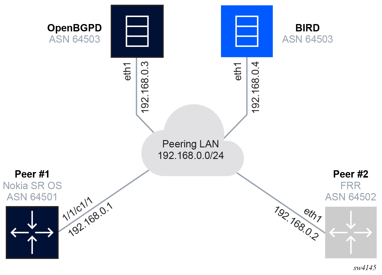
Topology
The configuration examples in this guide display the connection of the Peer #1 Nokia SR OS ASN 64501 router (shown in the following figure) as a peering router to the rest of the network.